Embed Size (px)
Citation preview
http://history.nasa.gov/rogersrep/v3appoe4.htmhttp://www.lostspacecraft.com/Images.html
Report of the PRESIDENTIAL COMMISSION on the Space Shuttle Challenger Accident
Volume 3: Appendix O - NASA Search, Recovery and Reconstruction Task Force TeamReport
Volume 2: Enclosure 4: SEARCH, CLASSIFICATION AND RECOVERY.
[O204] PREPARED BY:
Capt. Charles A. BartholomewUnited States NavySuperior of SalvageNaval Sea Systems CommandWashington, D.C.
[O205] NUMERICAL TABLE OF CONTENTS
I. INTRODUCTION. II. CONCEPT OF OPERATIONS FOR UNDERWATER SEARCH AND SALVAGE.
A. Planning.
1. Defined Search Area.2. Collected and Correlated Sonar Contact Information.3. Classified Sonar Contacts.4. Defined Contacts to be Recovered and Assigned Assets.
B. Concepts of STS 51-L Salvage Operations Plan.
1. Sonar Search.2. Contact Database.3. Sonar Contact Analysis.4. Classification of Contacts.5. Recovery Priorities.6. Employment of Recovery Assets.
C. Flow of Data and Record Keeping.D. Assets.
1. Ashore.2. Ships.3. ROV's Provided by SUPSALV.4. Manned Submersibles Provided by SUPSALV.5. Sonar Systems Provided by SUPSALV.6. Navigation Systems.
E. Selection and Employment of Assets for Salvage Operations.
1. Introduction.2. Vessels.3. Submersible Vehicles.
III. SEARCH RESULTS.
A. Initial Search Area.B. Expanded Search Area.C. Search Area Contact Summary and Location of Major STS 51-L Sections.D. Remarks on Search Operations.
1. Accuracy of Sonar Located Contacts.2. Side Scanning Sonar Remarks.
IV. CONTACT CLASSIFICATION RESULTS.
A. Introduction.B. NASA Priority Assignments for Recovery.C. Summary of Classification Efforts.D. Remarks on Classification Operations.
1. Bottom Topography.2. Discarded Equipment.3. Aerospace Debris.4. Miscellaneous Contacts.5. General Comments.
V. RECOVERY RESULTS.
A. Introduction.B. Summary of STS-51 Underwater Recovery Operations.C. Remarks on Recovery Operations.
1. Divers.2. Remotely Operated Vehicles (ROV's).3. Manned Submersibles.

4. NR-1.5. Effects of Environment.6. Random Scatter of Components.7. Position Accuracy of Recovered Components.
VI. CLOSING REMARKS. LIST OF FIGURES
1. STS 51-L Salvage Operations Organization.2. Initial Search Area3. Expanded Search Area4. Search Area Display of Contacts Identified During STS 51-L Search Operations5. Search Area Display of Contacts Classified STS 51-L6. Search Area Display of Salvaged STS 51-L Debris7. Right Hand SRB Located Debris8. Right Hand SRB Locations LIST OF TABLES 1. Search and Salvage Vessel Assets and Capabilities2. Summary of Contacts Classified STS 51-L Debris3. Salvage Plans for STS 51-L Components4. Summary of Underwater STS 51-L Contacts Recovered
STS 51-L SALVAGE OPERATION SEARCH, CLASSIFICATION, AND RECOVERY
[O206] I.INTRODUCTION
The U.S. Navy Supervisor of Salvage (SUPSALV) has been involved with the salvage ofobjects which require location, identification, and recovery from the ocean floor over thehistory of U.S. Navy salvage. Numerous aircraft, ships, and weapons systems componentshave required recovery for humanitarian, accident investigation, and security reasons.
Over the history of the Space Shuttle Program, the National Aeronautics and SpaceAdministration (NASA) and SUPSALV have worked together, specifically in the areas ofSolid Rocket Booster (SRB) recovery procedures and the identification of ships for SRBrecovery operations. During the recent years of the NASA Space Shuttle Program, NASA andSUPSALV personnel have established a solid working relationship and negotiated formalMemoranda of Agreement definitizing this relationship.
Because of SUPSALV's experiences in salvage operations, ability to deploy both military andcommercial assets for this effort, and developed working relationships with NASA, theSupervisor of Salvage was selected to head the Space Transportation System (STS) Mission51-L (hereafter referred to as STS 51-L) Salvage Operation. Therefore, On January 31, 1986,at NASA's request, the Department of Defense Manager for Space Transportation SystemContingency Support Operations (DDMS) requested U.S. Navy assistance from the Chief ofNaval Operations (CNO). CNO, in turn, tasked SUPSALV's parent command (Commander,Naval Sea Systems Command) to undertake the STS 51-L salvage, mission and requested thatCommander-in-Chief, U.S. Atlantic Fleet, provide support as necessary.
The following sections detail the salvage concepts employed, assets utilized, problemsencountered, and results obtained during the course of the salvage operation. The primarymission of the STS 51-L Salvage Operation, to recover critical pieces for determination ofmishap cause, has been achieved. Deep water salvage operations were terminated on May I,1986 and supporting assets demobilized. Ongoing salvage operations involving the recoveryof high-interest debris in shallow water areas are not related to the mishap cause. This reportdocuments events through May 1, 1986.
II. CONCEPTS OF OPERATIONS FOR UNDER WATER SEARCH AND SALVAGE
The planning for use and employment of assets for an underwater salvage operation of thiscomplexity and magnitude are dependent upon a continually changing set of contact data,priorities, and environmental conditions. Collected data, priority establishment, andenvironmental conditions are the primary planning inputs which determine when and howavailable assets can be most effectively utilized. The STS 51-L Mishap underwater salvageeffort consisted of three major overlapping phases: search, contact classification, andrecovery. These phases were conducted concurrently due to the enormous scope of the totalsearch operation and the time-critical requirement to recover key portions of the STS 51-Lflight hardware for determination of accident cause. Contact information obtained duringclassification and recovery phases markedly altered search area and contactclassification/recovery priorities. This section addresses the concept of operations forconducting the mission search, contact classification, and recovery phases of the salvageoperation. Execution details for each phase are addressed in Sections III, IV, and V,respectively, of this report.
A. Planning
This paragraph provides an overview of the planning inputs and concepts involved with thesearch and salvage operations.
1. Defined Search Area.
(a) Initially based on available data obtained from:
(1) Eastern Space and Missile Center (ESMC) tracking radars. (2) ESMC optical tracks. (3) Federal Aviation Administration (FAA) radar

(4) Visual sightings reported by aircraft in area during STS 51-L launch and immediatelyafter launch mishap. (5) Location of floating STS 51-L debris.
(b) Subsequently revised based on collected data from:
(1) Side scanning sonar contacts. (2) Identified STS 51-L debris (3) Additional radar and optical tracking data.
2. Collected and Correlated Sonar Contact Information.
(a) Contact number. (b) Date contact found. (c) Contact location (Latitude and Longitude). (d) Contact size. (e) Contact bottom orientation (debris field). (f) Contact water depth. (g) Contact correlation with other available data and information. (h) Contact description.
3. Classified Sonar Contacts.
(a) Contacts, evaluated as probable STS 51-L debris, prioritized by sonar contactstrength and geographic location factors to determine order of subsequent investigation. (b) Contact classification after visual verification (e. g., divers, photographs, or video).
4. Defined Contacts to be Recovered and Assigned Assets.
(a) Contact classification as Orbiter, Payload, External Tank, or SRB. (b) Salvage assets assigned by Supervisor of Salvage (SUPSALV) per NASA priorities.
B. Concepts of STS 51-L Salvage Operations Plan
1. Sonar Search
Conducted wide area search using side scanning sonar to locate contacts within the definedsearch areas. Sonar scan width was 300 meters wide (150 meters per side) with 135-metersearch line spacing to provide effective bottom area coverage with 1 65-meter (122 percent)overlapping of sonar coverage. Due to strong northern Gulf Stream currents existent in theeastern portions of the search area, ships conducted search lines in a southerly direction only.Although this involved additional repositioning time for conducting subsequent passes, it wasnecessary to ensure stability of the towed sonar "fish" in the strong currents and to achieve aconsistent "fish" speed over the bottom in the 2- to 4-knot range. As current conditionspermitted (i.e., less than 2.0 knots), search lines were conducted in both north and southdirections.
2. Contact Database
Compiled a data base of contacts identified within the search area using an HP-9000computer located on shore at the Supervisor of Salvage Command Post.
3. Sonar Contact Analysis
Analyzed sonar data based on characteristics of the sonar trace and location relative toknown or suspected STS 51-L pieces. A graded list of contacts to be verified was developedfrom this data.
4. Classification of Contacts
In order of NASA-assigned priorities, conducted positive identification and classificationof sonar contacts using the most effective available assets (i.e., divers, Remotely OperatedVehicles (ROV's), Manned Submersibles).
5. Recovery Priorities
Contacts prioritized by NASA were as follows:
(a) Right Solid Rocket Booster (SRB). (b) Orbiter, Crew Compartment. (c) Payload: Tracking and Data Relay Satellite System (TDRSS), and Inertial UpperStage (IUS). (d) Left SRB. (e) Specified Orbiter Components. (f) External Tank (ET).
[O207] 6. Employment of Recovery Assets
SUPSALV assigned assets to conduct recovery of contacts in accordance with overallNASA priorities.
C. Flow of Data and Record Keeping
1. Recorded data (e.g, video, sonar traces, photographs) obtained by salvage operationvessels were transferred to the Supervisor of Salvage Command Post via support craftdesignated for the purpose.
2. Daily situation reports (SITREPS) were transmitted to SUPSALV via radio by allvessels at 0800, 1200, and 1600 hours, local time.
3. The following records and reports were maintained by the Supervisor of Salvage:
(a) Daily SITREPS. (b) Master Event Log for STS 51-L Operations. (c) Sonar traces. (d) STS 51-L Salvage Operations Search and Contact Plot. (e) Sonar Contact Summary Evaluation Reports. (f) Search Line and Contact Summary Reports.
(g) Search Line Log (cumulative). (h) Field Notes on STS 51-L Salvage Operations. (i) Video tapes of contacts. (j) Still photographs of contacts. (k) Voice Radio Transmissions Log.
D. Assets
1. Ashore (Supervisor of Salvage Command Post):
(a) Supervisor of Salvage staff personnel. (b) Three vans for command, administrative, and technical evaluation personnel. (c) One HP-9000 Model 520 computer and two HP-7580A Plotters for tracking/plottingsearch area contacts and overall data management. (d) Ship-to-shore communications (UHF/VHF/telephone to MARISAT-capable ships). (e) Video system for reviewing and copying video film. (f) Technical personnel for evaluation of sonar data and maintenance of sonar data recordsand video.
2. Ships: (for more detailed information, see Table 1, Search and Salvage Vessel Assetsand Capabilities):
(a) NASA
(1) *M/V Liberty Star (2) M/V Independence (3) M/V Freedom Star
(b) U.S. Air Force (ESMC)
(1) LCU (USAF Range Salvage Vessel, C115-1925)
(c) U.S. Navy
(1) USS Preserve (ARS 8) (2) USS Opportune (ARS 41) (3) USS Sunbird (ASR 15) (4) NR-1 (5) USS Kittiwake (ASR 13)
(d) SUPSALV
(1) M/V Stena Workhorse (Tracor) (2) *R/V Seward Johnson (Eastport/Harbor Branch Foundation) (3) R/V Edwin Link (Eastport/Habor Branch Foundation) (4) M/V G.W. Pierce II (Tracor) (5) M/V Paul Langevin III (Tracor) (6) M/V Eliminator (Tracor/Canaveral Marina)
(7) M/V Pelican Princess (Tracor/Canaveral Marina)
3. ROV's Provided by SUPSALV (for more detailed information see Table 1, refer to shipnoted):
(a) Navy Deep Drone (M/V Independence) (b) Gemini (M/V Stena Workhorse) (c) Scorpi (USS Opportune)
4. Manned Submersibles Provided by SUPSALV (for more detailed information, see Table1, refer to ship noted):
(a) Sea Link I (R/V Edwin Link)
*M/V: Motor Vessel*R/V: Research Vessel*ARS: Auxiliary Rescue and Salvage*ARS: Auxiliary Submarine Rescue
[O207] (b) Sea Link II (R/V Seward Johnson) 5. Sonar Systems Provided by SUPSAL V:
Side Scanning Sonar-Surface vessels used side scanning sonar to conduct search efforts.Physically, a side scanning sonar is a cylindrical transducer assembly 4 inches in diameterand 4 feet in length, weighing 50 pounds. The sonar transducers emit acoustic signals as theside scanning sonar "fish" is towed through the water. The optimum towing altitude is 15meters above the bottom when utilizing the 150-meter scale to achieve a 300-meter scanwidth. When the transmitted acoustic signals strike an object on the bottom of the ocean theyare reflected back to a receiving transducer. Signal strength is directly related to the size,shape, and materials of objects reflecting the signals. A strip chart recorder, located on thetow ship, processes signals into a graphic representation which can be correlated togeographical locations with respect to the ship's position.
6. Navigation Systems:
(a) SUPSALV
(1) CPS/LORAN-C (Global Positioning System/Long Range Aid to Navigation, VersionC)-GPS/LORAN-C, multiuser navigation system, was the primary navigation system used bythe vessels conducting search, classification, and recovery operations. This navigation systemconsists of a Magnavox GPS satellite positioning receiver, a Simrad LORAN-C receiver, anda Hewlett Packard computer/plotter system. The GPS receiver is used to position the vessels
during periods when an acceptable GPS satellite signal can be received. For the STS 51-Lsearch area, this period averages 10 to 12 hours per day. During periods of acceptable satellitesignals, simultaneous GPS and LORANC fixes are taken and compared by the computer.Correction factors are applied to the LORAN-C readings by the navigational computer so thatboth systems display the exact same position. This comparison is performed internally withinthe Hewlett Packard computer whenever inputs from both navigation systems are available.When GPS satellite signals are not being received, the corrected LORAN-C readings are usedto position the vessel. GPS/LORAN-C system accuracy ranges from 10 to 25 meters whichwas suitable for the operations being conducted (reference Section III.D. I ). A plotter unitconnected to the navigation computer was used to plot all navigational fixes taken duringoperations. (2) Pingers-Pingers are small acoustic transmitters (37.5 khz) which are used to markobjects for future location. The pinger transmits an underwater acoustic signal which isdetectable by shipboard and underwater vehicle transducers, and is used by ships and vehiclesto relocate the object by tracking the bearing to the pinger signals. Pingers used for STS 51-Lsalvage operations have a minimun 30-day operating period, limited by battery life.
(b) U.S. Air Force (ESMC)
LORAC-A (Long Range Accuracy, Version A)-LORAC-A is a local radio navigationsystem operated by the Eastern Space and Missile Center (ESMC). The LORAC-A systemwas originally installed in 1961 to support Pershing missile launches. The system is based oncontinuous wave (COO) phase comparison and has a reported accuracy of 15 meters withinthe STS 51-L search areas. Contact positions identified using LORAC-A navigation wererelocated during classification and salvage phases of the salvage operation usingGPS/LORAN-C systems, thereby validating the accuracy of the LORAN-A system. DuringSTS 51 -L search and salvage operations the USAF range boat (LCU) utilized LORAC-A.
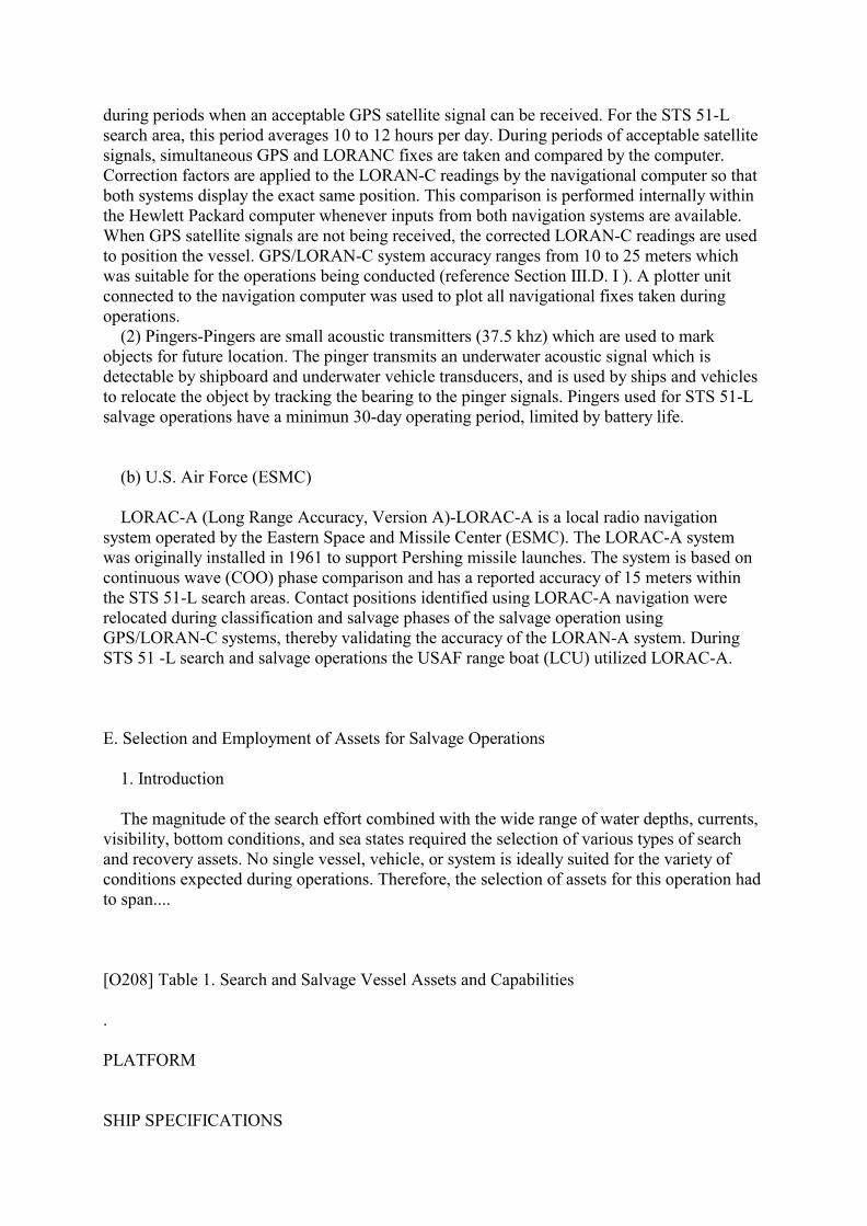
E. Selection and Employment of Assets for Salvage Operations
1. Introduction
The magnitude of the search effort combined with the wide range of water depths, currents,visibility, bottom conditions, and sea states required the selection of various types of searchand recovery assets. No single vessel, vehicle, or system is ideally suited for the variety ofconditions expected during operations. Therefore, the selection of assets for this operation hadto span....
[O208] Table 1. Search and Salvage Vessel Assets and Capabilities
.
PLATFORM
SHIP SPECIFICATIONS

SEARCH/SALVAGE ASSETS
.
FREEDOM STAR (NASA)*Searching2/8/86 - Present
Length: 176 FeetBeam: 37 FeetDraft: 12 FeetClear Deck Space: 2420 Ft2Max Speed: 17 Knots
GPS/LORAN-C NAVIGATION **Side Scanning Sonar **:-- Max Depth of 700 Feet Through 4/1/86-- Max Depth of 3,000 Feet After 4/1/86
.
LIBERTY STAR (NASA)*Searching2/8/86 - Present
Length: 176 FeetBeam: 37 FeetDraft: 12 FeetClear Deck Space: 2420 Ft2Max Speed: 17 Knots
GPS/LORAN-C NAVIGATION **Side Scanning Sonar **:-- Max Depth of 3,000 Feet
.
INDEPENDENCE (NASA)*Classification*Recovery2/8/86 - Present
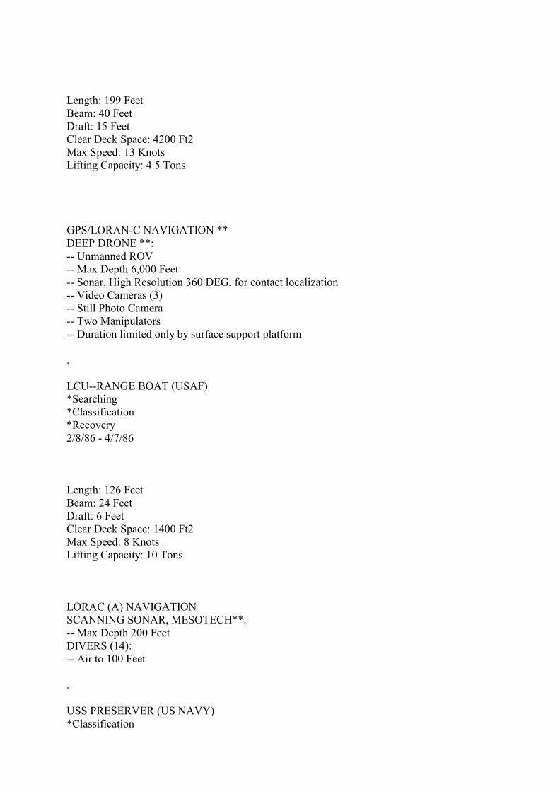
Length: 199 FeetBeam: 40 FeetDraft: 15 FeetClear Deck Space: 4200 Ft2Max Speed: 13 KnotsLifting Capacity: 4.5 Tons
GPS/LORAN-C NAVIGATION **DEEP DRONE **:-- Unmanned ROV-- Max Depth 6,000 Feet-- Sonar, High Resolution 360 DEG, for contact localization-- Video Cameras (3)-- Still Photo Camera-- Two Manipulators-- Duration limited only by surface support platform
.
LCU--RANGE BOAT (USAF)*Searching*Classification*Recovery2/8/86 - 4/7/86
Length: 126 FeetBeam: 24 FeetDraft: 6 FeetClear Deck Space: 1400 Ft2Max Speed: 8 KnotsLifting Capacity: 10 Tons
LORAC (A) NAVIGATIONSCANNING SONAR, MESOTECH**:-- Max Depth 200 FeetDIVERS (14):-- Air to 100 Feet
.
USS PRESERVER (US NAVY)*Classification

*Recovery2/8/86 - 4/11/86
Length: 201 FeetBeam: 43 FeetDraft: 13 FeetClear Deck Space: 3230 Ft2Max Speed: 14.8 KnotsLifting Capacity:-- 8 Tons Forward-- 10 Tons AftRecompression ChamberAir Diving Support System
GPS/LORAN-C NAVIGATION **DIVERS (22):-- Air Diving to 190 Feet-- Diver Held Video Camera-- Diver Held 35mm Camera
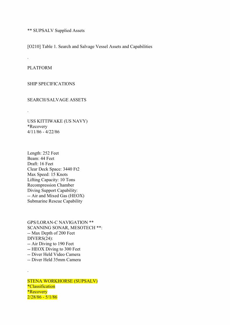
* Vessel Employment Phases** SUPSALV Supplied Assets
[O209] Table 1. Search and Salvage Vessel Assets and Capabilities
.
PLATFORM
SHIP SPECIFICATIONS
SEARCH/SALVAGE ASSETS
.
USS OPPORTUNE (US NAVY)*Classification*Recovery4/5/86 - Present

Length: 214 FeetBeam: 44 FeetDraft. 16 FeetClear Deck Space: 3440 Ft2Max Speed: 15.0 KnotsLifting Capacity:-- 20 Tons Forward-- 12 Tons AftRecompression ChamberAir Diving Support System
GPS/LORAN-C NAVIGATION **SCANNING SONAR, MESOTECH **:-- Max Depth 200 FeetDIVERS (22):-- Air Diving to 190 Feet-- Diver Held Video Camera-- Diver Held 35mm CameraSCORPI **:-- Employed 4/22/86-Present-- Unmanned ROV-- Max Depth 3000 Feet-- Forward Speed 4 Knots-- Sonar Range 4 to 400 Feet-- Video Cameras (2)-- Still Photo Camera-- One Manipulator
.
USS SUNBIRD (US NAVY)*Classification*Recovery*NR-1 Support2/20/86 - 3/18/863/31/86 - 4/17/86
Length: 252 FeetReam: 44 FeetDraft: 16 FeetClear Deck Space: 3440 Ft2Max Speed: 15 KnotsLifting Capacity: 10 TonsRecompression ChamberDiving Support Capability:-- Air and Mixed Gas (HEOX)

Submarine Rescue Capability
GPS/LORAN-C NAVIGATION **SCANNING SONAR, MESOTECH **:-- Max Depth of 200 FeetDIVERS(24):-- Air Diving to 190 Feet-- HEOX Diving to 300 Feet-- Diver Held Video Camera-- Diver Held 35mm Camera
.
NR-1 RESEARCH SUB (US NAVY)*Wide Area Search*Classification2/20/86 - 3/18/863/31/86 - 4/17/86
Length: 137 FeetBeam: 16 FeetDraft: 15 FeetClear Deck Space: N/AMax Speed:-- 4.5 Knots Surface-- 3.5 Knots SubmergedSample Collection Baskets,2Lifting Capacity:-- Manipulator, 1,000 lbs-- Object Recovery System, 500 1bs
NAVIGATION:-- Dead Reckoning w/Digital Computer (Accuracy 1.5% Distance Traveled)-- 4 Deployable Transponders (Used to mark contacts and to update location)Side Looking Sonar:-- 600 Feet Search Width With 1 Foot Resolution-- 2,400 Feet Search Width With 4 Feet ResolutionForward Looking Sonar:-- 3 to 1,500 Yard Range-- 1 to 30 Yards ResolutionSub-Bottom ProfilerEleven Video CamerasFour Still Photo Cameras
* Vessel Employment Phases
** SUPSALV Supplied Assets
[O210] Table 1. Search and Salvage Vessel Assets and Capabilities
.
PLATFORM
SHIP SPECIFICATIONS
SEARCH/SALVAGE ASSETS
.
USS KITTIWAKE (US NAVY)*Recovery4/11/86 - 4/22/86
Length: 252 FeetBeam: 44 FeetDraft: 16 FeetClear Deck Space: 3440 Ft2Max Speed: 15 KnotsLifting Capacity: 10 TonsRecompression ChamberDiving Support Capability:-- Air and Mixed Gas (HEOX)Submarine Rescue Capability
GPS/LORAN-C NAVIGATION **SCANNING SONAR, MESOTECH **:-- Max Depth of 200 FeetDIVERS(24):-- Air Diving to 190 Feet-- HEOX Diving to 300 Feet-- Diver Held Video Camera-- Diver Held 35mm Camera
.
STENA WORKHORSE (SUPSALV)*Classification*Recovery2/28/86 - 5/1/86
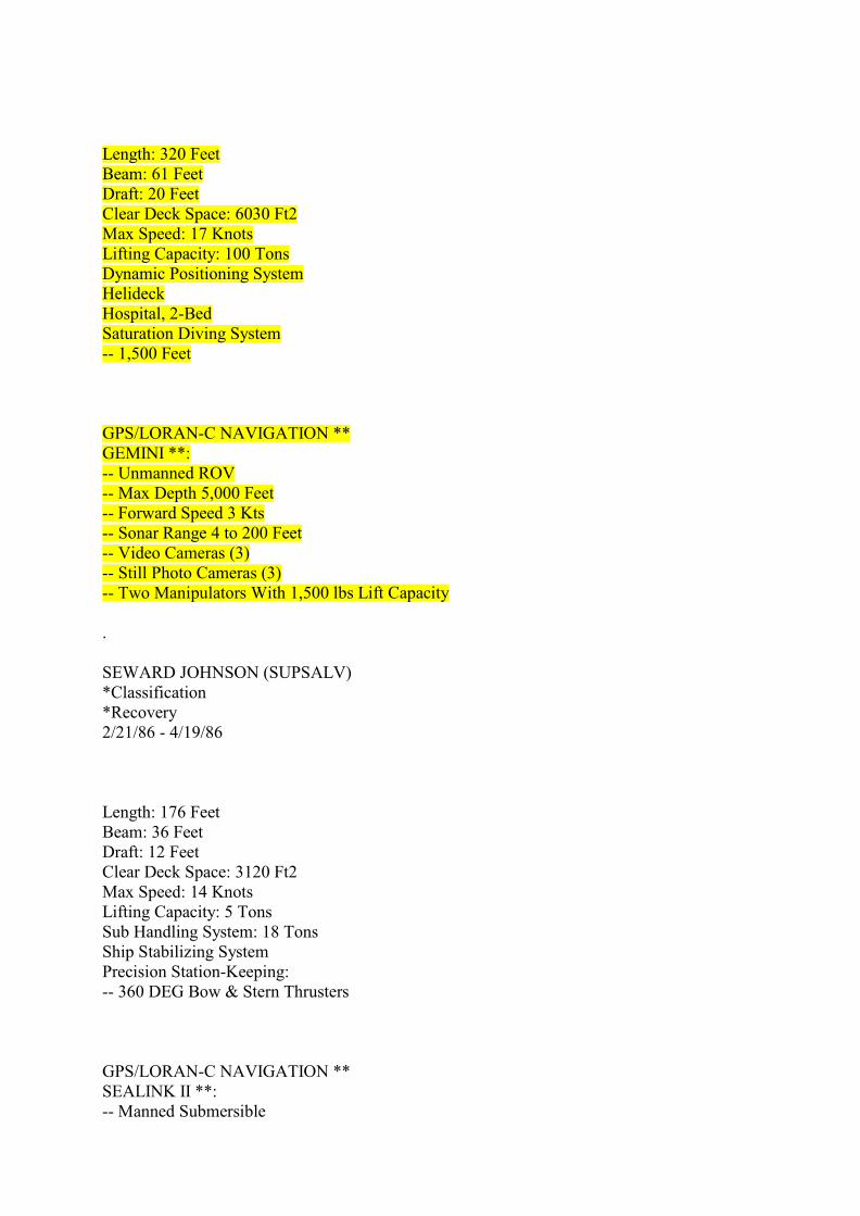
Length: 320 FeetBeam: 61 FeetDraft: 20 FeetClear Deck Space: 6030 Ft2Max Speed: 17 KnotsLifting Capacity: 100 TonsDynamic Positioning SystemHelideckHospital, 2-BedSaturation Diving System-- 1,500 Feet
GPS/LORAN-C NAVIGATION **GEMINI **:-- Unmanned ROV-- Max Depth 5,000 Feet-- Forward Speed 3 Kts-- Sonar Range 4 to 200 Feet-- Video Cameras (3)-- Still Photo Cameras (3)-- Two Manipulators With 1,500 lbs Lift Capacity
.
SEWARD JOHNSON (SUPSALV)*Classification*Recovery2/21/86 - 4/19/86
Length: 176 FeetBeam: 36 FeetDraft: 12 FeetClear Deck Space: 3120 Ft2Max Speed: 14 KnotsLifting Capacity: 5 TonsSub Handling System: 18 TonsShip Stabilizing SystemPrecision Station-Keeping:-- 360 DEG Bow & Stern Thrusters
GPS/LORAN-C NAVIGATION **SEALINK II **:-- Manned Submersible
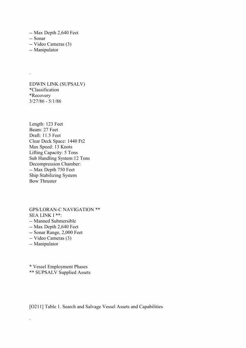
-- Max Depth 2,640 Feet-- Sonar-- Video Cameras (3)-- Manipulator
.
EDWIN LINK (SUPSALV)*Classification*Recovery3/27/86 - 5/1/86
Length: 123 FeetBeam: 27 FeetDraft: 11.5 FeetClear Deck Space: 1440 Ft2Max Speed: 13 KnotsLifting Capacity: 5 TonsSub Handling System:12 TonsDecompression Chamber:-- Max Depth 750 FeetShip Stabilizing SystemBow Thruster
GPS/LORAN-C NAVIGATION **SEA LINK I **:-- Manned Submersible-- Max Depth 2,640 Feet-- Sonar Range, 2,000 Feet-- Video Cameras (3)-- Manipulator
* Vessel Employment Phases** SUPSALV Supplied Assets
[O211] Table 1. Search and Salvage Vessel Assets and Capabilities
.

PLATFORM
SHIP SPECIFICATIONS
SEARCH/SALVAGE ASSETS
.
G.W. PIERCE II (SUPSALV)*Searching2/25/86 - 4/1/86*Recovery4/1/86 - 4/19/86
Length: 158Beam: 30 FeetDraft: 9 FeetClear Deck Space: 2390 Ft2Max Speed: 10 KnotsLifting Capacity: 10 Tons
GPS/LORAN-C NAVIGATION **Side Scanning Sonar **:-- Max Depth 3,000 Feet Through 4/1/86DIVERS (12):-- Employed 4/1/86-5/1/86-- Diver Held Video Camera-- Diver Held 35mm Camera
.
PAUL LANGEVIN III (SUPSALV)*Searching3/13/86 - Present
Length: 144 FeetBeam: 29 FeetDraft: 9 FeetClear Deck Space: 2600 Ft2Max Speed: 13 KnotsLifting Capacity: 10 Tons
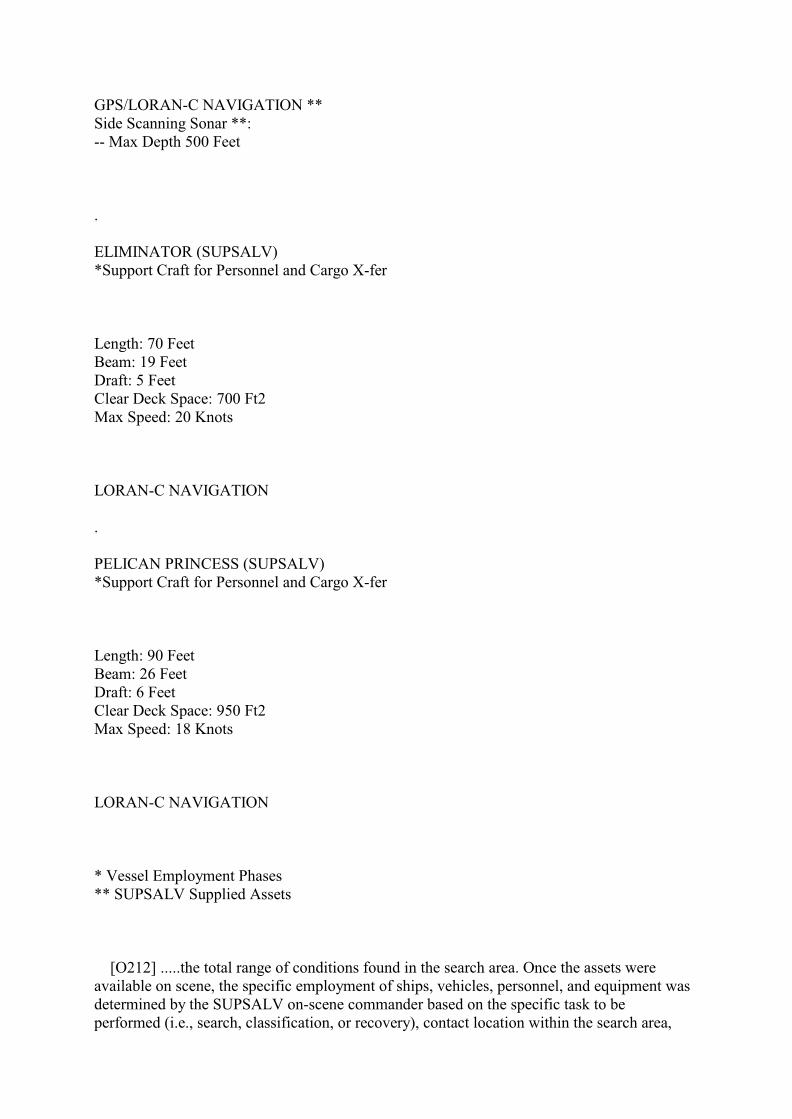
GPS/LORAN-C NAVIGATION **Side Scanning Sonar **:-- Max Depth 500 Feet
.
ELIMINATOR (SUPSALV)*Support Craft for Personnel and Cargo X-fer
Length: 70 FeetBeam: 19 FeetDraft: 5 FeetClear Deck Space: 700 Ft2Max Speed: 20 Knots
LORAN-C NAVIGATION
.
PELICAN PRINCESS (SUPSALV)*Support Craft for Personnel and Cargo X-fer
Length: 90 FeetBeam: 26 FeetDraft: 6 FeetClear Deck Space: 950 Ft2Max Speed: 18 Knots
LORAN-C NAVIGATION
* Vessel Employment Phases** SUPSALV Supplied Assets
[O212] .....the total range of conditions found in the search area. Once the assets wereavailable on scene, the specific employment of ships, vehicles, personnel, and equipment wasdetermined by the SUPSALV on-scene commander based on the specific task to beperformed (i.e., search, classification, or recovery), contact location within the search area,
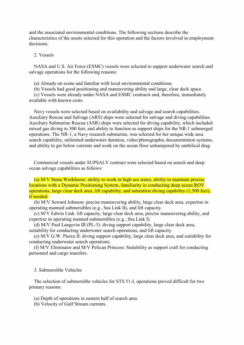
and the associated environmental conditions. The following sections describe thecharacteristics of the assets selected for this operation and the factors involved in employmentdecisions. 2. Vessels NASA and U.S. Air Force (ESMC) vessels were selected to support underwater search andsalvage operations for the following reasons:
(a) Already on scene and familiar with local environmental conditions. (b) Vessels had good positioning and maneuvering ability and large, clear deck space. (c) Vessels were already under NASA and ESMC contracts and, therefore, immediatelyavailable with known costs. Navy vessels were selected based on availability and salvage and search capabilities.Auxiliary Rescue and Salvage (ARS) ships were selected for salvage and diving capabilities.Auxiliary Submarine Rescue (ASR) ships were selected for diving capability, which includedmixed gas diving to 300 feet, and ability to function as support ships for the NR-1 submergedoperations. The NR-1, a Navy research submarine, was selected for her unique wide areasearch capability, unlimited underwater duration, video/photographic documentation systems,and ability to get below currents and work on the ocean floor unhampered by umbilical drag.
Commercial vessels under SUPSALV contract were selected based on search and deepocean salvage capabilities as follows:
(a) M/V Stena Workhorse: ability to work in high sea states, ability to maintain preciselocations with a Dynamic Positioning System, familiarity in conducting deep ocean ROVoperations, large clear deck area, lift capability, and saturation diving capability (1,500 feet),if needed. (b) M/V Seward Johnson: precise maneuvering ability, large clear deck area, expertise inoperating manned submersibles (e.g., Sea Link II), and lift capacity. (c) M/V Edwin Link: lift capacity, large clear deck area, precise maneuvering ability, andexpertise in operating manned submersibles (e.g., Sea Link I). (d) M/V Paul Langevin III (PL-3): diving support capability, large clear deck area,suitability for conducting underwater search operations, and lift capacity. (e) M/V G.W. Pierce II: diving support capability, large clear deck area, and suitability forconducting underwater search operations. (f) M/V Eliminator and M/V Pelican Princess: Suitability as support craft for conductingpersonnel and cargo transfers.
3. Submersible Vehicles The selection of submersible vehicles for STS 51-L operations proved difficult for twoprimary reasons:
(a) Depth of operations in eastern half of search area. (b) Velocity of Gulf Stream currents.

When environmental conditions permit, ROV's are normally preferred over mannedsubmersibles because of their around-the-clock operating capability. ROV's also have agreater lift capacity than manned submersibles. Numerous ROV's are available which canexceed the water depths encountered in this operation. However, most ROV's can onlyoperate in a maximum of l/2-knot current at depths greater than 1,000 feet because the powerrequirements necessary to overcome the effects of current drag on the ship-to-vehicle supportcable increase markedly with depth. Therefore, two ROV systems were initially selected toassist in the operation. The U. S. Navy's Deep Drone was assigned shallow, low current areas,and a Gemini system was utilized for the high current, deep areas. Unlike the Deep Drone, which uses a direct ship-to-vehicle cable, the Gemini can be usedwith a tether management system (TMS). With a TMS, one ROV support cable connects fromthe ship to a bottom attachment unit (BAU), and a second cable connects from the BAU to theROV. This was a significant feature since the heavy TMS BAU could be lowered to aposition near the bottom which allowed the Gemini to only pull around a short tether in thelower bottom currents. Gemini, equipped with two 40-hp hydraulic pumps, was able to workin areas with as much as 4-5 knots of surface current. A third ROV, SCORPI, was employed starting April 22, 1986. This ROV was chosen toexpedite contact classification efforts in shallow water areas with numerous contacts. Manned submersibles were selected for STS 51-L salvage operations because 1) they didnot require a tether to a surface support vessel which minimized current drag from the GulfStream, and 2) for real-time on-site observer capability which allowed NASA technicalpersonnel to view debris directly as submersible occupants and, thus, expedited contactclassification efforts. Two manned submersibles owned by the Harbor Branch Foundationwere used for STS 51-L salvage operations: Sea Link I, operating from the R/V Edwin link;and Sea Link II, operating from the R/V Seward Johnson. Both of these manned submersiblesoperated effectively at all water depths involved in the salvage operation. The significantlimitations of these systems were launch/recovery sea states (maximum 6-8 feet) and reducedbottom time (maximum 6-8 hours/day relative to ROV's. Table 1, Search and Recovery Vessel Assets and Capabilities, summarizes the overallassets available for this operation. Figure 1, STS 51-L Salvage Operation Organization, shows the command organizationrelationships and primary employment of assets.
III. SEARCH RESULTS
A. Initial Search Area
The initial search area established by SUPSALV was a parallelogram measuring 10 by 25nautical miles as shown in Figure 2. This area was chosen to be 5 nautical miles on each sideof the azimuth along which initial radar tracking analysis showed to be the major STS 51-Ldebris impact points. The water depths in the search area ranged from 70 feet of sea water(fsw) to approximately 1,200 fsw. This initial search area was west of the main axis of theGulf Stream but still within the outermost boundaries of the stream. Gulf Stream currentswere a significant handicap in conducting search operations.
B. Expanded Search Area
The initial search area was incrementally enlarged as the optical and radar data was refinedand sonar contacts were classified by divers, ROV's, and manned submersibles. A right SolidRocket Booster (SRB) debris field was found north of the initial search area and a debris fieldcontaining portions of the left SRB was located just inside the eastern edge of the initialsearch area. Further analysis of trajectory information and the location of both SRB debrisfields led to the expansion of the initial search area (Area A) to approximately 420 squarenautical miles by adding Search Area B (reference Figure 3). As the search progressed, otherareas of STS 51-L debris and potential areas for debris were identified and expanded thesearch area to 480 square nautical miles. The NR-1 conducted a large area search (3 x 20 nm)east of Area A. No SRB debris was identified in this area and, therefore, provided highconfidence that the original search area's eastern border bounded all SRB debris.
C. Search Area Contact Summary and Location of Major STS 51-L Mission Sections
Through May 1, 1986, a total of 691 contacts were identified using the side scanning sonars.The search effort in the bounded area, as shown in Figure 3, Expanded Search Area; iscomplete. The right and left SRB debris fields are located, as shown, on.....
[O213] Figure 1. STS 51L Salvage Operation Organization. Figure 1. STS 51L Salvage Operation Organization. Figure 2. Initial Search Area. Figure 2. Initial Search Area.[O214] Figure 3. Expanded Search Area. Figure 3. Expanded Search Area.
[O215] ...the eastern end of the search area. Figure 4, Search Area Display Contacts IdentifiedDuring STS 51-L Search Operations, shows the location of all sonar contacts. Many of thecontact locations defined debris fields which contained more that one and, in a few cases, upto 500 individual pieces of debris. Each debris field was assigned one contact number and allpieces in a field were listed and tracked under that contact number for management purposes.
D. Remarks on Search Operations

1. Accuracy of Sonar Located Contacts.
The actual location of the contacts identified during side scanning search operationsproved accurate to within +/- 35 meters in shallow water depths and + 100 meters in deeperwater depths. These location inaccuracies can be attributed to a combination of errors inducedby:
(a) Navigational systems.
(b) Vortex shedding due to cross currents in the water column (stronger in deeperdepths) resulting in transverse instability of the towed sonar "fish".
(c) Small variations in towing ship course, speed and ship motion (pitch and roll) due towinds and sea state, resulting in tow cable variations and additional sonar "fish" relativeposition errors.
These contact location inaccuracies were acceptable, as they were within the capabilitiesof ROV and manned submersible sonars and divers to relocate.
2. Side Scanning Sonar Remarks
(a) The tow speed of the side scanning sonar is important. If the speed is too slow, it will"slur" the trace and, if the speed is too fast, it may not adequately map ("paint") the contacts.Tow speeds of 2-4 knots are normal for side scanning sonar operations and this speed rangeproved acceptable for this operation as well. This speed is calculated with respect to thebottom (i.e., speed over ground or SOG) and not the ship's speed through the water.Therefore, a ship towing at 4 knots into a 2-knot current would only make 2 knots SOG.
(b) The stability of the towed sonar cylindrical tube, or "fish", is dependent upon itsrelative speed through the water, motion stability of the tow vessel, and cross currents. Ahigher relative speed and, therefore, more stability, is obtained by towing the "fish" into thecurrent. Given the high Gulf Stream currents in this search area, it was necessary to tow intothe current (i.e., ship heading south) most of the time. Motion stability (course, speed, pitch,and roll) of the tow vessel also affects the stability of the tow "fish." The more constant themotion stability of the vessel, the more stable the "fish" in both depth and transverseaccuracy.
(c) Since a 165-meter (122 percent) overlap of bottom area coverage was used and thecombined maximum sonar search transverse errors (detailed previously in paragraph III.D. I )were estimated to be a maximum of 100 meters, there is a high confidence that the search areabottom was fully covered. Detailed evaluation and comparison of adjacent search line bottomarea coverage sonar traces also verified full coverage was obtained (i.e., the same contactsappeared in the overlap area of adjacent traces).
IV. CONTACT CLASSIFICATION RESULTS
A. Introduction
Contact classification operations involved the collection of supporting evidence anddocumentation to determine the identity of contacts located during search operations.Supporting evidence and documentation for contact classification included: still photography,video tapes, manned submersible operator descriptions, diver descriptions, and the recoveryof small pieces of debris if they appeared to be STS 51-L related and did not require specialhandling. NASA and SUPSALV personnel reviewed and evaluated the photographs, videotapes, diver reports, and associated recovered small items of debris to positively classifycontacts. Three major classification categories were used: STS 51-L, Non-STS 51-L, andUnconfirmed. Contacts classified as STS 51-L debris were further assigned to one of thefollowing major system categories: Orbiter (including Payload), Left SRB, Right SRB,External Tank, or to Shuttle if it could not be positively linked to one of the other categories.
B. NASA Priority Assignments for Recovery
Contacts classified as STS 51-L debris were prioritized by NASA to determine the order ofrecovery. Priorities were established based on (1) importance of object recovery relative todetermining cause of mishap, and (2) humanitarian considerations. During the course of thesalvage effort, established priorities were continually reviewed and revised as additional dataand information concerning the sonar contacts was compiled. Daily meetings were convenedbetween NASA, SUPSALV, DDMS, and ESMC to review STS 51-L Salvage Operationsprogress, redefine priorities, determine the specific employment of assets, and resolvetechnical problems associated with the recovery process.
C. Summary of Classification Efforts
Of the 691 contacts located during search operations through May 1, 1986, 490 contacts havebeen classified, 82 of which were classified as STS 51-L debris. Table 2, Summary ofContacts Classified STS 51-L Debris, provides a summary of pertinent classificationinformation. Figure 5, Search Area Display of Contacts Classified STS 51-L Debris, showsthe general location of contacts from Table 2. Note that in may cases (reference Table 2), acontact defines a field (area) of contacts versus just a single contact. This tracking methodwas used in order to reduce the monitoring of contacts to a manageable level. All contactswithin a given field were normally investigated during classification operations.
D. Remarks on Classification Operations
1. Bottom Topography
Bottom topography within the search areas was a major factor with respect to theclassification of contacts. Much of the actual STS 51-L debris consisted of small pieces (e.g.,1 ft. x 1 ft. and smaller); therefore, small local natural topographic features were the primarycause for the classification of Non-STS 51-L contacts. These contacts included: conch andclam shells, fish bed holes and mounds, coral heads, and small ridges. Shells were a problemin water depths of 60 to 200 feet. Fish beds were identified in water depths of 400 to 800 feet.Coral heads were located over small areas in water depths of 60 to 200 feet. Two ridge lines
were identified, both of which run in a nearly north-south direction. One ridge line is locatedfour miles from the eastern edge of search area A in approximately 1,000 feet of water. Theother ridge line is located in the east central region of search areas A and B in 400 to 600 feetof water.
2. Discarded Equipment
The search area lies directly over a major merchant shipping lane and vessels navigatingthe area have occasionally dumped items of equipment into the ocean. Many contacts were,therefore, randomly scattered items of equipment such as 55-gallon drums, coils of wire,refrigerators, etc.
3. Aerospace Debris
Many launches have been initiated from Cape Canaveral Air Force Station (CCAFS) overthe last forty (40) years. Debris from some of these flights lies randomly within the searcharea.
4. Miscellaneous Contacts
Other contacts which were classified as Non-STS 51-L debris include planes, shipwrecks,etc.
5. General Comments
Progress in the classification of STS 51 -L contacts for recovery was tedious and slow. Thiswas due primarily to the large number of contacts involved and the high number ofpossibilities that existed within the search area for Non-STS 51-L contacts. Of the 490contacts classified, 408 contacts were Non-STS 51-L, and 82 contacts were STS 51-L related.(1 in 5).
[O216] Figure 4. Search Area Display of Contacts Identified During STS 51-L Search Operation. Figure 4. Search Area Display of Contacts Identified During STS 51-L Search Operation.[O217-O218] Table 2. Summary of Contacts Classified STS 51-L Debris. Table 2. Summary of Contacts Classified STS 51-L Debris.

[O219] Figure 5. Search Area Display of Contacts Classified STS 51-L Debris. Figure 5. Search Area Display of Contacts Classified STS 51-L Debris.
[O220] V. RECOVERY RESULTS
A. Introduction
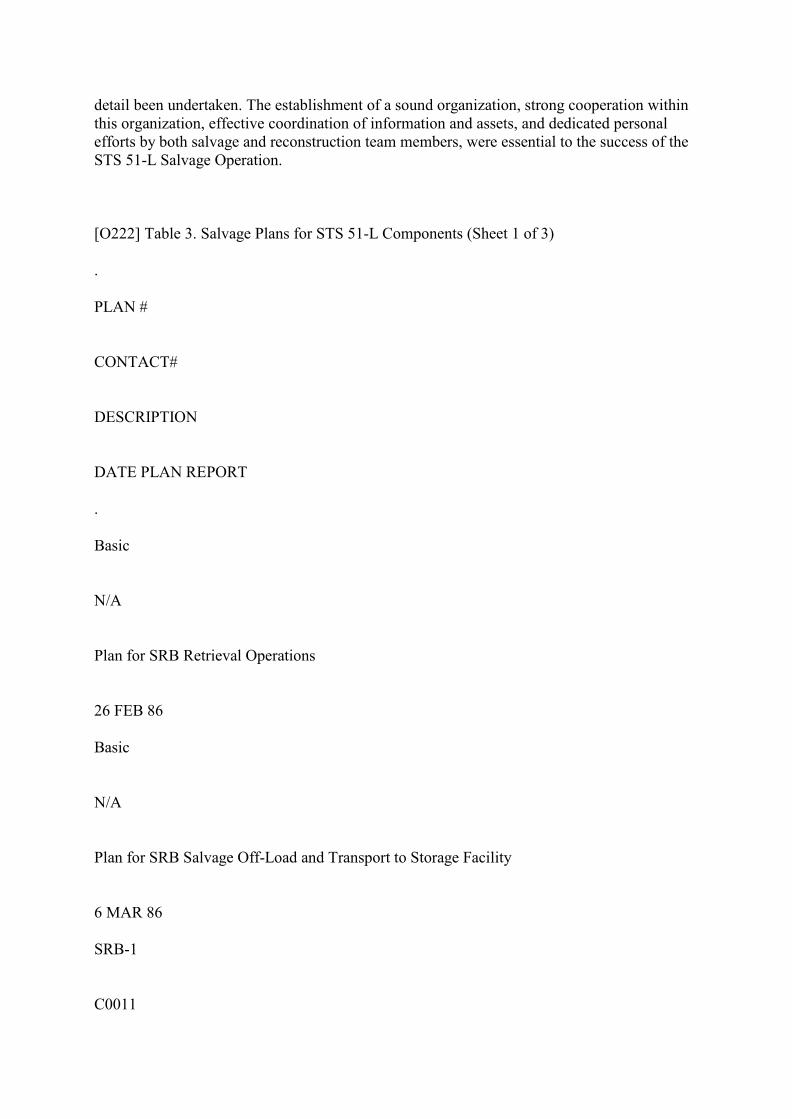
Contacts classified as STS 51-L debris was prioritized by NASA for order of recovery.Procedures for establishing priorities for recovery and coordinating asset utilization wereconducted in the same manner as previously addressed in Section IV.B. For major STS 51-Ldebris components requiring special recovery techniques, handling, and/or topside post-recovery preparations, specific salvage plans were developed. A list of salvage plans isprovided as Table 3, Salvage Plans for STS 51-L Components.
Upon completion of recovery, debris was transported from the Naval Ordinance Test Unit(NOTU) through Cape Canaveral Air Force Station (CCAFS) to Kennedy Space Center(KSC) for analysis and evaluation by the NASA Reconstruction Teams and NationalTransportation Safety Board (NTSB) members.
B. Summary of STS 51-L Underwater Recovery Operations
A total of 62 individual STS 51-L objects or groups of objects were recovered from the oceanfloor through May 1, 1986, 34 of which were SRB debris. Table 4, Summary of UnderwaterSTS 51-L Contacts Recovered, is provided as a listing of recovered STS 51-L debris. Figure6, Search Area Display of Salvaged STS 51-L Debris, provides the general location ofrecovered contacts.
C. Remarks on Recovery Operations
1. Divers
Divers were used extensively for recovery operations in shallow water area, (70-300 feet).Surface-supplied air, surface-supplied mixed gas (helium/oxygen), and scuba diving wereconducted. Divers proved to be effective for the recovery of debris in shallow areas, wherelow ocean bottom visibility often imposes an operational limitation on the use of ROV's. Theability of divers to "work by feel" also proved advantageous for the recovery of items in theshallow areas where visibility was frequently less than one foot.
2. Remotely Operated Vehicles (ROV's)

Strong currents throughout the water column and occasional poor visibility limited the useof the Deep Drone. The Deep Drone was an effective asset when current conditions andvisibility allowed employment. The Gemini proved to be very effective working in deeperdepths and higher currents. Gemini utilized a two-cable configuration with a heavydepressor/tether winch module (TMS). The TMS was lowered to operating depth andprovided additional weight to stabilize the main umbilical below the support ship. Itdecoupled the vehicle from umbilical drag and motion. The work vehicle was then free tomaneuver via a 500-foot vehicle tether. The SCORPI was an efficient vehicle for classifyingcontacts in shallow water areas.
3. Manned Submersibles
Manned submersibles, which are not tethered, operate independent of the surface supportship and are very effective for operating on the bottom. These vehicles were most effective inthe classification of contacts in the high surface current areas. Manned submersibles,however, are limited to operational periods of 6 to 8 hours/day. Furthermore, mannedsubmersibles do not have sufficient power to lift heavy objects nor can they be easily used toattach lift lines since there is a possibility of entanglement, thus endangering the crew.
4. NR-1
This research submarine proved to be a very effective and efficient asset. The NR-1operated during the most severe environmental conditions, stayed submerged for extendeddurations, and conducted wide area searches. The use of this asset resulted in the location andclassification of many contacts in a relatively short period of time so that recovery effortsprogressed more effectively.
5. Effects of Environment
Environmental factors were the major obstacles during this salvage operation. Weathersystems resulting in high sea states and water turbidity contributed to lost time due to inabilityto launch and retrieve assets and loss of underwater visibility. The effects of currents at alllocations in the water column severely hindered the operations of the divers, ROV's, mannedsubmersibles, and side scanning sonar. Silt buildup, as much as two feet in some areas,severely reduced the ability to locate and recover debris. Because of these environmentalconditions, a large number of assets were employed, thereby avoiding extension of theoperation over a longer time period.
6. Random Scatter of Components
During most salvage operations, the location of the various debris components involvedbecomes clearer as contacts are located, classified, and recovered. Due to the nature of thismishap, the location of debris components which were classified and recovered was random.
Structurally adjacent components of the right SRB were found separated by as much as fivemiles. Figure 7 shows the locations of recovered right SRB debris. The associated numbersshow the assigned salvage contact number for each recovered piece of debris. Figure 8illustrates the magnitude of the scatter problem.
7. Position Accuracy of Recovered Components
The position accuracy of recovered components was dependent upon the navigationalaccuracy of the recovery ship and the relative position accuracy of the component withrespect to the ship. The primary navigation system used by ships conducting recoveryoperations was GPS/LORAN-C. The accuracy of GPS/LORAN-C was 10 to 25 meters,dependent upon whether fixes were based on satellite signals or compared/corrected LORAN-C signals. The relative position of the component with respect to the recovery ship wasdetermined by several methods. Methods included the use of: pingers placed on the contact todetermine relative position, ROV or manned submersible-to-ship relative positioning systems,and direct ship-to-component wire cable(s). Dependent upon the method used and the waterdepth, the ship-to-component relative position accuracy ranged from 10 to 25 meters.Recorded component position accuracy ranged from +/-35 meters in shallow water and +/- 50meters in deep water.
VI. CLOSING REMARKS
The proper employment, utilization, and coordination of available assets was essential to thesuccessful salvage of STS 51-L debris. Concurrent search, identification, and recoveryoperations usually involved the use of several assets to affect recovery of a single object. Agood example is Contact #131 which is the right SRB aft center segment containing the tangportion of the suspect joint burn through area. This contact was initially located on March I,1986, by the M/V Liberty Star using side scanning sonar in 560 feet of water. NR-1 operatedat the site of Contact #131 on April 5, 1986, classified the item as possible STS 51-L debris,and video taped the contact. After review of the NR-1 video tape, the manned submersible,Sea Link I, operating from the R/V Edwin Link, was assigned to investigate the contact andobtain higher-quality video. On a dive conducted April 12, 1986, the Sea Link I on-boardobservers verified that Contact #131 was debris from the right SRB and included the tangportion of the joint area in question. Based on the physical size and weight of the debris, theM/V Stena Workhorse was assigned to conduct recovery. Utilizing the ROV Gemini, the M/VStena Workhorse attached a lift line to the debris and recovered it on April 13, 1986.Therefore, the salvage of this single contact involved three surface vessels, a side scanningsonar, a research submarine, a manned submersible, an ROV, and heavy-lift crane.
The salvage of STS 51-L debris was unique due to the large geographic size (480 squarenautical miles) of the search area, the small size of much of the debris being sought, the largenumber of contacts requiring investigation, and the random dispersion of STS 51-L on theocean bottom. Environmental conditions within the search area were severe and varied, andoften reduced, or even totally curtailed, the operational effectiveness of the STS 51-L salvageoperations. These environmental conditions, coupled with the enormity of scope of thisoperation, necessitated [O221] the simultaneous employment of many different types andnumbers of assets. Never before has a massive search and salvage operation of this scope and
detail been undertaken. The establishment of a sound organization, strong cooperation withinthis organization, effective coordination of information and assets, and dedicated personalefforts by both salvage and reconstruction team members, were essential to the success of theSTS 51-L Salvage Operation.
[O222] Table 3. Salvage Plans for STS 51-L Components (Sheet 1 of 3)
.
PLAN #
CONTACT#
DESCRIPTION
DATE PLAN REPORT
.
Basic
N/A
Plan for SRB Retrieval Operations
26 FEB 86
Basic
N/A
Plan for SRB Salvage Off-Load and Transport to Storage Facility
6 MAR 86
SRB-1
C0011

Plan for Left Hand SRB Aft Segment/ET Attach Ring Segment Retrieval Operations
26 FEB 86
SRB-2
C0026 (TAR #26-1)
Plan for Left Hand SRB Aft Center Segment/Fwd Case Segment Retrieval Operations
3 MAR 86
SRB-3
C0026 (TAR #26-2)
Plan for Left Hand SRB Aft Center Segment/Fwd Case Segment Retrieval Operations
3 MAR 86
Adden. No. 1
C0001
Addendum No. I (R.H. SRB Aft Seg/ Dome Stiffener Seg) to Requirements for 51-L SRBRetrieval Operations
6 MAR 86
Adden. No. II
C0021
Addendum No. II (SRB Case Tang Segment) to Requirements for 51-L SRB RetrievalOperations
7 MAR 86

Adden. No. III
C0021
Addendum No. III (SRB Aft Seg/ Stiffener/Stiffener with Tunnel Segment) to Requirementsfor 51-L SRB Retrieval Operations
7 MAR 86
Adden. No. IV
C0021
Addendum No. IV (SRB Aft Seg/Stiffener Segment with Clevis) to Requirements for 51-LSRB Retrieval Operations
7 MAR 86
Adden. No. V
C0024
Addendum No. V (L.H. SRB Aft Seg/ Dome/Kick Ring) to Requirements for 51-L SRBRetrieval Operations
12 MAR 86
Adden. No. VI
C0041
Addendum No. VI (SRB Fwd Seg Dome/Igniter) to Requirements for 51-L SRB RetrievalOperations
13 MAR 86
Adden. No. VII
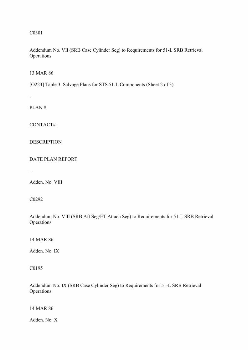
C0301
Addendum No. VII (SRB Case Cylinder Seg) to Requirements for 51-L SRB RetrievalOperations
13 MAR 86
[O223] Table 3. Salvage Plans for STS 51-L Components (Sheet 2 of 3)
.
PLAN #
CONTACT#
DESCRIPTION
DATE PLAN REPORT
.
Adden. No. VIII
C0292
Addendum No. VIII (SRB Aft Seg/ET Attach Seg) to Requirements for 51-L SRB RetrievalOperations
14 MAR 86
Adden. No. IX
C0195
Addendum No. IX (SRB Case Cylinder Seg) to Requirements for 51-L SRB RetrievalOperations
14 MAR 86
Adden. No. X
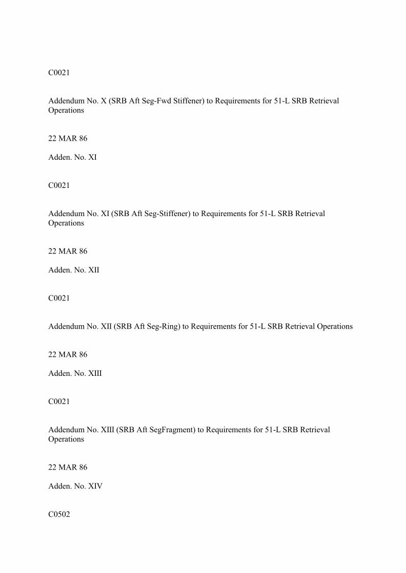
C0021
Addendum No. X (SRB Aft Seg-Fwd Stiffener) to Requirements for 51-L SRB RetrievalOperations
22 MAR 86
Adden. No. XI
C0021
Addendum No. XI (SRB Aft Seg-Stiffener) to Requirements for 51-L SRB RetrievalOperations
22 MAR 86
Adden. No. XII
C0021
Addendum No. XII (SRB Aft Seg-Ring) to Requirements for 51-L SRB Retrieval Operations
22 MAR 86
Adden. No. XIII
C0021
Addendum No. XIII (SRB Aft SegFragment) to Requirements for 51-L SRB RetrievalOperations
22 MAR 86
Adden. No. XIV
C0502

Addendum No. XIV (SRB Cyl SegFld Joint Tang) to Requirements for 51-L SRB RetrievalOperations
25 MAR 86
Adden. No. XV
C0325
Addendum No. XV (SRB Case CylClevis Joint) to Requirements for 51-L SRB RetrievalOperations
25 MAR 86
Adden. No. XVI
C0021 (TAR #29-1)
Addendum No. XVI (SRB Case CylClevis and Tang Joint) to Require meets for 51-L SRBRetrieval Operations
29 MAR 86
Adden. No. XVII
C0214 (TAR #214)
Addendum No. XVII (SRB Case Segment) to Requirements for 51-L SRB RetrievalOperations
3 APR 86
Adden. No.XVIII
C0615 (TAR#615-1)
Addendum No. XVIII (SRB Case CylTang) to Requirements for 51-L SRB RetrievalOperations

4 APR 86
Adden. No. XIX
C0615 (TAR#615-2)
Addendum No. XIX (SRB Case CylClevis) to Requirements for 51-L SRB RetrievalOperations
4 APR 86
[O224] Table 3. Salvage Plans for STS 51-L Components (Sheet 3 of 3)
.
PLAN #
CONTACT#
DESCRIPTION
DATE PLAN REPORT
.
Adden. No. XX
C0345, C0417, C0487,C0632
Addendum No. XX (SRB Hardware) to Requirements for 51-L SRB Retrieval Operations
17 APR 86
Adden. No. XXI
C0579
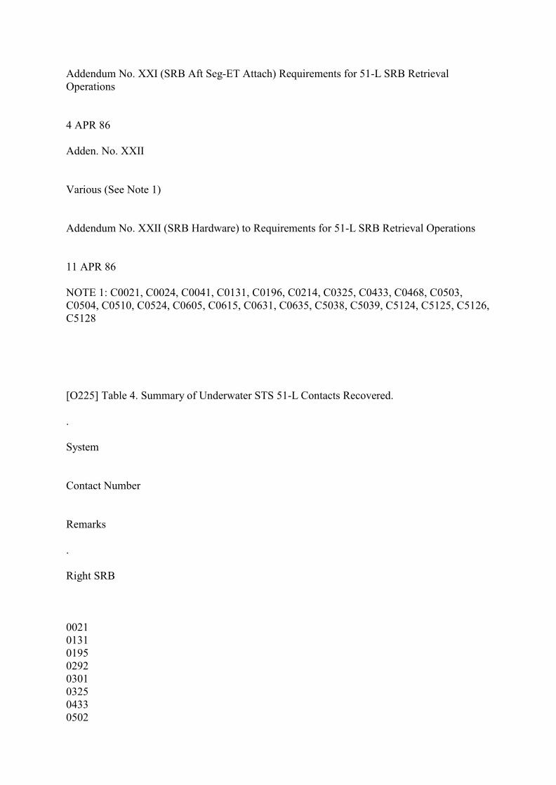
Addendum No. XXI (SRB Aft Seg-ET Attach) Requirements for 51-L SRB RetrievalOperations
4 APR 86
Adden. No. XXII
Various (See Note 1)
Addendum No. XXII (SRB Hardware) to Requirements for 51-L SRB Retrieval Operations
11 APR 86
NOTE 1: C0021, C0024, C0041, C0131, C0196, C0214, C0325, C0433, C0468, C0503,C0504, C0510, C0524, C0605, C0615, C0631, C0635, C5038, C5039, C5124, C5125, C5126,C5128
[O225] Table 4. Summary of Underwater STS 51-L Contacts Recovered.
.
System
Contact Number
Remarks
.
Right SRB
00210131019502920301032504330502
0538057906150712
Aft Segment SkirtAft Center Segment w/Burn AreaForward Aft Center SegmentForward Aft SegmentAft Forward SegmentAft Center SegmentAft Center SegmentForward Center SegmentForward Skirt and ParachuteAft SegmentForward Center SegmentAft Segment w/Burn Area
Orbiter
000800100023003000660068007100720077007801920520053005550558056405660567056805720595************

Hydraulic LinesEngine PartsEngine Parts3' Cable Tray ExitMain Orbiter Engine NozzleAft FuselageMiscellaneous Small HardwareMiscellaneous Medium HardwareMedium Sidewall PieceMedium Cone ShapeLarge Hydrazine TankLeft Aft FuselageVertical StabilizerExternal Large PieceEngine NozzleAft Cargo HoldRight WingElectronics and WiringLeft Fuselage SidewallExternal Medium PieceLarge Left Wing PieceCrew CompartmentOrbiter CargoOrbiter Cargo
Left SRB
001100265124
Forward Aft SegmentForward Aft Center SegmentSRB External Tank Strut
External Tank
000300040029
External Small Pieces
External Medium PieceExternal Large Piece
[O226] Booster,Unknown Side
0196021403120468048705100524060506310635069907115038053951255126512751285433
External Tank Attachment w/Clevis Large Curved External PieceLarge External PieceLarge External PieceLarge External Piece w/ClevisLarge External PieceLarge External PieceMedium External PieceMedium External Piece w/Clevis and TangForward Motor CasingForward SegmentMedium External PieceLarge External Piece w/ClevisLarge External Piece w/TangMedium External PieceMedium External Pieces (3)Large External/Internal PieceMedium External PieceMedium Motor Skin Piece
[O227] Figure 6. Search Area Display of Salvaged STS 51-L Debris.

Figure 6. Search Area Display of Salvaged STS 51-L Debris. [O228] Figure 7. RH SRB Located Debris. Figure 7. RH SRB Located Debris. [O229] Figure 8. RH SRB Locations. Figure 8. RH SRB Locations.
Appendix O (Enclosure 3) | Appendix O | Appendix O (Enclosure 5)