Embed Size (px)
Citation preview
Report of Geotechnical Engineering Services Runway and Taxiway Extension Atlanta South Regional Airport
Henry County, Georgia ATC Project Number 066.42492.5994
Prepared For:
Croy Engineering, LLC 200 North Cobb Parkway Building 400, Suite 413
Marietta, Georgia 30062
Ms. Rebecca M. Collins, PE
September 28, 2012
5994 Atl South Reg Airport Geo Rpt-Rev0.docx REV-0
TABLE OF CONTENTS
SECTION PAGE 1.0 INTRODUCTION ..................................................................................................................... 1 1.1 Project Information .................................................................................................. 1 1.2 Purpose and Scope of Evaluation ........................................................................... 1 2.0 EXPLORATION PROCEDURES ........................................................................................... 3 2.1 Site Reconnaissance .............................................................................................. 3 2.2 Field Exploration ..................................................................................................... 3 2.3 Laboratory Testing .................................................................................................. 4 3.0 SITE AND GENERAL SUBSURFACE CONDITIONS ....................................................... 5 3.1 Site Description ....................................................................................................... 5 3.2 Area and Site Geology ............................................................................................ 5 3.3 General Subsurface Conditions .............................................................................. 5 3.4 Laboratory Testing Results ..................................................................................... 6 4.0 CONCLUSIONS AND RECOMMENDATIONS ..................................................................... 7 4.1 General ................................................................................................................... 7 4.2 Site and Subgrade Preparation ............................................................................... 7 4.3 Groundwater Conditions ......................................................................................... 7 4.4 Excavation Conditions ............................................................................................ 7 4.5 Structural Fill ........................................................................................................... 8 4.6 Pavement Design ................................................................................................... 8 4.7 Retaining/Below Grade Walls ................................................................................ 13 5.0 QUALIFICATIONS OF RECOMMENDATIONS .................................................................. 15 APPENDIX Field Exploration Plan Test Boring Records (11) Results of Asphalt Cores – Existing Runway Pavement Summary of Hand Auger Borings Summary of Pavement Condition Index (PCI) Survey – Existing Runway Pavement Photographs from PCI Survey of Existing Runway Bearing Ratio Test Report Modified Proctor Test Report Atterberg Limits Test Results Particle Size Distribution Report Key Symbol Sheet Soil Classification Chart ASFE Information about Your Geotechnical Report
5994 Atl South Reg Airport Geo Rpt-Rev0.docx REV-0 1
REPORT OF GEOTECHNICAL ENGINEERING SERVICES
RUNWAY AND TAXIWAY EXTENSION ATLANTA SOUTH REGIONAL AIRPORT
HENRY COUNTY, GEORGIA ATC PROJECT NUMBER 066.42492.5994
1.0 INTRODUCTION 1.1 Project Information
Our understanding of the project is based upon the provided site plan and information communicated in various emails. We understand that the Atlanta South Regional Airport, formerly known as Tara Field, is planning an extension of the existing runway and adjoining taxiway in order to accommodate larger and heavier aircraft. The proposed construction consists of a 1000-foot runway extension off the northeast end of the runway. The taxiway will also be extended accordingly. The existing runway will be widened to 100 feet in order to accommodate the larger and heavier aircraft. Furthermore, the ability of the existing runway pavement to accommodate the heavier aircraft is to be evaluated. According to the most current FAA Form 5010-1 for the airport, aircraft operations are estimated to be 42,000 per year. This corresponds to 21,000 departures per year. The existing runway is 4,503 feet long by 75 feet wide and constructed of asphalt. The taxiway and apron areas are also constructed of asphalt. The runway is designed to accommodate aircraft with gross weights of 30,000 lbs (single wheel) and 45,000 lbs (double wheel). No information regarding future aircraft loading conditions, such as the types of aircraft utilizing the runway, the anticipated number of departures per year per aircraft, the anticipated yearly growth rate in departures, the gross weight of the aircraft, etc., has been provided at this time. We have therefore made some assumptions based upon available information regarding future aircraft traffic. We understand that if the existing runway slope is held at +0.8% for the 1,000-foot extension, the end of the runway would be at about elevation 881.5 feet. Based upon existing grades, cuts on the order of 10 feet are anticipated. Some fills on the order of 5 feet may be necessary in the taxiway area.
1.2 Purpose and Scope of Evaluation
The purpose of our services was to explore subsurface soil conditions at the project site and to provide geotechnical recommendations for project design and construction. The scope of work included a site reconnaissance, soil test boring and sampling, hand auger
5994 Atl South Reg Airport Geo Rpt-Rev0.docx REV-0 2
boring, asphalt coring, laboratory testing, engineering evaluation of the field and laboratory data, and the preparation of this report. The services were provided in general accordance with our Proposal Number 66.2012.0178 dated May 17, 2012. Specifically, the scope of work addressed the following items:
• Soil nature and origin, including changes resulting from man’s activities. • Depths, thicknesses, composition of soil strata that will be appreciably stressed by
the intended construction. • Depths to encountered groundwater, dense soil strata, and rock that could affect the
proposed construction. • Recommendations pertaining to the planned runway and taxiway extension,
including site preparation, earthwork construction, groundwater control, excavation slopes, unsuitable material, and difficult excavation.
• Evaluation of existing runway pavement based upon provided aircraft loads. • Pavement recommendations for the runway extension based upon a laboratory CBR
value and provided aircraft loads. • Discussion of other geotechnical related items identified during the exploration.
The scope of our services did not include any environmental assessment or investigation
for the presence or absence of hazardous or toxic materials in the soil, groundwater, or surface water within or beyond the site. Any statements in this report or on the Test Boring Records regarding odors, staining of soils, or other unusual conditions observed are strictly for the information of our client.
5994 Atl South Reg Airport Geo Rpt-Rev0.docx REV-0 3
2.0 EXPLORATION PROCEDURES 2.1 Site Reconnaissance Prior to the field exploration, the site and surrounding areas were observed by an engineer
from our office. The observations were used in planning this exploration and in determining areas of special interest.
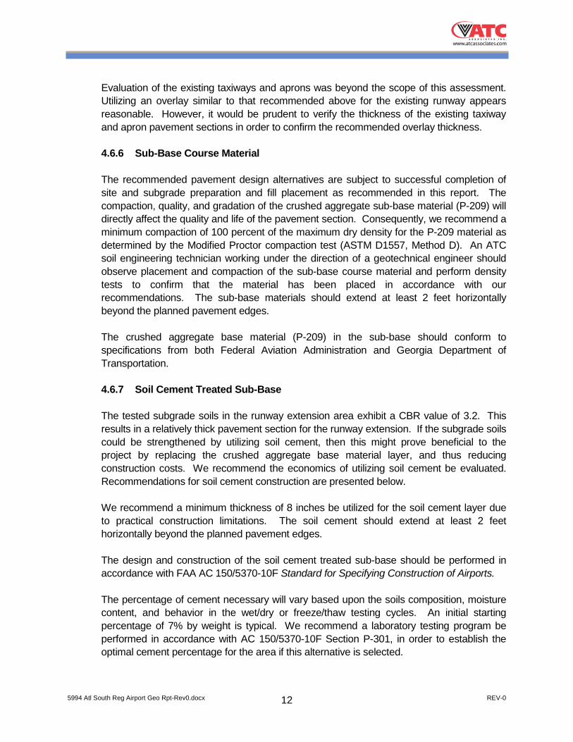
2.2 Field Exploration Eleven soil test borings, designated B-1 through B-11, were drilled to explore subsurface
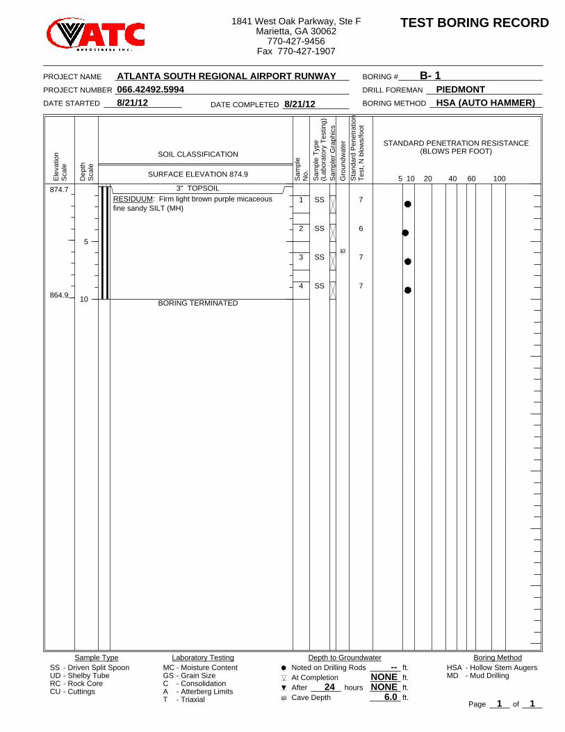
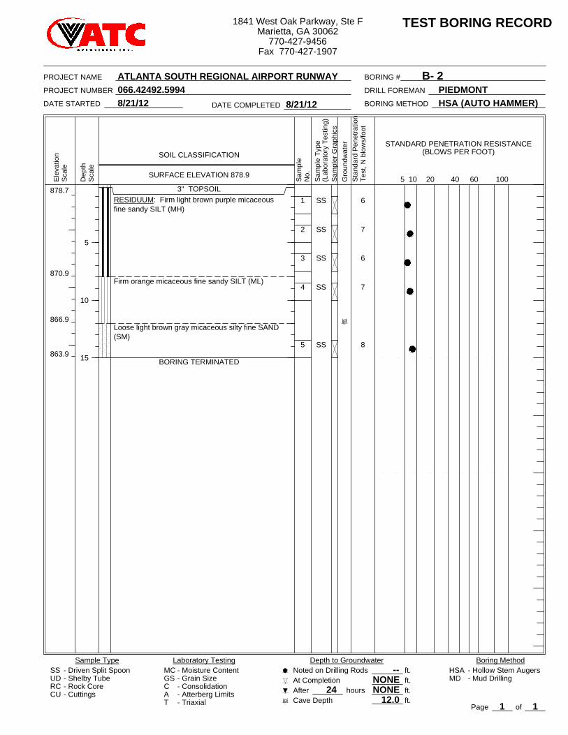
conditions at the site. The approximate locations of the borings are shown on the Field Exploration Plan in the Appendix. All borings were extended to boring termination at depths ranging from 10 to 25 feet below the existing ground surface. Test Boring Records that graphically depict soil descriptions, penetration resistances and observed groundwater levels are included in the Appendix.
The borings locations were selected by ATC personnel and established in the field Croy
Engineering personnel utilizing survey techniques. Elevations on the Test Boring Records were obtained by survey techniques.
All soil sampling and standard penetration testing were performed in general accordance
with ASTM Method D1586. The soil test borings were advanced by mechanically turning hollow-stem augers into the soil. At regular intervals, soil samples were obtained with a standard 1.4-inch I.D., 2.0-inch O.D., split-barrel sampler. The sampler was first seated 6 inches and then driven an additional foot with blows of a 140-pound hammer falling 30 inches. The number of blows required to drive the sampler the final foot was recorded and is designated the “standard penetration resistance.” Penetration resistance, when properly evaluated, is an index of the soil’s strength and support capability.
All the borings were drilled using an Automatic Hammer to drive the split-spoon sampler.
The Automatic Hammer is more efficient than the traditional safety hammer and imparts more energy to the split spoon sampler. Thus the resistance values are slightly lower than the traditional rope-cathead equipment. The type of hammer used is noted on the Test Boring Records.
Representative portions of the soil samples obtained with the split-barrel sampler were
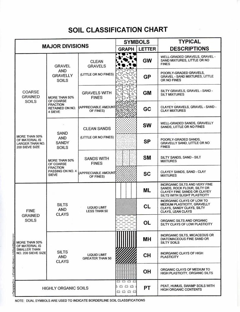
sealed in glass jars and transported to our laboratory. In the laboratory, they were examined by a geotechnical engineer and classified in general accordance with the Unified Soil Classification System. The soil descriptions and classifications are based on visual examination and should be considered approximate. Bulk samples of the materials encountered in soil test borings B-1 through B-5 were obtained for laboratory testing.
Coring of the asphalt was performed at 10 selected locations in the existing runway to
assess the pavement section thickness. The cores were backfilled and patched with asphalt upon completion. The approximate locations of the cores are shown on the Field
5994 Atl South Reg Airport Geo Rpt-Rev0.docx REV-0 4
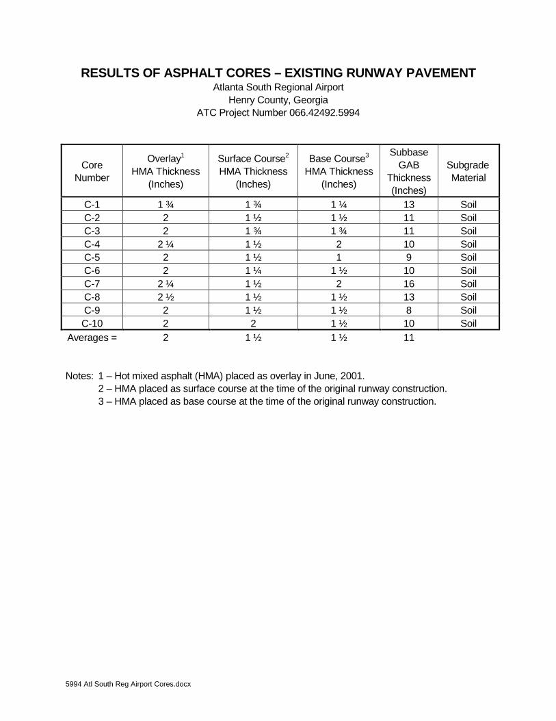
Exploration Plan in the Appendix. The results of the asphalt cores are presented in the table titled Results of Asphalt Cores – Existing Runway Pavement presented in the Appendix.
Hand auger borings were performed at 5 selected locations along the edge of the existing runway to assess the soil subgrade conditions. The hand auger borings were made by manually rotating a sharpened steel bucket auger into the soil. The borings were extended to depths of 4 feet below the existing ground surface. Soil cuttings were examined and classified by an engineer in the field using the Unified Soil Classification System. At regular intervals in the hand auger borings, the soil consistency was measured with a portable dynamic cone penetrometer. After first seating the conical point, the point was driven an additional 1 ¾ inches with blows of a 15-pound hammer falling 20 inches. The number of blows required to achieve this penetration was recorded. This gives an index of the soil's strength and compressibility. The hand auger borings were backfilled with auger cuttings upon completion. The approximate locations of the hand auger borings are shown on the Field Exploration Plan in the Appendix. The results of the hand auger borings are presented in the table titled Summary of Hand Auger Borings in the Appendix.
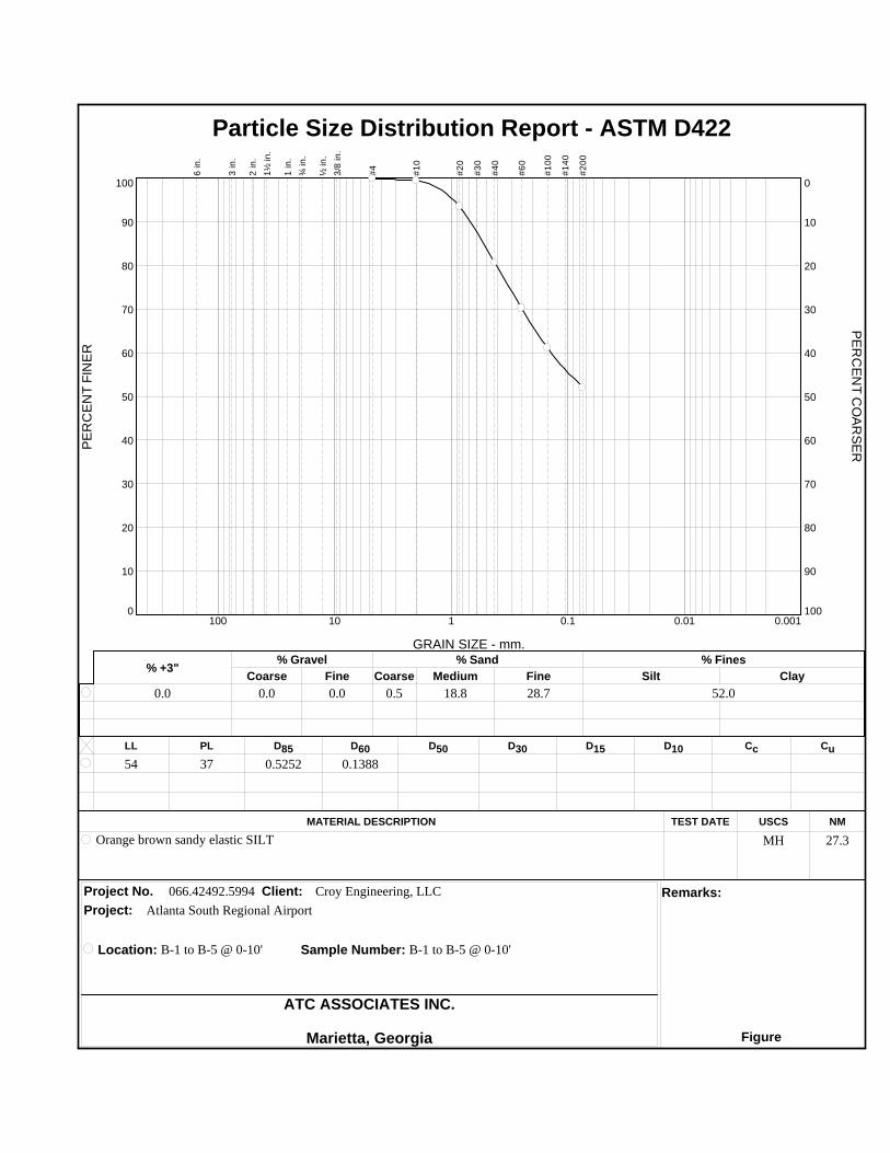
2.3 Laboratory Testing Classification tests consisting of Particle Size Distribution (ASTM D422) and Atterberg
Limits (ASTM D4318) were performed on the composite bulk samples obtained from Borings B-1 through B-5. The test results are presented in the Appendix.
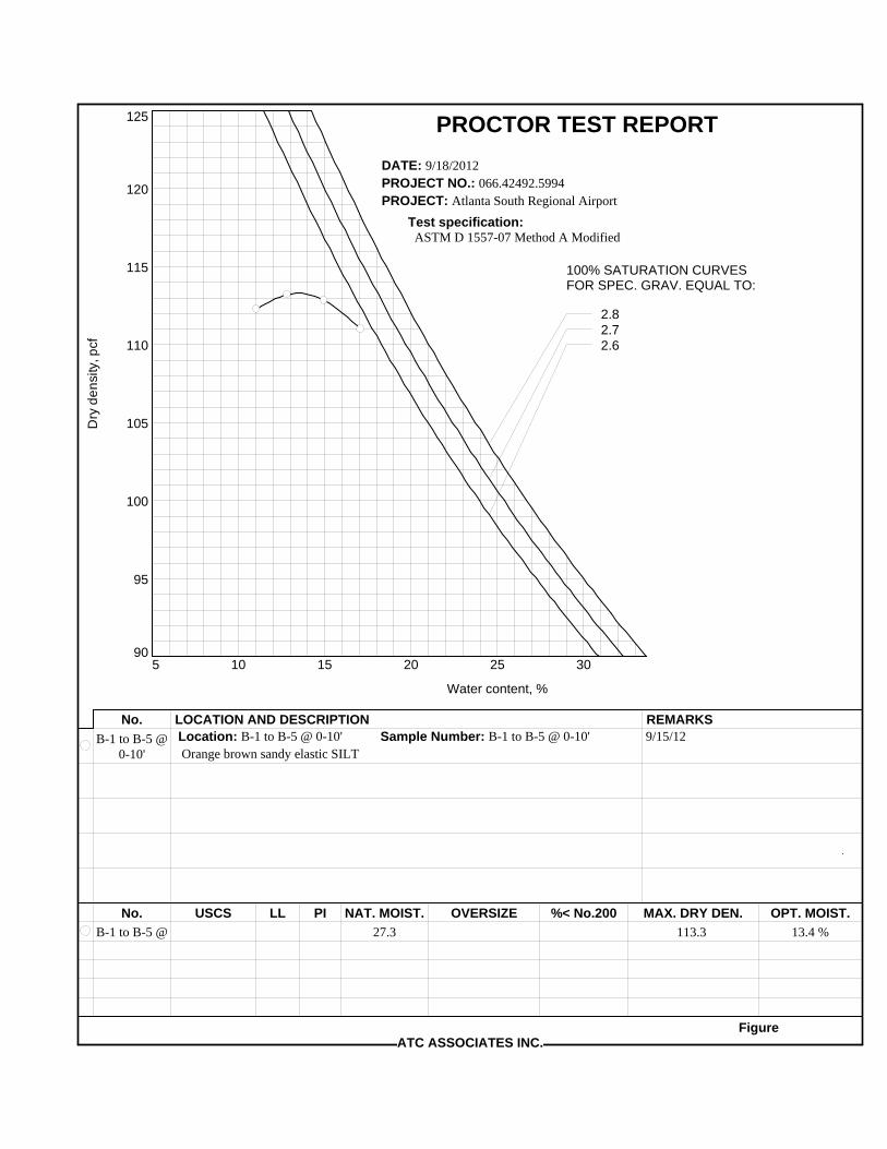
Soil compaction testing was performed on the composite bulk soil samples obtained from
Borings B-1 through B-5. The compaction test determines the dry density produced by a uniform compactive effort at varying moisture contents. The compaction tests were performed in accordance with ASTM specification D1557 (Modified Proctor). The test results are presented in the Appendix.
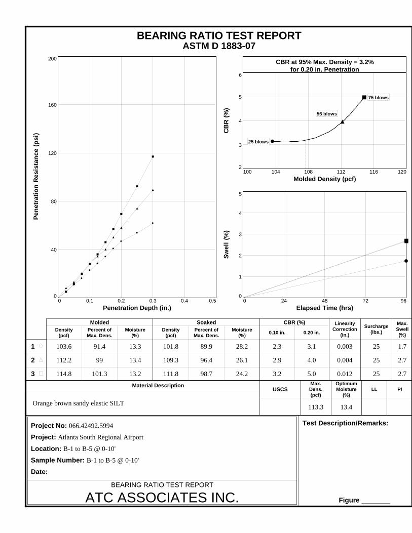
California Bearing Ratio (CBR) testing was performed on the bulk sample in accordance
with ASTM D1883. The CBR is a punching shear test. It provides data that is a semi-empirical index of the strength and deflection characteristics of a soil correlated with pavement performance to establish design curves for pavement thickness. The test is performed on a 6-inch diameter, 5-inch thick sample of compacted soil confined in a steel cylinder. Before testing, the sample is soaked in water under a confining pressure roughly equivalent to the weight of the future pavement to determine the potential swelling and to simulate the subgrade saturation in the field. A 1.95 inch diameter piston is then forced into the soil at a standard rate to determine the resistance to penetration. The CBR is the ratio, expressed as a percentage, of the load required to produce a 0.1-inch or 0.2-inch deflection of the test soil to that required to produce the same deflection in a standard crushed stone. The result of the CBR test is included in the Appendix.
5994 Atl South Reg Airport Geo Rpt-Rev0.docx REV-0 5
3.0 SITE AND GENERAL SUBSURFACE CONDITIONS 3.1 Site Description
The site of the proposed construction is located at the Atlanta South Regional Airport, previously known as Tara Field, in Henry County, Georgia. The construction will be located off the northeast end of the runway and taxiway. The area is currently covered with grass. The ground surface elevation along the runway extension alignment ranges from about 874 feet at the end of the existing runway to about 893 feet near Mount Pleasant Road road. The ground surface elevation along the taxiway extension varies from about 872 to 883 feet.
3.2 Area and Site Geology The site is located in the Piedmont Physiographic Province, an area underlain by ancient
igneous and metamorphic rocks. The upland soils in this area are the residual product of in-place weathering of the parent rock. A typical residual soil profile consists of clayey soils near the surface, where soil weathering is more advanced, underlain by sandy silts and silty sands that generally become less weathered and denser with depth to the top of parent bedrock. The boundary between soil and rock is usually not clearly defined.
A transitional zone called “partially weathered rock” is normally found above the parent
bedrock. Partially weathered rock is defined for engineering purposes as residual material with standard penetration resistances in excess of 100 blows per foot and which can be penetrated by soil drilling equipment. Weathering is facilitated by fractures, joints, and the presence of less resistant rock types. Consequently, partially weathered rock and the hard rock profiles are irregular, and zones of partially weathered rock or rock may occur within the soil mantle well above the general bedrock level.
3.3 General Subsurface Conditions Data from the soil test borings are shown on the Test Boring Records in the Appendix.
The subsurface conditions discussed in the following paragraphs and those shown on the Test Boring Records are based on the soil test borings drilled at the site and represent an estimate of the subsurface conditions based on interpretation of the boring data using normally accepted geotechnical engineering judgments. Although individual test borings are representative of the subsurface conditions at the boring locations on the dates shown, they are not necessarily indicative of subsurface conditions at other locations or at other times. We note that the transition between different soil strata is generally less distinct than those shown on the Test Boring Records.
3.3.1 Surficial Materials
Topsoil is a dark-colored surficial material with a high organic content that is generally unsuitable for structural support. Topsoil was encountered in all the borings except B-6 at a
5994 Atl South Reg Airport Geo Rpt-Rev0.docx REV-0 6
thickness of 3 inches. Please note that topsoil thicknesses should be expected to vary across the site.
An asphalt pavement section was encountered in Boring B-6. The pavement section
consisted of 5 inches of asphalt overlying 4 inches of graded aggregate base (GAB). 3.3.2 Fill Material
Fill is any material that has been transported and deposited by man. Fill was encountered in Borings B-6 and B-8 through B-10 along the taxiway extension. The fill extended to a depth of about 3 feet below the existing ground surface. The fill material consisted of clayey sands (SC) and silty sands (SM). Roots were encountered within the fill in Boring B-10. Asphalt fragments were encountered within the fill in Boring B-8. Standard penetration resistance (N) values ranged from 8 to 16 blows per foot (bpf). Material described as possible fill was encountered beneath the existing fill in Boring B-8 between depths of about 3 to 8 feet. This material was described is sandy clay (CL). Resistance values ranged from 8 to 10 bpf.
3.3.3 Residuum
Residual soil, formed by in-place weathering of the parent rock, was encountered in all the borings beneath the fill or surficial materials. The residuum extended to boring termination depths of 10 to 25 feet below the existing ground surface. The encountered residual soils consisted of silty sands (SM), clayey sands (SC), sandy elastic silts (MH), sandy silts (ML), and sandy clays (CL). Resistance values ranged between 6 to 15 bpf, but were typically less than 10 bpf.
3.3.4 Groundwater Groundwater was encountered in Boring B-10 at a depth of 18 feet below the existing
ground surface about 24 hours after drilling. The remaining borings did not exhibit groundwater when measured after about 24 hours.
Please note that groundwater levels fluctuate with seasonal and climatic variations and
may be different at other times and locations than those stated in this report. 3.4 Laboratory Testing Results
The bulk samples obtained from Borings B-1 through B-5 between the depths of 0 to 10 feet were classified as sandy elastic silt (MH) with a Liquid Limit of 54 and a Plasticity Index of 17. Modified Proctor testing indicated the material has a maximum dry density of 113.3 pcf at optimum moisture of 13.4%. The soil was sampled at a natural moisture content of 27.3%. A CBR value of 3.2 was indicated at 0.2-inches of penetration at 95% Modified compaction. The results are presented in the Appendix.
5994 Atl South Reg Airport Geo Rpt-Rev0.docx REV-0 7
4.0 CONCLUSIONS AND RECOMMENDATIONS 4.1 General The following conclusions and recommendations are based on our observations at the site,
interpretation of the field and laboratory data obtained during the exploration, and our experience with similar conditions. Subsurface conditions in unexplored locations may vary somewhat from those encountered. If the location, design, or structural aspects of the proposed construction are significantly different from our previous descriptions or are changed in the future, we should be allowed to review our recommendations and make appropriate changes.
4.2 Site and Subgrade Preparation Before proceeding with construction, all vegetation, root systems, topsoil, and other
deleterious non-soil materials should be stripped from proposed construction areas. Clean topsoil may be stockpiled and reused later in landscaped areas.
After the necessary stripping, areas intended to support pavements and new fill should be
carefully evaluated by a geotechnical engineer. At that time, the engineer may require proofrolling of the subgrade with a 20- to 30-ton loaded tandem-axle dump truck or other pneumatic-tired vehicle of similar size and weight. The purpose of the evaluation is to locate soft, weak, or excessively wet soils present at the time of construction. Any unstable materials observed during the evaluation and/or proofrolling operations should be undercut and replaced with compacted fill or stabilized in-place.
The presence of existing fill materials may warrant additional evaluation after site stripping
operations are complete. The engineer may elect to excavate shallow test pits in the existing fill material to further evaluate the field conditions.
4.3 Groundwater Conditions
Groundwater was encountered at a depth of 18 feet (about elevation 859 feet) in Boring B-10 at the northeast corner of the taxiway extension. Based upon proposed grades, we do not anticipate that groundwater will be encountered during construction. The contractor should keep the construction areas sloped for positive drainage and to avoid the ponding of water. Please note that groundwater levels are subject to seasonal, climatic and other variations and may be different at other times and locations than those stated in this report.
4.4 Excavation Conditions After comparison of the boring data and the proposed grades, we do not anticipate that
materials requiring difficult excavation techniques will be encountered during mass grading. The existing fill and residual soils should be removable with conventional earthmoving equipment.
5994 Atl South Reg Airport Geo Rpt-Rev0.docx REV-0 8
4.5 Structural Fill Fill used as backfill, to replace undercut areas, or to establish finished grades should not be
excessively plastic (Plasticity Index less than 30) and should be generally free of deleterious materials and rock fragments larger than 3 inches in diameter. The soils sampled from Borings B-1 through B-5 in the area of the runway extension may be re-useable as structural fill even though they are classified at sandy elastic silts (MH).
Proposed fill soils from other on-site or off-site locations should be laboratory tested prior to
construction to determine their compaction characteristics and suitability for use as structural fill. Fill soils should have a minimum Modified Proctor dry unit weight of at least 95 pounds per cubic foot (pcf).
Structural fill should be placed in lifts of 6 to 8 inches or less loose measure. We
recommend that structural fill be compacted to at least 95 percent of the Modified Proctor maximum dry density (ASTM D1557). The moisture content of the fill should be maintained within a range of +/- 2% of the optimum moisture. All fill material should be placed in horizontal lifts and adequately keyed into stripped and scarified subgrade soils.
In excavated areas, the upper 12 inches of soils intended to support pavements should be
scarified and recompacted to at least 95 percent maximum dry density. In confined areas such as utility trenches, portable compaction equipment and thin lifts of 3
to 4 inches may be necessary to achieve specified degrees of compaction. A qualified soils technician should observe fill placement and perform density tests to
determine the degree of compaction and compliance with the project specifications. For pavement areas, at least one field density test should be made per 10,000 square feet of fill area for each 1-foot thickness of compacted soil. Testing frequency should be increased in confined areas. Any areas that do not meet the compaction specifications should be reworked to achieve compliance.
4.6 Pavement Design
Pavement design recommendations were developed using the FAA Design Method set forth in Advisory Circular (AC) 150/5320-6E, Airport Pavement Design and Evaluation. The FAA Rigid and Flexible Iterative Elastic Layer Design (FAARFIELD) program was used for the design. The following paragraphs present the input data, procedures, and results.
All runway design, construction, and reconstruction operations should meet applicable
specifications of the Federal Aviation Administration and the Georgia Department of Transportation.
5994 Atl South Reg Airport Geo Rpt-Rev0.docx REV-0 9
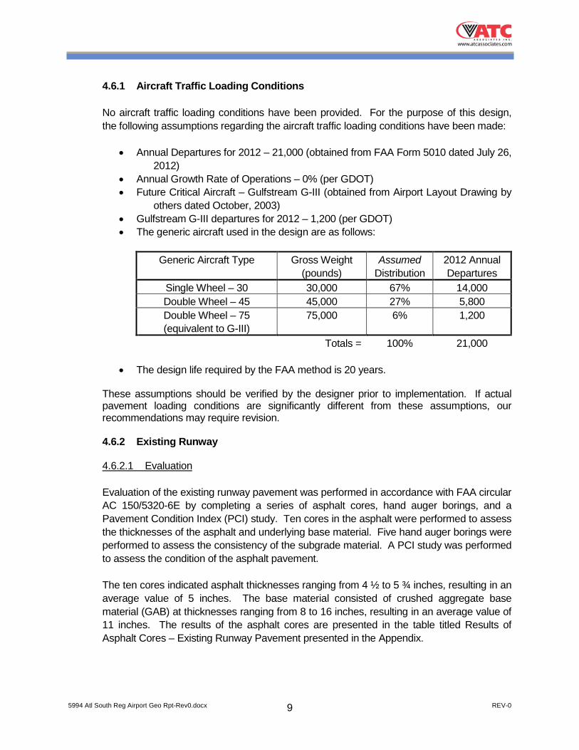
4.6.1 Aircraft Traffic Loading Conditions
No aircraft traffic loading conditions have been provided. For the purpose of this design, the following assumptions regarding the aircraft traffic loading conditions have been made:
• Annual Departures for 2012 – 21,000 (obtained from FAA Form 5010 dated July 26, 2012)
• Annual Growth Rate of Operations – 0% (per GDOT) • Future Critical Aircraft – Gulfstream G-III (obtained from Airport Layout Drawing by
others dated October, 2003) • Gulfstream G-III departures for 2012 – 1,200 (per GDOT) • The generic aircraft used in the design are as follows:
Generic Aircraft Type Gross Weight
(pounds) Assumed
Distribution 2012 Annual Departures
Single Wheel – 30 30,000 67% 14,000 Double Wheel – 45 45,000 27% 5,800 Double Wheel – 75 (equivalent to G-III)
75,000 6% 1,200
Totals = 100% 21,000
• The design life required by the FAA method is 20 years. These assumptions should be verified by the designer prior to implementation. If actual
pavement loading conditions are significantly different from these assumptions, our recommendations may require revision.
4.6.2 Existing Runway 4.6.2.1 Evaluation
Evaluation of the existing runway pavement was performed in accordance with FAA circular AC 150/5320-6E by completing a series of asphalt cores, hand auger borings, and a Pavement Condition Index (PCI) study. Ten cores in the asphalt were performed to assess the thicknesses of the asphalt and underlying base material. Five hand auger borings were performed to assess the consistency of the subgrade material. A PCI study was performed to assess the condition of the asphalt pavement. The ten cores indicated asphalt thicknesses ranging from 4 ½ to 5 ¾ inches, resulting in an average value of 5 inches. The base material consisted of crushed aggregate base material (GAB) at thicknesses ranging from 8 to 16 inches, resulting in an average value of 11 inches. The results of the asphalt cores are presented in the table titled Results of Asphalt Cores – Existing Runway Pavement presented in the Appendix.
5994 Atl South Reg Airport Geo Rpt-Rev0.docx REV-0 10
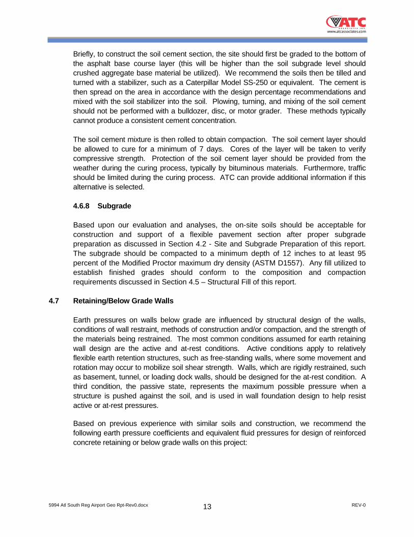
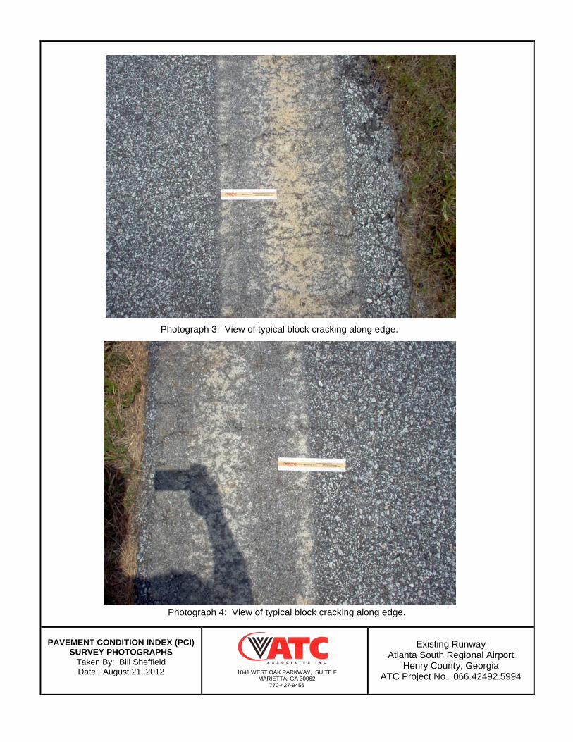
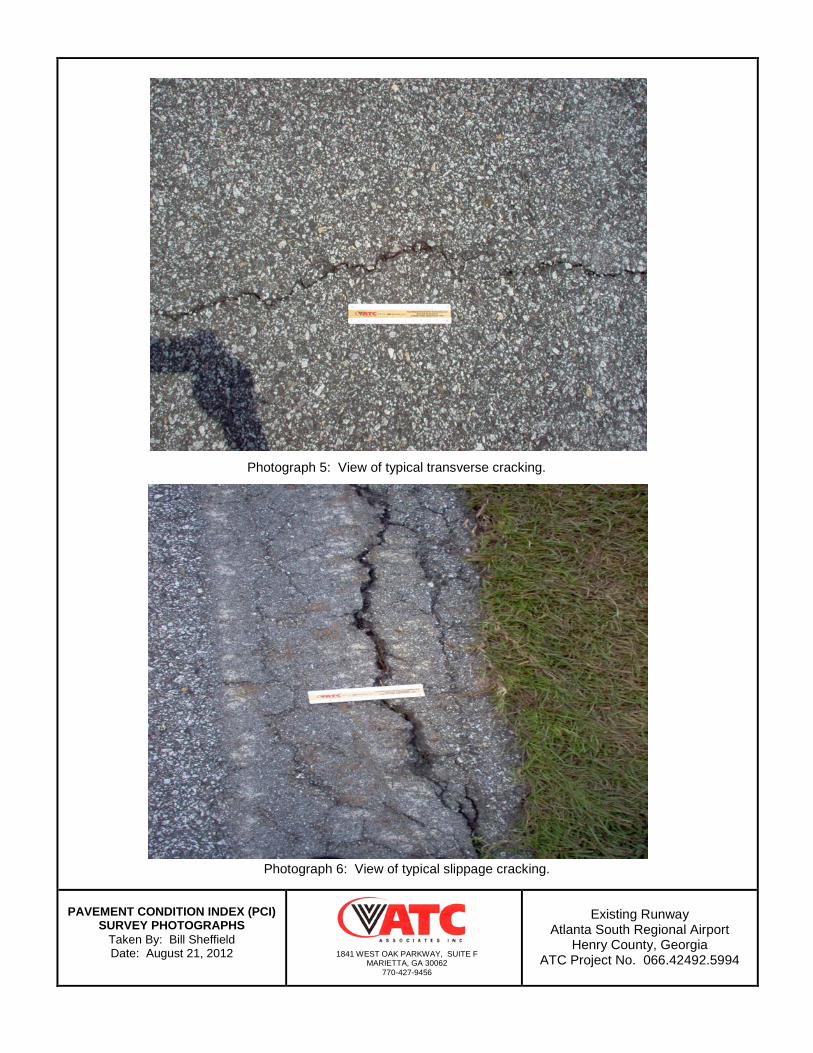
The five hand auger borings indicated the soil subgrade consisted primarily of silty fine sands (SM) and clayey fine sands (SC). Dynamic Cone Penetrometer values obtained below the GAB level indicated blow counts ranging from 6 to 20+ blows. Using geotechnical residual soil correlations, these values correspond to CBR values ranging from 4.3 to 5.3, with an average value of 5.0. Utilizing 85% of the CBR value (per the design procedure) results in a CBR value of 4.3 for the soil subgrade of the existing runway. The results of the hand auger borings are presented in the table titled Summary of Hand Auger Borings in the Appendix. The Pavement Condition Index (PCI) study was performed in accordance with ASTM D5340 Standard Test Method for Airport Pavement Condition Index Surveys. The PCI values of the selected sample units ranged from 70 to 80, resulting in an average value of 75. These values correspond to a rating of good. The results of the PCI study are presented in the table titled Summary of Pavement Condition Index (PCI) Survey – Existing Runway Pavement in the Appendix. Photographs of documenting the distress observed during the PCI Survey are also presented in the Appendix. The types of distress identified during the PCI study consisted primarily of moderate to low severity longitudinal cracking. Low severity block cracking was identified along the edges of the pavement in several of the sample units. A large section of low severity block cracking was also observed on the interior of the pavement in one of the sample units. Occasional low severity transverse cracking and slippage cracking were also observed. Grass was also observed growing in some of the longitudinal cracks.
4.6.2.2 Overlay Pavement Design
Our evaluation indicates that the existing runway pavement section is undersized for the assumed (anticipated) future aircraft traffic loading conditions and a design life of 20 years. In order to accommodate the future aircraft traffic, we recommend a 6 inch overlay of hot mix asphalt (FAA Designation P-401/P-403) be placed over the existing asphalt. Preparation of the existing asphalt pavement should be performed prior to placement of the overlay. Based upon the findings of the PCI study, we envision this consisting of cleaning the grass from the longitudinal cracks and then filling them with sealer. Transverse cracks should also be cleaned and filled. Since the block cracking is typically located within 5 feet of the pavement edge, it may be prudent to remove the existing surface layer within this area and replace during the widening and/or overlay operations. Existing paint must be removed or scarified. Other distress that may be present but not identified in the PCI study should also be repaired prior to placement of the overlay. The overlay operations should be coordinated with the widening operations discussed in the next section.
5994 Atl South Reg Airport Geo Rpt-Rev0.docx REV-0 11
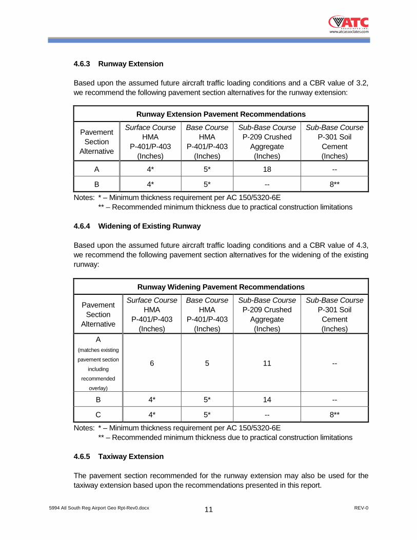
4.6.3 Runway Extension Based upon the assumed future aircraft traffic loading conditions and a CBR value of 3.2,
we recommend the following pavement section alternatives for the runway extension:
Runway Extension Pavement Recommendations
Pavement Section
Alternative
Surface Course HMA
P-401/P-403 (Inches)
Base Course HMA
P-401/P-403 (Inches)
Sub-Base Course P-209 Crushed
Aggregate (Inches)
Sub-Base Course P-301 Soil Cement (Inches)
A 4* 5* 18 --
B 4* 5* -- 8**
Notes: * – Minimum thickness requirement per AC 150/5320-6E ** – Recommended minimum thickness due to practical construction limitations 4.6.4 Widening of Existing Runway Based upon the assumed future aircraft traffic loading conditions and a CBR value of 4.3,
we recommend the following pavement section alternatives for the widening of the existing runway:
Runway Widening Pavement Recommendations
Pavement Section
Alternative
Surface Course HMA
P-401/P-403 (Inches)
Base Course HMA
P-401/P-403 (Inches)
Sub-Base Course P-209 Crushed
Aggregate (Inches)
Sub-Base Course P-301 Soil Cement (Inches)
A (matches existing
pavement section
including
recommended
overlay)
6 5 11 --
B 4* 5* 14 --
C 4* 5* -- 8**
Notes: * – Minimum thickness requirement per AC 150/5320-6E ** – Recommended minimum thickness due to practical construction limitations 4.6.5 Taxiway Extension
The pavement section recommended for the runway extension may also be used for the taxiway extension based upon the recommendations presented in this report.
5994 Atl South Reg Airport Geo Rpt-Rev0.docx REV-0 12
Evaluation of the existing taxiways and aprons was beyond the scope of this assessment. Utilizing an overlay similar to that recommended above for the existing runway appears reasonable. However, it would be prudent to verify the thickness of the existing taxiway and apron pavement sections in order to confirm the recommended overlay thickness.
4.6.6 Sub-Base Course Material The recommended pavement design alternatives are subject to successful completion of
site and subgrade preparation and fill placement as recommended in this report. The compaction, quality, and gradation of the crushed aggregate sub-base material (P-209) will directly affect the quality and life of the pavement section. Consequently, we recommend a minimum compaction of 100 percent of the maximum dry density for the P-209 material as determined by the Modified Proctor compaction test (ASTM D1557, Method D). An ATC soil engineering technician working under the direction of a geotechnical engineer should observe placement and compaction of the sub-base course material and perform density tests to confirm that the material has been placed in accordance with our recommendations. The sub-base materials should extend at least 2 feet horizontally beyond the planned pavement edges.
The crushed aggregate base material (P-209) in the sub-base should conform to
specifications from both Federal Aviation Administration and Georgia Department of Transportation.
4.6.7 Soil Cement Treated Sub-Base The tested subgrade soils in the runway extension area exhibit a CBR value of 3.2. This
results in a relatively thick pavement section for the runway extension. If the subgrade soils could be strengthened by utilizing soil cement, then this might prove beneficial to the project by replacing the crushed aggregate base material layer, and thus reducing construction costs. We recommend the economics of utilizing soil cement be evaluated. Recommendations for soil cement construction are presented below.
We recommend a minimum thickness of 8 inches be utilized for the soil cement layer due
to practical construction limitations. The soil cement should extend at least 2 feet horizontally beyond the planned pavement edges.
The design and construction of the soil cement treated sub-base should be performed in
accordance with FAA AC 150/5370-10F Standard for Specifying Construction of Airports. The percentage of cement necessary will vary based upon the soils composition, moisture
content, and behavior in the wet/dry or freeze/thaw testing cycles. An initial starting percentage of 7% by weight is typical. We recommend a laboratory testing program be performed in accordance with AC 150/5370-10F Section P-301, in order to establish the optimal cement percentage for the area if this alternative is selected.
5994 Atl South Reg Airport Geo Rpt-Rev0.docx REV-0 13
Briefly, to construct the soil cement section, the site should first be graded to the bottom of the asphalt base course layer (this will be higher than the soil subgrade level should crushed aggregate base material be utilized). We recommend the soils then be tilled and turned with a stabilizer, such as a Caterpillar Model SS-250 or equivalent. The cement is then spread on the area in accordance with the design percentage recommendations and mixed with the soil stabilizer into the soil. Plowing, turning, and mixing of the soil cement should not be performed with a bulldozer, disc, or motor grader. These methods typically cannot produce a consistent cement concentration.
The soil cement mixture is then rolled to obtain compaction. The soil cement layer should
be allowed to cure for a minimum of 7 days. Cores of the layer will be taken to verify compressive strength. Protection of the soil cement layer should be provided from the weather during the curing process, typically by bituminous materials. Furthermore, traffic should be limited during the curing process. ATC can provide additional information if this alternative is selected.
4.6.8 Subgrade Based upon our evaluation and analyses, the on-site soils should be acceptable for
construction and support of a flexible pavement section after proper subgrade preparation as discussed in Section 4.2 - Site and Subgrade Preparation of this report. The subgrade should be compacted to a minimum depth of 12 inches to at least 95 percent of the Modified Proctor maximum dry density (ASTM D1557). Any fill utilized to establish finished grades should conform to the composition and compaction requirements discussed in Section 4.5 – Structural Fill of this report.
4.7 Retaining/Below Grade Walls Earth pressures on walls below grade are influenced by structural design of the walls,
conditions of wall restraint, methods of construction and/or compaction, and the strength of the materials being restrained. The most common conditions assumed for earth retaining wall design are the active and at-rest conditions. Active conditions apply to relatively flexible earth retention structures, such as free-standing walls, where some movement and rotation may occur to mobilize soil shear strength. Walls, which are rigidly restrained, such as basement, tunnel, or loading dock walls, should be designed for the at-rest condition. A third condition, the passive state, represents the maximum possible pressure when a structure is pushed against the soil, and is used in wall foundation design to help resist active or at-rest pressures.
Based on previous experience with similar soils and construction, we recommend the
following earth pressure coefficients and equivalent fluid pressures for design of reinforced concrete retaining or below grade walls on this project:
5994 Atl South Reg Airport Geo Rpt-Rev0.docx REV-0 14
Earth Pressure Conditions Coefficient Recommended Equivalent Fluid Pressure (pcf)
Active (Ka) 0.36 45
At-Rest (Ko) 0.53 66
Passive (Kp) 2.77 173 A moist soil unit weight of 125 pounds per cubic foot (pcf) should be used for design
calculations. Our recommendations assume that the ground surface above the wall is level. A coefficient of friction value between soil and concrete of 0.35 is recommended.
The recommended equivalent fluid pressures assume that constantly functioning drainage
systems are installed between walls and soil backfill to prevent the accidental buildup of hydrostatic pressures and lateral stresses in excess of those stated.
Foundations for retaining walls may be sized for a maximum allowable net bearing
pressure of 3,000 pounds per square foot (psf). Tractors and other heavy equipment should not operate within 10 feet of below grade walls
to prevent lateral pressures in excess of those cited. If footings or other surcharge loadings are located a short distance outside below grade walls, they may also exert appreciable additional lateral pressures that must be considered.
These retaining wall/below grade wall recommendations should not be correlated with soil
parameters for use in Mechanically Stabilized Earth (MSE) wall design. We recommend that soil parameters for any MSE retaining wall design be established through appropriate laboratory testing by the wall designer.
5994 Atl South Reg Airport Geo Rpt-Rev0.docx REV-0 15
5.0 QUALIFICATIONS OF RECOMMENDATIONS
Our evaluation has been based on our understanding of the site and project information
and the data obtained during our field exploration. The general subsurface conditions used were based on interpolation of the subsurface data between the borings. Regardless of the thoroughness of a subsurface exploration, there is the possibility that conditions between borings will differ from those at the boring locations, that conditions are not as anticipated by the designers, or that the construction process has altered the soil conditions. Therefore, geotechnical engineers should evaluate earthwork and foundation construction to verify that the conditions anticipated in design actually exist. Otherwise, we assume no responsibility for construction compliance with the design concepts, specifications or recommendations.
The design recommendations in this report have been developed on the basis of the
previously described project characteristics and subsurface conditions. If project criteria, or locations change, we should be permitted to determine if the recommendations must be modified. The findings of such a review will be presented in a supplemental report.
The nature and extent of variations between the borings may not become evident until the
course of construction. If such variations then appear evident, it will be necessary to re-evaluate the recommendations of this report after on-site observations of the conditions.
Our professional services have been performed, our findings derived, and our
recommendations prepared in accordance with generally accepted geotechnical engineering principles and practices. This warranty is in lieu of all other warranties either expressed or implied.

APPENDIX

ATLANTA SOUTH REGIONAL AIRPORTRUNWAY AND TAXIWAY EXTENSION
7
6
7
7
874.7
864.9
1
2
3
4
3" TOPSOILRESIDUUM: Firm light brown purple micaceousfine sandy SILT (MH)
BORING TERMINATED
SS
SS
SS
SS
1
At Completion--
Depth to Groundwater
24RC
Sta
ndar
d P
enet
ratio
nTe
st, N
blo
ws/
foot
CU
60
Page
2010
PIEDMONT
No.
B- 1
TEST BORING RECORD
Sample Type
- Cuttings
8/21/12
HSA
40
- Atterberg Limits
HSA (AUTO HAMMER)
5Ele
vatio
n
Sam
pler
Gra
phic
s
Dep
thS
cale
- Driven Split Spoon
Gro
undw
ater
BORING #
Boring MethodSS
Sca
le
- Triaxial
Laboratory Testing
- Consolidation
100
- Mud DrillingUD - Shelby Tube- Rock Core
MC
SOIL CLASSIFICATION
After6.0
hours
STANDARD PENETRATION RESISTANCE(BLOWS PER FOOT)
Cave Depth
- Hollow Stem Augers
BORING METHOD
GSCAT
8/21/12DATE COMPLETED
PROJECT NAME
- Moisture Content- Grain Size NONE
ft.ft.ft.ft.
Noted on Drilling Rods
NONEMD
066.42492.5994
Sam
ple
Sam
ple
Type
(Lab
orat
ory
Test
ing)
DATE STARTED
DRILL FOREMAN
5
10
SURFACE ELEVATION 874.9
of1
PROJECT NUMBER
ATLANTA SOUTH REGIONAL AIRPORT RUNWAY
1841 West Oak Parkway, Ste FMarietta, GA 30062
770-427-9456Fax 770-427-1907
6
7
6
7
8
878.7
870.9
866.9
863.9
1
2
3
4
5
3" TOPSOILRESIDUUM: Firm light brown purple micaceousfine sandy SILT (MH)
Firm orange micaceous fine sandy SILT (ML)
Loose light brown gray micaceous silty fine SAND(SM)
BORING TERMINATED
SS
SS
SS
SS
SS
1
At Completion--
Depth to Groundwater
24RC
Sta
ndar
d P
enet
ratio
nTe
st, N
blo
ws/
foot
CU
60
Page
2010
PIEDMONT
No.
B- 2
TEST BORING RECORD
Sample Type
- Cuttings
8/21/12
HSA
40
- Atterberg Limits
HSA (AUTO HAMMER)
5Ele
vatio
n
Sam
pler
Gra
phic
s
Dep
thS
cale
- Driven Split Spoon
Gro
undw
ater
BORING #
Boring MethodSS
Sca
le
- Triaxial
Laboratory Testing
- Consolidation
100
- Mud DrillingUD - Shelby Tube- Rock Core
MC
SOIL CLASSIFICATION
After12.0
hours
STANDARD PENETRATION RESISTANCE(BLOWS PER FOOT)
Cave Depth
- Hollow Stem Augers
BORING METHOD
GSCAT
8/21/12DATE COMPLETED
PROJECT NAME
- Moisture Content- Grain Size NONE
ft.ft.ft.ft.
Noted on Drilling Rods
NONEMD
066.42492.5994
Sam
ple
Sam
ple
Type
(Lab
orat
ory
Test
ing)
DATE STARTED
DRILL FOREMAN
5
10
15
SURFACE ELEVATION 878.9
of1
PROJECT NUMBER
ATLANTA SOUTH REGIONAL AIRPORT RUNWAY
1841 West Oak Parkway, Ste FMarietta, GA 30062
770-427-9456Fax 770-427-1907

11
10
8
6
7
9
884.0
881.2
867.2
864.2
1
2
3
4
5
6
3" TOPSOILRESIDUUM: Medium dense red orange clayeyfine SAND (SC)
Firm to stiff red brown micaceous fine sandy SILT(MH)
Loose red white micaceous silty medium to fineSAND (SM)
BORING TERMINATED
SS
SS
SS
SS
SS
SS
1
At Completion--
Depth to Groundwater
24RC
Sta
ndar
d P
enet
ratio
nTe
st, N
blo
ws/
foot
CU
60
Page
2010
PIEDMONT
No.
B- 3
TEST BORING RECORD
Sample Type
- Cuttings
8/21/12
HSA
40
- Atterberg Limits
HSA (AUTO HAMMER)
5Ele
vatio
n
Sam
pler
Gra
phic
s
Dep
thS
cale
- Driven Split Spoon
Gro
undw
ater
BORING #
Boring MethodSS
Sca
le
- Triaxial
Laboratory Testing
- Consolidation
100
- Mud DrillingUD - Shelby Tube- Rock Core
MC
SOIL CLASSIFICATION
After17.0
hours
STANDARD PENETRATION RESISTANCE(BLOWS PER FOOT)
Cave Depth
- Hollow Stem Augers
BORING METHOD
GSCAT
8/21/12DATE COMPLETED
PROJECT NAME
- Moisture Content- Grain Size NONE
ft.ft.ft.ft.
Noted on Drilling Rods
NONEMD
066.42492.5994
Sam
ple
Sam
ple
Type
(Lab
orat
ory
Test
ing)
DATE STARTED
DRILL FOREMAN
5
10
15
20
SURFACE ELEVATION 884.2
of1
PROJECT NUMBER
ATLANTA SOUTH REGIONAL AIRPORT RUNWAY
1841 West Oak Parkway, Ste FMarietta, GA 30062
770-427-9456Fax 770-427-1907
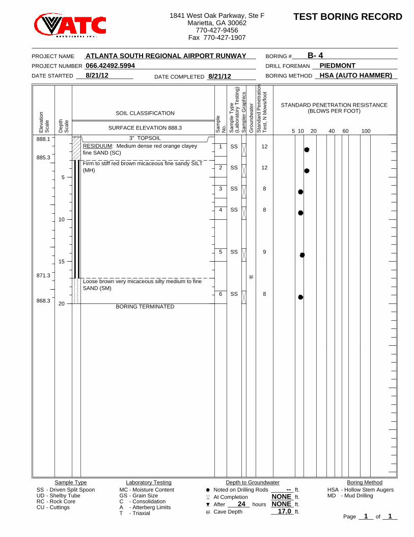
12
12
8
8
9
8
888.1
885.3
871.3
868.3
1
2
3
4
5
6
3" TOPSOILRESIDUUM: Medium dense red orange clayeyfine SAND (SC)
Firm to stiff red brown micaceous fine sandy SILT(MH)
Loose brown very micaceous silty medium to fineSAND (SM)
BORING TERMINATED
SS
SS
SS
SS
SS
SS
1
At Completion--
Depth to Groundwater
24RC
Sta
ndar
d P
enet
ratio
nTe
st, N
blo
ws/
foot
CU
60
Page
2010
PIEDMONT
No.
B- 4
TEST BORING RECORD
Sample Type
- Cuttings
8/21/12
HSA
40
- Atterberg Limits
HSA (AUTO HAMMER)
5Ele
vatio
n
Sam
pler
Gra
phic
s
Dep
thS
cale
- Driven Split Spoon
Gro
undw
ater
BORING #
Boring MethodSS
Sca
le
- Triaxial
Laboratory Testing
- Consolidation
100
- Mud DrillingUD - Shelby Tube- Rock Core
MC
SOIL CLASSIFICATION
After17.0
hours
STANDARD PENETRATION RESISTANCE(BLOWS PER FOOT)
Cave Depth
- Hollow Stem Augers
BORING METHOD
GSCAT
8/21/12DATE COMPLETED
PROJECT NAME
- Moisture Content- Grain Size NONE
ft.ft.ft.ft.
Noted on Drilling Rods
NONEMD
066.42492.5994
Sam
ple
Sam
ple
Type
(Lab
orat
ory
Test
ing)
DATE STARTED
DRILL FOREMAN
5
10
15
20
SURFACE ELEVATION 888.3
of1
PROJECT NUMBER
ATLANTA SOUTH REGIONAL AIRPORT RUNWAY
1841 West Oak Parkway, Ste FMarietta, GA 30062
770-427-9456Fax 770-427-1907
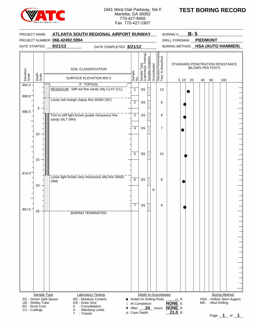
13
9
9
7
10
8
9
892.3
889.5
886.5
874.5
867.5
1
2
3
4
5
6
7
3" TOPSOILRESIDUUM: Stiff red fine sandy silty CLAY (CL)
Loose red orange clayey fine SAND (SC)
Firm to stiff light brown purple micaceous finesandy SILT (MH)
Loose light brown very micaceous silty fine SAND(SM)
BORING TERMINATED
SS
SS
SS
SS
SS
SS
SS
1
At Completion--
Depth to Groundwater
24RC
Sta
ndar
d P
enet
ratio
nTe
st, N
blo
ws/
foot
CU
60
Page
2010
PIEDMONT
No.
B- 5
TEST BORING RECORD
Sample Type
- Cuttings
8/21/12
HSA
40
- Atterberg Limits
HSA (AUTO HAMMER)
5Ele
vatio
n
Sam
pler
Gra
phic
s
Dep
thS
cale
- Driven Split Spoon
Gro
undw
ater
BORING #
Boring MethodSS
Sca
le
- Triaxial
Laboratory Testing
- Consolidation
100
- Mud DrillingUD - Shelby Tube- Rock Core
MC
SOIL CLASSIFICATION
After21.0
hours
STANDARD PENETRATION RESISTANCE(BLOWS PER FOOT)
Cave Depth
- Hollow Stem Augers
BORING METHOD
GSCAT
8/21/12DATE COMPLETED
PROJECT NAME
- Moisture Content- Grain Size NONE
ft.ft.ft.ft.
Noted on Drilling Rods
NONEMD
066.42492.5994
Sam
ple
Sam
ple
Type
(Lab
orat
ory
Test
ing)
DATE STARTED
DRILL FOREMAN
5
10
15
20
25
SURFACE ELEVATION 892.5
of1
PROJECT NUMBER
ATLANTA SOUTH REGIONAL AIRPORT RUNWAY
1841 West Oak Parkway, Ste FMarietta, GA 30062
770-427-9456Fax 770-427-1907
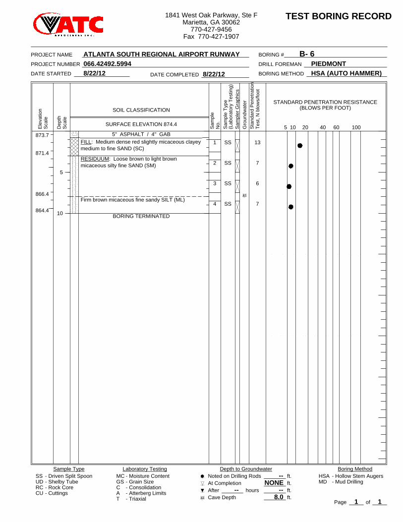
13
7
6
7
873.7
871.4
866.4
864.4
1
2
3
4
5" ASPHALT / 4" GABFILL: Medium dense red slightly micaceous clayeymedium to fine SAND (SC)
RESIDUUM: Loose brown to light brownmicaceous silty fine SAND (SM)
Firm brown micaceous fine sandy SILT (ML)
BORING TERMINATED
SS
SS
SS
SS
1
At Completion--
Depth to Groundwater
--RC
Sta
ndar
d P
enet
ratio
nTe
st, N
blo
ws/
foot
CU
60
Page
2010
PIEDMONT
No.
B- 6
TEST BORING RECORD
Sample Type
- Cuttings
8/22/12
HSA
40
- Atterberg Limits
HSA (AUTO HAMMER)
5Ele
vatio
n
Sam
pler
Gra
phic
s
Dep
thS
cale
- Driven Split Spoon
Gro
undw
ater
BORING #
Boring MethodSS
Sca
le
- Triaxial
Laboratory Testing
- Consolidation
100
- Mud DrillingUD - Shelby Tube- Rock Core
MC
SOIL CLASSIFICATION
After8.0
hours
STANDARD PENETRATION RESISTANCE(BLOWS PER FOOT)
Cave Depth
- Hollow Stem Augers
BORING METHOD
GSCAT
8/22/12DATE COMPLETED
PROJECT NAME
- Moisture Content- Grain Size NONE
ft.ft.ft.ft.
Noted on Drilling Rods
--MD
066.42492.5994
Sam
ple
Sam
ple
Type
(Lab
orat
ory
Test
ing)
DATE STARTED
DRILL FOREMAN
5
10
SURFACE ELEVATION 874.4
of1
PROJECT NUMBER
ATLANTA SOUTH REGIONAL AIRPORT RUNWAY
1841 West Oak Parkway, Ste FMarietta, GA 30062
770-427-9456Fax 770-427-1907
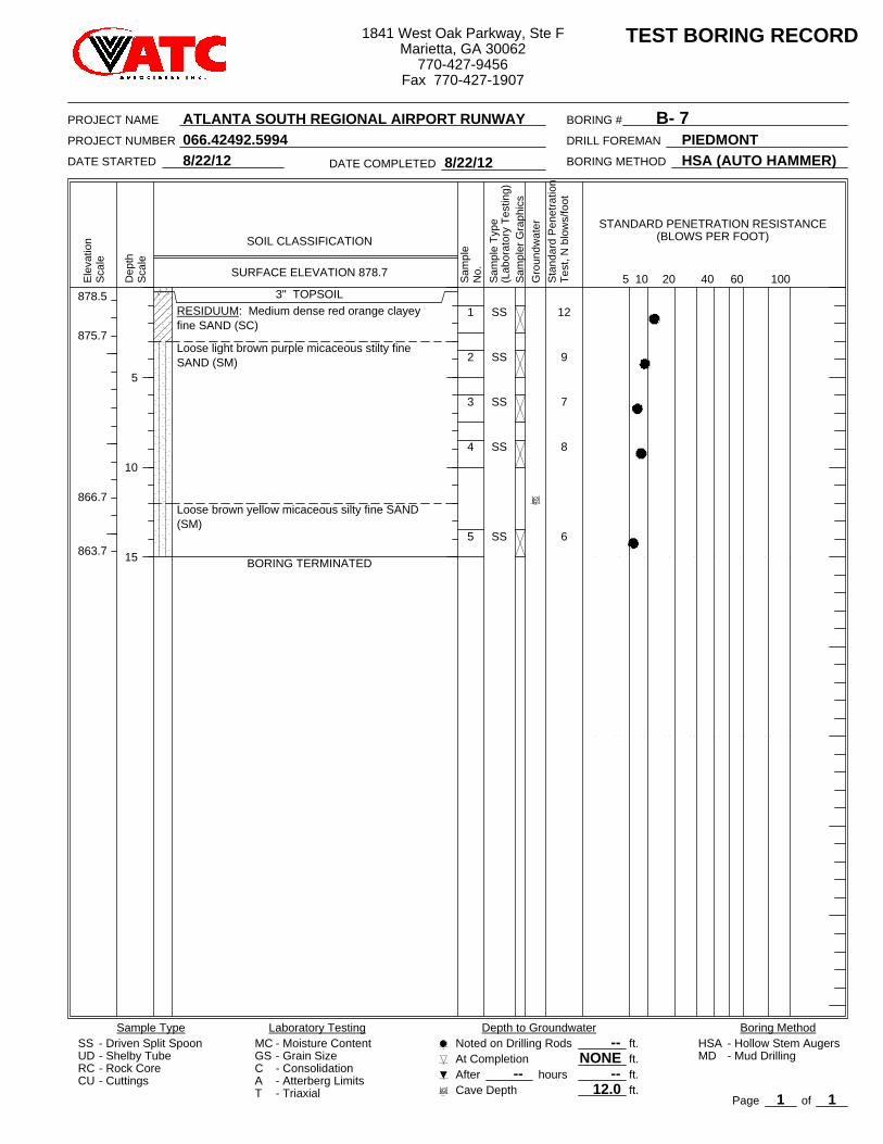
12
9
7
8
6
878.5
875.7
866.7
863.7
1
2
3
4
5
3" TOPSOILRESIDUUM: Medium dense red orange clayeyfine SAND (SC)
Loose light brown purple micaceous stilty fineSAND (SM)
Loose brown yellow micaceous silty fine SAND(SM)
BORING TERMINATED
SS
SS
SS
SS
SS
1
At Completion--
Depth to Groundwater
--RC
Sta
ndar
d P
enet
ratio
nTe
st, N
blo
ws/
foot
CU
60
Page
2010
PIEDMONT
No.
B- 7
TEST BORING RECORD
Sample Type
- Cuttings
8/22/12
HSA
40
- Atterberg Limits
HSA (AUTO HAMMER)
5Ele
vatio
n
Sam
pler
Gra
phic
s
Dep
thS
cale
- Driven Split Spoon
Gro
undw
ater
BORING #
Boring MethodSS
Sca
le
- Triaxial
Laboratory Testing
- Consolidation
100
- Mud DrillingUD - Shelby Tube- Rock Core
MC
SOIL CLASSIFICATION
After12.0
hours
STANDARD PENETRATION RESISTANCE(BLOWS PER FOOT)
Cave Depth
- Hollow Stem Augers
BORING METHOD
GSCAT
8/22/12DATE COMPLETED
PROJECT NAME
- Moisture Content- Grain Size NONE
ft.ft.ft.ft.
Noted on Drilling Rods
--MD
066.42492.5994
Sam
ple
Sam
ple
Type
(Lab
orat
ory
Test
ing)
DATE STARTED
DRILL FOREMAN
5
10
15
SURFACE ELEVATION 878.7
of1
PROJECT NUMBER
ATLANTA SOUTH REGIONAL AIRPORT RUNWAY
1841 West Oak Parkway, Ste FMarietta, GA 30062
770-427-9456Fax 770-427-1907
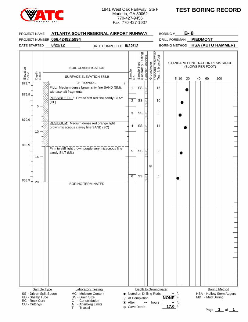
16
10
8
14
9
6
878.7
875.9
870.9
865.9
858.9
1
2
3
4
5
6
3" TOPSOILFILL: Medium dense brown silty fine SAND (SM),with asphalt fragments
POSSIBLE FILL: Firm to stiff red fine sandy CLAY(CL)
RESIDUUM: Medium dense red orange lightbrown micaceous clayey fine SAND (SC)
Firm to stiff light brown purple very micaceous finesandy SILT (ML)
BORING TERMINATED
SS
SS
SS
SS
SS
SS
1
At Completion--
Depth to Groundwater
--RC
Sta
ndar
d P
enet
ratio
nTe
st, N
blo
ws/
foot
CU
60
Page
2010
PIEDMONT
No.
B- 8
TEST BORING RECORD
Sample Type
- Cuttings
8/22/12
HSA
40
- Atterberg Limits
HSA (AUTO HAMMER)
5Ele
vatio
n
Sam
pler
Gra
phic
s
Dep
thS
cale
- Driven Split Spoon
Gro
undw
ater
BORING #
Boring MethodSS
Sca
le
- Triaxial
Laboratory Testing
- Consolidation
100
- Mud DrillingUD - Shelby Tube- Rock Core
MC
SOIL CLASSIFICATION
After17.0
hours
STANDARD PENETRATION RESISTANCE(BLOWS PER FOOT)
Cave Depth
- Hollow Stem Augers
BORING METHOD
GSCAT
8/22/12DATE COMPLETED
PROJECT NAME
- Moisture Content- Grain Size NONE
ft.ft.ft.ft.
Noted on Drilling Rods
--MD
066.42492.5994
Sam
ple
Sam
ple
Type
(Lab
orat
ory
Test
ing)
DATE STARTED
DRILL FOREMAN
5
10
15
20
SURFACE ELEVATION 878.9
of1
PROJECT NUMBER
ATLANTA SOUTH REGIONAL AIRPORT RUNWAY
1841 West Oak Parkway, Ste FMarietta, GA 30062
770-427-9456Fax 770-427-1907
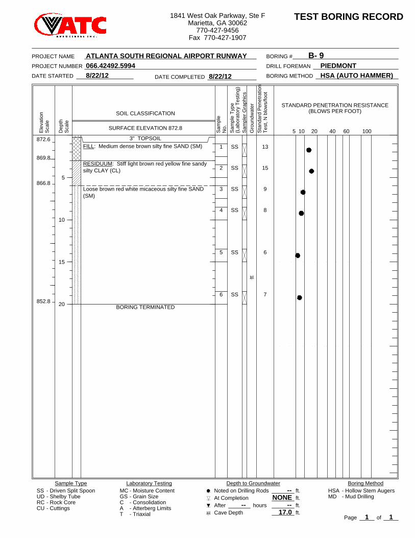
13
15
9
8
6
7
872.6
869.8
866.8
852.8
1
2
3
4
5
6
3" TOPSOILFILL: Medium dense brown silty fine SAND (SM)
RESIDUUM: Stiff light brown red yellow fine sandysilty CLAY (CL)
Loose brown red white micaceous silty fine SAND(SM)
BORING TERMINATED
SS
SS
SS
SS
SS
SS
1
At Completion--
Depth to Groundwater
--RC
Sta
ndar
d P
enet
ratio
nTe
st, N
blo
ws/
foot
CU
60
Page
2010
PIEDMONT
No.
B- 9
TEST BORING RECORD
Sample Type
- Cuttings
8/22/12
HSA
40
- Atterberg Limits
HSA (AUTO HAMMER)
5Ele
vatio
n
Sam
pler
Gra
phic
s
Dep
thS
cale
- Driven Split Spoon
Gro
undw
ater
BORING #
Boring MethodSS
Sca
le
- Triaxial
Laboratory Testing
- Consolidation
100
- Mud DrillingUD - Shelby Tube- Rock Core
MC
SOIL CLASSIFICATION
After17.0
hours
STANDARD PENETRATION RESISTANCE(BLOWS PER FOOT)
Cave Depth
- Hollow Stem Augers
BORING METHOD
GSCAT
8/22/12DATE COMPLETED
PROJECT NAME
- Moisture Content- Grain Size NONE
ft.ft.ft.ft.
Noted on Drilling Rods
--MD
066.42492.5994
Sam
ple
Sam
ple
Type
(Lab
orat
ory
Test
ing)
DATE STARTED
DRILL FOREMAN
5
10
15
20
SURFACE ELEVATION 872.8
of1
PROJECT NUMBER
ATLANTA SOUTH REGIONAL AIRPORT RUNWAY
1841 West Oak Parkway, Ste FMarietta, GA 30062
770-427-9456Fax 770-427-1907
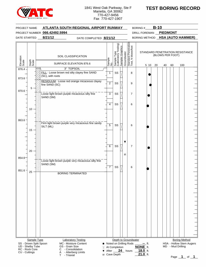
8
9
7
6
6
7
6
876.4
873.6
870.6
863.6
854.6
851.6
1
2
3
4
5
6
7
3" TOPSOILFILL: Loose brown red silty clayey fine SAND(SC), with roots
RESIDUUM: Loose red orange micaceous clayeyfine SAND (SC)
Loose light brown purple micaceous silty fineSAND (SM)
Firm light brown purple very micaceous fine sandySILT (ML)
Loose light brown purple very micaceous silty fineSAND (SM)
BORING TERMINATED
SS
SS
SS
SS
SS
SS
SS
1
At Completion--
Depth to Groundwater
24RC
Sta
ndar
d P
enet
ratio
nTe
st, N
blo
ws/
foot
CU
60
Page
2010
PIEDMONT
No.
B-10
TEST BORING RECORD
Sample Type
- Cuttings
8/21/12
HSA
40
- Atterberg Limits
HSA (AUTO HAMMER)
5Ele
vatio
n
Sam
pler
Gra
phic
s
Dep
thS
cale
- Driven Split Spoon
Gro
undw
ater
BORING #
Boring MethodSS
Sca
le
- Triaxial
Laboratory Testing
- Consolidation
100
- Mud DrillingUD - Shelby Tube- Rock Core
MC
SOIL CLASSIFICATION
After21.0
hours
STANDARD PENETRATION RESISTANCE(BLOWS PER FOOT)
Cave Depth
- Hollow Stem Augers
BORING METHOD
GSCAT
8/21/12DATE COMPLETED
PROJECT NAME
- Moisture Content- Grain Size NONE
ft.ft.ft.ft.
Noted on Drilling Rods
18.0MD
066.42492.5994
Sam
ple
Sam
ple
Type
(Lab
orat
ory
Test
ing)
DATE STARTED
DRILL FOREMAN
5
10
15
20
25
SURFACE ELEVATION 876.6
of1
PROJECT NUMBER
ATLANTA SOUTH REGIONAL AIRPORT RUNWAY
1841 West Oak Parkway, Ste FMarietta, GA 30062
770-427-9456Fax 770-427-1907
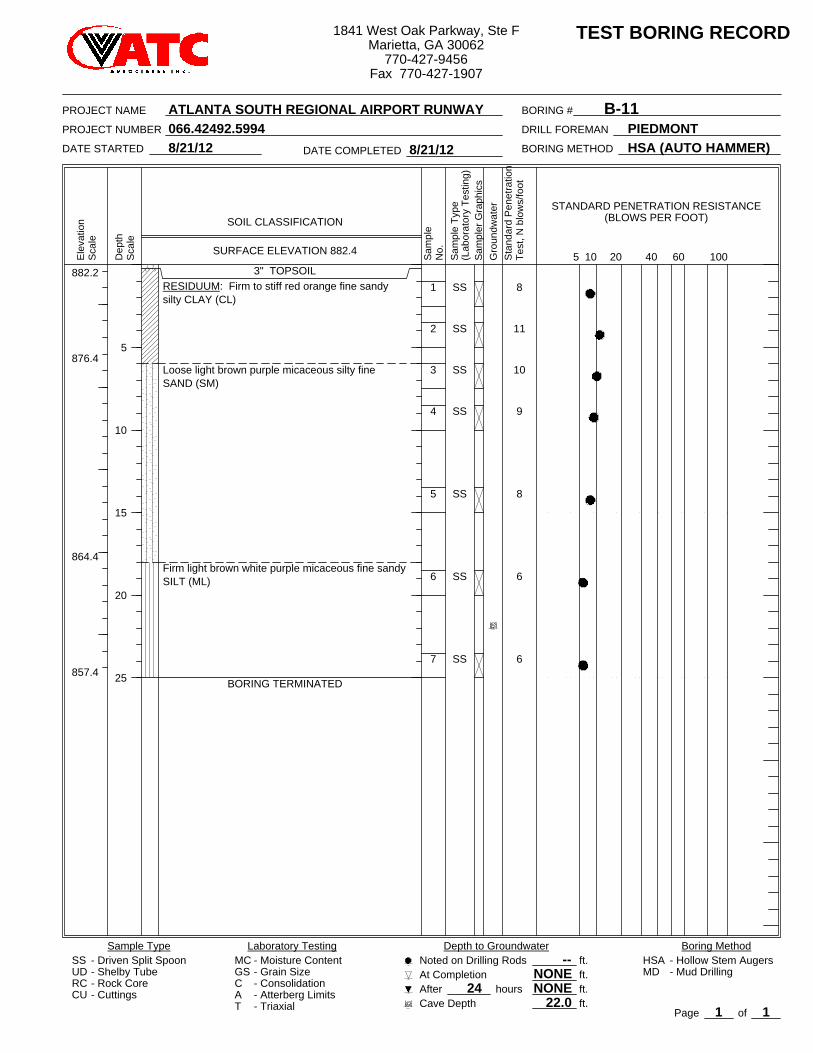
8
11
10
9
8
6
6
882.2
876.4
864.4
857.4
1
2
3
4
5
6
7
3" TOPSOILRESIDUUM: Firm to stiff red orange fine sandysilty CLAY (CL)
Loose light brown purple micaceous silty fineSAND (SM)
Firm light brown white purple micaceous fine sandySILT (ML)
BORING TERMINATED
SS
SS
SS
SS
SS
SS
SS
1
At Completion--
Depth to Groundwater
24RC
Sta
ndar
d P
enet
ratio
nTe
st, N
blo
ws/
foot
CU
60
Page
2010
PIEDMONT
No.
B-11
TEST BORING RECORD
Sample Type
- Cuttings
8/21/12
HSA
40
- Atterberg Limits
HSA (AUTO HAMMER)
5Ele
vatio
n
Sam
pler
Gra
phic
s
Dep
thS
cale
- Driven Split Spoon
Gro
undw
ater
BORING #
Boring MethodSS
Sca
le
- Triaxial
Laboratory Testing
- Consolidation
100
- Mud DrillingUD - Shelby Tube- Rock Core
MC
SOIL CLASSIFICATION
After22.0
hours
STANDARD PENETRATION RESISTANCE(BLOWS PER FOOT)
Cave Depth
- Hollow Stem Augers
BORING METHOD
GSCAT
8/21/12DATE COMPLETED
PROJECT NAME
- Moisture Content- Grain Size NONE
ft.ft.ft.ft.
Noted on Drilling Rods
NONEMD
066.42492.5994
Sam
ple
Sam
ple
Type
(Lab
orat
ory
Test
ing)
DATE STARTED
DRILL FOREMAN
5
10
15
20
25
SURFACE ELEVATION 882.4
of1
PROJECT NUMBER
ATLANTA SOUTH REGIONAL AIRPORT RUNWAY
1841 West Oak Parkway, Ste FMarietta, GA 30062
770-427-9456Fax 770-427-1907
5994 Atl South Reg Airport Cores.docx
RESULTS OF ASPHALT CORES – EXISTING RUNWAY PAVEMENT Atlanta South Regional Airport
Henry County, Georgia ATC Project Number 066.42492.5994
Core Number
Overlay1
HMA Thickness (Inches)
Surface Course2
HMA Thickness (Inches)
Base Course3
HMA Thickness (Inches)
Subbase GAB
Thickness (Inches)
Subgrade Material
C-1 1 ¾ 1 ¾ 1 ¼ 13 Soil C-2 2 1 ½ 1 ½ 11 Soil C-3 2 1 ¾ 1 ¾ 11 Soil C-4 2 ¼ 1 ½ 2 10 Soil C-5 2 1 ½ 1 9 Soil C-6 2 1 ¼ 1 ½ 10 Soil C-7 2 ¼ 1 ½ 2 16 Soil C-8 2 ½ 1 ½ 1 ½ 13 Soil C-9 2 1 ½ 1 ½ 8 Soil C-10 2 2 1 ½ 10 Soil
Averages = 2 1 ½ 1 ½ 11 Notes: 1 – Hot mixed asphalt (HMA) placed as overlay in June, 2001.
2 – HMA placed as surface course at the time of the original runway construction. 3 – HMA placed as base course at the time of the original runway construction.
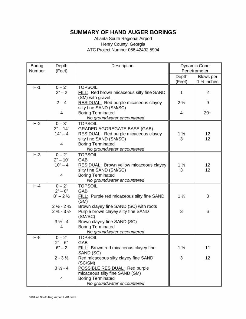
5994 Atl South Reg Airport HAB.docx
SUMMARY OF HAND AUGER BORINGS Atlanta South Regional Airport
Henry County, Georgia ATC Project Number 066.42492.5994
Boring Number
Depth (Feet)
Description Dynamic Cone Penetrometer
Depth (Feet)
Blows per 1 ¾ inches
H-1 0 – 2” 2” – 2
2 – 4
4
TOPSOIL FILL: Red brown micaceous silty fine SAND (SM) with gravel RESIDUAL: Red purple micaceous clayey silty fine SAND (SM/SC) Boring Terminated
No groundwater encountered
1
2 ½ 4
2
9
20+
H-2 0 – 3” 3” – 14” 14” – 4
4
TOPSOIL GRADED AGGREGATE BASE (GAB) RESIDUAL: Red purple micaceous clayey silty fine SAND (SM/SC) Boring Terminated
No groundwater encountered
1 ½ 3
12 12
H-3 0 – 2” 2” – 10” 10” – 4
4
TOPSOIL GAB RESIDUAL: Brown yellow micaceous clayey silty fine SAND (SM/SC) Boring Terminated
No groundwater encountered
1 ½ 3
12 12
H-4 0 – 2” 2” – 8”
8” – 2 ½
2 ½ - 2 ¾ 2 ¾ - 3 ½
3 ½ - 4
4
TOPSOIL GAB FILL: Purple red micaceous silty fine SAND (SM) Brown clayey fine SAND (SC) with roots Purple brown clayey silty fine SAND (SM/SC) Brown clayey fine SAND (SC) Boring Terminated
No groundwater encountered
1 ½ 3
3
6
H-5 0 – 2” 2” – 6” 6” – 2
2 - 3 ½
3 ½ - 4
4
TOPSOIL GAB FILL: Brown red micaceous clayey fine SAND (SC) Red micaceous silty clayey fine SAND (SC/SM) POSSIBLE RESIDUAL: Red purple micaceous silty fine SAND (SM) Boring Terminated
No groundwater encountered
1 ½ 3
11
12
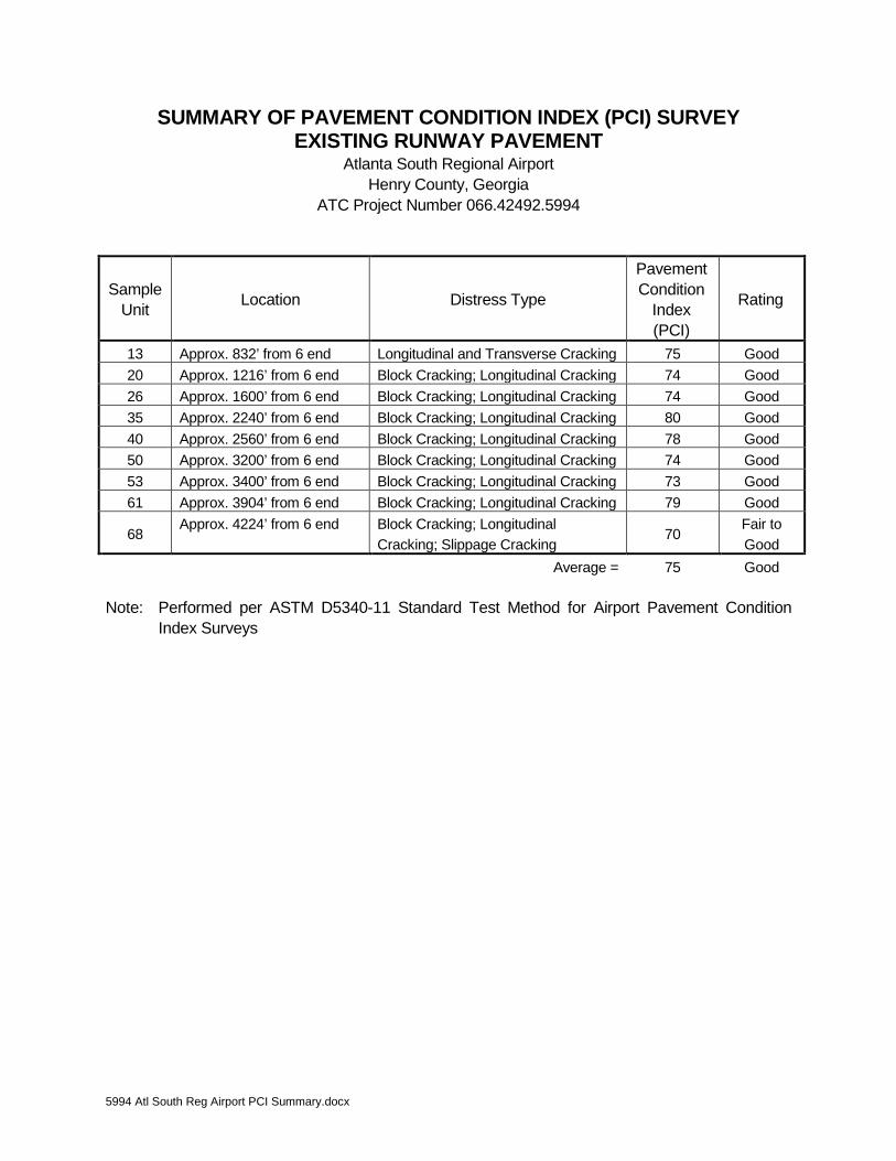
5994 Atl South Reg Airport PCI Summary.docx
SUMMARY OF PAVEMENT CONDITION INDEX (PCI) SURVEY EXISTING RUNWAY PAVEMENT
Atlanta South Regional Airport Henry County, Georgia
ATC Project Number 066.42492.5994
Sample Unit Location Distress Type
Pavement Condition
Index (PCI)
Rating
13 Approx. 832’ from 6 end Longitudinal and Transverse Cracking 75 Good 20 Approx. 1216’ from 6 end Block Cracking; Longitudinal Cracking 74 Good 26 Approx. 1600’ from 6 end Block Cracking; Longitudinal Cracking 74 Good 35 Approx. 2240’ from 6 end Block Cracking; Longitudinal Cracking 80 Good 40 Approx. 2560’ from 6 end Block Cracking; Longitudinal Cracking 78 Good 50 Approx. 3200’ from 6 end Block Cracking; Longitudinal Cracking 74 Good 53 Approx. 3400’ from 6 end Block Cracking; Longitudinal Cracking 73 Good 61 Approx. 3904’ from 6 end Block Cracking; Longitudinal Cracking 79 Good
68 Approx. 4224’ from 6 end Block Cracking; Longitudinal
Cracking; Slippage Cracking 70
Fair to Good
Average = 75 Good Note: Performed per ASTM D5340-11 Standard Test Method for Airport Pavement Condition
Index Surveys
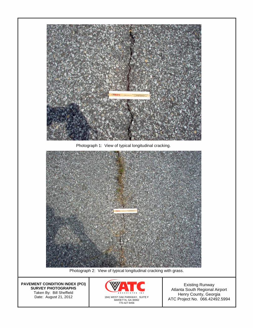
PAVEMENT CONDITION INDEX (PCI)
SURVEY PHOTOGRAPHS Taken By: Bill Sheffield Date: August 21, 2012
Existing Runway
Atlanta South Regional Airport Henry County, Georgia
ATC Project No. 066.42492.5994
1841 WEST OAK PARKWAY, SUITE F MARIETTA, GA 30062
770-427-9456
Photograph 1: View of typical longitudinal cracking.
Photograph 2: View of typical longitudinal cracking with grass.
PAVEMENT CONDITION INDEX (PCI)
SURVEY PHOTOGRAPHS Taken By: Bill Sheffield Date: August 21, 2012
Existing Runway
Atlanta South Regional Airport Henry County, Georgia
ATC Project No. 066.42492.5994
1841 WEST OAK PARKWAY, SUITE F MARIETTA, GA 30062
770-427-9456
Photograph 3: View of typical block cracking along edge.
Photograph 4: View of typical block cracking along edge.
PAVEMENT CONDITION INDEX (PCI)
SURVEY PHOTOGRAPHS Taken By: Bill Sheffield Date: August 21, 2012
Existing Runway
Atlanta South Regional Airport Henry County, Georgia
ATC Project No. 066.42492.5994
1841 WEST OAK PARKWAY, SUITE F MARIETTA, GA 30062
770-427-9456
Photograph 5: View of typical transverse cracking.
Photograph 6: View of typical slippage cracking.
BEARING RATIO TEST REPORTASTM D 1883-07
BEARING RATIO TEST REPORT
ATC ASSOCIATES INC.
Project No: 066.42492.5994
Project: Atlanta South Regional Airport
Location: B-1 to B-5 @ 0-10'
Sample Number: B-1 to B-5 @ 0-10'
Date:
Orange brown sandy elastic SILT
Test Description/Remarks:
Figure
113.3 13.4
Material DescriptionUSCS
Max.Dens.(pcf)
OptimumMoisture
(%)LL PI
Molded
Density(pcf)
Percent ofMax. Dens.
Moisture(%)
Soaked
Density(pcf)
Percent ofMax. Dens.
Moisture(%)
CBR (%)
0.10 in. 0.20 in.
LinearityCorrection
(in.)
Surcharge(lbs.)
Max.Swell(%)
1 103.6 91.4 13.3 101.8 89.9 28.2 2.3 3.1 0.003 25 1.7
2 112.2 99 13.4 109.3 96.4 26.1 2.9 4.0 0.004 25 2.7
3 114.8 101.3 13.2 111.8 98.7 24.2 3.2 5.0 0.012 25 2.7
Pen
etr
ati
on
Resis
tan
ce (
psi)
0
40
80
120
160
200
Penetration Depth (in.)0 0.1 0.2 0.3 0.4 0.5
Sw
ell
(%
)
0
1
2
3
4
5
Elapsed Time (hrs)0 24 48 72 96
CB
R (
%)
2
3
4
5
6
Molded Density (pcf)100 104 108 112 116 120
25 blows
56 blows
75 blows
CBR at 95% Max. Density = 3.2%for 0.20 in. Penetration
B-1 to B-5 @0-10'
9/15/12
Orange brown sandy elastic SILT
B-1 to B-5 @ 27.3 113.3 13.4 %
No. LOCATION AND DESCRIPTION REMARKS
Location: B-1 to B-5 @ 0-10' Sample Number: B-1 to B-5 @ 0-10'
No. USCS LL PI NAT. MOIST. OVERSIZE %< No.200 MAX. DRY DEN. OPT. MOIST.
FigureATC ASSOCIATES INC.
Dry
de
nsi
ty, p
cf
90
95
100
105
110
115
120
125
Water content, %
5 10 15 20 25 30
100% SATURATION CURVESFOR SPEC. GRAV. EQUAL TO:
2.82.72.6
PROCTOR TEST REPORT
PROJECT: Atlanta South Regional Airport
PROJECT NO.: 066.42492.5994
DATE: 9/18/2012
Test specification: ASTM D 1557-07 Method A Modified
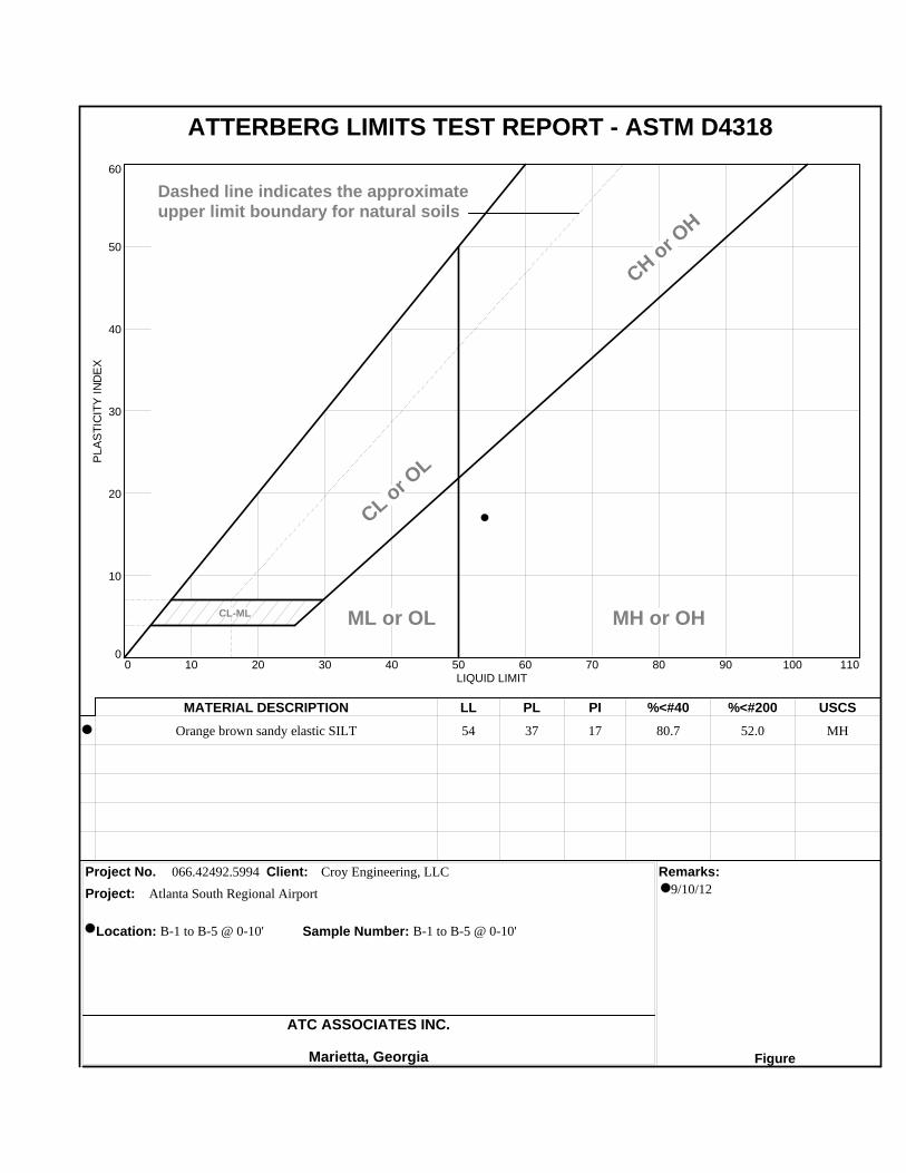
Orange brown sandy elastic SILT 54 37 17 80.7 52.0 MH
066.42492.5994 Croy Engineering, LLC
MATERIAL DESCRIPTION LL PL PI %<#40 %<#200 USCS
Project No. Client: Remarks:
Project:
ATC ASSOCIATES INC.
Marietta, Georgia Figure
Location: B-1 to B-5 @ 0-10' Sample Number: B-1 to B-5 @ 0-10'
PL
AS
TIC
ITY
IN
DE
X
0
10
20
30
40
50
60
LIQUID LIMIT0 10 20 30 40 50 60 70 80 90 100 110
CL-ML
CL or O
L
CH or O
H
ML or OL MH or OH
Dashed line indicates the approximateupper limit boundary for natural soils
4
7
ATTERBERG LIMITS TEST REPORT - ASTM D4318
9/10/12Atlanta South Regional Airport
Project No. Client: Remarks:
Project:
Location: B-1 to B-5 @ 0-10' Sample Number: B-1 to B-5 @ 0-10'
ATC ASSOCIATES INC.
Marietta, Georgia Figure
LL PL D85 D60 D50 D30 D15 D10 Cc Cu
MATERIAL DESCRIPTION TEST DATE USCS NM
54 37 0.5252 0.1388
Orange brown sandy elastic SILT MH 27.3
066.42492.5994 Croy Engineering, LLC
PE
RC
EN
T F
INE
R
0
10
20
30
40
50
60
70
80
90
100
PE
RC
EN
T C
OA
RS
ER
100
90
80
70
60
50
40
30
20
10
0
GRAIN SIZE - mm.
0.0010.010.1110100
% +3"Coarse
% Gravel
Fine Coarse Medium
% Sand
Fine Silt
% Fines
Clay
0.0 0.0 0.0 0.5 18.8 28.7 52.0
6 in
.
3 in
.
2 in
.
1½
in.
1 in
.
¾ in
.
½ in
.
3/8
in.
#4
#1
0
#2
0
#3
0
#4
0
#6
0
#1
00
#1
40
#2
00
Particle Size Distribution Report - ASTM D422
Atlanta South Regional Airport
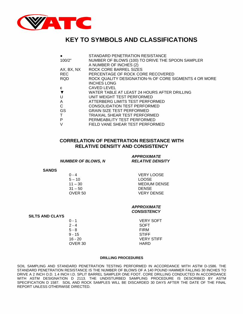
KEY TO SYMBOLS AND CLASSIFICATIONS
● STANDARD PENETRATION RESISTANCE 100/2” NUMBER OF BLOWS (100) TO DRIVE THE SPOON SAMPLER
A NUMBER OF INCHES (2) AX, BX, NX ROCK CORE BARREL SIZES REC PERCENTAGE OF ROCK CORE RECOVERED RQD ROCK QUALITY DESIGNATION-% OF CORE SIGMENTS 4 OR MORE
INCHES LONG є CAVED LEVEL ▼ WATER TABLE AT LEAST 24 HOURS AFTER DRILLING U UNIT WEIGHT TEST PERFORMED A ATTERBERG LIMITS TEST PERFORMED C CONSOLIDATION TEST PERFORMED GS GRAIN SIZE TEST PERFORMED T TRIAXIAL SHEAR TEST PERFORMED P PERMEABILITY TEST PERFORMED V FIELD VANE SHEAR TEST PERFORMED
CORRELATION OF PENETRATION RESISTANCE WITH RELATIVE DENSITY AND CONSISTENCY
APPROXIMATE
NUMBER OF BLOWS, N RELATIVE DENSITY SANDS
0 - 4 VERY LOOSE 5 – 10 LOOSE
11 – 30 MEDIUM DENSE 31 – 50 DENSE OVER 50 VERY DENSE APPROXIMATE CONSISTENCY
SILTS AND CLAYS 0 - 1 VERY SOFT 2 - 4 SOFT 5 - 8 FIRM
9 - 15 STIFF 16 - 20 VERY STIFF OVER 30 HARD
DRILLING PROCEDURES
SOIL SAMPLING AND STANDARD PENETRATION TESTING PERFORMED IN ACCORDANCE WITH ASTM D-1586. THE STANDARD PENETRATION RESISTANCE IS THE NUMBER OF BLOWS OF A 140 POUND HAMMER FALLING 30 INCHES TO DRIVE A 2 INCH O.D. 1.4 INCH I.D. SPLIT BARREL SAMPLER ONE FOOT. CORE DRILLING CONDUCTED IN ACCORDANCE WITH ASTM DESIGNATION D 2113. THE UNDISTURBED SAMPLING PROCEDURE IS DESCRIBED BY ASTM SPECIFICATION D 1587. SOIL AND ROCK SAMPLES WILL BE DISCARDED 30 DAYS AFTER THE DATE OF THE FINAL REPORT UNLESS OTHERWISE DIRECTED.