Embed Size (px)
Citation preview
Evaluation of In-Pavement Runway Guard Lights James W. Patterson, Jr. December 2004 DOT/FAA/AR-TN04/49 This document is available to the public through the National Technical Information Service (NTIS), Springfield, Virginia 22161.
U.S. Department of Transportation Federal Aviation Administration
ote
tech
nica
l not
e te
chni
caot
e te
chni
cal n
ote
tech
nica
NOTICE
This document is disseminated under the sponsorship of the U.S. Department of Transportation in the interest of information exchange. The United States Government assumes no liability for the contents or use thereof. The United States Government does not endorse products or manufacturers. Trade or manufacturer's names appear herein solely because they are considered essential to the objective of this report. This document does not constitute FAA certification policy. Consult your local FAA airports office as to its use. This report is available at the Federal Aviation Administration William J. Hughes Technical Center’s Full-Text Technical Reports page: actlibrary.tc.faa.gov in Adobe Acrobat portable document format (PDF).
Technical Report Documentation Page 1. Report No.
DOT/FAA/AR-TN04/49
2. Government Accession No. 3. Recipient's Catalog No.
4. Title and Subtitle
EVALUATION OF IN-PAVEMENT RUNWAY GUARD LIGHTS
5. Report Date
December 2004 6. Performing Organization Code
ATO-P R&D 7. Author(s) James W. Patterson, Jr.
8. Performing Organization Report No.
9. Performing Organization Name and Address
Federal Aviation Administration William J. Hughes Technical Center Airport Technology
10. Work Unit No. (TRAIS)
Research and Development Branch Atlantic City International Airport, NJ 08405
11. Contract or Grant No.
12. Sponsoring Agency Name and Address
U.S. Department of Transportation Federal Aviation Administration
13. Type of Report and Period Covered
Technical Note
Office of Aviation Research Washington, DC 20591
14. Sponsoring Agency Code
AAS-100 15. Supplementary Notes
Tom Paprocki of Hi-Tec Systems Inc. provided technical support throughout the course of this evaluation. 16. Abstract
In-pavement Runway Guard Lights are a series of alternate-flashing yellow, unidirectional in-pavement lighting fixtures (L-852G) equally spaced along a runway holding position marking that are only visible to aircraft approaching the hold position from the taxiway side of the fixture. In some instances, however, problems have been encountered where pilots have reported the lights visible from the opposite side of the fixtures, i.e., to aircraft exiting the runway. This situation produced false information to the pilots that resulted in operational problems. The purpose of this effort was to determine the extent, cause, and solution for specific operational problems resulting from these runway guard lights installed at hold lines at the Chicago O’Hare International Airport.
Solutions considered include modifications to the surrounding pavement, installation modifications, raising of the fixtures, installation of baffles, intensity adjustments, and the flash pattern of the system. Items investigated include lighting fixture design, lighting fixture photometrics, installation technique and workmanship, and system flash pattern. Two information gathering trips were conducted at Chicago O’Hare International Airport. In addition, preliminary photometric testing of various manufacturers’ runway guard light fixtures were conducted at the Federal Aviation Administration’s William J. Hughes Technical Center. In many cases, the manufacturers were contacted or visited to discuss potential changes that could be made to modify the fixtures.
It was determined that the L-852G in pavement runway guard light fixture, in its current design, will generate light that illuminates the pavement or the front lip in front of the fixture and that this light will be visible from the opposite side of the fixture. No modifications to either the pavement or fixture could be made that would eliminate this problem without sacrificing the intended photometric values of the fixture. The final solution to the problem at Chicago O’Hare was to reconfigure the system flash pattern so that it flashes in unison, thus eliminating the confusing random yellow flashing pattern that was viewed from the rear of the fixture. This simultaneous flash pattern maintains the intended integrity and design of the system when viewed from the taxiway side of the fixture.
17. Key Words
Runway guard lights, RGL; L-852G, Chicago O’Hare International Airport, ORD; In-pavement, Lighting problem
18. Distribution Statement
This document is available to the public through the National Technical Information Service (NTIS), Springfield, Virginia 22161.
19. Security Classif. (of this report)
Unclassified
20. Security Classif. (of this page)
Unclassified
21. No. of Pages
15
22. Price
Form DOT F1700.7 (8-72) Reproduction of completed page authorized
TABLE OF CONTENTS
Page EXECUTIVE SUMMARY v INTRODUCTION 1
Purpose 1 Objective 1 Related Documents 1 Background 1
DISCUSSION 4
Fixture Design 5 Fixture Installation 5 Flash Configuration 6 Federal Aviation Administration William J. Hughes Technical Center Testing 6 Considered Solutions 7
EVALUATION 8
TEST RESULTS 8
CONCLUSIONS 9
LIST OF FIGURES
Figure Page 1 Diagram of Chicago O’Hare International Airport 2 2 View of RGL Bar From Runway Side 3 3 Chamfer Painted Black in an Effort to Absorb and Reflect the Light Upward 4 4 An RGL Fixture With Light Reflecting Off the Edge of the Concrete 5 5 An RGL Fixture With Light Reflecting Off the Surface Pavement 6
iii/iv

EXECUTIVE SUMMARY
The effort described in this technical note was accomplished in response to a request for airport research and development from the Office of Airport Safety and Standards, AAS-1. In-pavement Runway Guard Lights are a series of alternate-flashing yellow, unidirectional lighting fixture type (L-852G) equally spaced along a runway hold position marking that are only visible to aircraft approaching the hold position from the taxiway side of the fixture. In some instances, however, problems have been encountered where pilots have reported the lights visible from the opposite side of the fixtures, i.e., to aircraft exiting the runway. This situation provided false information to pilots that resulted in operational problems. The purpose of this effort was to determine the extent and cause for specific operational problems resulting from these runway guard lights that are installed on hold lines at the Chicago O’Hare International Airport; specifically, pilots exiting from the runways reported seeing a considerable amount of light from these in-pavement fixtures, so much so that they believed that they might be entering a construction area. The objective of the research was to evaluate the cause and find solutions that would eliminate these problems. Solutions that were considered include modifications to the surrounding pavement, installation modifications, raising of the fixtures, installation of baffles, intensity adjustments, and the flash pattern of the system. Specific items that were investigated included lighting fixture design, lighting fixture photometrics, installation technique and workmanship, and system flash pattern. To investigate these issues, two information gathering trips were conducted at Chicago O’Hare International Airport. In addition, preliminary photometric testing of various manufacturers’ runway guard light fixtures were conducted at the Federal Aviation Administration William J. Hughes Technical Center. The manufacturers were contacted or visited to discuss potential changes that could be made to modify the fixtures. It was determined that the type L-852G runway guard light fixture, in its current design, will generate light that illuminates the pavement or the front lip in front of the fixture and that this light will be visible from the other side of the fixture. No modifications to either the pavement or fixture could be made that would eliminate this problem without sacrificing the intended photometric values of the fixture. The final solution to the problem at Chicago O’Hare was to reconfigure the system flash pattern so that it flashes in unison, thus eliminating the confusing random yellow flashing pattern that was viewed from the rear of the fixture. This simultaneous flash pattern maintains the intended integrity and design of the system when viewed from the taxiway side of the fixture.
v/vi

INTRODUCTION
PURPOSE.
The purpose of this investigative effort was to determine the extent and cause of operational problems resulting from the installation of in-pavement runway guard lights (RGL) at entrances to runways at Chicago O’Hare International Airport (ORD). Specifically, pilots exiting from the runways where the flashing yellow RGLs were located reported seeing considerable amounts of reflected light coming from the recessed fixtures, to the extent that several pilots halted short of exiting the runway and informed air traffic control (ATC) that they were concerned about possibly entering a construction area. As a result of this lighting problem, a major airline carrier lodged a formal complaint about the visible light being reflected in the runway direction, forcing the airport authorities to temporarily suspend operation of the in-pavement RGL. OBJECTIVE.
The objective of this effort was to research and evaluate the most effective and economical method to eliminate or redirect the reflected light associated with the in-pavement RGL systems installed at ORD. RELATED DOCUMENTS.
The following Federal Aviation Administration (FAA) advisory circulars (AC) pertain to RGL systems and equipment. • AC 150/5340-30, Design and Installation Details for Airport Visual Aids • AC 150/5345-46B, Specification for Runway and Taxiway Light Fixtures BACKGROUND.
In 1999, ORD installed over 30 sets of in-pavement RGLs at various key locations around the airport surface (see figure 1). Each RGL system consists of a series of type L-852G 105-watt traffic yellow, in-pavement, unidirectional airport lighting fixtures. The fixtures were installed per the FAA AC 150/5345-28, Low-Visibility Taxiway Systems, in an effort to increase operational safety at the airport and reduce the possibility of runway incursions. The installation of the fixtures was completed in late 1999. Upon ORD’s activation of the in-pavement RGL system, pilots began reporting that the flashing yellow lights created a confusing situation. The pilots saw the RGL lights from the runway side and interpreted the yellow flashing lights to be those of flashing barricade lights (see figure 2). The pilot, believing that the taxiway was closed due to the yellow construction barricade lights, proceeded to the next taxiway and found the same situation. The pilot contacted ATC who assured the pilot that there were no barricades in that area, and it was safe to proceed. Several other pilots encountered the same situation, refusing to exit the runway under the assumption that there were barricades in the way. This problem delayed arrivals and departures and forced other aircraft to go around.
1

Area of Evaluation
FIGURE 1. DIAGRAM OF CHICAGO O’HARE INTERNATIONAL AIRPORT
2

FIGURE 2. VIEW OF RGL BAR FROM RUNWAY SIDE
Through discussions with the pilots, it was learned that the cause of the pilot’s confusion came from viewing the in-pavement RGL from the runway side, which gave the same appearance as random flashing yellow barricade lights that are typically used to identify nonaccessible construction areas. When viewed from the runway side, the flashing pattern of the in-pavement RGLs appeared to be random rather than the alternating pattern that is visible from the front of the in-pavement RGL, thus creating a false signal to the rear of the fixtures. On April 5, 2000, engineers from FAA Headquarters (HQ) and the Great Lakes Regional Office went to ORD to investigate the RGL problem. Experimentation by the engineers showed that when the in-pavement lights were set to step 2 of a 5-step regulator, the lights provided acceptable intensity when viewed at night from the front of the fixture while reflecting very little light toward the runway. Further experimentation to simulate rain conditions with standing water forming on the fixtures revealed that when the fixtures where submerged in water, the reflected light toward the runway was zero. FAA HQ engineers were confident that the solution of reducing the step level of the RGL fixtures solved the problem, and offered ORD their proposed solution. ORD personnel, including airline representatives at ORD, were brought in to view the proposed solution of reducing the intensity level of the fixtures. The airline representatives rejected the solution, arguing that the reduction in the intensity of the fixtures would result in fixtures that do not meet the specifications, and the intensity would be too low for daytime use, especially in low-visibility conditions. It was also stated that they would not support using lower wattage lamps as a solution. While it may help to solve the problem, it would severely reduce the intended effectiveness of the fixtures. Being unable to resolve the reflective lighting problem, the Director of Airport Safety and Standards, AAS-1, requested the assistance of the Airport Technology R&D Branch, Airport Safety Section, AAR-411. While trying not to physically raise the fixtures so that minimal light
3
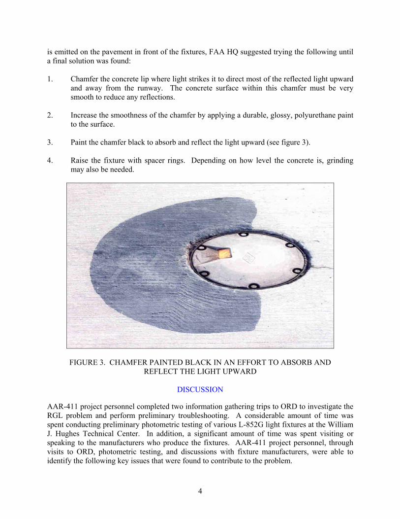
is emitted on the pavement in front of the fixtures, FAA HQ suggested trying the following until a final solution was found: 1. Chamfer the concrete lip where light strikes it to direct most of the reflected light upward
and away from the runway. The concrete surface within this chamfer must be very smooth to reduce any reflections.
2. Increase the smoothness of the chamfer by applying a durable, glossy, polyurethane paint
to the surface. 3. Paint the chamfer black to absorb and reflect the light upward (see figure 3). 4. Raise the fixture with spacer rings. Depending on how level the concrete is, grinding
may also be needed.
FIGURE 3. CHAMFER PAINTED BLACK IN AN EFFORT TO ABSORB AND REFLECT THE LIGHT UPWARD
DISCUSSION
AAR-411 project personnel completed two information gathering trips to ORD to investigate the RGL problem and perform preliminary troubleshooting. A considerable amount of time was spent conducting preliminary photometric testing of various L-852G light fixtures at the William J. Hughes Technical Center. In addition, a significant amount of time was spent visiting or speaking to the manufacturers who produce the fixtures. AAR-411 project personnel, through visits to ORD, photometric testing, and discussions with fixture manufacturers, were able to identify the following key issues that were found to contribute to the problem.
4

FIXTURE DESIGN.
The fixtures, as produced by all major airport lighting manufacturers (Crouse-Hinds, ADB, Honeywell, etc.), were derived from the standard L-850 and L852 series of fixtures, and in most cases, the same casting as runway centerline and touchdown zone (L-850A&B) fixtures. These fixtures will, as determined by the William J. Hughes Technical Center testing, project a significant amount of light below the horizontal level because the lens are raised higher than the front edge of the fixture port or ramp, which projects the light to negative angles of 2 to 3 degrees. By design, this type of fixture will always illuminate the surrounding surface in front of the fixture and create reflections in the reverse direction (see figure 4).
FIGURE 4. AN RGL FIXTURE WITH LIGHT REFLECTING OFF THE EDGE OF THE CONCRETE
The L-852G fixtures presently installed at ORD are provided with a single 105-watt lamp, and project a relatively high-intensity beam of light. This, unfortunately, also produces higher-intensity reflections and may be contributing to the problem. It was determined that no matter which lamp wattage or brightness/intensity setting was used, it was possible that pilots would still confuse the RGL installation with random flashing yellow barricade lights. FIXTURE INSTALLATION.
In addition to the design of the fixtures, the fixtures at ORD were installed at such a low level that the outer edge of the fixture, which is also at the same level as the front of the light, impinges directly upon the vertical wall (or in some cases slope) of the saw cut hole. The primary reason for this low setting is to prevent the fixtures from being struck by snowplows or blades. This low installation creates an even more intense rearward reflection. AC 150/5340-30 specifies that the outer edge of the fixture be level with the surrounding taxiway surface or, at most, a maximum of 1/16 inch (1.5 mm) below the pavement surface. Paragraph 11.1, page 75 of AC 150/5340-30 reads:
5
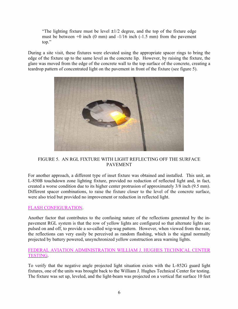
“The lighting fixture must be level ±1/2 degree, and the top of the fixture edge must be between +0 inch (0 mm) and -1/16 inch (-1.5 mm) from the pavement top.”
During a site visit, these fixtures were elevated using the appropriate spacer rings to bring the edge of the fixture up to the same level as the concrete lip. However, by raising the fixture, the glare was moved from the edge of the concrete wall to the top surface of the concrete, creating a teardrop pattern of concentrated light on the pavement in front of the fixture (see figure 5).
FIGURE 5. AN RGL FIXTURE WITH LIGHT REFLECTING OFF THE SURFACE PAVEMENT
For another approach, a different type of inset fixture was obtained and installed. This unit, an L-850B touchdown zone lighting fixture, provided no reduction of reflected light and, in fact, created a worse condition due to its higher center protrusion of approximately 3/8 inch (9.5 mm). Different spacer combinations, to raise the fixture closer to the level of the concrete surface, were also tried but provided no improvement or reduction in reflected light. FLASH CONFIGURATION.
Another factor that contributes to the confusing nature of the reflections generated by the in-pavement RGL system is that the row of yellow lights are configured so that alternate lights are pulsed on and off, to provide a so-called wig-wag pattern. However, when viewed from the rear, the reflections can very easily be perceived as random flashing, which is the signal normally projected by battery powered, unsynchronized yellow construction area warning lights. FEDERAL AVIATION ADMINISTRATION WILLIAM J. HUGHES TECHNICAL CENTER TESTING.
To verify that the negative angle projected light situation exists with the L-852G guard light fixtures, one of the units was brought back to the William J. Hughes Technical Center for testing. The fixture was set up, leveled, and the light-beam was projected on a vertical flat surface 10 feet
6
(3.05 m) directly in front of the unit. A theodolite was used to measure the vertical height difference between the height of the outer edge of the leveled L-852G fixture and the height of the bottom cutoff of the light pattern projected. The cutoff point was found to be, at a distance of 10 feet, 0.44 feet below the level of the fixture’s outer edge. These height values showed that the bottom edge of the L-852B unit’s projected light beam is at a negative angle of 2.52 degrees and will, regardless of the height at which it is installed, cause reflections rearward from either the vertical edge or horizontal surface of the surrounding concrete. This procedure was later conducted with sample fixtures from other manufacturers, and resulted in comparable measurements of light being emitted at negative angles. CONSIDERED SOLUTIONS.
Having considered the several causes for the reflections, the William J. Hughes Technical Center provided three possible solutions for alleviating or reducing the problem. In order of descending effectiveness, possible remedies offered were as follows. 1. The specifications for the L-852G guard light fixture should be changed to contain a
requirement that “no light shall be emitted at negative angles” to ensure a photometric or physical cutoff point that will prevent reflections from a correctly installed fixture. As such, a modification will most likely involve a slight reduction in overall projected light intensity and a reduction in specified intensity for the +1 to +10 degree beam angles (1000 candelas) may be required. A benefit of such a change to the advisory circular would be that the manufacturers would be encouraged to develop and produce L-852G fixtures having even lower above-pavement (top of fixture) projections than available at present. While this is the most effective remedy for the reflection problem, it is also the one that would be the most difficult, and expensive, to implement. Initial discussions with fixture manufacturers have shown that they may be reluctant to pursue such a modified fixture because of the low market demand for such fixtures. There are simply not enough inset RGL installations to warrant the development of a custom fixture.
2. A change or modification to existing L-852G fixture lenses, to reduce the physical height
of the lens and, thus, heighten the lower cutoff angle of the beam to 0 degrees, would significantly reduce the amount of reflection from the horizontal surface of the taxiway immediately in front of the fixture. Reflections from the vertical walls of the hole would still be a problem, however, unless the outer edge of the fixture is maintained within the recommended depth limit or 1/16 inch. Such modified lenses might be retrofitted to fixtures when they are disassembled for airport refurbishment. This too will require physical modifications to the fixture and significantly diminish the photometric characteristics of the light projected from the fixture.
3. A change to permit the use of a steady-flashing (all fixtures flash in unison) in-pavement
guard light configuration would eliminate the random flashing reflection impression that some pilots perceive and are confused by. A strong bold line of yellow flashing or steady lights, flanked by the wig-wag elevated lights on either side, should certainly be sufficiently attention-getting for the purpose.
7

At the time these solutions were suggested, each of the manufacturers that produce the L-852G fixture was again contacted for comments. As was previously indicated, each of the manufacturers said they would very likely abandon the fixture as a product, as it would require significant development costs to design a fixture that performs as suggested. Since the overall reflection problem stems from both the physical design and photometric requirements of the L-852G fixtures, as suggested in remedy 1 and 2, it was decided that the next most easily implemented solution may be in finding an acceptable variation of the flash presentation. To investigate the possibility of varying the flash pattern, an on-site evaluation was conducted at ORD to determine if an alternate flash pattern would provide the desired solution.
EVALUATION
On the evening of November 19, 2001, the original investigative team from the FAA Great Lakes Region and the FAA William J. Hughes Technical Center, the pilots from American Airlines, and representatives of other interested organizations, met at ORD to conduct an evaluation of the following lighting configurations: 1. Standard alternate flashing lights (wig-wag presentation) 2. Simultaneously flashing lights (pulsing presentation) 3. Steady-burning lights (solid line of lights) 4. A set of randomly flashing yellow barricade lights (to provide an example of the
construction light pattern that was confused with the runway guard lights.) United Airlines was generous enough to provide a Chicago-based pilot and a Boeing 747-200 aircraft to support the nighttime taxiing evaluation. The test was accomplished on a closed runway and adjacent taxiways between the hours of 11:00 p.m. to 1:00 a.m. A taxi route was chosen that included cockpit and port-side window views of the three inset RGL configurations and the sample barricade light array: first from the back (runway/arrival) side and then from the front (taxiway/departure) side. Due to the confined cockpit area, the test participants had to take turns to observe the lighting from the pilot’s viewpoint. During the test, it was most fortunate that low-visibility weather conditions of 1800-foot runway visual range in fog were encountered. This provided a most realistic, critical taxiing situation.
TEST RESULTS
An informal debriefing was held on the ramp after the evaluation session, and the consensus was as follows. 1. When viewed from the rear (runway) side, the appearance of the wig-wag (alternating
flashing lights) configuration was such that under certain circumstances, it might easily be interpreted as, or confused with, randomly flashing yellow construction or barricade
8

lights. This would be especially true if the guard lights were viewed from the cockpit of a smaller aircraft at short range when only a portion of the lighting array was within the pilot’s direct field of vision.
2. When viewed from the rear (runway) side, the appearance of the pulsing (simultaneously flashing) configuration was such that no sensation or perception of randomly flashing construction or barricade lights was noted. It was felt that this would also be true regardless of the aircraft size or distance from the lights.
3. When viewed from the rear (runway) side, the appearance of the steady-burning light configuration, as expected, showed there could be no question or confusion with an array of randomly flashing barricade lights. It was noted, however, that at times the steady lights became lost among the numerous steady-burning taxiway and runway edge and centerline light fixtures. While it eliminated the flashing aspect of the problem, it did not produce the attention-getting appearance that the in-pavement RGL system was designed to produce.
4. When viewed from the front (taxiway) side, all three configurations provided a bold indication of the holding position location. The line of steady-burning lights, however, was not quite as unique as the other two configurations and could, conceivably, become immersed or rendered less effective by other nearby steady-burning yellow lights (i.e., runway lights on low intensity). The simultaneously flashing light configuration provided the bold and unique pattern required without the possibility of confusion when viewed from the runway side.
CONCLUSIONS
From the results of this evaluation, and from a study of pertinent Federal Aviation Administration Advisory Circulars, the following conclusions were made. 1. The L-852G lighting fixture, in its current design, will always generate light that is
directed downward towards the pavement in front of the fixture or onto the front lip of the fixture. No modifications are possible to eliminate this problem without sacrificing the intended photometric values of the fixture. A completely new fixture, with revised photometric requirements, would be necessary to perform as required without generating the downward shining light.
2. Variations in installation technique and workmanship, while contributing to the
backscattered lighting problem, were found not to be the primary cause of the problem. While attempts to vary the installation height and surface finish in front of the fixture did show minimal reductions in the amount of reflected light, it did not solve the problem of the light being seen from the runway side of the fixtures.
3. The problem was common with all manufacturers, with all types of L-852G fixtures. The
problem could not be isolated to one vendor or one type of fixture.
9

4. The problems encountered with the L-852G are isolated to that fixture style only. The only other applications for the unidirectional inset lights have been as touchdown zone lights and stopbar lights. In this scenario, aircraft only proceed toward the lights and not approach them from the rear where reflected light might be a consideration. Runway guard lights (RGL), however, are approached from either direction, resulting in a unique problem of reflections to the rear of the fixtures.
5. The simultaneous flashing configuration was determined to be the most effective
configuration because it provided the attention-getting appearance that the in-pavement RGL system was designed to produce, and was not confused for a construction barricade when viewed from the runway side.
6. The final solution to the problem encountered at Chicago O’Hare International Airport
was to reconfigure the flash pattern of the in-pavement RGL system so that it flashes in unison, eliminating the confusing random yellow flashing pattern that is viewed from the runway side of the fixture, while still maintaining the intended integrity of the system when viewed from the taxiway side.
10