Embed Size (px)
Citation preview
Global United Technology Services Co., Ltd.
Report No.: GTS201903000025E05
The CE mark as shown below can be used, under the responsibility of the manufacturer, after completion of an EC Declaration of
Conformity and compliance with all relevant EC Directives. The protection requirements with respect to electromagnetic compatibility
contained in Directive 2014/30/EU are considered.
Robinson Lo
Laboratory Manager This results shown in this test report refer only to the sample(s) tested, this test report cannot be reproduced, except in full, without prior written permission of the company. The report would be invalid without specific stamp of test institute and the signatures of compiler and approver
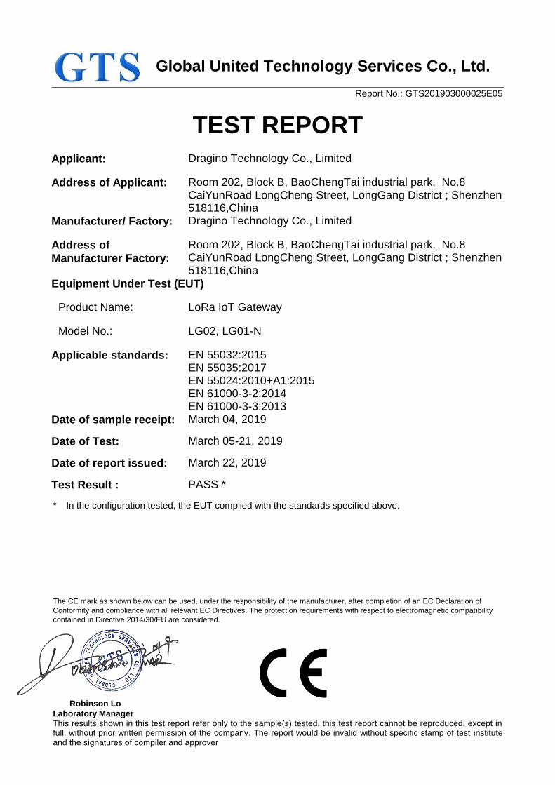
TEST REPORT
Applicant: Dragino Technology Co., Limited
Address of Applicant: Room 202, Block B, BaoChengTai industrial park, No.8 CaiYunRoad LongCheng Street, LongGang District ; Shenzhen 518116,China
Manufacturer/ Factory: Dragino Technology Co., Limited
Address of
Manufacturer Factory:
Room 202, Block B, BaoChengTai industrial park, No.8 CaiYunRoad LongCheng Street, LongGang District ; Shenzhen 518116,China
Equipment Under Test (EUT)
Product Name: LoRa IoT Gateway
Model No.: LG02, LG01-N
Applicable standards: EN 55032:2015 EN 55035:2017 EN 55024:2010+A1:2015 EN 61000-3-2:2014 EN 61000-3-3:2013
Date of sample receipt: March 04, 2019
Date of Test: March 05-21, 2019
Date of report issued: March 22, 2019
Test Result : PASS *
* In the configuration tested, the EUT complied with the standards specified above.
Report No.: GTS201903000025E05
Global United Technology Service Co., Ltd. No. 123-128, Tower A, Jinyuan Business Building, No.2, Laodong Industrial Zone, Xixiang Road, Baoan District, Shenzhen, Guangdong, China Telephone: +86 (0) 755 2779 8480 Fax: +86 (0) 755 2779 8960 Page 2 of 38
2 Version
Version No. Date Description
00 March 22, 2019 Original
Prepared By: Date: March 22, 2019
Project Engineer
Check By: Date: March 22, 2019
Reviewer
Report No.: GTS201903000025E05
Global United Technology Service Co., Ltd. No. 123-128, Tower A, Jinyuan Business Building, No.2, Laodong Industrial Zone, Xixiang Road, Baoan District, Shenzhen, Guangdong, China
Telephone: +86 (0) 755 2779 8480 Fax: +86 (0) 755 2779 8960 Page 3 of 38
3 Contents
1 COVER PAGE ...........................................................................................................................................1
2 VERSION ...................................................................................................................................................2
3 CONTENTS ...............................................................................................................................................3
4 TEST SUMMARY ......................................................................................................................................4
5 GENERAL INFORMATION .......................................................................................................................5
5.1 GENERAL DESCRIPTION OF EUT ..........................................................................................................5 5.2 TEST MODE AND TEST VOLTAGE ...........................................................................................................5 5.3 DESCRIPTION OF SUPPORT UNITS ........................................................................................................5 5.4 DEVIATION FROM STANDARDS ..............................................................................................................5 5.5 ABNORMALITIES FROM STANDARD CONDITIONS ....................................................................................6 5.6 MONITORING OF EUT FOR ALL IMMUNITY TEST .....................................................................................6 5.7 TEST FACILITY.....................................................................................................................................6 5.8 TEST LOCATION...................................................................................................................................6
6 TEST INSTRUMENTS LIST ......................................................................................................................7
7 EMISSION TEST RESULTS ...................................................................................................................11
7.1 RADIATED EMISSION ..........................................................................................................................11 7.2 CONDUCTED EMISSION ......................................................................................................................17
7.2.1 AC port ..................................................................................................................................................... 17 7.2.2 Signal ports and Telecommunication ports ............................................................................................ 20
7.3 HARMONIC EMISSION .........................................................................................................................22 7.4 FLICKER EMISSION ............................................................................................................................22
8 IMMUNITY TEST RESULTS ...................................................................................................................23
8.1 PERFORMANCE CRITERIA DESCRIPTION IN CLAUSE 7 OF EN 55024/EN 55035 ...................................23 8.2 ELECTROSTATIC DISCHARGE ..............................................................................................................24 8.3 RADIO-FREQUENCY ELECTROMAGNETIC FIELD AMPLITUDE MODULATED ...............................................26 8.4 ELECTRICAL FAST TRANSIENTS ...........................................................................................................28
8.4.1 AC port ..................................................................................................................................................... 28 8.4.2 Signal ports and Telecommunication ports ............................................................................................ 30
8.5 SURGES ............................................................................................................................................32 8.5.1 AC ports .................................................................................................................................................... 32 8.5.2 Signal ports and Telecommunication ports ............................................................................................ 34
8.6 RADIO-FREQUENCY CONTINUOUS CONDUCTED ....................................................................................35 8.6.1 AC port ..................................................................................................................................................... 35 8.6.2 Signal ports and Telecommunication ports ............................................................................................ 36
8.7 VOLTAGE DIPS AND VOLTAGE INTERRUPTIONS ....................................................................................37
9 TEST SETUP PHOTO .............................................................................................................................38
10 EUT CONSTRUCTIONAL DETAILS .......................................................................................................38
Report No.: GTS201903000025E05
Global United Technology Service Co., Ltd. No. 123-128, Tower A, Jinyuan Business Building, No.2, Laodong Industrial Zone, Xixiang Road, Baoan District, Shenzhen, Guangdong, China
Telephone: +86 (0) 755 2779 8480 Fax: +86 (0) 755 2779 8960 Page 4 of 38
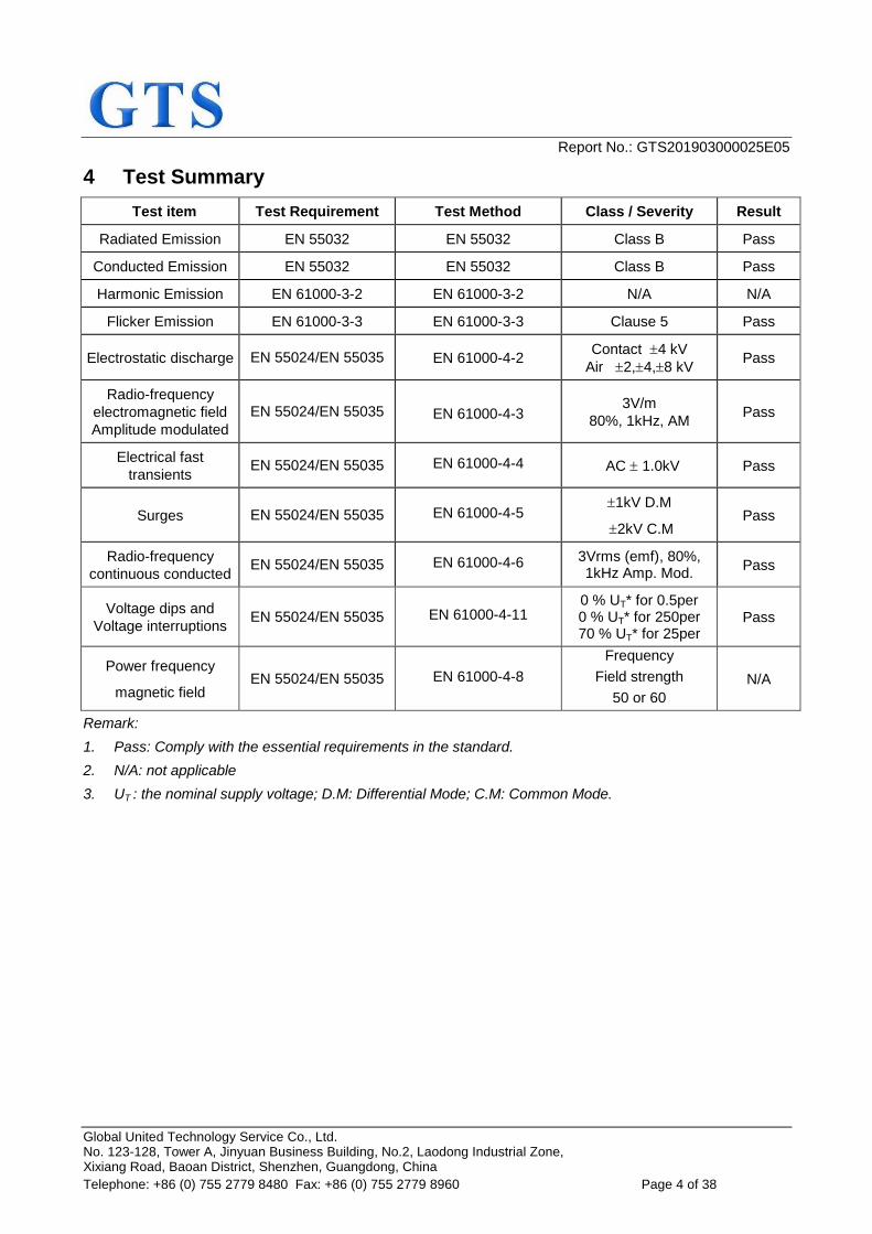
4 Test Summary
Test item Test Requirement Test Method Class / Severity Result
Radiated Emission EN 55032 EN 55032 Class B Pass
Conducted Emission EN 55032 EN 55032 Class B Pass
Harmonic Emission EN 61000-3-2 EN 61000-3-2 N/A N/A
Flicker Emission EN 61000-3-3 EN 61000-3-3 Clause 5 Pass
Electrostatic discharge EN 55024/EN 55035 EN 61000-4-2 Contact 4 kV
Air 2,4,8 kV Pass
Radio-frequency
electromagnetic field
Amplitude modulated
EN 55024/EN 55035 EN 61000-4-3 3V/m
80%, 1kHz, AM Pass
Electrical fast
transients EN 55024/EN 55035 EN 61000-4-4 AC 1.0kV Pass
Surges EN 55024/EN 55035 EN 61000-4-5 1kV D.M
2kV C.M Pass
Radio-frequency
continuous conducted EN 55024/EN 55035 EN 61000-4-6 3Vrms (emf), 80%,
1kHz Amp. Mod. Pass
Voltage dips and
Voltage interruptions EN 55024/EN 55035 EN 61000-4-11
0 % UT* for 0.5per 0 % UT* for 250per 70 % UT* for 25per
Pass
Power frequency
magnetic field EN 55024/EN 55035 EN 61000-4-8
Frequency
Field strength
50 or 60
N/A
Remark:
1. Pass: Comply with the essential requirements in the standard.
2. N/A: not applicable
3. UT : the nominal supply voltage; D.M: Differential Mode; C.M: Common Mode.
Report No.: GTS201903000025E05
Global United Technology Service Co., Ltd. No. 123-128, Tower A, Jinyuan Business Building, No.2, Laodong Industrial Zone, Xixiang Road, Baoan District, Shenzhen, Guangdong, China
Telephone: +86 (0) 755 2779 8480 Fax: +86 (0) 755 2779 8960 Page 5 of 38
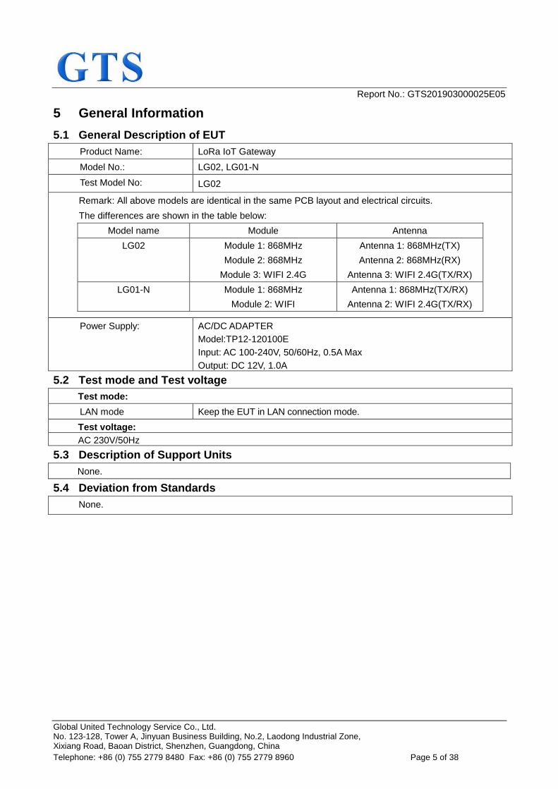
5 General Information
5.1 General Description of EUT
Product Name: LoRa IoT Gateway
Model No.: LG02, LG01-N
Test Model No: LG02
Remark: All above models are identical in the same PCB layout and electrical circuits.
The differences are shown in the table below:
Model name Module Antenna
LG02 Module 1: 868MHz
Module 2: 868MHz
Module 3: WIFI 2.4G
Antenna 1: 868MHz(TX)
Antenna 2: 868MHz(RX)
Antenna 3: WIFI 2.4G(TX/RX)
LG01-N Module 1: 868MHz
Module 2: WIFI
Antenna 1: 868MHz(TX/RX)
Antenna 2: WIFI 2.4G(TX/RX)
Power Supply: AC/DC ADAPTER
Model:TP12-120100E
Input: AC 100-240V, 50/60Hz, 0.5A Max
Output: DC 12V, 1.0A
5.2 Test mode and Test voltage
Test mode:
LAN mode Keep the EUT in LAN connection mode.
Test voltage:
AC 230V/50Hz
5.3 Description of Support Units
None.
5.4 Deviation from Standards
None.
Report No.: GTS201903000025E05
Global United Technology Service Co., Ltd. No. 123-128, Tower A, Jinyuan Business Building, No.2, Laodong Industrial Zone, Xixiang Road, Baoan District, Shenzhen, Guangdong, China
Telephone: +86 (0) 755 2779 8480 Fax: +86 (0) 755 2779 8960 Page 6 of 38
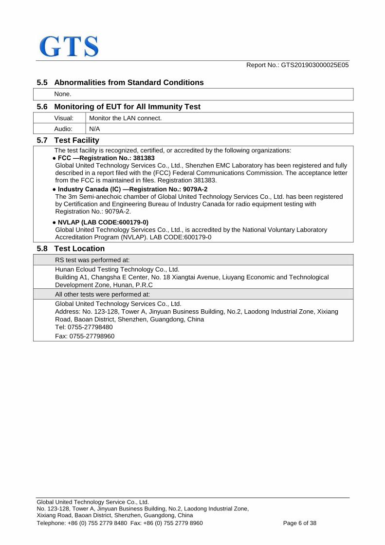
5.5 Abnormalities from Standard Conditions
None.
5.6 Monitoring of EUT for All Immunity Test
Visual: Monitor the LAN connect.
Audio: N/A
5.7 Test Facility
The test facility is recognized, certified, or accredited by the following organizations:
● FCC —Registration No.: 381383 Global United Technology Services Co., Ltd., Shenzhen EMC Laboratory has been registered and fully described in a report filed with the (FCC) Federal Communications Commission. The acceptance letter from the FCC is maintained in files. Registration 381383.
● Industry Canada (IC) —Registration No.: 9079A-2 The 3m Semi-anechoic chamber of Global United Technology Services Co., Ltd. has been registered by Certification and Engineering Bureau of Industry Canada for radio equipment testing with Registration No.: 9079A-2.
● NVLAP (LAB CODE:600179-0) Global United Technology Services Co., Ltd., is accredited by the National Voluntary Laboratory Accreditation Program (NVLAP). LAB CODE:600179-0
5.8 Test Location
RS test was performed at:
Hunan Ecloud Testing Technology Co., Ltd.
Building A1, Changsha E Center, No. 18 Xiangtai Avenue, Liuyang Economic and Technological
Development Zone, Hunan, P.R.C
All other tests were performed at:
Global United Technology Services Co., Ltd.
Address: No. 123-128, Tower A, Jinyuan Business Building, No.2, Laodong Industrial Zone, Xixiang
Road, Baoan District, Shenzhen, Guangdong, China
Tel: 0755-27798480
Fax: 0755-27798960
Report No.: GTS201903000025E05
Global United Technology Service Co., Ltd. No. 123-128, Tower A, Jinyuan Business Building, No.2, Laodong Industrial Zone, Xixiang Road, Baoan District, Shenzhen, Guangdong, China
Telephone: +86 (0) 755 2779 8480 Fax: +86 (0) 755 2779 8960 Page 7 of 38
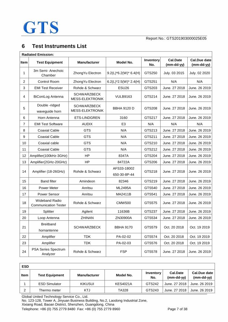
6 Test Instruments List
Radiated Emission:
Item Test Equipment Manufacturer Model No. Inventory
No.
Cal.Date
(mm-dd-yy)
Cal.Due date
(mm-dd-yy)
1 3m Semi- Anechoic
Chamber ZhongYu Electron 9.2(L)*6.2(W)* 6.4(H) GTS250 July. 03 2015 July. 02 2020
2 Control Room ZhongYu Electron 6.2(L)*2.5(W)* 2.4(H) GTS251 N/A N/A
3 EMI Test Receiver Rohde & Schwarz ESU26 GTS203 June. 27 2018 June. 26 2019
4 BiConiLog Antenna SCHWARZBECK
MESS-ELEKTRONIK VULB9163 GTS214 June. 27 2018 June. 26 2019
5 Double -ridged
waveguide horn
SCHWARZBECK
MESS-ELEKTRONIK BBHA 9120 D GTS208 June. 27 2018 June. 26 2019
6 Horn Antenna ETS-LINDGREN 3160 GTS217 June. 27 2018 June. 26 2019
7 EMI Test Software AUDIX E3 N/A N/A N/A
8 Coaxial Cable GTS N/A GTS213 June. 27 2018 June. 26 2019
9 Coaxial Cable GTS N/A GTS211 June. 27 2018 June. 26 2019
10 Coaxial cable GTS N/A GTS210 June. 27 2018 June. 26 2019
11 Coaxial Cable GTS N/A GTS212 June. 27 2018 June. 26 2019
12 Amplifier(100kHz-3GHz) HP 8347A GTS204 June. 27 2018 June. 26 2019
13 Amplifier(2GHz-20GHz) HP 84722A GTS206 June. 27 2018 June. 26 2019
14 Amplifier (18-26GHz) Rohde & Schwarz AFS33-18002
650-30-8P-44 GTS218 June. 27 2018 June. 26 2019
15 Band filter Amindeon 82346 GTS219 June. 27 2018 June. 26 2019
16 Power Meter Anritsu ML2495A GTS540 June. 27 2018 June. 26 2019
17 Power Sensor Anritsu MA2411B GTS541 June. 27 2018 June. 26 2019
18 Wideband Radio
Communication Tester Rohde & Schwarz CMW500 GTS575 June. 27 2018 June. 26 2019
19 Splitter Agilent 11636B GTS237 June. 27 2018 June. 26 2019
20 Loop Antenna ZHINAN ZN30900A GTS534 June. 27 2018 June. 26 2019
21 Breitband
hornantenne SCHWARZBECK BBHA 9170 GTS579 Oct. 20 2018 Oct. 19 2019
22 Amplifier TDK PA-02-02 GTS574 Oct. 20 2018 Oct. 19 2019
23 Amplifier TDK PA-02-03 GTS576 Oct. 20 2018 Oct. 19 2019
24 PSA Series Spectrum
Analyzer Rohde & Schwarz FSP GTS578 June. 27 2018 June. 26 2019
ESD
Item Test Equipment Manufacturer Model No. Inventory
No.
Cal.Date
(mm-dd-yy)
Cal.Due date
(mm-dd-yy)
1 ESD Simulator KIKUSUI KES4021A GTS242 June. 27 2018 June. 26 2019
2 Thermo meter KTJ TA328 GTS243 June. 27 2018 June. 26 2019
Report No.: GTS201903000025E05
Global United Technology Service Co., Ltd. No. 123-128, Tower A, Jinyuan Business Building, No.2, Laodong Industrial Zone, Xixiang Road, Baoan District, Shenzhen, Guangdong, China
Telephone: +86 (0) 755 2779 8480 Fax: +86 (0) 755 2779 8960 Page 8 of 38
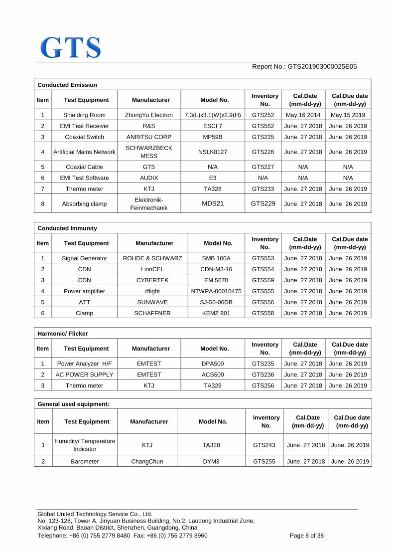
Conducted Emission
Item Test Equipment Manufacturer Model No. Inventory
No.
Cal.Date
(mm-dd-yy)
Cal.Due date
(mm-dd-yy)
1 Shielding Room ZhongYu Electron 7.3(L)x3.1(W)x2.9(H) GTS252 May.16 2014 May.15 2019
2 EMI Test Receiver R&S ESCI 7 GTS552 June. 27 2018 June. 26 2019
3 Coaxial Switch ANRITSU CORP MP59B GTS225 June. 27 2018 June. 26 2019
4 Artificial Mains Network SCHWARZBECK
MESS NSLK8127 GTS226 June. 27 2018 June. 26 2019
5 Coaxial Cable GTS N/A GTS227 N/A N/A
6 EMI Test Software AUDIX E3 N/A N/A N/A
7 Thermo meter KTJ TA328 GTS233 June. 27 2018 June. 26 2019
8 Absorbing clamp Elektronik-
Feinmechanik MDS21 GTS229 June. 27 2018 June. 26 2019
Conducted Immunity
Item Test Equipment Manufacturer Model No. Inventory
No.
Cal.Date
(mm-dd-yy)
Cal.Due date
(mm-dd-yy)
1 Signal Generator ROHDE & SCHWARZ SMB 100A GTS553 June. 27 2018 June. 26 2019
2 CDN LionCEL CDN-M3-16 GTS554 June. 27 2018 June. 26 2019
3 CDN CYBERTEK EM 5070 GTS559 June. 27 2018 June. 26 2019
4 Power amplifier rflight NTWPA-00010475 GTS555 June. 27 2018 June. 26 2019
5 ATT SUNWAVE SJ-50-06DB GTS556 June. 27 2018 June. 26 2019
6 Clamp SCHAFFNER KEMZ 801 GTS558 June. 27 2018 June. 26 2019
Harmonic/ Flicker
Item Test Equipment Manufacturer Model No. Inventory
No.
Cal.Date
(mm-dd-yy)
Cal.Due date
(mm-dd-yy)
1 Power Analyzer H/F EMTEST DPA500 GTS235 June. 27 2018 June. 26 2019
2 AC POWER SUPPLY EMTEST ACS500 GTS236 June. 27 2018 June. 26 2019
3 Thermo meter KTJ TA328 GTS256 June. 27 2018 June. 26 2019
General used equipment:
Item Test Equipment Manufacturer Model No. Inventory
No.
Cal.Date
(mm-dd-yy)
Cal.Due date
(mm-dd-yy)
1 Humidity/ Temperature
Indicator KTJ TA328 GTS243 June. 27 2018 June. 26 2019
2 Barometer ChangChun DYM3 GTS255 June. 27 2018 June. 26 2019
Report No.: GTS201903000025E05
Global United Technology Service Co., Ltd. No. 123-128, Tower A, Jinyuan Business Building, No.2, Laodong Industrial Zone, Xixiang Road, Baoan District, Shenzhen, Guangdong, China
Telephone: +86 (0) 755 2779 8480 Fax: +86 (0) 755 2779 8960 Page 9 of 38
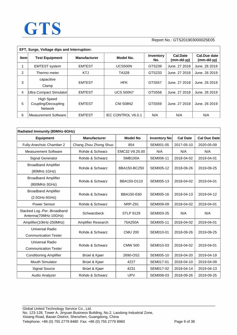
Radiated Immunity (80MHz-6GHz)
Equipment Manufacturer Model No Inventory No Cal Date Cal Due Date
Fully-Anechoic Chamber 2 Chang Zhou Zhong Shuo 854 SEM001-05 2017-05-10 2020-05-09
Measurement Software Rohde & Schwarz EMC32 V9.25.00 N/A N/A N/A
Signal Generator Rohde & Schwarz SMB100A SEM006-11 2018-04-02 2019-04-01
Broadband Amplifier
(80MHz-1GHz) Rohde & Schwarz BBA150-BC250 SEM005-12 2018-09-26 2019-09-25
Broadband Amplifier
(800MHz-3GHz) Rohde & Schwarz BBA150-D110 SEM005-13 2018-04-02 2019-04-01
Broadband Amplifier
(2.5GHz-6GHz) Rohde & Schwarz BBA150-E60 SEM005-16 2018-04-13 2019-04-12
Power Sensor Rohde & Schwarz NRP-Z91 SEM009-09 2018-04-02 2019-04-01
Stacked Log.-Per.-Broadband
Antenna(70MHz-10GHz) Schwarzbeck STLP 9129 SEM003-25 N/A N/A
Amplifier(10kHz-250MHz) Amplifier Research 75A250A SEM005-11 2018-04-02 2019-04-01
Universal Radio
Communication Tester Rohde & Schwarz CMU 200 SEM010-01 2018-09-26 2019-09-25
Universal Radio
Communication Tester Rohde & Schwarz CMW 500 SEM010-03 2018-04-02 2019-04-01
Conditioning Amplifier Brüel & Kjaer 2690-OS2 SEM005-10 2018-04-20 2019-04-19
Mouth Simulator Brüel & Kjaer 4227 SEM017-01 2018-04-10 2019-04-09
Signal Source Brüel & Kjaer 4231 SEM017-02 2018-04-14 2019-04-13
Audio Analyzer Rohde & Schwarz UPV SEM008-03 2018-09-26 2019-09-25
EFT, Surge, Voltage dips and Interruption:
Item Test Equipment Manufacturer Model No. Inventory
No.
Cal.Date
(mm-dd-yy)
Cal.Due date
(mm-dd-yy)
1 EMTEST system EMTEST UCS500N GTS239 June. 27 2018 June. 26 2019
2 Thermo meter KTJ TA328 GTS233 June. 27 2018 June. 26 2019
3 capacitive
Clamp EMTEST HFK GTS557 June. 27 2018 June. 26 2019
4 Ultra Compact Simulator EMTEST UCS 500N7 GTS558 June. 27 2018 June. 26 2019
5
High Speed
Coupling/Decoupling
Network
EMTEST CNI 508N2 GTS559 June. 27 2018 June. 26 2019
6 Measurement Software EMTEST IEC CONTROL V6.0.1 N/A N/A N/A
Report No.: GTS201903000025E05
Global United Technology Service Co., Ltd. No. 123-128, Tower A, Jinyuan Business Building, No.2, Laodong Industrial Zone, Xixiang Road, Baoan District, Shenzhen, Guangdong, China
Telephone: +86 (0) 755 2779 8480 Fax: +86 (0) 755 2779 8960 Page 10 of 38
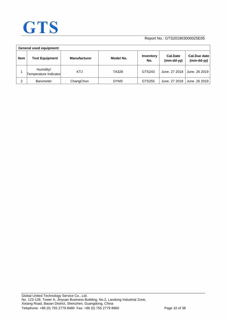
General used equipment:
Item Test Equipment Manufacturer Model No. Inventory
No.
Cal.Date
(mm-dd-yy)
Cal.Due date
(mm-dd-yy)
1 Humidity/
Temperature Indicator KTJ TA328 GTS243 June. 27 2018 June. 26 2019
2 Barometer ChangChun DYM3 GTS255 June. 27 2018 June. 26 2019
Report No.: GTS201903000025E05
Global United Technology Service Co., Ltd. No. 123-128, Tower A, Jinyuan Business Building, No.2, Laodong Industrial Zone, Xixiang Road, Baoan District, Shenzhen, Guangdong, China
Telephone: +86 (0) 755 2779 8480 Fax: +86 (0) 755 2779 8960 Page 11 of 38
7 Emission Test Results
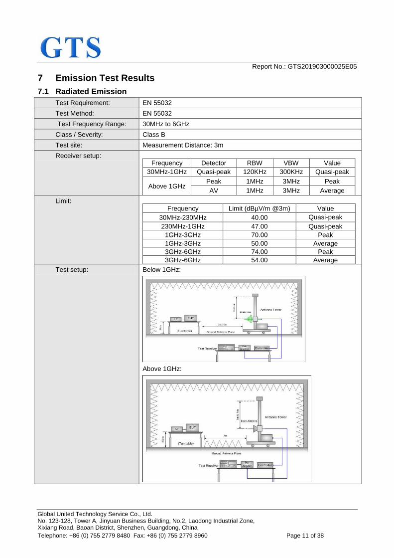
7.1 Radiated Emission
Test Requirement: EN 55032
Test Method: EN 55032
Test Frequency Range: 30MHz to 6GHz
Class / Severity: Class B Class B
Test site: Measurement Distance: 3m
Receiver setup:
Frequency Detector RBW VBW Value
30MHz-1GHz Quasi-peak 120KHz 300KHz Quasi-peak
Above 1GHz Peak 1MHz 3MHz Peak
AV 1MHz 3MHz Average
Limit:
Frequency Limit (dBµV/m @3m) Value
30MHz-230MHz 40.00 Quasi-peak
230MHz-1GHz 47.00 Quasi-peak
1GHz-3GHz 70.00 Peak
1GHz-3GHz 50.00 Average
3GHz-6GHz 74.00 Peak
3GHz-6GHz 54.00 Average
Test setup: Below 1GHz:
Above 1GHz:
Report No.: GTS201903000025E05
Global United Technology Service Co., Ltd. No. 123-128, Tower A, Jinyuan Business Building, No.2, Laodong Industrial Zone, Xixiang Road, Baoan District, Shenzhen, Guangdong, China
Telephone: +86 (0) 755 2779 8480 Fax: +86 (0) 755 2779 8960 Page 12 of 38
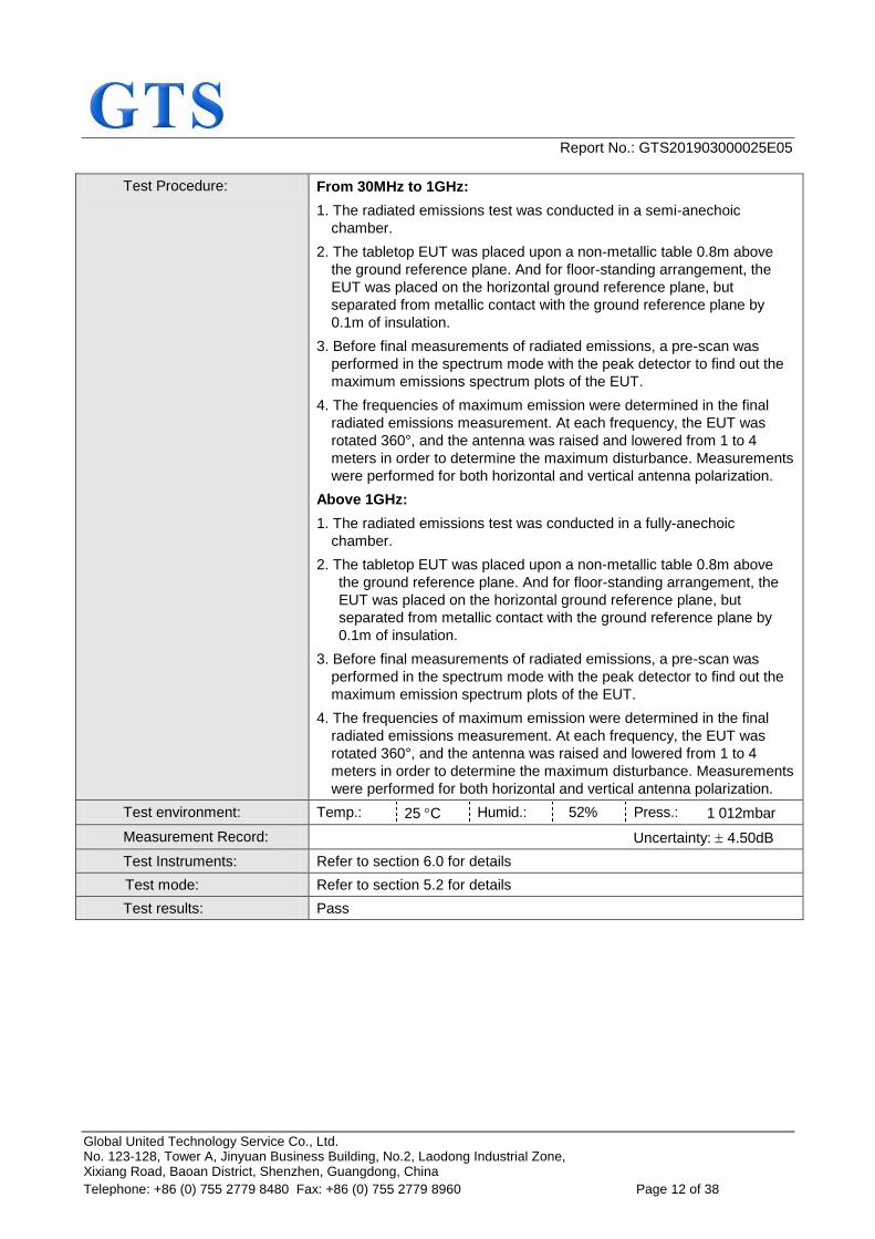
Test Procedure: From 30MHz to 1GHz:
1. The radiated emissions test was conducted in a semi-anechoic
chamber.
2. The tabletop EUT was placed upon a non-metallic table 0.8m above
the ground reference plane. And for floor-standing arrangement, the
EUT was placed on the horizontal ground reference plane, but
separated from metallic contact with the ground reference plane by
0.1m of insulation.
3. Before final measurements of radiated emissions, a pre-scan was
performed in the spectrum mode with the peak detector to find out the
maximum emissions spectrum plots of the EUT.
4. The frequencies of maximum emission were determined in the final
radiated emissions measurement. At each frequency, the EUT was
rotated 360°, and the antenna was raised and lowered from 1 to 4
meters in order to determine the maximum disturbance. Measurements
were performed for both horizontal and vertical antenna polarization.
Above 1GHz:
1. The radiated emissions test was conducted in a fully-anechoic
chamber.
2. The tabletop EUT was placed upon a non-metallic table 0.8m above
the ground reference plane. And for floor-standing arrangement, the
EUT was placed on the horizontal ground reference plane, but
separated from metallic contact with the ground reference plane by
0.1m of insulation.
3. Before final measurements of radiated emissions, a pre-scan was
performed in the spectrum mode with the peak detector to find out the
maximum emission spectrum plots of the EUT.
4. The frequencies of maximum emission were determined in the final
radiated emissions measurement. At each frequency, the EUT was
rotated 360°, and the antenna was raised and lowered from 1 to 4
meters in order to determine the maximum disturbance. Measurements
were performed for both horizontal and vertical antenna polarization.
Test environment: Temp.: 25 C Humid.: 52% Press.: 1 012mbar
Measurement Record: Uncertainty: 4.50dB
Test Instruments: Refer to section 6.0 for details
Test mode: Refer to section 5.2 for details
Test results: Pass
Report No.: GTS201903000025E05
Global United Technology Service Co., Ltd. No. 123-128, Tower A, Jinyuan Business Building, No.2, Laodong Industrial Zone, Xixiang Road, Baoan District, Shenzhen, Guangdong, China
Telephone: +86 (0) 755 2779 8480 Fax: +86 (0) 755 2779 8960 Page 13 of 38
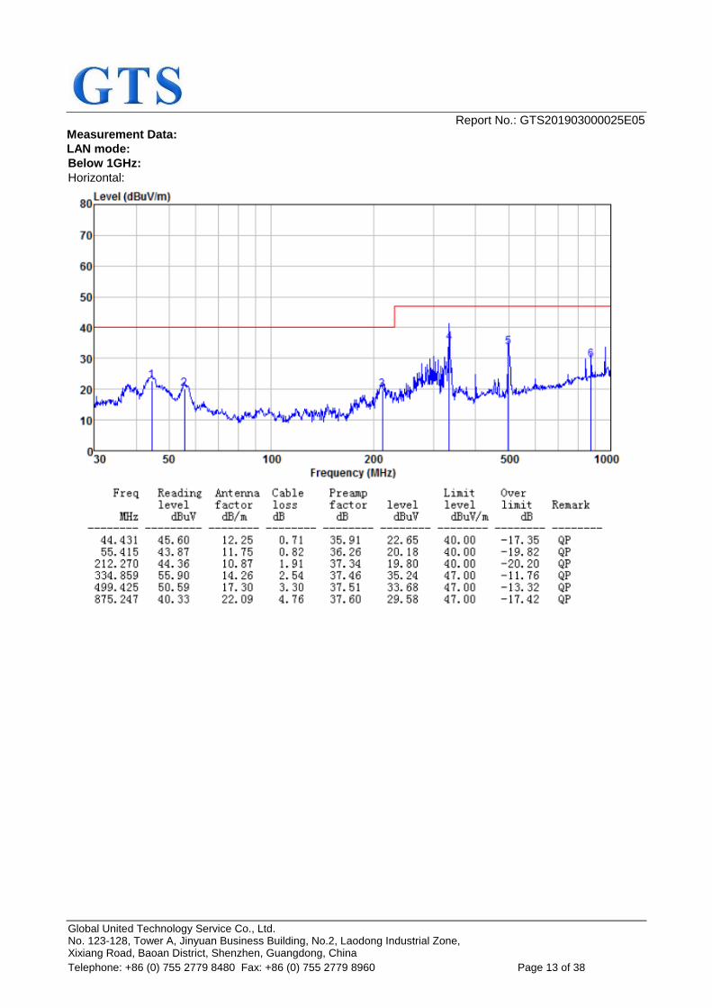
Measurement Data:
LAN mode:
Below 1GHz:
Horizontal:
Report No.: GTS201903000025E05
Global United Technology Service Co., Ltd. No. 123-128, Tower A, Jinyuan Business Building, No.2, Laodong Industrial Zone, Xixiang Road, Baoan District, Shenzhen, Guangdong, China
Telephone: +86 (0) 755 2779 8480 Fax: +86 (0) 755 2779 8960 Page 14 of 38
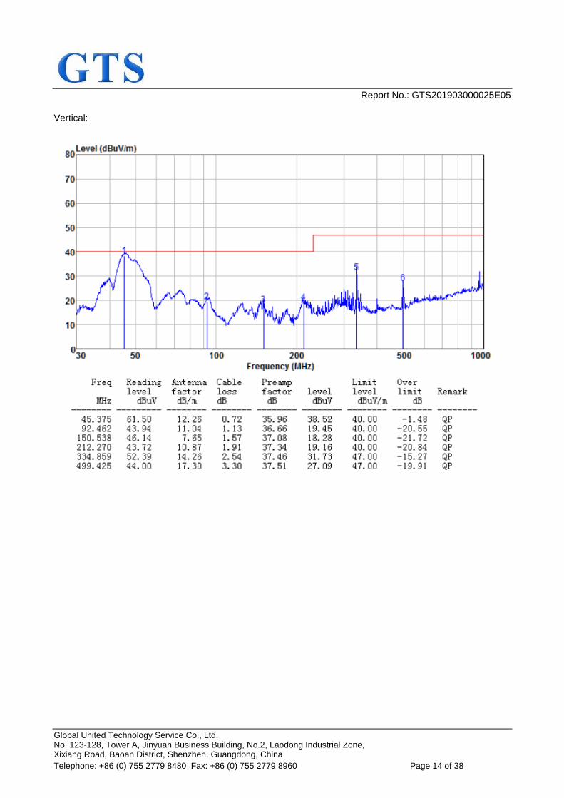
Vertical:
Report No.: GTS201903000025E05
Global United Technology Service Co., Ltd. No. 123-128, Tower A, Jinyuan Business Building, No.2, Laodong Industrial Zone, Xixiang Road, Baoan District, Shenzhen, Guangdong, China
Telephone: +86 (0) 755 2779 8480 Fax: +86 (0) 755 2779 8960 Page 15 of 38
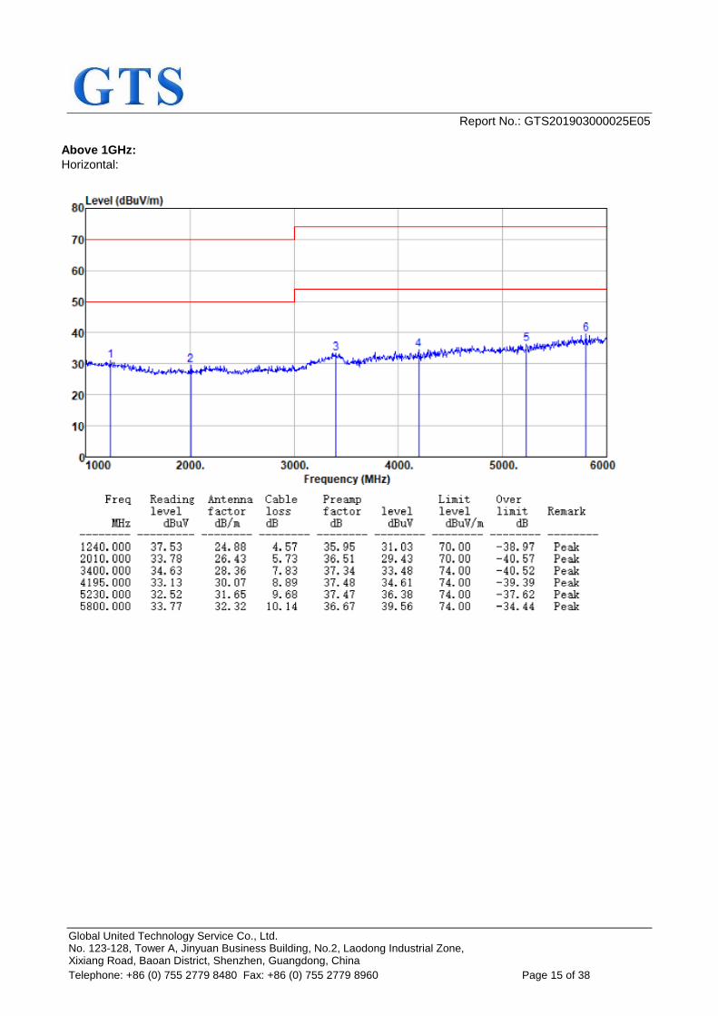
Above 1GHz:
Horizontal:
Report No.: GTS201903000025E05
Global United Technology Service Co., Ltd. No. 123-128, Tower A, Jinyuan Business Building, No.2, Laodong Industrial Zone, Xixiang Road, Baoan District, Shenzhen, Guangdong, China
Telephone: +86 (0) 755 2779 8480 Fax: +86 (0) 755 2779 8960 Page 16 of 38
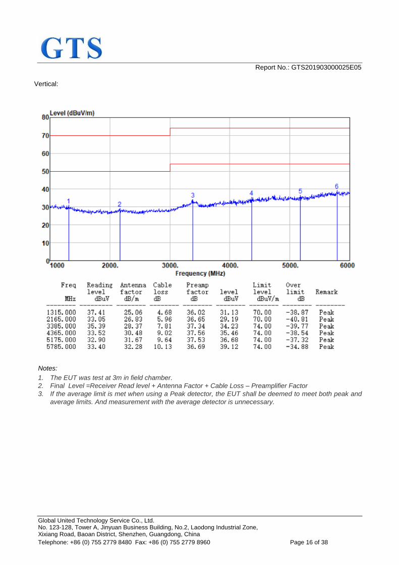
Vertical:
Notes:
1. The EUT was test at 3m in field chamber.
2. Final Level =Receiver Read level + Antenna Factor + Cable Loss – Preamplifier Factor
3. If the average limit is met when using a Peak detector, the EUT shall be deemed to meet both peak and
average limits. And measurement with the average detector is unnecessary.
Report No.: GTS201903000025E05
Global United Technology Service Co., Ltd. No. 123-128, Tower A, Jinyuan Business Building, No.2, Laodong Industrial Zone, Xixiang Road, Baoan District, Shenzhen, Guangdong, China
Telephone: +86 (0) 755 2779 8480 Fax: +86 (0) 755 2779 8960 Page 17 of 38
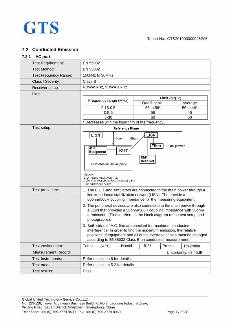
7.2 Conducted Emission
7.2.1 AC port
Test Requirement: EN 55032
Test Method: EN 55032
Test Frequency Range: 150kHz to 30MHz
Class / Severity: Class B Class B
Receiver setup: RBW=9kHz, VBW=30kHz
Limit:
Frequency range (MHz) Limit (dBµV)
Quasi-peak Average
0.15-0.5 66 to 56* 56 to 46*
0.5-5 56 46
5-30 60 50
* Decreases with the logarithm of the frequency.
Test setup:
Test procedure: 1. The E.U.T and simulators are connected to the main power through a
line impedance stabilization network(LISN). The provide a
50ohm/50uH coupling impedance for the measuring equipment.
2. The peripheral devices are also connected to the main power through
a LISN that provides a 50ohm/50uH coupling impedance with 50ohm
termination. (Please refers to the block diagram of the test setup and
photographs).
3. Both sides of A.C. line are checked for maximum conducted
interference. In order to find the maximum emission, the relative
positions of equipment and all of the interface cables must be changed
according to EN55032 Class B on conducted measurement.
Test environment: Temp.: 24 C Humid.: 51% Press.: 1012mbar
Measurement Record: Uncertainty: 3.45dB
Test Instruments: Refer to section 6 for details
Test mode: Refer to section 5.2 for details
Test results: Pass
Report No.: GTS201903000025E05
Global United Technology Service Co., Ltd. No. 123-128, Tower A, Jinyuan Business Building, No.2, Laodong Industrial Zone, Xixiang Road, Baoan District, Shenzhen, Guangdong, China
Telephone: +86 (0) 755 2779 8480 Fax: +86 (0) 755 2779 8960 Page 18 of 38
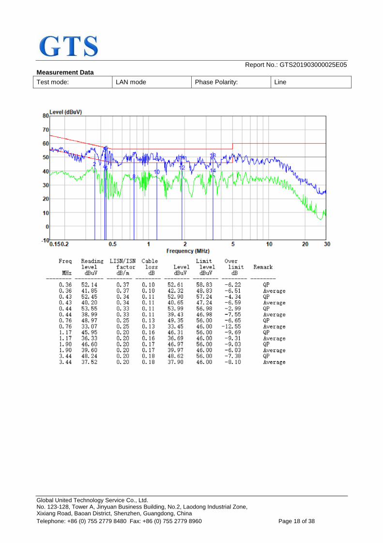
Measurement Data
Test mode: LAN mode Phase Polarity: Line
Report No.: GTS201903000025E05
Global United Technology Service Co., Ltd. No. 123-128, Tower A, Jinyuan Business Building, No.2, Laodong Industrial Zone, Xixiang Road, Baoan District, Shenzhen, Guangdong, China
Telephone: +86 (0) 755 2779 8480 Fax: +86 (0) 755 2779 8960 Page 19 of 38
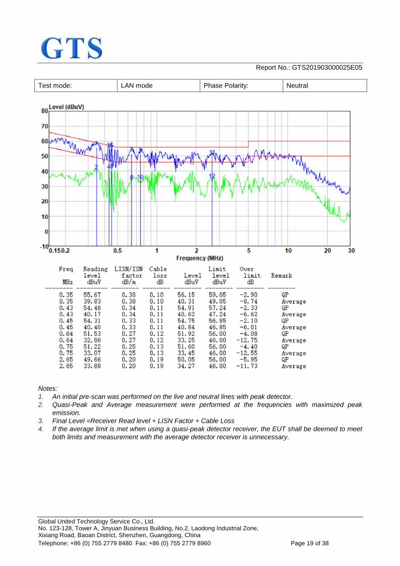
Test mode: LAN mode Phase Polarity: Neutral
Notes:
1. An initial pre-scan was performed on the live and neutral lines with peak detector.
2. Quasi-Peak and Average measurement were performed at the frequencies with maximized peak
emission.
3. Final Level =Receiver Read level + LISN Factor + Cable Loss
4. If the average limit is met when using a quasi-peak detector receiver, the EUT shall be deemed to meet
both limits and measurement with the average detector receiver is unnecessary.
Report No.: GTS201903000025E05
Global United Technology Service Co., Ltd. No. 123-128, Tower A, Jinyuan Business Building, No.2, Laodong Industrial Zone, Xixiang Road, Baoan District, Shenzhen, Guangdong, China
Telephone: +86 (0) 755 2779 8480 Fax: +86 (0) 755 2779 8960 Page 20 of 38
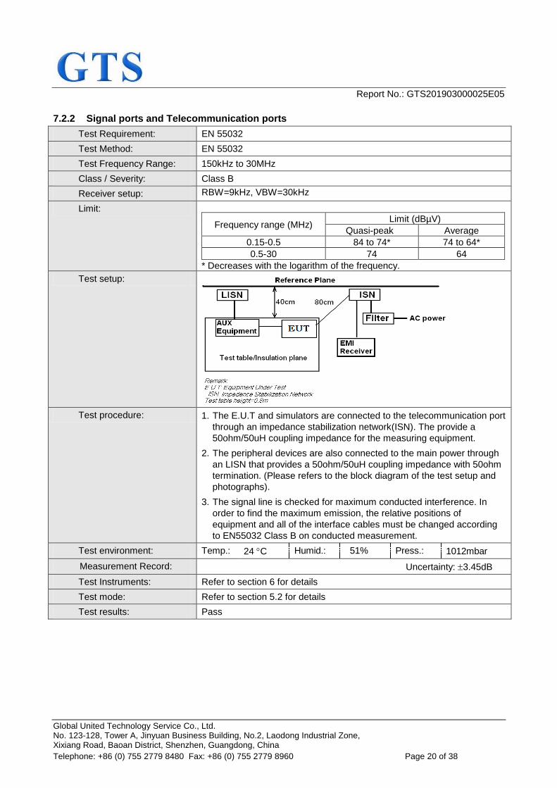
7.2.2 Signal ports and Telecommunication ports
Test Requirement: EN 55032
Test Method: EN 55032
Test Frequency Range: 150kHz to 30MHz
Class / Severity: Class B Class B
Receiver setup: RBW=9kHz, VBW=30kHz
Limit:
Frequency range (MHz) Limit (dBµV)
Quasi-peak Average
0.15-0.5 84 to 74* 74 to 64*
0.5-30 74 64
* Decreases with the logarithm of the frequency.
Test setup:
Test procedure: 1. The E.U.T and simulators are connected to the telecommunication port
through an impedance stabilization network(ISN). The provide a
50ohm/50uH coupling impedance for the measuring equipment.
2. The peripheral devices are also connected to the main power through
an LISN that provides a 50ohm/50uH coupling impedance with 50ohm
termination. (Please refers to the block diagram of the test setup and
photographs).
3. The signal line is checked for maximum conducted interference. In
order to find the maximum emission, the relative positions of
equipment and all of the interface cables must be changed according
to EN55032 Class B on conducted measurement.
Test environment: Temp.: 24 C Humid.: 51% Press.: 1012mbar
Measurement Record: Uncertainty: 3.45dB
Test Instruments: Refer to section 6 for details
Test mode: Refer to section 5.2 for details
Test results: Pass
Report No.: GTS201903000025E05
Global United Technology Service Co., Ltd. No. 123-128, Tower A, Jinyuan Business Building, No.2, Laodong Industrial Zone, Xixiang Road, Baoan District, Shenzhen, Guangdong, China
Telephone: +86 (0) 755 2779 8480 Fax: +86 (0) 755 2779 8960 Page 21 of 38
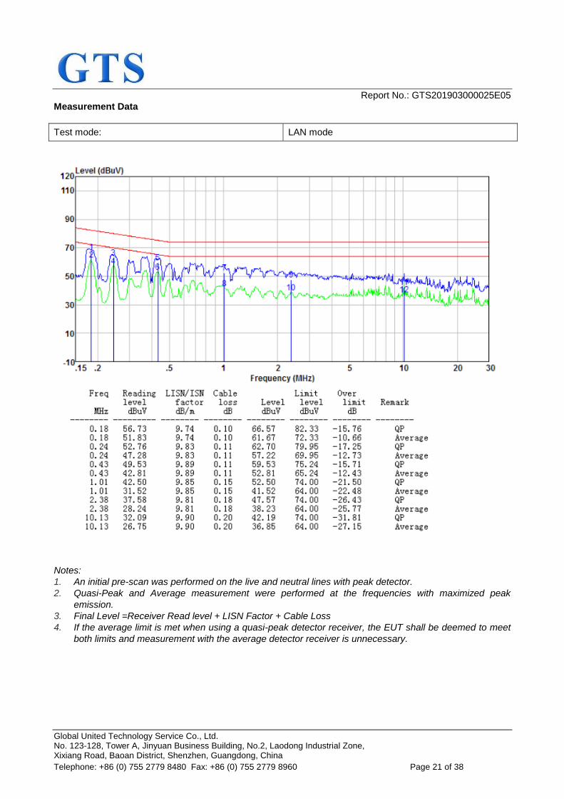
Measurement Data
Test mode: LAN mode
Notes:
1. An initial pre-scan was performed on the live and neutral lines with peak detector.
2. Quasi-Peak and Average measurement were performed at the frequencies with maximized peak
emission.
3. Final Level =Receiver Read level + LISN Factor + Cable Loss
4. If the average limit is met when using a quasi-peak detector receiver, the EUT shall be deemed to meet
both limits and measurement with the average detector receiver is unnecessary.
Report No.: GTS201903000025E05
Global United Technology Service Co., Ltd. No. 123-128, Tower A, Jinyuan Business Building, No.2, Laodong Industrial Zone, Xixiang Road, Baoan District, Shenzhen, Guangdong, China
Telephone: +86 (0) 755 2779 8480 Fax: +86 (0) 755 2779 8960 Page 22 of 38
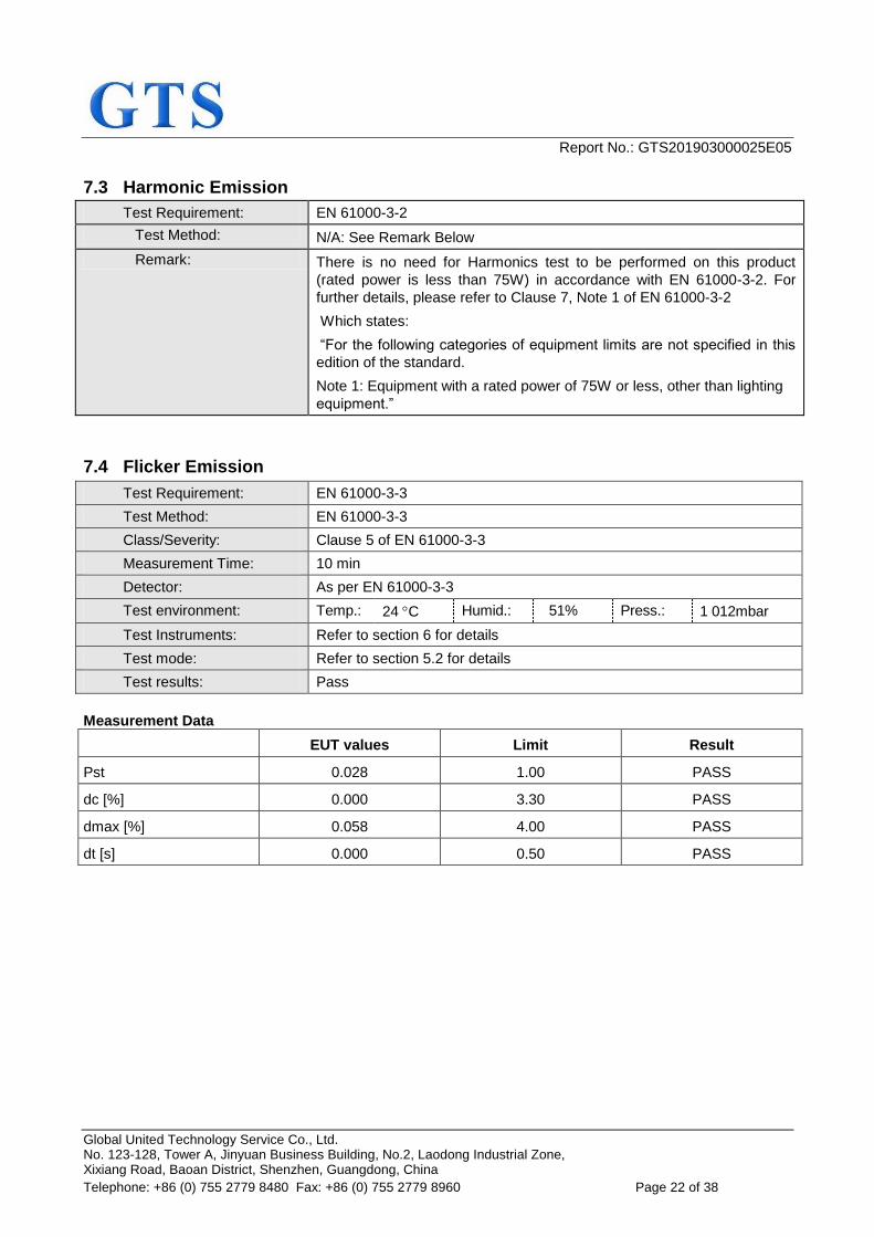
7.3 Harmonic Emission
Test Requirement: EN 61000-3-2
Test Method: N/A: See Remark Below
Remark: There is no need for Harmonics test to be performed on this product
(rated power is less than 75W) in accordance with EN 61000-3-2. For
further details, please refer to Clause 7, Note 1 of EN 61000-3-2
Which states:
“For the following categories of equipment limits are not specified in this
edition of the standard.
Note 1: Equipment with a rated power of 75W or less, other than lighting
equipment.”
7.4 Flicker Emission
Test Requirement: EN 61000-3-3
Test Method: EN 61000-3-3
Class/Severity: Clause 5 of EN 61000-3-3
Measurement Time: 10 min
Detector: As per EN 61000-3-3
Test environment: Temp.: 24 C Humid.: 51% Press.: 1 012mbar
Test Instruments: Refer to section 6 for details
Test mode: Refer to section 5.2 for details
Test results: Pass
Measurement Data
EUT values Limit Result
Pst 0.028 1.00 PASS
dc [%] 0.000 3.30 PASS
dmax [%] 0.058 4.00 PASS
dt [s] 0.000 0.50 PASS
Report No.: GTS201903000025E05
Global United Technology Service Co., Ltd. No. 123-128, Tower A, Jinyuan Business Building, No.2, Laodong Industrial Zone, Xixiang Road, Baoan District, Shenzhen, Guangdong, China
Telephone: +86 (0) 755 2779 8480 Fax: +86 (0) 755 2779 8960 Page 23 of 38
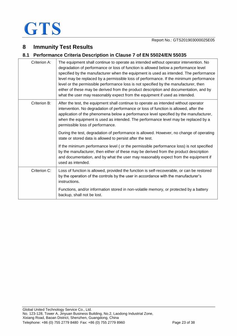
8 Immunity Test Results
8.1 Performance Criteria Description in Clause 7 of EN 55024/EN 55035
Criterion A: The equipment shall continue to operate as intended without operator intervention. No
degradation of performance or loss of function is allowed below a performance level
specified by the manufacturer when the equipment is used as intended. The performance
level may be replaced by a permissible loss of performance. If the minimum performance
level or the permissible performance loss is not specified by the manufacturer, then
either of these may be derived from the product description and documentation, and by
what the user may reasonably expect from the equipment if used as intended.
Criterion B: After the test, the equipment shall continue to operate as intended without operator
intervention. No degradation of performance or loss of function is allowed, after the
application of the phenomena below a performance level specified by the manufacturer,
when the equipment is used as intended. The performance level may be replaced by a
permissible loss of performance.
During the test, degradation of performance is allowed. However, no change of operating
state or stored data is allowed to persist after the test.
If the minimum performance level ( or the permissible performance loss) is not specified
by the manufacturer, then either of these may be derived from the product description
and documentation, and by what the user may reasonably expect from the equipment if
used as intended.
Criterion C: Loss of function is allowed, provided the function is self-recoverable, or can be restored
by the operation of the controls by the user in accordance with the manufacturer’s
instructions.
Functions, and/or information stored in non-volatile memory, or protected by a battery
backup, shall not be lost.
Report No.: GTS201903000025E05
Global United Technology Service Co., Ltd. No. 123-128, Tower A, Jinyuan Business Building, No.2, Laodong Industrial Zone, Xixiang Road, Baoan District, Shenzhen, Guangdong, China
Telephone: +86 (0) 755 2779 8480 Fax: +86 (0) 755 2779 8960 Page 24 of 38
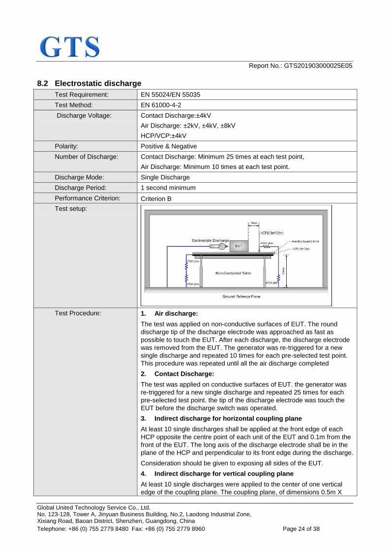
8.2 Electrostatic discharge
Test Requirement: EN 55024/EN 55035
Test Method: EN 61000-4-2
Discharge Voltage: Contact Discharge:±4kV
Air Discharge: ±2kV, ±4kV, ±8kV
HCP/VCP:±4kV
Polarity: Positive & Negative
Number of Discharge: Contact Discharge: Minimum 25 times at each test point,
Air Discharge: Minimum 10 times at each test point.
Discharge Mode: Single Discharge
Discharge Period: 1 second minimum
Performance Criterion: Criterion B
Test setup:
Test Procedure: 1. Air discharge:
The test was applied on non-conductive surfaces of EUT. The round
discharge tip of the discharge electrode was approached as fast as
possible to touch the EUT. After each discharge, the discharge electrode
was removed from the EUT. The generator was re-triggered for a new
single discharge and repeated 10 times for each pre-selected test point.
This procedure was repeated until all the air discharge completed
2. Contact Discharge:
The test was applied on conductive surfaces of EUT. the generator was
re-triggered for a new single discharge and repeated 25 times for each
pre-selected test point. the tip of the discharge electrode was touch the
EUT before the discharge switch was operated.
3. Indirect discharge for horizontal coupling plane
At least 10 single discharges shall be applied at the front edge of each
HCP opposite the centre point of each unit of the EUT and 0.1m from the
front of the EUT. The long axis of the discharge electrode shall be in the
plane of the HCP and perpendicular to its front edge during the discharge.
Consideration should be given to exposing all sides of the EUT.
4. Indirect discharge for vertical coupling plane
At least 10 single discharges were applied to the center of one vertical
edge of the coupling plane. The coupling plane, of dimensions 0.5m X
Report No.: GTS201903000025E05
Global United Technology Service Co., Ltd. No. 123-128, Tower A, Jinyuan Business Building, No.2, Laodong Industrial Zone, Xixiang Road, Baoan District, Shenzhen, Guangdong, China
Telephone: +86 (0) 755 2779 8480 Fax: +86 (0) 755 2779 8960 Page 25 of 38
0.5m, was placed parallel to, and positioned at a distance of 0.1m from
the EUT. Discharges were applied to the coupling plane, with this plane in
sufficient different positions that the four faces of the EUT are completely
illuminated.
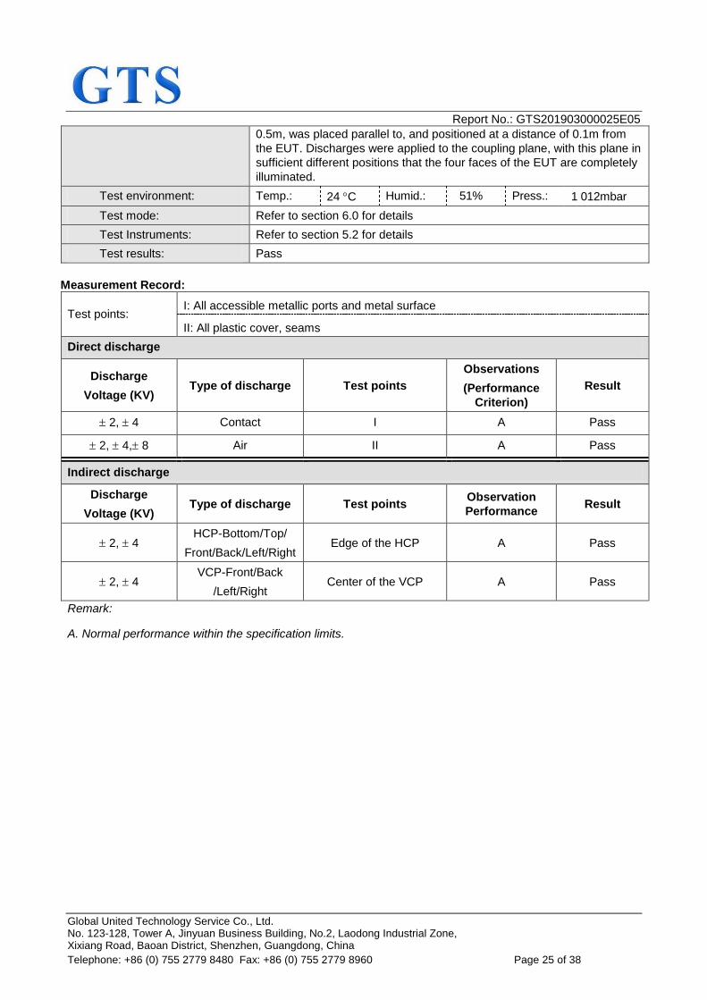
Test environment: Temp.: 24 C Humid.: 51% Press.: 1 012mbar
Test mode: Refer to section 6.0 for details
Test Instruments: Refer to section 5.2 for details
Test results: Pass
Measurement Record:
Test points: I: All accessible metallic ports and metal surface
II: All plastic cover, seams
Direct discharge
Discharge
Voltage (KV) Type of discharge Test points
Observations
(Performance
Criterion)
Result
2, 4 Contact I A Pass
2, 4, 8 Air II A Pass
Indirect discharge
Discharge
Voltage (KV) Type of discharge Test points
Observation
Performance Result
2, 4 HCP-Bottom/Top/
Front/Back/Left/Right Edge of the HCP A Pass
2, 4 VCP-Front/Back
/Left/Right Center of the VCP A Pass
Remark:
A. Normal performance within the specification limits.
Report No.: GTS201903000025E05
Global United Technology Service Co., Ltd. No. 123-128, Tower A, Jinyuan Business Building, No.2, Laodong Industrial Zone, Xixiang Road, Baoan District, Shenzhen, Guangdong, China
Telephone: +86 (0) 755 2779 8480 Fax: +86 (0) 755 2779 8960 Page 26 of 38
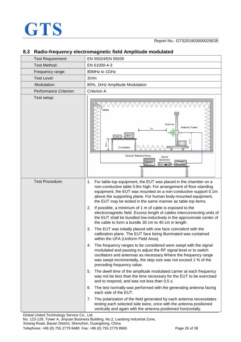
8.3 Radio-frequency electromagnetic field Amplitude modulated
Test Requirement: EN 55024/EN 55035
Test Method: EN 61000-4-3
Frequency range: 80MHz to 1GHz
Test Level: 3V/m
Modulation: 80%, 1kHz Amplitude Modulation
Performance Criterion: Criterion A
Test setup:
Test Procedure: 1. For table-top equipment, the EUT was placed in the chamber on a
non-conductive table 0.8m high. For arrangement of floor-standing
equipment, the EUT was mounted on a non-conductive support 0.1m
above the supporting plane. For human body-mounted equipment,
the EUT may be tested in the same manner as table top items.
2. If possible, a minimum of 1 m of cable is exposed to the
electromagnetic field. Excess length of cables interconnecting units of
the EUT shall be bundled low-inductively in the approximate center of
the cable to form a bundle 30 cm to 40 cm in length.
3. The EUT was initially placed with one face coincident with the
calibration plane. The EUT face being illuminated was contained
within the UFA (Uniform Field Area).
4. The frequency ranges to be considered were swept with the signal
modulated and pausing to adjust the RF signal level or to switch
oscillators and antennas as necessary.Where the frequency range
was swept incrementally, the step size was not exceed 1 % of the
preceding frequency value.
5. The dwell time of the amplitude modulated carrier at each frequency
was not be less than the time necessary for the EUT to be exercised
and to respond, and was not less than 0,5 s.
6. The test normally was performed with the generating antenna facing
each side of the EUT.
7. The polarization of the field generated by each antenna necessitates
testing each selected side twice, once with the antenna positioned
vertically and again with the antenna positioned horizontally.
Report No.: GTS201903000025E05
Global United Technology Service Co., Ltd. No. 123-128, Tower A, Jinyuan Business Building, No.2, Laodong Industrial Zone, Xixiang Road, Baoan District, Shenzhen, Guangdong, China
Telephone: +86 (0) 755 2779 8480 Fax: +86 (0) 755 2779 8960 Page 27 of 38
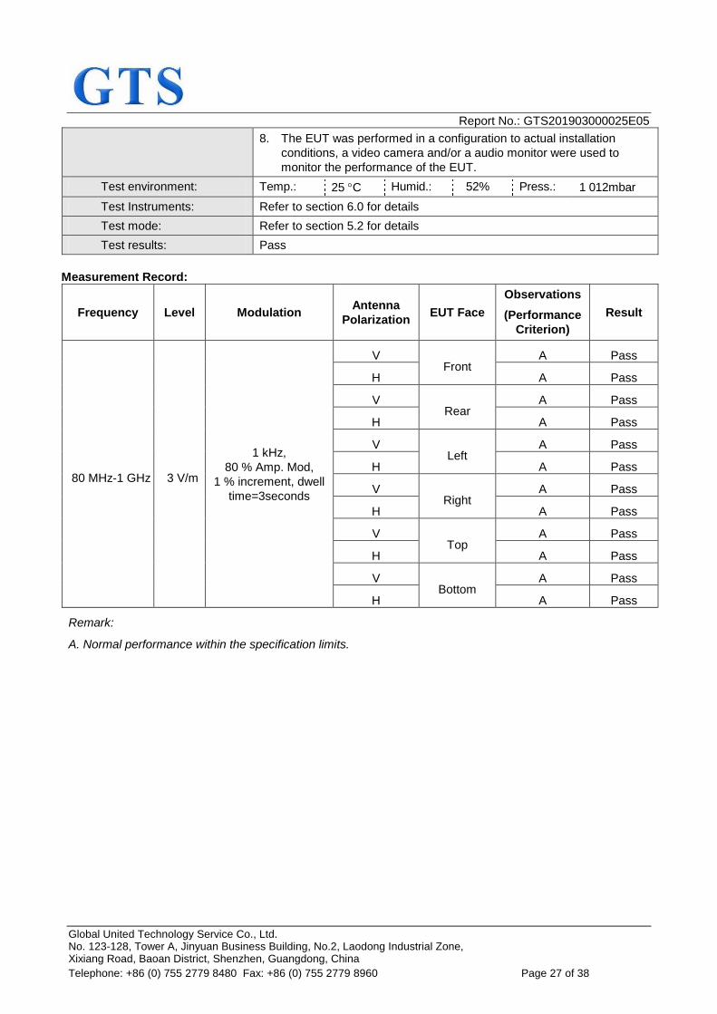
8. The EUT was performed in a configuration to actual installation
conditions, a video camera and/or a audio monitor were used to
monitor the performance of the EUT.
Test environment: Temp.: 25 C Humid.: 52% Press.: 1 012mbar
Test Instruments: Refer to section 6.0 for details
Test mode: Refer to section 5.2 for details
Test results: Pass
Measurement Record:
Frequency Level Modulation Antenna
Polarization EUT Face
Observations
(Performance
Criterion)
Result
80 MHz-1 GHz 3 V/m
1 kHz,
80 % Amp. Mod,
1 % increment, dwell
time=3seconds
V Front
A Pass
H A Pass
V Rear
A Pass
H A Pass
V Left
A Pass
H A Pass
V Right
A Pass
H A Pass
V Top
A Pass
H A Pass
V Bottom
A Pass
H A Pass
Remark:
A. Normal performance within the specification limits.
Report No.: GTS201903000025E05
Global United Technology Service Co., Ltd. No. 123-128, Tower A, Jinyuan Business Building, No.2, Laodong Industrial Zone, Xixiang Road, Baoan District, Shenzhen, Guangdong, China
Telephone: +86 (0) 755 2779 8480 Fax: +86 (0) 755 2779 8960 Page 28 of 38
8.4 Electrical fast transients
8.4.1 AC port
Test Requirement: EN 55024/EN 55035
Test Method: EN 61000-4-4
Test Level: 1.0kV
Polarity: Positive & Negative
Test signal specification: Rise time=5ns, Duration time=50ns;
Burst Duration=15ms, Burst Period=300ms;
Repetition Frequency=5KHz
Test Duration: 2 minute per level & polarity
Performance Criterion: Criterion B
Test setup:
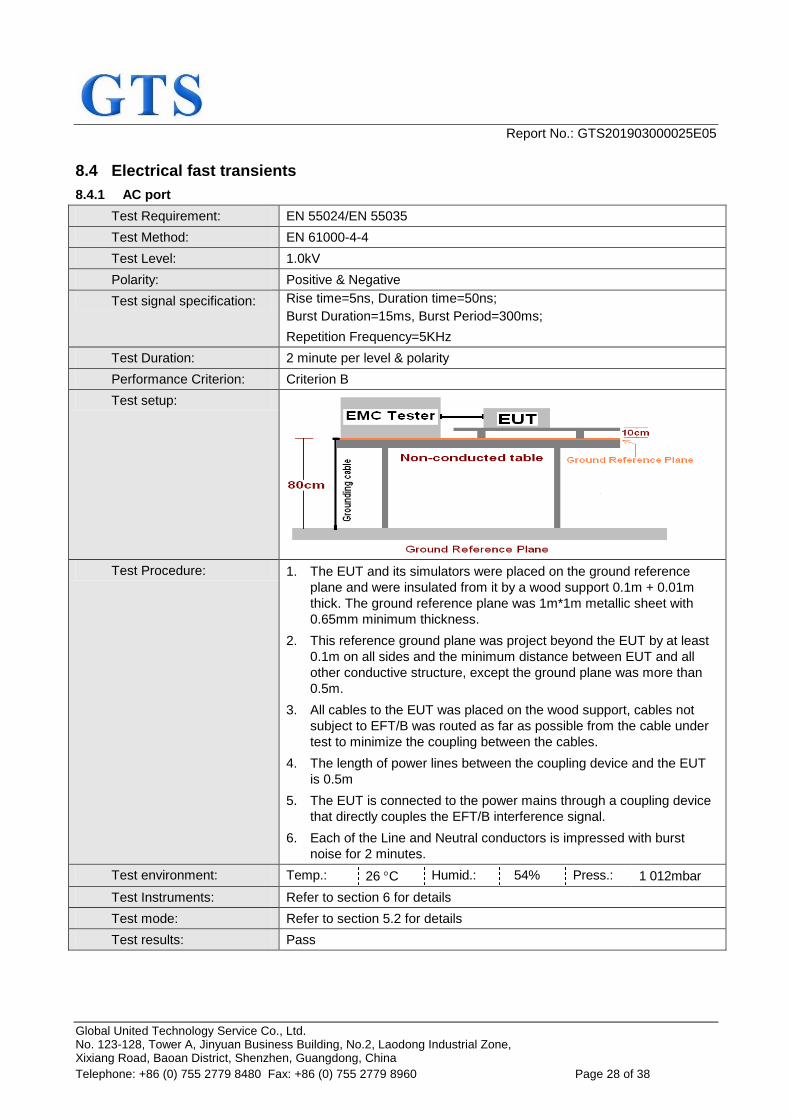
Test Procedure: 1. The EUT and its simulators were placed on the ground reference
plane and were insulated from it by a wood support 0.1m + 0.01m
thick. The ground reference plane was 1m*1m metallic sheet with
0.65mm minimum thickness.
2. This reference ground plane was project beyond the EUT by at least
0.1m on all sides and the minimum distance between EUT and all
other conductive structure, except the ground plane was more than
0.5m.
3. All cables to the EUT was placed on the wood support, cables not
subject to EFT/B was routed as far as possible from the cable under
test to minimize the coupling between the cables.
4. The length of power lines between the coupling device and the EUT
is 0.5m
5. The EUT is connected to the power mains through a coupling device
that directly couples the EFT/B interference signal.
6. Each of the Line and Neutral conductors is impressed with burst
noise for 2 minutes.
Test environment: Temp.: 26 C Humid.: 54% Press.: 1 012mbar
Test Instruments: Refer to section 6 for details
Test mode: Refer to section 5.2 for details
Test results: Pass
Report No.: GTS201903000025E05
Global United Technology Service Co., Ltd. No. 123-128, Tower A, Jinyuan Business Building, No.2, Laodong Industrial Zone, Xixiang Road, Baoan District, Shenzhen, Guangdong, China
Telephone: +86 (0) 755 2779 8480 Fax: +86 (0) 755 2779 8960 Page 29 of 38
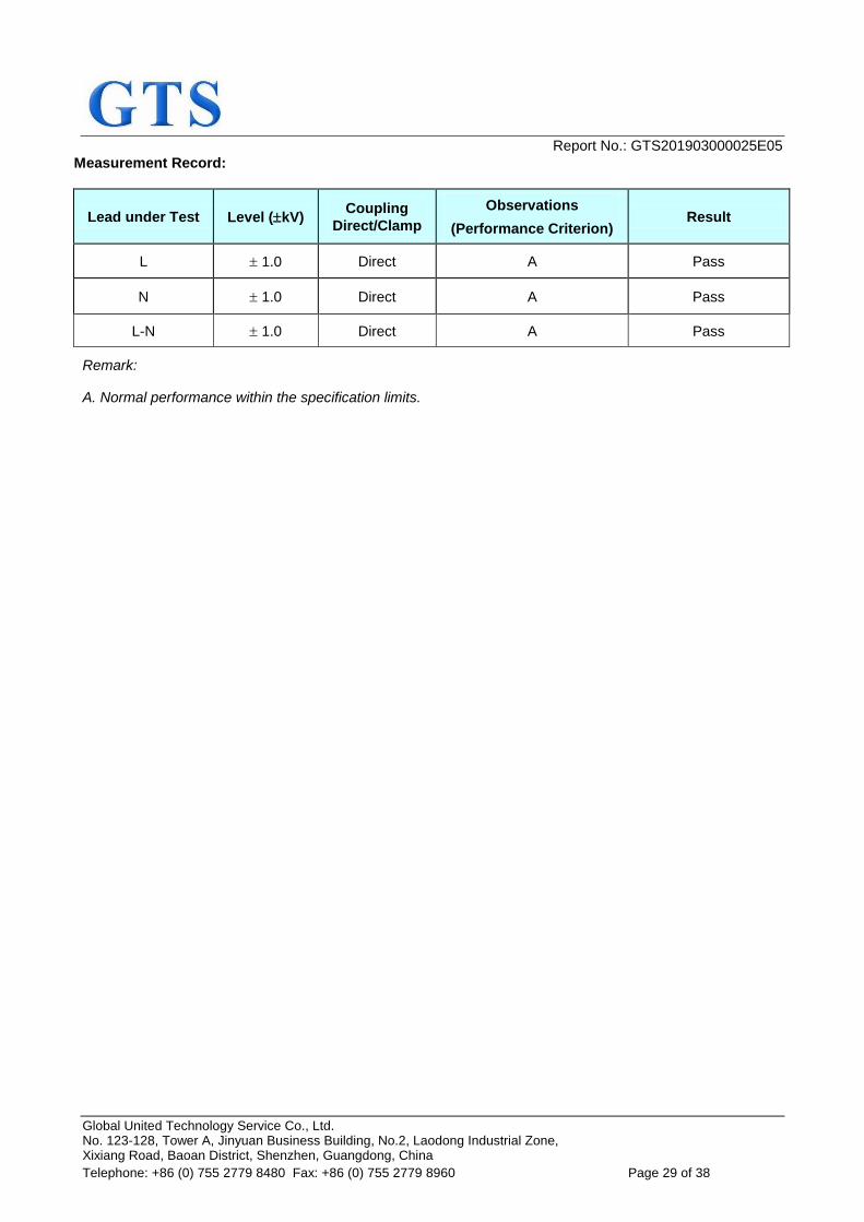
Measurement Record:
Lead under Test Level (kV) Coupling
Direct/Clamp
Observations
(Performance Criterion) Result
L 1.0 Direct A Pass
N 1.0 Direct A Pass
L-N 1.0 Direct A Pass
Remark:
A. Normal performance within the specification limits.
Report No.: GTS201903000025E05
Global United Technology Service Co., Ltd. No. 123-128, Tower A, Jinyuan Business Building, No.2, Laodong Industrial Zone, Xixiang Road, Baoan District, Shenzhen, Guangdong, China
Telephone: +86 (0) 755 2779 8480 Fax: +86 (0) 755 2779 8960 Page 30 of 38
8.4.2 Signal ports and Telecommunication ports
Test Requirement: EN 55024/EN 55035
Test Method: EN 61000-4-4
Test Level: 0.5KV
Polarity: Positive & Negative
Test signal specification: Rise time=5ns, Duration time=50ns;
Burst Duration=15ms, Burst Period=300ms;
Repetition Frequency=5KHz
Test Duration: 2 minute per level & polarity
Performance Criterion: Criterion B
Test setup:
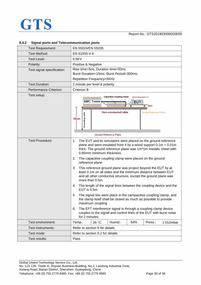
Test Procedure: 1. The EUT and its simulators were placed on the ground reference
plane and were insulated from it by a wood support 0.1m + 0.01m
thick. The ground reference plane was 1m*1m metallic sheet with
0.65mm minimum thickness.
2. The capacitive coupling clamp were placed on the ground
reference plane.
3. This reference ground plane was project beyond the EUT by at
least 0.1m on all sides and the minimum distance between EUT
and all other conductive structure, except the ground plane was
more than 0.5m.
4. The length of the signal lines between the coupling device and the
EUT is 0.5m
5. The signal line were place in the campacitive coupling clamp, and
the clamp itself shall be closed as much as possible to provide
maximum coupling
6. The EFT interference signal is through a coupling clamp device
couples to the signal and control lines of the EUT with burst noise
for 2 minutes.
Test environment: Temp.: 26 C Humid.: 54% Press.: 1 012mbar
Test Instruments: Refer to section 6 for details
Test mode: Refer to section 5.2 for details
Test results: Pass
Report No.: GTS201903000025E05
Global United Technology Service Co., Ltd. No. 123-128, Tower A, Jinyuan Business Building, No.2, Laodong Industrial Zone, Xixiang Road, Baoan District, Shenzhen, Guangdong, China
Telephone: +86 (0) 755 2779 8480 Fax: +86 (0) 755 2779 8960 Page 31 of 38
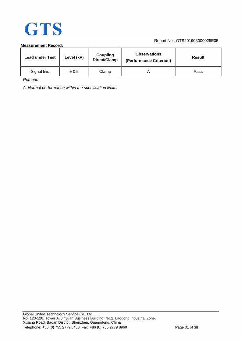
Measurement Record:
Lead under Test Level (kV) Coupling
Direct/Clamp
Observations
(Performance Criterion) Result
Signal line 0.5 Clamp A Pass
Remark:
A. Normal performance within the specification limits.
Report No.: GTS201903000025E05
Global United Technology Service Co., Ltd. No. 123-128, Tower A, Jinyuan Business Building, No.2, Laodong Industrial Zone, Xixiang Road, Baoan District, Shenzhen, Guangdong, China
Telephone: +86 (0) 755 2779 8480 Fax: +86 (0) 755 2779 8960 Page 32 of 38
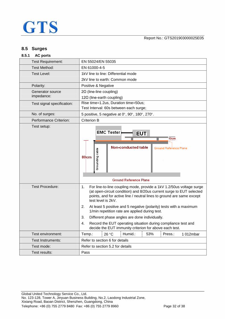
8.5 Surges
8.5.1 AC ports
Test Requirement: EN 55024/EN 55035
Test Method: EN 61000-4-5
Test Level: 1kV line to line: Differential mode
2kV line to earth: Common mode
Polarity: Positive & Negative
Generator source impedance:
2Ω (line-line coupling)
12Ω (line-earth coupling)
Test signal specification: Rise time=1.2us, Duration time=50us;
Test Interval: 60s between each surge;
No. of surges: 5 positive, 5 negative at 0, 90, 180, 270.
Performance Criterion: Criterion B
Test setup:
Test Procedure: 1. For line-to-line coupling mode, provide a 1kV 1.2/50us voltage surge
(at open-circuit condition) and 8/20us current surge to EUT selected
points, and for active line / neutral lines to ground are same except
test level is 2kV.
2. At least 5 positive and 5 negative (polarity) tests with a maximum
1/min repetition rate are applied during test.
3. Different phase angles are done individually.
4. Record the EUT operating situation during compliance test and
decide the EUT immunity criterion for above each test.
Test environment: Temp.: 26 C Humid.: 53% Press.: 1 012mbar
Test Instruments: Refer to section 6 for details
Test mode: Refer to section 5.2 for details
Test results: Pass
Report No.: GTS201903000025E05
Global United Technology Service Co., Ltd. No. 123-128, Tower A, Jinyuan Business Building, No.2, Laodong Industrial Zone, Xixiang Road, Baoan District, Shenzhen, Guangdong, China
Telephone: +86 (0) 755 2779 8480 Fax: +86 (0) 755 2779 8960 Page 33 of 38
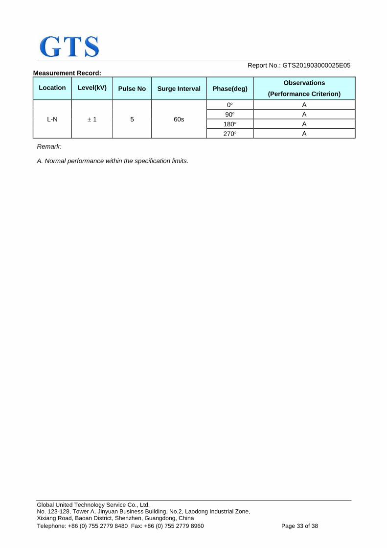
Measurement Record:
Location Level(kV) Pulse No Surge Interval Phase(deg) Observations
(Performance Criterion)
L-N 1 5 60s
0 A
90 A
180 A
270 A
Remark:
A. Normal performance within the specification limits.
Report No.: GTS201903000025E05
Global United Technology Service Co., Ltd. No. 123-128, Tower A, Jinyuan Business Building, No.2, Laodong Industrial Zone, Xixiang Road, Baoan District, Shenzhen, Guangdong, China
Telephone: +86 (0) 755 2779 8480 Fax: +86 (0) 755 2779 8960 Page 34 of 38
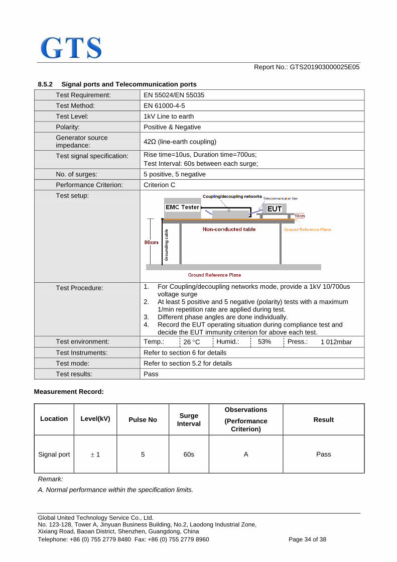
8.5.2 Signal ports and Telecommunication ports
Test Requirement: EN 55024/EN 55035
Test Method: EN 61000-4-5
Test Level: 1kV Line to earth
Polarity: Positive & Negative
Generator source impedance:
42Ω (line-earth coupling)
Test signal specification: Rise time=10us, Duration time=700us;
Test Interval: 60s between each surge;
No. of surges: 5 positive, 5 negative
Performance Criterion: Criterion C
Test setup:
Test Procedure: 1. For Coupling/decoupling networks mode, provide a 1kV 10/700us voltage surge
2. At least 5 positive and 5 negative (polarity) tests with a maximum 1/min repetition rate are applied during test.
3. Different phase angles are done individually. 4. Record the EUT operating situation during compliance test and
decide the EUT immunity criterion for above each test.
Test environment: Temp.: 26 C Humid.: 53% Press.: 1 012mbar
Test Instruments: Refer to section 6 for details
Test mode: Refer to section 5.2 for details
Test results: Pass
Measurement Record:
Location Level(kV) Pulse No Surge
Interval
Observations
(Performance
Criterion)
Result
Signal port 1 5 60s A Pass
Remark:
A. Normal performance within the specification limits.
Report No.: GTS201903000025E05
Global United Technology Service Co., Ltd. No. 123-128, Tower A, Jinyuan Business Building, No.2, Laodong Industrial Zone, Xixiang Road, Baoan District, Shenzhen, Guangdong, China
Telephone: +86 (0) 755 2779 8480 Fax: +86 (0) 755 2779 8960 Page 35 of 38
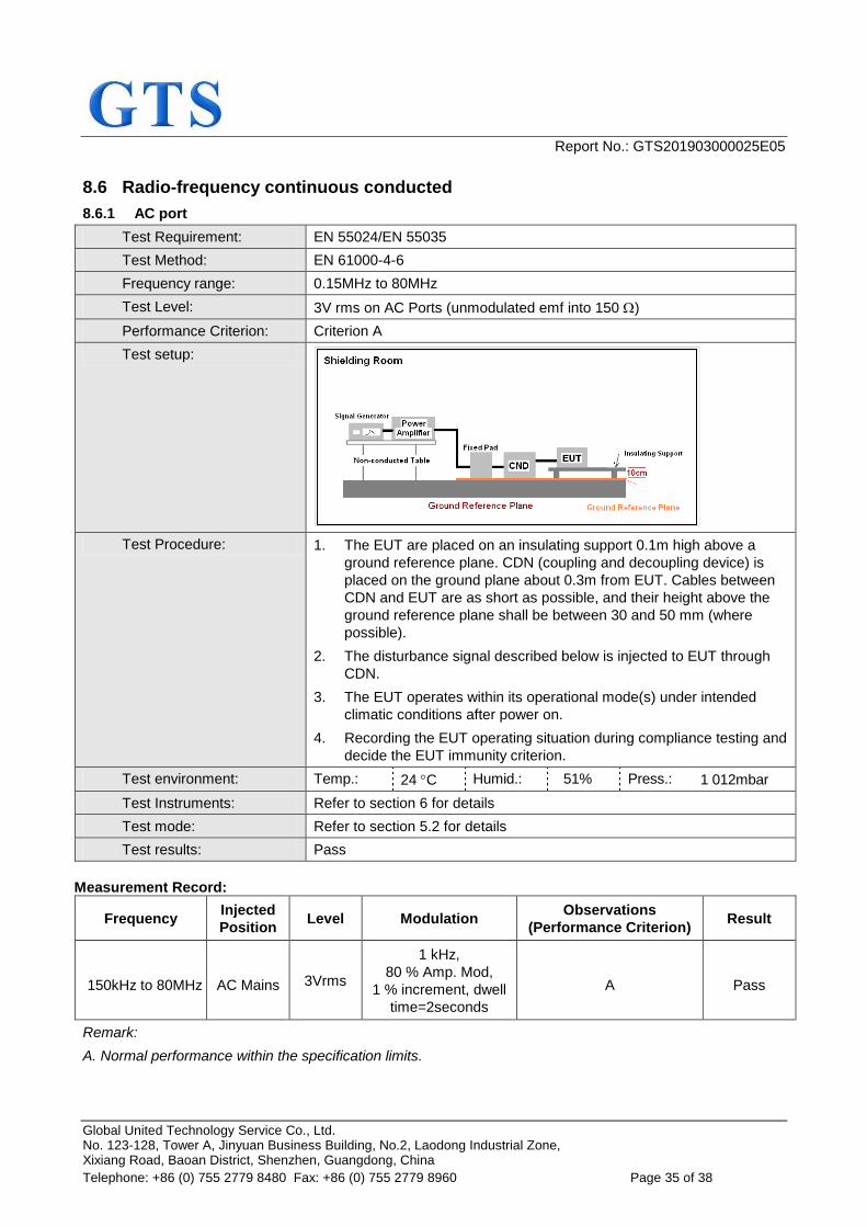
8.6 Radio-frequency continuous conducted
8.6.1 AC port
Test Requirement: EN 55024/EN 55035
Test Method: EN 61000-4-6
Frequency range: 0.15MHz to 80MHz
Test Level: 3V rms on AC Ports (unmodulated emf into 150 )
Performance Criterion: Criterion A
Test setup:
Test Procedure: 1. The EUT are placed on an insulating support 0.1m high above a
ground reference plane. CDN (coupling and decoupling device) is
placed on the ground plane about 0.3m from EUT. Cables between
CDN and EUT are as short as possible, and their height above the
ground reference plane shall be between 30 and 50 mm (where
possible).
2. The disturbance signal described below is injected to EUT through
CDN.
3. The EUT operates within its operational mode(s) under intended
climatic conditions after power on.
4. Recording the EUT operating situation during compliance testing and
decide the EUT immunity criterion.
Test environment: Temp.: 24 C Humid.: 51% Press.: 1 012mbar
Test Instruments: Refer to section 6 for details
Test mode: Refer to section 5.2 for details
Test results: Pass
Measurement Record:
Frequency Injected
Position Level Modulation
Observations
(Performance Criterion) Result
150kHz to 80MHz AC Mains 3Vrms
1 kHz,
80 % Amp. Mod,
1 % increment, dwell
time=2seconds
A Pass
Remark:
A. Normal performance within the specification limits.
Report No.: GTS201903000025E05
Global United Technology Service Co., Ltd. No. 123-128, Tower A, Jinyuan Business Building, No.2, Laodong Industrial Zone, Xixiang Road, Baoan District, Shenzhen, Guangdong, China
Telephone: +86 (0) 755 2779 8480 Fax: +86 (0) 755 2779 8960 Page 36 of 38
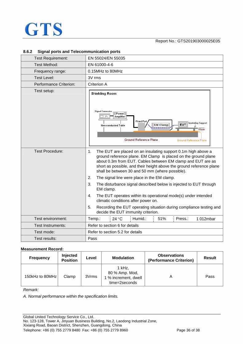
8.6.2 Signal ports and Telecommunication ports
Test Requirement: EN 55024/EN 55035
Test Method: EN 61000-4-6
Frequency range: 0.15MHz to 80MHz
Test Level: 3V rms
Performance Criterion: Criterion A
Test setup:
Test Procedure: 1. The EUT are placed on an insulating support 0.1m high above a
ground reference plane. EM Clamp is placed on the ground plane
about 0.3m from EUT. Cables between EM clamp and EUT are as
short as possible, and their height above the ground reference plane
shall be between 30 and 50 mm (where possible).
2. The signal line were place in the EM clamp.
3. The disturbance signal described below is injected to EUT through
EM clamp.
4. The EUT operates within its operational mode(s) under intended
climatic conditions after power on.
5. Recording the EUT operating situation during compliance testing and
decide the EUT immunity criterion.
Test environment: Temp.: 24 C Humid.: 51% Press.: 1 012mbar
Test Instruments: Refer to section 6 for details
Test mode: Refer to section 5.2 for details
Test results: Pass
Measurement Record:
Frequency Injected
Position Level Modulation
Observations
(Performance Criterion) Result
150kHz to 80MHz Clamp 3Vrms
1 kHz,
80 % Amp. Mod,
1 % increment, dwell
time=2seconds
A Pass
Remark:
A. Normal performance within the specification limits.
Report No.: GTS201903000025E05
Global United Technology Service Co., Ltd. No. 123-128, Tower A, Jinyuan Business Building, No.2, Laodong Industrial Zone, Xixiang Road, Baoan District, Shenzhen, Guangdong, China
Telephone: +86 (0) 755 2779 8480 Fax: +86 (0) 755 2779 8960 Page 37 of 38
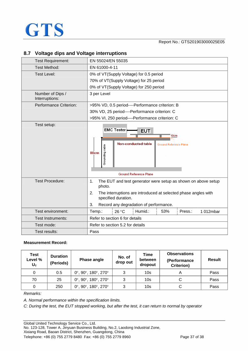
8.7 Voltage dips and Voltage interruptions
Test Requirement: EN 55024/EN 55035
Test Method: EN 61000-4-11
Test Level: 0% of VT(Supply Voltage) for 0.5 period
70% of VT(Supply Voltage) for 25 period
0% of VT(Supply Voltage) for 250 period
Number of Dips / Interruptions:
3 per Level
Performance Criterion: >95% VD, 0.5 period----Performance criterion: B
30% VD, 25 period----Performance criterion: C
>95% VI, 250 period----Performance criterion: C
Test setup:
Test Procedure: 1. The EUT and test generator were setup as shown on above setup
photo.
2. The interruptions are introduced at selected phase angles with
specified duration.
3. Record any degradation of performance.
Test environment: Temp.: 26 C Humid.: 53% Press.: 1 012mbar
Test Instruments: Refer to section 6 for details
Test mode: Refer to section 5.2 for details
Test results: Pass
Measurement Record:
Test
Level %
UT
Duration
(Periods) Phase angle
No. of
drop out
Time
between
dropout
Observations
(Performance
Criterion)
Result
0 0.5 0, 90, 180, 270 3 10s A Pass
70 25 0, 90, 180, 270 3 10s C Pass
0 250 0, 90, 180, 270 3 10s C Pass
Remarks:
A. Normal performance within the specification limits.
C: During the test, the EUT stopped working, but after the test, it can return to normal by operator
Report No.: GTS201903000025E05
Global United Technology Service Co., Ltd. No. 123-128, Tower A, Jinyuan Business Building, No.2, Laodong Industrial Zone, Xixiang Road, Baoan District, Shenzhen, Guangdong, China
Telephone: +86 (0) 755 2779 8480 Fax: +86 (0) 755 2779 8960 Page 38 of 38
9 Test Setup Photo Reference to the appendix I for details.
10 EUT Constructional Details Reference to the appendix II for details.
------End------