Embed Size (px)
DESCRIPTION
Report Final - Upsetting of engine valves and parametric study on engine valves
Citation preview
1
TABLE OF CONTENTS
TITLE PAGE No.
BONAFIDE CERTIFICATE
ABSTRACT
ACKNOWLEDGEMENTS
LIST OF SYMBOLS AND ABBREVATIONS
INTRODUCTION
Engine Valves and it’s function 1
Types of Engine Valve and 2
Valve materials 3
METAL FORMING PROCESS
Metal working and it’s types 5
Types of forging process
Impact forging 6
Drop forging 7
Upset forging 8
Engine valve manufacturing process 15
2
TITLE PAGE No.
LITERATURE SURVEY
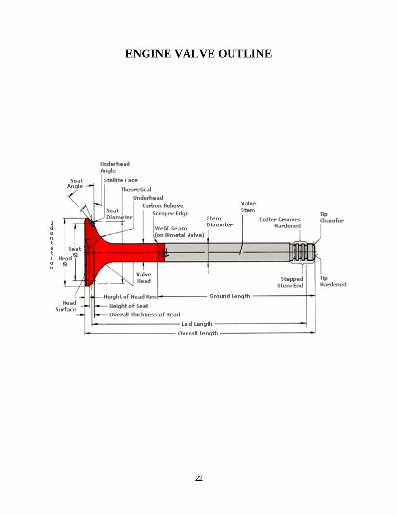
ENGINE VALVE OUTLINE 20
UPSETTING PROCESS AND
IT’S PARAMETRIC STUDY ON ENGINE VALVES
Objective of the project 21
Project plan 24
Data collected 26
Correlation of data’s 32
Data Sheetn 39
Advantages 41
CONCLUTION 42
REFERENCES
3
INTRODUCTION
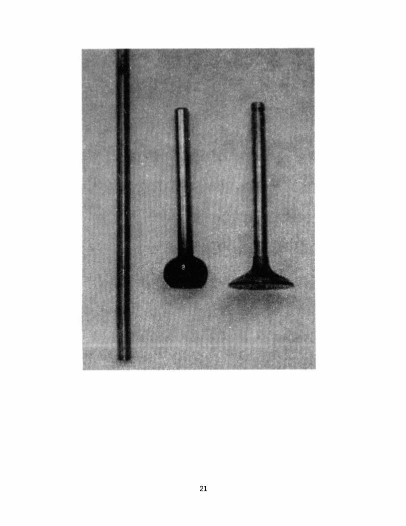
ENGINE VALVES
An engine valve is a very important part of your engine running. It is in the head which is just over the block and pistons. There are exhaust and intake valves. The camshaft triggers the valves to go up at certain point to allow air and fuel in for intake and allow waste to get out through exhaust. they return down with a spring and seal up the combustion chamber give you the compression needed for the engine to run and the fuel to ignite and drive the pistons. timing is everything when it comes to valves or basically anything in an engine.
Engine valves are located in the cylinder head. The main function of the engine valves is to let air in and out of the cylinders. That air is used to help ignite the fuel which will drive the pistons up and down.
There are two types of engine valves; intake and exhaust valves.
The intake valves of course let air in, and the exhaust valves let exhaust air out. The more air you can move air in and out of the engine the more efficient, and therefore power the engine will have. The Inlet valves are typically made of SUH-11,SUH-38 (Martensite materials) and the Exhaust valves are made of 21-4N, 23-8N(Austenite materials) for many performance applications. This is why the engine valve plays a pretty critical role in an engines performance.
4
TYPES OF VALVES
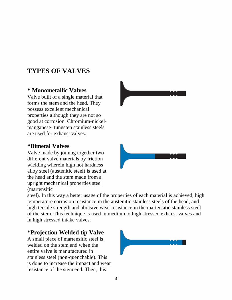
* Monometallic Valves Valve built of a single material that forms the stem and the head. They possess excellent mechanical properties although they are not so good at corrosion. Chromium-nickel-manganese- tungsten stainless steels are used for exhaust valves.
*Bimetal Valves Valve made by joining together two different valve materials by friction wielding wherein high hot hardness alloy steel (austenitic steel) is used at the head and the stem made from a upright mechanical properties steel (martensitic
steel). In this way a better usage of the properties of each material is achieved, high temperature corrosion resistance in the austenitic stainless steels of the head, and high tensile strength and abrasive wear resistance in the martensitic stainless steel of the stem. This technique is used in medium to high stressed exhaust valves and in high stressed intake valves. *Projection Welded tip Valve A small piece of martensitic steel is welded on the stem end when the entire valve is manufactured in stainless steel (non-quenchable). This is done to increase the impact and wear resistance of the stem end. Then, this
5
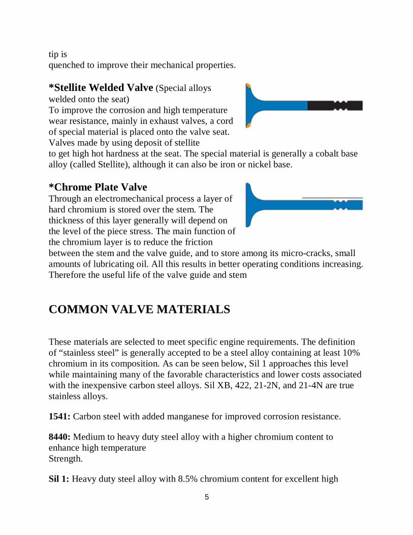
tip is quenched to improve their mechanical properties. *Stellite Welded Valve (Special alloys welded onto the seat) To improve the corrosion and high temperature wear resistance, mainly in exhaust valves, a cord of special material is placed onto the valve seat. Valves made by using deposit of stellite
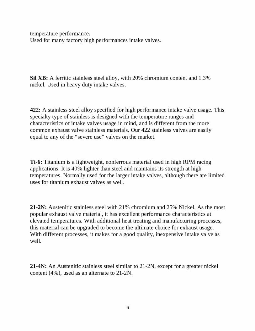
to get high hot hardness at the seat. The special material is generally a cobalt base alloy (called Stellite), although it can also be iron or nickel base. *Chrome Plate Valve Through an electromechanical process a layer of hard chromium is stored over the stem. The thickness of this layer generally will depend on the level of the piece stress. The main function of the chromium layer is to reduce the friction
between the stem and the valve guide, and to store among its micro-cracks, small amounts of lubricating oil. All this results in better operating conditions increasing. Therefore the useful life of the valve guide and stem
COMMON VALVE MATERIALS
These materials are selected to meet specific engine requirements. The definition of “stainless steel” is generally accepted to be a steel alloy containing at least 10% chromium in its composition. As can be seen below, Sil 1 approaches this level while maintaining many of the favorable characteristics and lower costs associated with the inexpensive carbon steel alloys. Sil XB, 422, 21-2N, and 21-4N are true stainless alloys.
1541: Carbon steel with added manganese for improved corrosion resistance.
8440: Medium to heavy duty steel alloy with a higher chromium content to enhance high temperature Strength.
Sil 1: Heavy duty steel alloy with 8.5% chromium content for excellent high
6
temperature performance. Used for many factory high performances intake valves.
Sil XB: A ferritic stainless steel alloy, with 20% chromium content and 1.3% nickel. Used in heavy duty intake valves.
422: A stainless steel alloy specified for high performance intake valve usage. This specialty type of stainless is designed with the temperature ranges and characteristics of intake valves usage in mind, and is different from the more common exhaust valve stainless materials. Our 422 stainless valves are easily equal to any of the “severe use” valves on the market.
Ti-6: Titanium is a lightweight, nonferrous material used in high RPM racing applications. It is 40% lighter than steel and maintains its strength at high temperatures. Normally used for the larger intake valves, although there are limited uses for titanium exhaust valves as well.
21-2N: Austenitic stainless steel with 21% chromium and 25% Nickel. As the most popular exhaust valve material, it has excellent performance characteristics at elevated temperatures. With additional heat treating and manufacturing processes, this material can be upgraded to become the ultimate choice for exhaust usage. With different processes, it makes for a good quality, inexpensive intake valve as well.
21-4N: An Austenitic stainless steel similar to 21-2N, except for a greater nickel content (4%), used as an alternate to 21-2N.
7
METAL FORMING PROCESS
Metalworking
Metalworking is the process of working with metals to create individual parts, assemblies, or large scale structures. The term covers a wide range of work from large ships and bridges to precise engine parts and delicate jewelry. It therefore includes a correspondingly wide range of skills, processes, and tools.
Metalworking is a science, art, hobby, industry and trade. Its historical roots span cultures, civilizations, and millennia. Metalworking has evolved from the discovery of smelting various ores, producing malleable and ductile metal useful for tools and adornments. Modern metalworking processes, though diverse and specialized, can be categorized as forming, cutting, or joining processes. Today's machine shop includes a number of machine tools capable of creating a precise, useful workpiece.
TYPES OF METAL FORMING:
Rolling Forging Extrusion Tube and Wire drawing Deep drawing
TYPES OF FORGING OPERATION
Forging was the first of the indirect compression-type process and it is probably the oldest method of metal forming.
It involves the application of a compressive stress, which exceeds the flow stress of the metal. The stress can either be applied quickly or slowly. The process can be
8
carried out hot or cold, choice of temperature being decided by such factors as whether ease and cheapness of deformation, production of certain mechanical properties or surface finish is the overriding factor.
There are two kinds of forging process:
1. Impact forging 2. Press forging.
In the former, the load is applied by impact, and deformation takes place over a very short time.
Press forging, on the other hand, involves the gradual build up of pressure to cause the metal to yield. The time of application is relatively long.
Over 90% of forging processes are hot.
1. Impact forging
Impact forging can be further subdivided into three types:
Smith forging, Drop forging, Upset forging.
Smith Forging
This is undoubtedly the oldest type of forging, but it is now relatively uncommon.
The impact force for deformation is applied manually by the blacksmith by means of a hammer. The piece of metal is heated in a forge and when at the proper temperature is placed on an anvil. This is a heavy mass of steel with a flat top, a horn which is curved for producing different curvatures, and a square hole in the top to accommodate various anvil fittings. While being hammered the metal is held with suitable tongs.
9
Formers are sometimes used; these have handles and are held onto the work piece by the smith while the other end is struck with a sledgehammer by a helper.
The surfaces of the formers have different shapes and are used to impart these shapes to the forgings.
One type of former, called fuller, has a well-rounded chisel-shaped edge and is used to draw out or extend the work piece. A fuller concentrates the blow and causes the metal to lengthen much more rapidly than can be done by using a flat hammer surface. Fullers are also made as anvil fittings so that the metal is drawn out using both a top and bottom fuller. Fittings of various shapes can be placed in the square hole in the anvil.
The working chisels are used for cutting the metal, punches and a block having proper-sized holes are used for punching out holes. Welding can be done by shaping the surfaces to be joined, heating the two pieces then adding a flux to the surfaces to remove scale and impurities. The two pieces are then hammered together producing welding.
The easiest metals to forge are the low and medium carbon steels and most smith forgings are made of these metals. The high carbon and alloy steels are more difficult to forge and require great care.
Drop Forging
This is the modern equivalent of smith forging where the limited force of the blacksmith has been replaced by the mechanical or steam hammer.
The process can be carried out by open forging where the hammer is replaced by a tup and the metal is manipulated manually on an anvil.
The quality of the products depends very much on the skill of the forger.
(i) Open forging
Open forging is used extensively for the cogging process where the work piece is reduced in size by repeated blows as the metal gradually passes under the forge.
10
The cogging of a prismatic bar can be used to assess the parameters involved and how they are controlled.
The objective is to reduce the thickness of the work piece in a stepwise sequence from end to end. Several passes may be required to complete the work and edging is usually carried out to control the width. The reduction in thickness is accompanied by elongation and spreading. The relative amounts of elongation and spread cannot be calculated theoretically but they have been determined experimentally for mild steel.
(ii) Die drop forging
Closed-die drop forging is widely used and the tup and anvil are replaced by dies. Matching dies fit into the anvil and the tup. The dies have a series of grooves and depressions cut into them and the work piece is passed in sequence through a shaping series.
These stations have names such as fullering, blocking, edging, bending and cut off. Where several stages are involved, care must be taken to ensure that the metal does not become excessively chilled before the last station is reached. To ensure that the die cavity is completely filled the volume of the starting billet is greater than that of the final forging.
The excess metal appears as a "flash" at each stage, this is a thin fin around the perimeter of the forging at the parting line. This flash is cut away in a further press operation generally at a high temperature. The weight of flash may be a small percentage of the total weight for forgings of simple shapes but may exceed the weight of the actual forging for those of complex shape.
Each size and shape of forging will thus require a separate set of forging and trimming dies. The production tolerance for the initial metal must involve excess, e.g. ~10 mm. The over-tolerance metal is accommodated by a gutter around the die cavity which allows the formation of the fin referred to earlier.
Upset Forging
11
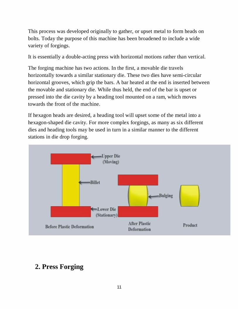
This process was developed originally to gather, or upset metal to form heads on bolts. Today the purpose of this machine has been broadened to include a wide variety of forgings.
It is essentially a double-acting press with horizontal motions rather than vertical.
The forging machine has two actions. In the first, a movable die travels horizontally towards a similar stationary die. These two dies have semi-circular horizontal grooves, which grip the bars. A bar heated at the end is inserted between the movable and stationary die. While thus held, the end of the bar is upset or pressed into the die cavity by a heading tool mounted on a ram, which moves towards the front of the machine.
If hexagon heads are desired, a heading tool will upset some of the metal into a hexagon-shaped die cavity. For more complex forgings, as many as six different dies and heading tools may be used in turn in a similar manner to the different stations in die drop forging.
2. Press Forging
12
Whereas impact forging usually involves a mechanical press, press forging, on the other hand, requires hydraulic power.
The largest forgings are invariably produced on large hydraulic presses. These have vertically moving rams, which move down slowly under considerable pressure.
A typical press forge would be capable of loads of the order of 6000 to 10000 tons.
Forgings up to 100 tons weight can be handled easily in this forge and the highest-quality products are manufactured by this technique.
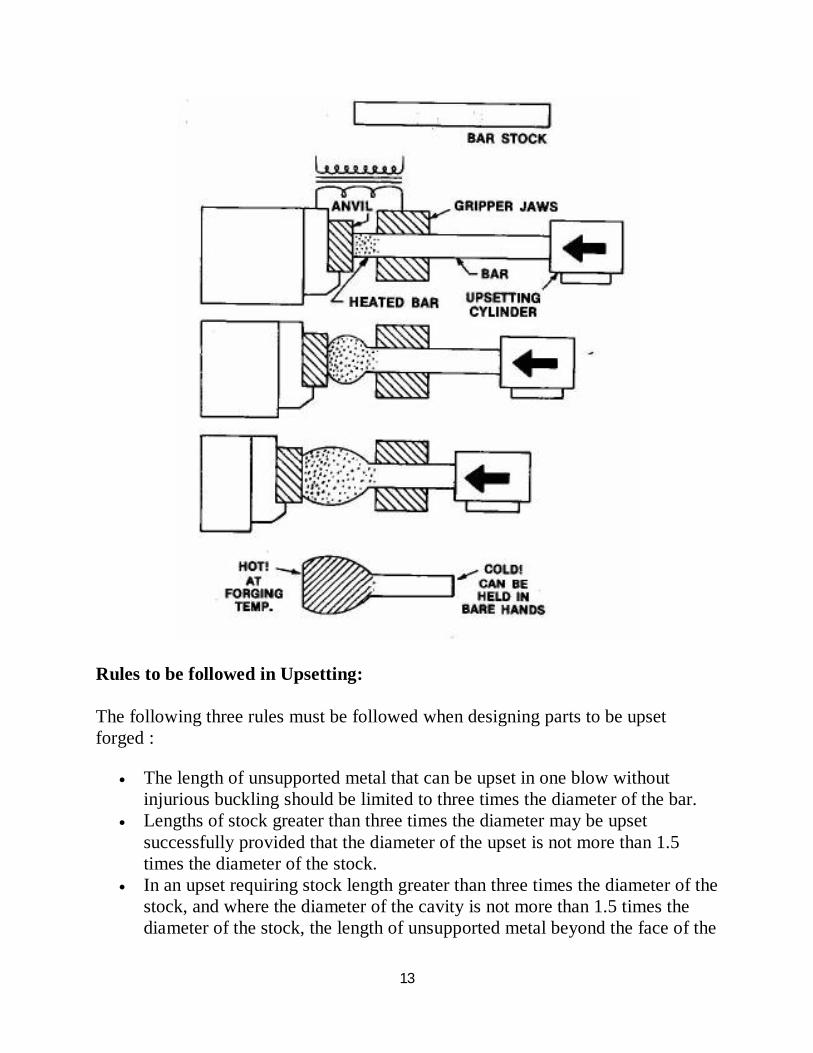
DETAILS OF UPSETTING PROCESS Upset forging increases the diameter of the workpiece by compressing its length. Based on number of pieces produced this is the most widely used forging process. A few examples of common parts produced using the upset forging process are engine valves, couplings, bolts, screws, and other fasteners. Upset forging is usually done in special high speed machines called crank presses, but upsetting can also be done in a vertical crank press or a hydraulic press. The machines are usually set up to work in the horizontal plane, to facilitate the quick exchange of workpieces from one station to the next.
The initial workpiece is usually wire or rod, but some machines can accept bars up to 25 cm (9.8 in) in diameter and a capacity of over 1000 tons. The standard upsetting machine employs split dies that contain multiple cavities. The dies open enough to allow the workpiece to move from one cavity to the next; the dies then close and the heading tool, or ram, then moves longitudinally against the bar, upsetting it into the cavity. If all of the cavities are utilized on every cycle then a finished part will be produced with every cycle, which is why this process is ideal for mass production.
13
Rules to be followed in Upsetting: The following three rules must be followed when designing parts to be upset forged :
The length of unsupported metal that can be upset in one blow without injurious buckling should be limited to three times the diameter of the bar.
Lengths of stock greater than three times the diameter may be upset successfully provided that the diameter of the upset is not more than 1.5 times the diameter of the stock.
In an upset requiring stock length greater than three times the diameter of the stock, and where the diameter of the cavity is not more than 1.5 times the diameter of the stock, the length of unsupported metal beyond the face of the
14
die must not exceed the diameter of the bar.
Upset forging increases cross-section by compressing the length, this is used in making heads on bolts and fasteners, valves and other similar parts. This process uses barstock which is heated at the end which is being forged. The bar is gripped in the fixed half of a die so that the length of material being forged projects. The forging blow is delivered by a moving die. Simple shapes are produced in a single stage but more complicated shapes require multiple stages. The process, if carried out cold is called cold heading. Mainly It's the production process under which high pressure deforms plastically metal into high strength components. It is also called hot heading process. Using this process cross-sectional size of a bar can be increased, either at ends or at some point along the length. Specially designed upsetting machines using closed dies are used to control size and shape. They can be made in various sizes. The mechanical press producing these components operates horizontally. The dies are split up allowing material to reach beyond the mechanical press. The forming force is supplied by a third die attached to the header. The process when done cold is called Cold Heading.
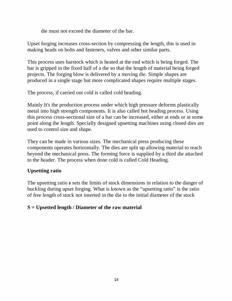
Upsetting ratio The upsetting ratio s sets the limits of stock dimensions in relation to the danger of buckling during upset forging. What is known as the “upsetting ratio” is the ratio of free length of stock not inserted in the die to the initial diameter of the stock S = Upsetted length / Diameter of the raw material
15
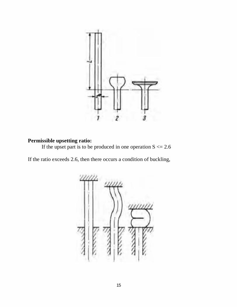
Permissible upsetting ratio: If the upset part is to be produced in one operation S <= 2.6 If the ratio exceeds 2.6, then there occurs a condition of buckling,
16
Advantages of Upset Forgings :
Greater Strength: As the material grain flow is oriented to the component's shape, compared to parts machined from bar stock, upset forgings offer greater strength.
Piercing and Trimming Operations: This contribute towards component weight reduction and eliminate machining operations.
Economical Production: As Upset forgings require fewer operations, have lower scrap costs, that can result in more cost efficient production
Application of Upset Forgings :
Artillery shells, cluster gear blanks, heads of bolts, valves, single and cylinders for radial engines are examples of parts made by upset forging.
17
ENGINE VALVE MANUFACTURING PROCESS
The valve manufacturing process is carried out by the following stages,
Cutting
The Special Centre-less grounded and 100%ultrasound crack detected round bars with H9 tolerances are cut smoothly into pieces.
Electric Upsetting Temperature and pressure controlled Upsetting machines process steel bar to critical temperature to prepare for smooth Hot Forging
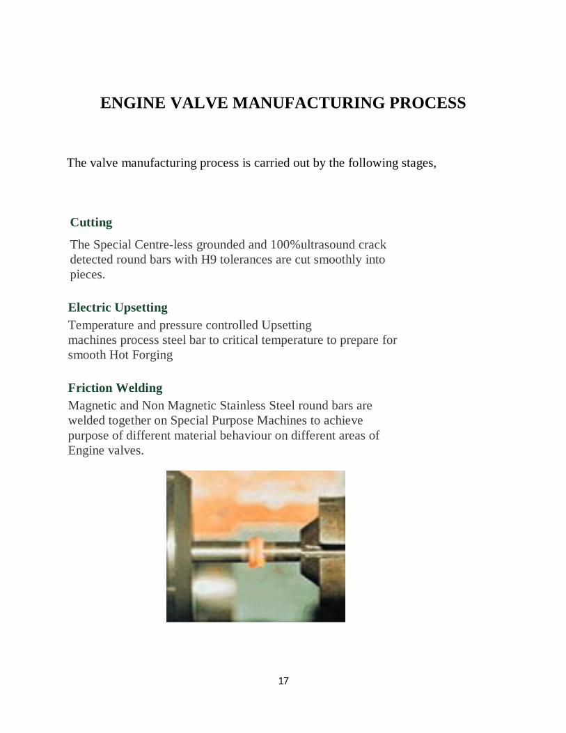
Friction Welding Magnetic and Non Magnetic Stainless Steel round bars are welded together on Special Purpose Machines to achieve purpose of different material behaviour on different areas of Engine valves.
18
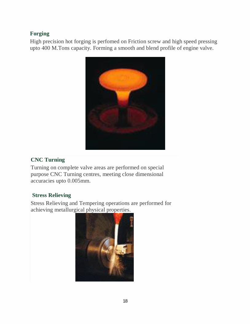
Forging High precision hot forging is perfomed on Friction screw and high speed pressing upto 400 M.Tons capacity. Forming a smooth and blend profile of engine valve.
CNC Turning Turning on complete valve areas are performed on special purpose CNC Turning centres, meeting close dimensional accuracies upto 0.005mm.
Stress Relieving Stress Relieving and Tempering operations are performed for achieving metallurgical physical properties.
19
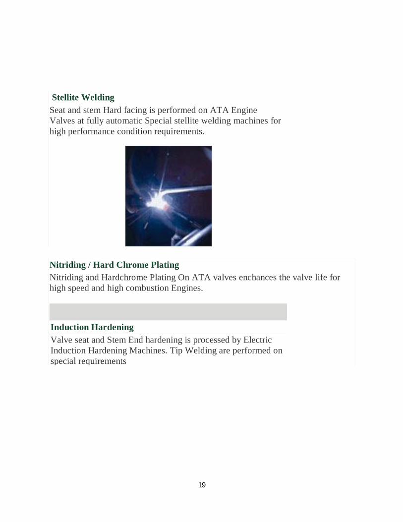
Stellite Welding Seat and stem Hard facing is performed on ATA Engine Valves at fully automatic Special stellite welding machines for high performance condition requirements.
Nitriding / Hard Chrome Plating Nitriding and Hardchrome Plating On ATA valves enchances the valve life for high speed and high combustion Engines.
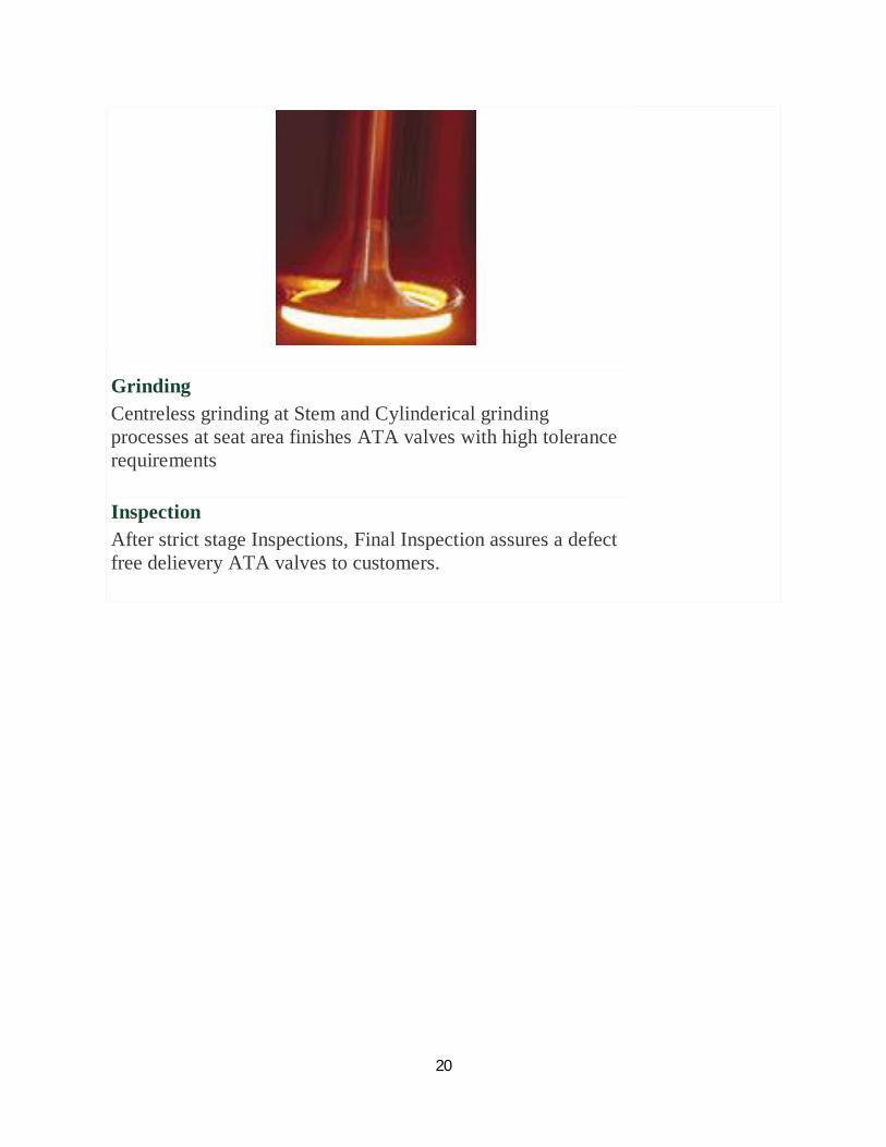
Induction Hardening Valve seat and Stem End hardening is processed by Electric Induction Hardening Machines. Tip Welding are performed on special requirements
20
Grinding Centreless grinding at Stem and Cylinderical grinding processes at seat area finishes ATA valves with high tolerance requirements
Inspection After strict stage Inspections, Final Inspection assures a defect free delievery ATA valves to customers.
21
22
ENGINE VALVE OUTLINE
23
UPSETTING PROCESS PARAMETRIC STUDY ON ENGINE VALVES
The current valve design and manufacturing process follows the Trial and Error method, fixing an assumed data on any parameters and then giving a trial run on the assumed parameters and then verifying it and fixing the standards.
This procedure may not be successful for all kinds of valves. It may lead to heavy loss in the material stock, loss in time, loss in money, loss in labour, etc. So to avoid these losses, standardization in the technique of manufacturing of valves is mandatory. And the most important step in the valve manufacturing process is Upsetting process. The entire valve design is based on the upset process and the bulb formed due to the upsetting process.
Objectives To study the upsetting process in the engine valve manufacturing process
To analyze and denote the parameters involved with the process and the work material
To dimension the parameters obtained for several patterns
To correlate the parameters for every pattern
To wind up with a relation for the dependent and varying parameters
To denote a standard relationships to the parameters which influence the Upsetting process in the manufacture of engine valves
24
Present system of Engine valve manufacturing process commonly receives the following data,
Raw material details
Valve head diameter
Valve seat diameter
Overall Length of the valve
Seat angle
Stem length
Stem diameter
These data are only applicable to the valve design and for inspection and testing of valves, but the other parameters involved in the manufacturing process are not said or defined.
Such parameters include,
Upsetting time
Upsetting pressure & Return pressure
Voltage & current to be set during Upsetting process
Temperature to be maintained during Upsetting process
Length & Diameter of the raw material for a specific Valve head diameter
Material to be chosen
25
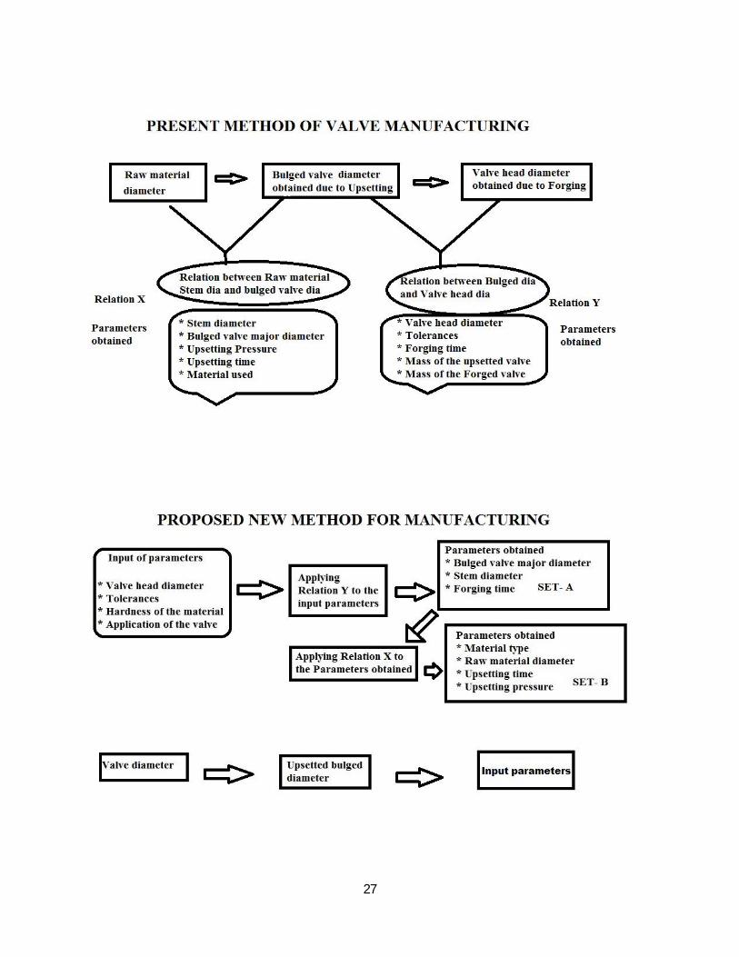
As per the current system there is no direct relation between the raw material parameters and the finished valve parameters. So a standard technique is not possible to be put forth for the valve manufacturing process especially to the upsetting process.
So to arrive at the parameter relationships, a detailed study is made on the upsetting process in the Valve manufacturing process. The current process is carried out as follows,
(i) The raw material is chosen as per the desired Valve design and it is cut into several cut-bars.
(ii) The cut-bars are sent to the shops and they are inspected for the diameter and length.
(iii) Then 5 pieces of cut-bars are selected and they are placed over the ram of the Electric Upsetting machine and then the ram movement distance is adjusted based on the bulb to be formed
(iv) Then other parameters like Upsetting pressure, Return pressure, Temperature of the anvil, Voltage, Current are set on an assumption
(v) Then the upsetting process is carried out on Trial basis, and then the upsetted material is sent for forging
(vi) The Forging die consists of the design of the valve to be obtained and the forging operation is done
(vii) Then the five pieces are checked for any dimensional variations, if there are no variations the process is further preceded, but when there are occurrences of variation, the respective parameter is varied and then again the same procedure is repeated.
Obviously, this sounds to be a tedious process and hence a technique is needed to simplify the upsetting process.

26
PROJECT PLAN: A set of samples of different patterns of valves are chosen based on criteria
like Head diameter, customer, Overall length, Material, Type of the valve.
Then the materials are upsetted using the Electric Upsetting process.
The parameters related to the upsetting process are noted down and then they are analyzed.
The parameters for all the patterns are grouped and they are correlated.
The variations are noted down and the possible and effective ratios are zeroed down.
These ratios are analyzed and standard relations are obtained.
27
28
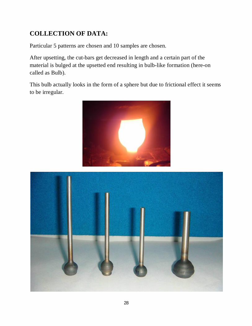
COLLECTION OF DATA:
Particular 5 patterns are chosen and 10 samples are chosen.
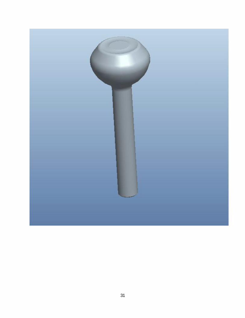
After upsetting, the cut-bars get decreased in length and a certain part of the material is bulged at the upsetted end resulting in bulb-like formation (here-on called as Bulb).
This bulb actually looks in the form of a sphere but due to frictional effect it seems to be irregular.
29
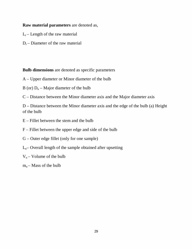
Raw material parameters are denoted as,
Lr – Length of the raw material
Dr – Diameter of the raw material
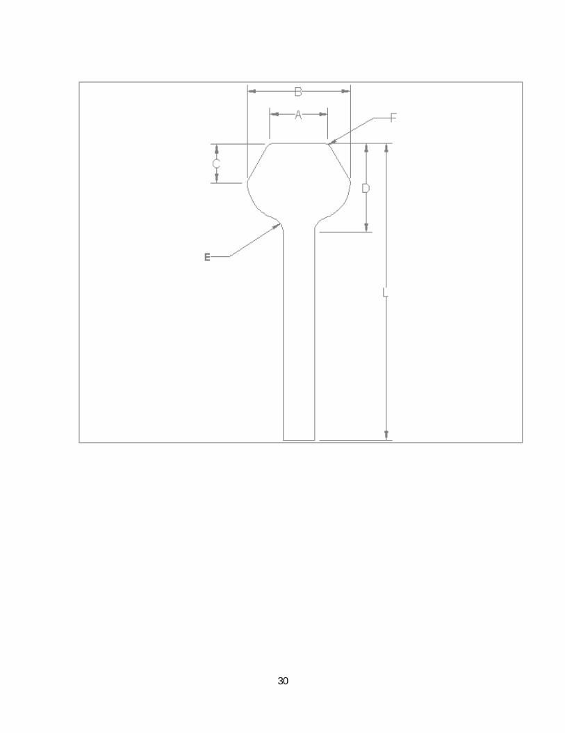
Bulb dimensions are denoted as specific parameters
A – Upper diameter or Minor diameter of the bulb
B (or) Du – Major diameter of the bulb
C – Distance between the Minor diameter axis and the Major diameter axis
D – Distance between the Minor diameter axis and the edge of the bulb (a) Height of the bulb
E – Fillet between the stem and the bulb
F – Fillet between the upper edge and side of the bulb
G – Outer edge fillet (only for one sample)
Lu– Overall length of the sample obtained after upsetting
Vu – Volume of the bulb
mu – Mass of the bulb
30
31
32
Valve parameters are denoted as (after forging),
Df – Diameter of the forged head
Vf – Volume of the forged head
mf – Mass of the forged head
Lf – Length of the forged valve
Lh – Length of the forged head
Other parameters are denoted as,
tup – Upsetting time
Pu – Upsetting pressure
Pret – Return pressure
vu – Upsetting Velocity
T – Temperature maintained during upsetting process
After all these data are collected, they are tabulated.
33
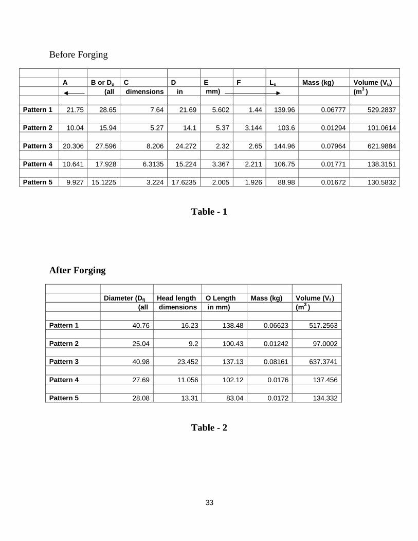
Before Forging
A B or Du C D E F Lu Mass (kg) Volume (Vu) (all dimensions in mm) (m3 ) Pattern 1 21.75 28.65 7.64 21.69 5.602 1.44 139.96 0.06777 529.2837 Pattern 2 10.04 15.94 5.27 14.1 5.37 3.144 103.6 0.01294 101.0614 Pattern 3 20.306 27.596 8.206 24.272 2.32 2.65 144.96 0.07964 621.9884 Pattern 4 10.641 17.928 6.3135 15.224 3.367 2.211 106.75 0.01771 138.3151 Pattern 5 9.927 15.1225 3.224 17.6235 2.005 1.926 88.98 0.01672 130.5832
Table - 1
After Forging
Diameter (Df) Head length O Length Mass (kg) Volume (Vf ) (all dimensions in mm) (m3 ) Pattern 1 40.76 16.23 138.48 0.06623 517.2563 Pattern 2 25.04 9.2 100.43 0.01242 97.0002 Pattern 3 40.98 23.452 137.13 0.08161 637.3741 Pattern 4 27.69 11.056 102.12 0.0176 137.456 Pattern 5 28.08 13.31 83.04 0.0172 134.332
Table - 2
34
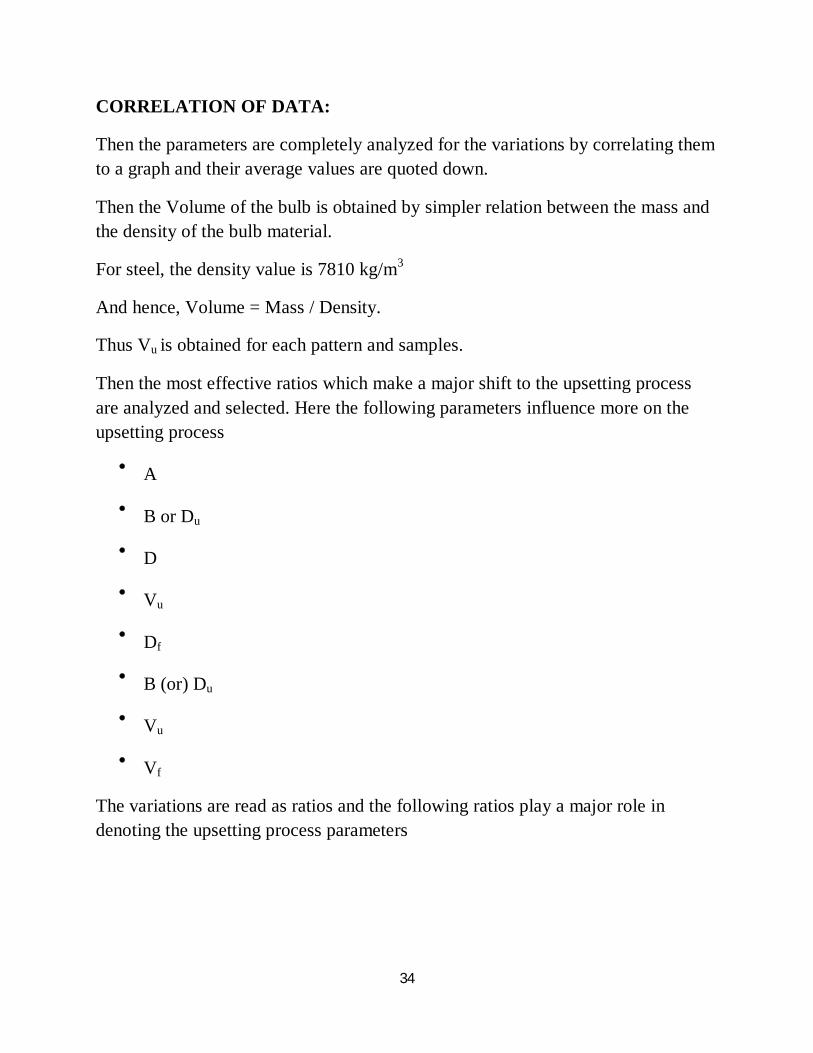
CORRELATION OF DATA:
Then the parameters are completely analyzed for the variations by correlating them to a graph and their average values are quoted down.
Then the Volume of the bulb is obtained by simpler relation between the mass and the density of the bulb material.
For steel, the density value is 7810 kg/m3
And hence, Volume = Mass / Density.
Thus Vu is obtained for each pattern and samples.
Then the most effective ratios which make a major shift to the upsetting process are analyzed and selected. Here the following parameters influence more on the upsetting process
A
B or Du
D
Vu
Df
B (or) Du
Vu
Vf
The variations are read as ratios and the following ratios play a major role in denoting the upsetting process parameters
35
Df / Du Vf / Vu B/D or Du / D A/B A/D Pattern 1 1.422688 0.977276 1.320885 0.759162 1.002766 Pattern 2 1.570891 0.959815 1.130496 0.629862 0.712057 Pattern 3 1.484998 1.024736 1.136948 0.735831 0.836602 Pattern 4 1.544511 0.993789 1.177614 0.593541 0.698962 Pattern 5 1.856836 1.028708 0.858087 0.656439 0.563282 Avg 1.575985 0.996865 1.124806 0.674967 0.762734
Table – 3
Du / Df Lu / Lr D / Dr Lr / D Du / Dr Pattern1 0.702895 0.553202 2.357609 11.66436 3.11413 Pattern2 0.636581 0.643782 2.473684 11.06383 2.796491 Pattern3 0.673402 0.540896 2.582128 11.04153 2.935745 Pattern4 0.647454 0.586538 2.670877 11.95481 3.145263 Pattern5 0.538551 0.71184 3.175225 10.21421 2.724775 Average 0.639777 0.607252 2.651905 10.21421 2.943281
Table – 4
36
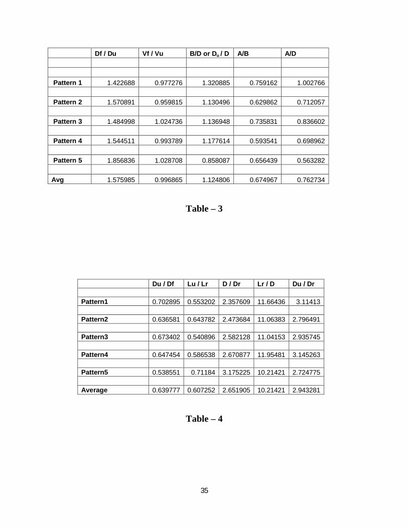
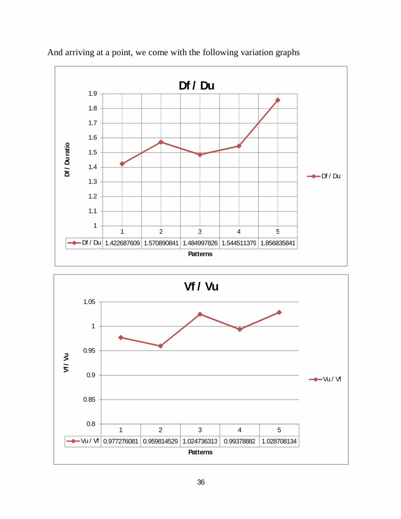
And arriving at a point, we come with the following variation graphs
1 2 3 4 5
Df / Du 1.422687609 1.570890841 1.484997826 1.544511379 1.856835841
1
1.1
1.2
1.3
1.4
1.5
1.6
1.7
1.8
1.9
Df /
Du
rati
o
Patterns
Df / Du
Df / Du
1 2 3 4 5
Vu / Vf 0.977276081 0.959814529 1.024736313 0.99378882 1.028708134
0.8
0.85
0.9
0.95
1
1.05
Vf /
Vu
Patterns
Vf / Vu
Vu / Vf
37
1 2 3 4 5
A/B 0.759162304 0.629861982 0.73583128 0.59354083 0.656439081
0
0.1
0.2
0.3
0.4
0.5
0.6
0.7
0.8A
/B
Patterns
A/B
A/B
1 2 3 4 5
A/D 1.002766252 0.712056738 0.836601846 0.698962165 0.563281981
0
0.2
0.4
0.6
0.8
1
1.2
A/D
Patterns
A/D
A/D
38
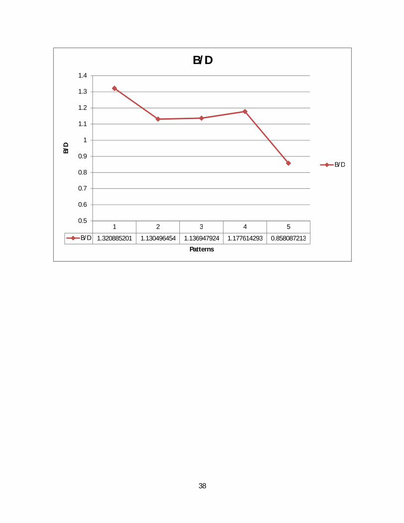
1 2 3 4 5
B/D 1.320885201 1.130496454 1.136947924 1.177614293 0.858087213
0.5
0.6
0.7
0.8
0.9
1
1.1
1.2
1.3
1.4
B/D
Patterns
B/D
B/D
39
Thus we can conclude with the following relations
D = 2.651905* Dr
Du = 2.943281* Dr
So, from this we know that when the Raw material diameter (Dr) is given then the bulb height (D) and bulb major diameter (Du) can be obtained.
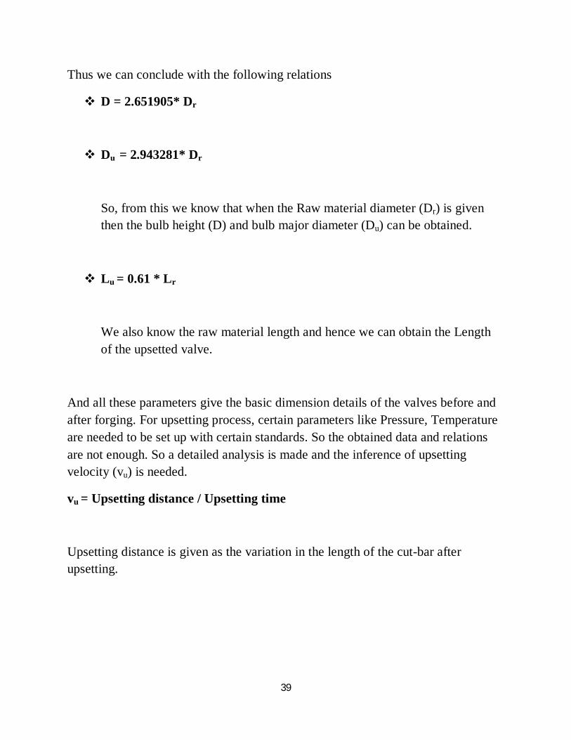
Lu = 0.61 * Lr
We also know the raw material length and hence we can obtain the Length of the upsetted valve.
And all these parameters give the basic dimension details of the valves before and after forging. For upsetting process, certain parameters like Pressure, Temperature are needed to be set up with certain standards. So the obtained data and relations are not enough. So a detailed analysis is made and the inference of upsetting velocity (vu) is needed.
vu = Upsetting distance / Upsetting time
Upsetting distance is given as the variation in the length of the cut-bar after upsetting.
40
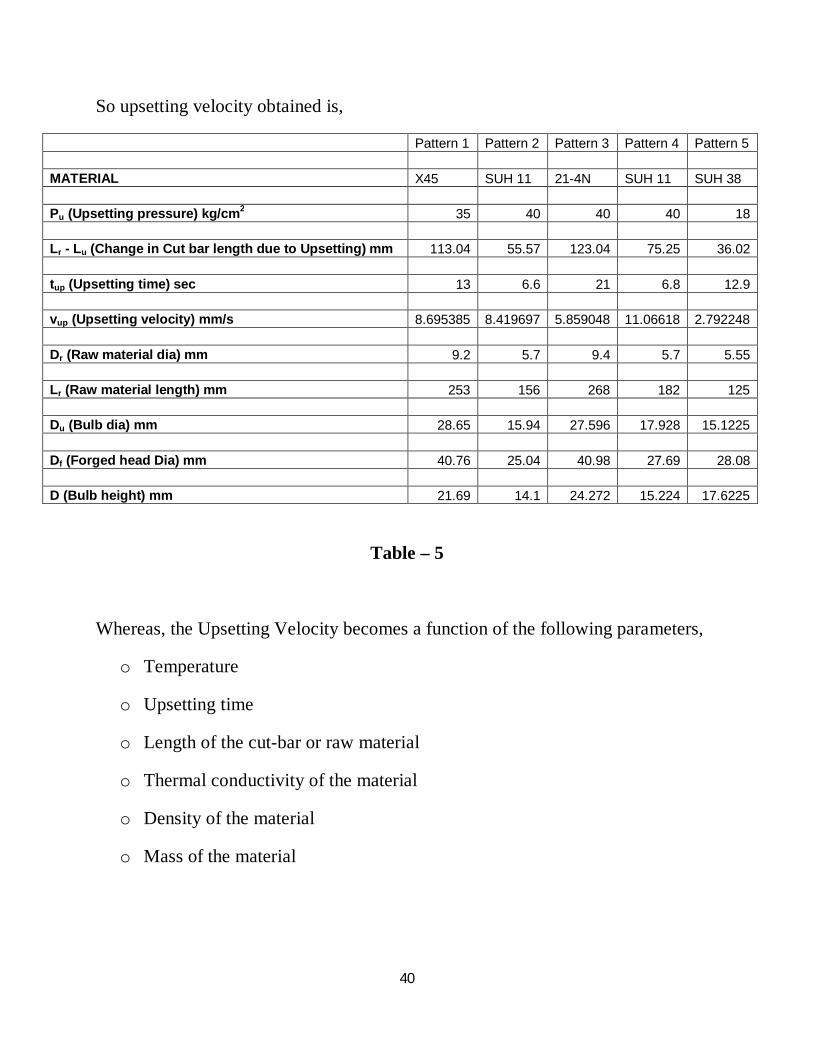
So upsetting velocity obtained is,
Pattern 1 Pattern 2 Pattern 3 Pattern 4 Pattern 5 MATERIAL X45 SUH 11 21-4N SUH 11 SUH 38 Pu (Upsetting pressure) kg/cm2 35 40 40 40 18 Lr - Lu (Change in Cut bar length due to Upsetting) mm 113.04 55.57 123.04 75.25 36.02 tup (Upsetting time) sec 13 6.6 21 6.8 12.9 vup (Upsetting velocity) mm/s 8.695385 8.419697 5.859048 11.06618 2.792248
Dr (Raw material dia) mm 9.2 5.7 9.4 5.7 5.55 Lr (Raw material length) mm 253 156 268 182 125
Du (Bulb dia) mm 28.65 15.94 27.596 17.928 15.1225 Df (Forged head Dia) mm 40.76 25.04 40.98 27.69 28.08 D (Bulb height) mm 21.69 14.1 24.272 15.224 17.6225
Table – 5
Whereas, the Upsetting Velocity becomes a function of the following parameters,
o Temperature
o Upsetting time
o Length of the cut-bar or raw material
o Thermal conductivity of the material
o Density of the material
o Mass of the material
41
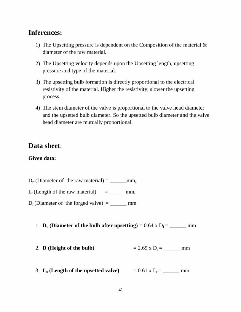
Inferences:
1) The Upsetting pressure is dependent on the Composition of the material & diameter of the raw material.
2) The Upsetting velocity depends upon the Upsetting length, upsetting pressure and type of the material.
3) The upsetting bulb formation is directly proportional to the electrical resistivity of the material. Higher the resistivity, slower the upsetting process.
4) The stem diameter of the valve is proportional to the valve head diameter and the upsetted bulb diameter. So the upsetted bulb diameter and the valve head diameter are mutually proportional.
Data sheet:
Given data:
Dr (Diameter of the raw material) = ______mm,
Lr (Length of the raw material) = ______mm,
Df (Diameter of the forged valve) = ______ mm
1. Du (Diameter of the bulb after upsetting) = 0.64 x Df = ______ mm
2. D (Height of the bulb) = 2.65 x Dr = ______ mm
3. Lu (Length of the upsetted valve) = 0.61 x Lr = ______ mm
42
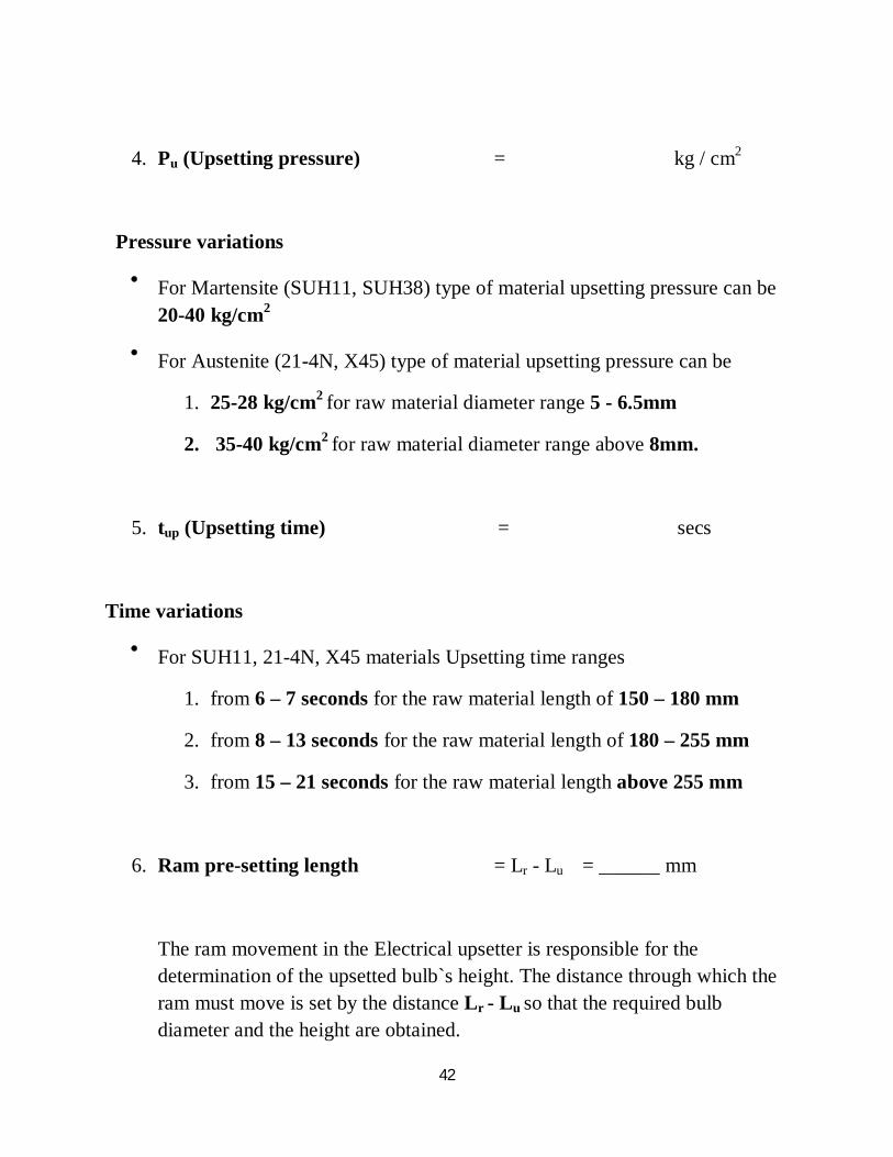
4. Pu (Upsetting pressure) = kg / cm2
Pressure variations
For Martensite (SUH11, SUH38) type of material upsetting pressure can be 20-40 kg/cm2
For Austenite (21-4N, X45) type of material upsetting pressure can be
1. 25-28 kg/cm2 for raw material diameter range 5 - 6.5mm
2. 35-40 kg/cm2 for raw material diameter range above 8mm.
5. tup (Upsetting time) = secs
Time variations
For SUH11, 21-4N, X45 materials Upsetting time ranges
1. from 6 – 7 seconds for the raw material length of 150 – 180 mm
2. from 8 – 13 seconds for the raw material length of 180 – 255 mm
3. from 15 – 21 seconds for the raw material length above 255 mm
6. Ram pre-setting length = Lr - Lu = ______ mm
The ram movement in the Electrical upsetter is responsible for the determination of the upsetted bulb`s height. The distance through which the ram must move is set by the distance Lr - Lu so that the required bulb diameter and the height are obtained.

43
Advantages of the proposed system:
Material loss and scrap loss is reduced
Time effective process
Updating the design and the process is possible
Easier operation and work flow
Quicker setting of the parameters
Increment in productivity is evident
Capital and manufacturing cost are reduced
44
CONCLUSION:
These conclusions are derived based on the sampling of the data obtained by certain valves manufactured at the premises according to the customer standards and the proposals made by these conclusions may admit that a better standard of working in the Upsetting process involved in the manufacturing of engine valves. If these proposals are carried out there may be an advantage of improvement of the process parameters and wastage of material with reduction in time.
This proposal may reduce the work load and the parameter settings based on trial and error methodology. A straight-away setting of the parameters may result in increased productivity and improvement in the work flow in the shops.
The obtained results allow for supposing that larger individualization in determining the limiting dependencies is necessary. It will be useful for more effective technological applications of the given process for different material. Thus the proposal may be carried forward for betterment in the procedure of Upsetting process.