Embed Size (px)
Citation preview

Report Documentation Page Form ApprovedOMB No. 0704-0188
Public reporting burden for the collection of information is estimated to average 1 hour per response, including the time for reviewing instructions, searching existing data sources, gathering andmaintaining the data needed, and completing and reviewing the collection of information. Send comments regarding this burden estimate or any other aspect of this collection of information,including suggestions for reducing this burden, to Washington Headquarters Services, Directorate for Information Operations and Reports, 1215 Jefferson Davis Highway, Suite 1204, ArlingtonVA 22202-4302. Respondents should be aware that notwithstanding any other provision of law, no person shall be subject to a penalty for failing to comply with a collection of information if itdoes not display a currently valid OMB control number.
1. REPORT DATE JUL 1979
2. REPORT TYPE N/A
3. DATES COVERED -
4. TITLE AND SUBTITLE Practical Shipbuilding Standards for Surface Preparation and Coatings
5a. CONTRACT NUMBER
5b. GRANT NUMBER
5c. PROGRAM ELEMENT NUMBER
6. AUTHOR(S) 5d. PROJECT NUMBER
5e. TASK NUMBER
5f. WORK UNIT NUMBER
7. PERFORMING ORGANIZATION NAME(S) AND ADDRESS(ES) Naval Surface Warfare Center CD Code 2230 - Design Integration ToolsBldg 192 Room 128 9500 MacArthur Blvd Bethesda, MD 20817-5700
8. PERFORMING ORGANIZATIONREPORT NUMBER
9. SPONSORING/MONITORING AGENCY NAME(S) AND ADDRESS(ES) 10. SPONSOR/MONITOR’S ACRONYM(S)
11. SPONSOR/MONITOR’S REPORT NUMBER(S)
12. DISTRIBUTION/AVAILABILITY STATEMENT Approved for public release, distribution unlimited
13. SUPPLEMENTARY NOTES
14. ABSTRACT
15. SUBJECT TERMS
16. SECURITY CLASSIFICATION OF: 17. LIMITATION OF ABSTRACT
SAR
18. NUMBEROF PAGES
63
19a. NAME OFRESPONSIBLE PERSON
a. REPORT unclassified
b. ABSTRACT unclassified
c. THIS PAGE unclassified
Standard Form 298 (Rev. 8-98) Prescribed by ANSI Std Z39-18

A SUBSIDIARY OF OGDEN CORPORATION .
P. O. BOX 50280, • NEW ORLEANS, LA. 7015D • PHONE: 436-2I2 l ● AREA CODE 504
Dear Sir:
Subject:
Reference:
WESTERN UN1ON TELEX:ENGINEERING AVONENG NLN 58-245 PURCHASING AVONPUR NLN 58-246
January 17, 1980
National Shipbuilding Reports
(1) Practical shipbuilding Standards forSurface Preparation and Coatings
(2) Marine Coatings Performance for.Different Ship Areas, Vol. I and II
The subject reports are enclosed for your information. The nationalShipbuilding Research Program is a rest-shared program of the MaritimeAdministration and the shipbuilding industry dedicated to the inhancement of manufacturing technology and the reduction of ship production costs.--
The reference programs are a cost shared effort of Avondale shipyards, Inc. The investigation was performed by Offshore Power Systems, Mr. Benjamin
S. Fultz, program Manager.
The executive summaries will provide you with a concise synopsis of the investigations.
Reference (1) Program resulted in the following:
Developmmt of a proposed Shipbuilding Standard for Surface pre-paration and Coatings
Development of a Standard “Paints and Coatings Product/ProcedureData sheet”
Identified the need for preconstruction conferences between theowner, applicator and paint suppliers
This conference would result in the choice of painting systems that would be Comparable with the shipyard’s climatic conditions and manufacturingmethodology, resulting in the reduction in application cost and the reductionof coating failures. -
The objective of the reference (2) Project was to establish methods to reduce ship construction costs by improving the paint selection system.Toward this end, the following results were achieved:

Page 2January 17, 1980
Establishment of a ccmputer program of paint service histories whichdemonstrate that valid conclusions can be reached as to whichgeneric paint type is best for a specified area of this ship.
Support by laboratory testing of performnce trends of the computerprogram analysis
Demonstration by laboratory testing- that carefulsuppliers is necessary
Indications that careful. selection of labaratoryevaluation parameters, to duplicate service conditions, can serve asa screening method for candidate paint(s)
evaluation of paint
test methods and.
Establishment of craft interface and premature area release forpainting Prior to compartment completion. That is, poor paint plan-ning and scheduling is the major cause of inordinately high shippainting costs.
If the principles identified within the body of this report are as-similatd by the marine industry; many dollars in improved ship paintperformance will be realized. shipbuilders will benefit in two (2) ways:
Less dollars expended at guarantee survey timeperformance ( fewer failures)
Reduction in the probability of a catastrophicvessel construction
due to improved paint
paint failure during
These prcgrams have identified high cost problem areas and have recom-mended procedures that, when implemented, will result in meaningful costsavings. Effective implementation is dependent upon the response of theindividual yards and the cooperative effort of the industry.
Sincerely yours,
, AVONDALE SHIPYARDS, INC.
J.W. Peart Program Manager
JWP/mag
Attachments

TABLE OF CONTENTSFOREWORD
EXECUTIVE SUMMARY
LIST OF FIGURES
1. CONCLUSIONS1.1 Cost Savings in Standards Utilization1.2 Use of Paints & Coatings Product/Procedure Data Sheet1.3 Continued Research and Development
2. PROJECT PLAN OF ACTION AND RESULTS2.I Objective2.2 General Approach2.3 Determination of Surface Preparation and Coating Practices2.3 Utilized by U.S. and Foreign Shipyards2.4 Scope of Standards to be Developed
2.4.1 Definition of Standards2.4.2.1 AMERICAN STANDARDS
2.4.2.1.1 Steel Structures Painting Council (SSPC)2.4.2.1.2 National Association of Corrosion Engineers (NACE)2.4.2.1.3 The Society of Naval Architects and
Marine Engineers (SNAME)2.4.2.1.4 American Society for Testing and Materials (ASTM)2.4.2.1.5 Others
2.4.2.2. BRITISH STANDARDS2.4.2.2.1 Code of Practice for Cleaning and Preparation
of Metal Surfaces (CP 3012:1972)2.4.2.2.2 Specification for Surface Finish of Blast-Cleaned
Steel for Painting (BS 4232:1967)2.4.2.2.3 Code of Practice for Protective Coatings of Iron and
Steel Structures Against Corrosion (BS 5493:1977)2.4.2.3 JAPANESE STANDARDS
2.4.2.3.1 Standard for the Preparation of SteelSurfaces to Painting (SPSS)
2.4.2.4 SWEDISH STANDARDS2.4.2.4.1 Pictorial Surface Preparation Standards for
Painting Steel Surfaces2.4.2.4 FRENCH STANDARDS
2.5 Development of Shipbuilding Standards2.6 Development of Paints and Coatings Product/Procedure Data Sheet
3. PAINTS AND COATINGS PRODUCT/PROCEDURE DATA SHEET3.1 Instructions3.2 Blank Paints & Coatings Product/Procedure Data Sheets3.3 Sample Paints & Coatings Product/Procedure Data Sheets
3.3.1 Primer3.3.2 Topcoat
4. PRACTICAL SHIPBUILDING SURFACE PREPARATIONAND COATINGS STANDARDS
5. BIBLIOGRAPHY
ii
iv
iv
1-11-21-3
2-12-1
2-12-22-22-22-22-3
2-32-32-42-4
2-4
2-4
2-42-5
2-52-5
2-52-52-52-5
3-13-23-33-33-3

FOREWORD
This research project was performed under the National Shipbuilding Research ogram. The project, as part ofthis program, is a cooperative cost shared effort between the Maritime Administration, Avondale Shipyards, Inc.and Offshore Power Systems, a wholly owned Westinghouse subsidiary. The overall objective of the program isimproved productivity and, therefore, reduced shipbuilding costs to meet the lower Construction DifferentialSubsidy rate goals of the Merchant Marine Act of 1970.
The studies have been undertaken with this goal in mind, and have followed closely the project outlineapproved by the Society of Naval Architects and Marine Engineers’ (SNAME) Ship Production Committee. Theresearch effort for the project was assigned, by subcontract, to Offshore Power Systems.
Mr. Benjamin S. Fultz, Mr. P.J. Hawkins and Mr. Dave Sealander, of Offshore Power Systems, served as ProjectManager and Senior Engineers respectively. On behalf of Avondale Shipyards, Inc., Mr. John Peart was the R & DProject Manager responsible for technical direction and the editing and publishing of this report. Program defin-ition and guidance was provided by the members of the 023-1 Surface Preparation Coatings Committee ofSNAME, Mr. C.J. Starkenburg, Avondale Shipyards, Inc., Chairman.
Special thanks is also extended to Mr. William Arbiter, who reviewed the draft of this report and offeredvaluable criticism. Also, we wish to acknowledge the support of Mr. Jack Carvey and Mr. Robert Schaffran, ofthe Maritime Administration, and the contributions of the following corporations:
Ameron Corrosion Control Divison, Beria, CaliforniaAvondale Shipyards, Inc., New Orleans, LouisianaBath Iron Works Corporation, Bath, MaineBethlehem Steel Corporation, Beaumont, TexasBriner Paint Manufacturing Company, Corpus Christi, TexasCarboline Marine Corporation, St. Louis, MissouriDavies Shipbuilding Limited, Quebec, CanadaDevoe and Raynolds Company, Louisville, KentuckyDillingham Shipyard, Honolulu, HawaiiDrave Corp. Engineering Works Division, Pittsburgh, PennsylvaniaEquitable Shipyards, Inc., New Orleans, LouisianaExxon International Company, Houston, TexasGeneral Dynamics, Electric Boat Division, Groton, ConnecticutGeneral Dynamics, Quincy Shipbuilding Division, Quincy, MassachusettsHempel Marine Paints Inc., New York, New YorkIngall’s Shipbuilding Corporation, Pascagoula, MississippiImperial Coatings Corporation, New Orleans, LouisianaInternational Paint Company, Inc., New York, New YorkJeff boat Inc., Jefferson, IndianaKaiser Steel Corporation, Napa, CaliforniaKeeler and Long Inc., Watertown, ConnecticutLockheed Shipbuilding & Construction Co., Seattle, WashingtonLongbeach Naval Shipyard, Long Beach, CaliforniaMaxon Marine Industries, Inc., Tell City, IndianaMilitary Sealift Command, Washington, D.C.Mobil Chemical Company, Edison, New JerseyMobile Paint Manufacturing Company, Mobile, Alabama
ii
M & T Chemicals, Inc., Rahway, New JerseyNAPKO Corporation, Houston, TexasNewport News Shipbuilding Corporation, Newport News, VirginiaOffshore Power Systems, Jacksonville, FloridaPearl Harbor Naval Shipyard, FPO, San Francisco, CaliforniaPeterson Builders, Inc., Sturgeon Bay, WisconsinPorter Coatings, Louisville KentuckySeatrain Shipbuilding Corporation, Brooklyn, New YorkSigma Coatings, Harvey, LouisianaSun Shipbuilding and Drydock Company, Chester, PennsylvaniaTacoma Boatbuilding Company, Inc., Tacoma, WashingtonTampa Ship Repair & Dry Dock, Inc., Tampa, FloridaTodd Shipyards Corporation, Los Angeles, CaliforniaTnemec Company Inc., Kansas City, MissouriShipbuilding Consultants, Dickerson, Texas
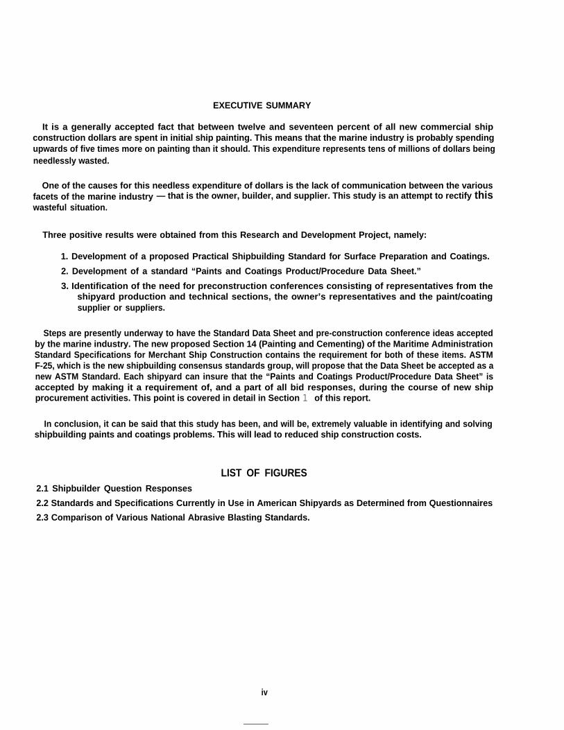
EXECUTIVE SUMMARY
It is a generally accepted fact that between twelve and seventeen percent of all new commercial shipconstruction dollars are spent in initial ship painting. This means that the marine industry is probably spendingupwards of five times more on painting than it should. This expenditure represents tens of millions of dollars beingneedlessly wasted.
One of the causes for this needless expenditure of dollars is the lack of communication between the variousfacets of the marine industry — that is the owner, builder, and supplier. This study is an attempt to rectify thiswasteful situation.
Three positive results were obtained from this Research and Development Project, namely:
1. Development of a proposed Practical Shipbuilding Standard for Surface Preparation and Coatings.
2. Development of a standard “Paints and Coatings Product/Procedure Data Sheet.”
3. Identification of the need for preconstruction conferences consisting of representatives from theshipyard production and technical sections, the owner’s representatives and the paint/coatingsupplier or suppliers.
Steps are presently underway to have the Standard Data Sheet and pre-construction conference ideas acceptedby the marine industry. The new proposed Section 14 (Painting and Cementing) of the Maritime AdministrationStandard Specifications for Merchant Ship Construction contains the requirement for both of these items. ASTMF-25, which is the new shipbuilding consensus standards group, will propose that the Data Sheet be accepted as anew ASTM Standard. Each shipyard can insure that the “Paints and Coatings Product/Procedure Data Sheet” isaccepted by making it a requirement of, and a part of all bid responses, during the course of new shipprocurement activities. This point is covered in detail in Section 1 of this report.
In conclusion, it can be said that this study has been, and will be, extremely valuable in identifying and solvingshipbuilding paints and coatings problems. This will lead to reduced ship construction costs.
LIST OF FIGURES2.1 Shipbuilder Question Responses
2.2 Standards and Specifications Currently in Use in American Shipyards as Determined from Questionnaires
2.3 Comparison of Various National Abrasive Blasting Standards.
iv

SECTION 1
Conclusion

1. CONCLUSION
1.1 Cost Savings In Standards UtilizationIt has long been apparent to knowledgeable
persons in the field of coatings for marinestructures, that a three way interest exists.Coating suppliers market materials whichrepresent the best economic advantage to theirparticular company; i.e., some companiesspecialize in zinc rich paints, others in epoxies, etc.The shipowner is primarily interested in in-serviceperformance, not truly understanding or caringfor the problems of application under adverseshipyard conditions. The shipbuilder wants to beable to apply the specified coating system withavailable resources without delays. In reality, allare desirous of achieving the best coating systembased on the lowest life cycle cost.
This apparent lack of empathy among thedifferent facets of the shipbuilding industry isprimarily due to lack of standardization and acommon baseline of communication. The endresult of this misunderstanding is added shipproduction costs.
Coating systems must be designed and qualifiedas totally integrated, all encompassing systems.The surface condition of the substance material,the primer, top coats and their applicationenvironment must be considered in the choice ofthe system. The coating system must be fullyqualified by the coating suppliers, shipowners,and shipyard applicators, with constraintsestablished on all materials and procedures tomake the coating systems dependable, producible,economical and long lasting with minimummaintenance.
It was the objective of this research anddevelopment program to establish workable,economical standards governing the preparationand characterization of prepared surfaces, theapplication of coating systems, and thestandardization of materials. These standardsmust represent the concensus of the requirementsof all sections of the coatings community and mustultimately be universally applied and enforced.The final acceptance of a set of practicalshipbuilding standards for surface preparationand coatings will provide a common baseline ofcommunication which will result in cost savingsand increased credibility among all personsconcerned.
1.2 Use of Paints and CoatingsProduct/Procedure Data Sheet
An important result of this study is the “Paintsand Coatings Product/Procedure Data Sheet”contained in Section 3 of this report. This datasheet, if properly used, can and will save countlessdollars by reducing the normal ambiguitiessurrounding paint application instructions. Allthe information needed by an applicator to apply agiven material is included in this two page datasheet - front and back. At present, each paintsupplier has a different format for presentingapplication instructions, with varying degrees ofcompleteness. Some are so detailed as to beconfusing. Others are so incomplete as to leave theuser completely free to do anything he likes,usually resulting in premature failure.
Another potential use of the data sheet is pre-election technical evaluation of candidate paintmaterials on new contracts. For example, duringthe initial request for quotations to paint suppliers,the completion of the “Paints and CoatingsProduct/Procedure Data Sheet” would be made acondition of the response. The completed datasheets would then be submitted to the shipyard asa part of and included within the bid response.Copies of all candidate material data sheets wouldthen be forwarded to the production paintdepartment and the engineering department forreview prior to final paint/coating selection. Theengineering department would review the datasheet to insure that the proposed materials meetthe technical requirements of the buiidingcontract. The production paint department wouldreview the data sheets to insure that the proposedmaterials are compatible with the manufacturingscheme and the environmental constraints of thefacility. At the completion of the technicalreviews,a meeting between engineering, prductionpaint , procurement (purchasing) and eachsupplier would be scheduled. The sole purpose ofthese meetings would be to identify, discuss andsolve technical problems. Data Sheets couldpossibly be revised by the supplier at that time ornew materials proposed. In any case, the “Paintsand Coatings Product/Procedure Data Sheet”would form the basis of the discussion. Eachproduct would be evaluated on an equal basis.
Following technical negotiations, the finalpaint/coatings selection would then be based onthe low bidder who met the technical requirements

of both production and engineering. The costcomparison should be based on actual coverageper square foot, taking into account specialapplication and/or surface preparationrequirements. The coverage rate calculated frominformation contained in Section III (a) would beused. The true cost of a paint system includes theactual coverage rate of the material, applicationcost, environmental control cost, and surfacepreparation cost (initial and touch-up).
Following final supplier selection the revised orupdated “Paints and Coatings Product/ProcedureData Sheet” could form the basis of improvedquality control.
The completed Data Sheet would becomecontractually binding to both the shipyard andcoatings supplier. If the material could not beapplied as defined in the data sheet, this wouldform the basis for financial responsibility on thepart of the coatings supplier. Within the shipyard,certain attributes contained on the data sheetcould be checked and verified by the builder’squality control/assurance department.
product/Procedure sheets should be issued tothe lowest level of production supervision on acontrolled basis.
As can be seen from the discussion above,t h e “paints and Coatings Product/Proce-dure Data Sheet” can, and should, becomethe focal point for initial material selection,complete concise instructions for paint craftpersonnel, and a means of control by qualitypersonnel.
1.3 Continued Research and DevelopmentThis project attempted to establish a set of
reasonable, practical surface preparation andcoatings standards. As the project progressed, theenormity of this task became more apparent. Thetechnical aspects of pants and coatings systemsencompass a wide variety of engineering andscientific disciplines while, in many respects, theystill maintain the status of an “art”. This report isa “first step” attempt to gather together existingstandards and information which can be of use tothe shipbuilder. The primary benefits derived fromthis study are the creation of the Paints &Coatings Product/Procedure Data Sheet and the
stimulation of scientific thought in identifyingproblem areas which need further investigation.As originally envisioned, a Phase II project wouldbe necessary to further develop, coordinate andassure acceptance of paints and coatingsstandards by the shipbuilding community. Basedon the results of this project, a Phase II i swarranted and should be initiated. Additionalareas needing standards investigation anddefinition are:1.
2.3.4.
5.
6.7.8.
9.
10.
11.
12.
13.
14.
Abrasives - Degree of purity, hardness, size,etc.Volume Solids DeterminationDefinition of Sharp EdgesImproved Visual Standards for SurfacePreparationQuality Control Receipt Inspection Proce-dures for Protective Coatings (Paint) Materi-als.Film Thickness MeasurementGeneric Coatings DefinitionsTouch-up Surface Preparation Standards -Both Visual and WrittenDefinitions and Test for Dry and Cure andthe Difference Between EachDefinition of and Measurement of SurfaceRoughness (Profile)Development of a True Ballast TankQualification and Test ProcedureDevelopment of Protective Coatings (Paint)Quality Assurance Manual for ShipbuildingTest for and Definition of Contamination ofSubstrate Prior to Protective Coatings(Paint) ApplicationDevelop Standard Paint System for VendorSupplied Equipment
In January 1978, a meeting was held at ASTMheadquarters to develop voluntary concensusstandards for the Shipbuilding Industry. Sincethat time, the committee has been organized as F-25. Under F-25 there is a subcommittee with theresponsibility of developing paints and coatingsstandards. This forum offers an ideal method topresent, and have accepted, the standardsdeveloped under this program and futureprograms.
1-2
SECTION 2Project Plan of
Action and Results

2. PROJECT PLAN OFACTION AND RESULTS
2.1 ObjectiveThe overall objective of this project is the
development of a set of accepted standards forshipbuilding surface preparation and coating.
1. Phase 1—Phase I encompassed an in-depth survey ofcurrent practices within American andforeign shipyards, American industry, andvarious government agencies. Existingspecifications, standards, and regulationsfrom all available sources were analzyedand a tentative draft standard formulated.The end result of this effort is contained inSection 4 of this report.
2. Phase II -A Phase II effort will be required for thecoordination and acceptance of theproposed standards by the shipbuildingindustry.
2.2 General ApproachPhase I was broken into four distinct tasks.
These tasks and the results obtained from each arediscussed in the paragraphs which follow.
2.3 Determination of Surface Preparationand Coating Practices Utilized by U.S.and Foreign Shipyards
Immediately after the project startup, aquestionnaire was formulated and sent out toselected United States and foreign shipyards. Thepurpose of this questionnaire was to poll shipyardsas to which surface preparation and coatingsstandards are presently being used. Annex Acontains a summary of the responses. Nineteencompanies responded to the request forinformat ion. Al l major shipyards wererepresented and numerous smaller yards
responded. Below is a synopsis of the responses bygeographical area:
North East Atlantic . . . . . . . ...3Mid Atlantic . . . . . . . . . . . . . ...2Gulf . . . . . . . . . . . . . . . . . . . . . . . .5North West Pacific . . . . . . . ...3South West Pacific . . . . . . . ...2Inland Waterways . . . . . . . . ...3Great Lakes . . . . . . . . . . . . . . . ..l
Question 25 on this questionnaire concernedPaints and Coatings Specifications andStandards. Listed below is a recapitulation of allshipbuilder responses.
FIGURE 2.1 Shipbuilder Questionnaire Responses1. Are paints/coatings specifications complete?
13 YES 6 NO2. Are paints/coatings specifications over-ly restrictive?
10 YES 9 NO3. Are paints/coatings standards used?
13 YES 6 NO4. Are specifications available to craft personnel?
10 YES 9 NO5. Do specifications contain production se-quence requirements which cannot be followed?
3 YES 16 NO
No clear majority of those companiesresponding felt that the present paints andcoatings specifications were complete. In fact,detailed evaluation of those major companies whodo primarily commercial work revealed thm theconcensus of opinion was that comp!etespecifications do not exist.
In addition to being queried about the adequacy ofexisting specifications, inquiries were also directed atwhich specific Standards and/or Specifications wereavailable and being used. A response summary islisted in Figure 2.2.
I Standard/Specification USED NOT USED
1. Steel Structures Painting Council SurfacePreparation Standards (SSPC) 15 4
2, National Association of Corrosion Engineers (NACE)Visual Standards for Blast-Cleaned Steel 7 12
3. National Bureau of Standards (NBS) CertifiedCoating Thickness Calibration Standards 9 10
4. Steel Structures Painting Council PaintThickness Measurement SSPC-PA 2-73T 13 6
2-1
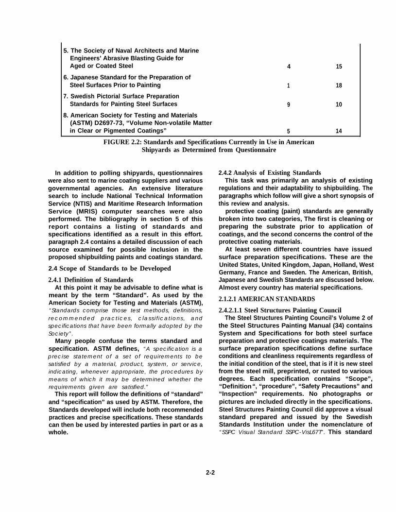
5. The Society of Naval Architects and MarineEngineers’ Abrasive Blasting Guide forAged or Coated Steel 4 15
6. Japanese Standard for the Preparation ofSteel Surfaces Prior to Painting 1 18
7. Swedish Pictorial Surface PreparationStandards for Painting Steel Surfaces 9 10
8. American Society for Testing and Materials(ASTM) D2697-73, “Volume Non-volatile Matterin Clear or Pigmented Coatings” 5 14
FIGURE 2.2: Standards and Specifications Currently in Use in AmericanShipyards as Determined from Questionnaire
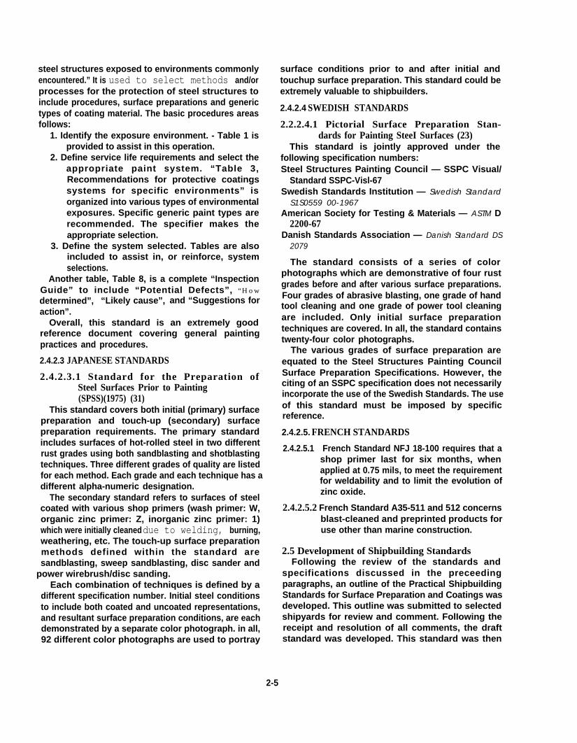
In addition to polling shipyards, questionnaireswere also sent to marine coating suppliers and variousgovernmental agencies. An extensive literaturesearch to include National Technical InformationService (NTIS) and Maritime Research InformationService (MRIS) computer searches were alsoperformed. The bibliography in section 5 of thisreport contains a listing of standards andspecifications identified as a result in this effort.paragraph 2.4 contains a detailed discussion of eachsource examined for possible inclusion in theproposed shipbuilding paints and coatings standard.
2.4 Scope of Standards to be Developed
2.4.1 Definition of StandardsAt this point it may be advisable to define what is
meant by the term “Standard”. As used by theAmerican Society for Testing and Materials (ASTM),“Standards comprise those test methods, definitions,recommended practices, classifications, andspecifications that have been formally adopted by theSociety”.
Many people confuse the terms standard andspecification. ASTM defines, “A specification is aprecise statement of a set of requirements to besatisfied by a material, product, system, or service,indicating, whenever appropriate, the procedures bymeans of which it may be determined whether therequirements given are satisfied.”
This report will follow the definitions of “standard”and “specification” as used by ASTM. Therefore, theStandards developed will include both recommendedpractices and precise specifications. These standardscan then be used by interested parties in part or as awhole.
2-2
2.4.2 Analysis of Existing StandardsThis task was primarily an analysis of existing
regulations and their adaptability to shipbuilding. Theparagraphs which follow will give a short synopsis ofthis review and analysis.
protective coating (paint) standards are generallybroken into two categories, The first is cleaning orpreparing the substrate prior to application ofcoatings, and the second concerns the control of theprotective coating materials.
At least seven different countries have issuedsurface preparation specifications. These are theUnited States, United Kingdom, Japan, Holland, WestGermany, France and Sweden. The American, British,Japanese and Swedish Standards are discussed below.Almost every country has material specifications.
2.1.2.1 AMERICAN STANDARDS
2.4.2.1.1 Steel Structures Painting CouncilThe Steel Structures Painting Council’s Volume 2 of
the Steel Structures Painting Manual (34) containsSystem and Specifications for both steel surfacepreparation and protective coatings materials. Thesurface preparation specifications define surfaceconditions and cleanliness requirements regardless ofthe initial condition of the steel, that is if it is new steelfrom the steel mill, preprinted, or rusted to variousdegrees. Each specification contains “Scope”,“Definition“, “procedure”, “Safety Precautions” and“Inspection” requirements. No photographs orpictures are included directly in the specifications.Steel Structures Painting Council did approve a visualstandard prepared and issued by the SwedishStandards Institution under the nomenclature of“SSPC Visual Standard SSPC-VisL67T”. This standard

will be discussed later. The SSPC standards areprobably the most universally accepted surfacepreparation standard, not only in America, but alsointernationally. The primary limitation of thesespecifications concern the interpretation of theverbiage and the equating of verbiage to visualinterpretation, especially on heavily pitted old steel.These surface preparation standards are presentlybeing rewritten.
The primary change will be a simplification of thewritten specification with many present requirementsbeing moved to a section of the standard called a“Guide”. In the materials area, SSPC published manyprotective coating specifications. Volume 2 of theirmanual contains numerous generic types of paint,ranging from “Oil Based Systems (for WeatherExposed Wire-Brushed Steel)” to “Inorganic Zinc”.Two new specifications for Inorganic Zinc arecurrently being prepared and reviewed. There is somemove afoot to dilute the total zinc contentrequirements of these materials. Hopefully this willnot happen.
SSPC also published a standard method whichconcerns the “Measurement of Dry Paint Thicknesswith Magnetic Gages”, (33). Two types ofmeasurement gages are covered by this specification,namely Pull-Off Gages and Fixed Probe Gages. Themethod takes into account the profile of the substrateand establishes a minimum number of measurementsper given surface area.
2.4.2.1.2 National Association ofCorrosion Engineers
The National Association of Corrosion Engineers(NACE) has issued many standards on surfacepreparation and protective coatings. TheBibliography in Section 6 bares witness to this fact. Inthis author’s opinion, the most valuable specificationsare the Visual Standards for Surface Preparation (39,40, 41). These standards are actual abrasive blastedsteel surfaces prepared to four different degrees ofcleanliness by three different techniques, namelycentrifugally blast cleaned with steel shot,centrifugally blast cleaned with grit, and airblastcleaned with sand abrasives. The primary drawback tothis standard is the fact that relatively new steel wasused to prepare the representation specimens.
Another NACE Standard which deserves mention isRP-01-72 (37), “Surface Preparation of Steel and OtherHard Materials by Water Blasting Prior to Coating orRecrating”. This standard allows the use of highpressure water with and without sand. The degree ofcleanliness after blasting is not defined; however,cleaning rates are given.
NACE Standard RP-01-78, “Design, Fabrication, andSurface Finish of Metal Tanks and Vessels to be Linedfor Chemical Immersion Service” (10) lists design,fabrication and surface finish requirements for tanksand vessels used under severe service conditions topreclude corrosion. One interesting point covered bythis standard concerns sharp edges. Paragraph 4.1states “Sharp edges and fillets shall be ground to asmooth radius of at least 0.3 cm (1/8 inch) with 0.6 cm (1/4inch) preferred”.
NACE also publishes many articles concerning paintmaterials (44, 46,49, 54, 59, 60,61,62, 63).
2.4.2.1.3 The Society of Naval Architects &Marine Engineers (SNAME)
SNAME published an “Abrasive Blasting Guide forAged or Coated Steel Surfaces” (1) which wasprepared by Panel O-23 (Ship’s Paints) of the ShipTechnical Operations Committee in cooperation withthe Naval Applied Science Laboratory and the NavalShip Systems Command.
This Guide includes a series of black and white andcolor photographs depicting both painted andunpainted steel exposed for a time period to a marineenvironment and illustrating the appearance of thesurfaces which result when abrasive blasted to variousgrades. The blasting grades are directly related toSSPC specifications.
Four black and white photographs are included.These photographs are blurred with the areascalculated and depicted approximately as theywould appear following blasting.
Nine color photographs are also included. Eachphotograph is a step-up graduation of surfacecondition before and after blast cleaning. The originalcondition is at the top of the page with increasingdegrees of cleanliness progressing to the bottom ofthe page. Both representations for mild steel and hightensile steel are included. This guide is an excellentsource document, but just as with other pictorialstandards, the one limiting factor is resolution andcolor of photographs.
2.4.2.1.4 American Society for Testingand Materials (ASTM)
Part 27, “Paint-Tests for Formulated Products andApplied Coatings” (2) contains all of the ASTMstandards issued relative to paint. These standardscover test methods, surface preparation, filmthickness measurements, performance evaluationand paint ingredients. Many of these standards wereused to define properties included in the standarddeveloped during this program.
2-3

2.4.2.1.5 OthersMany other American standards exist. The
Bibliography contained in Section 6 of this reportshould be reviewed.
2.4.2.2 BRITISH STANDARDSThe British have issued three primary documents
concerning surface preparation and protectivecoatings. These are discussed below.
2.4.2.2.1 Code of Practice for Cleaningand Preparation of Metal Surfaces(CP3012:1972) (6)
This specification deals mainly with chemical andsolvent cleaning methods and procedures to includeformula and recipes for copper, aluminum, steel,stainless steel, etc. The major sections of thisspecification are listed below:
1. General Cleaning Where No SubsequentCoatings Are to be Applied.
2. Preparation Prior to the Application of SurfaceCoatings
3. Methods (Cleaning and Preparation MethodsReferred to in Sections 1 and 2)
Section 2 is further subdivided into:1. Electrodeposited Metal Coatings2. Electroless Metal Coatings3. Conversion Coatings4. Anodic Oxidation Coatings5. Hot Dipped Coatings6. Sprayed Metal Coatings
7. Diffusion Coatings8. Vitreous and Porcelain Enamel Coatings9. Paint Coatings on Non-Ferrous Metals
Method d, Section 3 concerns abrasive cleaning.This is a very general treatment of blastingrequirements. The recommended grit size is GradeG17 of BS 2451 or larger. It also states that “The processis unsuitable for thin material or where a fine surfacefinish is required.”
2.4.2.2.2 Specification for Surface Finish ofBlast-Cleaned Steel for Painting, BritishStandard 4232:1967 (30)
The following paragraphs are excerpts from theforeword of the specification:
“This British Standard was prepared under theauthority of the Pigments, Paints and VarnishesIndustry Standards Committee at the request of theBritish Association of Corrosion Engineers. It isbased on draft specifications for qualities ofblastcleaning proposed by an expert committee ofthe BACE, to whom due acknowledgement ismade. It is not intended to cover wet methods ofblast cleaning”.
“The quality levels defined in this BritishStandard have been selected so as to be roughlyequivalent to those defined in the internationallystandards of the Steel Structures Painting Counciland the Swedish Standards Organization”.
Figure 2.3 compares each standard.
British Standard Steel Structures Paint Council Swedish Standard
First Quality White Metal (SSPC SP5) SA3
Second Quality Near White Metal (SSPC SPIO) SA2.5
Third Quality Commercial (SSPC SP6) SA2
FIGURE 2.3: Comparison of Various National Abrasive Blasting Standards
The British Standard covers dry abrasive blasting ofnew steel, weathered steel and prior coated steels.The degree, or quality, of the resultant surface isdefined in terms of cleanliness and roughness. It goesonto state that “There are no simple precise means ofmeasuring these characteristics but the first(cleanliness) can be estimated from the appearance ofthe surface and the second (profile) can generally becontrolled with broad limits by the choice of blast-cleaning procedures, notably of the type and grade ofabrasive”. Another very important point made by thespecification is “A first quality finish is unlikely to beattained if the steel is deeply pitted or otherwiseseverely corroded”.
2-4
The selection of abrasives is limited to those whichhave a maximum profile height of 4 roils.
Reference 81, an article written by R.A.N. McKelvieentitled “Steel Cleaning Standards - A Case for TheirReappraisal”, is an excellent write-up on cleaningstandards. Those readers interested in an in-depthdiscussion of cleaning standard should read thisarticle.
2.4.2.2.3 Code of Practice for Protective Coat-ings of Iron and Steel Structures AgainstCorrosion BS 5493:1977 (7)
This British Standard “classifies recommendedmethods of protection against corrosion of iron and
steel structures exposed to environments commonlyencountered.” It is used to select methods and/orprocesses for the protection of steel structures toinclude procedures, surface preparations and generictypes of coating material. The basic procedures areasfollows:
1. Identify the exposure environment. - Table 1 isprovided to assist in this operation.
2. Define service life requirements and select theappropriate paint system. “Table 3,Recommendations for protective coatingssystems for specific environments” isorganized into various types of environmentalexposures. Specific generic paint types arerecommended. The specifier makes theappropriate selection.
3. Define the system selected. Tables are alsoincluded to assist in, or reinforce, systemselections.
Another table, Table 8, is a complete “InspectionGuide” to include “Potential Defects”, “How
determined”, “Likely cause”, and “Suggestions foraction”.
Overall, this standard is an extremely goodreference document covering general paintingpractices and procedures.
2.4.2.3 JAPANESE STANDARDS
2.4.2.3.1 Standard for the Preparation ofSteel Surfaces Prior to Painting(SPSS)(1975) (31)
This standard covers both initial (primary) surfacepreparation and touch-up (secondary) surfacepreparation requirements. The primary standardincludes surfaces of hot-rolled steel in two differentrust grades using both sandblasting and shotblastingtechniques. Three different grades of quality are listedfor each method. Each grade and each technique has adifferent alpha-numeric designation.
The secondary standard refers to surfaces of steelcoated with various shop primers (wash primer: W,organic zinc primer: Z, inorganic zinc primer: 1)which were initially cleaned due to welding, burning,weathering, etc. The touch-up surface preparationmethods defined within the standard aresandblasting, sweep sandblasting, disc sander and
power wirebrush/disc sanding.Each combination of techniques is defined by a
different specification number. Initial steel conditionsto include both coated and uncoated representations,and resultant surface preparation conditions, are eachdemonstrated by a separate color photograph. in all,92 different color photographs are used to portray
surface conditions prior to and after initial andtouchup surface preparation. This standard could beextremely valuable to shipbuilders.
2.4.2.4 SWEDISH STANDARDS
2.2.2.4.1 Pictorial Surface Preparation Stan-dards for Painting SteeI Surfaces (23)
This standard is jointly approved under thefollowing specification numbers:Steel Structures Painting Council — SSPC Visual/
Standard SSPC-Visl-67Swedish Standards Institution — Swedish Standard
S1S0559 00-1967American Society for Testing & Materials — ASTM D
2200-67Danish Standards Association — Danish Standard DS
2079
The standard consists of a series of colorphotographs which are demonstrative of four rustgrades before and after various surface preparations.Four grades of abrasive blasting, one grade of handtool cleaning and one grade of power tool cleaningare included. Only initial surface preparationtechniques are covered. In all, the standard containstwenty-four color photographs.
The various grades of surface preparation areequated to the Steel Structures Painting CouncilSurface Preparation Specifications. However, theciting of an SSPC specification does not necessarilyincorporate the use of the Swedish Standards. The useof this standard must be imposed by specificreference.
2.4.2.5. FRENCH STANDARDS
2.4.2.5.1 French Standard NFJ 18-100 requires that ashop primer last for six months, whenapplied at 0.75 mils, to meet the requirementfor weldability and to limit the evolution ofzinc oxide.
2.4.2.5.2 French Standard A35-511 and 512 concernsblast-cleaned and preprinted products foruse other than marine construction.
2.5 Development of Shipbuilding StandardsFollowing the review of the standards and
specifications discussed in the preceedingparagraphs, an outline of the Practical ShipbuildingStandards for Surface Preparation and Coatings wasdeveloped. This outline was submitted to selectedshipyards for review and comment. FolIowing thereceipt and resolution of all comments, the draftstandard was developed. This standard was then
2-5

submitted to numerous shipyards for review andcomment. These comments were then resolved andthe final standard contained in Section 4 wasdeveloped.
2.6 Development of Paints and Coatings Product/Procedure Data Sheet
The objective of this task was to develop a standardform detailing material properties and applicationdata for marine coatings. It was the intent that thismaterial information sheet should contain provisionsfor information such as generic types of coating,special application procedures and equipment,
minimum surface preparation standards andprocedures, environmental application limits(humidity and temperature) and spread rate.
Existing coating supplier’s product data sheets werereviewed for adequacy and possible format. Apreliminary format was adapted and submitted tomany shipyards for review and comment. Thecomments were evaluated and differences resolved.The data sheet contained in Section 3 of this report isthe result of that effort.
Instructions and sample forms are also included inSection 3.
2-6

SECTION 3Paints and Coatings
product/Procedure Data Sheet
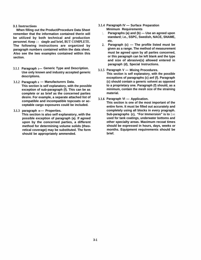
3.1 InstructionsWhen filling out the Product/Procedure Data Sheet
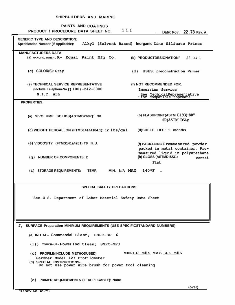
remember that the information contained therin willbe utilized by both technical and productionpersonnel. Keep it simple and brief, BUT COMPLETE.The following instructions are organized byparagraph numbers contained within the data sheet.Also see the two examples contained within thissection.
3.1.1
3.1.2
3.1.3
Paragraph 1— Generic Type and Description.Use only known and industry accepted genericdescriptions.
Paragraph II — Manufacturers Data.This section is self explanatory, with the possibleexception of sub-paragraph (f). This can be ascomplete or as brief as the concerned partiesdesire. For example, a separate attached list ofcompatible and incompatible topcoats or ac-ceptable cargo exposures could be included.
paragraph III — Properties.This section is also self explanatory, with thepossible exception of paragraph (a). If agreedupon by the concerned parties, a differentmethod for determining volume solids (theo-retical coverage) may be substituted. The formshould be appropriately ammended.
3.1.4
1.
2.
3.1.5
3.1.6
Paragraph IV — Surface PreparationMinimum RequirementsParagraphs (a) and (b) — Use an agreed uponstandard; i.e., SSPC, Swedish, NACE, SNAME,etc.Paragraph (c) — The profile listed must begiven as a range. The method of measurementmust be agreed upon by all parties concerned,or this paragraph can be left blank and the typeand size of abrasive(s) allowed entered inparagraph (d), Special Instructions.
Paragraph V — Mixing Procedures.This section is self explanatory, with the possibleexceptions of paragraphs (c) anf (f). Paragraph(c) should contain a generic solvent as opposedto a proprietary one. Paragraph (f) should, as aminimum, contain the mesh size of the strainingmaterial.
Paragraph VI — Application.This section is one of the most important of theentire form. It must be filled out accurately andcompletely using all blocks in every pragraph.Sub-paragraphs (c), “For Immersion” is to beused for tank coatings, underwater bottoms andother specialty areas. Maximum recoat timesshould be expressed in hours, days, weeks ormonths. Equipment requirements should bebrief.
3-1

SHIPBUILDERS AND MARINE
PAINTS AND COATINGSPRODUCT / PROCEDURE DATA SHEET NO.
GENERIC TYPE AND DESCRIPTION:Specification Number (If Applicable):
1. MANUFACTURERS DATA:(a)
(c)
MANUFACTURER: (b) PRODUCT
COLOR(S): (d) USES:
DESIGNATION:
(e) TECHNICAL SERVICE REPRESENTATIVE (f) NOT RECOMMENDED FOR:(Include Telephone No.):
Il. PROPERTIES:
(a) % VOLUME SOLIDS (ASTM D2697):
(c) WEIGHT PER GALLON (FTMS141a 4184.1):
(e) VISCOSITY (FTMS141a 4281):
(g) NUMBER OF COMPONENTS:
(i) STORAGE REQUIREMENTS: TEMP.
(b) FLASH POINT (ASTM D93):OR (ASTM D56):
(d) SHELF LIFE:
(f) PACKAGING:
(h) GLOSS (ASTM D523):
MIN. MAX.
SPECIAL SAFETY PRECAUTIONS:
1V. SURFACE PREPARATION MINIMUM REQUIREMENTS (USE SPECIFIC STANDARD NUMBERS):
(a)
(b)
(c)
(d)
(e)
(OvER)OPS FORM 745 (10-78)
3.2 BLANK PRODUCVPROCEDURE DATA SHEET
INITIAL –
TOUCH–UP –
PROFILE(INCLUDE METHOD USED) –
SPECIAL INSTRUCTIONS –
PRIMER REQUIREMENTS (IF APPLICABLE):
MIN. MAX.
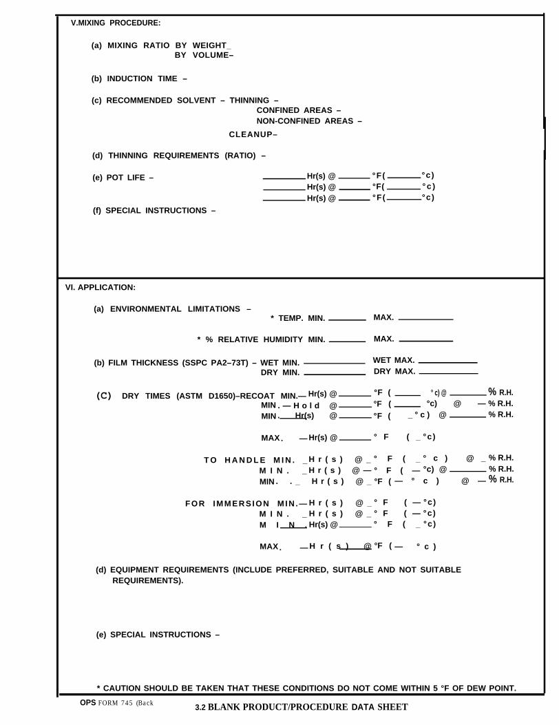
V.MIXING PROCEDURE:
(a) MIXING RATIO BY WEIGHT_BY VOLUME–
(b) INDUCTION TIME –
(c) RECOMMENDED SOLVENT – THINNING –CONFINED AREAS –NON-CONFINED AREAS –
CLEANUP–
(d) THINNING REQUIREMENTS (RATIO) –
(e) POT LIFE – Hr(s) @ °F( °c)Hr(s) @ °F( ° c )Hr(s) @ °F( °c)
(f) SPECIAL INSTRUCTIONS –
VI. APPLICATION:
(a) ENVIRONMENTAL LIMITATIONS –* TEMP. MIN. MAX.
* % RELATIVE HUMIDITY MIN. MAX.
(b) FILM THICKNESS (SSPC PA2–73T) – WET MIN. WET MAX.
DRY MIN. DRY MAX.
(C) DRY TIMES (ASTM D1650)–RECOAT MIN.— Hr(s) @ °F ( ° c) @ % R.H.
MIN . — H o l d @ °F ( °c) @ — % R.H.
MIN . Hr(s) @ °F ( _ ° c ) @ % R.H.
MAX. — Hr(s) @ ° F ( _ °c)
T O H A N D L E M I N . _ H r ( s ) @ _ ° F ( _ ° c ) @ _ % R.H.
M I N . _ H r ( s ) @ — ° F ( — °c) @ % R.H.
MIN . . _ H r ( s ) @ _ °F ( — ° c ) @ — % R.H.
FOR IMMERSION MIN .— H r ( s ) @ _ ° F ( — °c)M I N . _ H r ( s ) @ _ ° F ( — °c)M I N . Hr(s) @ ° F ( _ °c)
MAX H r ( s ) @ °F (. — — ° c )
(d) EQUIPMENT REQUIREMENTS (INCLUDE PREFERRED, SUITABLE AND NOT SUITABLEREQUIREMENTS).
(e) SPECIAL INSTRUCTIONS –
* CAUTION SHOULD BE TAKEN THAT THESE CONDITIONS DO NOT COME WITHIN 5 °F OF DEW POINT.
OPS FORM 745 (Back 3.2 BLANK PRODUCT/PROCEDURE DATA SHEET
SHIPBUILDERS
PAINTS ANDPRODUCT / PROCEDURE DATA SHEET NO. 1-1-1 Date: Nov. 22 .78 Rev. A
AND MARINE
COATINGS - - -
GENERIC TYPE AND DESCRIPTION:Specification Number (If Applicable): Alkyl (Solvent Based) Inorganic Zinc Silicate Primer
MANUFACTURERS DATA:(a) MANUFACTURER : R- Equal Paint Mfg Co. (b) PRODUCTDESIGNATION” 28-DG-1
(c) COLOR(S): Gray (d) USES: preconstruction Primer
(e) TECHNICAL SERVICE REPRESENTATIVE (f) NOT RECOMMENDED FOR:(lnclude TelephoneNo.):( 100)-242-6000 Immersion ServiceN.I.T. ALL See TechicalRepresentative for compatible topcoats
PROPERTIES:
(a) %VOLUME SOLlDS(ASTMD2697): 30 (b) FLASHPOINT(ASTM C193):80”0R(ASTM D56):
(c) WEIGHT PERGALLON (FTMS141a4184.1): 12 lbs/gal (d)SHELF LIFE: 9 months
(e) VISCOSITY (FTMS141a4281):T8 K.U. (f) PACKAGING Premeasured powderpacked in metal container. Pre-measured liquid in polyurethane
(g) NUMBER OF COMPONENTS: 2 (h) GLOSS (ASTMD 5231: contaiFlat
(i) STORAGE REQUIREMENTS: TEMP. MIN. N/A MAX 140°F. —
SPECIAL SAFETY PRECAUTIONS:
See U.S. Department of Labor Material Safety Data Sheet
f, SURFACE Preparation MINIMUM REQUIREMENTS (USE SPECIFICSTANDARD NUMBERS):
(a] INITIAL– Commercial Blast, SSPC-SP 6
(1)) TOUCH-UP- Power Tool Clean; SSPC-SP3
(c) PROFILE(INCLUDE METHODUSED) MIN.1.O mils MAx. 3.5 milS
Gardner Model 123 Profilometer(d) SPECIAL INSTRUCTIONS-.
Do not use power wire brush for power tool cleaning
(e) PRIMER REQIJIREMENTS (IF APPLICABLE): None
(over)

on
F R O M 7 4 5 ( B A C K )
s

SHIPBUILDERS AND MARINE
PAINTS AND COATINGSPRODUCT / PROCEDURE DATA SHEET NO. 2-1-1
> . . . .
GENERIC TYPE AND DESCRIPTION: Epoxy Polyamide
MANUFACTURERS DATA:(a) MANUFACTURER : R-Equal Paint Mfg. Co. (b] PRODUCT DESIGNATION, 40-DX-16
(c) COLOR(S): Red, White, Blue (d) USES: Ballast Tanks
(e) TECHNICAL SERVICE REPRESENTATIVE (f) NOT RECOMMENDED FOR:High temperature service
(a) % VOLUME SOLIDS (ASTM 02697): 50%OR (ASTM D56):
(c) WEIGHT PER GALLON (FTMS141a 4184.1): 12 lbs/gal . (d) SHELF LIFE: 24 months
(e) VISCOSITY (FTMS141a 4281): 12O K.U. (f) PACKAGING,’2 premeasured metalcontainer, one packaged insidethe other
(9) NUMBER OF COMPONENTS: 2 (h) GLOSS (ASTM D523)
Eggshell
(i) STORAGE REQUIREMENTS: TEMP. MIN. O°F MAX. 140° F
SPECIAL SAFETY PRECAUTIONS:
See U.S. Department of Labor Material Safety Data Sheet
SURFACE PREPARATION MINIMUM REQUIREMENTS (USE SPECIFIC STANDARD NUMBERS):
a) INITIAL - Near White Blast, SSPC-SP-1OFor Recoat-First coat must be clean and dry. MechanicallY etch if recoat time
(b) TOUCH-UP has expired.Same as above. Limited power tool cleaning using disc grinders.
(c) PROFILE(INCLUDE METHOD USED)-Gardner Model 123 Profilometer
Do not use power wire brush
(e) PRIMER RETIREMENTS (INAPPLICABLE): Material is self priming. The first coatis considered the prime coat.

(a)
(b)
(c)
MIXING RATlO BY WEIGHT .- 6 lbs component A to 6 lbs of component BBY VOLUME - 1 part component: A to 1 part component B
INDUCTION TIME - 30 minutes
RECOMMENDED SOLVENT-THINNING –CONFINED AREAS - #l SolventNON-CONFINED AREAS– #2 Solvent
CLEANUP– 1 part xylene to 1 part MIBK
(d}
(e)
(f) SPECIAL INSTRUCTIONS –
Keep mixture under constant agitation during application. Strain mixturethrough #30 mesh strainer.
(a) ENVIRONMENTAL LIMITATIONS –● TEMP. MIN.
50% MAx. 90%
(b) FILMTHICKNESS (SSPCPA2–73T) WET MIN. 8.O WET MAX. 14.0DRY MIN. 4.0 DRYMAX. 7.0
MIN . 48 Hr(s) @ 60 °F ( 16 °c) @ 50 % R H
MIN. 77 Hr(s) @ 50 °F (
(d) EQUlPMENT REQUIREMENTS (INCLUDE PREFERRED. SUITABLE AND NOT SUITABLE
Airless Spray -0.021” with 1200-1800 psi fluid pressureBrush and Roller - Minor touch-up only
(e) SPECIAL INSTRUCTIONS - This material is to be applied in three coatsusing alternate color for each coat.

SECTION 4Practical ShipbuildingSurface Preparation
andCoatings Standard

TABLE OF CONTENTS
1.0
2.0
3.04.0
5.0
6.0
7.0
8.0
Scope
Use of the Standard
Applicable DocumentsUse of Paints and Coatings Product/procedure Data Sheets (P/PDS)4.1 Purpose of P/PDS4.2 Procedure for Using P/PDS
Storage
Mixing and Thinning
Surface Preparation7.1 General7.2 Standards
7.2.1 Written Standards7.2.2 Visual Standards
7.3 Ungalvanized Structural Steel7.4 Galvanized Steel and Miscellaneous Non-Ferrous Metals7.5 Plastics and Fiberglass7.6 Aluminum and Aluminum Alloys7.7 Interior Equipment and Components7.8 Chemical Pretreatments7.9 Attention to Detail7.IO Abrasives Used for Abrasive Blast Cleaning Operation
ApplicationGeneral
8.28.38.48.58.68.7
8.88.9
Equipment and ToolsCompressed AirManual Spray ApplicationAutomatic Spray ApplicationBrush ApplicationEnvironmental Considerations8.7.1 Temperature8.7.2 Moisture, Humidity and Dew Point8.7.3 VentilationCover/ProtectionDamage/Repair
8.10 Stripping/Sniping8.11 Film Thickness8.12 Overcoating
9.0 Color
4-i
4-1
4-1
4-1
4-14-14-1
4-1
4-1
4-24-24-24-24-34-34-44-44-44-44-44-54-5
4-54-54-54-54-54-54-64-64-64-64-64-74-74-74-74-8
4-8

10.0 Special Requirements10.1 Keel10.2 Compatibility10.3 Walking and Working Surfaces10.4 Component Items10.5 Calculating Coverages10.6 Timing of Finish Coating”10.7 Antifouling Applications10.8 Optimum Number of Coats10.9 Faying Surfaces
10.9.1 Steel10.9.2 Aluminum10.9.3 Dissimilar Metals10.9.4 Non-Continuous Weld
10.10 Galvanizing10.11 Insulation10.12 Deck Coverings10.13 Items Not to be Coated10.14 Hot Surfaces10.15 Inaccessible Voids
11.0 Protective Coatings System Selection
l2.0 Safety and Pollution Control
13.0 Quality Assurance
14.0 Preconstruction Conference
Appendix 1 — Guide to Protective Coatings (Paint) Selection
Appendix 2 — Glossary of Terms
4-ii
4-84-84-84-84-84-94-94-94-94-94-94-94-94-94-9
4-1o4-1o4-1o4-1o4-1o
4-1o
4-11
4-11
4-13

PROTECTIVE COATINGS (paints)
1.0 ScopeThis document covers the standards governing the
selection of protective coatings (paints) systemsapplied to ships’ structures including appurtenances,attachments and components. Protective coating(paint) systems include surface preparation,application and paint material(s).
2.0 Use of the StandardThis document is an attempt to collect together, in
one standard, all of the requirements necessary tosuccessfully apply protective coatings to ships.Successful application is defined as “the protectivecoating performs as designed, i.e. provides corrosionprotection, cargo protection, increased operatingefficiency, aesthetics, etc., for a defined time period”.This standard is not a specification in the sense ofmandating requirements, but a guide which can beused to prepare contract specifications, goodpractices manuals, industry concensus specificationsand/or quality assurance programs. It can be used inwhole or in part. Each user (shipowner, navalarchitect, shipyard) may have specific requirementswhich exceed or fall below the recommendedrequirement of this document.
3.0
4.0
Applicable Documents — See Bibliography inSection 5.1
Use of Paints and Coatings Product/ProcedureData Sheet(s) (P/PDS).
4.1 Purpose of P/PDSThe P/PDS is a two-page data sheet whichcontains both technical and applicationrequirements of a specific protectivecoating. It can be used by engineers to selectcandidate coatings which meet contractrequirements, by production managementto evaluate potential production problems,by quality control personnel to checkattributes and by craft supervision in theactual coatings application.
4.2 Procedure for Using P/PDSDuring the negotiation stage between
shipyard and coating supplier(s), and priorto protective coatings material selection,each material supplier shall submit“Shipbuilding and Marine Paints andCoatings Product/Procedure Data Sheets”to the shipbuilder/construction firm foreach protective coating proposed for use ona given contract. The shipbuilder.construe-tion firm will review the submitted
procedures to determine compatibility withthe governing contract specification and themanufacturing facility. After materialselection, the f inalized, approvedProduct/Procedure Data Sheet(s) becomethe basic document governing the surfacepreparation and application of each specificprotective coating.
5.0 Storage
5.1
5.2
5.3
All protective coatings shall be stored insuch a manner as to preclude eradication oflabels/markings and subsequent loss ofidentification and/or batch number. Speci-fic storage requirements and shelf life arecovered in Section III (i) of Product/proce-dure Data Sheet.Procedures shall be established to ensurethat the oldest stock material is used prior tonewer/fresher material; “first manufac-tured-first used”. Containers should bemarked with batch number and date ofmanufacture expressed as easy-to-readmonth, date and year. This requirement is inaddition to any date code that maybe used.Labels and markings shall be firmly attachedto containers and designed to withstandshort periods of outside storage without lossof identification.
6.0 Mixing and Thinning
6.1 All materials shall be mixed and/or thinned(reduced) in strict accordance with SectionV of the pertinent Product/Procedure DataSheet.
6.2 [n addition, the following minimum proceduresshall be followed.
6.2.1
6.2.2
6.2.3
Where a skin has formed in the container,the skin shall be cut loose from the sides ofthe container, removed, and discarded. ifsuch skins are thick enough to have apractical effect on the composition andquality of the paint, the paint shall not beused. If a question as to acceptabilitypersists, the coatings supplier shall beconsulted.All ingredients in any container of paint shallbe thoroughly mixed before use.protective coatings mixed in the originalcontainer shall not be transferred until allsettled pigment is incorporated into thevehicle. This does not imply that part of the
4-1

6.2.4
6.2.5
6.2.6
6.2.7
6.2.8
6.2.9
vehicle cannot be poured off temporarily tosimplify the mixing.Mixing shall be by mechanical methods,except that hand mixing shall be permittedfor containers up to one (1) gallon in size.Protective coatings shall NOT be mixed orkept in suspension by means of an air streambubbling under the paint surface.All protective coatings shall be strained aftermixing. Care shall be taken with suchcoatings as inorganic zinc and aluminum toinsure that the sieve size of the strainer is notso small as to reduce the amount of pigmentin the strained mixture.Dry pigments which are separately pack-aged shall be mixed into protective coatingsin such a manner that they are uniformlyblended and all particles of the dry powderare wetted by the vehicle.Protective coatings which do not have alimited pot life, or do not deteriorate onstanding, may be mixed at any time beforeusing. Protective coatings shall not remain inspray pots, painters’ buckets, etc., overnight,but like material shall be gathered into acontainer and remixed before use.Catalysts, curing agents or hardeners whichare separately packaged shall be added tothe base paint only after the latter has beenthoroughly mixed. The proper volume ofthe curing agent shall then be slowly pouredinto the required volume of base withconstant agitation. If required, allow for theinduction time recommended by thecoating supplier as listed on the Product/Procedure Data Sheet.
1
6.2.10
6.2.11
Do NOT pour off the liquid which hasseparated from the pigment and then addthe curing agent to the settled pigment toaid mixing, The mixture shall be used withinthe time interval specified on the Product/Procedure Data Sheet.Zinc rich, and other types of material whichhave a tendency to settle rapidly, shall becontinually mixed during application. SeePoduct/Procedure Data Sheet for specialinstructions.
7.0 SURFACE PREPARATION7.1 General
The primary consideration of any method, proce-dure, or standard concerning surface preparation isthat the surface is thoroughly cleaned of any materialwhich will be conducive to premature failure of theprotective coating and a suitable “tooth” is providedfor proper paint adhesions. The surface preparationmethod/standard shall allow for the removal ofsufficient deleterious matter so that the type of primer(or coating) specified can wet the surface enough todevelop adequate adhesion and at the same timeeliminate contaminants which lead to prematurecoatings failure. The necessary kind and degree ofsurface preparation are dependent upon the sub-strate material and its condition, the nature of theprime coat, the topcoats to be applied, and the serviceconditions and performance requirements of thecoating system. It is, therefore, appropriate that thesurface preparation requirements shall be specified indetail.7.2 STANDARDS
7.2.1 Written StandardsWhere the following processes are speci-fied, the noted standard shall apply: -
I British SwedishProcess Standard Standard SSPC NACE
Solvent Cleaning
Hand Tool Cleaning
Power Tool Cleaning
White Metal Blast Cleaning
Commercial Blast Cleaning
Brush-Off Blast Cleaning
Near-White Blast Cleaning
Pickling
SSPC-SP 1-63
SSPC-SP 2-63
SSPC-SP 3-63
First Quality SA3 SSPC-SP 5-63 No. 1
Third Quality SA2 SSPC-SP 6-63 No. 3
SSPC-SP 7-63 No. 4
Second Quality SA25 SSPC-SP 10-63T No. 2
SSPC-SP 8-63T
4-2

7.2.2 Visual StandardsWhere specified on the Product/ProcedureData Sheet, one or more of the followingstandards should apply:
I TITLE STANDARD
pictorial Surface Preparation Standards SSPC-Vis-l-67Tfor Painting Steel Structurals(Known as the Swedish Standards).
Visual Standard for Surfaces of New NACE Standard TM-01-70Steel Airblast Cleaned with Sand Abrasive.
Visual Standard for Surfaces of New NACE Standard TM-01-75Steel Centrifugally Blast Cleaned withSteel Grit.
Visual Standard for Surfaces of New Steel NACE Standard TM-01-75Steel Centrifugally Blast Cleaned with Steel Shot.
Standard for the Preparation of Steel Surface JSRA-1975prior to Painting (Japanese Standard).
Abrasive Blasting Guide for Aged or SNAME T & R BulletinCoated Steel Surfaces No. 4-9
As an alternate to one of the standards listed above,and if agreed upon by the concerned parties, astandard blast coupon demonstrating the abrasiveused and the resulting appearance of the surface shallbe created. Minimum size should be 6“ x 6“. This canbe accomplished during the pre-construction confer-ence, held after protective coating selection but priorto actual construction start. A representative steelpanel(s) shall be abrasive blasted to a conditionagreed upon by the parties present (Shipyard, Owner,Supplier) as being representative of the specified blastfinish(es). This panel(s) will then be protected fromrusting either by encapsulation in a clean plastic resinor protected by other means such as rust preventivepaper.
7.3 Ungalvanized Structural Steel7.3.I Steel shall be sound and free from such
segregation, cracks, laminations or surfaceflaws that may preclude successful protec-tive coating performance. Surface lamina-tion, shelling, cracks, crevices, inclusionsand surface flaws shall be removed prior tosurface preparation and coating. Burrs shallbe removed and sharp edges ground to a1/16” radius prior to coatings application.For extremely severe service areas such aschemical tanks, sharp edges shall beground to a 1/8” radius.
4-3
7.3.2
7.3.3
73.4
Initially, all ungalvanized structural steelshall be abrasive blast cleaned to a surfacepreparation standard specified in therespective Product/Procedure Data Sheetfor the particular protective coating (paint)which is specified to be applied over thesubstrate in question. As a minimum, severeservice areas such as exterior exposed toweather, tanks and other defined areas, shallbe abrasive blasted to Near White BlastCleaning (SSPC-SP 10-63 T). All otherstructural steel shall be abrasive blasted to aminimum of Commercial Blast Cleaning(SSPC-SP6-63) or pickled (SSPC-SP8-63).Procedures, equipment requirements, andsurface preparation standards for touch-upshall be defined in Section IV (b) of theProduct/Procedure Data Sheet (s). Surfacepreparation and coating shall be so pro-grammed that detrimental amounts of dust,or other contaminants, do not fall on cleanlyprepared surfaces or on wet, newly paintedsurfaces. Surfaces not intended to be coatedshall be suitably protected from the effectsof surface preparation and coating opera-tions.For interiors of lube oil tanks includingstiffeners, pickling or Commercial Blast
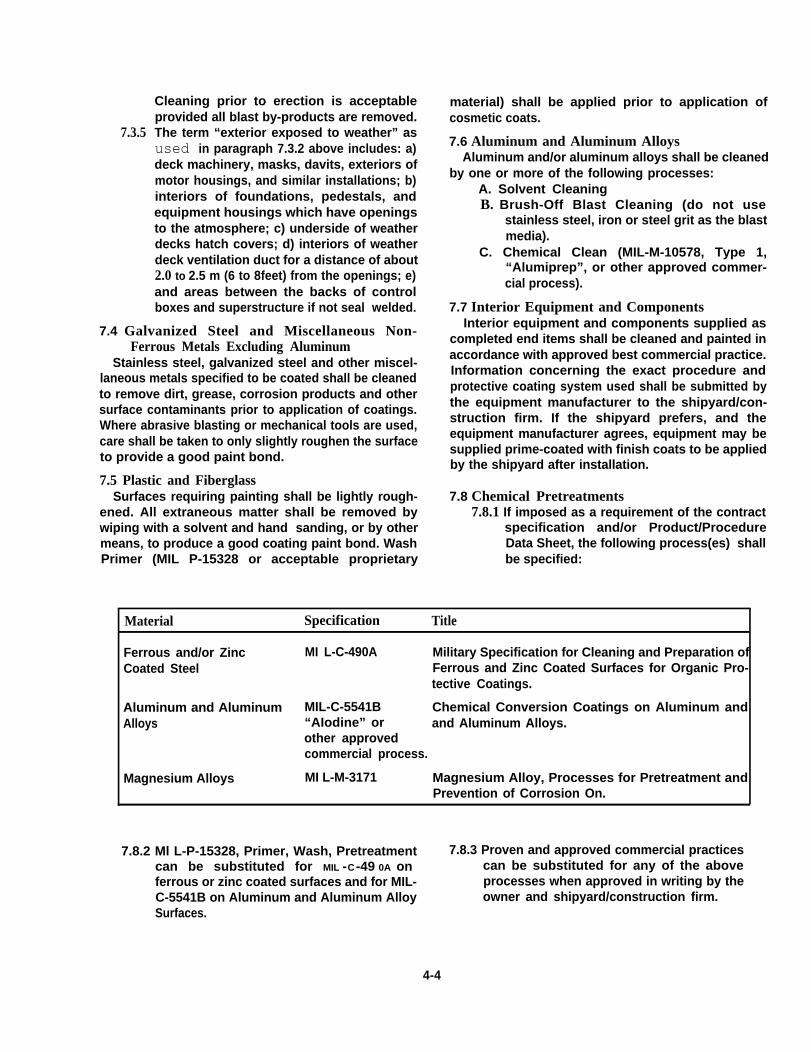
7.3.5
Cleaning prior to erection is acceptableprovided all blast by-products are removed.The term “exterior exposed to weather” asused in paragraph 7.3.2 above includes: a)deck machinery, masks, davits, exteriors ofmotor housings, and similar installations; b)interiors of foundations, pedestals, andequipment housings which have openingsto the atmosphere; c) underside of weatherdecks hatch covers; d) interiors of weatherdeck ventilation duct for a distance of about2.0 to 2.5 m (6 to 8feet) from the openings; e)and areas between the backs of controlboxes and superstructure if not seal welded.
7.4 Galvanized Steel and Miscellaneous Non-Ferrous Metals Excluding Aluminum
Stainless steel, galvanized steel and other miscel-laneous metals specified to be coated shall be cleanedto remove dirt, grease, corrosion products and othersurface contaminants prior to application of coatings.Where abrasive blasting or mechanical tools are used,care shall be taken to only slightly roughen the surfaceto provide a good paint bond.
7.5 Plastic and FiberglassSurfaces requiring painting shall be lightly rough-
ened. All extraneous matter shall be removed bywiping with a solvent and hand sanding, or by othermeans, to produce a good coating paint bond. WashPrimer (MIL P-15328 or acceptable proprietary
material) shall be applied prior to application ofcosmetic coats.
7.6 Aluminum and Aluminum AlloysAluminum and/or aluminum alloys shall be cleaned
by one or more of the following processes:A. Solvent CleaningB. Brush-Off Blast Cleaning (do not use
stainless steel, iron or steel grit as the blastmedia).
C. Chemical Clean (MIL-M-10578, Type 1,“Alumiprep”, or other approved commer-cial process).
7.7 Interior Equipment and ComponentsInterior equipment and components supplied as
completed end items shall be cleaned and painted inaccordance with approved best commercial practice.Information concerning the exact procedure andprotective coating system used shall be submitted bythe equipment manufacturer to the shipyard/con-struction firm. If the shipyard prefers, and theequipment manufacturer agrees, equipment may besupplied prime-coated with finish coats to be appliedby the shipyard after installation.
7.8 Chemical Pretreatments7.8.1 If imposed as a requirement of the contract
specification and/or Product/ProcedureData Sheet, the following process(es) shallbe specified:
Material Specification Title
Ferrous and/or Zinc MI L-C-490A Military Specification for Cleaning and Preparation ofCoated Steel Ferrous and Zinc Coated Surfaces for Organic Pro-
tective Coatings.
Aluminum and Aluminum MIL-C-5541B Chemical Conversion Coatings on Aluminum andAlloys “AIodine” or and Aluminum Alloys.
other approvedcommercial process.
Magnesium Alloys MI L-M-3171 Magnesium Alloy, Processes for Pretreatment andPrevention of Corrosion On.
7.8.2 Ml L-P-15328, Primer, Wash, Pretreatment 7.8.3 Proven and approved commercial practicescan be substituted for MIL -C -49 0A on can be substituted for any of the aboveferrous or zinc coated surfaces and for MIL- processes when approved in writing by theC-5541B on Aluminum and Aluminum Alloy owner and shipyard/construction firm.Surfaces.
4-4
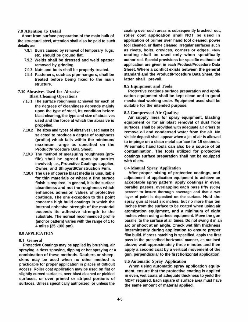
7.9 Attention to DetailApart from surface preparation of the main bulk of
the structural steel, attention shall also be paid to suchdetails as:
7.9.1
7.9.2
7.9.37.9.4
Burrs caused by removal of temporary lugs,etc. should be ground flat.Welds shall be dressed and weld spatterremoved by grinding.Nuts and bolts shall be properly treated.Fasteners, such as pipe-hangers, shall betreated before being fixed to the mainstructure.
7.10 Abrasives Used for AbrasiveBlast Cleaning Operations
7.10.1
7.10.2
7.10.3
7.10.4
The surface roughness achieved for each ofthe degrees of cleanliness depends mainlyupon the type of steel, its condition beforeblast-cleaning, the type and size of abrasivesused and the force at which the abrasive ispropelled.The sizes and types of abrasives used must beselected to produce a degree of roughness(profile) which falls within the minimum/maximum range as specified on theProduct/Procedure Data Sheet.The method of measuring roughness (pro-file) shall be agreed upon by partiesinvolved; i.e., Protective Coatings supplier,Owner, and Shipyard/Construction Firm.The use of coarse blast media is unsuitablefor thin materials or where a fine suracefinish is required. In general, it is the surfacecleanliness and not the roughness whichenhances adhesion values of protectivecoatings. The one exception to this pointconcerns high build coatings in which theinternal cohesive strength of the materialexceeds its adhesive strength to thesubstrate. The normal recommended profile(anchor pattern) varies with the range of 1 to4 milss (25 -100 pm).
8.0 APPLICATION
8.1 GeneralProtective Coatings may be applied by brushing, air
spraying, airless spraying, dipping or hot spraying or acombination of these methods. Daubers or sheep-skins may be used when no other method ispracticable for proper application in places of difficultaccess. Roller coat application may be used on flat orslightly curved surfaces, over blast cleaned or pickledsurfaces, or over primed or striped portions ofsurfaces. Unless specifically authorized, or unless the
coating over such areas is subsequently brushed out,roller coat application shall NOT be used inapplication of primer over hand tool cleaned, powertool cleaned, or flame cleaned irregular surfaces suchas rivets, bolts, crevices, corners or edges. Flowcoating shall be used only when specificallyauthorized. Special provisions for specific methods ofapplication are given in each Product/Procedure DataSheet. Where a conflict exists between the generalstandard and the Product/Procedure Data Sheet, thelatter shall prevail.
8.2 Equipment and ToolsProtective coatings surface preparation and appli-
cation equipment shall be kept clean and in goodmechanical working order. Equipment used shall besuitable for the intended purpose.
8.3 Compressed Air Quality;Air supply lines for spray equipment, blasting
equipment or for air blast removal of dust fromsurfaces, shall be provided with adequate air driers toremove oil and condensed water from the air. Novisible deposit shall appear when a jet of air is allowedto impinge on a clean metal surface for 15 seconds.Pneumatic hand tools can also be a source of oilcontamination. The tools utilized for protectivecoatings surface preparation shall not be equippedwith oilers.
8.4 Manual Spray ApplicationAfter proper mixing of protective coatings, and
adjustment of application equipment to achieve anacceptable spray pattern, apply coatings in even,parallel passes, overlapping each pass fifty (5o%)percent to insure thorough coverage and that a wetlayer of paint is deposited on the surface. Hold thespray gun at least six inches, but no more than teninches from the surface to be coated when using airatomization equipment, and a minimum of eightinches when using airless equipment. Move the gunparallel to the surface at all times. Do not swing it in anarc or shoot at an angle. Check wet film thicknessintermittently during application to ensure properfilm build. If cross hatching is specified, apply the firstpass in the prescribed horizontal manner, as outlinedabove; wait approximately three minutes and thenapply a second coat by a vertical movement of thegun, perpendicular to the first horizontal application.
8.5 Automatic Spray ApplicationWhen using automatic spray application equip-
ment, ensure that the protective coating is appliedin even, wet coats of adequate thickness to yield theMDFT required. Each square of surface area must havethe same amount of material applied.
4-5
8.6 Brush ApplicationThe brushing shall be done so that a smooth coat as
nearly uniform in thickness as possible, is obtained.This usually may best be accomplished by applying theprotective coating in short strokes, depositing uni-form amountsof coating in each stroke, brushing thecoating into all surface irregularities, and finallysmoothing or leveling the coating film with longerstrokes at about right angles to the direction of thefirst strokes, allowing only enough of the tip of thebristles to drag in the coating film to smooth the filmwithout leaving deep or detrimental brush marks.
8.7 Environmental Considerations8.7.1 Temperature
The minimum and maximum temperatures
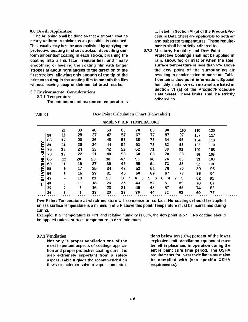
8.7.2
as listed in Section VI (a) of the Product/Pro-cedure Data Sheet are applicable to both airand substrate temperatures. These require-ments shall be strictly adhered to.Moisture, Humidity and Dew PointProtective Coatings shall not be applied inrain, snow, fog or mist or when the steelsurface temperature is less than 5°F abovethe dew point of the surrounding airresulting in condensation of moisture. TableI contains dew point information. Specialhumidity limits for each material are listed inSection VI (a) of the Product/ProcedureData Sheet. These limits shall be strictlyadhered to.
TABLE I Dew Point Calculation Chart (Fahrenheit)
AMBlENT AIR TEMPERATURE°
20 30 40 50 60 70 80 90 100 110 12090 18 28 37 47 57 67 77 87 97 107 11785 17 26 36 45 55 65 75 84 95 104 11380 16 25 34 44 54 63 73 82 93 102 11075 15 24 33 42 52 62 71 80 91 100 10870 13 22 31 40 50 60 68 78 88 96 10565 12 20 29 38 47 56 66 76 85 93 10360 11 19 27 36 45 55 64 73 83 92 10155 9 17 25 34 43 53 61 70 80 89 9850 6 15 23 31 40 50 59 67 77 86 9445 4 13 21 29 3 7 4 5 5 6 6 4 7 3 82 9140 1 11 18 26 35 43 52 61 69 78 8735 2 8 16 23 31 40 48 57 65 74 8330 6 4 13 20 28 36 44 52 61 69 77. . . . . . . . . . . . . . . . . . . . . . . . . . . . . . . . . . . . . . . . . . . . . . . . . . . . . . . . . . . . . . . . . . . . . . . . . . . . . . . . . . . . . . . . .
Dew Point: Temperature at which moisture will condense on surface. No coatings should be appliedunless surface temperature is a minimum of 5°F above this point. Temperature must be maintained duringcuring.Example: If air temperature is 70°F and relative humidity is 65%, the dew point is 57°F. No coating shouldbe applied unless surface temperature is 62°F minimum.
8.7.3 Ventilation tions below ten (10%) percent of the lowerNot only is proper ventilation one of the explosive limit. Ventilation equipment mustmost important aspects of coatings applica- be left in place and in operation during thetion and proper protective coating cure, it is entire paint cure time period. The OSHAalso extremely important from a safety requirements for lower toxic limits must alsoaspect. Table II gives the recommended air be complied with (see specific OSHAflows to maintain solvent vapor concentra- requirements).
4-6
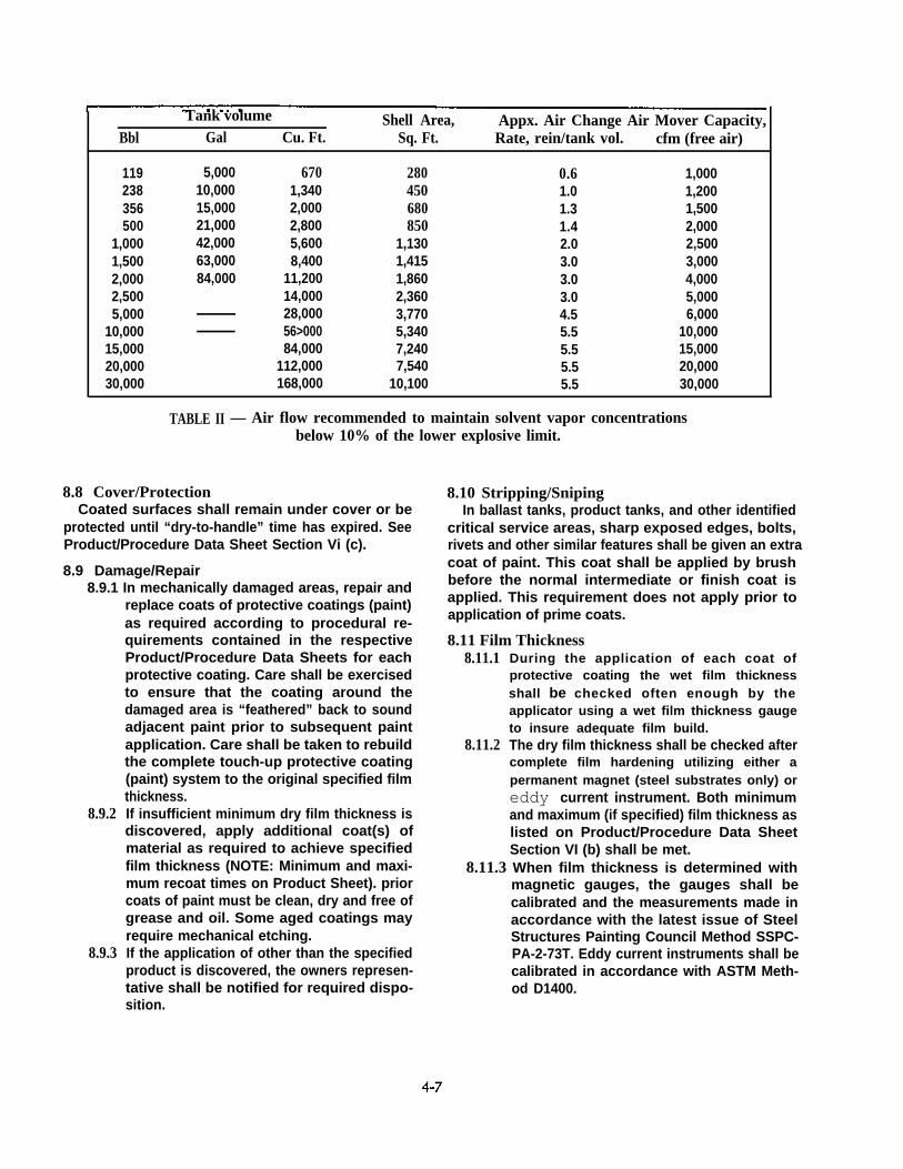
Tank volume Shell Area, Appx. Air Change Air Mover Capacity,Bbl Gal Cu. Ft. Sq. Ft. Rate, rein/tank vol. cfm (free air)
119238356500
1,0001,5002,0002,5005,000
10,00015,00020,00030,000
5,00010,00015,00021,00042,00063,00084,000
6701,3402,0002,8005,6008,400
11,20014,00028,00056>00084,000
112,000168,000
280450680850
1,1301,4151,8602,3603,7705,3407,2407,540
10,100
0.61.01.31.42.03.03.03.04.55.55.55.55.5
1,0001,2001,5002,0002,5003,0004,0005,0006,000
10,00015,00020,00030,000
TABLE II — Air flow recommended to maintain solvent vapor concentrationsbelow 10% of the lower explosive limit.
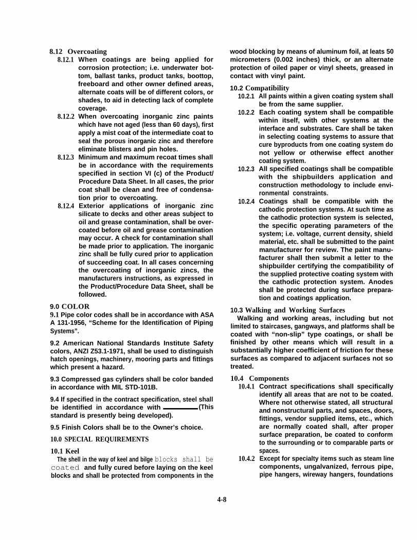
8.8 Cover/ProtectionCoated surfaces shall remain under cover or be
protected until “dry-to-handle” time has expired. SeeProduct/Procedure Data Sheet Section Vi (c).
8.9 Damage/Repair8.9.1 In mechanically damaged areas, repair and
replace coats of protective coatings (paint)as required according to procedural re-quirements contained in the respectiveProduct/Procedure Data Sheets for eachprotective coating. Care shall be exercisedto ensure that the coating around thedamaged area is “feathered” back to soundadjacent paint prior to subsequent paintapplication. Care shall be taken to rebuildthe complete touch-up protective coating(paint) system to the original specified filmthickness.
8.9.2
8.9.3
If insufficient minimum dry film thickness isdiscovered, apply additional coat(s) ofmaterial as required to achieve specifiedfilm thickness (NOTE: Minimum and maxi-mum recoat times on Product Sheet). priorcoats of paint must be clean, dry and free ofgrease and oil. Some aged coatings mayrequire mechanical etching.If the application of other than the specifiedproduct is discovered, the owners represen-tative shall be notified for required dispo-sition.
8.10 Stripping/SnipingIn ballast tanks, product tanks, and other identified
critical service areas, sharp exposed edges, bolts,rivets and other similar features shall be given an extracoat of paint. This coat shall be applied by brushbefore the normal intermediate or finish coat isapplied. This requirement does not apply prior toapplication of prime coats.
8.11 Film Thickness8.11.1
8.11.2
During the application of each coat ofprotective coating the wet film thicknessshall be checked often enough by theapplicator using a wet film thickness gaugeto insure adequate film build.The dry film thickness shall be checked aftercomplete film hardening utilizing either apermanent magnet (steel substrates only) oreddy current instrument. Both minimumand maximum (if specified) film thickness aslisted on Product/Procedure Data SheetSection VI (b) shall be met.
8.11.3 When film thickness is determined withmagnetic gauges, the gauges shall becalibrated and the measurements made inaccordance with the latest issue of SteelStructures Painting Council Method SSPC-PA-2-73T. Eddy current instruments shall becalibrated in accordance with ASTM Meth-od D1400.
8.12 Overcoating8.12.1
8.12.2
8.12.3
8.12.4
When coatings are being applied forcorrosion protection; i.e. underwater bot-tom, ballast tanks, product tanks, boottop,freeboard and other owner defined areas,alternate coats will be of different colors, orshades, to aid in detecting lack of completecoverage.When overcoating inorganic zinc paintswhich have not aged (less than 60 days), firstapply a mist coat of the intermediate coat toseal the porous inorganic zinc and thereforeeliminate blisters and pin holes.Minimum and maximum recoat times shallbe in accordance with the requirementsspecified in section VI (c) of the Product/Procedure Data Sheet. In all cases, the priorcoat shall be clean and free of condensa-tion prior to overcoating.Exterior applications of inorganic zinc. .silicate to decks and other areas subject tooil and grease contamination, shall be over-coated before oil and grease contaminationmay occur. A check for contamination shallbe made prior to application. The inorganiczinc shall be fully cured prior to applicationof succeeding coat. In all cases concerningthe overcoating of inorganic zincs, themanufacturers instructions, as expressed inthe Product/Procedure Data Sheet, shall befollowed.
9.0 COLOR9.1 Pipe color codes shall be in accordance with ASAA 131-1956, “Scheme for the Identification of PipingSystems”.
9.2 American National Standards Institute Safetycolors, ANZI Z53.1-1971, shall be used to distinguishhatch openings, machinery, mooring parts and fittingswhich present a hazard.
9.3 Compressed gas cylinders shall be color bandedin accordance with MIL STD-101B.
9.4 If specified in the contract specification, steel shallbe identified in accordance with (Thisstandard is presently being developed).
9.5 Finish Colors shall be to the Owner’s choice.
10.0 SPECIAL REQUIREMENTS
10.1 KeelThe shell in the way of keel and bilge blocks shall be
coated and fully cured before laying on the keelblocks and shall be protected from components in the
wood blocking by means of aluminum foil, at leats 50micrometers (0.002 inches) thick, or an alternateprotection of oiled paper or vinyl sheets, greased incontact with vinyl paint.
10.2 Compatibility10.2.1
10.2.2
10.2.3
10.2.4
All paints within a given coating system shallbe from the same supplier.Each coating system shall be compatiblewithin itself, with other systems at theinterface and substrates. Care shall be takenin selecting coating systems to assure thatcure byproducts from one coating system donot yellow or otherwise effect anothercoating system.All specified coatings shall be compatiblewith the shipbuilders application andconstruction methodology to include envi-ronmental constraints.Coatings shall be compatible with thecathodic protection systems. At such time asthe cathodic protection system is selected,the specific operating parameters of thesystem; i.e. voltage, current density, shieldmaterial, etc. shall be submitted to the paintmanufacturer for review. The paint manu-facturer shall then submit a letter to theshipbuilder certifying the compatibility ofthe supplied protective coating system withthe cathodic protection system. Anodesshall be protected during surface prepara-tion and coatings application.
10.3 Walking and Working SurfacesWalking and working areas, including but not
limited to staircases, gangways, and platforms shall becoated with “non-slip” type coatings, or shall befinished by other means which will result in asubstantially higher coefficient of friction for thesesurfaces as compared to adjacent surfaces not sotreated.
10.4 Components10.4.1
10.4.2
4-8
Contract specifications shall specificallyidentify all areas that are not to be coated.Where not otherwise stated, all structuraland nonstructural parts, and spaces, doors,fittings, vendor supplied items, etc., whichare normally coated shall, after propersurface preparation, be coated to conformto the surrounding or to comparable parts orspaces.Except for specialty items such as steam linecomponents, ungalvanized, ferrous pipe,pipe hangers, wireway hangers, foundations
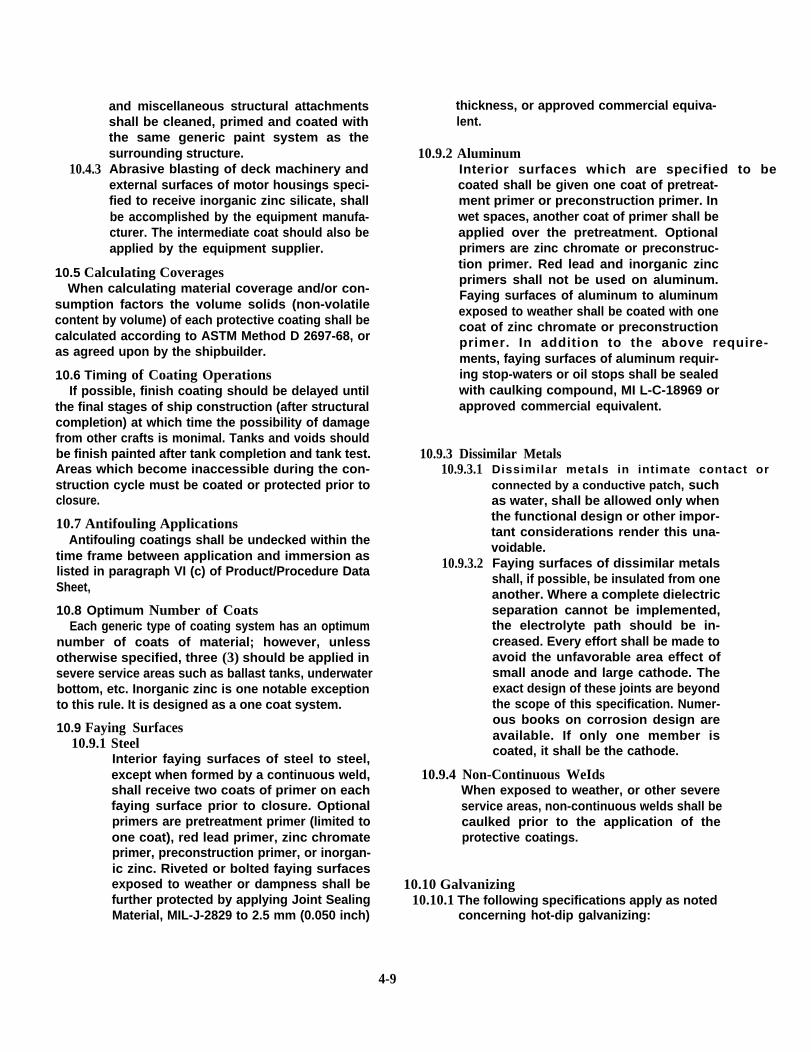
10.4.3
and miscellaneous structural attachmentsshall be cleaned, primed and coated withthe same generic paint system as thesurrounding structure.Abrasive blasting of deck machinery andexternal surfaces of motor housings speci-fied to receive inorganic zinc silicate, shallbe accomplished by the equipment manufa-cturer. The intermediate coat should also beapplied by the equipment supplier.
10.5 Calculating CoveragesWhen calculating material coverage and/or con-
sumption factors the volume solids (non-volatilecontent by volume) of each protective coating shall becalculated according to ASTM Method D 2697-68, oras agreed upon by the shipbuilder.
10.6 Timing of Coating OperationsIf possible, finish coating should be delayed until
the final stages of ship construction (after structuralcompletion) at which time the possibility of damagefrom other crafts is monimal. Tanks and voids shouldbe finish painted after tank completion and tank test.Areas which become inaccessible during the con-struction cycle must be coated or protected prior toclosure.
10.7 Antifouling ApplicationsAntifouling coatings shall be undecked within the
time frame between application and immersion aslisted in paragraph VI (c) of Product/Procedure DataSheet,
10.8 Optimum Number of CoatsEach generic type of coating system has an optimum
number of coats of material; however, unlessotherwise specified, three (3) should be applied insevere service areas such as ballast tanks, underwaterbottom, etc. Inorganic zinc is one notable exceptionto this rule. It is designed as a one coat system.
10.9 Faying Surfaces10.9.1 Steel
Interior faying surfaces of steel to steel,except when formed by a continuous weld,shall receive two coats of primer on eachfaying surface prior to closure. Optionalprimers are pretreatment primer (limited toone coat), red lead primer, zinc chromateprimer, preconstruction primer, or inorgan-ic zinc. Riveted or bolted faying surfacesexposed to weather or dampness shall befurther protected by applying Joint SealingMaterial, MIL-J-2829 to 2.5 mm (0.050 inch)
thickness, or approved commercial equiva-lent.
10.9.2 AluminumInterior surfaces which are specified to becoated shall be given one coat of pretreat-ment primer or preconstruction primer. Inwet spaces, another coat of primer shall beapplied over the pretreatment. Optionalprimers are zinc chromate or preconstruc-tion primer. Red lead and inorganic zincprimers shall not be used on aluminum.Faying surfaces of aluminum to aluminumexposed to weather shall be coated with onecoat of zinc chromate or preconstructionprimer. In addition to the above require- ments, faying surfaces of aluminum requir-ing stop-waters or oil stops shall be sealedwith caulking compound, MI L-C-18969 orapproved commercial equivalent.
10.9.3 Dissimilar Metals10.9.3.1
10.9.3.2
Dissimilar metals in intimate contact or connected by a conductive patch, suchas water, shall be allowed only whenthe functional design or other impor-tant considerations render this una-voidable.Faying surfaces of dissimilar metalsshall, if possible, be insulated from oneanother. Where a complete dielectricseparation cannot be implemented,the electrolyte path should be in-creased. Every effort shall be made toavoid the unfavorable area effect ofsmall anode and large cathode. Theexact design of these joints are beyondthe scope of this specification. Numer-ous books on corrosion design areavailable. If only one member iscoated, it shall be the cathode.
10.9.4 Non-Continuous WeIdsWhen exposed to weather, or other severeservice areas, non-continuous welds shall becaulked prior to the application of theprotective coatings.
10.10 Galvanizing10.10.1 The following specifications apply as noted
concerning hot-dip galvanizing:
4-9

10.10.2
10.10.3
10.10.4
Item Specification
welded and Seamless Steel Pipe ASTM A 53-72a
Zinc (Hot-Galvanized) Coatings on Products ASTM A123-73Fabricated from Rolled, pressed & Forged Steel Shapes,Plates, Bars & Strip
Zinc Coatings (Hot-Dip) on Iron and Steel Hardware ASTM A153-73
In addition to the above listed specificrequirements, the following two (2) generalrequirements shall also apply.A. ASTM A385-62, “Providing High Quality
Zinc Coatings (Hot-Dip) on AssembledA. Products”.B. ASTM A386-73 “Zinc Coating (Hot-Dip)
on Assembled Steel Products.Damaged galvanized surfaces shall becleaned and sprayed with 0.67 kg of zincmetal per square meter (2 oz. per sq. foot),or 85 micrometers (3.4 roils) thick, or berepaired using “Cold Galvanized RepairPaint”, Ml L-P-21035, “Galvacon”, “Gal vex”or other approved commercial material.Where possible, ferrous piping or othersmall steel fabrications required to begalvanized shall preferably be galvanizedafter fabrication.
10.11 InsulationTwo coats of primer shall be applied in way of
insulation.
10.12 Deck CoveringsDeck coverings shall be in accordance with the
deck covering specifications and will not beaddressed in this specification.
10.13 Items not to be CoatedThe following items shall not be coated:A.
B.
c .D.
E.
F.G.H.
Bell pulls, sheaves, annunciator chains and othermechanical communication devices.Composition heads and outer surfaces ofcondensers.Exposed parts of machinery.Glands, stems, yokes, toggle gear and allmachined external parts of valves.Heat exchange surfaces of heating or coolingequipment.Anodesjoint faces of gaskets and packing surfaces.Lubricating gear such as oil holes, oil or greasecups, lubricators, and surfaces of reciprocatingengines and pumps.
J. Nameplates.K. Rubber resilient elements of isolation mounts.L. Sliding feet.
M. SpringsN. Threaded partsO. Turbine casing joints
10.14 Hot SurfacesTT-P-28d or commercial equivalent Heat Resistant
Paint shall be applied to surfaces which are designedfor elevated temperature service up to 650°C (1200°F).
10.15 Inaccessible VoidsInaccessible voids shall be coated with Rust
Preventative Compound (MIL-C-16173D) (Grade 1),or commercial equivalent, by filling and draining; bythe application of foamed-in-place polyurethane(two pounds per cubic foot density) or approvedcommercial process.
11.0 PROTECTWE COATINGS SYSTEMS SELECTION
11.1 It is not the intent of this specification to dictateexact generic types of protective coating(s),protective coating system(s), number of coats of paintwithin a given system nor film thicknesses; however,the following requirements are mandated:A.
B.
c .
D.
paragraph 4.7.5 as concerns the minimum numberof coats of paint within severe service areas.Ballast tank coatings selected must be listed onQPL-23236 of MIL-P-23236, “Paint CoatingSystems, Steel Ship Tanks, Fuel and Salt WaterBallast.”Paints defined as Inorganic Zinc must meet therequirements of SSPC-Paint 20X, Type I and SSPC-PS-12.01 .Each coating system selected for severe serviceareas; i.e., underwater bottom, boottop,freeboard, superstructure, exterior decks, ballastand product tanks, shall have a proven history ofsatisfactory seagoing ship service for a minimumof two (2) years in the applicable area. Extensivelaboratory screening to include a test patch on aship in service applied to the applicable area, plusan extended guarantee, may be substituted if

agreeable to all parties (shipyard, owner and paint thicknesses specified and the specific coating selectedsuppliers). shall not be listed until final protective coatings (paint)
11.2 The format shown in Table Ill shall be utilizedselection after contract award.
for detailing the protective coating system(s) selected. 11.4 Appendix 1, “Guide to Protective Coatings
11.3 The listing of generic types, rather than of brand(Paint) Selection,” contains some traits and
names, is the preferred method of specifying coatings.advantages of generic coatings which maybe helpful
The exact number of coats of paint, the filmin making protective coating selections.
Generic Description of SelectedSpace, Part Initial Surface Coatings System, No. of Coats, *MDFor Component Preparation Specification, Color Thickness Notes
Boottop SSPC-SP1063T 1. Polyamide Epoxy, Red 2.02. Polyamide Epoxy, Gray 4.03. Polyamide Epoxy, White 2.04. Vinyl Antifouling, Copper, Red 1.5 1.5. Vinyl Antifouling, Copper, Red
TABLE Ill
NOTES: 1. Reduce 10% with strong solvent and apply over last coat of epoxy within 48 hours.*Minimum Dry Film Thickness
12.0 SAFETY AND POLUTION CONTROL 12.5 Safety solvents shall be used for cleaning.
The requirements listed in this section are generalrequirements and are by no means all inclusive asconcerns safety. The Federal Occupational Safety andHealth Act of 1970 (OSHA) as amended should beconsulted for more detailed requirements.
12.1 All protective coatings (paints) used whichmake pesticidal claims shall be registered with the U.S.Environmental Protection Agency.
12.2 Local jurisdiction solvent regulations shall becomplied with by the use, when required, ofcomplying substitute solvents, demonstrated as beingsuitable in coating performance and shelf life stability.
12.3 U.S. Department of Labor, Wage and LaborStandards Administration, Bureau of Labor Standards,Material Safety Data Sheets shall be submitted by thematerial supplier on all materials, (paints, solvents,abrasives, etc.) proposed for use on a given contract.These Material Safety Data Sheets shall be submittedduring the procurement cycle in order that a reviewcan be effected prior to final material selection.
12.4 Materials used for application in enclosedspaces shall have a minimum flash point of 29.4°C(85°F).
Flammable safety solvents, suitable for use, must havea minimum flash point of 37.8°C (lOO°F). Gasoline,and benzene (benzol) shall not be used. Thepreferred safety solvent is 1,1,1- trichloroethanewhich has no flash point and a high TLV.
13.0 QUALITY ASSURANCE
13.1 General13.1.1
13.1.2
13.1.3
This standard provides a common basis forthe quality assurance of protective coatingsapplied to ships.Quality assurance, as defined in thisstandard, comprises all those planned andsystematic actions necessary to providespecified documentation and adequateconfidence that protective coatings work forships will perform satisfactorily in service.Quality assurance includes quality control,which comprises those quality assuranceactions related to the physical characteristicsof the entire protective coatings work as ameans of providing compliance with thespecified requirements of the contractspecification.

13.2 Quality Assurance Program 13.3.1.1Each shipyard/construction firm shall have a written
quality assurance program which assures control ofthe following:A. Quality of the Protective Coatings MaterialB. Surface PreparationC. The Conditions and Methods of ApplicationD. Inspection Procedures and Acceptance Criteria.
13.3 Quality Control13.3.1 Quality of the Protective Coatings Material
At the beginning of each new contract,after negotiation and final protectivecoatings selection, the selectedmaterial supplier(s) shall submit one (1)gallon sample of each material to besupplied under the contract to theshipyard /construct ion firm forevaluation. As a minimum thefollowing tests shall be performed:
Test Standard
Weight Per Gallon
ViscosityKrebs-StromerFord
Fineness of Grind
Drying Times
Nonvolatile ContentBy WeightBy Volume
Condition in Container
*FTMS 141a 4184.1
*FTMS 141a 4281 or **ASTM D 526-55*FTMS 141a 42820 **ASTM D 1200-70
*FTMS 141a 4411.1 or **ASTM D 1210-64
*FTMS 141a 4061.1 or **ASTM D 1650-69
**ASTM D 2832-69**ASTM D 2697-68
*FTMS 141a 3011.1
*Federal Test Method Standard Number**Part 27, Annual Book of ASTM Standards,
13.3.1.2 From this one (1) gallon sample a one(1) quart retain sample shall be storedfor future reference. This retain will bekept on hand until the shelf life expiresat which time a new retain shall berequested from the supplier.Subsequent retains shall be checkedagainst the original data.
13.3.1.3 The data obtained from the retain
American Society for Testing and Materials
13.3.1.4
sample shall be recorded and utilized.as baseline data for comparison againsteach batch of material received for useunder the contract.Each batch of fifty (50) gallons or moreof protective coatings received underthe contract shall, as a minimum, betested according to the followingprocedures.
Test Standard
Weight Per Gallon *FTMS 141a 4184.1
ViscosityKrebs-Stromer *FTMS 141a 4281 or **ASTM D 562-55 .Ford *FTMS 141a 4284 or **ASTM D 1200-70
Fineness of Grind *FTMS 141a 4411.1 or **ASTM D 1210-64
Drying Times *FTMS 141a 4061 or **ASTM D 1650-69
*Federal Test Method Standard Number**Part 27, Annual Book of ASTM Standards, American Society for Testing and Materials
4-12

13.3.1.5
13.3.1.6
13.3.2
13.3.3
The data collected on each batch ofmaterial tested in accordance withparagraph 9.3.1.4 shall be compared tothe base line data collected inaccordance with paragraph 9.3.I.I.Any variance of plus or minus tenpercent (10%) shall be cause forrejection of the material. If the materialis suspect, the other tests listed inparagraph 9.3.1.1 shall be performed.Any variance of more than plus orminus ten percent (107.) achievedwhen testing in accordance with thespecified procedure shall also begrounds for rejection.Once the material selection has beenmade against a proprietary formula-tion, the formulation shall not bechanged unless agreed upon by allconcerned parties (Shipbuilder andOwner).
Surface PreparationThe condition of the surface achieved as aresult of surface preparation shall beinspected for compliance with paragraph IVof the Product Procedure Data Sheet. Failureto meet the specified standard or degree ofcleanliness shall be grounds for rejection.The Conditions and Methods of ApplicationDuring and after the application of each coatof paint, attributes as listed on theProduct/Procedure Data Sheet shall bechecked. Failure to comply with theseattributes shall be grounds for noting avariance. Variances shall be brought to theattention of the quality control managementfor resolution.
13.4 Inspectorslnspectors shall be fully qualified in the areas of
protective coatings and protective coatingsapplication. It is beyond the scope of this specificationto define at which level an inspector shall be assignedor through which heirarchy or department he reports.The primary consideration is that controls bedocumented.
13.5 Vendor Service RepresentativesIf so specified by the concerned parties
(Shipyard/Construction firm/Owner and MaterialSupplier) the protective coatings supplier mayprovide the services of a qualified technical servicesengineer to be present in an advisory capacity at thetime of application of any of the products specifiedunder the contract. This individual is not an inspectorand should not be used as one.
14.0 PRECONSTRUCTION CONFERENCEAfter contract award, prior to the start of
production surface preparation and coatingsoperations, a start-up preconstruction conferencewill be held between the shipyard production paintpersonnel and technical representatives, ownerrepresentatives and paint supplier(s). The purpose ofthis meeting is the final specification review andestablishment of in-process inspection criteria. As aminimum the following points will be covered.1.2.3.4.5.6.7.8.
9.
In-process check points.Surface Preparation Standards and Procedures.profile and/or surface roughness measurement.Application Methodology.Paint Sequencing.Material Selection.Role of paint inspectors.Review of the requirements of each protectivecoating as defined in the Product/Procedure DataSheet.Definition of sharp edges, removal of burrs, weldspatter, etc.
4-13

SECTION 5Bibliography

5. BIBLIOGRAPHY
5.1 Standards and Specifications1. “Abrasive Blasting Guide for Aged or Coated Steel Surfaces”, Technical and Research Bulletin No. 4-9, The
Society of Naval Architects and Marine Engineers, 74 Trinity Place, New York, NY 10006 (1969).
2 “Annual Book of ASTM Standards, Part 27, Paints - Tests for Formulated Products and Applied Coatings”,.American Society for Testing and Materials, 1916 Race St., Philadelphia, PA 19103 (1977).
3. “Application of Tank and Exterior Coatings in MSC Ships”, Department of the Navy, Military SealiftCommand, Washington, DC 20390 (1970).
4 “ASTM Standards on Hot Dip Galvanized Coatings”,. American Society for Testing and Materials, 1916 RaceStreet, Philadelphia, Pa 19103 (1973).
5, “Certified Coating Thickness Calibration Standards, Nonmagnetic Coatings on Steel”, U.S. Department ofCommerce, National Bureau of Standards, Washington, DC.
6. “Code of Practice for Cleaning and Preparation of Metal Surfaces”, CP3012: 1972, British StandardsInstitution, 2 Park Street, London Wla2BS (1972).
7. “Code of Practice for Protective Coating of Iron and Steel Structures Against Corrosion”, B55493: 1977, BritishStandards Institution, 2 Park street, London WLA2BS (1977).
8. “Color Code for Piping and for Compressed Gas Cylinders”, Military Standard, MI L-STD-1OIB, Department ofDefense, Washington, DC 20301.
9. “Control of Corrosion on Offshore Steel pipelines”, NACE Standard RP-06-75, National Association ofCorrosion Engineers, P.O. Box 1499, Houston, TX 77001 (1975).
10. “Design, Fabrication, and Surface Finish of Metal Tanks and Vessels to be Lined for Chemical ImmersionService”, NACE Standard RP-01-78, National Association of Corrosion Engineers, P.O. Box 1499, Houston, TX
, 77002 (1977).
11. “Determination of Volume of Dry Coating (Non-Volatile Matter) Obtained From a Given Volume of LiquidCoating”, BS3900: Part AIO: 1976, British Standards Institution, 2 Park Street, London WLA2BS (1976).
12, “European Scale of Degree of Rusting for Anticorrosive Paints”, European Committee of Paint and PrintingInk Manufacturers’ Association, 42, Avenue Marceau, Paris (8e) (1971).
13. “Evaluation Degree of Blistering of Paints”, ASTM Standard D714-56 (Reapproved 1974), American Society forTesting and Materials, 1916 Race Street, Philadelphia, PA 19103 (1974).
14. “Guide to the Preparation of Contracts and Specifications for the Application of Protective Coatings”, NACEPublication 6J162, National Association of Corrosive Engineers, P.O. Box 1499, Houston, TX 77001.
15. “High Voltage Electrical Inspection of Pipeline Coatings Prior to Installation”, NACE Standard RP’02-74,National Association of Corrosion Engineers, P.O. Box 1499, Houston, TX 77001 (1974).
16. “Keane-Tator Surface Profile Comparator Standards”, KTA, 2020 Montour Street, Coraopo]is, PA 15108.
17. “Machinery and Piping Designation and Marking”, General Specifications for Ships of the United States Navy,Section 9280-1 (1964).
18. “Laboratory Methods for the Evaluation of Protective Coatings Used as Lining Materials in ImmersionService”, NACE Standard TM-01-74, National Association of Corrosion Engineers, P.O. Box 1499, Houston, TX77001 (1974).
19. “Manual of Coatings Work for Light Water Nuclear Power Plant Primary Containment and Other Safety-Related Facilities; Draft, ASTM Special Technical Publication, American Society for Testing and Materials,1916 Race St., Philadelphia, PA 19103.
5-1
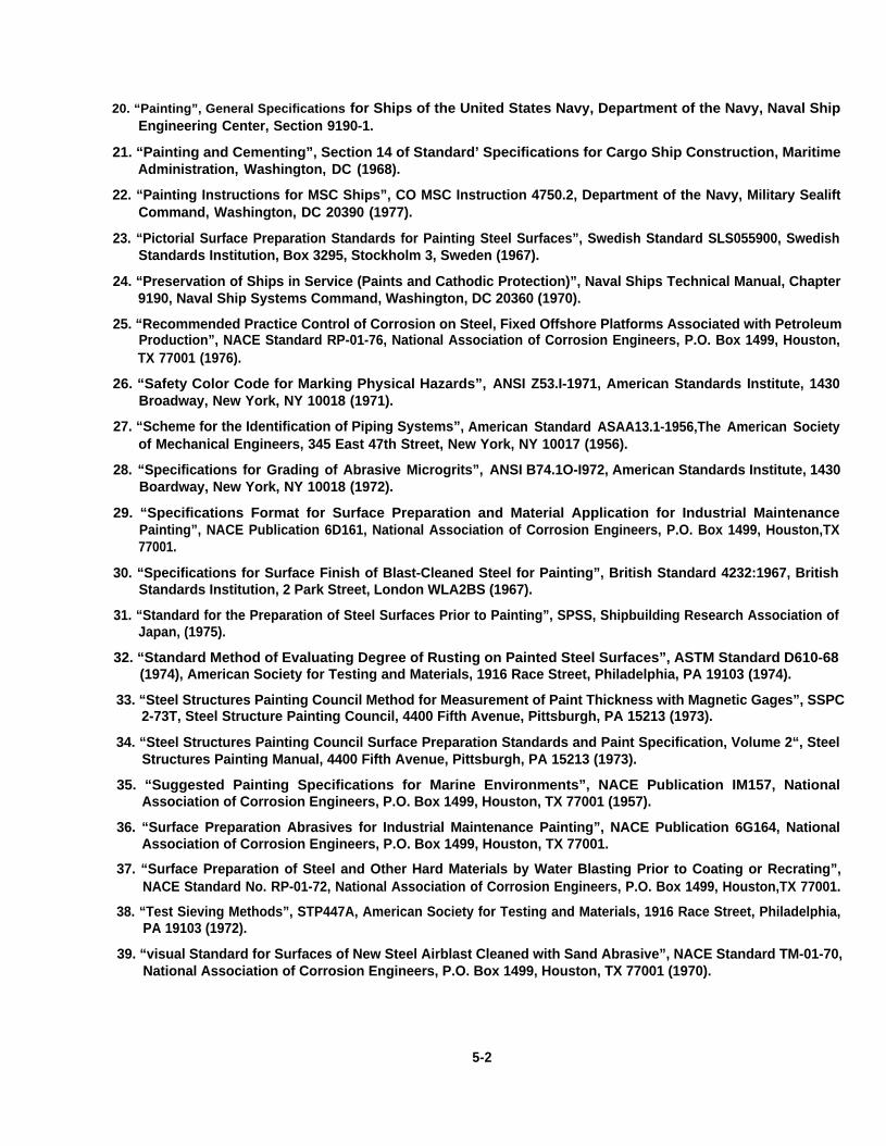
20. “Painting”, General Specifications for Ships of the United States Navy, Department of the Navy, Naval ShipEngineering Center, Section 9190-1.
21. “Painting and Cementing”, Section 14 of Standard’ Specifications for Cargo Ship Construction, MaritimeAdministration, Washington, DC (1968).
22. “Painting Instructions for MSC Ships”, CO MSC Instruction 4750.2, Department of the Navy, Military SealiftCommand, Washington, DC 20390 (1977).
23. “Pictorial Surface Preparation Standards for Painting Steel Surfaces”, Swedish Standard SLS055900, SwedishStandards Institution, Box 3295, Stockholm 3, Sweden (1967).
24. “Preservation of Ships in Service (Paints and Cathodic Protection)”, Naval Ships Technical Manual, Chapter9190, Naval Ship Systems Command, Washington, DC 20360 (1970).
25. “Recommended Practice Control of Corrosion on Steel, Fixed Offshore Platforms Associated with PetroleumProduction”, NACE Standard RP-01-76, National Association of Corrosion Engineers, P.O. Box 1499, Houston,TX 77001 (1976).
26. “Safety Color Code for Marking Physical Hazards”, ANSI Z53.I-1971, American Standards Institute, 1430Broadway, New York, NY 10018 (1971).
27. “Scheme for the Identification of Piping Systems”, American Standard ASAA13.1-1956,The American Societyof Mechanical Engineers, 345 East 47th Street, New York, NY 10017 (1956).
28. “Specifications for Grading of Abrasive Microgrits”, ANSI B74.1O-I972, American Standards Institute, 1430Boardway, New York, NY 10018 (1972).
29. “Specifications Format for Surface Preparation and Material Application for Industrial MaintenancePainting”, NACE Publication 6D161, National Association of Corrosion Engineers, P.O. Box 1499, Houston,TX77001.
30. “Specifications for Surface Finish of Blast-Cleaned Steel for Painting”, British Standard 4232:1967, BritishStandards Institution, 2 Park Street, London WLA2BS (1967).
31. “Standard for the Preparation of Steel Surfaces Prior to Painting”, SPSS, Shipbuilding Research Association ofJapan, (1975).
32. “Standard Method of Evaluating Degree of Rusting on Painted Steel Surfaces”, ASTM Standard D610-68(1974), American Society for Testing and Materials, 1916 Race Street, Philadelphia, PA 19103 (1974).
33. “Steel Structures Painting Council Method for Measurement of Paint Thickness with Magnetic Gages”, SSPC2-73T, Steel Structure Painting Council, 4400 Fifth Avenue, Pittsburgh, PA 15213 (1973).
34. “Steel Structures Painting Council Surface Preparation Standards and Paint Specification, Volume 2“, SteelStructures Painting Manual, 4400 Fifth Avenue, Pittsburgh, PA 15213 (1973).
35. “Suggested Painting Specifications for Marine Environments”, NACE Publication IM157, NationalAssociation of Corrosion Engineers, P.O. Box 1499, Houston, TX 77001 (1957).
36. “Surface Preparation Abrasives for Industrial Maintenance Painting”, NACE Publication 6G164, NationalAssociation of Corrosion Engineers, P.O. Box 1499, Houston, TX 77001.
37. “Surface Preparation of Steel and Other Hard Materials by Water Blasting Prior to Coating or Recrating”,NACE Standard No. RP-01-72, National Association of Corrosion Engineers, P.O. Box 1499, Houston,TX 77001.
38. “Test Sieving Methods”, STP447A, American Society for Testing and Materials, 1916 Race Street, Philadelphia,PA 19103 (1972).
39. “visual Standard for Surfaces of New Steel Airblast Cleaned with Sand Abrasive”, NACE Standard TM-01-70,National Association of Corrosion Engineers, P.O. Box 1499, Houston, TX 77001 (1970).
5-2
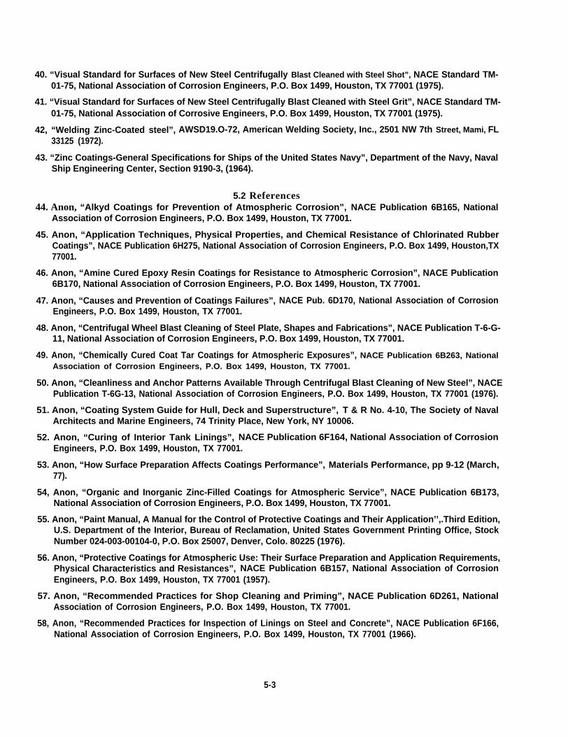
40. “Visual Standard for Surfaces of New Steel Centrifugally Blast Cleaned with Steel Shot”, NACE Standard TM-01-75, National Association of Corrosion Engineers, P.O. Box 1499, Houston, TX 77001 (1975).
41. “Visual Standard for Surfaces of New Steel Centrifugally Blast Cleaned with Steel Grit”, NACE Standard TM-01-75, National Association of Corrosive Engineers, P.O. Box 1499, Houston, TX 77001 (1975).
42, “Welding Zinc-Coated steel”, AWSD19.O-72, American Welding Society, Inc., 2501 NW 7th Street, Mami, FL33125 (1972).
43. “Zinc Coatings-General Specifications for Ships of the United States Navy”, Department of the Navy, NavalShip Engineering Center, Section 9190-3, (1964).
5.2 References44. Anon, “Alkyd Coatings for Prevention of Atmospheric Corrosion”, NACE Publication 6B165, National
Association of Corrosion Engineers, P.O. Box 1499, Houston, TX 77001.
45. Anon, “Application Techniques, Physical Properties, and Chemical Resistance of Chlorinated RubberCoatings”, NACE Publication 6H275, National Association of Corrosion Engineers, P.O. Box 1499, Houston,TX77001.
46. Anon, “Amine Cured Epoxy Resin Coatings for Resistance to Atmospheric Corrosion”, NACE Publication6B170, National Association of Corrosion Engineers, P.O. Box 1499, Houston, TX 77001.
47. Anon, “Causes and Prevention of Coatings Failures”, NACE Pub. 6D170, National Association of CorrosionEngineers, P.O. Box 1499, Houston, TX 77001.
48. Anon, “Centrifugal Wheel Blast Cleaning of Steel Plate, Shapes and Fabrications”, NACE Publication T-6-G-11, National Association of Corrosion Engineers, P.O. Box 1499, Houston, TX 77001.
49. Anon, “Chemically Cured Coat Tar Coatings for Atmospheric Exposures”, NACE Publication 6B263, NationalAssociation of Corrosion Engineers, P.O. Box 1499, Houston, TX 77001.
50. Anon, “Cleanliness and Anchor Patterns Available Through Centrifugal Blast Cleaning of New Steel”, NACEPublication T-6G-13, National Association of Corrosion Engineers, P.O. Box 1499, Houston, TX 77001 (1976).
51. Anon, “Coating System Guide for Hull, Deck and Superstructure”, T & R No. 4-10, The Society of NavalArchitects and Marine Engineers, 74 Trinity Place, New York, NY 10006.
52. Anon, “Curing of Interior Tank Linings”, NACE Publication 6F164, National Association of CorrosionEngineers, P.O. Box 1499, Houston, TX 77001.
53. Anon, “How Surface Preparation Affects Coatings Performance”, Materials Performance, pp 9-12 (March,77).
54, Anon, “Organic and Inorganic Zinc-Filled Coatings for Atmospheric Service”, NACE Publication 6B173,National Association of Corrosion Engineers, P.O. Box 1499, Houston, TX 77001.
55. Anon, “Paint Manual, A Manual for the Control of Protective Coatings and Their Application’’,.Third Edition,U.S. Department of the Interior, Bureau of Reclamation, United States Government Printing Office, StockNumber 024-003-00104-0, P.O. Box 25007, Denver, Colo. 80225 (1976).
56. Anon, “Protective Coatings for Atmospheric Use: Their Surface Preparation and Application Requirements,Physical Characteristics and Resistances”, NACE Publication 6B157, National Association of CorrosionEngineers, P.O. Box 1499, Houston, TX 77001 (1957).
57. Anon, “Recommended Practices for Shop Cleaning and Priming”, NACE Publication 6D261, NationalAssociation of Corrosion Engineers, P.O. Box 1499, Houston, TX 77001.
58, Anon, “Recommended Practices for Inspection of Linings on Steel and Concrete”, NACE Publication 6F166,National Association of Corrosion Engineers, P.O. Box 1499, Houston, TX 77001 (1966).
5-3

59. Anon, “Straight and Midified Phenolic COatings for Atmospheric Service”, NACE publication 6B167, NationalAssociation of Corrosion Engineers, P.O. Box 1499, Houston, TX 77001.
60. Anon, “Top Coating of Zinc Rich Primers for Atmospheric Exposure”, NACE Publication T-6 H-24, NationalAssociation of Corrosion Engineers, P.O. Box 1499, Houston, TX 77001 (1978).
61. Anon, “Urethane Protective Coatings for Atmospheric Exposures”, NACE Publication 6B273, NationalAssociation of Corrosion Engineers, P.O. Box 1499, Houston, TX 77001.
62. Anon, “Vinyl Coatings for Prevention of Atmospheric Corrosion”, NACE Publication 6B163, NationalAssociation of Corrosion Engineers, P.O. Box 1499, Houston, TX 77001.
63. Anon, “Zinc Filled Inorganic Coatings”, NACE Publication 6B161, National Association of CorrosionEngineers, P.O. Box 1499, Houston, TX 77001.
64. Banov, Abel, “Paints and Coatings Handbook for Contractors, Architects, Builders and Engineers”, StructuresPublishing Company, Box 423, Farmington, Mich. 48024 (1973).
65. Bigos, joseph, “Anchor Pattern Profile and Its Effect on Paint Performance”, Corrosion, pp 428t - 432t, (Aug.1959).
66. Bruno, Joseph Dr., “Surface Profile for Anti-Corrosion Coatings”, Proceeding of Eighteenth Annual MarineCoatings Conference, March 22-24 (1978).
67. Burns, R.M. and Bradley, W.W., “Protective Coatings for Metals”, ACS Monograph No. 163, ReinholdPublishing Corp., New York (1967).
68. Chapman, B.N. and Anderson, J. C., “Science and Technology of Surface Coating”, Academic Press Inc., 111Fifth Avenue, New York, NY 10003 (1974).
69. Deere, Derek H., “Corrosion in Marine Environment, International Sourcebook 1: Ship Painting andCorrosion”, Hemisphere Publishing Corporation, 1024 Vermont Avenue, NW, Washington, DC 20005 (1974).
70. Dickerson, W. P., “Paint Guarantees or Quality Assurance”, Proceeding of 2nd Inter. Ship Paint and Corr.Conf., March 11-12 (1976).
71. Doherty, Chad B., “Surface Produced by Abrasive Blasting of Steel”, Materials Performance, pp. 13-20 (Nov.1977).
72. Gross, William F., “Applications Manual for Paints and Protective Coatings”, McGraw-Hill Book Company,New York (1970).
. 73. Hamilton, W.W., “A Naval Architect’s Thoughts on Specifications for Coatings”, Am. Paint j. Conv. Dailyy, 62(20), pp36-38, (29 Oct. 77).
74. Hitzrot, H.W., “Surface Preparation of Steel - Research to Production”, proceedings of Eighteenth AnnualMarine Coatings Conference, March 22-24 (1978).
75. Keane, John D. and Shoemaker, T. L., “Development of Specifications for Measurement of Paint Thickness onStructural Steel”, Journal of Paint Technology, pp 46-67, (Oct. 1973).
76. Keane, J. D., “Painting of Hand Cleaned Steel, A Progress Report”, Steel Structural Painting Council, 4400 FifthAvenue, Pittsburgh, PA 15213 (1964).
77. Keane, John D. and Donatelli, Paul, “Surface Profile for Anti-Corrosive Painting of Structural Steel”, SteelStructure Painting Council, 4400 Fifth Avenue, Pittsburgh, PA 15213 (1974).
78. La Rue, F. L., “Marine Corrosion”, Wiley and Sons, New York.
79. Leanse, Jay L, “COatings Inspection: A Low Cost, High Return Investment”, Proceeding of SeventeenthAnnual Marine Coatings Conference, March 16-18 (1977).
80. McKelvie, “Monitoring Cleanliness and Profile of Blast Cleaned Steel”, Materials Performance, (Oct. 1974).
5-4

81. McKelvie, A. N., “Steel Cleaning Standards - A Case for Their Reappraisal”, J. Oil Co]. Chem. Assoc., pp 227-237, (June 1977).
82. Montgomery, John M., “Regulatory Activities As They Impact on Marine Coatings”, American Paint andCoating Journal, pp 40-46, (July 1978).
83. Morgenstein, E.A. and Dear, H., “U.S. Navy Coating Specifications”, Proceedings of Seventeenth AnnualMarine Coatings Conference, March 16-18 (1977).
84. Murphy, James A., “Surface Preparation and Finishes for Metals”, McGraw-Hill Book Company, New York(1971).
85. Obrzut, John T., “Shot Blast C[eaning Heads in New Directions”, Iron Age, pp 27-31, (16 Aug. 76).
86. Obrzut, John T., “Some New Thoughts About Cleaning Steel for Painting”, Iron Age, pp 52-53,56’57, (27March 78).
87. Pearson, William W., “Surface Preparation Specifications”, Proceedings of Seventeenth Annual MarineCOatings Conference, March 16-18 (1977).
88. Pludek, V. R., “Design and Corrosion Control”, John Wiley and Sons, New York (1976).
89. Podesta, D., “Effects of the Parameters of Abrasive Grains on Metal Removal Rates in Loose Abrasive Systems”,Finishing Industries, pp 21-24,29 (Feb. 78).
90. Ranney, William M., “Coatings-Recent Developments”, Noyes Data Corporation, noyes Building, Park Ridge,New Jersey 07656 (1976).
91. Roberts, Aaron Gene, “Organic Coatings, Properties, Selection, and Use”, Building Science Series 7, UnitedStates Department of COmmerce, National Bureau of Standards, Washington, DC 20234 (1968).
92. Rogers, Howard T., “Marine Corrosion”, George Newnes Ltm., Torver House, Southampton St., London,WC2, UK (1968).
93. Schneberger, Gerald T., “Understanding Paint”, Third Printing, Hitchcock Publishing Co., 1700 West ThirdAvenue, flint, Michigan 48502 (1975).
94. Shrier, L. L., “Corrosion” Volume 2 “Corrosion Control”, Newnes-Butterworths, 19 Cummings Park, Woburn,Mass. 01801 (1977).
95. Spring, S., “industrial Cleaning”, Prism Press, Melborne, Australia (1974),
96. Starkenberg, Charles J., “The Shipbuilder On Corrosion Control”, Proceedings of Seventeenth AnnualMarine Coatings Conference, March 16-18 (1977).
97. Teller, Michael, “Topcoating Inorganic Zincs”, Proceedings of Seventeenth Annual Marine CoatingsConference, March 16-18, (1977).
98. Woods, Kevin and Spring, Samuel, “Selection of Pretreatment System”, Metal Finishing, pp 17-22, (June 1978).
ANNEX ARecapitulation of
Shipbuilder Responses

APPENDIX 1GUIDE TO PROTECTIVE COATINGS (PAINT) SELECTION
1.0 SCOPEThe recommendations contained in this appendix are believed to be technically sound and current, but are
not to be considered as requirements to this standard.
2.o In selecting the desired protective coating system, a number of points should be remembered. These pointsare discussed below:A. Severity of intended service condition. Listed below, in order of descending severity, are the various general
areas of the ship. ,1. Underwater Bottom 8. Cargo Holds2. Boottop 9. Machinery Spaces3. Tanks 9.1 Bilge
3.1 Ballast 9.2 Hot Surfaces3.2 Product (depends on product) 9.3 Bulkhead and Overhead
4. Freeboard 9.4 Decks5. Exterior Decks 9.5 Machinery6. Superstructure 10. Living and Working Spaces7. Exterior Machinery 11. Dry Voids
B. Desired design life of the system is an important point. Asa general rule, high performance coatings with highinitial cost are more cost effective over a time period. However, never select a highly sophisticated protectivesystem without knowledge of all the risks, and only if a less sophisticated system will not fulfill therequirements.
C. Consideration should be given to primer coats that can protect the steel for extended construction cycles(normally 6 to 9 months) and can withstand abrasion due to handling. Do not use primers which continue toharden with age, such as epoxy ester. Also, primers should be capable of being welded thru, more or less,without liberation of toxic fumes, have fast dry (10 to 20 min.) and be compatible with various top coats.
D. Ease of maintenance and ease of application. Both of these points must be taken into consideration whenselecting a paint system. If the new construction yard and/or repair yard cannot successfully apply thespecified material, the entire painting operation is an exercise in futility. For this reason, it is extremelyimportant to review paint vendor supplied Product/Procedure Data Sheets for environmental considerations,special equipment or special skills required prior to making the final material selection.
E. Another point, water base inorganic zinc should be selected for application in geographical areas of lowhumidity and alkyl (solvent based) types in areas of high humidity.
F. Thermoplastic coatings and coatings which harden by solvent evaporation (vinyl, chlorinated rubber, etc.) aregenerally more easily repaired than thermoset materials (polyurethane, epoxies, esters, etc.).
G. Health and Safety (see Section 8.0 of Basic Specification).H. Be careful in selecting topcoats for inorganic zinc types of material. Do not select topcoats of material from
drying oil paints nor modified drying oil paints.L Inorganic zinc paints are generally corrosion resistant from pH 6.0 to 9.5.j. Exterior marine coatings are usually exposed to high-intensity ultraviolet light from the sun. Consideration ‘
should be given to materials that resist color change and/or chalking under such considerations.K. It is becoming common for protective coating suppliers to recommend the combining of different generic
types of material within the same system to gain the benefits of both; for example, an epoxy middle coat canbe overcoated with various finish coats such as urethanes, vinyl, vinyl acrylics, chlorinated rubber, epoxiesand others. Extreme care must be used in this approach. Only materials specified should be used.
A-i

3.o The references listed below may be helpful in making specific protective coatings selections.
ReferenceMarAd Paint Performance Study
Code of Practice for Protective Coating ofIron & Steel Structures Against Corrosion,BS5493:1977
Design & Corrosion Contro[V.R. Pludek
Paints & Coatings Handbook by Abel Banov
Volumes 1 & 2, Steel Structures Painting Council
Corrosion, Volume 2, Corrosion Control,Edited by L.L. Shreir
Corrosion in Marine Environment,International Sourcebook 1: Ship Painting &Corrosion; Edited by Derek H. Deere
Coating Systems Guide for Hull,Deck and Superstructure, T & R No. 4-10
Chapter 16 of Marine Corrosionby F.L. LaRue
Understanding Paint and Painting Processesby Gerald L. Schneberger
Ship Painting Manual by A.M. Berendsen
SourceU.S. Department of CommerceMaritime AdministrationWashington, DC 20230AlTN: M-920
British Standards Institution, Publications Manager101 Pentonville Road, London N19ND,United Kingdom
Published in USA by Halsted Press, a division ofJohn Wiley and Son, Inc., New York, New York
Structures Publishing Co.Box 423, Farmington, Mich. 48024
Steel Structures Painting Council4400 Fifth Avenue, Pittsburgh, PA 15213
Newnes-Butterworth, Butterworth, Inc.19 Cummings Park, Woburn, Ma 01801
Hemisphere publishing Corporation,1024 Vermont Avenue, NWWashington, DC 20005
The Society of Naval Architects and MarineEngineers, 74 Trinity PlaceNew York, New York 10006
Wiley and SonsNew York, New York
Hitchcock Publishing Co.,Hitchcock Building, Wheaton, ILL. 60187
Barbara A. Chin, RSV (North American), Inc.20 Exchange PlaceNew York, NY 10005
A-ii
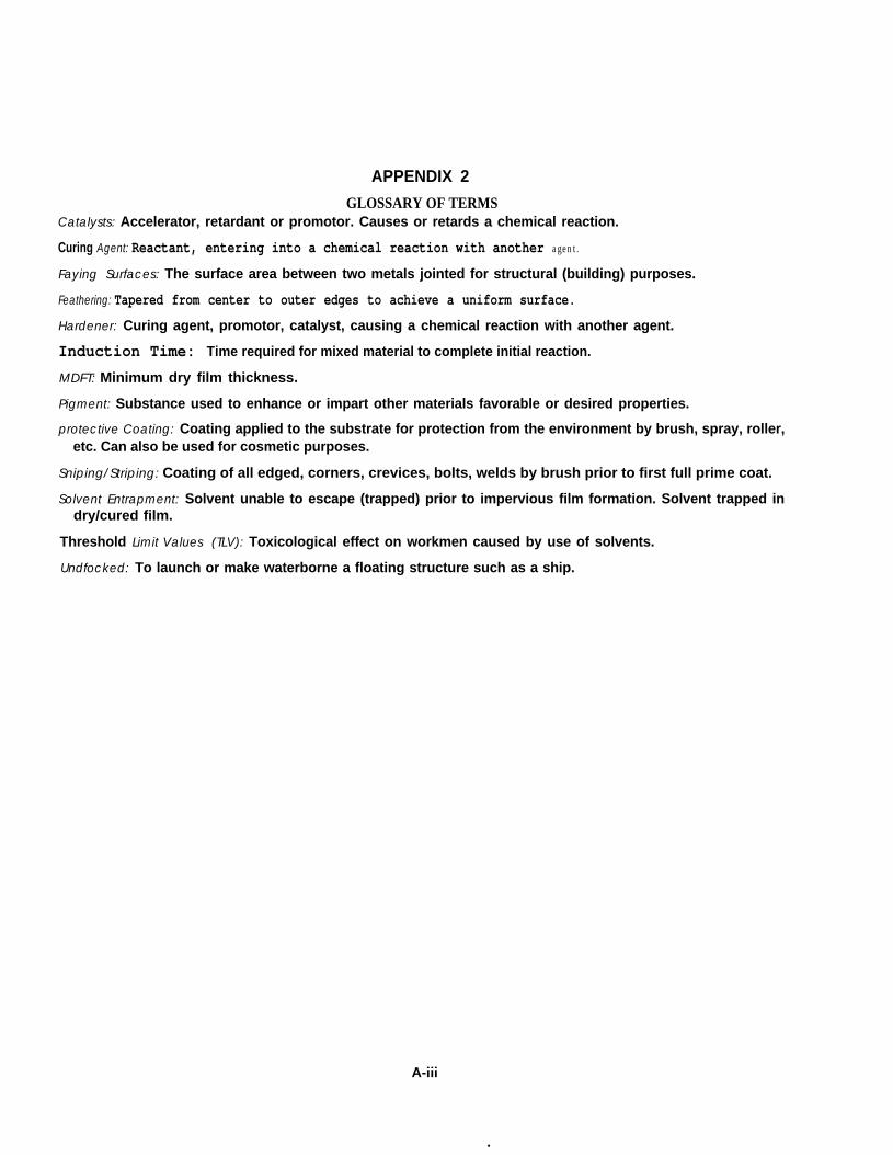
APPENDIX 2
GLOSSARY OF TERMSCatalysts: Accelerator, retardant or promotor. Causes or retards a chemical reaction.
Curing Agent: Reactant, entering into a chemical reaction with another agent.
Faying Surfaces: The surface area between two metals jointed for structural (building) purposes.
Feathering: Tapered from center to outer edges to achieve a uniform surface.
Hardener: Curing agent, promotor, catalyst, causing a chemical reaction with another agent.
Induction Time: Time required for mixed material to complete initial reaction.
MDFT: Minimum dry film thickness.
Pigment: Substance used to enhance or impart other materials favorable or desired properties.
protective Coating: Coating applied to the substrate for protection from the environment by brush, spray, roller,etc. Can also be used for cosmetic purposes.
Sniping/Striping: Coating of all edged, corners, crevices, bolts, welds by brush prior to first full prime coat.
Solvent Entrapment: Solvent unable to escape (trapped) prior to impervious film formation. Solvent trapped indry/cured film.
Threshold Limit Values (TLV): Toxicological effect on workmen caused by use of solvents.
Undfocked: To launch or make waterborne a floating structure such as a ship.
A-iii
.
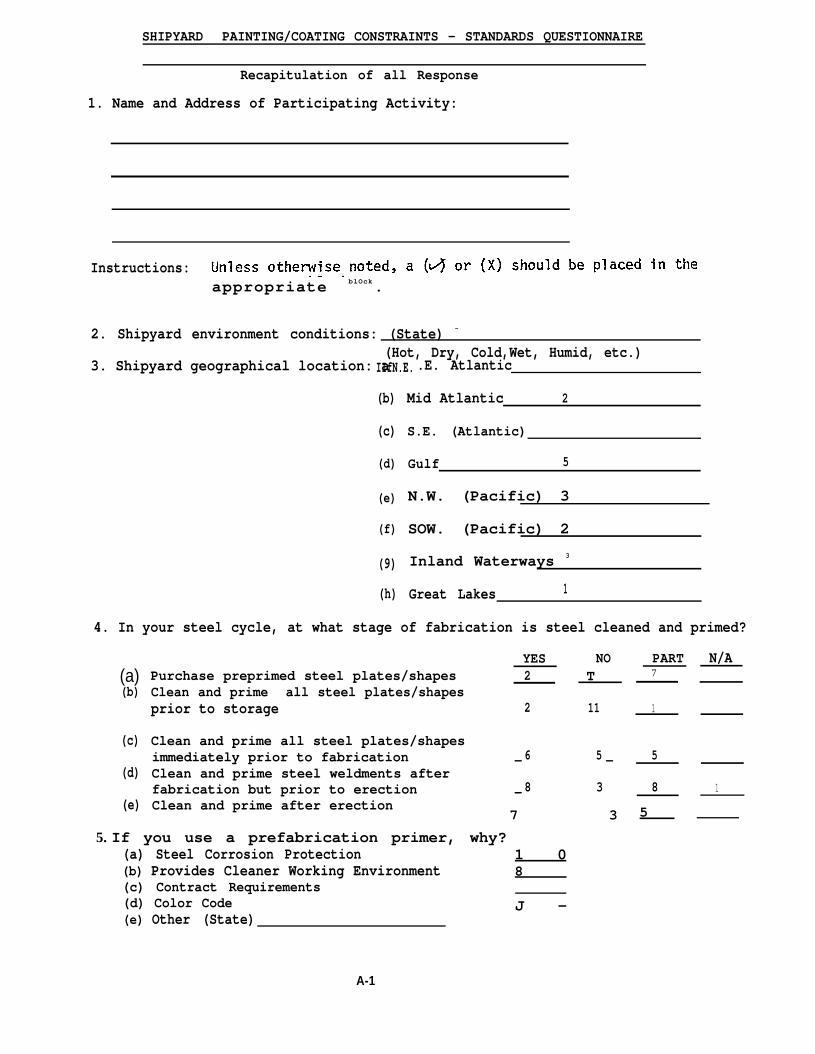
SHIPYARD PAINTING/COATING CONSTRAINTS - STANDARDS QUESTIONNAIRE
Recapitulation of all Response
1. Name and Address of Participating Activity:
Instructions:appropriate blOck.
2. Shipyard environment conditions: (State) -
IIfN.E.(Hot, Dry, Cold,Wet, Humid, etc.)
3. Shipyard geographical location: a .E. Atlantic
(b)
(c)
(d)
(e)
(f)
(9)
(h)
4. In your steel cycle, at what stage of fabrication is steel cleaned and primed?
Mid Atlantic 2
S.E. (Atlantic)
Gulf 5
N.W. (Pacific) 3
SOW. (Pacific) 2
Inland Waterways 3
Great Lakes 1
(a)(b)
(c)
(d)
(e)
YES NOPurchase preprimed steel plates/shapes 2 TClean and prime all steel plates/shapesprior to storage 2 11
Clean and prime all steel plates/shapesimmediately prior to fabrication 6 5Clean and prime steel weldments after
— —
fabrication but prior to erection 8 3Clean and prime after erection
—
7 3
5. If you use a prefabrication primer, why?(a) Steel Corrosion Protection 1 0(b) Provides Cleaner Working Environment 8(c) Contract Requirements(d) Color Code(e) Other (State)
J -
A-1
PART7
1
5
8
5
N/A
1

6.
7.
8.
9.
Do you remove prefabrication primer afterfabrication and rep,rime prior to erection?
Do you remove prefabrication primer afterfabrication and erection but prior to finalpaint/coating application?
Initial surface preparation: YES
(a)
(b)
(c)
(d)
(e)
(f)
Automatic Abrasive Blasting 13
Manual Abrasive Blasting 8
Automatic Power Tool Cleaning 1
Manual Power Tool Cleaning 5
Chemical Cleaning
YES
1YES
NO
6
4
9
6
9— .
NO PART N/A
9 4 3“NO PART N/A
ABRASIVE TYPE/SIZE (Stat~iS-50, S-390, S-460G-40, S-330, S-280
G-230, J-50
Other (State) Broom Cleaning to Remove Construction Debris Only
Touch Up Surface Preparation Prior to Final Paint/Coatings Application:
(a )
(b)
(c)
(d)
(e)
(f)
Automatic Abrasive Blasting
Manual Abrasive Blasting
Manual Power Tool Cleaning
Hand Tool Cleaning
Chemical Cleaning
Other (State).
10. Do you “weld thru” Primers
(a) Manual Stick-.
(b) SAW
(c) SMAW
(d) GMAW - Solid Wire
(e) GMAW - Cored Wire
(f) Other (State) FAB
1
17
15
11
2
YES
11
4
5
3
4
2
11
2
2
2
8
NO
6
13
13 “
13
14
0
Mineral Grit, Sand,Coal Slag, 20-40 Mesh.Ottawa Silica, GlassShot
YES, BUT AT REDUCED RATE
2
7
1
3
1
0
A-2
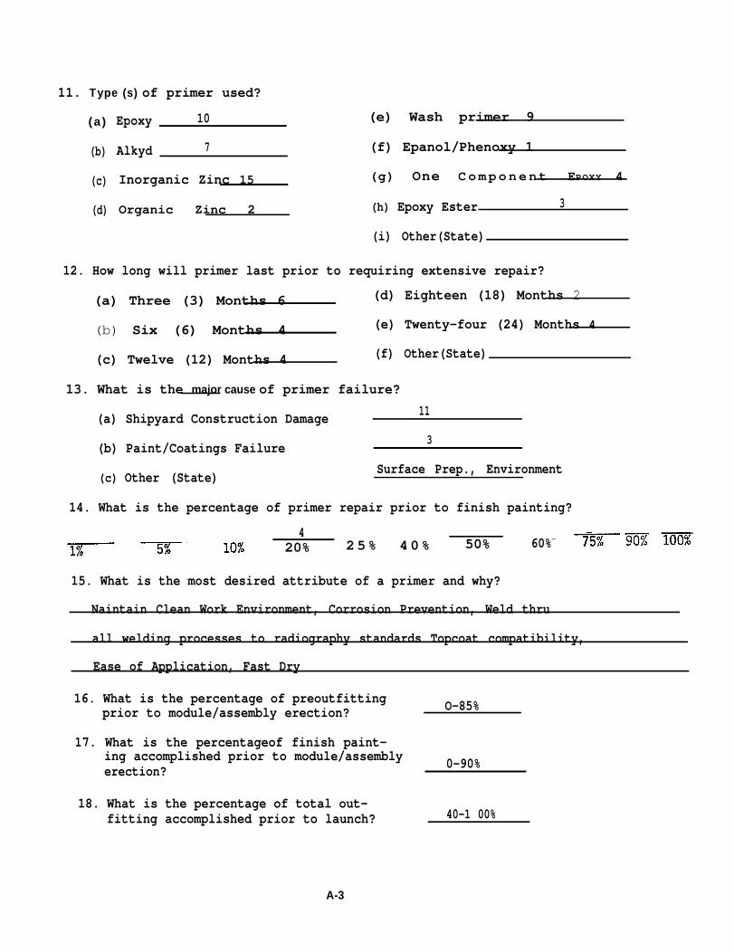
11. Type (s) of primer used?
(a )
(b)
(c)
(d)
Epoxy 10 (e) Wash primer 9
Alkyd 7 (f) Epanol/Phenoxy 1
Inorganic Zinc 15 (g) One Component EPOXY 4
Organic Zinc 2 (h) Epoxy Ester 3
(i) Other(State)
12. How long will primer last prior to requiring extensive repair?
(a) Three (3) Months 6 (d) Eighteen (18) Months 2
(b) Six (6) Months 4 (e) Twenty-four (24) Months 4
(c) Twelve (12) Months 4 (f) Other(State)
13. What is the major cause of primer failure?
(a) Shipyard Construction Damage 11
(b) Paint/Coatings Failure 3
(c) Other (State) Surface Prep., Environment
14. What is the percentage of primer repair prior to finish painting?
420% 25% 40% 50% —60%
15. What is the most desired attribute of a primer and why?
Naintain Clean Work Environment, Corrosion Prevention, Weld thru
all welding processes to radiography standards Topcoat compatibility,
Ease of Application, Fast Dry
16. What is the percentage of preoutfittingprior to module/assembly erection? O-85%
17. What is the percentageof finish paint-ing accomplished prior to module/assemblyerection? 0-90%
18. What is the percentage of total out-fitting accomplished prior to launch? 40-1 00%
A-3
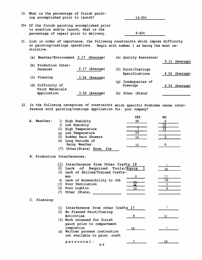
19.
20•
21.
22.
What is the percentage of finish paint-ing accomplished prior to launch? 15-95%
Of the finish painting accomplished priorto erection and/or launch, what is thepercentage of repair prior to delivery. 5-40%
List in order of importance, the following constraints which impose difficultyon painting/coatings operations. Begin with number 1 as being the most re-strictive.
(a) Weather/Environment 2.17 (Averaqe)
(b) Production Inter-ferences 2.17 (Average)
(c) Planning 3.56 (Averaqe)
(d) Difficulty ofPaint MaterialsApplication 3.59 (Average)
In the following categories of constraints
(e) Quality Assurance/5.11 (Average)
(f) Paint/CoatingsSpecifications 4.24 (Average)
(g) Inadequacies ofDrawings 6.53 (Averaqe)
(h) Other (State)
which specific Problems cause inter-ference with painting/coatings application for. your company?
YES15
NOA. Weather:
1)(2)
(3)(4)(5)(6)
High HumidityLow HumidityHigh TemperatureLow TemperatureSudden Rain ShowersLong Periods ofRainy Weather
125
16
10(7) Other(State) Snow, Ice
B. Production Interferences:
(1)(2)(3)
Interference from Other Crafts 18Lack of Required Tools/Equip 1Lack of Skilled/Trained Crafts-
118
man 2
[4)5)
(6)(7)
Lack of Accessibility to JobPoor VentilationPoor LightinOther (State)
1210
79
C. Planning:
(1)(2)
Interference from other Crafts 17No Planned Paint/Coating
7
ActivitiesWork released for finish
8 11(3)
paint prior to compartmentcompletion 16Written process instructionnot available to paint..craft
-2
(4)
p e r s o n n e l : 3A-4
16

C. Planning. (con’t)
5. Other (State)
. D. Paint/Coatings Materials:
(1)(2)(3)(4)(5)(6)(7)(8)
(9)
Short Pot LifeSlow Cure/DryUnpleasant OdorLow FlashpointMinimum Recoat Time Too LongMaximum Recoat Time Too ShortLack of Application InstructionsApplication Method Too Compli-cated for average craftsmanSurface Prep cannot be accom-plished
( 10) Other (State)
E. QualityAssurance/Control
(1)
(2)
(3)
(4)
Written Instructions withinspection attributes are notavailable to inspectorsInspectors are not schooltrainedInspection attributes are purelysubjective
YES121277
1257
2--
NO
17
4 15
5
6
5Other (State) personality o f Inspectors-
F. Paints/Coatings Specifications:
(1) Specifications are overlyrestrictive
(2) Speci fi cations contains5
production sequencingrequirements which cannotbe followed. 3
(3) Other (State) SDecifications notcompatible with shipyard methods
G. Paint/Coatings Finishing Schedules:
(1) Incomplete Schedules(2) Schedules/Drawings difficult
to understand
14
13
14
14
16
1517
(3) Other (State)
H. List in order of priority five.(5)major shipyard paint/coatings problems/constraints. 9. Material Application Requirements
Obtaining Required Cleanliness Standardsobtaining Film Thickness with Specified Number of Coats 10. AccessibilityElimination of Paint Pinholes 11. Atmospheric ConditionsInspectors not trained 12. Blistering in TanksSpecifiations Too Subiective Tralning & Qualif. of PersonnelSafety Problems 14. Equipment Down TimeCraft Interference 15 Unable to qualify WeldProduction/Scaffolding Damage A-5 1 6 . S t r u c t u r a l I n t e r f e r e n c e s

23. Does the Coatings/Paint Supplier Provide directon the job assistance to craft personnel on aroutine basis?
24. QUALITYASSURANCE/QUALITY CONTROL:
(1) Marine Surveyor Inspectiont(2) Owner Inspec ion
(3) QA/QC Dept. Inspectors.(4) Craft Inspectors(5) Craft Supervision Inspection Only(6) QA/QC Dept. Audit Only(7) Are Inspectors School Trained?(8) Are Written Instruction Sheets Used?(9) Other (State)
25. Paints/Coatings Specifications And Standards:
(1)
(2)
(3)(4)
(5)
Are paints/coatings specificationscomplete?Are paints/coatings specificationsoverly restrictiveAre paints/coatings standards used?Are specifications available directlyto craft personnel?Which of the following Standards are used?(a) Steel Structure Painting CouncilSurface Preparation Standards(b) National Association of CorrosionEngineer (NACE) Visual Standards forBlast Cleaned Steel(c) NBS Certified Coating ThicknessCalibration Standards(d) Steel Structures Painting CouncilPaint Thickness Measurements SSPC-PA2-73T(e) The Society of Naval Architectsand Marine Engineers Abrasive BlastingGuide for Aged or Coated Steel(f) Japanese Standard for the Preparationof Steel Surfaces Prior to Painting(g) Pictorial Surface PreparationStandards for painting steel surfaces(h) ASTM D 2697 - 73,-Volume Nonvol-atile matter in Clear or PigmentedCoatings(i) Other: (State)
YES
10
1419158624
13
10
15
7
9
13
4
NO
9
504
1113171510
6
96
9
4
12
10
6
15
1
9
5
18
10
14
26. Please attach any Paint/Coatings Specifications and/or Process Instructionspresently being utilized in your operations.
THANK YOU FOR YOUR COOPERATION
A-6

ANNEX BRecapitulation of
Marine Coating SupplierResponses
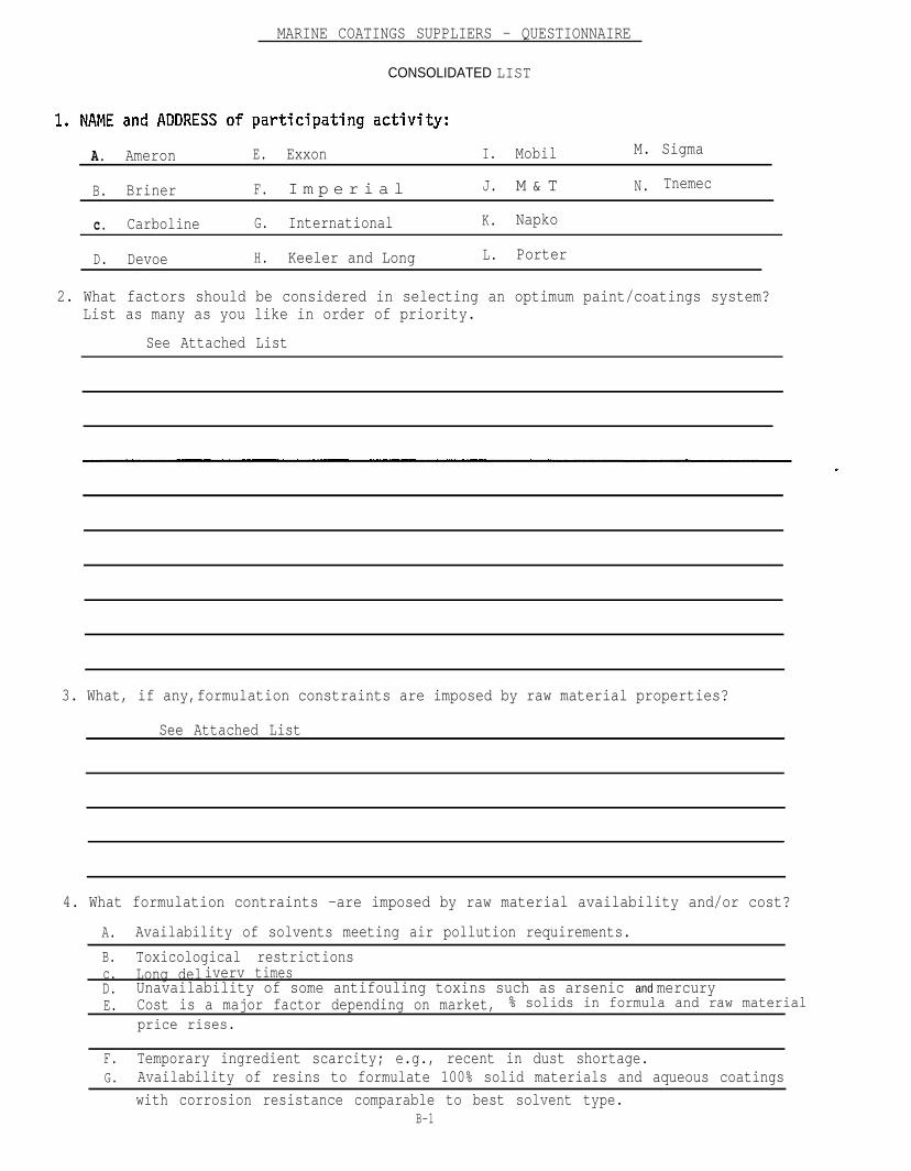
MARINE COATINGS SUPPLIERS - QUESTIONNAIRE
CONSOLIDATED LIST
A. Ameron E. Exxon I. Mobil M. Sigma
B. Briner F. I m p e r i a l J. M & T N. Tnemec
c. Carboline G. International K. Napko
D. Devoe H. Keeler and Long L. Porter
2. What factors should be considered in selecting an optimum paint/coatings system?List as many as you like in order of priority.
See Attached List
3. What, if any,formulation constraints are imposed by raw material properties?
See Attached List
4. What formulation contraints -are imposed by raw material availability and/or cost?
A. Availability of solvents meeting air pollution requirements.
B. Toxicological restrictionsc. Long deliverv timesD. Unavailability of some antifouling toxins such as arsenic and mercuryE. Cost is a major factor depending on market, % solids in formula and raw material
price rises.
F. Temporary ingredient scarcity; e.g., recent in dust shortage.G. Availability of resins to formulate 100% solid materials and aqueous coatings
with corrosion resistance comparable to best solvent type.B-1

5.
6.
7.
8.
9.
10.
11.
12.
In your option, what is the optimum number of coats of paint which should be usedin a given paint system?
Three
List the environmental factors which should be considered when applying a paintsystem. Also include a method or standard for measuring a particular factor orcondition.
See Attached List
What method or standard should be used to measure substrate cleanliness prior toPainting/coating? Visual by owners representative, Japanese SPSS - SSPC SurfacePreparation Standards, NACE Visual Standards, SNAME Standards, Swedish PictorialStandards; white handkerchief.
Should a materials qualification testing program be instituted to qualify coatingsystems for the following ships areas? If so, what standard should be used?
a. Underwater Bottom 7 - yes; 2- No; 5 - No comment
b. Freeboard 4 - yes; 4 - No; 6 - No commentc. Tanks, Ballast 6 - yes; 3 - No; 5 - No commentd. Tanks, Potable Water 4 -yes: 3 -No; 7 -No commente. Tanks, Clean Cargo 5 -f. Tanks, Crude
ves: 3 - No: 6 - No comment6 - ves: 3 - N o : 5 - No comment
g. Cargo Holds/Spaces 2 - ves: 5 - No; 7 - No commenth. Engine/Machfnery Spaces 2 - yes; 5 - No; 7 - No commentj. Living Spaces l - yes; 6 - No; 5 - No comment
Should paint inspectors be qualified/certified to a standard? If yes, what standard/method? 14 - yes; o - no; o - No comment - No standard presently available. Somevendors provide service; ASTM, NACE presently working on standards.
Is blast profile an important factor in paint/coating system performance? If yes,what is the optimum, how can it be measured and to what standard?
Yes - Varies with vendor. Depends on dry film thickness; “optimum is 1/3 of DFT”;
no standard presently exists. Keane-Tator Profile comparator; Clemco comparator;
SSPC Microscopic method; Profilometer; pull off thickness gauge; select abrasiveparticle size.
How should dry film measurement be accomplished? SSPC-PA~2-Magnetic pull-off gauge;“Manufacturer” method not taking into account profile, “Tooke” gauge.
How should film thickness measuring devices be calibrated and to what standard?
SSPC using NBS Standards; ASTM E-376-69
13.How should volume solids be measured and verified? What standard should be used?Inorganic zinc - volatile measurement or wet/dry film (GSA Method) Organic Coatings -
ASTM D-2697B-2

14.
15.
16.
17.
18.
What attributes should be measured and verified during application of paints/coatings/
A. Surface Cleanliness F. Film Thickness (Wet & Dry) K. Equipment Set-up
B. Profile G. Dry Times between Coats L. Quality of Air
c. Temperature and Humidity H. Ventilation M. Film Appearance
D. Humidity I. Holidays (Spark Test) N. Time before immersior
E 4 ~ Correct Nixing and Thinning J. Area Coated o. Hardness
Weight per Gallon Q. Viscosity R. Solvent Concentrationshould painters be qualified/certified in accordance with a program similar to t h e welder qualification standards?
12 - Yes; 2 - No; no program available
If You could write a specification exactly the way You wanted to. what would be theformat? Include generic types and a rational
Would your company be interested in attendingsometime in the month of November 1977?The purpose of the seminar will be to discuss
for using each type.
a seminar at Offshore Power Systems
input and goals of the program.
Would your company be interested in participating in a materials test program wheregeneric products from different sources are evaluated on an equal basis?
B-3
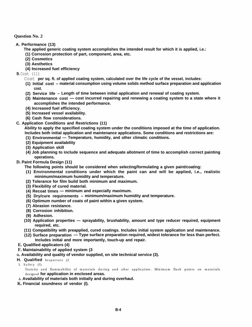
Question No. 2
A. Performance (13)The applied generic coating system accomplishes the intended result for which it is applied, i.e.:(1) Corrosion protection of part, component, area, etc.(2) Cosmetics(3) Aesthetics(4) Increased fuel efficiency
B. Cost (11)Cost per sq. ft. of applied coating system, calculated over the life cycle of the vessel, includes:(1) Initial cost – material consumption using volume solids method surface preparation and application
cost.(2) Service life – Length of time between initial application and renewal of coating system.(3) Maintenance cost — cost incurred repairing and renewing a coating system to a state where it
accomplishes the intended performance.(4) Increased fuel efficiency.(5) Increased vessel availability.(6) Cash flow considerations.
C. Application Conditions and Restrictions (11)Ability to apply the specified coating system under the conditions imposed at the time of application.Includes both initial application and maintenance applications. Some conditions and restrictions are:(1) Environmental — Temperature, humidity, and other climatic conditions.(2) Equipment availability(3) Application skill(4) Job planning to include sequence and adequate allotment of time to accomplish correct painting
operations.D. Paint Formula Design (11)
The following points should be considered when selecting/formulating a given paint/coating:(1) Environmental conditions under which the paint can and will be applied, i.e., realistic
minimum/maximum humidity and temperature.(2) Tolerance for film build both minimum and maximum.(3) Flexibility of cured material.(4) Recoat times — minimum and especially maximum.(5) Dry/cure requirements – minimum/maximum humidity and temperature.(6) Optimum number of coats of paint within a given system.(7) Abrasion resistance.(8) Corrosion inhibition.(9) Adhesion.
(10) Application properties — sprayability, brushability, amount and type reducer required, equipmentrequired, etc.
(11) Compatibility with preapplied, cured coatings. Includes initial system application and maintenance.(12) Surface preparation — Type surface preparation required, widest tolerance for less than perfect.
Includes initial and more importantly, touch-up and repair.E. Qualified applicators (4)F. Maintainability of applied system (3
G. Availability and quality of vendor supplied, on site technical service (3).H. Qualified Inspectors (2L Safety (l).
Toxicity and flammability of materials during and after application. Minimum flash points on materials
designed for application in enclosed areas.J. Availability of materials both initially and during overhaul.
K. Financial soundness of vendor (l).
B-4
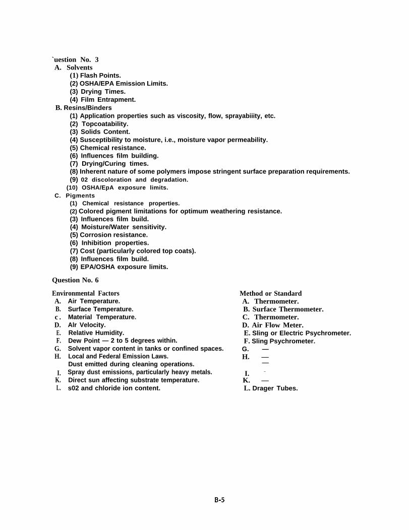
`uestion No. 3A. Solvents
(1) Flash Points.(2) OSHA/EPA Emission Limits.(3) Drying Times.(4) Film Entrapment.
B. Resins/Binders(1) Application properties such as viscosity, flow, sprayabiiity, etc.(2) Topcoatability.(3) Solids Content.(4) Susceptibility to moisture, i.e., moisture vapor permeability.(5) Chemical resistance.(6) Influences film building.(7) Drying/Curing times.(8) Inherent nature of some polymers impose stringent surface preparation requirements.(9) 02 discoloration and degradation.
(10) OSHA/EpA exposure limits.C. Pigments
(1) Chemical resistance properties.(2) Colored pigment limitations for optimum weathering resistance.(3) Influences film build.(4) Moisture/Water sensitivity.(5) Corrosion resistance.(6) Inhibition properties.(7) Cost (particularly colored top coats).(8) Influences film build.(9) EPA/OSHA exposure limits.
Question No. 6
Environmental FactorsA.B.c .D.E.F.
G.H.
I.K.L.
Air Temperature.Surface Temperature.Material Temperature.Alr Velocity.Relative Humidity.Dew Point — 2 to 5 degrees within.Solvent vapor content in tanks or confined spaces.Local and Federal Emission Laws.Dust emitted during cleaning operations.Spray dust emissions, particularly heavy metals.Direct sun affecting substrate temperature.s02 and chloride ion content.
Method or StandardA. Thermometer.B. Surface Thermometer.C. Thermometer.D. Air Flow Meter.E. Sling or Electric Psychrometer.F. Sling Psychrometer.
G. —H. —
—
I. –
K. —L. Drager Tubes.