Embed Size (px)
Citation preview

Report Assignment BENP 2183 Electronic Instrumentations
1
REPORT ASSIGNMENT
1.0 TITLE
Design of basic shunt DC multirange ammeter using Permanent Magnet
Moving Coil (PMMC) of AI fsd µ100= for range of mAmA 1500,1000 −−
and mA300 .
2.0 OBJECTIVES
i. To design a basic shunt DC multirange ammeter using PMMC.
ii. To understand the properties of a basic shunt DC multirange ammeter.
iii. To calculate the current through a circuit measured by basic shunt DC
multirange ammeter using PMMC.
iv. To measure the actual value internal resistance of PMMC.
3.0 EQUIPMENTS/ MATERIALS
NO. EQUIPMENT UNIT/S
1 Resistor 2.2Ω 3
2 PMMC (micro-ammter) 1
3 4 ways switch 1
4.0 THEORY
Meter
A meter is any device built to accurately detect and display an electrical
quantity in a form readable by a human being. Usually this "readable form" is visual:
motion of a pointer on a scale, a series of lights arranged to form a "bar graph," or
some sort of display composed of numerical figures. In the analysis and testing of
circuits, there are meters designed to accurately measure the basic quantities of
voltage, current, and resistance. The display mechanism of a meter is often referred to
as a movement, borrowing from its mechanical nature to move a pointer along a scale
so that a measured value may be read.
The design of most mechanical movements is based on the principle of
electromagnetism: that electric current through a conductor produces a magnetic field
perpendicular to the axis of electron flow. The greater the electric current, the stronger

Report Assignment BENP 2183 Electronic Instrumentations
2
the magnetic field produced. If the magnetic field formed by the conductor is allowed
to interact with another magnetic field, a physical force will be generated between the
two sources of fields. If one of these sources is free to move with respect to the other,
it will do so as current is conducted through the wire, the motion which usually
against the resistance of a spring being proportional to strength of current.
However, practical electromagnetic meter movements can be made now where a
pivoting wire coil is suspended in a strong magnetic field, shielded from the majority
of outside influences. Such an instrument design is generally known as a permanent-
magnet, moving coil, or PMMC movement:
Figure 1: Construction of Permanent Magnet Moving Coil (PMMC)
In the picture above, the meter movement "needle" is shown pointing
somewhere around 35 percent of full-scale, zero being full to the left of the arc and
full-scale being completely to the right of the arc. An increase in measured current
will drive the needle to point further to the right and a decrease will cause the needle
to drop back down toward its resting point on the left. The arc on the meter display is
labeled with numbers to indicate the value of the quantity being measured, whatever
that quantity is.

Report Assignment BENP 2183 Electronic Instrumentations
3
Ammeter
Figure 2: A Typical 0-1mA Ammeter
Figure 3: D’Arsonval used in DC
Ammeter circuit
A meter designed to measure electrical current is popularly called an "ammeter"
because the unit of measurement is "amps." The earliest design is the D'Arsonval
galvanometer or moving coil ammeter. It uses magnetic deflection, where current
passing through a coil causes the coil to move in a magnetic field. The voltage drop
across the coil is kept to a minimum to minimize resistance across the ammeter in any
circuit into which it is inserted.
Besides that, moving iron ammeters use a piece or pieces of iron which move
when acted upon by the electromagnetic force of a fixed coil of wire. This type of
meter responds to both direct and alternating currents as opposed to the moving coil
ammeter, which works on direct current only
To measure larger currents, a resistor called a shunt is placed in parallel with the
meter. Most of the current flows through the shunt, and only a small fraction flow
through the meter. This allows the meter to measure large currents.
Multi-Range Ammeter
In practical terms, ammeters with a single range are not very useful. However
there are some exceptions such as Marine meters-voltage, fuel, Power station meters
(voltage, frequency) and automotive meters (ammeter, tachometer).All of which have
one useful range.
To make an ammeter to measure several ranges at once, one approach is to have
a separate shunt resistor for each range and we can calculate each resistor value of the
shunt.

Report Assignment BENP 2183 Electronic Instrumentations
4
Figure 4: Several Range Meter Connections
By referring to Figure 4, the position of the switch, one of R1 to R4 would be
connected as a shunt across the meter. However, a problem may have with thus
arrangement. At the point when the switch is moved from position 1 to position 2, the
PMMC movement will be forced to pass a current that may be more than full scale
deflection current, fsdI . This will most likely destroy the meter, or at best blow a fuse.
Hence, to solve of this problem another ways of connection can be used. Those are a
make-before-break switch and a Universal or Ayrton Shunt. The make-before-switch
establishes contact with the next contact position before losing contact with the
existing connection. In this manner, the shunt resistors are never removed from the
circuit and the PMMC movement is always protected.
Figure 5: The Make-Before-Switch Connection

Report Assignment BENP 2183 Electronic Instrumentations
5
Figure 6: The Universal or Ayrton shunt of Multi-Range Ammeter
As refer to Figure 5, the Universal or Ayrton shunt connection. The shunt
resistors, R1, R2 and R3, are all in series and collectively in parallel to the meter
movement. Thus,
321 RRRRsh ++=
If the input is connect to position 1, it can be say that
mmm
mmshsh
msh
RIRRRII
RIRI
VV
=++−
=
=
)321)((
Where, Ish = shunt current for this position.
If the input is connect to position 2,
)1()32)(( RRIRRII mmm +=+−
If the input is connect to position 3,
)21()3)(( RRRIRII mmm ++=−
Hence, by using substitution of equations the value of shunt resistors, R1, R2
and R3 can be calculated. Besides, this method is used for this project.
5.0 PROCEDURE
1. A basic shunt DC multirange ammeter was designed using PMMC of
Ifsd=100µA for range of 0-100mA, 0-150mA and 0-300mA.
2. The designed circuit was tested by using Multisim.
3. The internal resistance, Rm for the micro-ammeter was measured by using
DMM.
Report Assignment BENP 2183 Electronic Instrumentations
6
4. The designed circuit was constructed on a breadboard and the circuit was
checked.
5. The observation and the finding were discussed.
6.0 RESULT
Theoretical/ Calculation Result
To design basic shunt DC multirange ammeter using PMMC, the Aryton
Shunt or Universal Shunt was used.
AI fsd µ100=SHI
Figure 1: An Aryton Shunt design circuit
Calculation for circuit in Figure 1 to provide an ammeter with a current range
of mAmA 1500,1000 −− , mA3000 − and AI fsd µ100= .
Firstly, voltage across resistors R1, R2 and R3 parallel with the voltage Rm.
Hence,
MMSHSH
RmSH
RIRI
VV
=
=
But,
fsdSH
fsdSH
III
III
−=∴
+=
For range ,1000 mA−
RmRRRm µµ 100)123)(100100( =++−

Report Assignment BENP 2183 Electronic Instrumentations
7
RmRRRm µ100)123(9.99 =++ -- (1)
For range ,1500 mA−
RmRRm µµ 100)12)(100150( =+−
)3(100)12(9.149 RRmRRm +=+ µ -- (2)
)3(11.667)12( RRmRR +=+ µ -- (3)
For range ,3000 mA−
RmRm µµ 100)1)(100300( =−
)23(100)1(9.299 RRRmRm ++= µ
)23(44.3331 RRRmR ++= µ -- (4)
Substitute equation (3) into equation (1),
[ ][ ]
RmmR
RmRRmmRm
RmRRmRm
RmRRmRm
36.33397.99
100364.6664.669.99
100311.66711.66739.99
100)3(11.66739.99
=
=++
=++
=++
µµµ
µµµ
µµ
RmR µ70.3333 = -- (5)
Substitute equation (3) and equation (4) into equation (2),
[ ]
RmR
RmRmRmR
RRmRRRmR
RRmRRRmRm
µµ
µµµµµµ
µµµµ
µµ
82.333)44.3331(2
)7.333(11.667)7.333(44.33344.333)44.3331(2
)3(11.667244.333344.33344.3332
)3(100)23(44.33329.149
=+
=+++
+=+++
+=+++
RmR µ71.3332 = -- (6)
Substitute equation (5) and equation (6) into equation (4),
Rm
nRmnRmRm
RmRmRm
RRRmR
µ
µ
µµµ
µ
66.333
27.11127.11144.333
)71.33370.333(44.333
)23(44.3331
=
++=
++=
++=
Hence, the value of R3, R2 and R1
RmR
RmR
RmR
µ
µ
µ
66.3331
71.3332
70.3333
=
=
=∴
From the laboratory result, the Rm for the PMMC micro-ammeter is 6.72kΩΩΩΩ
Therefore, the value of R3, R2 and R1

Report Assignment BENP 2183 Electronic Instrumentations
8
Simulation Result
(i) A basic DC circuit of voltage source and resistor was constructed and
measure by using multimeter in Multisim Software.
Figure 2
Calculation by using mathematical method:
By using Ohm’s Law,
)(12
1
12
provedmA
k
R
VI
IRV
calculated
=
=
=
=
Report Assignment BENP 2183 Electronic Instrumentations
9
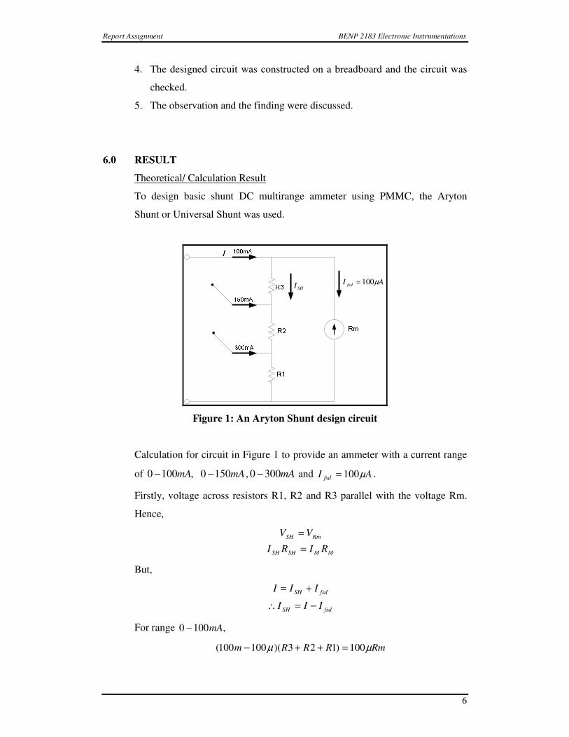
(ii) A designed basic shunt DC Multirange ammeter and connected to a
basic circuit as in Figure 1 was constructed by using Multisim Software.
Figure 3
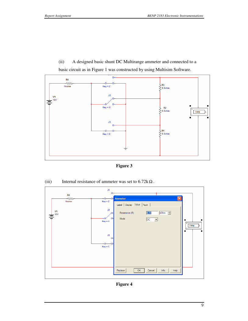
(iii) Internal resistance of ammeter was set to 6.72k Ω .
Figure 4
Report Assignment BENP 2183 Electronic Instrumentations
10
Due to set value of internal resistance, Rm=6.72k Ω hence the resistor’s value
obtained and used in designed basic shunt DC Multirange ammeter was,
Ω=
=
=
Ω=
=
=
Ω=
=
=
242.2
)72.6(66.333
66.3331
242.2
)72.6(71.333
71.3332
242.2
)72.6(70.333
70.3333
k
RmR
k
RmR
k
RmR
µ
µ
µ
µ
µ
µ
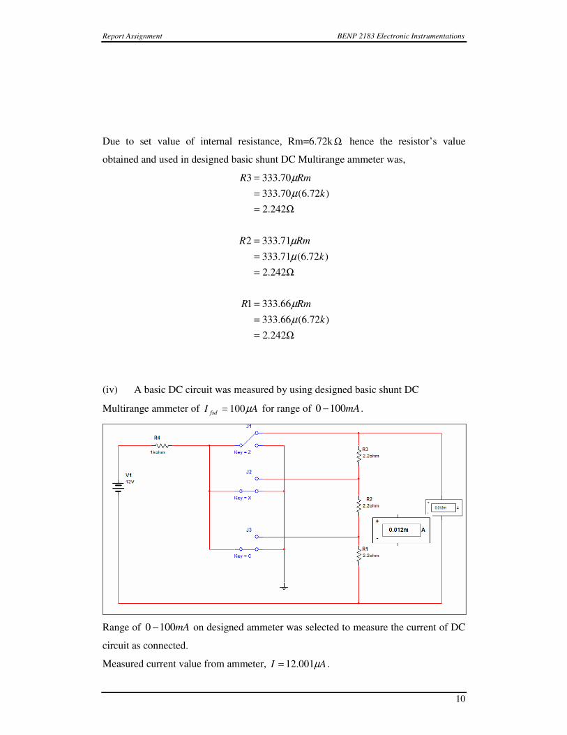
(iv) A basic DC circuit was measured by using designed basic shunt DC
Multirange ammeter of AI fsd µ100= for range of mA1000 − .
Range of mA1000 − on designed ammeter was selected to measure the current of DC
circuit as connected.
Measured current value from ammeter, AI µ001.12= .

Report Assignment BENP 2183 Electronic Instrumentations
11
Hence,
rangeselected
fsd
measured
circuitdc II
II ×=
Given, AI fsd µ100=
mI circuitdc 100100
00.12×=∴
µ
µ
calculatedI
mA
=
= 00.12
(v) A basic DC circuit was measured again by using designed basic shunt DC
Multirange ammeter of AI fsd µ100= for range of mA1500 − .
Range of mA1500 − on designed ammeter was selected to measure the current of DC
circuit as connected.
Measured current value from ammeter, AI µ815.7= .
Hence,
mI circuitdc 150100
815.7×=∴
µ
µ
calculatedImA
mA
≈≈
=
0.12
7225.11

Report Assignment BENP 2183 Electronic Instrumentations
12
(v) A basic DC circuit was measured again by using designed basic shunt DC
Multirange ammeter of AI fsd µ100= for range of mA300 .
Range of mA300 on designed ammeter was selected to measure the current of DC
circuit as connected.
Measured current value from ammeter, AI µ916.3= .
Hence,
mI circuitdc 300100
916.3×=∴
µ
µ
calculatedImA
mA
≈≈
=
0.12
748.11
Laboratory Result
The internal resistance, Rm for the PMMC micro-ammeter is 6.72kΩΩΩΩ
ComponentsComponentsComponentsComponents Measured valueMeasured valueMeasured valueMeasured value
Internal resistance, Rm 6.72kΩ
Resistor 1kΩ 0.989kΩ

Report Assignment BENP 2183 Electronic Instrumentations
13
Resistor 2.2Ω 2.2Ω
SHm
SH
fsdmRR
IRII
+==
µ12.98
6.672.6
)6.6)(100(
=
+=
k
m
The range 0 The range 0 The range 0 The range 0 –––– 100mA 100mA 100mA 100mA
VoltageVoltageVoltageVoltage,Vin,Vin,Vin,Vin
(V)(V)(V)(V)
Measured Measured Measured Measured current,Icurrent,Icurrent,Icurrent,I
((((µµµµAAAA))))
Calculated valueCalculated valueCalculated valueCalculated value,Vo,Vo,Vo,Vo
((((VVVV))))
% error % error % error % error
(%)(%)(%)(%)
10 10 10.08 0.80
11 11 11.09 0.81
12 12 12.10 0.83
13 13 13.10 0.76
14 14 14.11 0.79
15 15 15.12 0.80
16 16 16.13 0.81
17 17 17.13 0.76
18 18 18.14 0.78
19 19 19.15 0.79
20 20 20.16 0.80

Report Assignment BENP 2183 Electronic Instrumentations
14
The range 0 The range 0 The range 0 The range 0 –––– 1 1 1 155550mA0mA0mA0mA
VoltageVoltageVoltageVoltage,Vin ,Vin ,Vin ,Vin
(V)(V)(V)(V)
MeasurMeasurMeasurMeasured current,I ed current,I ed current,I ed current,I
((((µµµµA)A)A)A)
Calculated value,Vo Calculated value,Vo Calculated value,Vo Calculated value,Vo
(V)(V)(V)(V)
% error % error % error % error
(%)(%)(%)(%)
10 7.0 10.58 5.8
11 7.6 11.49 4.45
12 8.0 12.10 0.83
13 9.0 13.61 4.69
14 9.0 13.61 2.78
15 10.0 15.12 0.80
16 11.0 16.63 3.94
17 11.4 17.24 1.41
18 12.0 18.14 0.78
19 13.0 19.65 3.42
20 13.6 20.56 2.80
The range 0 The range 0 The range 0 The range 0 –––– 300300300300mAmAmAmA
VoltageVoltageVoltageVoltage,Vin ,Vin ,Vin ,Vin
(V)(V)(V)(V)
Measured current,I Measured current,I Measured current,I Measured current,I
((((µµµµA)A)A)A)
Calculated value,Vo Calculated value,Vo Calculated value,Vo Calculated value,Vo
(V)(V)(V)(V)
% error % error % error % error
(%)(%)(%)(%)
10 3.6 10.88 8.80
11 4.0 12.09 9.91
12 4.0 12.09 0.75
13 4.4 13.3 2.31

Report Assignment BENP 2183 Electronic Instrumentations
15
14 5.0 15.12 8.0
15 5.2 15.72 4.80
16 5.6 16.93 5.81
17 6.0 18.14 6.71
18 6.0 18.14 0.78
19 6.4 19.35 1.84
20 7.0 21.17 5.85
ForForForFor range 0 range 0 range 0 range 0 –––– 100mA 100mA 100mA 100mA
The calculation of the Vo,
When Vin = 10V
4)( xRrangexI
IVo
fsd
=
V
kxmAx
08.10
989.0)100(12.98
10
=
=µ
µ
When Vin = 11V
11.09V
.989kx(100mA)x012.98
11
=
=µ
µVo
The calculation of the percentage error,
When Vin = 10V,

Report Assignment BENP 2183 Electronic Instrumentations
16
%100||% xYn
XnYnerror
−=
%8.0
%100|10
08.1010|
=
−= x
When Vin = 11V,
%100|11
09.1111|% xerror
−=
%81.0=
ForForForFor range 0 range 0 range 0 range 0 –––– 1 1 1 155550mA0mA0mA0mA
The calculation of the Vo,
When Vin = 10V
4)( xRrangexI
IVo
fsd
=
V
kxmAx
58.10
989.0)150(12.98
7
=
=µ
µ
When Vin = 11V
11.49V
.989kx(150mA)x012.98
6.7
=
=µ
µVo
The calculation of the percentage error,

Report Assignment BENP 2183 Electronic Instrumentations
17
When Vin = 10V,
%100||% xYn
XnYnerror
−=
%8.5
%100|10
58.1010|
=
−= x
When Vin = 11V,
%100|11
49.1111|% xerror
−=
%45.4=
ForForForFor range 0 range 0 range 0 range 0 –––– 303030300mA0mA0mA0mA
The calculation of the Vo,
When Vin = 10V
4)( xRrangexI
IVo
fsd
=
V
kxmAx
88.10
989.0)300(12.98
6.3
=
=µ
µ
When Vin = 11V
12.09V
.989kx(300mA)x012.98
0.4
=
=µ
µVo
The calculation of the percentage error,

Report Assignment BENP 2183 Electronic Instrumentations
18
When Vin = 10V,
%100||% xYn
XnYnerror
−=
%80.8
%100|10
88.1010|
=
−= x
When Vin = 11V,
%100|11
09.1211|% xerror
−=
%91.9=

Report Assignment BENP 2183 Electronic Instrumentations
19
7.0 DISCUSSION/ ANALYSIS
The shunt resistance was very small relative to the internal resistance of the
micro-ammeter. A high voltage that passes through the shunt resistor may cause the
resistor burnt. Therefore, no connection was made from the resistors directly to the
high voltage supply. A resistor which has a high resistance is connected to the shunt
resistor in parallel to avoid the burning of resistors occur.
A Permanent Magnet Moving Coil (PMMC) was used to design an ammeter,.
Before design the ammeter, internal resistance of the PMMC was measured to do the
calculation. The PMMC galvanometer constitutes the basic movement of a dc
ammeter. Since the coil winding of a basic movement is small and light, it can carry
only very small currents. When large currents are to be measured, it is necessary to
bypass a major part of the current through a resistance called a shunt.
The shunt resistance used may consist of a length of constant temperature
resistance wire within the case of instrument. The general requirements of a shunt are
as follows.
a. The temperature coefficient of the shunt and instrument should be low
and nearly identical.
b. The resistance of the shunt should not vary with time.
c. It should carry the current without excessive temperature rise.
d. It should have a low thermal emf.
The current range of the dc ammeter may be further extended by a number of
shunt and it is known as multirange ammeter. A switch can be connected in the circuit
to choose the range desired. The switch used to connect in the circuit must be a low
resistance and high current carrying capacity, since its contacts are in series with low
resistance. To prevent the ammeter broken when in use, the highest current range was
used to measure current first, then decrease the range until good upscale reading is
obtained.
When an ammeter was inserted in a circuit, it always increases the resistance
of the circuit and reduces the current in the circuit. This effect was known as the
ammeter insertion effects. To reduce the insertion effects, the resistance used to
design the ammeter should be as low as possible.
8.0 CONCLUSION

Report Assignment BENP 2183 Electronic Instrumentations
20
After doing this assignment, it is found that the ammeter was design by using
a PMMC. Beside that, to measured a large current, the ammeter can be designed with
a resistor connect parallel with the PMMC or known as shunt. In this assignment, a
basic shunt DC multirange ammeter using PMMC was designed.
Beside that, before design the ammeter, internal resistance of the PMMC was
measured first. When designing the multirange ammeter, some requirements as shown
in the discussion were considered, this is to make sure the ammeter that had designed
have an accurate and a precise reading.
The insertion effects which the ammeter will increases the resistance of the
circuit when connected in the circuit thus decreases the current flow in the circuit also
considered in the design. That is the resistor used to design the ammeter is the resistor
with a low resistance.
9.0 REFERENCES
Book Sources:
i. Kalsi H.S., “Electronic Instrumentation”, Second Edition, Tata
McGraw Hill, 2004.
Internet Sources:
i. Ammeter
http://en.wikipedia.org/wiki/Ammeter
ii. Ammeter Design
http://www.allaboutcircuits.com/vol_1/chpt_8/2.html
iii. Ammeter impact on measured circuit
http://www.allaboutcircuits.com/vol_1/chpt_8/5.html
iv. AMP[Shunt Ammeter Circuit
http://home.cogeco.ca/~rpaisley4/CircuitIndex.html
v. Construction of Voltmeter or Ammeter From a Galvanometer
Report Assignment BENP 2183 Electronic Instrumentations
21
http://www.physics.purdue.edu/~clarkt/Courses/Physics271L/Exp4/ex
p4.html
vi. DC Ammeter
http://tpub.com/content/neets/14188/css/14188_82.htm