Embed Size (px)
Citation preview
All information contained in these materials, including products and product specifications, rep-resents information on the product at the time of publication and is subject to change by Renesas Electronics Corporation without notice. Please review the latest information published by Renesas Electronics Corporation through various means, including the Renesas Electronics Corporation website (http://www.renesas.com).
RL78/G14
Renesas Starter Kit Tutorial Manual (CubeSuite+)
Rev.1.00 Jun 2012
16
RENESAS MCU RL78 Family / G1X Series
Notice 1. All information included in this document is current as of the date this document is issued. Such information, however, is sub-
ject to change without any prior notice. Before purchasing or using any Renesas Electronics products listed herein, please con-firm the latest product information with a Renesas Electronics sales office. Also, please pay regular and careful attention to ad-ditional and different information to be disclosed by Renesas Electronics such as that disclosed through our website.
2. Renesas Electronics does not assume any liability for infringement of patents, copyrights, or other intellectual property rights of third parties by or arising from the use of Renesas Electronics products or technical information described in this document. No license, express, implied or otherwise, is granted hereby under any patents, copyrights or other intellectual property rights of Renesas Electronics or others.
3. You should not alter, modify, copy, or otherwise misappropriate any Renesas Electronics product, whether in whole or in part. 4. Descriptions of circuits, software and other related information in this document are provided only to illustrate the operation of
semiconductor products and application examples. You are fully responsible for the incorporation of these circuits, software, and information in the design of your equipment. Renesas Electronics assumes no responsibility for any losses incurred by you or third parties arising from the use of these circuits, software, or information.
5. When exporting the products or technology described in this document, you should comply with the applicable export control laws and regulations and follow the procedures required by such laws and regulations. You should not use Renesas Electron-ics products or the technology described in this document for any purpose relating to military applications or use by the mili-tary, including but not limited to the development of weapons of mass destruction. Renesas Electronics products and technol-ogy may not be used for or incorporated into any products or systems whose manufacture, use, or sale is prohibited under any applicable domestic or foreign laws or regulations.
6. Renesas Electronics has used reasonable care in preparing the information included in this document, but Renesas Electronics does not warrant that such information is error free. Renesas Electronics assumes no liability whatsoever for any damages in-curred by you resulting from errors in or omissions from the information included herein.
7. Renesas Electronics products are classified according to the following three quality grades: “Standard”, “High Quality”, and “Specific”. The recommended applications for each Renesas Electronics product depends on the product’s quality grade, as indicated below. You must check the quality grade of each Renesas Electronics product before using it in a particular applica-tion. You may not use any Renesas Electronics product for any application categorized as “Specific” without the prior written consent of Renesas Electronics. Further, you may not use any Renesas Electronics product for any application for which it is not intended without the prior written consent of Renesas Electronics. Renesas Electronics shall not be in any way liable for any damages or losses incurred by you or third parties arising from the use of any Renesas Electronics product for an applica-tion categorized as “Specific” or for which the product is not intended where you have failed to obtain the prior written con-sent of Renesas Electronics. The quality grade of each Renesas Electronics product is “Standard” unless otherwise expressly specified in a Renesas Electronics data sheets or data books, etc.
“Standard”: Computers; office equipment; communications equipment; test and measurement equipment; audio and visual
equipment; home electronic appliances; machine tools; personal electronic equipment; and industrial robots. “High Quality”: Transportation equipment (automobiles, trains, ships, etc.); traffic control systems; anti-disaster systems; anti-
crime systems; safety equipment; and medical equipment not specifically designed for life support. “Specific”: Aircraft; aerospace equipment; submersible repeaters; nuclear reactor control systems; medical equipment or
systems for life support (e.g. artificial life support devices or systems), surgical implantations, or healthcare intervention (e.g. excision, etc.), and any other applications or purposes that pose a direct threat to human life.
8. You should use the Renesas Electronics products described in this document within the range specified by Renesas Electronics, especially with respect to the maximum rating, operating supply voltage range, movement power voltage range, heat radiation characteristics, installation and other product characteristics. Renesas Electronics shall have no liability for malfunctions or damages arising out of the use of Renesas Electronics products beyond such specified ranges.
9. Although Renesas Electronics endeavors to improve the quality and reliability of its products, semiconductor products have spe-cific characteristics such as the occurrence of failure at a certain rate and malfunctions under certain use conditions. Further, Renesas Electronics products are not subject to radiation resistance design. Please be sure to implement safety measures to guard them against the possibility of physical injury, and injury or damage caused by fire in the event of the failure of a Renesas Electronics product, such as safety design for hardware and software including but not limited to redundancy, fire control and malfunction prevention, appropriate treatment for aging degradation or any other appropriate measures. Because the evaluation of microcomputer software alone is very difficult, please evaluate the safety of the final products or system manufactured by you.
10. Please contact a Renesas Electronics sales office for details as to environmental matters such as the environmental compatibil-ity of each Renesas Electronics product. Please use Renesas Electronics products in compliance with all applicable laws and regulations that regulate the inclusion or use of controlled substances, including without limitation, the EU RoHS Directive. Renesas Electronics assumes no liability for damages or losses occurring as a result of your noncompliance with applicable laws and regulations.
11. This document may not be reproduced or duplicated, in any form, in whole or in part, without prior written consent of Renesas Electronics.
12. Please contact a Renesas Electronics sales office if you have any questions regarding the information contained in this document or Renesas Electronics products, or if you have any other inquiries.
(Note 1) “Renesas Electronics” as used in this document means Renesas Electronics Corporation and also includes its majority-
owned subsidiaries. (Note 2) “Renesas Electronics product(s)” means any product developed or manufactured by or for Renesas Electronics.
Disclaimer By using this Renesas Starter Kit (RSK), the user accepts the following terms:
The RSK is not guaranteed to be error free, and the entire risk as to the results and performance of the RSK is as-sumed by the User. The RSK is provided by Renesas on an “as is” basis without warranty of any kind whether ex-press or implied, including but not limited to the implied warranties of satisfactory quality, fitness for a particular pur-pose, title and non-infringement of intellectual property rights with regard to the RSK. Renesas expressly disclaims all such warranties. Renesas or its affiliates shall in no event be liable for any loss of profit, loss of data, loss of contract, loss of business, damage to reputation or goodwill, any economic loss, any reprogramming or recall costs (whether the foregoing losses are direct or indirect) nor shall Renesas or its affiliates be liable for any other direct or indirect special, incidental or consequential damages arising out of or in relation to the use of this RSK, even if Renesas or its affiliates have been advised of the possibility of such damages.
Precautions The following precautions should be observed when operating any RSK product:
This Renesas Starter Kit is only intended for use in a laboratory environment under ambient temperature and humidity conditions. A safe separation distance should be used between this and any sensitive equipment. Its use outside the laboratory, classroom, study area or similar such area invalidates conformity with the protection requirements of the Electromagnetic Compatibility Directive and could lead to prosecution. The product generates, uses, and can radiate radio frequency energy and may cause harmful interference to radio communications. However, there is no guarantee that interference will not occur in a particular installation. If this equipment causes harmful interference to radio or television reception, which can be determined by turning the equip-ment off or on, you are encouraged to try to correct the interference by one or more of the following measures;
· ensure attached cables do not lie across the equipment
· reorient the receiving antenna
· increase the distance between the equipment and the receiver
· connect the equipment into an outlet on a circuit different from that which the receiver is connected
· power down the equipment when not is use
· consult the dealer or an experienced radio/TV technician for help NOTE: It is recommended that wherever possible shielded interface cables are used.
The product is potentially susceptible to certain EMC phenomena. To mitigate against them it is recommended that the following measures be undertaken;
· The user is advised that mobile phones should not be used within 10m of the product when in use.
· The user is advised to take ESD precautions when handling the equipment. The Renesas Starter Kit does not represent an ideal reference design for an end product and does not fulfil the regula-tory standards for an end product.
How to Use This Manual
1. Purpose and Target Readers This manual is designed to provide the user with an understanding of the RSK hardware functionality, and electrical characteristics. It is intended for users designing sample code on the RSK platform, using the many different incor-porated peripheral devices. The manual comprises of an overview of the capabilities of the RSK product, but does not intend to be a guide to embedded programming or hardware design. Particular attention should be paid to the precautionary notes when using the manual. These notes occur within the body of the text, at the end of each section, and in the Usage Notes section.
The revision history summarizes the locations of revisions and additions. It does not list all revisions. Refer to the text of the manual for details.
The following documents apply to the RL78G14 Group. Make sure to refer to the latest versions of these docu-ments. The newest versions of the documents listed may be obtained from the Renesas Electronics Web site.
2. List of Abbreviations and Acronyms
Abbreviation Full Form ADC Analogue to Digital Converter API Application Programming Interface CD Compact Disk CPU Central Processing Unit E1 E1 Emulator LCD Liquid Crystal Display LED Light Emitting Diode ROM Read-Only Memory RSK Renesas Starter Kit RTC Real Time Clock USB Universal Serial Bus
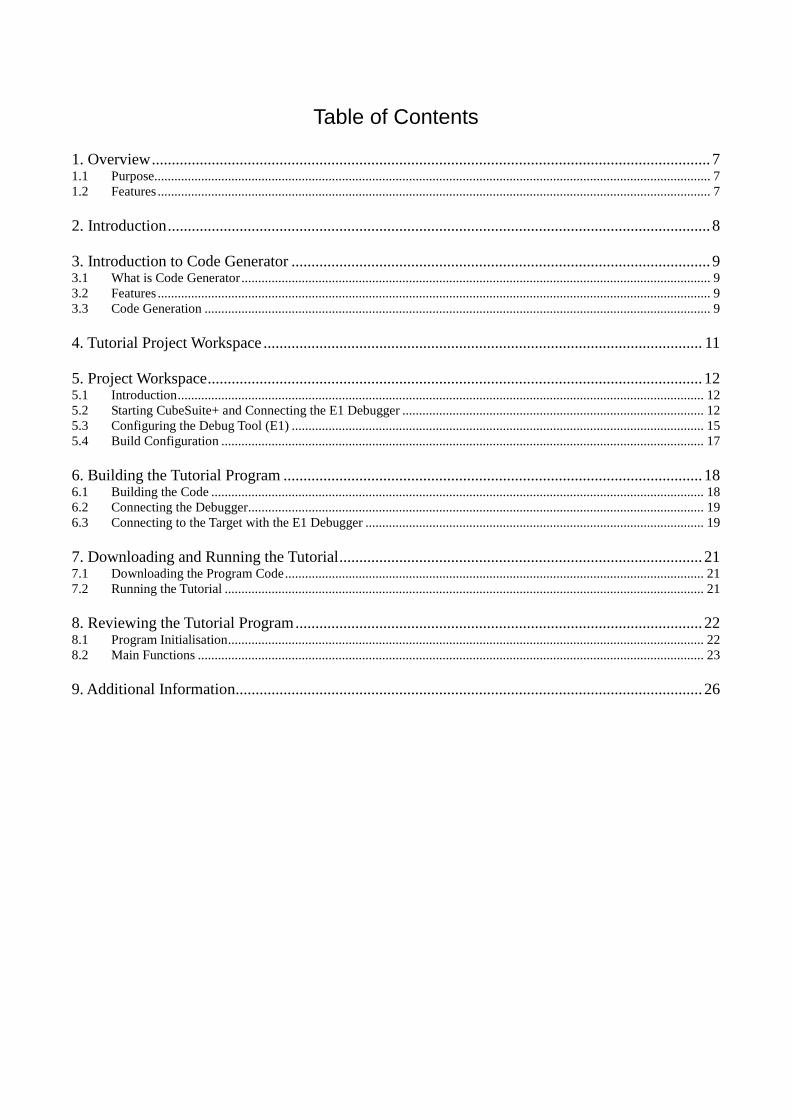
Table of Contents
1. Overview ............................................................................................................................................ 7 1.1 Purpose...................................................................................................................................................................... 7 1.2 Features ..................................................................................................................................................................... 7
2. Introduction ........................................................................................................................................ 8
3. Introduction to Code Generator ......................................................................................................... 9 3.1 What is Code Generator ............................................................................................................................................ 9 3.2 Features ..................................................................................................................................................................... 9 3.3 Code Generation ....................................................................................................................................................... 9
4. Tutorial Project Workspace .............................................................................................................. 11
5. Project Workspace ............................................................................................................................ 12 5.1 Introduction ............................................................................................................................................................. 12 5.2 Starting CubeSuite+ and Connecting the E1 Debugger .......................................................................................... 12 5.3 Configuring the Debug Tool (E1) ........................................................................................................................... 15 5.4 Build Configuration ................................................................................................................................................ 17
6. Building the Tutorial Program ......................................................................................................... 18 6.1 Building the Code ................................................................................................................................................... 18 6.2 Connecting the Debugger ........................................................................................................................................ 19 6.3 Connecting to the Target with the E1 Debugger ..................................................................................................... 19
7. Downloading and Running the Tutorial ........................................................................................... 21 7.1 Downloading the Program Code ............................................................................................................................. 21 7.2 Running the Tutorial ............................................................................................................................................... 21
8. Reviewing the Tutorial Program ...................................................................................................... 22 8.1 Program Initialisation .............................................................................................................................................. 22 8.2 Main Functions ....................................................................................................................................................... 23
9. Additional Information ..................................................................................................................... 26
RSKRL78G14 R20UT0786EG0100 Rev.1.00 RENESAS STARTER KIT Jun 21, 2012
R20UT0786EG0100 Rev. 1.00 Page 7 of 30 Jun 21, 2012
1. Overview
1.1 Purpose This RSK is an evaluation tool for Renesas microcontrollers. This manual describes how to get the RSK tutorial started, and basic debugging operations.
1.2 Features This RSK provides an evaluation of the following features: · Renesas microcontroller programming · User code debugging · User circuitry such as switches, LEDs and a potentiometer · Sample application · Sample peripheral device initialisation code The RSK board contains all the circuitry required for microcontroller operation.
RSKRL78G14 2. Introduction
R20UT0786EG0100 Rev. 1.00 Page 8 of 30 Jun 21, 2012
2. Introduction
This manual is designed to answer, in tutorial form, the most common questions asked about using a Renesas Start-er Kit (RSK). The tutorials help explain the following: · How do I compile, link, download and run a simple program on the RSK? · How do I build an embedded application? · How do I use Renesas’ tools? The project generator will create a tutorial project with two selectable build configurations. · ‘DefaultBuild’ is a project with debug support and optimisation level set to two. · ‘DebugBuild’ is a project built with the debugger support included. Optimisation is set to zero. · ‘ReleaseBuild’ is a project with optimised compile options, producing code suitable for release in a product. Files referred to in this manual are installed using the project generator as you work through the tutorials. The tuto-rial examples in this manual assume that installation procedures described in the RSK Quick Start Guide have been completed. Please refer to the quick start guide for details of preparing the configuration.
These tutorials are designed to show you how to use the RSK and are not intended as a comprehensive introduction to the CubeSuite+’s debugger, compiler toolchains or the E1 emulator. Please refer to the relevant user manuals for more in-depth information.
RSKRL78G14 3. Introduction to Code Generator
R20UT0786EG0100 Rev. 1.00 Page 9 of 30 Jun 21, 2012
3. Introduction to Code Generator
3.1 What is Code Generator Code Generator is a design tool which enables you to output the source code (device driver programs, C source files and header files) necessary to control the peripheral hardware functions provided by the microcontroller de-vice (clock generator, port functions, etc.) by configuring various information using the GUI. This tool is integrated into CubeSuite+.
3.2 Features The Code Generator has the following features:
- Reporting function You can output configured information using the Code Generator as files in various formats for use as design documents.
- Renaming function The user can change default names assigned to the files output by Code Generator and the API functions contained in the source code.
- Code generating function Code Generator can output not only device driver programs in accordance with the information configured using the GUI, but also a build environment such as sample programs containing main functions and link directive files.
- Project/workspace file generating function
3.3 Code Generation The following steps serve as a short presentation of how to generate source code using the Code Generator design tool for a new project/subproject. It assumes that a project already exists and is opened. For more details on how to use Code Generator, refer to the document “CubeSuite+ V1.02.00 Integrated Develop-ment Environment User’s Manual: RL78 Design”. · Double-click the Code Generator (Design Tool)
from the Project Tree pane to reveal the list of pe-ripherals.
RSKRL78G14 3. Introduction to Code Generator
R20UT0786EG0100 Rev. 1.00 Page 10 of 30 Jun 21, 2012
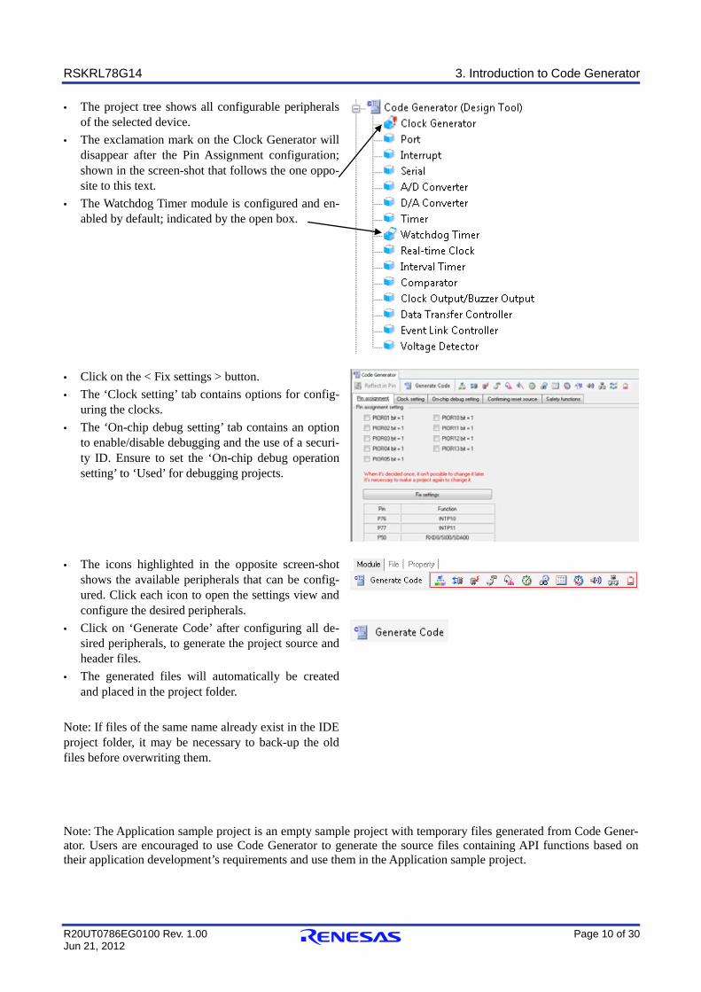
· The project tree shows all configurable peripherals of the selected device.
· The exclamation mark on the Clock Generator will disappear after the Pin Assignment configuration; shown in the screen-shot that follows the one oppo-site to this text.
· The Watchdog Timer module is configured and en-abled by default; indicated by the open box.
· Click on the < Fix settings > button. · The ‘Clock setting’ tab contains options for config-
uring the clocks. · The ‘On-chip debug setting’ tab contains an option
to enable/disable debugging and the use of a securi-ty ID. Ensure to set the ‘On-chip debug operation setting’ to ‘Used’ for debugging projects.
· The icons highlighted in the opposite screen-shot shows the available peripherals that can be config-ured. Click each icon to open the settings view and configure the desired peripherals.
· Click on ‘Generate Code’ after configuring all de-sired peripherals, to generate the project source and header files.
· The generated files will automatically be created and placed in the project folder.
Note: If files of the same name already exist in the IDE project folder, it may be necessary to back-up the old files before overwriting them.
Note: The Application sample project is an empty sample project with temporary files generated from Code Gener-ator. Users are encouraged to use Code Generator to generate the source files containing API functions based on their application development’s requirements and use them in the Application sample project.
RSKRL78G14 4. Tutorial Project Workspace
R20UT0786EG0100 Rev. 1.00 Page 11 of 30 Jun 21, 2012
4.Tutorial Project Workspace
The project includes all of the files required to get started. The tutorial code is designed to show how code can be written, debugged and then downloaded. Contents of common C files are controlled with defines set up in the build configuration options and #ifdef state-ments within the source files. Maintaining only one set of project files means that projects are more controllable.
RSKRL78G14 5. Project Workspace
R20UT0786EG0100 Rev. 1.00 Page 12 of 30 Jun 21, 2012
5. Project Workspace
5.1 Introduction CubeSuite+ is an integrated development tool that allows the user to write, compile, program and debug a software project on the RX, 78K, RL and V850 family of Renesas Microcontrollers. CubeSuite+ will have been installed during the installation of the software support for the Renesas Starter Kit product. This manual will describe the stages required to create and debug the supplied tutorial code.
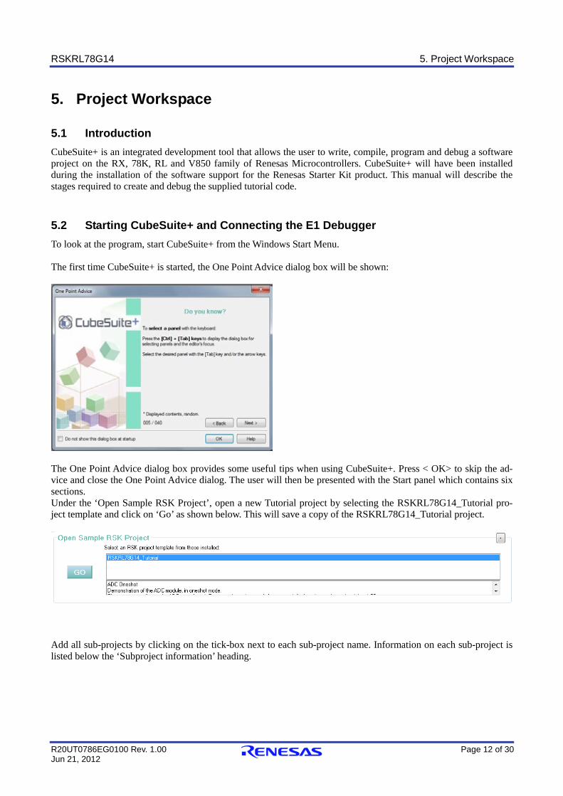
5.2 Starting CubeSuite+ and Connecting the E1 Debugger To look at the program, start CubeSuite+ from the Windows Start Menu. The first time CubeSuite+ is started, the One Point Advice dialog box will be shown:
The One Point Advice dialog box provides some useful tips when using CubeSuite+. Press < OK> to skip the ad-vice and close the One Point Advice dialog. The user will then be presented with the Start panel which contains six sections. Under the ‘Open Sample RSK Project’, open a new Tutorial project by selecting the RSKRL78G14_Tutorial pro-ject template and click on ‘Go’ as shown below. This will save a copy of the RSKRL78G14_Tutorial project.
Add all sub-projects by clicking on the tick-box next to each sub-project name. Information on each sub-project is listed below the ‘Subproject information’ heading.
RSKRL78G14 5. Project Workspace
R20UT0786EG0100 Rev. 1.00 Page 13 of 30 Jun 21, 2012
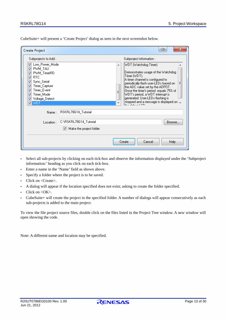
CubeSuite+ will present a ‘Create Project’ dialog as seen in the next screenshot below.
· Select all sub-projects by clicking on each tick-box and observe the information displayed under the ‘Subproject
information:’ heading as you click on each tick-box. · Enter a name in the ‘Name’ field as shown above. · Specify a folder where the project is to be saved. · Click on <Create>. · A dialog will appear if the location specified does not exist; asking to create the folder specified. · Click on <OK>. · CubeSuite+ will create the project in the specified folder. A number of dialogs will appear consecutively as each
sub-projects is added to the main project. To view the file project source files, double click on the files listed in the Project Tree window. A new window will open showing the code. Note: A different name and location may be specified.
RSKRL78G14 5. Project Workspace
R20UT0786EG0100 Rev. 1.00 Page 14 of 30 Jun 21, 2012
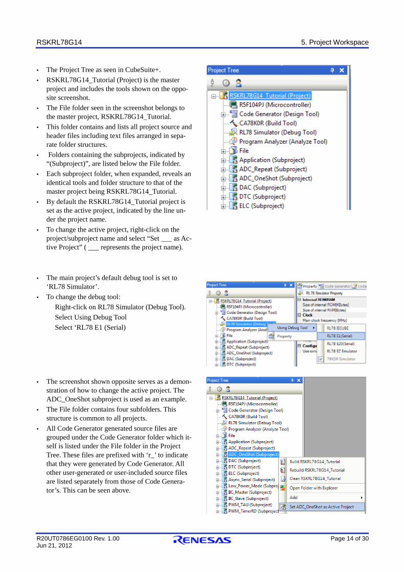
· The Project Tree as seen in CubeSuite+. · RSKRL78G14_Tutorial (Project) is the master
project and includes the tools shown on the oppo-site screenshot.
· The File folder seen in the screenshot belongs to the master project, RSKRL78G14_Tutorial.
· This folder contains and lists all project source and header files including text files arranged in sepa-rate folder structures.
· Folders containing the subprojects, indicated by “(Subproject)”, are listed below the File folder.
· Each subproject folder, when expanded, reveals an identical tools and folder structure to that of the master project being RSKRL78G14_Tutorial.
· By default the RSKRL78G14_Tutorial project is set as the active project, indicated by the line un-der the project name.
· To change the active project, right-click on the project/subproject name and select “Set ___ as Ac-tive Project” ( ___ represents the project name).
· The main project’s default debug tool is set to
‘RL78 Simulator’. · To change the debug tool:
Right-click on RL78 Simulator (Debug Tool). Select Using Debug Tool Select ‘RL78 E1 (Serial)
· The screenshot shown opposite serves as a demon-
stration of how to change the active project. The ADC_OneShot subproject is used as an example.
· The File folder contains four subfolders. This structure is common to all projects.
· All Code Generator generated source files are grouped under the Code Generator folder which it-self is listed under the File folder in the Project Tree. These files are prefixed with ‘r_’ to indicate that they were generated by Code Generator. All other user-generated or user-included source files are listed separately from those of Code Genera-tor’s. This can be seen above.
RSKRL78G14 5. Project Workspace
R20UT0786EG0100 Rev. 1.00 Page 15 of 30 Jun 21, 2012
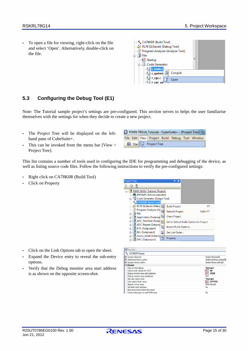
· To open a file for viewing, right-click on the file and select ‘Open’. Alternatively, double-click on the file.
5.3 Configuring the Debug Tool (E1) Note: The Tutorial sample project’s settings are pre-configured. This section serves to helps the user familiarise themselves with the settings for when they decide to create a new project.
· The Project Tree will be displayed on the left-hand pane of CubeSuite+.
· This can be invoked from the menu bar [View > Project Tree].
This list contains a number of tools used in configuring the IDE for programming and debugging of the device, as well as listing source code files. Follow the following instructions to verify the pre-configured settings: · Right click on CA78K0R (Build Tool) · Click on Property
· Click on the Link Options tab to open the sheet. · Expand the Device entry to reveal the sub-entry
options. · Verify that the Debug monitor area start address
is as shown on the opposite screen-shot.
RSKRL78G14 5. Project Workspace
R20UT0786EG0100 Rev. 1.00 Page 16 of 30 Jun 21, 2012
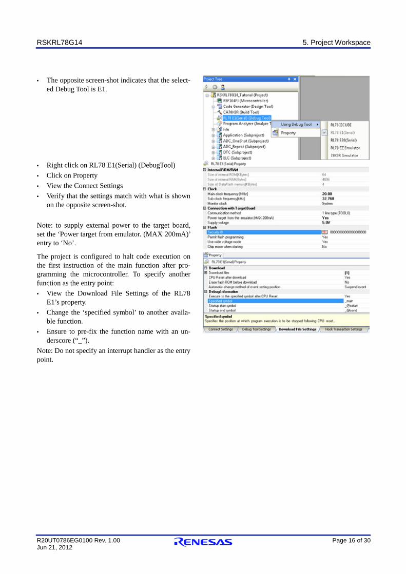
· The opposite screen-shot indicates that the select-
ed Debug Tool is E1.
· Right click on RL78 E1(Serial) (DebugTool) · Click on Property · View the Connect Settings · Verify that the settings match with what is shown
on the opposite screen-shot. Note: to supply external power to the target board, set the ‘Power target from emulator. (MAX 200mA)’ entry to ‘No’.
The project is configured to halt code execution on the first instruction of the main function after pro-gramming the microcontroller. To specify another function as the entry point: · View the Download File Settings of the RL78
E1’s property. · Change the ‘specified symbol’ to another availa-
ble function. · Ensure to pre-fix the function name with an un-
derscore (“_”). Note: Do not specify an interrupt handler as the entry point.
RSKRL78G14 5. Project Workspace
R20UT0786EG0100 Rev. 1.00 Page 17 of 30 Jun 21, 2012
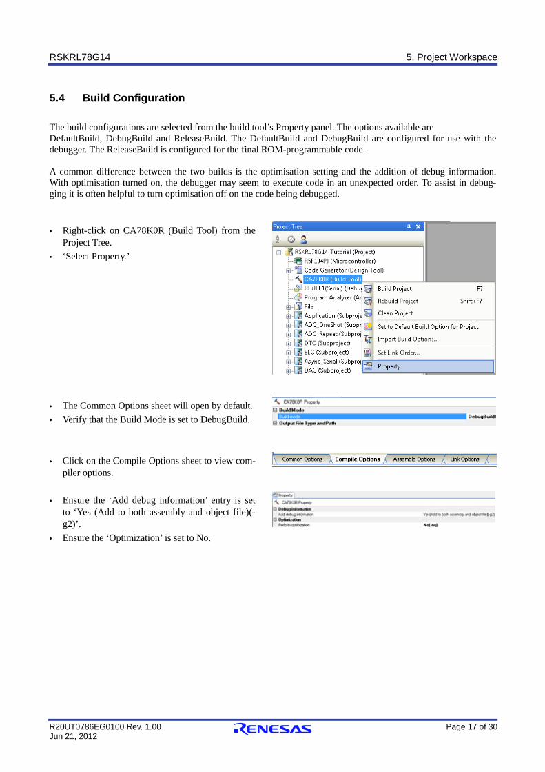
5.4 Build Configuration The build configurations are selected from the build tool’s Property panel. The options available are DefaultBuild, DebugBuild and ReleaseBuild. The DefaultBuild and DebugBuild are configured for use with the debugger. The ReleaseBuild is configured for the final ROM-programmable code. A common difference between the two builds is the optimisation setting and the addition of debug information. With optimisation turned on, the debugger may seem to execute code in an unexpected order. To assist in debug-ging it is often helpful to turn optimisation off on the code being debugged. · Right-click on CA78K0R (Build Tool) from the
Project Tree. · ‘Select Property.’
· The Common Options sheet will open by default. · Verify that the Build Mode is set to DebugBuild.
· Click on the Compile Options sheet to view com-
piler options.
· Ensure the ‘Add debug information’ entry is set to ‘Yes (Add to both assembly and object file)(-g2)’.
· Ensure the ‘Optimization’ is set to No.
RSKRL78G14 6. Building the Tutorial Program
R20UT0786EG0100 Rev. 1.00 Page 18 of 30 Jun 21, 2012
6. Building the Tutorial Program
The tutorial project build settings have been pre-configured in the toolchain options. To view the toolchain options double-click on CA78K0R (Build Tool) from the Project Tree and select the available tabs. It is important when changing settings to be aware of the current configuration before modifying the settings. · Review the options on each of the tabs to be aware
of the options available. For the purposes of the tu-torial, leave all options at default.
· When complete, the Property panel can be closed by clicking [x] on the right-hand corner of the Property window.
6.1 Building the Code There is a choice of three shortcuts available for building the project. · Selecting the ‘Build Project’ toolbar button will build all projects listed in the project tree. · Pressing [F7]. This is equivalent to pressing the ‘Build Project’ toolbar button.
F7
· Selecting the ‘Rebuild Project’ toolbar button will rebuild all project files.
· Selecting the ‘Build & Download’ toolbar button will only build the active project and download the code to the target device after a successful build.
· Pressing [F6]. This is equivalent to pressing the ‘Build & Download’ toolbar button.
F6
Build the project now by pressing [F7] or pressing one of the build icons as shown above. During the build each stage will be reported in the Output Window. The build will complete with an indication of any errors and warnings encountered during the build.
RSKRL78G14 6. Building the Tutorial Program
R20UT0786EG0100 Rev. 1.00 Page 19 of 30 Jun 21, 2012
6.2 Connecting the Debugger For this tutorial it is not necessary to provide an external power supply to the board. The power will be obtained from the USB port. Please be aware that if you have too many devices connected to your USB port it may be shut down by Windows. If this happens remove some devices and try again. Alternatively provide an external power source taking care to ensure the correct polarity and voltage.
The Quick Start Guide provided with the Renesas Starter Kit board gives detailed instructions on how to connect the E1 to the host computer. The following assumes that the steps in the Quick Start Guide have been followed and the E1 drivers have been installed. · Fit the LCD module to LCD connector on the board, via the header marked ‘LCD’. Ensure all the pins of the
connector are correctly inserted in the socket. · Connect the E1 Debugger to a free USB port on your computer. · Connect the E1 Debugger to the target hardware ensuring that it is plugged into the connector marked ‘E1’. · If supplying external power to the board please refer to Section 5.3 to turn off the option of supplying power
from the E1 before turning on the external power supply.
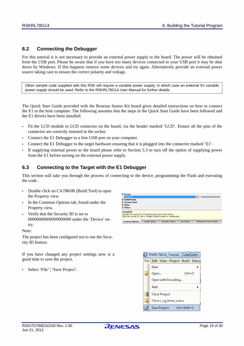
6.3 Connecting to the Target with the E1 Debugger This section will take you through the process of connecting to the device, programming the Flash and executing the code. · Double click on CA78K0R (Build Tool) to open
the Property view. · In the Common Options tab; found under the
Property view. · Verify that the Security ID is set to
00000000000000000000 under the ‘Device’ en-try.
Note: The project has been configured not to use the Secu-rity ID feature.
If you have changed any project settings now is a good time to save the project. · Select ‘File’ | ‘Save Project’.
Other sample code supplied with this RSK will require a variable power supply; in which case an external 5V variable power supply should be used. Refer to the RSKRL78G14 User Manual for further details.
RSKRL78G14 6. Building the Tutorial Program
R20UT0786EG0100 Rev. 1.00 Page 20 of 30 Jun 21, 2012
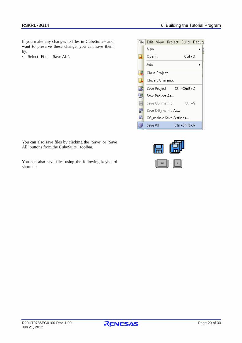
If you make any changes to files in CubeSuite+ and want to preserve these change, you can save them by: · Select ‘File’ | ‘Save All’.
You can also save files by clicking the ‘Save’ or ‘Save All’ buttons from the CubeSuite+ toolbar.
You can also save files using the following keyboard shortcut:
SCtrl +
RSKRL78G14 7. Downloading and Running the Tutorial
R20UT0786EG0100 Rev. 1.00 Page 21 of 30 Jun 21, 2012
7. Downloading and Running the Tutorial
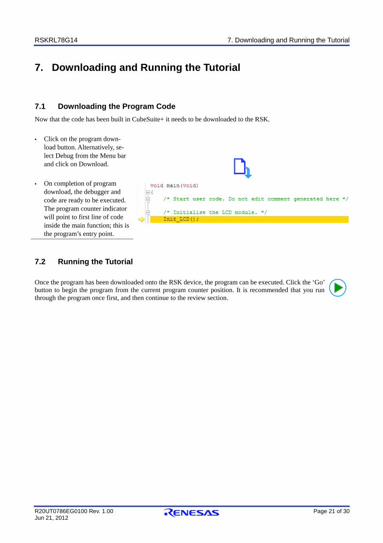
7.1 Downloading the Program Code Now that the code has been built in CubeSuite+ it needs to be downloaded to the RSK.
· Click on the program down-load button. Alternatively, se-lect Debug from the Menu bar and click on Download.
· On completion of program
download, the debugger and code are ready to be executed. The program counter indicator will point to first line of code inside the main function; this is the program’s entry point.
7.2 Running the Tutorial Once the program has been downloaded onto the RSK device, the program can be executed. Click the ‘Go’ button to begin the program from the current program counter position. It is recommended that you run through the program once first, and then continue to the review section.
RSKRL78G14 8. Reviewing the Tutorial Program
R20UT0786EG0100 Rev. 1.00 Page 22 of 30 Jun 21, 2012
8. Reviewing the Tutorial Program This section will look at each section of the tutorial code, how it works, and how it could be altered to be imple-mented into more complex code.
8.1 Program Initialisation Before the main program can run, the microcontroller must be configured. Due to the debugger configuration used for the Tutorial project and the rest of the sample projects, the user will not be able to step through the hardware initialisation code as a result. Please refer to Section 5.3 to change the entry point after programming the microcon-troller. Specify ‘_R_Systeminit’ as the function name if viewing of hardware initialisation is desired. The initialisa-tion code is executed every time the device is reset via the reset switch or from a power reboot. The user is advised not to use the ‘step’ feature of the debugger to exit the R_Systeminit function.
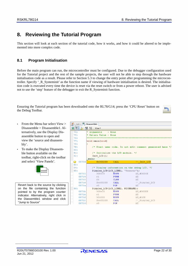
Ensuring the Tutorial program has been downloaded onto the RL78/G14; press the ‘CPU Reset’ button on the Debug Toolbar.
· From the Menu bar select View > Disassemble > Disassemble1. Al-ternatively, use the Display Dis-assemble button to open and view the ‘source and disassem-bly’.
· To make the Display Disassem-ble button available on the toolbar, right-click on the toolbar and select ‘View Panels’.
Revert back to the source by clicking on the file containing the function pointed to by the program counter indicator. Alternatively, right click in the Diassemble1 window and click "Jump to Source"
RSKRL78G14 8. Reviewing the Tutorial Program
R20UT0786EG0100 Rev. 1.00 Page 23 of 30 Jun 21, 2012
8.2 Main Functions This section will look at the program code called from with the main() function, and how it works.
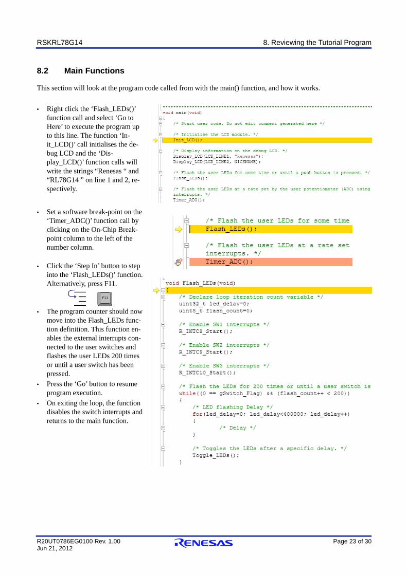
· Right click the ‘Flash_LEDs()’ function call and select ‘Go to Here’ to execute the program up to this line. The function ‘In-it_LCD()’ call initialises the de-bug LCD and the ‘Dis-play_LCD()’ function calls will write the strings “Renesas “ and “RL78G14 ” on line 1 and 2, re-spectively.
· Set a software break-point on the
‘Timer_ADC()’ function call by clicking on the On-Chip Break-point column to the left of the number column.
· Click the ‘Step In’ button to step
into the ‘Flash_LEDs()’ function. Alternatively, press F11.
F11
· The program counter should now
move into the Flash_LEDs func-tion definition. This function en-ables the external interrupts con-nected to the user switches and flashes the user LEDs 200 times or until a user switch has been pressed.
· Press the ‘Go’ button to resume program execution.
· On exiting the loop, the function disables the switch interrupts and returns to the main function.
RSKRL78G14 8. Reviewing the Tutorial Program
R20UT0786EG0100 Rev. 1.00 Page 24 of 30 Jun 21, 2012
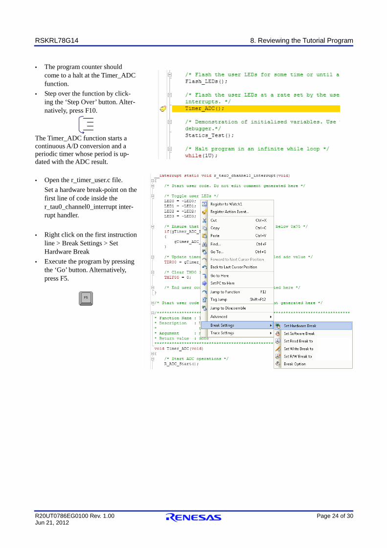
· The program counter should come to a halt at the Timer_ADC function.
· Step over the function by click-ing the ‘Step Over’ button. Alter-natively, press F10.
The Timer_ADC function starts a continuous A/D conversion and a periodic timer whose period is up-dated with the ADC result.
· Open the r_timer_user.c file.
Set a hardware break-point on the first line of code inside the r_tau0_channel0_interrupt inter-rupt handler.
· Right click on the first instruction line > Break Settings > Set Hardware Break
· Execute the program by pressing the ‘Go’ button. Alternatively, press F5.
F5
RSKRL78G14 8. Reviewing the Tutorial Program
R20UT0786EG0100 Rev. 1.00 Page 25 of 30 Jun 21, 2012
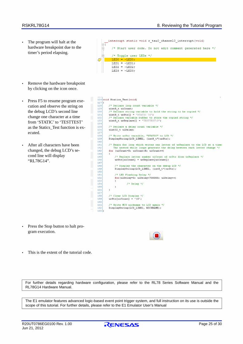
· The program will halt at the hardware breakpoint due to the timer’s period elapsing.
· Remove the hardware breakpoint
by clicking on the icon once. · Press F5 to resume program exe-
cution and observe the string on the debug LCD’s second line change one character at a time from ‘STATIC’ to ‘TESTTEST’ as the Statics_Test function is ex-ecuted.
· After all characters have been
changed, the debug LCD’s se-cond line will display “RL78G14”.
· Press the Stop button to halt pro-gram execution.
· This is the extent of the tutorial code.
For further details regarding hardware configuration, please refer to the RL78 Series Software Manual and the RL78G14 Hardware Manual.
The E1 emulator features advanced logic-based event point trigger system, and full instruction on its use is outside the scope of this tutorial. For further details, please refer to the E1 Emulator User’s Manual
RSKRL78G14 9. Additional Information
R20UT0786EG0100 Rev. 1.00 Page 26 of 30 Jun 21, 2012
9. Additional Information
Technical Support For details on how to use CubeSuite+, refer to [Help > Tutorial] from the menu bar within the CubeSuite+. For information about the RL78/G14 microcontrollers refer to the RL78/G14 Group hardware manual. For information about the RL78/G14 assembly language, refer to [Help > Tutorial] from the menu bar within the CubeSuite+. Online technical support and information is available at: http://www.renesas.com/rskrl78g14 Technical Contact Details [email protected] General information on Renesas Microcontrollers can be found on the Renesas website at: http://www.renesas.com/ Trademarks All brand or product names used in this manual are trademarks or registered trademarks of their respective com-panies or organisations. Copyright This document may be, wholly or partially, subject to change without notice. All rights reserved. Duplication of this document, either in whole or part is prohibited without the written permission of Renesas Electronics Europe Lim-ited. © 2012 Renesas Electronics Europe Limited. All rights reserved. © 2012 Renesas Electronics Corporation. All rights reserved. © 2012 Renesas Solutions Corp. All rights reserved.

REVISION HISTORY RSKRL78G14 Tutorial Manual
Rev. Date Description Page Summary
1.00 Jun 21, 2012 ¾ First Edition issued

Renesas Starter Kit Tutorial Manual Publication Date: Rev.1.00 Jun 21, 2012 Published by: Renesas Electronics Corporation
SALES OFFICES http://www.renesas.com Refer to "http://www.renesas.com/" for the latest and detailed information. Renesas Electronics America Inc. 2880 Scott Boulevard Santa Clara, CA 95050-2554, U.S.A. Tel: +1-408-588-6000, Fax: +1-408-588-6130 Renesas Electronics Canada Limited 1101 Nicholson Road, Newmarket, Ontario L3Y 9C3, Canada Tel: +1-905-898-5441, Fax: +1-905-898-3220 Renesas Electronics Europe Limited Dukes Meadow, Millboard Road, Bourne End, Buckinghamshire, SL8 5FH, U.K Tel: +44-1628-585-100, Fax: +44-1628-585-900 Renesas Electronics Europe GmbH Arcadiastrasse 10, 40472 Düsseldorf, Germany Tel: +49-211-65030, Fax: +49-211-6503-1327 Renesas Electronics (China) Co., Ltd. 7th Floor, Quantum Plaza, No.27 ZhiChunLu Haidian District, Beijing 100083, P.R.China Tel: +86-10-8235-1155, Fax: +86-10-8235-7679 Renesas Electronics (Shanghai) Co., Ltd. Unit 204, 205, AZIA Center, No.1233 Lujiazui Ring Rd., Pudong District, Shanghai 200120, China Tel: +86-21-5877-1818, Fax: +86-21-6887-7858 / -7898 Renesas Electronics Hong Kong Limited Unit 1601-1613, 16/F., Tower 2, Grand Century Place, 193 Prince Edward Road West, Mongkok, Kowloon, Hong Kong Tel: +852-2886-9318, Fax: +852 2886-9022/9044 Renesas Electronics Taiwan Co., Ltd. 7F, No. 363 Fu Shing North Road Taipei, Taiwan Tel: +886-2-8175-9600, Fax: +886 2-8175-9670 Renesas Electronics Singapore Pte. Ltd. 1 harbourFront Avenue, #06-10, keppel Bay Tower, Singapore 098632 Tel: +65-6213-0200, Fax: +65-6278-8001 Renesas Electronics Malaysia Sdn.Bhd. Unit 906, Block B, Menara Amcorp, Amcorp Trade Centre, No. 18, Jln Persiaran Barat, 46050 Petaling Jaya, Selangor Darul Ehsan, Malaysia Tel: +60-3-7955-9390, Fax: +60-3-7955-9510 Renesas Electronics Korea Co., Ltd. 11F., Samik Lavied' or Bldg., 720-2 Yeoksam-Dong, Kangnam-Ku, Seoul 135-080, Korea Tel: +82-2-558-3737, Fax: +82-2-558-5141
© 2012 Renesas Electronics Corporation. All rights reserved. Colophon 1.0
R20UT0786EG0100
RL78/G14 Group