Embed Size (px)
Citation preview
All rights reserved.Reproduction in whole or in part is prohibited without the prior written permission of the copyright holder.
May 2007
Regulatory and Compliance Standards for RF Devices
White Paper
Revision 1.0 Page 2 of 21
White Paper
Liability disclaimer
Nordic Semiconductor ASA reserves the right to make changes without further notice to the product to improve reliability, function or design. Nordic Semiconductor ASA does not assume any liability arising out of the application or use of any product or circuits described herein.
Life support applications
These products are not designed for use in life support appliances, devices, or systems where malfunction of these products can reasonably be expected to result in personal injury. Nordic Semiconductor ASA cus-tomers using or selling these products for use in such applications do so at their own risk and agree to fully indemnify Nordic Semiconductor ASA for any damages resulting from such improper use or sale.
Contact details
For your nearest dealer, please see http://www.nordicsemi.no
Receive available updates automatically by subscribing to eNews from our homepage or check our web-site regularly for any available updates.
Main office:
Otto Nielsens vei 127004 Trondheim
Phone: +47 72 89 89 00 Fax: +47 72 89 89 89www.nordicsemi.no
Revision History
Date Version DescriptionMay 2007 1.0
Revision 1.0 Page 3 of 21
Regulatory and Compliance Standards forRF Devices
Contents
1 Introduction ............................................................................................... 42 FCC............................................................................................................. 62.1 Spurious emissions and restricted bands ............................................ 62.2 Receivers ............................................................................................. 62.3 Periodic applications ............................................................................ 72.4 The 915MHz band................................................................................ 82.5 The 2.4GHz band................................................................................. 83 ETSI ............................................................................................................ 103.1 Frequency plan .................................................................................... 103.2 Below 1GHz .........................................................................................113.2.1 Receivers.........................................................................................113.2.2 Transmitters..................................................................................... 113.3 Usable frequencies for the nRF9x5......................................................123.4 The 2.4GHz band................................................................................. 124 Other regulatory standards...................................................................... 144.1 ARIB..................................................................................................... 144.2 Australian/New Zealand Standard ....................................................... 144.3 Korea.................................................................................................... 155 Measurements on Nordic radios .............................................................165.1 Emission conversion ............................................................................ 165.2 General measurement procedure ........................................................ 165.3 Common measurements mistakes....................................................... 185.3.1 Spectrum analyzer resolution Bandwidth ........................................185.3.2 Intermodulation................................................................................ 195.3.3 Application specific standards ......................................................... 206 Preparation for test ................................................................................... 217 Further information................................................................................... 22
White Paper
1 Introduction
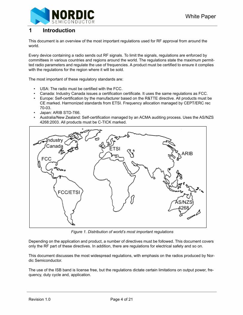
This document is an overview of the most important regulations used for RF approval from around the world.
Every device containing a radio sends out RF signals. To limit the signals, regulations are enforced by committees in various countries and regions around the world. The regulations state the maximum permit-ted radio parameters and regulate the use of frequencies. A product must be certified to ensure it complies with the regulations for the region where it will be sold.
The most important of these regulatory standards are:
• USA: The radio must be certified with the FCC.• Canada: Industry Canada issues a certification certificate. It uses the same regulations as FCC.• Europe: Self-certification by the manufacturer based on the R&TTE directive. All products must be
CE marked. Harmonized standards from ETSI. Frequency allocation managed by CEPT/ERC rec 70-03.
• Japan: ARIB STD-T66.• Australia/New Zealand: Self-certification managed by an ACMA auditing process. Uses the AS/NZS
4268:2003. All products must be C-TICK marked.
Figure 1. Distribution of world’s most important regulations
Depending on the application and product, a number of directives must be followed. This document covers only the RF part of these directives. In addition, there are regulations for electrical safety and so on.
This document discusses the most widespread regulations, with emphasis on the radios produced by Nor-dic Semiconductor.
The use of the ISB band is license free, but the regulations dictate certain limitations on output power, fre-quency, duty cycle and, application.
IndustryCanada
FCC
ETSI
FCC/ETSI
ARIB
AS/NZS 4268
Revision 1.0 Page 4 of 21
Regulatory and Compliance Standards forRF Devices
When the product is finished, a EMC (Electomagnetic Compability) test lab must be contacted to conduct the testing. They perform a series of measurements and declare if the product is approved. It is useful to do measurements in the design phase to make the product easier to pass the approval. This document includes some guidelines on how to do such measurements.
It is the finished product that must be approved by the appropriate regulative authorities. This means your product must have the finished housing, PCB and, firmware. This can not be changed after the approval is given. It also means that the radio chip can not be approved individually. There is an exception for modules that have an FCC approval, but some tests are still necessary on the finished product.
Note: The information found in this document can be changed at any time by the different regulative authorities so check the details in the newest official regulations or standards.
Note: Nordic Semiconductor does not take any responsibility for the consequences of usage of this information. All information is believed to be correct at the time of writing.
Revision 1.0 Page 5 of 21
White Paper
2 FCC
In the USA, the FCC (Federal Communications Commission) regulates the use of frequencies for RF equipment. CFR 47 part 15 (Code of Federal Regulations) covers the unlicensed ISM bands. This is usu-ally referred to as FCC part 15. All equipment must be certified with the FCC with the issuance of a Grant of Authorization by the FCC. When the product is approved, the FCC issues an identification number which the product must be marked with.
The part 15 sections for ISM band radios are:
• 15.35: General rules for certification measurements• 15.109: Radiated emission limits for unintentional radiators• 15.205: Restricted bands of operation• 15.209: Radiation limits for intentional radiators• 15.231: Periodic operation in the band 40.66 - 40.70 MHz and above 70 MHz.• 15.247: Frequency Hopping and Spread Spectrum (FHSS), operation within the bands 902 –
928MHz, 2400 – 2483.5 MHz• 15.249: Single frequency systems and non FHSS systems, operation within the bands 902 –
928MHz, 2400 – 2483.5 MHz
2.1 Spurious emissions and restricted bands
A large part of the FCC Part 15 is about the limit of spurious emissions (harmonic component) and restricted bands.
The main concept behind part 15 is that a general set of rules must be followed, but with exceptions for dif-ferent application and frequency bands.
Emissions are divided into two parts:
• Unintended radiators, like receivers and transmitters in standby or other radiators.• Intended radiators, like active transmitters.
2.2 Receivers
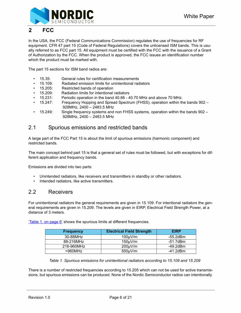
For unintentional radiators the general requirements are given in 15.109. For intentional radiators the gen-eral requirements are given in 15.209. The levels are given in EIRP, Electrical Field Strength Power, at a distance of 3 meters.
’Table 1. on page 6’ shows the spurious limits at different frequencies.
Table 1. Spurious emissions for unintentional radiators according to 15.109 and 15.209
There is a number of restricted frequencies according to 15.205 which can not be used for active transmis-sions, but spurious emissions can be produced. None of the Nordic Semiconductor radios can intentionally
Frequency Electrical Field Strength EIRP30-88MHz 100µV/m -55.2dBm88-216MHz 150µV/m -51.7dBm216-960MHz 200µV/m -49.2dBm
>960MHz 500µV/m -41.2dBm
Revision 1.0 Page 6 of 21
Regulatory and Compliance Standards forRF Devices
transmit in any of these frequencies but, care must be taken if spurious or harmonics falls into these fre-quency bands.
2.3 Periodic applications
Section 15.231(a) covers Periodic operation in the band 40.66 - 40.70 MHz and above 70 MHz.
The provisions of this section are restricted to periodic operation within the band 40.66 - 40.70 MHz and above 70 MHz. The intentional radiator is restricted to the transmission of a control signal such as those used with alarm systems, door openers, remote switches, and so on. Continuous transmissions, voice, video and the radio control of toys are not permitted. Data is permitted to be sent with a control signal.
The following conditions must be met:
• A manually operated transmitter shall employ a switch that automatically deactivates the transmitter within not more than 5 seconds of being released.
• A transmitter activated automatically shall cease transmission within 5 seconds after activation.• Periodic transmissions at regular predetermined intervals are not permitted. However, polling or
supervision transmissions, including data, to determine system integrity of transmitters used in security or safety applications are allowed if the total duration of transmissions does not exceed more than two seconds per hour for each transmitter. There is no limit on the number of individual transmissions, provided the total transmission time does not exceed two seconds per hour.
• Transmitters which are employed for radio control purposes during emergencies involving fire, secu-rity, and safety of life, when activated to signal an alarm, may operate during the pendency of the alarm condition.
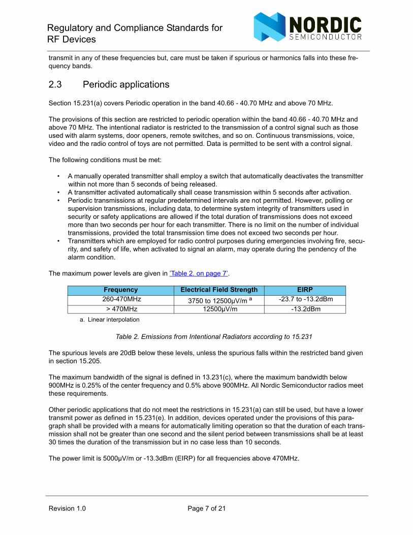
The maximum power levels are given in ’Table 2. on page 7’.
Table 2. Emissions from Intentional Radiators according to 15.231
The spurious levels are 20dB below these levels, unless the spurious falls within the restricted band given in section 15.205.
The maximum bandwidth of the signal is defined in 13.231(c), where the maximum bandwidth below 900MHz is 0.25% of the center frequency and 0.5% above 900MHz. All Nordic Semiconductor radios meet these requirements.
Other periodic applications that do not meet the restrictions in 15.231(a) can still be used, but have a lower transmit power as defined in 15.231(e). In addition, devices operated under the provisions of this para-graph shall be provided with a means for automatically limiting operation so that the duration of each trans-mission shall not be greater than one second and the silent period between transmissions shall be at least 30 times the duration of the transmission but in no case less than 10 seconds.
The power limit is 5000µV/m or -13.3dBm (EIRP) for all frequencies above 470MHz.
Frequency Electrical Field Strength EIRP260-470MHz 3750 to 12500µV/m a
a. Linear interpolation
-23.7 to -13.2dBm> 470MHz 12500µV/m -13.2dBm
Revision 1.0 Page 7 of 21
White Paper
2.4 The 915MHz band
The nRF9x5 radio can operate in the 433, 868 and, 915MHz bands. ’Table 2. on page 7’ shows that using these bands allows very low output power. But section 15.249 gives the opportunity to use the 902-928MHz band with a higher output power, 50mV/m at 3 meters or -1.2dBm. The harmonics are limited to 500µV/m or -41.2dBm. This band is commonly referred to as the 915MHz band in the USA. There are no restrictions on duty cycle or the application.
Even higher output power can be used according to section 15.247. This implies the use of frequency hop-ping. The following requirements must be fulfilled for the use of the 902-928MHz band under section 15.247:
• Hopping channels shall be separated by minimum 25 kHz or the 20dB bandwdith of the hopping channel, whichever is greater.
• The system shall hop to channel frequencies that are selected at the system hopping rate from a pseudorandomly ordered list of hopping frequencies.
• If the 20 dB bandwidth of the hopping channel is less than 250 kHz, the system shall use at least 50 hopping frequencies and the average time of occupancy on any frequency shall not be greater than 0.4 seconds within a 20 second period.
• If the 20 dB bandwidth of the hopping channel is 250 kHz or greater, the system shall use at least 25 hopping frequencies and the average time of occupancy on any frequency shall not be greater than 0.4 seconds within a 10 second period.
• The maximum allowed 20 dB bandwidth of the hopping channel is 500 kHz.
The nRF905 has a 20dB bandwidth of a little more than 200 kHz. This means that the channel separation shall be more than 200 kHz. The closest is 400 kHz, giving 65 hopping channels in the 902-928MHz band.
Maximum peak conducted output power is 1W in the 902-928MHz band if more than 50 hopping channels are used. The limit is 0.125W for 25 to 50 hopping channels.
2.5 The 2.4GHz band
The same two sections, 15.247 and 15.249 apply for the 2.4 GHz band. The permitted frequency is 2400 to 2483.5MHz.
For non-frequency hopping systems (15.249), the power limit is 50mV/m at 3 meters or -1.2dBm and the harmonics are limited to 500µV/m or -41.2dBm. The latter also applies for the radiation outside the fre-quency band (15.109). Remember that transmissions close to the band edge causes a too high level out-side the band. It is therefore necessary to avoid using channels close to the band edge.
15.249(e) states that the field strength limits for frequencies above 1GHz are based on average limits. However, the peak field strength of any emission shall not exceed the maximum permitted average limits specified above by more than 20 dB under any condition of modulation.
This means that the permitted output power and the harmonics levels can be increased with up to 20dB depending on the duty cycle, after the following formula:
where Ton is the time of transmission and Toff is the pause between trans-missions.
⎟⎟⎠
⎞⎜⎜⎝
⎛
+=
offon
onincrease TT
TP log20
Revision 1.0 Page 8 of 21
Regulatory and Compliance Standards forRF Devices
Section 15.247 also applies for the 2.4GHz band. The nRF24xx series of radios have a channel spacing of 1MHz. This gives the following requirements for operation under section 15.247:
• Frequency hopping systems operating in the 2400-2483.5 MHz band may have hopping channel carrier frequencies that are separated by 25 kHz or two-thirds of the 20 dB bandwidth of the hopping channel, whichever is greater, provided the systems operate with an output power no greater than 125 mW.
• The system shall hop to channel frequencies that are selected at the system hopping rate from a pseudorandomly ordered list of hopping frequencies.
• Frequency hopping systems in the 2400-2483.5 MHz band shall use at least 15 channels. The aver-age time of occupancy on any channel shall not be greater than 0.4 seconds within a period of 0.4 seconds multiplied by the number of hopping channels employed. Frequency hopping systems may avoid or suppress transmissions on a particular hopping frequency provided that a minimum of 15 channels are used.
• Maximum peak conducted power for systems with more than 75 non overlapping hopping channels is 1W (+30dBm) and 0.125W (+20.9dBm)
Harmonics must be 20dB below the peak in-band emission in any 100 kHz bandwidth for FHSS systems.
Note: Section 15.247 (a)(2) specifies “Systems using digital modulation techniques may operate in the 902 - 928 MHz, 2400 - 2483.5 MHz, and 5725 - 5850 MHz bands. The minimum 6 dB bandwidth shall be at least 500kHz”. Digital modulation is here DSSS (Direct Sequence Spread Spectrum) and does not apply for the Nordic Semiconductor radios.
Revision 1.0 Page 9 of 21
White Paper
3 ETSI
In Europe, the procedure of qualification of wireless equipment in the European Economic Area is explained in the R&TTE directive (Directive 199/5/EC of the European Parliament and Council). The stan-dards used to define tests and requirements are made by standardisation bodies, like CEPT (The Euro-pean Conference of Postal and Telecommunications Administration) and ETSI (European Telecommunications Standards Institute).
Low power devices are referred to as Short Range Devices (SRD).
CEPT has responsibility for frequency allocation and the use of the different bands. This is covered by ERC (European Radiocommunications Committee) recommendation CEPT/ERC 70-03.
ETSI develops and administrates standards for testing and type approval of RF equipment.
General EMC requirements for RF equipment are outlined in EN 300 683 or EN 301 489-3.
The most used ETSI standards for SRD radios are:
• EN 300 220 – 25MHz to 1GHz• EN 300 440 – 1 to 40GHz• EN 300 328 – 2.4GHz, Frequency hopping / Spread Spectrum
The manufacturer must self-declare that the product complies with the R&TTE directive in order to mark it with the CE logo.
3.1 Frequency plan
The frequency plan used in the European countries for SRD radios are covered in the CEPT/ERC rec 70-03. The CEPT member countries must ratify the recommendation but there can be different frequency lim-its between CEPT member countries.
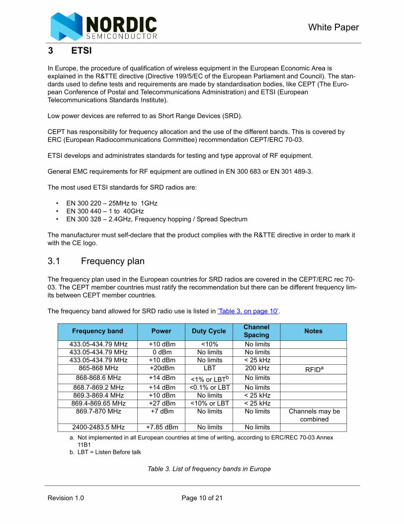
The frequency band allowed for SRD radio use is listed in ’Table 3. on page 10’.
Table 3. List of frequency bands in Europe
Frequency band Power Duty Cycle Channel Spacing Notes
433.05-434.79 MHz +10 dBm <10% No limits433.05-434.79 MHz 0 dBm No limits No limits433.05-434.79 MHz +10 dBm No limits < 25 kHz
865-868 MHz +20dBm LBT 200 kHz RFIDa
a. Not implemented in all European countries at time of writing, according to ERC/REC 70-03 Annex 11B1
868-868.6 MHz +14 dBm <1% or LBTb
b. LBT = Listen Before talk
No limits868.7-869.2 MHz +14 dBm <0.1% or LBT No limits869.3-869.4 MHz +10 dBm No limits < 25 kHz869.4-869.65 MHz +27 dBm <10% or LBT < 25 kHz
869.7-870 MHz +7 dBm No limits No limits Channels may be combined
2400-2483.5 MHz +7.85 dBm No limits No limits
Revision 1.0 Page 10 of 21
Regulatory and Compliance Standards forRF Devices
3.2 Below 1GHz
The ETSI EN 300 220 defines the method of measurements for frequencies below 1GHz.
3.2.1 Receivers
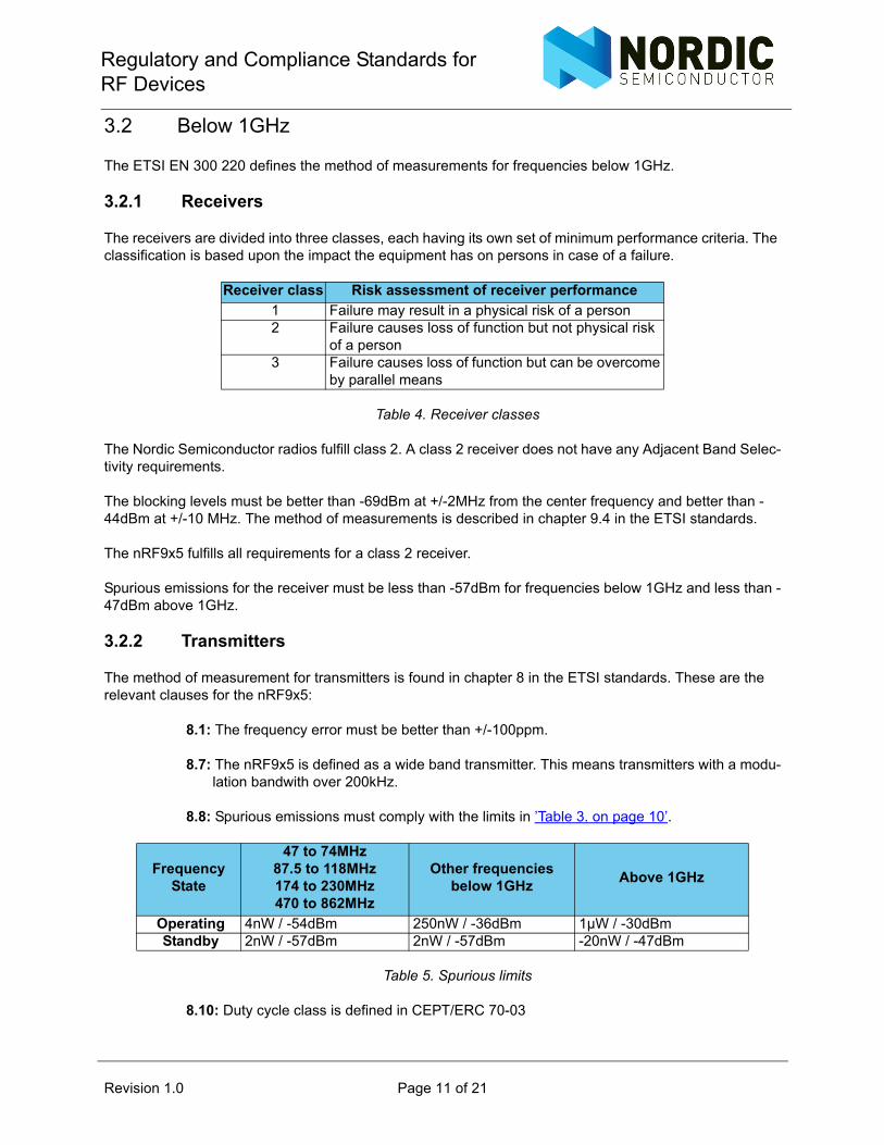
The receivers are divided into three classes, each having its own set of minimum performance criteria. The classification is based upon the impact the equipment has on persons in case of a failure.
Table 4. Receiver classes
The Nordic Semiconductor radios fulfill class 2. A class 2 receiver does not have any Adjacent Band Selec-tivity requirements.
The blocking levels must be better than -69dBm at +/-2MHz from the center frequency and better than -44dBm at +/-10 MHz. The method of measurements is described in chapter 9.4 in the ETSI standards.
The nRF9x5 fulfills all requirements for a class 2 receiver.
Spurious emissions for the receiver must be less than -57dBm for frequencies below 1GHz and less than -47dBm above 1GHz.
3.2.2 Transmitters
The method of measurement for transmitters is found in chapter 8 in the ETSI standards. These are the relevant clauses for the nRF9x5:
8.1: The frequency error must be better than +/-100ppm.
8.7: The nRF9x5 is defined as a wide band transmitter. This means transmitters with a modu-lation bandwith over 200kHz.
8.8: Spurious emissions must comply with the limits in ’Table 3. on page 10’.
Table 5. Spurious limits
8.10: Duty cycle class is defined in CEPT/ERC 70-03
Receiver class Risk assessment of receiver performance1 Failure may result in a physical risk of a person2 Failure causes loss of function but not physical risk
of a person3 Failure causes loss of function but can be overcome
by parallel means
Frequency State
47 to 74MHz87.5 to 118MHz174 to 230MHz470 to 862MHz
Other frequencies below 1GHz Above 1GHz
Operating 4nW / -54dBm 250nW / -36dBm 1µW / -30dBmStandby 2nW / -57dBm 2nW / -57dBm -20nW / -47dBm
Revision 1.0 Page 11 of 21
White Paper
8.11: Listen before talk (LBT)
If the transmitters use LBT, the duty cycle requirement does not apply. The principle is to use the receiver to see if the channel is clear before a transmission is started. The Carrier Detect function of the nRF9x5 can be used for this. The following requirements must be fulfilled:
• The receiver must have a LTB threshold defined in clause 9.2.• The receiver blocking requirements in clause 9.4.• Minimum TX off time is 100ms.• The total listen time, tL, concists of a fixed part, tF, and a pseudorandom part, tPS, as the following:
tL=tF+tPSThe fixed part is minimum 5ms.The pseudorandom time shall vary between 0ms and 5ms in steps of 0.5ms. If the channel is free at the start of the listening time, and remains free throughout the fixed part of the time, the pseudorandom time can be set to 0.If the channel is occupied at the start of the listening time, or during the period, the pseudo random time must be included to the total listening time. An acknowledge packet can be sent as a receipt for the received message. No listening time is required for this. The limit for a transmission is 1s.The limit for a transmission sequence is 4s.
3.3 Usable frequencies for the nRF9x5
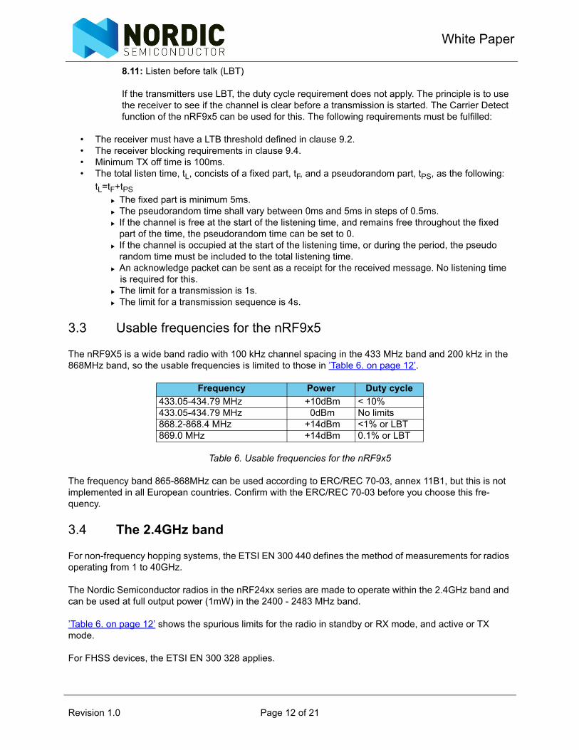
The nRF9X5 is a wide band radio with 100 kHz channel spacing in the 433 MHz band and 200 kHz in the 868MHz band, so the usable frequencies is limited to those in ’Table 6. on page 12’.
Table 6. Usable frequencies for the nRF9x5
The frequency band 865-868MHz can be used according to ERC/REC 70-03, annex 11B1, but this is not implemented in all European countries. Confirm with the ERC/REC 70-03 before you choose this fre-quency.
3.4 The 2.4GHz band
For non-frequency hopping systems, the ETSI EN 300 440 defines the method of measurements for radios operating from 1 to 40GHz.
The Nordic Semiconductor radios in the nRF24xx series are made to operate within the 2.4GHz band and can be used at full output power (1mW) in the 2400 - 2483 MHz band.
’Table 6. on page 12’ shows the spurious limits for the radio in standby or RX mode, and active or TX mode.
For FHSS devices, the ETSI EN 300 328 applies.
Frequency Power Duty cycle433.05-434.79 MHz +10dBm < 10%433.05-434.79 MHz 0dBm No limits868.2-868.4 MHz +14dBm <1% or LBT869.0 MHz +14dBm 0.1% or LBT
Revision 1.0 Page 12 of 21
Regulatory and Compliance Standards forRF Devices
The main requirements for a FHSS system are:
• Make use of minimum 15 non-overlapping channels• Minimum channel separation is 1MHz• Dwell time pr. channel shall not exceed 0.4s• For adaptive FHSS systems, minimum 90% of the band shall be used and minimum 20 channels.
Revision 1.0 Page 13 of 21
White Paper
4 Other regulatory standards
4.1 ARIB
In Japan, the ARIB STD-T66 applies for equipment operating in the 2.4GHz band.
Communication is limited to digital transmission systems, including spread spectrum. The allowed fre-quency band is 2400 to 2483.5MHz.
Maximum allowed output power is 10mW measured in a 1MHz bandwidth for a non-FHSS system. If FHSS is used, maximum power is 3mW measured in a 1MHz bandwidth if the whole band is used. 10mW can be used for FHSS systems, but not from 2.427 to 2.47075GHz, where the limit is 3mW.
The power to the antenna shall be within +20% and -80% of the rated power.
Maximum frequency tolerance is +/-50ppm. This is directly linked to the tolerance of the crystal used on the nRF devices.
Spurious emissions shall be measured on the antenna connector and must be below 25µW / -16dBm inside the band and 2.5µW / -26dBm outside.
Dwell time per channel shall not exceed 0.4s for FHSS systems.
For receivers, the spurious limit is 4nW / -53dBm below 1GHz and 20nW / -47dBm above 1GHz.
4.2 Australian/New Zealand Standard
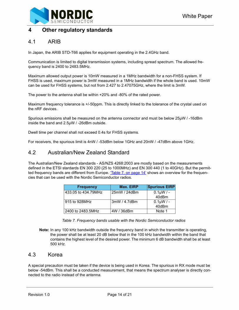
The Australian/New Zealand standards - AS/NZS 4268:2003 are mostly based on the measurements defined in the ETSI stardards EN 300 220 (25 to 1000MHz) and EN 300 440 (1 to 40GHz). But the permit-ted frequency bands are different from Europe. ’Table 7. on page 14’ shows an overview for the frequen-cies that can be used with the Nordic Semiconductor radios.
Table 7. Frequency bands usable with the Nordic Semiconductor radios
Note: In any 100 kHz bandwidth outside the frequency band in which the transmitter is operating, the power shall be at least 20 dB below that in the 100 kHz bandwidth within the band that contains the highest level of the desired power. The minimum 6 dB bandwidth shall be at least 500 kHz.
4.3 Korea
A special precaution must be taken if the device is being used in Korea. The spurious in RX mode must be below -54dBm. This shall be a conducted measurement, that means the spectrum analyser is directly con-nected to the radio instead of the antenna.
Frequency Max. EIRP Spurious EIRP433.05 to 434.79MHz 25mW / 24dBm 0.1µW / -
40dBm915 to 928MHz 3mW / 4.7dBm 0.1µW / -
40dBm2400 to 2483.5MHz 4W / 36dBm Note 1
Revision 1.0 Page 14 of 21
Regulatory and Compliance Standards forRF Devices
5 Measurements on Nordic radios
5.1 Emission conversion
There is a number of ways to specify the radiated power from an antenna. E (Electrical Field Strength) defines the energy in a distance from the antenna. This is highly dependent on the antenna. If the energy is radiated from an ideal, isotropic antenna, where the radiation is uniform in all directions, the power can be expressed as EIRP (Effective Isotropic Radiated Power). If the antenna is a half wave dipol, the same can be expressed as ERP (Effective Radiated Power). It can be useful to convert between E and EIRP since the latter expresses what output power the radio must have to generate an electrical field of a spe-cific strength with an ideal antenna. The following formula can be used to convert between the two:
Where r is the distance, EIRP is in dBm and V is the unit of measurements.
FCC normally states the distance to 3 meters, so the equation can be simplified to:
Where E is the Electrical Field Strength at 3 meter and EIRP is in dBm.
A half wave dipol has a gain that is 2.15dB higher than an isotropic antenna, so:
5.2 General measurement procedure
This section describes how to do initial testing before sending the device to the EMC lab.
To properly test the RF parameters, there are two tests that need to be done:
• TX test for the channels in use, or through the band.• RX test, look for spurious.
The tests should first be conducted, where a coaxial cable is connected to the DUT (Device Under Test) instead of the antenna. If the antenna is connected directly to the matching network, the track needs to be cut. Do not connect the antenna and the coaxial cable in parallel.
If there are components between the matching network and the antenna, they can be removed to discon-nect the antenna.
A spectrum analyzer is connected to the cable. It is recommended to have a spectum analyzer with a max-imum frequency of more than the 4th harmonic.
[ ] [ ]⎟⎟⎠⎞
⎜⎜⎝
⎛=⎟
⎟⎠
⎞⎜⎜⎝
⎛= 2
22
2
22
030.0*log*10
377.0***4
log*10VrE
VrE
EIRPπ
23.95/
log20 −⎟⎟⎠
⎞⎜⎜⎝
⎛=
mVEEIRP
μ
dBEIRPEPR 15.2−=
Revision 1.0 Page 15 of 21
White Paper
The TX is then set to transmit on the chosen channel. If the whole band is to be used, the lowest and high-est channel must be checked, in addition to the middle channel. It can be useful to let the TX sweep through the band.
The transmission can either be packets that are sent as fast as possible or you can set the radio to trans-mit a fixed carrier.
Measure the output power and all the harmonic components. The harmonics can be found at n*fc, where n is an integer and fc is the carrier frequency.
Note the values and compare with the radio standard or regulations. There should be sufficient margins to safely assume the device passes the final test.
The RX test is performed in a similar manner. Here the whole spectrum must be analyzed to see if there is any spurious components above the limit.
In RX mode, there will be some leakage from the local oscillator. The frequency of this is both device spe-cific and dependent on the frequency the RX is set on.
For the nRF9x5, the LO can be found at f0+1MHz. This will be very weak and does not represent an issue you need to monitor.
For the nRF24xx series radios, the LO is found using the equation:
Where fLO is the local oscillator, f0 is the RX frequency and IF is:
• nRF24Z1 IF=4• nRF24L01IF=2• nRF2401, nRF24E1, nRF24AP1 IF=3
All frequencies are in MHz.
You should also conduct the same measurement in an anechoic chamber. This lets you see the effect of the antenna and also lets you check if the board itself radiates.
A real antenna differs from an isotropic antenna. The radiation pattern will in most cases not be circular, but have some gain in one or more directions. At the approval process, the lab will look for the maximum out-put power by turning the device in both the horizontal and vertical plane. Unwanted components can be problematic if the antenna has more than 0dBi gain (gain with reference to an isotropic antenna). This means it is important to have some margins on the regulations to account for the antenna gain.
To measure the frequency accuracy, either a fixed carrier is needed or an inductive probe to measure the crystal. If the crystal reference oscillator is probed, the frequency changes due to the capacitance in the probe. It is a better solution to measure the carrier frequency instead or use an inducive probe and mea-sure the leakage from the oscillator. Such a probe can be made of a coiled wire soldered on the end of a coaxial cable. The coil is held close to the crystal can and a spectrum analyzer is used to measure the fre-quency. For all Nordic Semiconductor radios, the RX and TX frequency is directly connected to the oscilla-tor. It is important that both the TX and RX end of the link uses the exact frequency.
IFff LO += 0*78
Revision 1.0 Page 16 of 21

Regulatory and Compliance Standards forRF Devices
5.3 Common measurements mistakes
5.3.1 Spectrum analyzer resolution bandwidth
When measuring on low level signals, like harmonics and spurious, it is important to adjust the spectrum analyzer so that the signal is well above the noise floor. When the signal is too close to the noise floor, the level will read out higher than it actually is. Decreasing the span and the resolution bandwidth lowers the level of the noise floor and gives more accurate readings. The noise floor should be more than 10dB below the signal. ’Figure 2. on page 17’ shows a signal at 2.4GHz with a level of -70dBm. The signal comes from a signal generator. Using a resolution bandwidth of 100kHz brings the noise floor up to around -72dBm, giving only 2dB margin between the signal and the noise floor. The marker reads out -66.6dBm, an error of 3.4dB.
Figure 2. 2.4GHz signal, -70dBm, RBW=100kHz
Decreasing the resolution bandwidth to 3 kHz brings the noise floor down and the marker reads a correct signal level, see ’Figure 3. on page 18’.
Revision 1.0 Page 17 of 21
White Paper
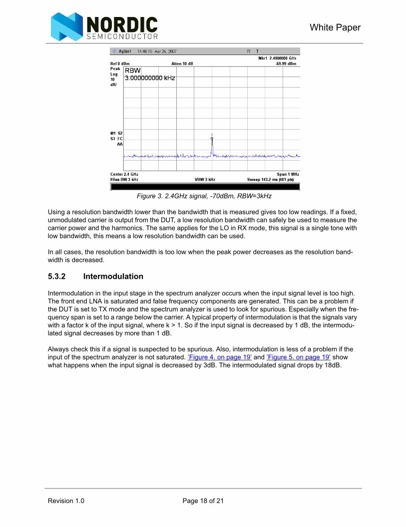
Figure 3. 2.4GHz signal, -70dBm, RBW=3kHz
Using a resolution bandwidth lower than the bandwidth that is measured gives too low readings. If a fixed, unmodulated carrier is output from the DUT, a low resolution bandwidth can safely be used to measure the carrier power and the harmonics. The same applies for the LO in RX mode, this signal is a single tone with low bandwidth, this means a low resolution bandwidth can be used.
In all cases, the resolution bandwidth is too low when the peak power decreases as the resolution band-width is decreased.
5.3.2 Intermodulation
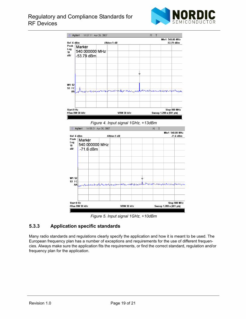
Intermodulation in the input stage in the spectrum analyzer occurs when the input signal level is too high. The front end LNA is saturated and false frequency components are generated. This can be a problem if the DUT is set to TX mode and the spectrum analyzer is used to look for spurious. Especially when the fre-quency span is set to a range below the carrier. A typical property of intermodulation is that the signals vary with a factor k of the input signal, where k > 1. So if the input signal is decreased by 1 dB, the intermodu-lated signal decreases by more than 1 dB.
Always check this if a signal is suspected to be spurious. Also, intermodulation is less of a problem if the input of the spectrum analyzer is not saturated. ’Figure 4. on page 19’ and ’Figure 5. on page 19’ show what happens when the input signal is decreased by 3dB. The intermodulated signal drops by 18dB.
Revision 1.0 Page 18 of 21
Regulatory and Compliance Standards forRF Devices
Figure 4. Input signal 1GHz, +13dBm
Figure 5. Input signal 1GHz, +10dBm
5.3.3 Application specific standards
Many radio standards and regulations clearly specify the application and how it is meant to be used. The European frequency plan has a number of exceptions and requirements for the use of different frequen-cies. Always make sure the application fits the requirements, or find the correct standard, regulation and/or frequency plan for the application.
Revision 1.0 Page 19 of 21
White Paper
6 Preparation for test
Before the device is sent to the test lab, there are a number of things that must be done:
• All hardware and software must be the final version; no changes can be made after qualification.• The PCB must be in the final enclosure or housing.• Some test firmware must be made, it is helpful to have a test mode where the radio is run on differ-
ent channels, usually low, mid and high channels:The TX is set to a fixed carrier at different channel.Modulated carrier, done by sending Shockburst packets as fast as possible.RX in constant on mode.
The normal operation of the equipment must be stated, in case the duty cycle has an impact of the test lim-its.
Some regulation standards require conducted measurements, so an extra device must be delivered with a connector instead of the antenna.
Alternatively, the qualification or test lab should be able to tell you about the information that must be sub-mitted.
Revision 1.0 Page 20 of 21
Regulatory and Compliance Standards forRF Devices
7 Further information
More information regarding the FCC rules and requirements are found at:
http://www.fcc.gov
ETSI standards are found at:
http://www.etsi.org
The CEPT/ERC rec 70-03 are found at:
http://www.ero.dk
The ARIB STD-T66 regulation is found at:
http://www.arib.or.jp/english/index.html
The Australian/New Zealand Standard AS/NZS 4268:2003 are found at:
http://www.standards.org.au
Revision 1.0 Page 21 of 21

![ZigBee PRO Green Power feature. GP Basic functionality set ...infocenter.nordicsemi.com/pdf/15-02016-010-GP_Errata_for_GP_Basic_PICS... · [R6] ZigBee document 064113r08: ZigBee Cluster](https://img.pdfslide.us/doc/110x75/5e1ac48ce0388672b742a31c/zigbee-pro-green-power-feature-gp-basic-functionality-set-r6-zigbee-document.jpg)