Embed Size (px)
Citation preview

Doc. ID 4414_003 v1.2 2017-07-04
nRFready Smart Remote 3 for nRF51User Guide
v1.2

Contents
Doc. ID 4414_003 v1.2 Page 2
Contents
Revision history.................................................................................................................... 4
Chapter 1: Introduction...................................................................................51.1 Smart Remote 3 DK add-on..................................................................................................................................51.2 Smart Remote 3 nRF51 product example....................................................................................................... 5
Chapter 2: Kit content..................................................................................... 72.1 Hardware content..................................................................................................................................................... 72.2 Downloadable content........................................................................................................................................... 8
Chapter 3: Quick start..................................................................................... 93.1 Assemble the Smart Remote 3 hardware........................................................................................................ 93.2 Power up....................................................................................................................................................................103.3 Program your DK with the Smart Remote 3 firmware..............................................................................103.4 Turn on and pair with Windows.......................................................................................................................103.5 Ubuntu setup........................................................................................................................................................... 123.6 Turn on and pair with Ubuntu.......................................................................................................................... 133.7 Configure audio input.......................................................................................................................................... 15
3.7.1 Test voice recognition......................................................................................................................... 163.7.2 Listening to audio quality.................................................................................................................. 17
Chapter 4: System overview......................................................................... 184.1 Remote control........................................................................................................................................................19
4.1.1 Pairing........................................................................................................................................................ 194.1.2 Trackpad....................................................................................................................................................194.1.3 Accelerometer.........................................................................................................................................214.1.4 Free-space navigation..........................................................................................................................224.1.5 Intelligent power saving.....................................................................................................................244.1.6 Keypad....................................................................................................................................................... 244.1.7 Infrared LED............................................................................................................................................. 25
4.2 Firmware upgrading..............................................................................................................................................26
Chapter 5: Hardware description: Smart Remote 3 DK add-on................. 275.1 Hardware figures: Smart Remote 3 DK add-on........................................................................................... 285.2 Block diagram.......................................................................................................................................................... 295.3 Design description................................................................................................................................................. 30
5.3.1 Trackpad....................................................................................................................................................305.3.2 Keypad matrix.........................................................................................................................................315.3.3 Low-power accelerometer circuit................................................................................................... 335.3.4 Motion tracking device....................................................................................................................... 345.3.5 Power supply...........................................................................................................................................355.3.6 Infrared LED and driver.......................................................................................................................365.3.7 Codec......................................................................................................................................................... 365.3.8 Digital microphones (only for use with nRF52 DK)...................................................................375.3.9 nRF51 DK interface............................................................................................................................... 37

Contents
Doc. ID 4414_003 v1.2 Page 3
5.3.10 nRF52 DK interface.............................................................................................................................395.3.11 Current measurement....................................................................................................................... 415.3.12 I2C bus connector............................................................................................................................... 425.3.13 Schematics, bill of materials, PCB layout files, production files......................................... 42
Chapter 6: Hardware description: Smart Remote 3 nRF51 productexample...................................................................................................... 43
6.1 Hardware figures: SR 3 product example......................................................................................................436.2 Block diagram.......................................................................................................................................................... 456.3 Design description................................................................................................................................................. 45
6.3.1 I/O usage...................................................................................................................................................456.3.2 Keypad matrix.........................................................................................................................................466.3.3 Low-power accelerometer circuit................................................................................................... 476.3.4 Motion tracking device....................................................................................................................... 486.3.5 Power supply...........................................................................................................................................496.3.6 Codec......................................................................................................................................................... 506.3.7 Programming interface....................................................................................................................... 516.3.8 Matching network.................................................................................................................................526.3.9 Antenna.....................................................................................................................................................526.3.10 Schematics, bill of materials, PCB layout files, production files......................................... 52
Chapter 7: Firmware update of Smart Remote 3........................................ 547.1 Connect the product example to the nRF51 DK........................................................................................ 547.2 Flash programming................................................................................................................................................557.3 Programming and erasing flash using nRFgo Studio............................................................................... 557.4 Selecting a board to program........................................................................................................................... 567.5 Chip and memory information..........................................................................................................................567.6 Erase all.......................................................................................................................................................................577.7 Programming SoftDevice.....................................................................................................................................577.8 Programming application....................................................................................................................................58
Legal notices....................................................................................................................... 60

Doc. ID 4414_003 v1.2 Page 4
Revision history
Date Version Description
July 2017 1.2 Updated:
• Chapter Hardware description: Smart Remote 3 DK add-on on page27
December 2016 1.1 Created PDF
December 2015 1.0 First release

Doc. ID 4414_003 v1.2 Page 5
Chapter 1
IntroductionThe nRFready Smart Remote 3 reference design for the nRF51 Series (nRF6934) is a low-cost developmentplatform providing a quick and easy starting point for TV remote control applications for Internet-enabled TVs,set-top boxes, and media players. Providing a single-chip solution that is easily implemented, this kit comescomplete with source code and documentation for Bluetooth® low energy applications.
This reference design contains two remote controls, one for development and another for demo purposes.
1.1 Smart Remote 3 DK add-onThe Smart Remote 3 DK add-on (nRF6932) is a board that allows you to connect to the nRF51 Development Kit(nRF51 DK, not included in this kit). Plugging the DK add-on onto the nRF51 DK gives you access to the radiocomponents for developing your remote control design.
Based on the nRF51822 multiprotocol System on Chip (SoC), it is optimized for low-power and low-costapplications and leverages both Bluetooth® low energy and 2.4 GHz proprietary protocols.
Important: The Smart Remote 3 DK add-on (nRF6932) v1.2 and later is compatible with both nRF51and nRF52 development kits.
Features:
• Standard remote control keypad• Motion wakeup detection using low-power accelerometer• 3D motion tracking using gyroscope and InvenSense® motion library• Multi-touch trackpad (supports up to five points of contact)• Voice input using an analog electrostatic microphone (only nRF51)• Voice input using two digital PDM microphones (only nRF52)• Infrared LED for legacy support (only nRF52)• Arduino standard interface for connection to the nRF5x Development Kit• Optimized power management for low power consumption
1.2 Smart Remote 3 nRF51 product exampleThe Smart Remote 3 nRF51 product example (nRF6933) is a fully-designed remote control featuring an analogmicrophone input, a gyroscope, and a typical remote control keypad. It features a subset of the functionalityof the Smart Remote 3 DK add-on, allowing the board to fit nicely into a remote control plastic housing.
Features:
• Standard remote control keypad
1 Introduction
Doc. ID 4414_003 v1.2 Page 6
• Motion wakeup detection using low-power accelerometer• 3D motion tracking using gyroscope and InvenSense® motion library• Voice input using an analog electrostatic microphone• Optimized power management for low power consumption• Powered by two AA batteries• SWD interface connector for programming and debugging

Doc. ID 4414_003 v1.2 Page 7
Chapter 2
Kit contentThe nRFready Smart Remote 3 reference design consists of hardware and access to software components,reference design files, and documentation.
2.1 Hardware contentnRFready Smart Remote 3 reference design hardware consists of the DK add-on, product example, batteriesand a Bluetooth® dongle.
Figure 1: nRFready Smart Remote 3 for nRF51 Series hardware content
2 Kit content
Doc. ID 4414_003 v1.2 Page 8
2.2 Downloadable contentThe nRFready Smart Remote 3 for nRF51 Series reference design includes firmware source code,documentation, hardware schematics, and layout files.
To access these files, go to the Smart Remote 3 for nRF51 web page and follow the instructions given there.
Firmware package
• Firmware for nRFready Smart Remote 3
• Precompiled HEX files• Source code
• nRF51 SDK 9.0.0 (with Keil 5 Packs, and MDK packages for Keil 4 and IAR)• Project files for Keil, ARM®, IAR and ARM GCC• S110 SoftDevice• Nordic Voice System (NVS) package version 4.4 (requires Ubuntu 14.04 LTS)• Firmware documentation (will be available in a folder on your computer after you have run the installer
file)
Hardware files
The zip file and its subdirectories contain the hardware design files for the nRFready Smart Remote 3 for nRF51Series reference design.
• Altium Designer files• Schematics• PCB layout files• Production files
• Drill files• Assembly drawings• Gerber files• Pick-and-place files• Bill of materials
Other relevant nRF51822 documentation
• nRF51 Series Reference Manual• nRF51822 Product Specification• S110 SoftDevice Specification• nRF51822 PAN• nRF51 SDK v9.0.0

Doc. ID 4414_003 v1.2 Page 9
Chapter 3
Quick startSetting up the nRFready Smart Remote 3 reference design requires only a few steps. Example applicationshelp you start programming your device.
Hardware requirements
Additional hardware needed to use the Smart Remote 3 DK add-on:
• nRF51 Development Kit (sold separately)
Operating system requirements
The nRFready Smart Remote 3 complies with the HID-over-GATT profile. The following is needed to set up acomputer as the Bluetooth® low energy host.
• Basic use:
• Windows 8, Windows RT, or Windows 10 for HID-over-GATT standard functions• Linux with Bluetooth® 4.0 support (for example BlueZ 5.0 or later)
• Use with audio:
• Ubuntu 14.04 LTS with Nordic Voice System (NVS) package. See Ubuntu setup on page 12
3.1 Assemble the Smart Remote 3 hardwareUnpack the kit and connect the DK add-on to the nRF51 Development Kit.
1. Unpack your nRFready Smart Remote 3 for nRF51 Series reference design.2. Plug the nRF51 Development Kit (sold separately) carefully in on the backside of the Smart Remote 3 DK
add-on as shown in the figure.

3 Quick start
Doc. ID 4414_003 v1.2 Page 10
3.2 Power upThe Smart Remote 3 for nRF51 product example will be on as soon as the batteries are inserted. The DK add-on can be powered either by the USB or the batteries.
Powering up the add-on requires the following steps:
1. Plug in the USB cable or insert batteries into the battery compartment.
2. If powered by the USB, turn on the power with the power switch. If powered by the batteries it will be on as
soon as the batteries are inserted.
3.3 Program your DK with the Smart Remote 3 firmwareTo use the DK add-on, the nRF51 Development Kit must first be programmed with the firmware. The productexample is preprogrammed, and does not need any programming to get started.
1. Connect the nRF51 DK with DK add-on attached to a computer with a USB cable.
Important: When programming the DK for the first time, it is recommended not to connect theDK add-on hardware, as the DK I/Os are in an unknown state, which may result in overcurrentconsumption.
2. See Firmware update of Smart Remote 3 on page 54 for details on firmware update.
3.4 Turn on and pair with WindowsThe Smart Remote 3 for nRF51 can be connected with Bluetooth® to a host system using Windows.
nRFready Smart Remote will only pair and work with Bluetooth® 4.0 or later, and HID-over-GATT-complianthost systems. The nRFready Smart Remote 3 functionality will vary depending on the supported features inthese platforms.

3 Quick start
Doc. ID 4414_003 v1.2 Page 11
1. If your computer is not Bluetooth® 4.0 enabled, insert the Bluetooth® dongle (supplied) into your computerand wait until the dongle is recognized and the drivers installed properly.
2. Power up the board either by inserting batteries into the battery compartment or by sliding the powerswitch on the DK to ON position (DK add-on only).
3. Pairing mode is automatically selected if Smart Remote 3 was not bound to a previous host. To deleteexisting bonds and to enter into pairing mode, power up Smart Remote 3 while pressing the orangebutton between the Channel + and Volume + buttons.
4. On your computer, navigate to the Bluetooth menu (press the Windows key or open the Start menu and
type Bluetooth).
5. When discovered, you will see Smart Remote 3 in the list over Bluetooth devices. Select it and click Pair to
begin pairing.

3 Quick start
Doc. ID 4414_003 v1.2 Page 12
6. After successfully pairing, the device will show up as connected in the list of Bluetooth devices.
3.5 Ubuntu setupUbuntu LTS has no native support for HID-over-GATT, and therefore you have to first install the Nordic VoiceSystem (NVS) package to support the HID-over-GATT profile.
1. Download the NVS package nvs-4.4.tgz from the Smart Remote 3 for nRF51 start page.2. Open a terminal (CTRL + ALT + T).

3 Quick start
Doc. ID 4414_003 v1.2 Page 13
3. Navigate to the folder where nvs-4.4.tgz is located.4. Unpack the nvs-4.4.tgz file by typing tar -xf nvs-4.4.tgz.5. Open the file nvs-4.4/binaries/HOWTO-install.txt and follow the steps there to complete the
installation.
3.6 Turn on and pair with UbuntuThe Smart Remote 3 for nRF51 can be connected with Bluetooth® to a host system using Ubuntu.
Make sure that you have set up Ubuntu as described in Ubuntu setup on page 12 before you start.
1. If your computer is not Bluetooth® 4.0 enabled, insert the Bluetooth® dongle (supplied) into your computerand wait until the dongle is recognized and the drivers installed properly.
2. Power up the board, either by inserting batteries into the battery compartment, or by sliding the powerswitch on the DK to ON position (DK add-on only).
3. Pairing mode is automatically selected if the Smart Remote 3 was not bound to a previous host. To deleteexisting bonds and enter pairing mode, power up the Smart Remote 3 while pressing the orange buttonbetween between the Channel + and Volume + buttons.
4. On your computer, navigate to the Bluetooth icon and select Bluetooth Settings.

3 Quick start
Doc. ID 4414_003 v1.2 Page 14
5. To search for a new device, click the + button in the Bluetooth window.
6. When discovered, you will see Smart Remote 3 in the Device list. Select it and click Continue to begin
pairing.
7. After successfully pairing, the device will show up connected in the Devices list.

3 Quick start
Doc. ID 4414_003 v1.2 Page 15
3.7 Configure audio inputThe Ubuntu audio settings need to be configured before voice recognition will work.
Before you start, make sure that you have set up Ubuntu as described in Ubuntu setup on page 12.
1. Under All Settings, select Sound and then select the Input tab.2. Select the NVS device from the list of input sources.
Input level should now indicate that it is receiving input.

3 Quick start
Doc. ID 4414_003 v1.2 Page 16
3. To stop streaming, select All Settings or close the window.
3.7.1 Test voice recognitionTo test the voice recognition feature, download and install Google Chrome.
1. Open up Chrome. Select Dash Home and type Google Chrome. Click the Google Chrome icon that isdisplayed.
2. Go to google.com. If you are redirected to a local Google version, click Google.com in the lower-right
corner of the webpage.3. Click the microphone icon. Chrome will stop recording automatically when you stop talking. If you do not
see the microphone icon, the GVoice application might not be installed. Go to the Google Chrome WebStore to download and install GVoice.

3 Quick start
Doc. ID 4414_003 v1.2 Page 17
3.7.2 Listening to audio qualityAudio quality can be verified by looping the sound directly from the Ubuntu input source (Voice InputModule) to the output (speakers).
1. To enable loopback, open a terminal (CTRL + ALT + T).2. In the terminal window, type the following command:
pactl load-module module-loopback latency_msec=20
The command latency_msec=20 is optional. It helps to minimize the acoustic feedback. Somemachines do not accept the command and may return error codes. In that case, just invoke module-loopback without specifying latency.
3. If successful, this command returns a handle number. Invoking this command multiple times generatesmultiple loopback instances with independent handles.
4. To disable the loopback, type the following command in the terminal window:
pactl unload-module x
where x is the handle module number returned when enabling the loopback.
If Smart Remote 3 is not connected and selected as the audio input source, sound will be streamed fromthe computer microphone to the computer speakers causing acoustic feedback.

Doc. ID 4414_003 v1.2 Page 18
Chapter 4
System overviewThis chapter describes the functionality of the remote control including how it can be used for developmentpurposes.
There are two main hardware components in the reference design:
• nRFready Smart Remote 3 DK add-on (nRF6932)• nRFready Smart Remote 3 nRF51 product example (nRF6933)
When the Smart Remote 3 DK add-on (nRF6932) is inserted into a nRF51 DK, you have a functioning remotecontrol (see Assemble the Smart Remote 3 hardware on page 9 for instructions). The term remote controlrefers to the Smart Remote 3 product example (nRF6933) or Smart Remote 3 DK add-on (nRF6932) after it isinserted into the nRF51 DK.
Figure 2: The remote control with a connected TV
Communication in the system is digital and packet-based, which means that data between the remote controland the host is exchanged as discrete packets of information. The nRF device checks the status of the trackpadand the keypad matrix before sending this information to the host. The driver on the computer decodes thepackages allowing you to use the remote control as both a pointing device and keypad.
Important: The term host refers to a Bluetooth® low energy compliant device which supports the HID-over-GATT profile. Windows 10, for instance, natively supports the HID-over-GATT profile providedthere is Bluetooth® low energy hardware connected to the system. A computer with Ubuntu 14.04 LTS,Nordic Voice System (NVS) package and Bluetooth® 4.0 dual-mode (low energy) hardware can also be ahost.
For further details on the software and firmware included, please consult the firmware documentation, codeAPI, or the code itself.

4 System overview
Doc. ID 4414_003 v1.2 Page 19
4.1 Remote controlThe flexibility of the remote control allows you to experiment with your own firmware and functionality. Afterpairing, the trackpad, accelerometer, and free-space navigation can be enabled and calibrated.
Important: Gyroscope calibration is performed automatically the first time the firmware is run on thehardware.
4.1.1 PairingWhen the remote control is turned on, it will attempt to connect to a bonded Bluetooth® low energycompatible master if bonds are available. Otherwise it will be in pairing mode and will wait for connectionfrom host.
The Smart Remote 3 features the HID-over-GATT profile and can connect to any Bluetooth® low energy hostsystem supporting this profile. The HID-over-GATT profile is a direct mapping from the USB HID standard. Inaddition to controlling how the HID data is transferred through the wireless link, the profile requires the useof Bluetooth® device security. Security and data encryption are handled by the Bluetooth® Security Manager,which is a Bluetooth® protocol layer handled by nRF51822. On the master side of the Bluetooth® link, theSecurity Manager is handled in the Bluetooth® driver stack.
If no bonds are stored in flash, the remote control will start to advertise to Smart Ready devices for pairingwhen it is turned on. When Smart Remote 3 is in this advertising state, the Bluetooth® host platform shouldbe instructed to start scanning for and then to connect to it. During this initial connection an encrypted link isconfigured by nRF51822 and the host transmits HID commands to the Smart Remote 3 according to the HID-over-GATT profile.
The remote control will stay in bond mode for 180 seconds waiting for a Bluetooth® connection. If noconnection is established, the remote control will enter deep sleep. Bonding mode will be resumed upon useractivity.
Although the specifics of the pairing process may differ between platforms, the main steps remain the same.
1. Scan for Smart Remote 3.2. Connect to Smart Remote 3.3. Bond/pair with Smart Remote 3.
Read more about Bluetooth® low energy and HID- over-GATT at developer.bluetooth.org.
4.1.2 TrackpadThe trackpad has five-point multi-touch functionality and advanced gesture recognition, making it a versatileinterface device for the remote control.
The trackpad is a Synaptics® ClickPad. It is identified as a standard mouse by your computer and does notrequire any special software application to work.
Basic use
To use the trackpad, place one of your fingers on the surface of the pad as shown in Figure 3: One-fingermovement on page 20. As you move your finger along the trackpad surface, you should see the mousecursor on your computer screen moving according to the movement of your finger.

4 System overview
Doc. ID 4414_003 v1.2 Page 20
Figure 3: One-finger movement
To perform the equivalent to a left-click on your mouse, you can either press down the left side of the trackpaduntil you feel a button-like click, or tap the surface of the trackpad anywhere with your finger.
Common gestures
Figure 4: Two-finger horizontal scroll on page 21 and Figure 5: Two-finger vertical scroll on page 21depict trackpad gestures that can be performed.

4 System overview
Doc. ID 4414_003 v1.2 Page 21
Figure 4: Two-finger horizontal scroll
Figure 5: Two-finger vertical scroll
4.1.3 AccelerometerWhen the remote control is in low-power sleep mode, any user interaction will be detected by theaccelerometer, which will then wake up the remote control.

4 System overview
Doc. ID 4414_003 v1.2 Page 22
The LIS3DH three-axis ultra-low-power accelerometer from ST Microelectronics is used to detect userinteraction and wake up the MCU, which in turn wakes up the rest of the system. This provides intelligentpower-saving (see Intelligent power saving on page 24).
4.1.4 Free-space navigationThe remote control includes a powerful three-axis gyroscope and three-axis accelerometer combo circuit thatcan be used as a free-space navigation sensor, enabling the user to move a mouse cursor through gesturingwith the remote control.
The gyroscope and accelerometer combo circuit is the ICM-20608 from InvenSense®. The gyro andaccelerometer circuit is used as an input device for a SmartMotion® firmware library from InvenSense thatis integrated into the Smart Remote 3 firmware. Output data from the InvenSense library is fitted into a HIDmouse report and sent to the host.
Important: The in-air pointing functionality is only provided as precompiled HEX files. To use theSmartMotion library in your design, please contact InvenSense® or visit the InvenSense® DevelopersCorner (sign up required).
Basic use
To enable the free-space navigation mode, press the orange button between the Channel + and Volume +buttons shown in Figure 6: Enabling free-space navigation mode on page 22. The remote control will thenswitch from trackpad to free-space navigation mode. In this mode, acceleration and rotational data from thegyro is processed by the SmartMotion firmware library.
When operating in the free-space navigation mode, use the Left mouse button and Right mouse button forpoint-and-click functionality.
To deactivate the free-space mode and go back to the trackpad mode, press the orange button again. Thefree-space navigation mode will also be deactivated if the remote control has not moved in seven seconds.
Figure 6: Enabling free-space navigation mode
Movement of the remote control is translated into two-dimensional mouse cursor movement. Rotationaround the x-axis (upward and downward movements) of the remote control will lead to vertical mouse

4 System overview
Doc. ID 4414_003 v1.2 Page 23
cursor movement and rotation around the z-axis (side to side movements) will lead to horizontal mouse cursormovement. See Figure 7: Coordinate system for free-space movement on page 23 as reference.
Figure 7: Coordinate system for free-space movement
Trackpad functionality in free-space mode
Once free-space navigation mode is enabled, the trackpad functionality changes. Moving a finger on thetrackpad does not cause the cursor to move, but results in a “scroll” motion (similar to the scroll wheel ona mouse). Vertical movement on the trackpad causes vertical scroll while horizontal movement results inhorizontal scroll motion. This is illustrated in Figure 8: Trackpad functionality in free-space mode on page24.
Tapping or clicking the trackpad results in left-click gestures, which is not any different from the regulartrackpad use.

4 System overview
Doc. ID 4414_003 v1.2 Page 24
Figure 8: Trackpad functionality in free-space mode
Gyro calibration
Smart Remote 3 firmware performs initial calibration on first firmware run, but if you experience that thecursor is moving involuntarily when you start using the free-space navigation, this is due to gyro wandering, atrait inherent to this kind of motion sensor. The SmartMotion firmware library will automatically compensatefor this movement. Simply leave the Smart Remote on a flat surface with free-space navigation enabled. Aftera few seconds the cursor will stop moving and you can pick up the Smart Remote and start using the free-space navigation feature.
4.1.5 Intelligent power savingTo save power, most the functions of the remote control, including the trackpad, are powered down when theremote control has not been used for a few seconds. This means then it will not react to user input.
In this powered-down state, the remote control relies on the low-power accelerometer for notification of useractivity. When the remote control is picked up or nudged lightly it will resume normal operation.
4.1.6 KeypadThe remote control includes a common remote control keypad that is used in TVs and set-top boxes.

4 System overview
Doc. ID 4414_003 v1.2 Page 25
Figure 9: Remote control keypad
4.1.7 Infrared LEDTo support the control of legacy electronic devices that are only fitted with infrared (IR) remote controlreceivers, the DK add-on is fitted with an IR LED.
The IR LED and IR protocols are handled by the MCU.
Important: There is no IR LED functionality application implemented in the Smart Remote 3 firmware.
Figure 10: Location of the infrared LED on SR3 add-on

4 System overview
Doc. ID 4414_003 v1.2 Page 26
Figure 11: Location of the infrared LED on SR 3 product example
4.2 Firmware upgradingThe Smart Remote 3 firmware can be freely modified and upgraded.
See Firmware update of Smart Remote 3 on page 54 for how to upgrade the firmware for the SmartRemote 3.

Doc. ID 4414_003 v1.2 Page 27
Chapter 5
Hardware description: SmartRemote 3 DK add-onThe DK add-on contains all the hardware necessary for user interaction, including batteries.
Important: The Smart Remote 3 DK add-on rev 1.2 and beyond is compatible with both nRF51 andnRF52 DKs. For using this add-on with nRF51 DK, switch SW3 must be set in the position nRF51.
Figure 12: Smart Remote 3 DK add-on

5 Hardware description: Smart Remote 3 DK add-on
Doc. ID 4414_003 v1.2 Page 28
5.1 Hardware figures: Smart Remote 3 DK add-onThe hardware drawings show both sides of the DK add-on board (PCA63519).
Figure 13: DK add-on board (PCA63519), front side

5 Hardware description: Smart Remote 3 DK add-on
Doc. ID 4414_003 v1.2 Page 29
Figure 14: DK add-on board (PCA63519), back side
5.2 Block diagramThe block diagram illustrates Smart Remote 3 DK add-on functional architecture.

5 Hardware description: Smart Remote 3 DK add-on
Doc. ID 4414_003 v1.2 Page 30
Infrared emitter/receiver
Battery
Keypad
Voltage regulator
I/O expander
Codec
nRF5x-DK interface
Low power accelerometer
Motion tracking device
Analog microphone
Digital microphones
Audio jack
Power control
Level translatorTrackpad
DK select
Figure 15: Block diagram
5.3 Design descriptionThe design description provides detailed descriptions of Smart Remote 3 DK add-on hardware blocks.
5.3.1 TrackpadThe trackpad is mounted onto the PCA63519 board and connected to the P12 connector.
Figure 16: Trackpad interface connector
The trackpad is interfaced through the two-wire bus interface. See the table below for the trackpad pindescription:
Table 1: Trackpad pin description
Pin Label Description
1 NC Not connected
2 WU_IRQ_TP Interrupt from trackpad
3 GND Ground
4 I2C_CLK_TP Two-wire serial clock

5 Hardware description: Smart Remote 3 DK add-on
Doc. ID 4414_003 v1.2 Page 31
Pin Label Description
5 I2C_DATA_TP Two-wire serial data
6 3V3 Power supply for trackpad
The trackpad requires a stable 3.3 V supply (see Figure 24: Voltage regulator for the trackpad on page 36for details). Because of this the signals going from the nRF device to the trackpad needs to be level shifted. Seethe figure below:
R28N.C.
R304k7
3V3
I2C_DATAI2C_CLK
I2C_DATA
R27N.C.
R294k7
3V3
I2C_CLK I2C_CLK_TPI2C_DATA_TP
WU_IRQ_TP
WU_IRQ
3V3
R32N.C.
C50100nF
C51100nF
R35N.C.
3V3
N.C.
Q4BC847C
R33N.C.
N.C.
Q5BC847C
R34N.C.
3V3
VCCA1
GND 4
A02
A13
OE5
B1 6B0 7
VCCB 8U8
FXMA2102
VCC
VCC
VCCVCC
SB38
Figure 17: Level translation circuit for the trackpad
5.3.2 Keypad matrixThe keypad on the Smart Remote 3 DK add-on board (PCA63519) board has 39 buttons.
The matrix has six rows and eight columns that gives room for 48 buttons in firmware, of which 39 are used bythe keypad, and one row is used for two push buttons that function as left and right mouse buttons. A total of41 of 48 locations are in use. See Figure 18: Keypad matrix on page 32.

5 Hardware description: Smart Remote 3 DK add-on
Doc. ID 4414_003 v1.2 Page 32
KE Y
OU
T_0
KEYIN_1
KEYIN_2
KEYIN_3
KEYIN_4
KEYIN_0
K1
*
K9
6
K21
TBD
K32
Menu
K40
UP
K17
K2
0
K10
1
K22
TBD
K33
Down
K41
TBD
K18
K3
#
K11
2
K23
V_Down
K34
Exit
K42
TV
K4
7
K12
3
K24
Mute
K35
Left
K43
SAT
K5
8
K13
Red
K25
C_Down
K36
OK
K44
DVD
K6
9
K14
Green
K26
V_Up
K37
Right
K45
AUX
K7
4
K15
Yellow
K27
Back
K38
TBD
K46
Power
K8
5
K16
Blue
K28
C_Up
K47
TBD
KE Y
OU
T_1
KE Y
OU
T_2
KE Y
OU
T_3
KE Y
OU
T_4
KE Y
OU
T_5
KE Y
OU
T_6
KE Y
OU
T_7
K19 K20
K29 K30 K31
K39
KEYIN_5
SW1
MB Left
SW2
MB Right
Figure 18: Keypad matrix
The matrix is connected to an I/O expander that is controlled by the nRF device using I2C. See Figure 19:Keypad matrix I/O expander on page 33.
The I/O expander circuit is added on the DK add-on so that it strictly uses the I/O set available in the Arduinointerface system. On the Product example - where no Arduino interface is used - the I/O expander circuit is notneeded.

5 Hardware description: Smart Remote 3 DK add-on
Doc. ID 4414_003 v1.2 Page 33
C46100nF
I2C_DATAI2C_CLK
SX1509_RESET
I2C address: 0x3E
C48100nF
C47100nF
VCC
KEYIN_1KEYIN_2KEYIN_3KEYIN_4KEYIN_5
KEYIN_0
KEYOUT_1KEYOUT_2KEYOUT_3KEYOUT_4KEYOUT_5KEYOUT_6KEYOUT_7
KEYOUT_0
GND3
I/O 2 1
VCC14
I/O 3 2
I/O 0 27
I/O 1 28
I/O 4 5
I/O 5 6
I/O 6 7
I/O 7 8
U7A
SX1509BIULTRT
1314151619202122GND17
VCC218U7B
SX1509BIULTRT
VDDM12
GND29
SDA 24
SCL 25
INT 9
RESET 23
ADDR0 26
ADDR1 10
OSCIO 11
U7CSX1509BIULTRT
R26100k
VCC
VIO
SB29 SB30
SB31
SB36 WU_IRQ
I/O 8I/O 9
I/O 10I/O 11I/O 12I/O 13I/O 14I/O 15
Figure 19: Keypad matrix I/O expander
5.3.3 Low-power accelerometer circuitTo obtain low power consumption and long battery lifetime, a low-power three-axis accelerometer (U3) hasbeen added to the remote control.
See below for the schematic. See also Intelligent power saving on page 24.

5 Hardware description: Smart Remote 3 DK add-on
Doc. ID 4414_003 v1.2 Page 34
VD
D14
ADC3 13
GND 12
CS
8SD
O/S
A0
7
INT1 11
RES 10
INT2 9
VDD_IO1
SDA
/SD
I /SD
O6
GND5 SCL/SPC4
NC2
NC3
AD
C2
15A
DC
116 U3
LIS3DH
C2910µF
C28100nF
C33100nF LIS3DH_INT1
I2C address: 0x18
VIO
VIO
VIO
I2C_CLK_2I2C_DATA_2
SB25
SB19
I2C_DATA
I2C_CLK
SB24
SB26
R2010k
R2110k
VIO VIO
Figure 20: Accelerometer circuit
The accelerometer has I2C outputs and can detect motion on three axes. The sensitivity is configurable to ±2g/±4 g/±8 g/±16 g.
5.3.4 Motion tracking deviceFor advanced features, the remote control has a three-axis gyro integrated with a three-axis accelerometer(U2).
C30100nF
C312.2µF
C3210nF
VCC
I2C_DATAI2C_CLK
I2C address: 0x68
C34470nF
R19N.C.
SB17
VIO
SB18
VU2
VU2I2C_CLK_2I2C_DATA_2
SB22SB23
SB20SB21
VDDIO1
SCL//SPC2
SDA/SDI3
SA0/SDO4
CS5
INT 6FSYNC 8
GND 13
REGOUT 14
VDD16
RESV 7RESV 9RESV 10RESV 11RESV 12RESV 15
U2ICM-20608
ICM-20608_INT
Figure 21: Gyro/accelerometer circuit
The circuit is connected to the MCU by the first I2C. If you want to use the second I2C there are four solderbridges that you need to change:
• Solder SB22 and SB23

5 Hardware description: Smart Remote 3 DK add-on
Doc. ID 4414_003 v1.2 Page 35
• Cut SB20 and SB21
This circuit is a ±250° per sec/±500° per sec/±1000° per sec/±2000° per sec selectable three-axis gyro and a ±2g/±4 g/±8 g/±16 g selectable three-axis accelerometer.
5.3.5 Power supplyThe Smart Remote 3 DK add-on gets its power from two AA batteries or from the nRF5x Development Kit (DK).
The batteries can be alkaline (2 × 1.5 V) or rechargeable NiMH (2 × 1.2 V) batteries. The battery circuit has aprotection diode to avoid reverse current if the USB is connected to the nRF5x DK while batteries are inserted.
D11PS79SB30.115
VIO
SB7
+Bat1
+Bat2
Figure 22: Battery schematic
Smart Remote 3 has a switch for turning the power on or off for most of the circuits. One transistor is used forthis, which is controlled by the nRF chip on the nRF5x DK. See Figure 23: Power on/off switch on page 35.The low-power accelerometer is always powered.
VIOR3
10R
VCC
C4100nF
+C1100µF
1 2
P2Pin List 1x2
C51.0µF
C3100nF
C222µF
Supply filter/Current measurement
Power supply switch
POWER ON/OFF
Q2FDV304P
Figure 23: Power on/off switch
The voltage from the batteries or nRF5x DK is used unregulated for most part of the design. However, thetrackpad requires a stable voltage of 3.3 V. To achieve this, the trackpad gets the power from a fixed step-up/step-down charge pump generator that outputs 3.3 V. See Figure 24: Voltage regulator for the trackpad onpage 36.

5 Hardware description: Smart Remote 3 DK add-on
Doc. ID 4414_003 v1.2 Page 36
3V3VCC
SHDN6 GND 1
VOUT 3
C-
5
C+
4
VIN2
U9LTC3240EDC-3.3C53
1.0µF
C49
1.0µF
C544.7µF
Q1FDV303N
R2220R
DISCHARGE
TP SHDN
R251M0
VCC
R311M0
Figure 24: Voltage regulator for the trackpad
Important: The input voltage for this regulator is 1.8 V–5.5 V.
5.3.6 Infrared LED and driverTo support legacy products, the remote control has an infrared LED with a driver circuit.
The infrared LED is driven by a transistor (Q3) to offer higher current than the MCU I/O can offer.
Q3FDV303N
R232R2
IR_LED
SB28
R11M0
VIO
LD1IR333C/H2
C37100µF
Figure 25: Infrared LED and driver circuit
The control signal is active high meaning that when the IR_LED signal has logic high level, the LED emitsinfrared light.
5.3.7 CodecA codec is used in conjunction with the nRF51 DK to get the analog signal from the microphone to digitalsignals.
For codec, the ES8218 from Everest Semiconductor is chosen. ES8218 is set up with the use of two-wireinterface. The microphone signal is transferred to the nRF51 DK via I2S interface.

5 Hardware description: Smart Remote 3 DK add-on
Doc. ID 4414_003 v1.2 Page 37
R1210R
C25100nF
C24100nF
I2S MCLK
I2C_DATAI2C_CLK
I2S DOUT
I2S SCLK
I2S LRCK
R94k3
R104k3
C26100nF
JP2Jumper
P11
VMOB6027D
VCC VCC VCC VCC
+C2110µF C27
100nF
+C2210µF
+C2010µF
C171.0µF
R170R
JP1Jumper
C121.0µF
123
P10
Pin List 1x3
C111.0µF
C101.0µF
R62k2
R50R
C8100nFR7
N.C.
R8
0R
VCCVCC
C23100nF
+C1910µF
C13N.C.
C14N.C.
R18
33R
R16
33R
R14
33R
R130R
R110R
R151k
FB1600R/0.3A
C91.0µF N.C.
+C7100µF
12
P9
Pin List 1x2
L2
R3
GND1
J1
JACK, PHONO
Vmic
C16N.C.
C1510nF
C18N.C.
VCC Vmic
SB16SB15
MCLK1
DVDD2
LRCK7D
MI C
_SC
L9
PVDD3
DGND4
NC
10
NC
11GND6
NC
12
AS D
OU
T8
AG
ND
13
NC
14
NC 15M
ICB
IAS
25C
E2 6
NC 16AVDD 17AGND 18ADCVREF 19VMID 20RIN2 21
L IN
22 2
RIN
123
L IN
124
CC
L K28
CD
AT A
27
ES8218SCLK5
E P29 U1
ES8218
Figure 26: Codec and appurtenant components
5.3.8 Digital microphones (only for use with nRF52 DK)The Smart Remote 3 DK add-on is equipped with two digital output PDM microphones.
The microphones are configured so that they can be used to sample stereo audio, but are by default setto mono audio. The microphones are by default disconnected from the power supply and the interfaceconnectors. To connect to the development kit and enable power, solder bridges SB34, SB35, and SB27 mustbe shorted, see the schematic below:
C3610µF
C3510nF
MIC_CLK
MIC_DOUT
R22
100R
C4015pF
C3915pF
MIC_DOUT
MIC_CLK VDD 3
LR2 CLK1
DOUT4 GND 5
U4
MP34DB01
C4310µF
C4210nF
R24
100R
C4515pF
C4415pF
VDD 3
LR2 CLK1
DOUT4 GND 5
U6
MP34DB01
FB2
600R/0.5A SB27
VCC_PDM
FB3
600R/0.5A
SB34
SB35
Figure 27: Digital microphones
5.3.9 nRF51 DK interfaceConnectors P1, P3, P4, P6, P7, and P8 are used to connect the DK add-on to the nRF51 DK.
Through these connectors, all the functionality of the DK add-on can be accessed by the nRF51 DK. See Table2: nRF51 DK interface connections on page 38 for pin information.

5 Hardware description: Smart Remote 3 DK add-on
Doc. ID 4414_003 v1.2 Page 38
Table 2: nRF51 DK interface connections
Pin Label Description Short
P1_1 VIO Voltage domain VIO
P1_2 VIO Voltage domain VIO
P1_3 NC Not connected
P1_4 VIO Voltage domain VIO
P1_5 V5V Voltage domain V5V
P1_6 GND Ground
P1_7 GND Ground
P1_8 VIN Voltage domain VIN
P3_1 TP SHDN TP voltage regulator on/off
P3_2 A1 LD3 control SB1
P3_3 I2S LRCK ADC audio data left and right
P3_4 I2S MCLK Master clock
P3_5 NC Not connected
P3_6 I2S DOUT ADC audio data
P4_1 I2S SCLK Audio data bit clock SB33
P4_2 I2S SCLK Audio data bit clock SB3
P4_3 D2 Connected to D3
P4_4 D3 Connected to D2
P4_5 POWER ON/OFF Control signal power switch
P4_6 D5 LD4 control SB4
P4_7 I2S CLK2 I2C 2 clock SB5
P4_8 ICM-20608 INT Motion tracking device interrupt SB6
P6_1 DISCHARGE Discharges the TP voltage regulator SB10
P6_2 NC Not connected SB9
P6_3 NC Not connected
P6_4 IR LED Infrared LED control signal input
P6_5 WU IRQ TP interrupt or I/O expander interrupt SB11
P6_6 LIS3DH INT1 Low-power accelerometer interrupt 1
P6_7 GND Ground
P6_8 I2C_DATA2 I2C 2 data SB12
P6_9 I2C_DATA I2C 1 data
P6_10 I2C_CLK I2C 1 clock

5 Hardware description: Smart Remote 3 DK add-on
Doc. ID 4414_003 v1.2 Page 39
Pin Label Description Short
P7_1 NC Not connected
P7_2 NC Not connected
P7_3 NC Not connected
P7_4 NC Not connected
P7_5 NC Not connected
P7_6 GND Ground
P8_1 NC Not connected
P8_2 NC Not connected
P8_3 NC Not connected
P8_4 NC Not connected
P8_5 NC Not connected
P8_6 NC Not connected
P8_7 NC Not connected
P8_8 NC Not connected
5.3.10 nRF52 DK interfaceConnectors P1, P3, P4, P6, P7, and P8 are used to connect the DK add-on to the nRF52 DK.
Through these connectors, all the functionality of the DK add-on can be accessed by the nRF52 DK. See Table3: nRF52 DK interface connections on page 39 for pin information.
Table 3: nRF52 DK interface connections
Pin Label Description Short
P1_1 VIO Voltage domain VIO
P1_2 VIO Voltage domain VIO
P1_3 NC Not connected
P1_4 VIO Voltage domain VIO
P1_5 V5V Voltage domain V5V
P1_6 GND Ground
P1_7 GND Ground
P1_8 VIN Voltage domain VIN
P3_1 TP SHDN TP voltage regulator on/off
P3_2 A1 LD3 control SB1
P3_3 NC Not connected
P3_4 NC Not connected
P3_5 I2C CLK I2C clock SB2

5 Hardware description: Smart Remote 3 DK add-on
Doc. ID 4414_003 v1.2 Page 40
Pin Label Description Short
P3_6 NC Not connected
P4_1 NC Not connected SB33
P4_2 I2C CLK2 I2C 2 clock SB3
P4_3 MIC CLK Digital microphone clock
P4_4 MIC DOUT Digital microphone data output
P4_5 POWER ON/OFF Control signal power switch
P4_6 D5 LD4 control SB4
P4_7 NC Not connected SB5
P4_8 NC Not connected SB6
P6_1 DISCHARGE Discharges the TP voltage regulator SB10
P6_2 ICM-20608 INT Motion tracking device interrupt SB9
P6_3 NC Connected to test point 2
P6_4 IR LED Infrared LED control signal input
P6_5 WU IRQ TP interrupt or I/O expander interrupt SB11
P6_6 LIS3DH INT1 Low-power accelerometer interrupt 1
P6_7 GND Ground
P6_8 I2C_DATA2 I2C 2 data SB12
P6_9 I2C_DATA I2C 1 data
P6_10 I2C_CLK I2C 1 clock
P7_1 NC Not connected
P7_2 NC Not connected
P7_3 NC Not connected
P7_4 NC Not connected
P7_5 NC Not connected
P7_6 GND Ground
P8_1 NC Not connected
P8_2 NC Not connected
P8_3 NC Not connected
P8_4 NC Not connected
P8_5 NC Not connected
P8_6 NC Not connected
P8_7 NC Not connected
P8_8 NC Not connected

5 Hardware description: Smart Remote 3 DK add-on
Doc. ID 4414_003 v1.2 Page 41
5.3.11 Current measurementThe Smart Remote 3 DK add-on has two pin headers available for current measurement. These pin headersmake it possible to measure current for the DK add-on and for the microphone.
By default, a 10 Ω resistor (R3) is parallel to P2 and a 0 Ω resistor (R5) is parallel to P9. When performingcurrent measurement, the resistor has to be removed.
There are two ways of measuring the current consumption: using an ampere-meter or an oscilloscope.
With ampere-meter:
• Remove R3 and/or R5• Connect an ampere-meter between the pins of connector P2 and/or P9. This will monitor the current
directly.
With oscilloscope:
• On R3, use the default mounted 10 Ω resistor. On R5, replace the 0 Ω resistor with a resistor not larger than10 Ω.
• Connect an oscilloscope in differential mode or similar with two probes on the pins of the P2 and/or P9connectors.
• Measure the voltage drop. The voltage drop will be proportional to the current consumption. For example,if a 10 Ω resistor is chosen, 10 mV equals 1 mA.
Figure 28: DK add-on current measurement
Figure 29: Microphone current measurement
In the figure above, MIC+ refers to the positive side of the microphone.

5 Hardware description: Smart Remote 3 DK add-on
Doc. ID 4414_003 v1.2 Page 42
5.3.12 I2C bus connectorA connector for the I2C bus is available on the P5 header. This can be used for debugging or connecting toexternal sensors.
Table 4: I2C bus connector pin configuration
Pin Label Description
P5_1 VCC Power supply
P5_2 GND Ground
P5_3 I2C_CLK I2C 1 clock
P5_4 I2C_DATA I2C 1 data
5.3.13 Schematics, bill of materials, PCB layout files, production filesAll hardware files for the Smart Remote 3 DK add-on are available in a zip package.
The hardware files for the Smart Remote 3 DK add-on are located in the following folder in the hardware fileszip package:
\nRFready Smart Remote 3 for nRF51 series x_x_x\nRF6932 - DK Add-on x_x_x
In this folder you can find the bill of materials, schematics and PCB layout files in PDF format, Altium Designerfiles, and production files (assembly drawings, gerber files, drill files, pick-and-place files).
Doc. ID 4414_003 v1.2 Page 43
Chapter 6
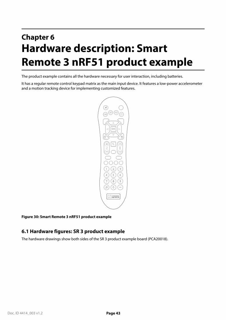
Hardware description: SmartRemote 3 nRF51 product exampleThe product example contains all the hardware necessary for user interaction, including batteries.
It has a regular remote control keypad matrix as the main input device. It features a low-power accelerometerand a motion tracking device for implementing customized features.
Figure 30: Smart Remote 3 nRF51 product example
6.1 Hardware figures: SR 3 product exampleThe hardware drawings show both sides of the SR 3 product example board (PCA20018).

6 Hardware description: Smart Remote 3 nRF51 product example
Doc. ID 4414_003 v1.2 Page 44
Figure 31: SR 3 product example board (PCA20018), front side
Figure 32: SR 3 product example board (PCA20018), back side

6 Hardware description: Smart Remote 3 nRF51 product example
Doc. ID 4414_003 v1.2 Page 45
6.2 Block diagramThe block diagram illustrates Smart Remote 3 DK product example functional architecture.
Battery
Keypad
Codec
nRF51822
Low power accelerometer
Motion tracking device
Analog microphone
Power control
SWD connector
Figure 33: Block diagram
6.3 Design descriptionThe design description contains details about the hardware blocks on the Smart Remote 3 for nRF51 productexample.
6.3.1 I/O usageThe nRF51822-QFAA has 31 generic I/Os available. All I/Os are used in this design and are organized as shownin table below.
Table 5: I/O usage
I/O Label Description
P0.00 DEBUG HALF
P0.01 DEBUG FULL
P0.02 I2C_DATA_2 Two-wire 2 master data
P0.03 I2S LRCLK ADC audio data left and right
P0.04 I2S MCLK Master clock
P0.05 I2C_CLK_2 Two-wire 2 master clock
P0.06 I2S DOUT ADC audio data
P0.07 I2C_CLK Two-wire 1 master clock
P0.08 KEYIN_0 Input from keypad row 0
P0.09 KEYIN_1 Input from keypad row 1

6 Hardware description: Smart Remote 3 nRF51 product example
Doc. ID 4414_003 v1.2 Page 46
I/O Label Description
P0.10 KEYIN_2 Input from keypad row 2
P0.11 KEYIN_3 Input from keypad row 3
P0.12 I2S SCLK Audio data bit clock
P0.13 I2S SCLK Audio data bit clock
P0.14 P0.14 Connected to P0.15
P0.15 P0.15 Connected to P0.14
P0.16 Power switch Control signal power switch
P0.17 KEYIN_4 Input from keypad row 4
P0.18 ICM-20608_INT Motion tracking device interrupt
P0.19 KEYOUT_0 Output to keypad column 0
P0.20 KEYOUT_1 Output to keypad column 1
P0.21 KEYOUT_2 Output to keypad column 2
P0.22 KEYOUT_3 Output to keypad column 3
P0.23 KEYOUT_4 Output to keypad column 4
P0.24 KEYOUT_5 Output to keypad column 5
P0.25 KEYOUT_6 Output to keypad column 6
P0.26 XL1 32.768 kHz crystal
P0.27 XL2 32.768 kHz crystal
P0.28 KEYOUT_7 Output to keypad column 7
P0.29 LIS3DH_INT1 Low-power accelerometerinterrupt 1
P0.30 I2C_DATA Two-wire 1 master data
6.3.2 Keypad matrixThe keypad on the PCA20018 board has 39 buttons.
The keyboard matrix is five rows by eight columns, providing 40 available buttons for firmware. Thirty-nine areused by the keypad with one unused. The matrix is connected directly to the nRF51 device on the board. SeeFigure 34: Keypad matrix on page 47.

6 Hardware description: Smart Remote 3 nRF51 product example
Doc. ID 4414_003 v1.2 Page 47
K1
*
K9
6
K21
TBD
K32
Menu
K40
UP
K17
K2
0
K10
1
K22
TBD
K33
Down
K41
TBD
K18
K3
#
K11
2
K23
V_Down
K34
Exit
K42
TV
K4
7
K12
3
K24
Mute
K35
Left
K43
SAT
K5
8
K13
Red
K25
C_Down
K36
OK
K44
DVD
K6
9
K14
Green
K26
V_Up
K37
Right
K45
AUX
K7
4
K15
Yellow
K27
Back
K38
TBD
K46
Power
K8
5
K16
Blue
K28
C_Up
K47
TBD
K19 K20
K29 K30 K31
K39
P0.1
9
P0. 2
0
P0. 2
1
P0.2
2
P0. 2
3
P0. 2
4
P0. 2
5
P0. 2
8
P0.08
P0.09
P0.10
P0.11
P0.17
KEY
OU
T _0
KE Y
OU
T _1
KEY
OU
T _2
KEY
OU
T _3
KEY
OU
T _4
KEY
OU
T _5
KEY
OU
T _6
KEY
OU
T _7
KEYIN_0
KEYIN_1
KEYIN_2
KEYIN_3
KEYIN_4
Figure 34: Keypad matrix
6.3.3 Low-power accelerometer circuitTo obtain low-power consumption and long battery lifetime, a low-power three-axis accelerometer (U4) hasbeen added to the remote control.
See the schematic below. See also Intelligent power saving on page 24.

6 Hardware description: Smart Remote 3 nRF51 product example
Doc. ID 4414_003 v1.2 Page 48
VD
D14
ADC3 13
GND 12
CS
8SD
O/S
A0
7
INT1 11
RES 10
INT2 9
VDD_IO1
S DA
/SD
I / SD
O6
GND5 SCL/SPC4
NC2
NC3
AD
C2
15A
DC
116 U4
LIS3DH
C3810µF
C37100nF
C43100nF
I2C address: 0x18
I2C_DATA_2
VDD
VDD
VDD
P0.29P0.05
P0.02
I2C_CLK_2LIS3DH_INT1
R24N.C.
R23
0R
Figure 35: Accelerometer circuit
The accelerometer has I2C outputs and can detect motion on three axes. The sensitivity is configurable to ±2g/±4 g/±8 g/±16 g.
6.3.4 Motion tracking deviceFor advanced features, the remote control has a three-axis gyro integrated with a three-axis accelerometer(U3).

6 Hardware description: Smart Remote 3 nRF51 product example
Doc. ID 4414_003 v1.2 Page 49
VDDIO1
SCL//SPC2
SDA/SDI3
SA0/SDO4
CS5
INT 6FSYNC 8
GND 13
REGOUT 14
VDD16
U3ICM-20608
C39100nF
C402.2µF
C4110nF
VCC
I2C_DATA
I2C address: 0x68
C42470nF
R22N.C.
P0.30
SB6
VDD
SB7
VICM
P0.07I2C_CLK
ICM-20608_INTP0.18
I2C
_CL K
_2
I2C
_DA
T A_2
SB11 SB10
SB8
SB9
P 0.0
5
P 0.0
2
VICM
Figure 36: Motion tracking device
The circuit is connected to the MCU by the first I2C. If you want to use the second I2C, there are four solderbridges that you need to change. SB10 and SB11 have to be soldered and SB8 and SB9 have to be cut. Thiscircuit is a ±250° per sec/±500° per sec/±1000° per sec/±2000° per sec selectable three-axis gyro and a ±2 g/±4g/±8 g/±16 g selectable three-axis accelerometer.
6.3.5 Power supplyThe Smart Remote 3 product example is powered by two AA batteries.
The batteries can be alkaline (2 × 1.5 V) or rechargeable NiMH (2 × 1.2 V) batteries. The battery circuit has aprotection diode to avoid reverse current if the board is powered elsewhere. In parallel with the battery thereis a connector (P3) that can be used for supply during development. See Figure 37: Battery schematic on page50.

6 Hardware description: Smart Remote 3 nRF51 product example
Doc. ID 4414_003 v1.2 Page 50
D11PS79SB30.115
VDD
SB5
12
P3
Pin List 1x2
+BatP1AA
+BatN1AA
Figure 37: Battery schematic
There is a power switch on the Smart Remote 3 that is connected to most of the circuits. The nRF chipcontrols the two transistors. See Figure 38: Power on/off switch schematic on page 50. The low-poweraccelerometer is always powered.
VDD
R21
10R
VCC
C35100nF
+C32100µF
1 2
P2Pin List 1x2
GNDC361.0µF
C34100nF
C3322µF
Supply filter/Current measurement
R20
510k
Q1AFDG6321C
Q1BFDG6321C
R19N.C.
P0.16 Power switch
Figure 38: Power on/off switch schematic
6.3.6 CodecThe CODEC is used to digitize and code the signal from the analog microphone.
The Smart Remote 3 uses the ES8218 CODEC from Everest Semiconductor, that utilizes a two-wire interface forsetup commands. The microphone signal is transferred to the nRF chip via I2S interface.

6 Hardware description: Smart Remote 3 nRF51 product example
Doc. ID 4414_003 v1.2 Page 51
R1110R
C29100nF
C28100nF
I2C_DATA
I2S DOUT
I2S SCLK
I2S LRCLK
C30100nF
M1
VMOB6027D
VCC VCC VCC VCC
+C2510µF C31
100nF
+C2610µF
+C2410µF
C211.0µF
R170R
C161.0µF
R102k2 C5
100nF
R6
N.C.
R7
0R
VCCVCC
C27100nF
+C2310µF
R18
33R
R16
33R
R14
33R
R15
1k
FB1600R/0.3A
C151.0µF
+C6100µF
Vmic
C20N.C.
C1910nF
VCC Vmic
MCLK1
DVDD2
LRCK7
DM
IC_S
CL
9
PVDD3
DGND4
NC
10
NC
11
GND6
NC
12
ASD
OU
T8
AG
ND
13
NC
14
NC 15
MIC
BIA
S25
CE
26
NC 16AVDD 17AGND 18ADCVREF 19VMID 20RIN2 21
L IN
222
RIN
123
L IN
124
CC
L K28
CD
AT A
27
ES8218SCLK5
U2ES8218
C22N.C.
SB3
SB4
P0.03
P0.13
P0.04
P0.07P0.30
P0.06
I2S MCLK
I2C_CLK
R12 0R
R13 0R
C17N.C.
C18N.C.
SB1SB2
R50RR8
4k3R94k3
Figure 39: Codec and appurtenant components
6.3.7 Programming interfaceA connector for the ARM SWD interface is included on the product example for easy firmware upgradepurposes.
When this interface is connected to a compatible programmer, firmware upgrades can be made directly onthe board. The interface is found on the 10 pin connector P1, see the figure below.
Figure 40: Location of SWD interface connector P1
Firmware update of Smart Remote 3 on page 54 describes how to connect and perform firmware upgradesand debugging of the product example.
Important: Make sure that pin 1 on the P1 connector on the PCA20018 board is connected to pin 1 ofthe connector on the programmer unit.
Table 6: SWD interface connector pin configuration
Pin Label Description
P1_1 VDD Reference voltage for programmer
P1_2 SWDIO Serial wire debug data
P1_3 GND Ground
P1_4 SWDCLK Serial wire debug clock

6 Hardware description: Smart Remote 3 nRF51 product example
Doc. ID 4414_003 v1.2 Page 52
Pin Label Description
P1_5 GND Ground
P1_6 NC No connection
P1_7 NC No connection
P1_8 NC No connection
P1_9 GND Ground
P1_10 NC No connection
6.3.8 Matching networkThe design is using an integrated balun from Johanson Technology for converting from differential to single-ended signal and transforming the impedance to 50 Ω.
Layout of the matching network, component size, and component values are exactly as given in theapplication example found on Johanson Technology's website. This reference matching network layout is alsoavailable for download from Johanson Technology.
6.3.9 AntennaThe product example has an integrated chip antenna from Johanson Technology.
Go to Johanson Technology for more information on the chip antenna. The antenna is tuned to be resonant at2.44 GHz, and the impedance is matched to the 50 Ω output of the balun with the use of two series inductors(L1 = 3.3 nH, L2 = 1.5 nH) and a shunt capacitor to ground (C4 = 1.2 pF). The antenna in this design is tunedfor this layout only, and with the same plastic casing. If the layout and/or the casing is changed, it is likely theantenna must be retuned. The antenna can be retuned by adjusting the values of L1, L2 and C4. The exactvalues of the components must be determined by measurements with a vector network analyzer.
Figure 41: Matching network and antenna circuit
6.3.10 Schematics, bill of materials, PCB layout files, production filesHardware files for the Smart Remote 3 nRF51 product example are available in a zip package.
The hardware files for the Smart Remote 3 nRF51 product example will be located in the following folder inthe hardware files zip package:
\nRFready Smart Remote 3 for nRF51 series x_x_x\nRF6933 - nRF51 ProductExample x_x_x.

6 Hardware description: Smart Remote 3 nRF51 product example
Doc. ID 4414_003 v1.2 Page 53
In this folder you can find the bill of materials, schematics and PCB layout files in PDF format, Altium Designerfiles, and production files (assembly drawings, gerber files, drill files, pick-and-place files).

Doc. ID 4414_003 v1.2 Page 54
Chapter 7
Firmware update of Smart Remote 3A step-by-step guide for connecting your remote control to a debugger for firmware upgrades on thenRF51822 device is included in this section.
If you are programming the DK add-on, the nRF51 DK has the SEGGER J-Link built in, and can be used throughthe USB cable. If you are programming the product example, the nRF51 DK can be used as the debugger.
7.1 Connect the product example to the nRF51 DKThe programming and debugging interface of the nRF51822 is accessed through a 10-pin connector (P1) onthe product example.
To be able to program and debug, the product example needs to be connected to a SEGGER J-Link device. Inthis user guide we will use the nRF51 Development Kit as reference. Make sure that pin 1 on the Debug Outconnector on the nRF51 DK is connected to pin 1 on the P1 connector on the PCA20018 board. Figure 42: Pin1 position on page 54 shows the position of pin 1 on the Debug out connector.
Figure 42: Pin 1 position
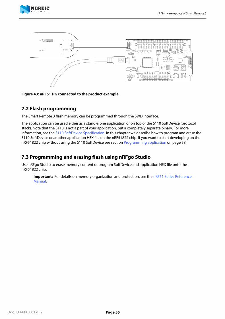
To connect the product example to the nRF51 DK, use a 10 pin flat cable. Connect the cable to the productexample so there will be a 1-1 mapping of the pins. Figure 43: nRF51 DK connected to the product example onpage 55 shows what the connection should look like.
7 Firmware update of Smart Remote 3
Doc. ID 4414_003 v1.2 Page 55
Figure 43: nRF51 DK connected to the product example
7.2 Flash programmingThe Smart Remote 3 flash memory can be programmed through the SWD interface.
The application can be used either as a stand-alone application or on top of the S110 SoftDevice (protocolstack). Note that the S110 is not a part of your application, but a completely separate binary. For moreinformation, see the S110 SoftDevice Specification. In this chapter we describe how to program and erase theS110 SoftDevice or another application HEX file on the nRF51822 chip. If you want to start developing on thenRF51822 chip without using the S110 SoftDevice see section Programming application on page 58.
7.3 Programming and erasing flash using nRFgo StudioUse nRFgo Studio to erase memory content or program SoftDevice and application HEX file onto thenRF51822 chip.
Important: For details on memory organization and protection, see the nRF51 Series ReferenceManual.

7 Firmware update of Smart Remote 3
Doc. ID 4414_003 v1.2 Page 56
Figure 44: nRFgo Studio dashboard
7.4 Selecting a board to programThis shows the steps you need to do to select the board to program.
1. Open nRFgo Studio.2. In the Device Manager pane, select nRF51 development boards.3. Select the Segger ID matching the nRF51 DK connected to the product example.
7.5 Chip and memory informationWhen you select a board, nRFgo Studio identifies the nRF chip and how its memory is organized.
Table 7: Chip and memory information displayed in nRFgo Studio
Chip and memory information Description
nRF chip identification Identifies the chip by name and code variant (forexample, nRF51822 QFAAA0).
If the debugger is not connected to the chip, orthe debugger has a problem communicating withthe chip, it will show the following message “Nodevice detected. Ensure that you have the SEGGERconnected correctly to the board and that the boardis powered and configured for debugging.”
7 Firmware update of Smart Remote 3
Doc. ID 4414_003 v1.2 Page 57
Chip and memory information Description
Code memory Shows how the code memory is organized in oneor two regions (Region 0 and 1) and the size of eachregion.
For devices containing a SoftDevice, the codememory is divided in two regions, with theSoftDevice in Region 0. The tool shows you howmuch memory is used by the SoftDevice and howmuch is left for the application.
Memory readback protection Shows how readback protection is set.
The two possible options are readback protectionon Region 0 or readback protection of the wholecode memory. If there is only one region the option isreadback protection on (All) or off.
SoftDevice identification nRFgo Studio tries to identify the firmware locatedin the chip at Region 0. For the firmware that itrecognizes it displays the ID (in clear text) for theunrecognized firmware it displays the FWID number.
7.6 Erase allThe Erase all function will clear everything in the flash memory.
Use Erase all in the following situations:
• You have a chip that is programmed with a SoftDevice but you want to remove it and have a blank chip.• You have programmed an application on a clean chip using nRFgo Studio with the option Lock entire chip
from readback.
To use the Erase all function, follow the steps in section Selecting a board to program on page 56. Thenclick Erase all.
7.7 Programming SoftDeviceThis function lets you program the SoftDevice onto the chip.
Before you start, perform the steps in Selecting a board to program on page 56.
Program the SoftDevice onto the chip in the Program SoftDevice tab.
7 Firmware update of Smart Remote 3
Doc. ID 4414_003 v1.2 Page 58
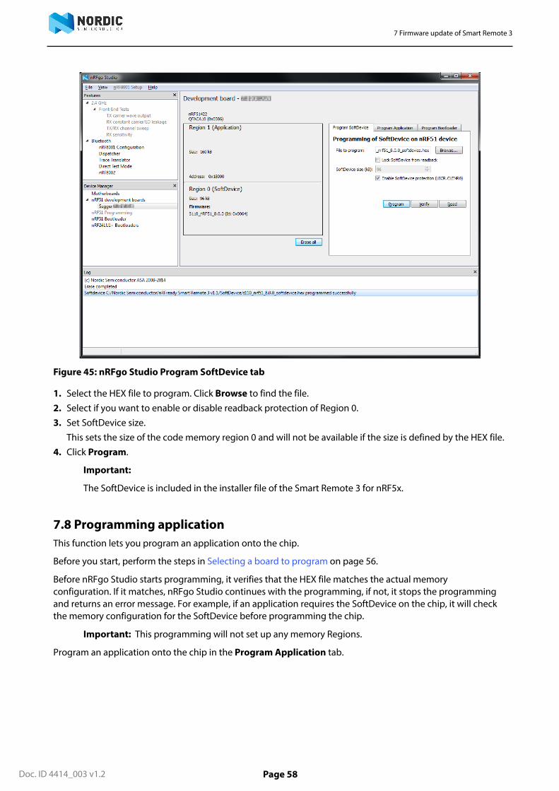
Figure 45: nRFgo Studio Program SoftDevice tab
1. Select the HEX file to program. Click Browse to find the file.2. Select if you want to enable or disable readback protection of Region 0.3. Set SoftDevice size.
This sets the size of the code memory region 0 and will not be available if the size is defined by the HEX file.4. Click Program.
Important:
The SoftDevice is included in the installer file of the Smart Remote 3 for nRF5x.
7.8 Programming applicationThis function lets you program an application onto the chip.
Before you start, perform the steps in Selecting a board to program on page 56.
Before nRFgo Studio starts programming, it verifies that the HEX file matches the actual memoryconfiguration. If it matches, nRFgo Studio continues with the programming, if not, it stops the programmingand returns an error message. For example, if an application requires the SoftDevice on the chip, it will checkthe memory configuration for the SoftDevice before programming the chip.
Important: This programming will not set up any memory Regions.
Program an application onto the chip in the Program Application tab.

7 Firmware update of Smart Remote 3
Doc. ID 4414_003 v1.2 Page 59
Figure 46: nRFgo Studio Program Application tab
1. Select the HEX file to program. Click Browse to find the file.2. Select if you want enable or disable readback protection of the entire chip.
If you enable readback protection, you will have to do an Erase all to reprogram the chip again.
A chip that is programmed with Lock entire chip from readback enabled will not work with adevelopment toolchain. To make it work you must perform Erase all. Lock entire chip from readback canbe used to prevent an accidental overwrite of chip content.
3. Click Program.

Doc. ID 4414_003 v1.2 Page 60
Legal notices
By using this documentation you agree to our terms and conditions of use. Nordic Semiconductor maychange these terms and conditions at any time without notice.
Liability disclaimer
Nordic Semiconductor ASA reserves the right to make changes without further notice to the product toimprove reliability, function or design. Nordic Semiconductor ASA does not assume any liability arising out ofthe application or use of any product or circuits described herein.
All information contained in this document represents information on the product at the time of publication.Nordic Semiconductor ASA reserves the right to make corrections, enhancements, and other changes tothis document without notice. While Nordic Semiconductor ASA has used reasonable care in preparingthe information included in this document, it may contain technical or other inaccuracies, omissions andtypographical errors. Nordic Semiconductor ASA assumes no liability whatsoever for any damages incurred byyou resulting from errors in or omissions from the information included herein.
Life support applications
Nordic Semiconductor products are not designed for use in life support appliances, devices, or systems wheremalfunction of these products can reasonably be expected to result in personal injury.
Nordic Semiconductor ASA customers using or selling these products for use in such applications do so attheir own risk and agree to fully indemnify Nordic Semiconductor ASA for any damages resulting from suchimproper use or sale.
RoHS and REACH statement
Nordic Semiconductor products meet the requirements of Directive 2002/95/EC of the European Parliamentand of the Council on the Restriction of Hazardous Substances (RoHS) and the requirements of the REACHregulation (EC 1907/2006) on Registration, Evaluation, Authorization and Restriction of Chemicals.
The SVHC (Substances of Very High Concern) candidate list is continually being updated. Complete hazardoussubstance reports, material composition reports and latest version of Nordic's REACH statement can be foundon our website www.nordicsemi.com.
Trademarks
All trademarks, service marks, trade names, product names and logos appearing in this documentation are theproperty of their respective owners.
Copyright notice
© 2017 Nordic Semiconductor ASA. All rights are reserved. Reproduction in whole or in part is prohibitedwithout the prior written permission of the copyright holder.

All rights reserved.Reproduction in whole or in part is prohibited without the prior written permission of the copyright holder.


![ZigBee PRO Green Power feature. GP Basic functionality set ...infocenter.nordicsemi.com/pdf/15-02016-010-GP_Errata_for_GP_Basic_PICS... · [R6] ZigBee document 064113r08: ZigBee Cluster](https://img.pdfslide.us/doc/110x75/5e1ac48ce0388672b742a31c/zigbee-pro-green-power-feature-gp-basic-functionality-set-r6-zigbee-document.jpg)