Embed Size (px)
Citation preview

1
REG-DA
REG-DA operating manual
Operating ManualREG-DA Relay for Voltage Control & Transformer Monitoring
Issue 18.10.07/03a
Issue GBVersion 10.2007
Software Version

2
REG-DA
REG-DA operating manual
REG-DA Relay for Voltage Control & Transformer Monitoring
Operating ManualIssue 18.10.07
Copyright 2007 by A. Eberle GmbH & Co. KG.. All rights reserved.
Published by:
A. Eberle GmbH & Co. KG
Frankenstraße 160
D-90461 Nuremberg, Germany
Tel.: +49 (0) 911 / 62 81 08 - 0
Fax No.: +49 (0)-911 / 62 81 08 - 96
e-mail: [email protected]
Internet: www.a-eberle.de, www.regsys.de
The company A. Eberle GmbH & Co. KG cannot be held liable for any damages or losses resulting from printing errors or changes in this operating manual.
Furthermore, A. Eberle GmbH & Co. KG does not assume responsibility for any damages and losses resulting from defective devices or from devices altered by the user.

3
REG-DA
REG-DA operating manual
Table of Contents
1 Warnings and Information . . . . . . . . . . . . . . . . . . . . . . . . . . . . . . . . . . . . . . . . . . . 9
2 Scope of Delivery. . . . . . . . . . . . . . . . . . . . . . . . . . . . . . . . . . . . . . . . . . . . . . . . . 11
3 Technical Data. . . . . . . . . . . . . . . . . . . . . . . . . . . . . . . . . . . . . . . . . . . . . . . . . . . 123.1 Basic equipment . . . . . . . . . . . . . . . . . . . . . . . . . . . . . . . . . . . . . . . . . . . . . . . . . . . . . . . . . 12
3.2 Connection diagram . . . . . . . . . . . . . . . . . . . . . . . . . . . . . . . . . . . . . . . . . . . . . . . . . . . . . . . 14
3.3 Overview of features. . . . . . . . . . . . . . . . . . . . . . . . . . . . . . . . . . . . . . . . . . . . . . . . . . . . . . . 15
3.4 Block diagrams . . . . . . . . . . . . . . . . . . . . . . . . . . . . . . . . . . . . . . . . . . . . . . . . . . . . . . . . . . 213.4.1 Block diagram for features D0/D1/D4 . . . . . . . . . . . . . . . . . . . . . . . . . . . . . . . . . . . . . . . . . . . . . . . . . . . 213.4.2 Block diagram for features D2/D3. . . . . . . . . . . . . . . . . . . . . . . . . . . . . . . . . . . . . . . . . . . . . . . . . . . . . . 22
3.5 Pin Assignment . . . . . . . . . . . . . . . . . . . . . . . . . . . . . . . . . . . . . . . . . . . . . . . . . . . . . . . . . . 233.5.1 Pin assignment level I . . . . . . . . . . . . . . . . . . . . . . . . . . . . . . . . . . . . . . . . . . . . . . . . . . . . . . . . . . . . . . 293.5.2 Pin assignment level II . . . . . . . . . . . . . . . . . . . . . . . . . . . . . . . . . . . . . . . . . . . . . . . . . . . . . . . . . . . . . . 353.5.3 Pin assignment level III. . . . . . . . . . . . . . . . . . . . . . . . . . . . . . . . . . . . . . . . . . . . . . . . . . . . . . . . . . . . . . 41
3.6 Types of REG-DA Relay for Voltage Control & Transformer Monitoring . . . . . . . . . . . . . . . . . . . 443.6.1 Wall-mounting version . . . . . . . . . . . . . . . . . . . . . . . . . . . . . . . . . . . . . . . . . . . . . . . . . . . . . . . . . . . . . . 443.6.2 Panel-mounting version . . . . . . . . . . . . . . . . . . . . . . . . . . . . . . . . . . . . . . . . . . . . . . . . . . . . . . . . . . . . . 453.6.3 Mounting on Standard Mounting Rails. . . . . . . . . . . . . . . . . . . . . . . . . . . . . . . . . . . . . . . . . . . . . . . . . . . 46
4 Operation. . . . . . . . . . . . . . . . . . . . . . . . . . . . . . . . . . . . . . . . . . . . . . . . . . . . . . . 474.1 Display and control elements . . . . . . . . . . . . . . . . . . . . . . . . . . . . . . . . . . . . . . . . . . . . . . . . 474.1.1 Display . . . . . . . . . . . . . . . . . . . . . . . . . . . . . . . . . . . . . . . . . . . . . . . . . . . . . . . . . . . . . . . . . . . . . . . . . 50
4.2 Operating principle . . . . . . . . . . . . . . . . . . . . . . . . . . . . . . . . . . . . . . . . . . . . . . . . . . . . . . . . 51
4.3 Selecting the display mode . . . . . . . . . . . . . . . . . . . . . . . . . . . . . . . . . . . . . . . . . . . . . . . . . . 52
4.4 Lamp check. . . . . . . . . . . . . . . . . . . . . . . . . . . . . . . . . . . . . . . . . . . . . . . . . . . . . . . . . . . . . 58
4.5 Resetting fault signals . . . . . . . . . . . . . . . . . . . . . . . . . . . . . . . . . . . . . . . . . . . . . . . . . . . . . 58
4.6 Operating the recorder . . . . . . . . . . . . . . . . . . . . . . . . . . . . . . . . . . . . . . . . . . . . . . . . . . . . . 58

4
REG-DA
REG-DA operating manual
5 Commissioning. . . . . . . . . . . . . . . . . . . . . . . . . . . . . . . . . . . .635.1 Regulator mode . . . . . . . . . . . . . . . . . . . . . . . . . . . . . . . . . . . . . . . . . . . . . . . . . . . . . . . . . . 65
5.2 Measurement transducer mode. . . . . . . . . . . . . . . . . . . . . . . . . . . . . . . . . . . . . . . . . . . . . . . 66
5.3 Recorder mode. . . . . . . . . . . . . . . . . . . . . . . . . . . . . . . . . . . . . . . . . . . . . . . . . . . . . . . . . . . 67
5.4 Statistics mode. . . . . . . . . . . . . . . . . . . . . . . . . . . . . . . . . . . . . . . . . . . . . . . . . . . . . . . . . . . 68
5.5 ParaGramer mode . . . . . . . . . . . . . . . . . . . . . . . . . . . . . . . . . . . . . . . . . . . . . . . . . . . . . . . . 69
5.6 Choosing the language . . . . . . . . . . . . . . . . . . . . . . . . . . . . . . . . . . . . . . . . . . . . . . . . . . . . . 70
5.7 Setpoint value . . . . . . . . . . . . . . . . . . . . . . . . . . . . . . . . . . . . . . . . . . . . . . . . . . . . . . . . . . . 70
5.8 Permissible regulative deviation Xwz . . . . . . . . . . . . . . . . . . . . . . . . . . . . . . . . . . . . . . . . . . . 71
5.9 Time behaviour. . . . . . . . . . . . . . . . . . . . . . . . . . . . . . . . . . . . . . . . . . . . . . . . . . . . . . . . . . . 72
5.10 Backward high-speed switching . . . . . . . . . . . . . . . . . . . . . . . . . . . . . . . . . . . . . . . . . . . . . . 75
5.11 Tap-changer running time. . . . . . . . . . . . . . . . . . . . . . . . . . . . . . . . . . . . . . . . . . . . . . . . . . . 77
5.12 Knx transformer mounting ratios and transformer connection . . . . . . . . . . . . . . . . . . . . . . . . . 79
5.13 Setting the nominal current . . . . . . . . . . . . . . . . . . . . . . . . . . . . . . . . . . . . . . . . . . . . . . . . . . 80
5.14 Inhibit low limit . . . . . . . . . . . . . . . . . . . . . . . . . . . . . . . . . . . . . . . . . . . . . . . . . . . . . . . . . . . 82
5.15 Trigger. . . . . . . . . . . . . . . . . . . . . . . . . . . . . . . . . . . . . . . . . . . . . . . . . . . . . . . . . . . . . . . . . 84
5.16 Short description of individual limit values, setpoint values and permissible regulative deviation. 855.16.1 Description of the individual settings. . . . . . . . . . . . . . . . . . . . . . . . . . . . . . . . . . . . . . . . . . . . . . . . . . . . .85
6 Basic Settings . . . . . . . . . . . . . . . . . . . . . . . . . . . . . . . . . . . . . . . . . . . . . . . . . . . 916.1 General . . . . . . . . . . . . . . . . . . . . . . . . . . . . . . . . . . . . . . . . . . . . . . . . . . . . . . . . . . . . . . . . 916.1.1 Station ID . . . . . . . . . . . . . . . . . . . . . . . . . . . . . . . . . . . . . . . . . . . . . . . . . . . . . . . . . . . . . . . . . . . . . . . .916.1.2 Station name. . . . . . . . . . . . . . . . . . . . . . . . . . . . . . . . . . . . . . . . . . . . . . . . . . . . . . . . . . . . . . . . . . . . . .926.1.3 Setting the time/date . . . . . . . . . . . . . . . . . . . . . . . . . . . . . . . . . . . . . . . . . . . . . . . . . . . . . . . . . . . . . . . .936.1.4 LCD contrast (display) . . . . . . . . . . . . . . . . . . . . . . . . . . . . . . . . . . . . . . . . . . . . . . . . . . . . . . . . . . . . . . .946.1.5 Password . . . . . . . . . . . . . . . . . . . . . . . . . . . . . . . . . . . . . . . . . . . . . . . . . . . . . . . . . . . . . . . . . . . . . . . .946.1.6 Deleting recorder data (resetting the measured value memory). . . . . . . . . . . . . . . . . . . . . . . . . . . . . . . . . .956.1.7 Deleting tap-change sums (resetting the tap-counter to zero). . . . . . . . . . . . . . . . . . . . . . . . . . . . . . . . . . .966.1.8 Actual value correction of the measuring voltage UE. . . . . . . . . . . . . . . . . . . . . . . . . . . . . . . . . . . . . . . . . .966.1.9 Actual value correction of the measuring current IE . . . . . . . . . . . . . . . . . . . . . . . . . . . . . . . . . . . . . . . . . .96
6.2 RS-232 interfaces . . . . . . . . . . . . . . . . . . . . . . . . . . . . . . . . . . . . . . . . . . . . . . . . . . . . . . . . 976.2.1 COM 1 . . . . . . . . . . . . . . . . . . . . . . . . . . . . . . . . . . . . . . . . . . . . . . . . . . . . . . . . . . . . . . . . . . . . . . . . . .976.2.2 COM 2 . . . . . . . . . . . . . . . . . . . . . . . . . . . . . . . . . . . . . . . . . . . . . . . . . . . . . . . . . . . . . . . . . . . . . . . . . .99
6.3 E-LAN (Energy-Local Area Network) . . . . . . . . . . . . . . . . . . . . . . . . . . . . . . . . . . . . . . . . . . . 101
6.4 PAN-D voltage monitoring unit. . . . . . . . . . . . . . . . . . . . . . . . . . . . . . . . . . . . . . . . . . . . . . . 104
6.5 Status (current ID data of the REG-DA Relay for Voltage Control & Transformer Monitoring). . . 104

5
REG-DA
REG-DA operating manual
7 Parameterisation of the REG-DA Relay for Voltage Control & Transformer Monitoring . . . . . . . . . . . . . . . . . . . . . . . . . . . . . . . . . . . . . . . . . . . . . . . . . . . . . 108
7.1 Permissible regulative deviation . . . . . . . . . . . . . . . . . . . . . . . . . . . . . . . . . . . . . . . . . . . . . 109
7.2 Time behaviour (regulation behaviour) . . . . . . . . . . . . . . . . . . . . . . . . . . . . . . . . . . . . . . . . . 1097.2.1 Time factor . . . . . . . . . . . . . . . . . . . . . . . . . . . . . . . . . . . . . . . . . . . . . . . . . . . . . . . . . . . . . . . . . . . . . 1097.2.2 Time program . . . . . . . . . . . . . . . . . . . . . . . . . . . . . . . . . . . . . . . . . . . . . . . . . . . . . . . . . . . . . . . . . . . 1107.2.3 Trend memory. . . . . . . . . . . . . . . . . . . . . . . . . . . . . . . . . . . . . . . . . . . . . . . . . . . . . . . . . . . . . . . . . . . 110
7.3 Setpoints . . . . . . . . . . . . . . . . . . . . . . . . . . . . . . . . . . . . . . . . . . . . . . . . . . . . . . . . . . . . . . 1117.3.1 1st setpoint value . . . . . . . . . . . . . . . . . . . . . . . . . . . . . . . . . . . . . . . . . . . . . . . . . . . . . . . . . . . . . . . . 1117.3.2 Further setpoint values. . . . . . . . . . . . . . . . . . . . . . . . . . . . . . . . . . . . . . . . . . . . . . . . . . . . . . . . . . . . . 112
7.4 Programs (parameters for parallel regulation of transformers and for the compensation of the voltage drop on the line) . . . . . . . . . . . . . . . . . . . . . . . . . . . . . . . . . . . . . . . . . . . . . . . . . . . 113
7.4.1 Selection of the parallel programs (regulation programs) . . . . . . . . . . . . . . . . . . . . . . . . . . . . . . . . . . . . 1137.4.2 Parameters for the parallel program . . . . . . . . . . . . . . . . . . . . . . . . . . . . . . . . . . . . . . . . . . . . . . . . . . . 1147.4.3 Current influence (line-drop compensation) . . . . . . . . . . . . . . . . . . . . . . . . . . . . . . . . . . . . . . . . . . . . . . 1167.4.4 LDC parameter (line drop compensation). . . . . . . . . . . . . . . . . . . . . . . . . . . . . . . . . . . . . . . . . . . . . . . . 116
7.5 Gradient (U/I characteristic). . . . . . . . . . . . . . . . . . . . . . . . . . . . . . . . . . . . . . . . . . . . . . . . . 117
7.6 Limitation (U/I characteristic). . . . . . . . . . . . . . . . . . . . . . . . . . . . . . . . . . . . . . . . . . . . . . . . 117
7.7 < U Undervoltage . . . . . . . . . . . . . . . . . . . . . . . . . . . . . . . . . . . . . . . . . . . . . . . . . . . . . . . . 117
7.8 > U Overvoltage. . . . . . . . . . . . . . . . . . . . . . . . . . . . . . . . . . . . . . . . . . . . . . . . . . . . . . . . . 118
7.9 > I, < Limit (upper and lower current limits). . . . . . . . . . . . . . . . . . . . . . . . . . . . . . . . . . . . . 118
7.10 Trigger inhibit high (highest limit value of the voltage). . . . . . . . . . . . . . . . . . . . . . . . . . . . . . 119
7.11 High-speed switching during undervoltage/overvoltage. . . . . . . . . . . . . . . . . . . . . . . . . . . . . 1207.11.1 High-speed switching when undervoltage occurs (RAISE) . . . . . . . . . . . . . . . . . . . . . . . . . . . . . . . . . . . . 1207.11.2 High-speed switching when overvoltage occurs (LOWER) . . . . . . . . . . . . . . . . . . . . . . . . . . . . . . . . . . . . 120
7.12 REG-DA inhibit low when undervoltage occurs . . . . . . . . . . . . . . . . . . . . . . . . . . . . . . . . . . . 121
7.13 Time delays (limit signals) . . . . . . . . . . . . . . . . . . . . . . . . . . . . . . . . . . . . . . . . . . . . . . . . . . 1217.13.1 Time delay > U . . . . . . . . . . . . . . . . . . . . . . . . . . . . . . . . . . . . . . . . . . . . . . . . . . . . . . . . . . . . . . . . . . 1217.13.2 Time delay < U . . . . . . . . . . . . . . . . . . . . . . . . . . . . . . . . . . . . . . . . . . . . . . . . . . . . . . . . . . . . . . . . . . 1227.13.3 Time delay > I, < I limit value. . . . . . . . . . . . . . . . . . . . . . . . . . . . . . . . . . . . . . . . . . . . . . . . . . . . . . . . 1227.13.4 Time delay trigger . . . . . . . . . . . . . . . . . . . . . . . . . . . . . . . . . . . . . . . . . . . . . . . . . . . . . . . . . . . . . . . . 1227.13.5 Time delay forward high-speed switching . . . . . . . . . . . . . . . . . . . . . . . . . . . . . . . . . . . . . . . . . . . . . . . 1237.13.6 Time delay backward high-speed switching . . . . . . . . . . . . . . . . . . . . . . . . . . . . . . . . . . . . . . . . . . . . . 1237.13.7 Time delay inhibit low . . . . . . . . . . . . . . . . . . . . . . . . . . . . . . . . . . . . . . . . . . . . . . . . . . . . . . . . . . . . . 124

6
REG-DA
REG-DA operating manual
7.14 Add-Ons (Relay for Voltage Control & Transformer Monitoring behaviour) . . . . . . . . . . . . . . . . 1247.14.1 Overview of the Add-Ons menus numbers 1 to 6. . . . . . . . . . . . . . . . . . . . . . . . . . . . . . . . . . . . . . . . . . .1247.14.2 Maximum time TC in operation (motor-drive-in operation-time) . . . . . . . . . . . . . . . . . . . . . . . . . . . . . . . .1267.14.3 Manual/Automatic . . . . . . . . . . . . . . . . . . . . . . . . . . . . . . . . . . . . . . . . . . . . . . . . . . . . . . . . . . . . . . . . .1277.14.4 Tap-changing . . . . . . . . . . . . . . . . . . . . . . . . . . . . . . . . . . . . . . . . . . . . . . . . . . . . . . . . . . . . . . . . . . . .1287.14.5 Self-conduction of the operating mode . . . . . . . . . . . . . . . . . . . . . . . . . . . . . . . . . . . . . . . . . . . . . . . . . .1297.14.6 Current display (of the transformer) . . . . . . . . . . . . . . . . . . . . . . . . . . . . . . . . . . . . . . . . . . . . . . . . . . . .1297.14.7 LCD saver (display) . . . . . . . . . . . . . . . . . . . . . . . . . . . . . . . . . . . . . . . . . . . . . . . . . . . . . . . . . . . . . . . .1307.14.8 Regulator mode: large display . . . . . . . . . . . . . . . . . . . . . . . . . . . . . . . . . . . . . . . . . . . . . . . . . . . . . . . .1307.14.9 Language selection . . . . . . . . . . . . . . . . . . . . . . . . . . . . . . . . . . . . . . . . . . . . . . . . . . . . . . . . . . . . . . . .1317.14.10 Parallel Program Activation . . . . . . . . . . . . . . . . . . . . . . . . . . . . . . . . . . . . . . . . . . . . . . . . . . . . . . . . . .1327.14.11 Up/down relay on time. . . . . . . . . . . . . . . . . . . . . . . . . . . . . . . . . . . . . . . . . . . . . . . . . . . . . . . . . . . . . .1327.14.12 AUTO(MATIC) LOCK in the event of an E-LAN error . . . . . . . . . . . . . . . . . . . . . . . . . . . . . . . . . . . . . . . . .1337.14.13 Setpoint adjustment. . . . . . . . . . . . . . . . . . . . . . . . . . . . . . . . . . . . . . . . . . . . . . . . . . . . . . . . . . . . . . . .1337.14.14 Creeping net breakdown . . . . . . . . . . . . . . . . . . . . . . . . . . . . . . . . . . . . . . . . . . . . . . . . . . . . . . . . . . . .1347.14.15 Limit base (reference value) . . . . . . . . . . . . . . . . . . . . . . . . . . . . . . . . . . . . . . . . . . . . . . . . . . . . . . . . . .1357.14.16 Setting the Relay for Voltage Control & Transformer Monitoring to inhibit low if <I or >I . . . . . . . . . . . . . . .1367.14.17 Maximum tap difference (monitoring) . . . . . . . . . . . . . . . . . . . . . . . . . . . . . . . . . . . . . . . . . . . . . . . . . . .1367.14.18 ParaGramer activation . . . . . . . . . . . . . . . . . . . . . . . . . . . . . . . . . . . . . . . . . . . . . . . . . . . . . . . . . . . . . .137
7.15 Transformer configuration . . . . . . . . . . . . . . . . . . . . . . . . . . . . . . . . . . . . . . . . . . . . . . . . . . 1387.15.1 Transformer mounting voltage (measurement voltage) . . . . . . . . . . . . . . . . . . . . . . . . . . . . . . . . . . . . . . .1387.15.2 Transformer mounting ratio for the voltage . . . . . . . . . . . . . . . . . . . . . . . . . . . . . . . . . . . . . . . . . . . . . . .1407.15.3 Transformer mounting current (conductor connection) . . . . . . . . . . . . . . . . . . . . . . . . . . . . . . . . . . . . . . .1407.15.4 Transformer mounting current (conversion 1 A / 5 A). . . . . . . . . . . . . . . . . . . . . . . . . . . . . . . . . . . . . . . .1407.15.5 Transformer mounting ratio for the current . . . . . . . . . . . . . . . . . . . . . . . . . . . . . . . . . . . . . . . . . . . . . . .141
7.16 Input assignments (binary inputs). . . . . . . . . . . . . . . . . . . . . . . . . . . . . . . . . . . . . . . . . . . . . 142
7.17 Relay assignments . . . . . . . . . . . . . . . . . . . . . . . . . . . . . . . . . . . . . . . . . . . . . . . . . . . . . . . 143
7.18 LED assignments . . . . . . . . . . . . . . . . . . . . . . . . . . . . . . . . . . . . . . . . . . . . . . . . . . . . . . . . 145
8 Measurement Value Simulation . . . . . . . . . . . . . . . . . . . . . . . . . . . . . . . . . . . . 1468.1 Setting the simulated voltage. . . . . . . . . . . . . . . . . . . . . . . . . . . . . . . . . . . . . . . . . . . . . . . . 148
8.2 Setting the simulated current. . . . . . . . . . . . . . . . . . . . . . . . . . . . . . . . . . . . . . . . . . . . . . . . 148
8.3 Setting the simulated phase angle . . . . . . . . . . . . . . . . . . . . . . . . . . . . . . . . . . . . . . . . . . . . 148
8.4 Setting the simulated tap-change . . . . . . . . . . . . . . . . . . . . . . . . . . . . . . . . . . . . . . . . . . . . 149
9 Parallel Operation of Transformers with REG-DA . . . . . . . . . . . . . . . . . . . . . . . 1509.1 Circuit diagram (schematic) . . . . . . . . . . . . . . . . . . . . . . . . . . . . . . . . . . . . . . . . . . . . . . . . . 152
9.2 Programs for parallel operation and their prerequisites . . . . . . . . . . . . . . . . . . . . . . . . . . . . . 1549.2.1 Preparation . . . . . . . . . . . . . . . . . . . . . . . . . . . . . . . . . . . . . . . . . . . . . . . . . . . . . . . . . . . . . . . . . . . . . .1549.2.2 Preparing manual activation . . . . . . . . . . . . . . . . . . . . . . . . . . . . . . . . . . . . . . . . . . . . . . . . . . . . . . . . . .1569.2.3 Preparing automatic activation . . . . . . . . . . . . . . . . . . . . . . . . . . . . . . . . . . . . . . . . . . . . . . . . . . . . . . . .163
9.3 Parallel operation using the “Master-Slave-Independent (MSI)” procedure . . . . . . . . . . . . . . . 1739.3.1 Trouble-shooting . . . . . . . . . . . . . . . . . . . . . . . . . . . . . . . . . . . . . . . . . . . . . . . . . . . . . . . . . . . . . . . . . .184

7
REG-DA
REG-DA operating manual
10 Resistance Measuring Equipment for Tap-Changers with Resistance-Coded Tap-Change Signalling . . . . . . . . . . . . . . . . . . . . . . . . . . . . . . . . . . . . . . . . . . . . . . . 187
10.1 Error detection . . . . . . . . . . . . . . . . . . . . . . . . . . . . . . . . . . . . . . . . . . . . . . . . . . . . . . . . . . 188
10.2 Level detection. . . . . . . . . . . . . . . . . . . . . . . . . . . . . . . . . . . . . . . . . . . . . . . . . . . . . . . . . . 188
10.3 Pin assignment . . . . . . . . . . . . . . . . . . . . . . . . . . . . . . . . . . . . . . . . . . . . . . . . . . . . . . . . . 189
10.4 Connection options. . . . . . . . . . . . . . . . . . . . . . . . . . . . . . . . . . . . . . . . . . . . . . . . . . . . . . . 190
10.5 Setting of the DIP switch S1 and S2 . . . . . . . . . . . . . . . . . . . . . . . . . . . . . . . . . . . . . . . . . . 19110.5.1 Location of the switch on the circuit board: level 1. . . . . . . . . . . . . . . . . . . . . . . . . . . . . . . . . . . . . . . . . 191
11 mA-Inputs, mA-Outputs. . . . . . . . . . . . . . . . . . . . . . . . . . . . . . . . . . . . . . . . . . . 19211.1 Analogue inputs . . . . . . . . . . . . . . . . . . . . . . . . . . . . . . . . . . . . . . . . . . . . . . . . . . . . . . . . . 193
11.2 Analogue outputs . . . . . . . . . . . . . . . . . . . . . . . . . . . . . . . . . . . . . . . . . . . . . . . . . . . . . . . . 203
12 Updating the Operating Software . . . . . . . . . . . . . . . . . . . . . . . . . . . . . . . . . . . 21412.1 Preparing the PC . . . . . . . . . . . . . . . . . . . . . . . . . . . . . . . . . . . . . . . . . . . . . . . . . . . . . . . . 21512.1.1 Windows NT/2000/XP operating system . . . . . . . . . . . . . . . . . . . . . . . . . . . . . . . . . . . . . . . . . . . . . . . . 215
12.2 Starting the bootstrap loader. . . . . . . . . . . . . . . . . . . . . . . . . . . . . . . . . . . . . . . . . . . . . . . . 215
13 Maintenance and Current Consumption . . . . . . . . . . . . . . . . . . . . . . . . . . . . . . 22013.1 Cleaning information . . . . . . . . . . . . . . . . . . . . . . . . . . . . . . . . . . . . . . . . . . . . . . . . . . . . . 220
13.2 Changíng fuses . . . . . . . . . . . . . . . . . . . . . . . . . . . . . . . . . . . . . . . . . . . . . . . . . . . . . . . . . 221
13.3 Changing the battery . . . . . . . . . . . . . . . . . . . . . . . . . . . . . . . . . . . . . . . . . . . . . . . . . . . . . 221
13.4 REG-DA Current Consumption. . . . . . . . . . . . . . . . . . . . . . . . . . . . . . . . . . . . . . . . . . . . . . . 223
13.5 Replacing the device . . . . . . . . . . . . . . . . . . . . . . . . . . . . . . . . . . . . . . . . . . . . . . . . . . . . . 224
14 Storage Information. . . . . . . . . . . . . . . . . . . . . . . . . . . . . . . . . . . . . . . . . . . . . . 225
15 Background Information . . . . . . . . . . . . . . . . . . . . . . . . . . . . . . . . . . . . . . . . . . 22615.1 Regulator mode . . . . . . . . . . . . . . . . . . . . . . . . . . . . . . . . . . . . . . . . . . . . . . . . . . . . . . . . . 226
15.2 Command variable W . . . . . . . . . . . . . . . . . . . . . . . . . . . . . . . . . . . . . . . . . . . . . . . . . . . . . 22715.2.1 Fixed command variable . . . . . . . . . . . . . . . . . . . . . . . . . . . . . . . . . . . . . . . . . . . . . . . . . . . . . . . . . . . 22715.2.2 Variable command variable . . . . . . . . . . . . . . . . . . . . . . . . . . . . . . . . . . . . . . . . . . . . . . . . . . . . . . . . . 22815.2.3 Current-dependent setpoint value increment . . . . . . . . . . . . . . . . . . . . . . . . . . . . . . . . . . . . . . . . . . . . . 231
15.3 Summary and Examples for Current Influencing . . . . . . . . . . . . . . . . . . . . . . . . . . . . . . . . . . 235
15.4 Regulative deviations . . . . . . . . . . . . . . . . . . . . . . . . . . . . . . . . . . . . . . . . . . . . . . . . . . . . . 23815.4.1 Regulative deviation Xw . . . . . . . . . . . . . . . . . . . . . . . . . . . . . . . . . . . . . . . . . . . . . . . . . . . . . . . . . . . . 23815.4.2 Permissible regulative deviation Xwz . . . . . . . . . . . . . . . . . . . . . . . . . . . . . . . . . . . . . . . . . . . . . . . . . . . 23815.4.3 Displaying the regulative deviation Xw. . . . . . . . . . . . . . . . . . . . . . . . . . . . . . . . . . . . . . . . . . . . . . . . . . 23915.4.4 Setting the permissible regulative deviation Xwz . . . . . . . . . . . . . . . . . . . . . . . . . . . . . . . . . . . . . . . . . . 239
15.5 Monitoring extreme operating values (faults) . . . . . . . . . . . . . . . . . . . . . . . . . . . . . . . . . . . . 24115.5.1 Limit signal . . . . . . . . . . . . . . . . . . . . . . . . . . . . . . . . . . . . . . . . . . . . . . . . . . . . . . . . . . . . . . . . . . . . . 241

8
REG-DA
REG-DA operating manual
15.6 Add-Ons . . . . . . . . . . . . . . . . . . . . . . . . . . . . . . . . . . . . . . . . . . . . . . . . . . . . . . . . . . . . . . 24615.6.1 High-speed switching add-on. . . . . . . . . . . . . . . . . . . . . . . . . . . . . . . . . . . . . . . . . . . . . . . . . . . . . . . . .24615.6.2 Relay for Voltage Control & Transformer Monitoring inhibit low function . . . . . . . . . . . . . . . . . . . . . . . . . .24715.6.3 Measuring the “Creeping Net Breakdown” . . . . . . . . . . . . . . . . . . . . . . . . . . . . . . . . . . . . . . . . . . . . . . .24815.6.4 “Maximum tap-change difference” monitoring Add-On . . . . . . . . . . . . . . . . . . . . . . . . . . . . . . . . . . . . . .25015.6.5 Add-On: monitoring the tap-changer . . . . . . . . . . . . . . . . . . . . . . . . . . . . . . . . . . . . . . . . . . . . . . . . . . .250
15.7 Time behaviour of the Relay for Voltage Control & Transformer Monitoring when a control command is output . . . . . . . . . . . . . . . . . . . . . . . . . . . . . . . . . . . . . . . . . . . . . . . . . . . . . . . . . . . . . . 252
15.7.1 Determining the reaction delay tv . . . . . . . . . . . . . . . . . . . . . . . . . . . . . . . . . . . . . . . . . . . . . . . . . . . . . .25515.7.2 Integrated time program . . . . . . . . . . . . . . . . . . . . . . . . . . . . . . . . . . . . . . . . . . . . . . . . . . . . . . . . . . . .25915.7.3 Trend memory. . . . . . . . . . . . . . . . . . . . . . . . . . . . . . . . . . . . . . . . . . . . . . . . . . . . . . . . . . . . . . . . . . . .26015.7.4 “Const” time program . . . . . . . . . . . . . . . . . . . . . . . . . . . . . . . . . . . . . . . . . . . . . . . . . . . . . . . . . . . . . .26215.7.5 Setting the time factor Ft . . . . . . . . . . . . . . . . . . . . . . . . . . . . . . . . . . . . . . . . . . . . . . . . . . . . . . . . . . . .266
15.8 E-LAN (Energy Local Area Network) . . . . . . . . . . . . . . . . . . . . . . . . . . . . . . . . . . . . . . . . . . . 267
15.9 Voltage regulation with transformers operating in parallel . . . . . . . . . . . . . . . . . . . . . . . . . . . 27115.9.1 Regulation programs for transformers operating in parallel. . . . . . . . . . . . . . . . . . . . . . . . . . . . . . . . . . . .27215.9.2 Functional principle . . . . . . . . . . . . . . . . . . . . . . . . . . . . . . . . . . . . . . . . . . . . . . . . . . . . . . . . . . . . . . . .27315.9.3 Influence of the circulating current regulation . . . . . . . . . . . . . . . . . . . . . . . . . . . . . . . . . . . . . . . . . . . . .27315.9.4 Activation of the regulation program . . . . . . . . . . . . . . . . . . . . . . . . . . . . . . . . . . . . . . . . . . . . . . . . . . . .27415.9.5 Description of the regulation programs . . . . . . . . . . . . . . . . . . . . . . . . . . . . . . . . . . . . . . . . . . . . . . . . . .275
15.10 Nominal transformation of the measurement transformers . . . . . . . . . . . . . . . . . . . . . . . . . . 292
15.11 Self-Conduct . . . . . . . . . . . . . . . . . . . . . . . . . . . . . . . . . . . . . . . . . . . . . . . . . . . . . . . . . . . 293
15.12 LCD display . . . . . . . . . . . . . . . . . . . . . . . . . . . . . . . . . . . . . . . . . . . . . . . . . . . . . . . . . . . . 29315.12.1 LCD contrast . . . . . . . . . . . . . . . . . . . . . . . . . . . . . . . . . . . . . . . . . . . . . . . . . . . . . . . . . . . . . . . . . . . . .29315.12.2 LCD Saver. . . . . . . . . . . . . . . . . . . . . . . . . . . . . . . . . . . . . . . . . . . . . . . . . . . . . . . . . . . . . . . . . . . . . . .29315.12.3 Background illumination. . . . . . . . . . . . . . . . . . . . . . . . . . . . . . . . . . . . . . . . . . . . . . . . . . . . . . . . . . . . .293
16 Definition of the Abbreviations . . . . . . . . . . . . . . . . . . . . . . . . . . . . . . . . . . . . . 294
17 Symbols and their Definition. . . . . . . . . . . . . . . . . . . . . . . . . . . . . . . . . . . . . . . 300
18 Factory Settings of the Parameters . . . . . . . . . . . . . . . . . . . . . . . . . . . . . . . . . 303
19 Notes on the Interpreter Language . . . . . . . . . . . . . . . . . . . . . . . . . . . . . . . . . . 305
20 Index . . . . . . . . . . . . . . . . . . . . . . . . . . . . . . . . . . . . . . . . . . . . . . . . . . . . . . . . . 306Appendix
Labels
Drill hole-pattern

9
REG-DA
REG-DA operating manual
1 Warnings and Information
The REG-DA Relay for Voltage Control & Transformer Monitoring is exclusively designed for implementation in systems and equipment for electrical energy technology. Only trained experts are permitted to carry out all required work. Experts are persons who are familiar with the installation, mounting, commissioning and operation of these types of products. Furthermore, experts have qualifications which correspond with the requirements of their field of work.
The REG-DA Relay for Voltage Control & Transformer Monitoring left the factory in a condition that fulfils all relevant safety regulations. To maintain this condition and to ensure safe operation, the following instructions and warnings in this operating manual must be observed.
The REG-DA Relay for Voltage Control & Transformer Monitoring has been designed to comply with IEC 10110/EN61010 (DIN VDE 0411), degree of protection I and was tested according to this standard before delivery.
The REG-DA Relay for Voltage Control & Transformer Monitoring must be earthed via a protective earth conductor. This condition is fulfilled when the Relay for Voltage Control & Transformer Monitoring is connected to an auxiliary voltage with a protective earth conductor (European power supply system). If the auxiliary voltage power supply system does not have a protective earth conductor, an additional connection must be established from the protective earth conductor terminal to earth.
The upper limit of the permissible auxiliary voltage UAUX may not be exceeded, neither permanently nor for a short period of time.
Before changing the fuse, separate the REG-DA Relay for Voltage Control & Transformer Monitoring completely from the auxiliary voltage UAUX.The use of fuses other than those of the indicated type and rated current is prohibited.
A REG-DA Relay for Voltage Control & Transformer Monitoring which displays visible damage or clear malfunctioning must not be used and has to be secured against unintentionally being switched on.

10
REG-DA
REG-DA operating manual
Maintenance and repair work on a REG-DA Relay for Voltage Control & Transformer Monitoring with an open door may only be carried out by authorised experts.
Warning signs
Please familiarise yourself with the nominal insulation voltage of the Relay for Voltage Control & Transformer Monitoring before connecting the device.
Ensure that the voltages are connected via a disconnecting mechanism, and that the current path can be short circuited if there is a device fault to enable problem-free device replacement.
When wiring, please ensure that the conductors are either bound short or kept sufficiently short so that they cannot reach level 2 or 3.
If a fault occurs (connection becomes loose), no line that carries a voltage that is dangerous when touched (> 50 V) or line to which a nominal isolation voltage larger than 50 V is assigned, may come into contact with the circuits in levels 2 and 3.
!

11
REG-DA
REG-DA operating manual
2 Scope of Delivery
1 REG-DA Relay for Voltage Control & Transformer Monitoring, with built-in components
1 terminal diagram in English
1 operating manual in English
1 WinREG programming and parameterisation software
1 cable
1 replacement fuse
2 tools(7 mm Allen key and special screwdriver for the terminals on levels 2 and 3)

12
REG-DA
REG-DA operating manual
3 Technical Data
3.1 Basic equipment
Dimensions
Lead sealing Each Relay for Voltage Control & Transformer Monitoring can be locked with a password so that the parameters cannot be changed.
The REG-DA can also be lead-sealed to show whether it has been opened by unauthorized persons.
For this purpose, a lead-sealing wire is pulled diagonally through the bores in the lower right corner of the housing corner and is secured with a lead-sealing tool.
This measure ensures that the device can only be opened by breaking the lead seal.
Dimensions in mm
13
REG-DA
REG-DA operating manual
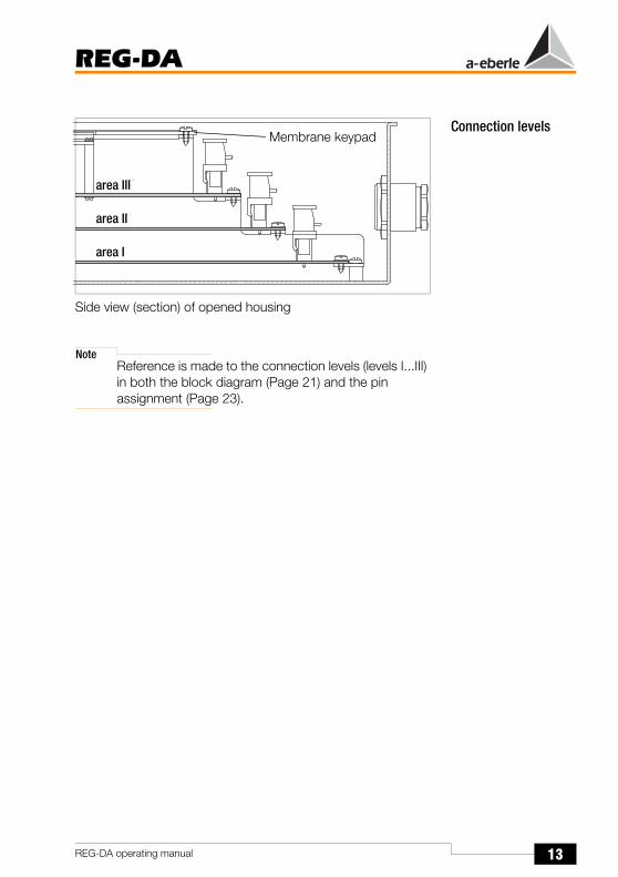
Connection levels
Side view (section) of opened housing
NoteReference is made to the connection levels (levels I...III) in both the block diagram (Page 21) and the pin assignment (Page 23).
Membrane keypad
area III
area II
area I

14
REG-DA
REG-DA operating manual
3.2 Connection diagram
Contact load R1, R2: AC 250 V, 5 A, cosϕ = 1, 250 V DC, 150 W
* Please observe the contact load at R1 and R2!(see below)!
** The connections for I and U can be freely assigned via the menu.
110 V DC 230 V AC20 A Switch on 5 A @ cosϕ = 1
5 A Hold 3 A @ cosϕ = 0.4
0.4 A Switch off

15
REG-DA
REG-DA operating manual
3.3 Overview of featuresREG-DA is a highly variable product.
The operating manual must take this factor into account and provide different descriptions for the for the various specifications.
Because the features ... M2, S1... D4 ... are noted on the name plate of the device, but the relation to the function which it stands for is not always given, the complete structure of the device's features is listed here.
Feature: ID
REG-DA Relay for Voltage Control & Transformer MonitoringBasic version with E-LAN double interfaces,COM 2, COM 3 and a mA input channel for e.g. measuring the oil temperatureor for the measuring of the tap-changer position using a measurement transducerwith 16 binary inputs and 12 relay outputs plus status outputinclusive of WinREG parameterisation software for parameterisation, programmingand displaying of all Relay for Voltage Control & Transformer Monitoring data incl. connecting cableNote: COM 2 is only freely accessibleif a log connection is not required.
REG-DA
DesignPanel-mounting or wall-mounting version(H x W x D) 307 x 250 x 102 mmwith standard mounting rail adapter
B0B1
Current supplyexternal85 V ... 110 V ... 264 V AC / 88 V ... 220 V ... 280 V DCexternal 18 V ... 60 V ... 72 V DC
H0H2
Input currents (can be changed later)IEN 1AIEN 5A
F1F2

16
REG-DA
REG-DA operating manual
Measurement transducer display functions for network quantitiesThree-phase current with balanced loadThree-phase current with unbalanced loadVoltage (HV-side), current and voltage (MV-side) measurementOther uses of the three current and two voltage transformers
M1M2M3
M9
Recorder functionsfor network quantities with evaluation softwareWithoutWith
S0S1
Transformer monitoringWithoutWith
T0T1
Parallel operationWithout firmware for parallel operationWith firmware for parallel operation
K0K1
Feature: ID

17
REG-DA
REG-DA operating manual
Additional analogue inputs and outputsWithoutWith one a PT 100 inputWith two mA inputsWith two mA outputsWith one PT 100 input and one mA outputWith two mA inputs and one mA outputWith three mA outputsTap-change potentiometer inputTotal resistance 200 Ohm ... 2 kOhmTap-change potentiometer inputTotal resistance >2 kOhm ... 20 kOhmOther combinations of inputs and outputs
Note about E91 ... E99:Please specify the scale if known!
Example: 1 -100 ... 0 ... +100 MW -20 ... 0 ... +20 mA
Example: 2 0 ... 80 ... 120 V4 ... 16 ... 20 mA
Example: 3 1 ... 19 levels0 ... 20 mA
Example: 4 50 ... 140°C4 ... 20 mA
E00E91E92E93E94E95E96
E97
E98E99
Feature: ID
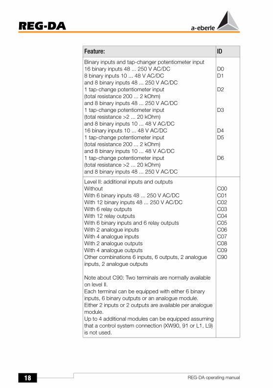
18
REG-DA
REG-DA operating manual
Binary inputs and tap-changer potentiometer input16 binary inputs 48 ... 250 V AC/DC8 binary inputs 10 ... 48 V AC/DC and 8 binary inputs 48 ... 250 V AC/DC1 tap-change potentiometer input (total resistance 200 ... 2 kOhm) and 8 binary inputs 48 ... 250 V AC/DC1 tap-change potentiometer input (total resistance >2 ... 20 kOhm) and 8 binary inputs 10 ... 48 V AC/DC16 binary inputs 10 ... 48 V AC/DC1 tap-change potentiometer input (total resistance 200 ... 2 kOhm) and 8 binary inputs 10 ... 48 V AC/DC1 tap-change potentiometer input (total resistance >2 ... 20 kOhm) and 8 binary inputs 48 ... 250 V AC/DC
D0D1
D2
D3
D4D5
D6
Level II: additional inputs and outputsWithoutWith 6 binary inputs 48 ... 250 V AC/DCWith 12 binary inputs 48 ... 250 V AC/DCWith 6 relay outputsWith 12 relay outputsWith 6 binary inputs and 6 relay outputsWith 2 analogue inputsWith 4 analogue inputsWith 2 analogue outputsWith 4 analogue outputsOther combinations 6 inputs, 6 outputs, 2 analogue inputs, 2 analogue outputs
Note about C90: Two terminals are normally available on level II.Each terminal can be equipped with either 6 binary inputs, 6 binary outputs or an analogue module.Either 2 inputs or 2 outputs are available per analogue module.Up to 4 additional modules can be equipped assuming that a control system connection (XW90, 91 or L1, L9) is not used.
C00C01C02C03C04C05C06C07C08C09C90
Feature: ID

19
REG-DA
REG-DA operating manual
Integrated control system connection according to: IEC61850 or IEC 60870- 5-104WithoutIEC 60850 - 5 - 104 (more in feature group “G”)Note: Please specify the target system for connections according to IEC 60850-5-104IEC 61850 (more in feature group “G”)
XW00XW90
XW91
Integrated control system connection according to: IEC 60870- 5-101/ ..-103,…DNP…Without (more in feature group “G”)for the control system connection of a REG-DAFor the control system connection of multiple systems (REG-D/DA/DP, etc.)Note: L9 can only be combined with feature XW90, Z15 to Z19 and Z91.
L0L1L9
Type of connection:Copper RS 232RS 485 only for 2-wire operation
Fibre-optic cable with FSMA connection systemGlass fibre(Wavelength 800...900 nm, range 2000 m)Plastic fibre(Wavelength 620...680 nm, range 50 m)
Fibre-optic cable with ST connection systemGlass fibre(Wavelength 800...900 nm, range 2000 m)Plastic fibre(Wavelength 620...680 nm, range 50 m)
V10V11
V13
V15
V17
V19
Feature: ID

20
REG-DA
REG-DA operating manual
Log:IEC60870-5-103 for ABBIEC60870-5-103 for ArevaIEC60870-5-103 for SATIEC60870-5-103 for Siemens (LSA/SAS)IEC60870-5-103 for Sprecher AutomationIEC60870-5-103 for others
IEC60870-5-101 for ABBIEC60870-5-101 for IDSIEC60870-5-101 for SATIEC60870-5-101 for Siemens (LSA/SAS)IEC60870-5-101 for others
DNP 3.00LONMarkSPABUSMODBUS RTU
Z10Z11Z12Z13Z14Z90
Z15Z17Z18Z19Z91
Z20Z21Z22Z23
Operating ManualGermanEnglishFrenchSpanishItalianRussianOther
G1G2G3G4G5G6G9
Display textGermanEnglishFrenchSpanishItalianRussianOther
A1A2A3A4A5A6A9
Feature: ID

21
REG-DA
REG-DA operating manual
3.4 Block diagrams3.4.1 Block diagram for features D0/D1/D4
!
"#
"#!
"#!
"#
!
"#
"#
"#
$% &
'
(
(
(
(
!
(
)#
((
(
(('
( *$
(
+
(!,
(,
!
(
-* *
./ 0
!
($1 2# !3
($1 2# !3
2.40
2.50
/
(/
(/
(/
!
)#
(6#
6#
(65
(64
65
64
4
5
4
!
5
5
(
#7!
5
4
5
4
5
4
5
4
5
8/
/
)#
/
9#
(/
(9#(/
$:
;;
#7!
<
)#
)#
)#
)#
!
4
! "#
!
#$5&$
4
4
4
5
5
5
5
'
44
44
55
55
$
8
(
$
%
&&#
%&&#
%&&#
'&(
$
-$1''=$
&& $
&
;* *!!
./'
!!

22
REG-DA
REG-DA operating manual
3.4.2 Block diagram for features D2/D3
2#!!3
!
$% &
'
(
(
(
(
!
(
)#
((
(
(('
( *$
(
+
(!,
(,
!
-* *
./ 0
!
($1 2# !3
($1 2# !3
2.40
2.50
/
(/
(/
(/
!
)#
(6#
6#
(65
(64
65
64
4
5
4
!
5
5
(
#7!
5
4
5
4
5
4
5
4
5
8/
/
)#
/
9#
(/
(9#
(/
$:
;;
#7!
<
)#
)#
4
! "#
!
#$5&$
4
4
4
5
5
5
5
'
44
44
55
55
$
8
$
%
&&#
%&&#
%&&#
%&&#
(
45
>5
>4
5
'&(
$
-$1''=$
&& $
&
;* *
!
!
./'
!!

23
REG-DA
REG-DA operating manual
3.5 Pin AssignmentSignals with non-exposed voltages are connected first of all on level I.
All of the circuits on level I have a nominal insulation voltage of > 50 V and are therefore considered to be non-exposed in accordance with VDE 0110 (exception: resistance input, feature D2/D3).
Please observe this condition even if small voltages are present at the relay contacts or the binary inputs.
Terminal area on connection level III
Terminal area on connection level I
Terminal area on connection level II
24
REG-DA
REG-DA operating manual
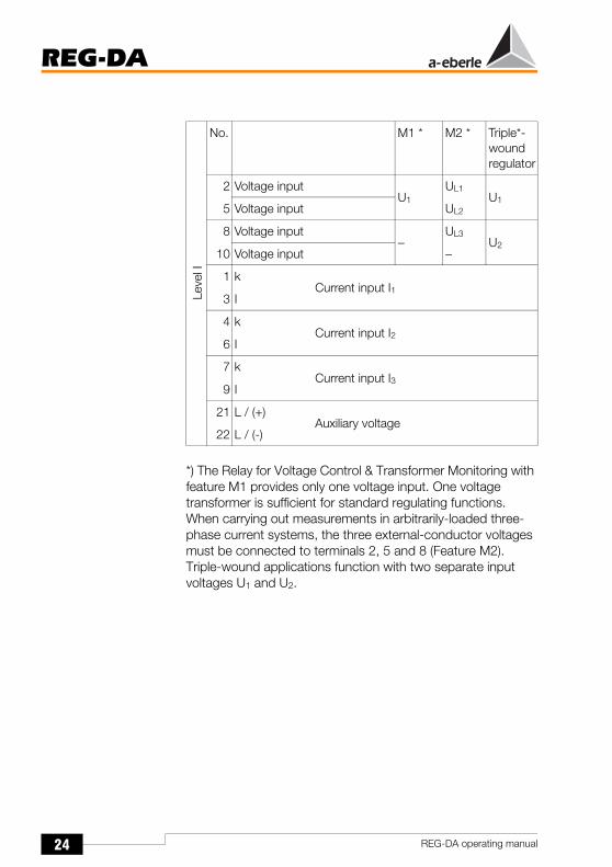
*) The Relay for Voltage Control & Transformer Monitoring with feature M1 provides only one voltage input. One voltage transformer is sufficient for standard regulating functions.When carrying out measurements in arbitrarily-loaded three-phase current systems, the three external-conductor voltages must be connected to terminals 2, 5 and 8 (Feature M2).Triple-wound applications function with two separate input voltages U1 and U2.
Leve
l I
No. M1 * M2 * Triple*-wound regulator
2 Voltage inputU1
UL1U1
5 Voltage input UL2
8 Voltage input−
UL3U2
10 Voltage input −
1 kCurrent input I1
3 I
4 kCurrent input I2
6 I
7 kCurrent input I3
9 I
21 L / (+)Auxiliary voltage
22 L / (-)

25
REG-DA
REG-DA operating manual
NoteAll of the inputs and relay outputs are freely programmable, with the exception of inputs 5 and 6 and the outputs R1, R2, R12 and R13. The assignment specified in the terminal diagram corresponds to the delivery state and can be changed if necessary.
Leve
l I
No. D0, D1, D4 D2, D3
11 Input 1 Tap-changer in progress
12 Input 2 Freely programmable
13 Input 3 Freely programmable
14 Input 4 Freely programmable
15 Input 1...4 GND
16 Input 5 AUTO / MANUAL - AUTO(see Page 127)
17 Input 6 MANUAL
18 Input 7 Freely programmable
19 Input 8 Freely programmable
20 Input 5...8 GND
23 Input 9 BCD 1
please also refer to Page 34
24 Input 10 BCD 2
25 Input 11 BCD 4
26 Input 12 BCD 8
27 Input 9...12 GND −
28 Input 13 BCD 10 −
29 Input 14 BCD 20 −
30 Input 15 BCD signal −
31 Input 16 Freely programmable −
32 Input 13...16 GND −

26
REG-DA
REG-DA operating manual
Leve
l I
No.
33Freely programmable R5
34
35Freely programmable R4
36
37Freely programmable R3
38
39
Lower R240
41
42
43
Raise R144
45
46
47 > I R11
48 >U R10
49 <U R9
50 Local R8
51 Remote R7
52 TC Error R6
53 GND R6...R11
54
Life contact (status)55
56
57 MANUAL
58
59 AUTO

27
REG-DA
REG-DA operating manual
Leve
l II
No.
IECLONDNP 3.0
SPA busModbus
For additional equipping possibilities for level II see "Pin assignment level II" on page 35.The connections of the control system can be found in the information attached to the operating manual.
Leve
l III
No.
63 mA input +A1 (standard equipment)
64 mA input -
61 Input or output
+
A262 Input or
output-
65 Input or output
+
A366 Input or
output-
67 Input or output
+
A468 Input or
output-
ϑ
65
66
68
Pt100

28
REG-DA
REG-DA operating manual
Leve
l III
No.
69 E-
E-LAN (L)70 E+
71 EA-
72 EA+
73 E-
E-LAN (R)74 E+
75 EA-
76 EA+
77 Tx +
COM 3 (RS 485)78 Tx -
79 Rx +
80 Rx -
81 du don’t use
82 TxD
COM 2 (RS 232)
83 RxD
84 RTS
85 CTS
86 GND

29
REG-DA
REG-DA operating manual
3.5.1 Pin assignment level I
3.5.1.1 Auxiliary voltage, current input and voltage input
Terminals 21, 22 and 1 to 10
The REG-DA Relay for Voltage Control & Transformer Monitoring is equipped for carrying out measurements in arbitrarily loaded three-phase current networks. Therefore, up to three current transformers are available.
Voltage regulation generally only requires a single-phase connection (one delta or phase voltage and one line current), because it may be assumed that the network conditions at the transformer are approximately symmetrical (feature M1).
If a more precise measurement of the outputs (P, Q, S) is required, it is possible to switch over to the Aron circuit. In this case, two voltages and two currents must be connected (feature M2).
The third current input is reserved for special cases, which must be coordinated before the device is delivered.
!
2.40
2.50
<
8

30
REG-DA
REG-DA operating manual
Auxiliary voltage (terminals 21 and 22)The protective earth must be connected first, because the REG-DA is a device with degree of protection I.
A plug-in shoe (6.3 x 0.8 mm) is provided in the lower part of the housing for connecting the protective earth.
The auxiliary voltage is supplied via the twin connector block (terminals 21 and 22).
Two types of power supply units are available:
Therefore, please ensure that the intended supply voltage corresponds to the auxiliary voltage of the device as stated on the printed nameplate, before connecting.
Feature H0:Both direct and alternating voltages may be connected.Ranges: 88 V ... 220 V ... 280 V DC
85 V ... 110 V ... 264 V AC
Power consumption: < 15 VA
Feature H1:18 V ... 60 V ... 72 V DC
Power consumption: < 10 W
The auxiliary voltage, and thus the power supply of the device, is protected by a T2L 250 V microfuse.The fuse holder can be opened with a screwdriver. The device is supplied with a spare fuse.
Flat-plug connection for protective earth
31
REG-DA
REG-DA operating manual
NotePlease note that the fuse catch should never be screwed on without having a fuse inserted, because otherwise it is difficult to open the fuse holder.
3.5.1.2 Control voltage
(Terminals 2, 5 and 8, 10)The control voltage must be connected to the terminals 2 and 5.
Any voltage from the three-phase current network can be used as the control voltage. The type of voltage (delta or phase voltage, UL1L2, UL2L3, UL3L1, U1N, U2N, U3N) must be communicated to the Relay for Voltage Control & Transformer Monitoring via the menu (SETUP 5, F2).
The permissible nominal application range of the control voltage ranges from 60 to 140 V and is expressed in terms of delta voltage.
If there is a connection between the phase and N, the nominal application range of 34.6 to 140 V becomes available.
Please note that a single-pole high-resistance earth connection affects L1 like a voltage dip if only a phase voltage (e.g. L1N) is available for measuring the actual value of the voltage.If a phase voltage is used as the control voltage rather than the recommended delta voltage, you must pay attention to the behaviour if a single-pole earth fault occurs.In high-resistance faults, situations may occur where the voltage appears to be too high or too low.The Relay for Voltage Control & Transformer Monitoring generally switches itself into standby mode for low resistance faults.
Strongly distorted signals may also be connected by means of a complex filtering of the measurement voltages and the measurement currents.
If feature M2 is used, voltage UL1 must be connected to terminal 2, voltage UL2 to terminal 5 and voltage UL3 to terminal 8.
i.e.: UL1 → 2UL2 → 5 UL3 → 8

32
REG-DA
REG-DA operating manual
Voltage inputs U1 and U2 are both available for triple-wound applications.
In each case, this is a special version for the triple-wound application, each of which is described separately.
3.5.1.3 Current inputs
(Terminals 1, 3 and 4, 6 and 7, 9)A connection to a power supply is not required for normal regulator operation.
In many cases, however, the voltage must be raised and/or lowered according to the respective load.It is necessary to connect the current transformer I1 (1 and 3) to carry out this additional task.
However, even without current-dependent regulation, we recommend connecting the current, because this means that network can be measured and displayed in the measurement transducer mode.
Ensure that the correct connection (k, l!) is used when connecting the current transformer.
Two current transformers must be connected for carrying out measurements in arbitrarily loaded three-phase networks.
The third current can be calculated on the basis of both of the measured currents. The third current connection (4, 6) is reserved for special cases, which will be described separately.
The changeover from 1 A to 5 A or vice-versa is accomplished via the menu. The use of hardware such as a bridge or jumper is not necessary.
Caution!Please observe that the line(s) must be short-circuited before releasing the lines on terminals 1/3, 4/6 and 7/9.

33
REG-DA
REG-DA operating manual
3.5.1.4 Relay outputs
(Terminals 33 ... 59)The REG-DA Relay for Voltage Control & Transformer Monitoring has 13 relays.
Relay 13 is used as a life contact and monitors the running of the processor as well as the supply voltages of the system.
Relays 1 ... 12 are available for regulating and controlling the transformer.
Relays R1, R2 and R12 are permanently assigned to specific functions, whereas all of the other relays are freely programmable. The relays are programmed with frequently used functions when delivered.
R1 ... R13: Potential-free relay contactsLoad: 250 V AC, 5 A, cosϕ = 1,
250 V DC, 150 W (also refer toPage 14)
Relays R1 and R2 may be switched as follows in order to lock a control command:
(
(
(
(
!
(
)#
((
(
(' (
*$(
+(
,(!
,(
!
-* *
./ 0
( $ 1 5 2 # ! 3
( $ 1 5 2 # ! 3
:
(
%
&&#
-$
R1
Raise
R2
Lower

34
REG-DA
REG-DA operating manual
3.5.1.5 Binary inputs, feature D0/D1
(Terminals 11 ... 32)The REG-DA Relay for Voltage Control & Transformer Monitoring has 16 binary inputs.
Only inputs 5 and 6 (Manual/Automatic) are permanently assigned. All of the other inputs can be programmed freely. Frequently used input functions are already assigned to some of the inputs when it is delivered (see table on page 24 to page 26).
3.5.1.6 Binary inputs and resistance inputsfor tap-change potentiometer (D2/D3)
(Terminals 11 ... 26)Only binary inputs 5 and 6 (Manual/Automatic) are permanently assigned. All of the other binary inputs can be programmed freely. Frequently used input functions are already assigned to some of the inputs when it is delivered (see table on Page 24 to Page 26).
Feedback of the tap-change position is often sent back to the Relay for Voltage Control & Transformer Monitoring as a BCD code.The binary inputs are parameterised to correspond with the number of steps in this case (see "Binary inputs, feature D0/D1" on page 34, terminals 23 to 32).
!
"#
"#!
"#!
"#
!
"#
"#
"#
)#
)#
)#
)#
!
%
&&#

35
REG-DA
REG-DA operating manual
If the tap-change position is supplied as a resistance value (e.g. 10 Ohm / tap-change position), the resistance module can be connected directly to terminals 23 to 26.
For further information see "Resistance Measuring Equipment for Tap-Changers with Resistance-Coded Tap-Change Signalling" on page 187:
3.5.2 Pin assignment level IILevel II is not equipped in the standard version of the Relay for Voltage Control & Transformer Monitoring.
However, a larger number of additional inputs and outputs can be provided via this connection level if additional binary or analogue inputs/outputs are required.
The equipment changes according to features C01 to C99.
A total of four different modules are available, that can be used in any combination if required.
Module 1: 6 binary inputs
Module 2: 6 relay outputs
Module 3: 2 mA inputs
Module 4: 2 mA outputs
The connection assignment of the individual features can be found in the terminal diagram.
2 # ! ! 3
!
)#
)#
%
&&#
(
4 5
>5
>4
5

36
REG-DA
REG-DA operating manual
Feature C016 additional binary inputs 48 ... 250 V AC/DC
Feature C0212 additional binary inputs 48 ... 250 V AC/DC
No.
Mod
ule
1
100 Binary input E17
101 Binary input E18
102 Binary input E19
103 Binary input E20
104 Binary input E21
105 Binary input E22
106 GND E17 ... E22
No.
Mod
ule
1
100 Binary input E17
101 Binary input E18
102 Binary input E19
103 Binary input E20
104 Binary input E21
105 Binary input E22
106 GND E17 ... E22
Mod
ule
1
107 Binary input E23
108 Binary input E24
109 Binary input E25
110 Binary input E26
111 Binary input E27
112 Binary input E28
113 GND E23 ... E28

37
REG-DA
REG-DA operating manual
Feature C036 additional relay outputs (NO contacts)
Feature C0412 additional relay outputs (NO contacts)
No.
Mod
ule
2
100 R14
101 R15
102 R16
103 R17
104 R18
105 R19
106 GND R14 ... R19
No.
Mod
ule
2
100 R14
101 R15
102 R16
103 R17
104 R18
105 R19
106 GND R14 ... R19
Mod
ule
2
107 R20
108 R21
109 R22
110 R23
111 R24
112 R25
113 GND R20 ... R25

38
REG-DA
REG-DA operating manual
Feature C056 additional binary inputs 48 ... 250 V AC/DC and6 relay outputs (NO contacts)
Feature C062 additional analogue inputs
No.
Mod
ule
1100 Binary input E17
101 Binary input E18
102 Binary input E19
103 Binary input E20
104 Binary input E21
105 Binary input E22
106 GND E17 ... E22
Mod
ule
2
107 R14
108 R15
109 R16
110 R17
111 R18
112 R19
113 GND R14 ... R19
No.
Mod
ule
3
100 Analogue input
+ E10
101 -
102 Analogue input
+ E11
103 -

39
REG-DA
REG-DA operating manual
Feature C074 additional analogue inputs
Feature C082 additional analogue outputs
Feature C094 additional analogue outputs
No.
Mod
ule
3
100 Analogue input
+ E10
101 -
102 Analogue input
+ E11
103 -
Mod
ule
3
104 Analogue input
+ E12
105 -
106 Analogue input
+ E13
107 -
No.
Mod
ule
4
100 Analogue output
+ A10
101 -
102 Analogue output
+ A11
103 -
No.
Mod
ule
4
100 Analogue output
+ A10
101 -
102 Analogue output
+ A11
103 -
Mod
ule
4
104 Analogue output
+ A12
105 -
106 Analogue output
+ A13
107 -

40
REG-DA
REG-DA operating manual
The hardware for all the control system connections is also contained on level II. The corresponding connection elements on level II must be used for RS232 or RS485 connections. If the Ethernet connection is used (required for IEC 61850 or IEC 60870-5-104 connections!), the corresponding connection is also accessible on level II. Please refer to the configuration documentation supplied with this operating manual, since the terminal assignment can be very different for the individual interfaces.The connection elements for fibre-optic cables (send and receive diodes as ST or FSMA connection) are mounted directly on the flange plate and can be connected there without opening the device.
Fibre-optic cable connection(FSMA-connection system)
Fibre-optic cable connection(ST-connection system)

41
REG-DA
REG-DA operating manual
3.5.3 Pin assignment level IIIIt is possible to access interfaces COM 1, COM 2 and COM 3 via level III.
The connection elements for the E-LAN transport bus and certain combinations of analogue inputs and outputs (Features E91 to E99) are also available via level III.
Interface COM 1
Function Pin
DCD 1
RXD 2
TXD 3
DTR 4
Signal-Ground 5
DSR 6
RTS 7
CTS 8
RI 9
)#
/
9#
(/
(9#
( /

42
REG-DA
REG-DA operating manual
Equipping analogue inputs is dependent on the selected structure of the features.
Both mA inputs and mA outputs may be implemented.
A module can be supplied for measuring the oil temperature (transformer monitoring), which can be directly attached to a PT 100.The connection is designed as a three-conductor circuit and can be used over a distance of approximately 100 m.
The inputs can operate continuously in a short-circuited or open state. All inputs are electrically isolated from all of the other
/
(/
( /
( /
!
)#
(6#
6#
(65
(64
65
64
4
5
4
!
5
5 (
5
4
5
4
5
%
&&#
COM 2, suitable for connecting:- Modem- PC- DCF 77- E-LAN-L- E-LAN-R
COM 3, only suitable for connecting BIN-D and ANA-D interface components!
$ % &
'
4
# $ 5 & $
4 4 45 5 5 5
'
4 4 4 4 5 5 5 5
$
%
&&#
optional
43
REG-DA
REG-DA operating manual
circuits. The Relay for Voltage Control & Transformer Monitoring is equipped with one analogue input as standard. The type of use can be specified at the time of ordering, or a specific measurement quantity can be assigned using WinREG or the device's keyboard.
The outputs can operate continuously in a short-circuited or open state. All outputs are electrically isolated from all of the other circuits.

44
REG-DA
REG-DA operating manual
3.6 Types of REG-DA Relay for Voltage Control & Transformer Monitoring
3.6.1 Wall-mounting version
The mounting bars provided must be screwed onto the rear of the device.
The entire unit must be attached with suitable screws to/onto a stable mounting surface.
If the mounting holes are drilled laterally, both mounting bars can also be folded inwards (see shaded area).
NotePlease note and use the enclosed hole pattern (last page).
Mounting bars
Dimensions in mm

45
REG-DA
REG-DA operating manual
3.6.2 Panel-mounting version
After the cutout has been cut in the mounting panel, the four grub screws (1) must be screwed into the bottom of the housing. The device is then pushed through the cutout and is fixed with the two clamping angles (2).
In general, it is advisable to remove the flange plate first, then push the housing through the cutout.
(1)
(2)(2)
(1)

46
REG-DA
REG-DA operating manual
3.6.3 Mounting on Standard Mounting Rails
The Relay for Voltage Control & Transformer Monitoring can also be mounted on 35 mm standard mounting rails.

47
REG-DA
REG-DA operating manual
4 Operation
4.1 Display and control elements
The MPC operation level (people-process communication) of the REG-D Relay for Voltage Control & Transformer Monitoring is implemented as a membrane keypad with integrated light-emitting diodes (LEDs).
Indicators and labelsSeven labels are available. Each label is designed for two signals (2 LEDs).
The labelling of each individual field may be changed at any time by pulling the label strip downwards out of the clear vinyl pocket.
Function keys
Indicators
Field
Label
Parameterisation
FieldTransformer control
LCD displayLEDField 1
LEDField 7
.
.
.
.
.
.
.
.
Label strips

48
REG-DA
REG-DA operating manual
NoteFurther label strips can be found in Annex 2.A program for generating label strips called Beschriftungsprogramm.xls can be found on the program CD.If you have a colour printer at your disposal, the individual fields can even be printed in colour (yellow and red).
Any standard pen can be used to write on the labels.
Indicator 1 is programmed as default and cannot be changed.
LED 1 in field 1 (green) lights up when the device is operating fault-free (service).
LED 2 in field 1 (red) lights up when the device has a fault (blocked).
The LEDs in field 2 to field 5 (yellow) are freely programmable for general signalling, and are not programmed when delivered.
The LEDs in field 6 to field 7 (red) are freely programmable. They are primarily intended for fault signals and are not programmed when delivered.
Transformer control panel7 keys are assigned to the transformer control panel.
The “AUTOMATIC” key with an integrated green LED lights up when the Relay for Voltage Control & Transformer Monitoring is functioning in the Automatic operating mode.
The “Manual” key with integrated red LED lights up when the Relay for Voltage Control & Transformer Monitoring is functioning in the manual mode.
The arrow keys “Raise” and “Lower” can be used to manually select the taps of the transformer.Prerequisite: The “LOCAL” key (red) is activated.
All remote control commands via binary inputs or a serial connection are suppressed when in the “LOCAL” setting.
Remote control is only possible in the “REMOTE” mode (green).
49
REG-DA
REG-DA operating manual
The REG-DA Relay for Voltage Control & Transformer Monitoring was designed in such a way that all of the display elements of the transformer control panel (“Manual/Auto” and “Local/Remote”) have to be green when the operating personnel leave the control room.
The “ACK” key is currently still out of operation.
In the future, this key will be able to be used to acknowledge process signals and/or fault signals which the Relay for Voltage Control & Transformer Monitoring generates itself and indicates in the display.
Parameterisation panelThe keys in the parameterisation panel can be used to manually parameterise the REG-DA Relay for Voltage Control & Transformer Monitoring.
The “Menu” key is used to switch between the various operating modes and to select a specific parameterization menu (SETUP 1 ... SETUP 6)
The “Return” key is used to confirm a specific parameter in the SETUP menus.
NoteChanges to the parameterisation which are important for operation can only be carried out in the manual operating mode.
The “Esc” key is used to exit any menu. The user can move the cursor within the parameterisation menus using the
and keys.
Function keys
The function keys, “F1” to “F5” , are implemented as so-called softkeys.
The function of the keys is context-controlled and depends on the corresponding menu.

50
REG-DA
REG-DA operating manual
4.1.1 Display
LCD display
LCD Display Recorder Mode
Address at bus (station identification) Relay name Time
Setpoint value in Setpoint value in
regulative deviation
Backwards high-speed switching is indicated by “<--<”
„ACTUAL VALUE” in capital letters= measurement simulation is running
„ACTUAL VALUE” in small letters= measurement simulation is off
Actual value in V/
er is transparent when the regulative deviation is lower than the permissible regulative deviation.pointer is black when the regulative deviation is higher than the permissible regulative deviation.
Identification lineStatus line
Progress bar (when active)
Address at bus (station identification) Relay name Time
Forward
Date
Present voltage
Feedrate
Identification line
Set permissibleregulative deviation
TimePresent voltage Tap-change
speed
Scale
Back
Menu recorder
Present feedrate speed(14s / scale section)
Present voltage
51
REG-DA
REG-DA operating manual
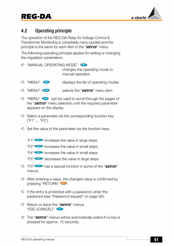
4.2 Operating principleThe operation of the REG-DA Relay for Voltage Control & Transformer Monitoring is completely menu-guided and the principle is the same for each item in the “SETUP” menu.
The following operating principle applies for setting or changing the regulation parameters:
“MANUAL OPERATING MODE” changes the operating mode tomanual operation
“MENU” displays the list of operating modes
“MENU” selects the “SETUP” menu item
“MENU” can be used to scroll through the pages of the “SETUP” menu selection until the required parameter appears on the display.
Select a parameter via the corresponding function key(“F1” ... “F5”).
Set the value of the parameter via the function keys.
“F1” increases the value in large steps
“F2” increases the value in small steps
“F4” increases the value in small steps
“F5” decreases the value in large steps
“F3” has a special function in some of the “SETUP” menus.
After entering a value, the changed value is confirmed by pressing “RETURN” .
If the entry is protected with a password, enter the password (see "Password request" on page 95).
Return or leave the “SETUP” menus “ESC (CANCEL)”
The “SETUP” menus will be automatically exited if no key is pressed for approx. 15 seconds.

52
REG-DA
REG-DA operating manual
The REG-DA Relay for Voltage Control & Transformer Monitoring can be switched back to the automatic operating mode using “AUTO” once the required parameters are entered, checked and individually confirmed by pressing the “RETURN” key.
4.3 Selecting the display modeThe display modes of the REG-DA Relay for Voltage Control & Transformer Monitoring can be selected after pressing the
“MENU” key.
The following modes are available:
Regulator Mode
Measurement transducer mode
Recorder mode
Statistics mode (Monitor mode)
ParaGramer mode
Regulator Mode The “F1” key is used to select the “Regulator Mode”.
The display indicates the set setpoint value in V (kV) and as a percentage of the nominal voltage, the momentary actual value, the value of the permissible regulative deviation and the present tap-changer position of the tap-changing transformer.
The present deviation of the setpoint is also indicated on a scale (by an
analogue pointer) with a bandwidth of ± 10%.
The colour of the scale’s pointer changes from transparent to black if the specified permissible regulative deviation is overshot or undershot.

53
REG-DA
REG-DA operating manual
If required, the present value of the current may also be displayed.
NoteIf “Actual Value” is displayed in capital letters, i.e. “ACTUAL VALUE”, then the “MEASUREMENT VALUE SIMULATION” is active!(see Page 146).
Measurement transducer mode
The “F2” key is used to select the “Measurement Transducer Mode”.
When the Relay for Voltage Control & Transformer Monitoring carries out measurements in the Aron circuit (feature M2), a second measurement transducer screen can be selected to display the measured values of the three-phase current networks loaded according to the requirements of the user.
NoteIn the measurement transducer mode, only the reactive current I sinϕ of each transformer will be displayed. However, it is not possible to determine on the basis of this display which share of the current pertains to the load and which pertains to the reactive current.
The second measurement transducer screen can be selected
by pressing either the or key.

54
REG-DA
REG-DA operating manual
The third transducer screen may be selected by pressing either
the or key.
If the device is switched in parallel, it is advantageous to display the circulating reactive current as well.
The circulating current Icirc provides information about the share of the current that is “circulating” in the parallel-switched transformers and not taken up by the load.
The quasi-analogue scale illustrates the relationship between the circulating reactive current “Icirc” and the permissible circulating reactive current “perm. Icirc”.
If the permissible Icirc is 50 A, the circulating reactive current Icirc is actually -100 A and the value -2 is shown on the scale.
If the circulating current becomes zero, the quotient will also become zero and the pointer will be positioned in the middle of the scale.
However, generally speaking, this ideal situation can in practice only then be reached when the parallel-switched transformers exhibit the same electrical features.
Recorder mode The “F3” key is used to select the “Recorder Mode”.
As standard, every Relay for Voltage Control & Transformer Monitoring is equipped with a DEMO recorder (feature: DEMO in the lower left corner of the grid).
Above the grid, the set permissible regulative deviation is displayed by means of two black arrows. In this manner, the recorder display is capable

55
REG-DA
REG-DA operating manual
of supplying all of the information needed for operating the Relay for Voltage Control & Transformer Monitoring (see "LCD Display Recorder Mode" on page 50).
In addition to the value of the present voltage and the tap-changer position (in the lower left-hand corner), the display also indicates the permissible regulative deviation (black arrows above the grid) and the change of the voltage over a period of time (past values).
Within the grid, the present voltage is the value which intersects the lower line of the two parallel border lines at the top of the grid.
Independent of the selected feedrate speed (F4), the memory stores values at a constant rate of 1 second.
Each 1 second value is composed of 10 100ms values.
Seven scale divisions are available in total on the display. Thus, a maximum time range of 7 x 10 minutes (70 minutes) may be shown on the screen.
The shortest time range with the biggest optical resolution is 7 x 14 seconds (98 seconds).
Apart from the voltage, the recorder can also record the current and the angle ϕ. The tap-changer position and the setpoint value with tolerance band are always recorded as well.
In the second recorder menu (F3-F3), the desired mode can be selected via the menu item “Number of channels” (F4). It is possible to change modes at any time without loss of data.
Displaying the recorder dataIn the first recorder menu (F3), the menu item “Dual Display” (F4) can be used to switch the recorder display between the one-channel display of U and the two-channel display. The left channel is always reserved for the control voltage U. The Relay for Voltage Control & Transformer Monitoring offers a selection of measurement quantities for the second channel (see 2nd recorder menu).
The time axis is the same for both curves. Only the resolution of the left channel can be changed using the “dx” (F5 key); the scale of the second channel remains the same.

56
REG-DA
REG-DA operating manual
Derived variables from the recorder dataIn the first recorder menu (F3,F3), the menu item “MMU display” (F5) can be used to switch the display of variables derived from the present cursor value (at the very top) on and off.I and S are displayed as numeric values if only two recorder channels (U + I) have been selected (second recorder menu (F3, F3, F4)).
If all three recorder channels (U + I + ϕ) are activated, then I, ϕ, P and Q will be displayed as numeric values.
It is also possible to search for an event in the second recorder menu. If both the date and the time of a certain event are known, a specific day and time can be selected in the “Time Search” submenu.
After returning to the recorder main menu (by pressing F3 or Enter), the recorder lists the selected time and displays all of the electrical measurement values as well as the corresponding tap-changes.
Statistics mode The “F4” key is used to select the “Statistics Mode”.
The total number of tap-changes made since the counter was last set to zero is shown on the display. Thus tap-changes made under load and tap-changes made with a load of less than 5% of the nominal current In (1 A or 5 A) are distinguishable.
Changes made under load are additionally displayed for each tap-
change.
NoteIf the tap-changer is working under load (I > 0.05 ⋅ In), a double arrow >> indicates the present tap-changer position.If the load condition is not fulfilled, the present tap-changer position will be indicated by a single arrow “>”.
In conjunction with the recorder, the statistics mode provides valuable information regarding the controlled system.

57
REG-DA
REG-DA operating manual
The parameters “Time factor” and “Permissible regulative deviation” can be used to reach an optimum between the voltage stability and the number of tap-changes. However, this relation cannot be calculated mathematically as it is subject to the individual conditions at the respective feeding point.
ParaGramer “F5” selects “ParaGramer mode”.
The ParaGramer is a tool used for automatically preparing parallel connections and for the one-line display of the switching status.
The artificial word ParaGramer is derived from the terms parallel and one-line diagram.
The ParaGramer displays the switching status of the individual transformers in one-line graphics and can be loaded by pressing the F5 key in the main menu.
The function is activated by feeding a complete busbar replica (positions of the circuit breakers, disconnectors, bus ties and bus couplings) into each Relay for Voltage Control & Transformer Monitoring by means of binary inputs.
On the basis of the switching statuses, the system can independently recognise which transformer should work in parallel operation with which other transformer(s) on a busbar.
The system treats busbars connected via bus couplings as one single busbar.
As shown in the graphic, both transformers T1 and T3 are working on busbar “a”, whereas transformer T2 is feeding on busbar “b”.
If special crosslinks are needed between the busbars, we recommend that you contact the headquarters of our company A. Eberle GmbH & Co. KG for assistance, since it is not possible to describe all the options in this operating manual.
The “crosslinks” feature is depicted in the graphic. With its assistance, two busbars may be coupled crosswise.
Crosslink

58
REG-DA
REG-DA operating manual
Setup menus “MENU” selects the “SETUP” menü 1
4.4 Lamp check
Press the “F5” key to check the functions of the light-emitting diodes on the front panel. Select “F5” .
NoteThis check can only be carried out in the “Regulator Mode” or “Statistics Mode”.
4.5 Resetting fault signalsTo reset fault signals that occur, the operating mode must be changed from AUTOMATIC to MANUAL and then back to AUTOMATIC again.
4.6 Operating the recorder
“F1” and “F2” allow access to historical values.
The time and date corresponding to a particular event can be found by setting the voltage-time diagram back to the time-reference line (beginning of the grid at the top) using the “F1”
and “F2” keys. The time, date, voltage value and tap-changer position can then be read below the grid.
If historical data is displayed, the term “HIST” appears in the lower left-hand corner of the grid. Display of past measurement values may be aborted at any time by pressing the “ESC
(CANCEL)” key.
Press “F3” to go to the recorder 1 menu. The scroll displacement for searching using the “F1” and
Time reference line

59
REG-DA
REG-DA operating manual
“F2” keys (in recorder mode) can be set using the “scroll” menu item. This helps to speed up the search procedure. It is also possible to switch back and forth between “Dual Display” and “MMU display” in the Recorder -1 menu.
Pressing the “F3” key in the Recorder -1 menu will take you to the Recorder -2 menu. In this menu a specific search date and time can be set under the menu item “Time Search”. The type of display (U, U+I, U+I+Phi, U+U2, U+OilT, U+WndT) can be selected under the menu item “Channel Display”.
The time-line diagram for the selected point in time appears after returning to the recorder mode again by pressing “F3”
.
The Recorder 1 and Recorder 2 menus display the present memory capacity status in “%” as well as in “days”.
Õ
Õ
Õ
Õ
Õ
Õ

60
REG-DA
REG-DA operating manual
The feedrate speed can be selected by pressing the “F4” key. Four different times can be selected: 14 s, 1 min, 5 min, 10 min.
Õ
Õ Õ
Õ
Õ
Õ
Õ
Õ

61
REG-DA
REG-DA operating manual
The “dt” values refer to the time which must pass before a scale section (division) is recorded.
The scale of the 1st channel can be changed using the
“F5” “dx” key.
An extension of WinREG permits the data to be read out.
The data may be archived on the PC from firmware version 1.78 onwards.
The evaluation program can also generate data records that can be read by MS EXCEL.
NoteIf the note “DEMO” appears in the lower left-hand corner of the grid of the regular recorder display, the recorder is operating in demo mode. In this operating mode, the recorder only records the measured values for a period of 4 - 6 hours. After this period, the older values are replaced by the new ones.
dT = 14sdT = 1mdT = 5m
dT = 10m
1 division

62
REG-DA
REG-DA operating manual
63
REG-DA
REG-DA operating manual
5 Commissioning
The REG-DA Relay for Voltage Control & Transformer Monitoring is a complex device with many functions.
This variety of functions necessitates a comprehensive operating manual.
It was considered whether it was better to fill the individual screenshots with all the theoretical information, or whether it is better to separate the two parts by summarising the background information and guiding the reader through the individual screens.
We finally decided to offer two separate parts with the corresponding cross-references.
However, in order to make it as easy as possible to start the parameterisation without constantly having to jump between two sections, we have inserted a commissioning section which enables a standard voltage regulation to be carried out step-by-step.
Thus we based the description on the most important functions of voltage regulation.
A summary of the limit values with a short explanation and links to the appropriate chapters can be found on Page 85
Whilst the parameterisation can be implemented using the WinREG parameterisation program, this chapter only deals with parameterisation using the device keypad.
The parameters that are particularly important for voltage regulation will be briefly mentioned in seven steps and the parameterisation explained.Further settings that are required in special cases can be found in chapter 7.
After applying the operating voltage, theREG-DA will indicate that it is in regulator mode.
Other modes, such as measurement transducer mode, recorder mode, statistics mode and ParaGramer mode, can be selected at any time.

64
REG-DA
REG-DA operating manual
Therefore it is important to realise that all modes run parallel to each other in the background. If one selects the recorder mode (for example), the regulating tasks and all the other parameterised task settings will also naturally be processed.
Press MENU and then use the keysF2 ... F5 to select the desired mode.
The individual operating modes are briefly described below.
In total, six SETUPs are designed for the parameterisation.You can scroll through the individual SETUPs in the following manner:
Starting at the main menu (regulator, measurement transducer, recorder, statistics or ParaGramer), press MENU to enter SETUP 1.
Repeatedly pressing the MENU key selects SETUP 2 to SETUP 6.
If you are already in one of the SETUPs, you can reach all the other menus by pressing the ← and → keys.
Caution!Please observe the “Warnings and Notes” on Page 9 without fail!

65
REG-DA
REG-DA operating manual
5.1 Regulator mode
After the auxiliary voltage is applied, the Relay for Voltage Control & Transformer Monitoring indicates that it is in regulator mode.
The important parameters for assessing a regulation situation are shown in this display mode.
The tap-changer position and the present regulative deviation are shown in addition to the actual voltage value. The present regulative deviation is shown in quasi-analogue form.
If the pointer is at “0” the actual value is the same as the setpoint value. If the regulative deviation is within the tolerance range the pointer is transparent. If the regulative deviation is outside the permissible regulative deviation the pointer changes to black.
In this way one can judge the present condition of the controlled system at a glance.
An alternative display with additional information − the compact display − can be selected using the F1 key.
In addition to the actual value and the tap-changer position, the setpoint value in V (kV) and % as well as the permissible regulative deviation in % are shown in this display.
If you prefer the large display, simply press the F1 key again.

66
REG-DA
REG-DA operating manual
5.2 Measurement transducer mode
Press MENU and then select the measurement transducer mode using the F2 key.
Various important measurement quantities are shown in this mode.
The voltage, current and frequency are independent of the connection of the measurement quantities, whereas the outputs can only be displayed correctly when the measurement sources are correctly entered.
The Relay for Voltage Control & Transformer Monitoring with feature M1 only gives exact measurement values in equally loaded 3-phase networks. In this case, the measurement transducer emanates from a symmetrical loading of all lines, and measures only one current and one voltage.
For this reason, the Relay for Voltage Control & Transformer Monitoring must know the source of the voltages (L1L2, L2L3, L3L1) and currents (L1, L2, L3) in order to be able to take the angle between the input quantities into consideration.
If measurements are to be taken in a 3-phase network loaded according to the requirements of the user, the Relay for Voltage Control & Transformer Monitoring must be equipped with feature M2.
NoteThe I x sin ϕ current is particularly important for parallel-switching transformers.
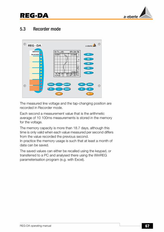
67
REG-DA
REG-DA operating manual
5.3 Recorder mode
The measured line voltage and the tap-changing position are recorded in Recorder mode.
Each second a measurement value that is the arithmetic average of 10 100ms measurements is stored in the memory for the voltage.
The memory capacity is more than 18.7 days, although this time is only valid when each value measured per second differs from the value recorded the previous second.In practice the memory usage is such that at least a month of data can be saved.
The saved values can either be recalled using the keypad, or transferred to a PC and analysed there using the WinREG parameterisation program (e.g. with Excel).

68
REG-DA
REG-DA operating manual
5.4 Statistics mode
In statistics mode, tap-changes under load and tap-changes when idling are differentiated and recorded separately.
The load condition is fulfilled if a current is measured that is 5% larger than the entered nominal value.(Example: for In = 1 A → 50 mA; for In = 5 A → 250 mA).
Under load conditions every tap-change is recorded and displayed.A double arrow before a particular change indicates that the transformer is running under load and is on the displayed level.A single arrow signals that the transformer is idling.

69
REG-DA
REG-DA operating manual
5.5 ParaGramer mode
The ParaGramer is a support tool for the automatic preparation of parallel connections and the online display of the switching statuses.
The artificial word ParaGramer is derived from the terms parallel and one-line diagram.
The ParaGramer displays the switching status of the individual transformers in one-line graphics and can be loaded by pressing the F5 key in the main menu.
The function is activated by feeding a complete busbar replica (positions of the circuit breakers, disconnectors, bus ties and bus couplings) into each Relay for Voltage Control & Transformer Monitoring by means of binary inputs.
On the basis of the switching statuses, the system can independently recognise which transformer should work in parallel operation with which other transformer(s) on a busbar.
Busbars that are connected via bus coupling(s) are treated as one single busbar by the system.
As shown in the graphic, both transformers T1 and T3 are working on busbar “a”, whereas transformer T2 is feeding on busbar “b”.

70
REG-DA
REG-DA operating manual
5.6 Choosing the languagePlease select SETUP 5, F1, F1
Press F5 to view all of the selectable languages.
Select the desired language with F2 or F4 and confirm the selection using F3.
5.7 Setpoint valueThe REG-DA Relay for Voltage Control & Transformer Monitoring can manage up to four setpoint values.
However, in general only one fixed value is used.
Please select SETUP 1, F3, F2.
The setpoint value can be increased using F1 and F2 and decreased using F4 and F5.
Press the F3 key if the setpoint value entered should be interpreted as a 100% value.
Press Enter to store the settings.
Õ
Õ
2 x

71
REG-DA
REG-DA operating manual
NoteIf the transformer mounting ratio (Knu) of the voltage transformer is specified in a procedure carried out later, then the primary voltage appears in kV in the second row of the setpoint menu.
5.8 Permissible regulative deviation Xwz
There are two limits for setting the regulative deviation.
One limit is determined from the acceptable voltage tolerance specified by the consumer, the other is defined by the tap-change increment of the transformer.
The minimum voltage range can be calculated using the following equation:
Xwz: Permissible regulative deviation
If a regulative deviation Xwz that is smaller than the tap-change increment of the transformer is selected, the controlled system can never reach a stable condition; the Relay for Voltage Control & Transformer Monitoring will continue to increment in steps.
Please select SETUP 1, F1.
The permissible regulative deviation can be increased using F1 and F2 and decreased using F4 and F5.
The parameter is confirmed by pressing Enter.
Xwz[%] ≥ 0.6 · tap-change increment[%]

72
REG-DA
REG-DA operating manual
5.9 Time behaviourThe golden rule for multiple feeding points is: a calm network
As a consequence, the Relay for Voltage Control & Transformer Monitoring should be set up in such a manner that as few switching operations as possible are carried out.
The Relay for Voltage Control & Transformer Monitoring can be calmed by increasing either the permissible regulative deviation (Xwz) or the time factor.
However, this course of action has its limits when the interests of the recipients are violated in an impermissible manner (voltage deviations are too large or last too long).
The standard defined reaction time tB must be changed when using the time factor option to influence the number of regulation events.
The default algorithm dU · t = const. ensures that small regulative deviations may be present for a long time, before a tap-change is triggered, whereas large deviations are rectified more quickly.
The time factor has been included as an option to influence the reaction time tB of the Relay for Voltage Control & Transformer Monitoring. The time factor is set to 1 as factory default. The time tB is multiplied with the time factor and the result is the reaction time tv of the Relay for Voltage Control & Transformer Monitoring.
The value of the time factor must be multiplied with the reaction time taken from the diagram.
tv = tB · time factor

73
REG-DA
REG-DA operating manual
Example:Present regulative deviationXw = 4%; Permissible regulative deviation Xwz = 2%tv = tB · time factor(range of the time factor: 0,1 ... 30see SETUP 1, F2, F3) → with time factor: 1: 15 sec; → with time factor: 2: 30 sec;
NoteIn practice, a time factor between 2 and 3 is used.However, a general recommendation cannot be given, since the correct time factor is dependent on both the network and the customer configuration.
Please select SETUP 1, F2, F3 and enter the time factor using F1, F2 and F4, F5.
Rea
ctio
n tim
e t B
[sec
] for
tim
e fa
ctor
: 1
25
20
15
10
5
00 1 2 3 4 5 6 7 8 9 10Present regulative deviation UW [%]
Set permissible regulative deviation

74
REG-DA
REG-DA operating manual
Confirm your choice by pressing Enter.
The REG-DA Relay for Voltage Control & Transformer Monitoring offers several time programs. In addition to the default-selected dU · t = const. integral method, the Relay for Voltage Control & Transformer Monitoring offers a fast integral method, a linear method and a further method working with a fixed times that can be found under the name CONST.
If CONST is selected, all regulative deviations that lie outside the tolerance band and that are smaller than the selected permissible deviation are rectified within time T1. For larger regulative deviations, however, the time will be T2.
Example:The selected permissible regulative deviation is ±1%.Reaction time T1 is valid in the range from 1% to 2%. The Relay for Voltage Control & Transformer Monitoring carries out tap-changes according to the time selected for T2 if the regulative deviation is larger than 2% (calculated from the setpoint value!).
For further information see Page 255.

75
REG-DA
REG-DA operating manual
5.10 Backward high-speed switchingWhile the Relay for Voltage Control & Transformer Monitoring is operating according to the algorithm dU · t = const., events will always be regulated such that the next tap-change will be triggered after a short time for large deviations and after a long time for small deviations.
Example:
The curve below gives a time of 42 s, the time within which the fault will be rectified.High-speed switching can be used to reduce this time.If, in the above example, the high-speed switching limit were set to 6%, the Relay for Voltage Control & Transformer Monitoring would switch the voltage back to the permissible range of the voltage tolerance band as soon as this limit is reached and the selected time delay for high-speed mode has passed.
Permissible regulative deviation Xwz: 1%
Present regulative deviation Xw: +6%
Time factor: 1
Tap-change increment of the transformer: 1,5%
Rea
ctio
n tim
e t B
[sec
] for
tim
e fa
ctor
: 1 25
20
15
10
5
00 1 2 3 4 5 6 7 8 9 10Present regulative deviation UW [%]
Tap-change 1
Tap-change 2
Tap-change 3
Tap-change 4Set permissible regulative deviation

76
REG-DA
REG-DA operating manual
Diagram:Present regulative deviationXw = 6%; Permissible regulative deviation Xwz = 1%tv = tB · time factor→ with time factor: 1:
1st tap-change after 5 s2nd tap-change after 7 s3rd tap-change after 10 s4th tap-change after 20 s________________________Total time = 42 s
Please select SETUP 3, F4 and select backward high-speed switching using F3. Then enter the desired limit as a % of the setpoint value.
Confirm your choice by pressing Enter.
The time delay can be set in SETUP 4, F4 after backward high-speed switching has been activated.
Confirm your choice by pressing Enter.

77
REG-DA
REG-DA operating manual
5.11 Tap-changer running timeIf the high-speed switching limit is reached, then the running time of the tap-changer determines the time required for the voltage to return to being within the tolerance band.
If the running time of the tap-changer is specified, other control signals can be prevented from being output when the tap-changer is running.
Old tap-changing devices in particular may occasionally respond with an EMERGENCY STOP signal, if a further control signal is input at the same moment that the tap-changer is changing to a new position.
The running time of the tap-changer can be entered in menu Add-On 1.
Please select SETUP 5, F1
If the Relay for Voltage Control & Transformer Monitoring is operating in high-speed switching mode, two seconds will be added to the entered running time. The Relay for Voltage Control & Transformer Monitoring will not issue a new control command until this entire running time has elapsed.
NoteThis function will be carried out by the (PAN-D) voltage monitoring unit if the unit is present in the regulating system.
Extension:Two further settings in SETUP 5 enable the running time of the tap-changer to be monitored.
The tap-change in operation lamp (TC) signal can be connected to one of the freely programmable inputs (E3 in this case).(SETUP 5, F3).

78
REG-DA
REG-DA operating manual
A freely programmable relay (in this case relay 5) can be used for fault reporting (TC-Err).
TC-Err+ → transmits a wiping signal in the event of a fault
TC-Err. → transmits a continuous signal in the event of afault
This signal can be used to stop the Relay for Voltage Control & Transformer Monitoring or turn off the motor drive.

79
REG-DA
REG-DA operating manual
5.12 Knx transformer mounting ratios and transformer connection
This point can be skipped if only the secondary transformer voltage is required for regulation and the transducer functions of the Relay for Voltage Control & Transformer Monitoring are not required.
In all other cases, the transformer mounting ratios and the “sources” of both the current and the voltage must be named.
If it is specified via the REG-DA menu that the current transformer is connected to external connector L3 and that the voltage to be measured is between L1 and L2, the Relay for Voltage Control & Transformer Monitoring corrects the 90° angle by itself and delivers the correct values for all the outputs and for the reactive current I · sin ϕ.
Please select SETUP 5, F2, F1
Select the source of the voltage that is to be regulated using F2 or F4 and confirm the selection by using F3 or Enter.
Knu is the quotient of the input voltage and the output voltage of the voltage transformer and ensures that the primary voltage is displayed (e.g. 20 kV and not 100V).
Select the transformer mounting ratio Knu using F2 or F4 and confirm the selection with the ENTER key.
Õ
Õ
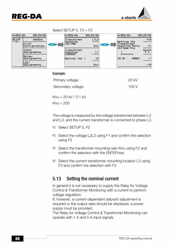
80
REG-DA
REG-DA operating manual
Select SETUP 5, F2 + F2
Example:
Knu = 20 kV / 0.1 kV
Knu = 200
The voltage is measured by the voltage transformer between L2 and L3, and the current transformer is connected to phase L3.
Select SETUP 5, F2
Select the voltage L2L3 using F1 and confirm the selection using F3
Select the transformer mounting ratio Knu using F2 and confirm the selection with the ENTER key
Select the current transformer mounting location L3 using F3 and confirm the selection with F3
5.13 Setting the nominal currentIn general it is not necessary to supply the Relay for Voltage Control & Transformer Monitoring with a current to perform voltage regulation.If, however, a current-dependent setpoint adjustment is required or the output data should be displayed, a power supply must be provided.The Relay for Voltage Control & Transformer Monitoring can operate with 1 A and 5 A input signals.
Primary voltage: 20 kV
Secondary voltage: 100 V

81
REG-DA
REG-DA operating manual
Please select SETUP 5, F2, F4.
Confirm the selection with the ENTER key.
Kni is the quotient of the input current and the output current of the current transformer.
Example:
Kni = 600 A / 5 A
Kni = 120
Please select SETUP 5, F2, F5
Confirm the selection with the ENTER key.
Primary current: 600 A
Secondary current: 5 A
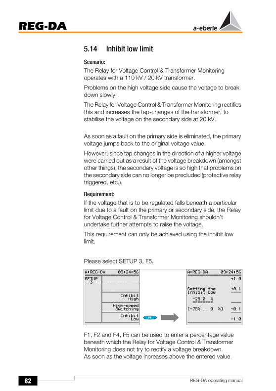
82
REG-DA
REG-DA operating manual
5.14 Inhibit low limit
Scenario:The Relay for Voltage Control & Transformer Monitoring operates with a 110 kV / 20 kV transformer.
Problems on the high voltage side cause the voltage to break down slowly.
The Relay for Voltage Control & Transformer Monitoring rectifies this and increases the tap-changes of the transformer, to stabilise the voltage on the secondary side at 20 kV.
As soon as a fault on the primary side is eliminated, the primary voltage jumps back to the original voltage value.
However, since tap changes in the direction of a higher voltage were carried out as a result of the voltage breakdown (amongst other things), the secondary voltage is so high that problems on the secondary side can no longer be precluded (protective relay triggered, etc.).
Requirement:If the voltage that is to be regulated falls beneath a particular limit due to a fault on the primary or secondary side, the Relay for Voltage Control & Transformer Monitoring shouldn’t undertake further attempts to raise the voltage.
This requirement can only be achieved using the inhibit low limit.
Please select SETUP 3, F5.
F1, F2 and F4, F5 can be used to enter a percentage value beneath which the Relay for Voltage Control & Transformer Monitoring does not try to rectify a voltage breakdown.As soon as the voltage increases above the entered value

83
REG-DA
REG-DA operating manual
again, the Relay for Voltage Control & Transformer Monitoring automatically restarts the regulation by itself.
In order to prevent short-term voltage breakdowns triggering the inhibit low of the Relay for Voltage Control & Transformer Monitoring, a time delay after which the inhibit low will be activated can be entered in SETUP 4, F5 using F1, F2, F4 or F5.
Please select SETUP 4, F5.
Example:Setpoint value 100 V
If a voltage of < 90 V occurs for a period longer than 10 seconds, the Relay for Voltage Control & Transformer Monitoring should change to inhibit low.
Input of inhibit low limit:SETUP 3, F5 Input: -10%
Time delay input:SETUP 4, F5 Input: 10 seconds

84
REG-DA
REG-DA operating manual
5.15 TriggerThe trigger limit describes the entered voltage as an absolute value, above which the Relay for Voltage Control & Transformer Monitoring suppresses all control commands.
The Relay for Voltage Control & Transformer Monitoring automatically starts regulation by itself if the voltage falls beneath this value (see also Page 242).
Please select SETUP 3, F3
Select the trigger value using the F1, F2 and F4, F5 keys and confirm the selection using the ENTER key.
Please select SETUP 4, F3
Choose the time delay for the triggering using the F1, F2 and F4, F5 keys and confirm the selection using the ENTER key.
The limit signals can also be connected to the relay outputs / binary outputs (“see "Relay assignments" on page 143).In addition, the “Trigger” signal can also be indicated by the programmable LEDs (see "LED assignments" on page 145).

85
REG-DA
REG-DA operating manual
5.16 Short description of individual limit values, setpoint values and permissible regulative deviation.
5.16.1 Description of the individual settings
Setpoint value:The value that the Relay for Voltage Control & Transformer Monitoring should regulate the voltage to.
The setpoint value can be displayed in primary or secondary values.
Secondary values: e.g. 100V or 110V
Primary values: e.g. 11 kV, 20 kV, 33 kV, 110 kV
The primary values can be displayed by parameterising the transformer mounting ratio Knu (0.01 ... 4000)
Setting range of the voltage setpoint values: 60 ... 140 V
Further information: see "Setpoints" on page 111
Tripping
Backward high-speed switching
>U
Permissible regulative deviation
<UForward high-speed switchingUndervoltage inhibit low
Tap-changes
G1
G2
G4
G3
G8
setpoint value
G6
RaiseLower

86
REG-DA
REG-DA operating manual
Permissible regulative deviation Xwz:Since the transformer mounting ratio of a tap-change transformer cannot be continuously changed, there must be a voltage range surrounding the setpoint that the Relay for Voltage Control & Transformer Monitoring cannot affect.
This range is designated as the permissible tolerance band or the permissible regulative deviation.
The lower limit of the tolerance band depends on the tap-changing increments of the transformer.
If the tolerance band is set so that it is smaller than the tap-changing increment, the Relay for Voltage Control & Transformer Monitoring “hunts” the setpoint value and repeatedly steps away from the tolerance band in both positive and negative directions.
If, on the other hand, the entered tolerance band is too large, it could lead to complaints from consumers because the voltage fluctuates over a large range.
Setting range: 0,1 ... 10%
The entered percent value always refers to the selected setpoint value.
Further information: see "Permissible regulative deviation" on page 109.
Trigger (G1):“Triggering” describes an upper absolute voltage limit, which causes the Relay for Voltage Control & Transformer Monitoring to stop carrying out tap-changes.
The limit is described on the display in plain text and if required it can also activate a relay that either triggers a protective device or simply delivers the information to the control panel.
The Relay for Voltage Control & Transformer Monitoring operates in the normal manner if the voltage is below the limit.
The setting range of the trigger is 100 ... 150 V (can only be entered as a secondary value!).
The voltage is to understood as the output voltage of the voltage transformer on the secondary side of the transformer and can only be entered as an absolute value.

87
REG-DA
REG-DA operating manual
Reason: If the “trigger” limit were based on the setpoint value (for example) and several setpoint values were used, the trigger limit would “wander” with the setpoint.
If, however, there is a fixed limit for the voltage above which the Relay for Voltage Control & Transformer Monitoring is stopped and a protective element is triggered, it is an absolute value rather than a relative value.
Further information: see "Trigger inhibit high (highest limit value of the voltage)" on page 119.
Backward high-speed switching (G2):If the voltage leaves the tolerance band, a particular time program is activated. The time program defines the amount of time that must elapse before the Relay for Voltage Control & Transformer Monitoring outputs the first (and possibly further) control commands.
All time programs are based on the assumption that large voltage deviations are rectified quickly and small deviations are rectified slowly.
The backward high-speed switching limit defines the voltage above which the time program is ignored and the transformer is regulated back to the voltage band in high-speed time by the Relay for Voltage Control & Transformer Monitoring. The voltage band is defined by the “permissible regulative deviation” parameter.
The high-speed time is defined by the running time of the transformer per switching process.
If a tap-change in operation lamp is connected, the Relay for Voltage Control & Transformer Monitoring waits until the lamp has turned off before the next tap-change occurs. If there is no tap-change in operation lamp connected, the switching frequency is determined by the maximum time TC in operation parameter (SETUP 5, F1, F2).
Setting range: 0 ... +35% *
Further information: see "High-speed switching when overvoltage occurs (LOWER)" on page 120.

88
REG-DA
REG-DA operating manual
Forward high-speed switching (G3):If the voltage leaves the tolerance band, a particular time program is activated. The time program defines the amount of time that must elapse before the Relay for Voltage Control & Transformer Monitoring outputs the first (and possibly further) control commands.
All time programs are based on the assumption that large voltage deviations are rectified quickly and small deviations are rectified slowly.
The forward high-speed switching limit defines the voltage above which the time program is ignored and the transformer is regulated back to the voltage band in high-speed time by the Relay for Voltage Control & Transformer Monitoring. The voltage band is defined by the “permissible regulative deviation” parameter.
The high-speed time is defined by the running time of the transformer per switching process.
If a tap-change in operation lamp is connected, the Relay for Voltage Control & Transformer Monitoring waits until the lamp has turned off before the next tap-change occurs. If there is no tap-change in operation lamp connected, the switching frequency is determined by the maximum time TC in operation parameter (SETUP 5, F1, F2).
Setting range: -35% ... 0% *
Further information: see "High-speed switching when undervoltage occurs (RAISE)" on page 120.
Overvoltage >U (G4):The overvoltage >U is a limit value that only influences the regulation in special operating circumstances, and that can be parameterised if required using an LED or an output relay.
If the voltage exceeds the >U limit then all “raise” commands are surpressed.
The limit value particularly influences the regulation if operating with several setpoints and using an absolute value (100 V / 110 V) as the limit value for >U.
Setting range: 0 ... +25% *

89
REG-DA
REG-DA operating manual
Further information: see "> U Overvoltage" on page 118.
Undervoltage <U (G6):The undervoltage <U is a limit value that only influences the regulation in special operating circumstances, and that can be parameterised if required using an LED or an output relay.
If the voltage falls below the <U limit, all “lower” commands are surpressed.
The limit value particularly influences the regulation if operating with several setpoints and using an absolute value (100 V / 110 V) as the limit value for <U.
Setting range: -25% ... 0% *
Further information: see "< U Undervoltage" on page 117.
Inhibit low (G8):If the voltage falls below the undervoltage inhibit low limit, the Relay for Voltage Control & Transformer Monitoring switches to a standstill.
The Relay for Voltage Control & Transformer Monitoring operates in the normal manner as long as the voltage is above the limit.
Setting range: -75% ... 0% *
Further information: see "REG-DA inhibit low when undervoltage occurs" on page 121.
* The percent values relate to the appropriate setpoint value, 100 V or 110 V.
Select the reference value in SETUP 5, Add-On 5, F2.

90
REG-DA
REG-DA operating manual

91
REG-DA
REG-DA operating manual
6 Basic Settings
The following are considered to be basic settings of the Relay for Voltage Control & Transformer Monitoring: Time, password, interfaces (COM1, COM2, E-LAN), LCD contrast, etc.
All of the basic settings can be defined and modified in “SETUP” menu 6.
6.1 General
6.1.1 Station ID
NoteRelays for Voltage Control & Transformer Monitoring which are operated on a bus (E-LAN) must have different addresses (A ... Z4).
A to Z4

92
REG-DA
REG-DA operating manual
6.1.2 Station name
NoteThe Relay name is best entered using WinREG. However, it can also be entered using the Relay keypad and the following procedure.
Õ
Õ
`
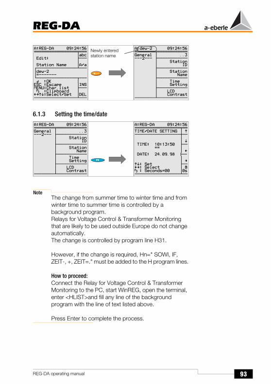
93
REG-DA
REG-DA operating manual
6.1.3 Setting the time/date
NoteThe change from summer time to winter time and from winter time to summer time is controlled by a background program.Relays for Voltage Control & Transformer Monitoring that are likely to be used outside Europe do not change automatically.The change is controlled by program line H31.
However, if the change is required, Hn=" SOWI, IF, ZEIT-, +, ZEIT=." must be added to the H program lines.
How to proceed:Connect the Relay for Voltage Control & Transformer Monitoring to the PC, start WinREG, open the terminal, enter <HLIST>and fill any line of the background program with the line of text listed above.
Press Enter to complete the process.
Õ
Newly entered station name

94
REG-DA
REG-DA operating manual
6.1.4 LCD contrast (display)The contrast setting can be used to ensure that the Relay display can be read easily from various viewing angles.
6.1.5 PasswordThe password prevents changes to individual settings. Measurement values and parameters can, however, be “read” without restrictions.
If the password is used, the locking only comes into effect approximately 4 minutes after it is applied.
NoteUser 1 may change all passwords at will, whereas all of the other users can only change their own personal password.

95
REG-DA
REG-DA operating manual
Deleting PasswordsEnter “111111”.
It is only possible to delete a password if user 1 has “opened” the device with his/her password!
NoteThis procedure switches off the entire password request (including that of other users!).The passwords of users 2 to 5 (only) are deleted.
Password request
Wrong Password
6.1.6 Deleting recorder data(resetting the measured value memory)
CorrectPasswordInsert
after confirmingwith the key
i h “R ”
the memoryof the recorderwill be deleted.

96
REG-DA
REG-DA operating manual
6.1.7 Deleting tap-change sums(resetting the tap-counter to zero)
6.1.8 Actual value correction of the measuring voltage UE
The actual value correction of the voltage is designed to compensate for voltage drops on the line and to correct measurement transformer errors.
6.1.9 Actual value correction of the measuring current IEThe actual value correction of the current primarily corrects errors in the measurement transformer.
after confirmingwith the key
i h “R ”
the total numberof tap-changesReset to zero

97
REG-DA
REG-DA operating manual
NoteIf the parameters are read out and archived via WinREG, the values of the actual value corrections will be missing, because they can only be assigned to a certain device and are not transferable to other devices!
6.2 RS-232 interfaces
6.2.1 COM 1The COM 1 interface can be used as a parameterisation / programming interface via a SUB-D plug on the front of the device.
The standard setting is “ECL”.
This mode enables WinREG to access the Relay for Voltage Control & Transformer Monitoring. Furthermore, time synchronisation can be carried out via DCF77 (with “DCF77” setting and connection of a suitable antenna).
A profibus module can be addressed in “PROFI” mode and information from the E-LAN system bus is directed to COM 1 using the LAN-L or LAN-R setting.

98
REG-DA
REG-DA operating manual
For more information, please also refer to COM 2 from Page 99 onwards.
Õ
Õ

99
REG-DA
REG-DA operating manual
6.2.2 COM 2COM 2 is also suitable for the control system connection of a REG-DA Relay for Voltage Control & Transformer Monitoring.If the REG-DA is connected to other devices (RED-D, REG-DP, REG-DPA, EOR-D, PQI-D, CPR-D, etc.) via E-LAN, it is possible to communicate with several devices via a single interface.
This possibility is not available for all profiles, therefore we advise you to contact our company headquarters.
If the COM 2 interface is used for permanent connections to higher-level systems, the COM 1 interface remains available for connecting a PC, printer or modem.
An (integrated) protocol card (see feature list XW90, XW91 or L1, L9) is also required for communication with a control system.
The data exchange between the Relay for Voltage Control & Transformer Monitoring and the protocol interface is carried out via the COM 2 interface. The integrated protocol card converts the Relay for Voltage Control & Transformer Monitoring information to the standard-compliant language according to IEC 61870-5-101, -103, -104, IEC 61850, MODBUS, SPABUS, PROFI.BUS, DNP 3.0, LON. Similarly, it translates the information from the control system into a “dialect” that the Relay for Voltage Control & Transformer Monitoring can understand.
Õ
Õ

100
REG-DA
REG-DA operating manual
The standard mode is the “MODE ECL”. The selection of the DCF77 setting and the connection of a suitable aerial should only be carried out if the time is to be synchronised via DCF77.
If the information of the E-LANs (LAN-L, LAN-R) is to be routed to the serial interface, for example to achieve modem transmissions on the “E-LAN level”, the Relay for Voltage Control & Transformer Monitoring must be set to LAN-L or LAN-R. A more detailed description has been omitted here since these types of connections should always be carried out with the support of our company.
“PROFI” is always the right setting for the COM, if a PROFIBUS-DP connection should be implemented.In this case, an external PROFIBUS-DP module is controlled via COM 1 or COM 2.
The setting ECL+HP enables output which is generated via a background program to also be output via COM 2.
Example:Based on the regulated voltage or the tap-changer position, a specific text is to be output via COM 2. In this case, ECL+HP is to be selected, since all output which is generated via a background program is normally output via COM 1.

101
REG-DA
REG-DA operating manual
6.3 E-LAN (Energy-Local Area Network)For background information on the “E-LAN”, please see Page 267 and 32.
Every Relay for Voltage Control & Transformer Monitoring has two complete E-LAN interfaces.
E-LAN LEFT defines the settings for bus left(Connection level III, Terminals 69, 70, 71 and 72 see Page 42).
E-LAN RIGHT defines the settings for bus right(Connection level III, Terminals 73, 74, 75 and 76 see Page 42).
Each one of these E-LAN interfaces also functions with either a 2-wire line or 4-wire transmission technology (RS485).
A 2-wire line is normally used, because this is the only system that allows one bus configuration with several stations on the same bus line. To do so, the integrated terminating resistor of the first and the last stations on the bus line must be switched on. (Selection: „terminated”)
Circuit board - level III
BUS-L Terminal
BUS-R Terminal
Function 2-wire 4-wire
72 76 EA+ Input and output “+”
Output “+”
71 75 EA- Input and output “-”
Output “-”
70 74 E+ No function Input “+”
69 73 E- No function Input “-”

102
REG-DA
REG-DA operating manual
If the terminating resistances are not installed (terminated) properly, reflections may occur at the ends of the lines which make it impossible to transfer the data securely.
4-wire transmission technology must be used for long transmission distances or if boosters (amplifiers for increasing the signal level over very long transmission distances must be used). The required terminating resistances will be automatically activated (the selection “terminated” is no longer required).
Õ
Õ
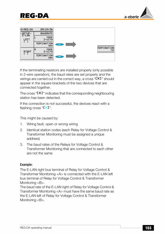
103
REG-DA
REG-DA operating manual
If the terminating resistors are installed properly (only possible in 2-wire operation), the baud rates are set properly and the wirings are carried out in the correct way, a cross “ ” should appear in the square brackets of the two devices that are connected together.
The cross “ ” indicates that the corresponding neighbouring station has been detected.
If the connection is not successful, the devices react with a flashing cross “ ”.
This might be caused by:
1. Wiring fault, open or wrong wiring
2. Identical station codes (each Relay for Voltage Control & Transformer Monitoring must be assigned a unique address)
3. The baud rates of the Relays for Voltage Control & Transformer Monitoring that are connected to each other are not the same
Example:The E-LAN right bus terminal of Relay for Voltage Control & Transformer Monitoring <A> is connected with the E-LAN left bus terminal of Relay for Voltage Control & Transformer Monitoring <B>.The baud rate of the E-LAN right of Relay for Voltage Control & Transformer Monitoring <A> must have the same baud rate as the E-LAN left of Relay for Voltage Control & Transformer Monitoring <B>.

104
REG-DA
REG-DA operating manual
4. Wrong terminationOnly the first and the last device of a bus segment may be terminated (please also refer to Page 267).
Termination is not required for a four-wire connection.
The first and last terminals only have to be terminated in a two-wire bus connection.
6.4 PAN-D voltage monitoring unit
The PAN-D monitoring unit is not equipped for entering the parameters via the screen and keypad.
If a PAN-D monitoring unit is used in connection with a REG-DA Relay for Voltage Control & Transformer Monitoring connected via E-LAN, the monitoring unit “borrows” the keypad and the screen from the Relay for Voltage Control & Transformer Monitoring for parameterising and displaying values.
Use the F4 key to start this process.
6.5 Status(current ID data of the REG-DA Relay for Voltage Control & Transformer Monitoring)
The menu item “Status” lists all of the information which is important for the system identification.
The current input status of both input circuits is displayed as a hexadecimal number in the REG-DA status (1) in addition to the firmware version and the battery status, etc..
This information is particularly useful for commissioning. The hexadecimal numbers should be interpreted as follows:
Parameterisation ofPAN - D(refer toPAN - D operating manual)

105
REG-DA
REG-DA operating manual
The input status shown above would be displayed in the status as HEX AF7D.
During the initial commissioning of the Relay for Voltage Control & Transformer Monitoring, this enables clarification as to whether or not a signal has been sent to the terminals.
Pressing the right arrow key opens a display menu in which the active additional features are listed.
In this example the ParaGramer and the four setpoint values are shown.
Inputs Inputs Inputs Inputs
16 15 14 13 12 11 10 9 8 7 6 5 4 3 2 1
Signal Signal Signal Signal
x − x − x x x x − x x x x x − x
Significance Significance Significance Significance
8 4 2 1 8 4 2 1 8 4 2 1 8 4 2 1
= HEX A = HEX F = HEX 7 = HEX D
x = ON− = OFF

106
REG-DA
REG-DA operating manual
Pressing the right arrow key again shows the COM 1 and COM 2 settings.
A further press of the right arrow key explains the settings of the E-LAN R and E-LAN L bus interfaces and provides information about the total number of stations that are registered in the network.
Pressing the right arrow key again opens a menu in which COM 3 and the stations that are detected there (ANA-D, BIN-D) are listed.
COM 3 is not connected in the example.

107
REG-DA
REG-DA operating manual
Pressing the right arrow key again displays the log book.
All important events are stored in the log together with the respective time and date. Up to 127 events can be stored in total. The LOG BOOK memory is a First In First Out (FIFO) rotating memory, i.e. if the memory is full, the oldest entry (event 1) will be replaced with the newest (127th) event.Use the keys F2 ... F5 to search for a particular entry.
The following events are saved with a time and date:
Power ONManualAutomaticLocalRemote<U<U> IForward high-speed switchingBackward high-speed switchingTriggerInhibit Low

108
REG-DA
REG-DA operating manual
7 Parameterisation of the REG-DA Relay for Voltage Control & Transformer Monitoring
The most important steps for the parameterising are also described in „Commissioning” on page 63.
The “LOCAL” and “MANUAL” operating modes must be set in order to enter parameters.
NoteChanges in the parameters are only accepted in the “MANUAL OPERATING MODE” .When the password request is activated, a valid password must be entered (for information on the password request refer to “password request” on see "Password request" on page 95).
Operating principle please refer to Page 51.
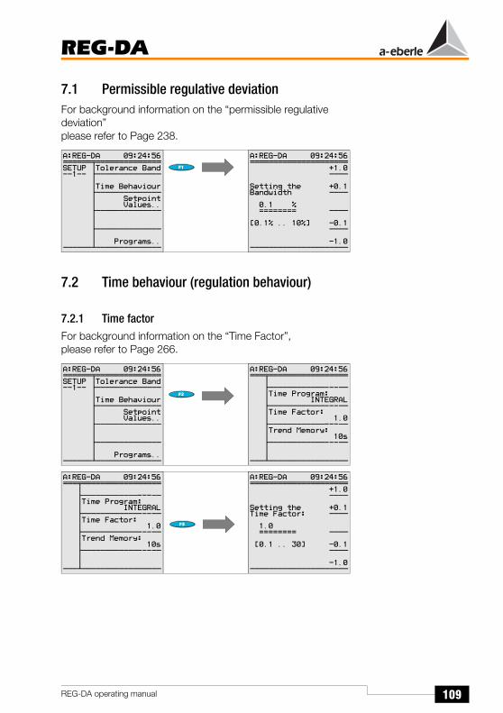
109
REG-DA
REG-DA operating manual
7.1 Permissible regulative deviationFor background information on the “permissible regulative deviation”please refer to Page 238.
7.2 Time behaviour (regulation behaviour)
7.2.1 Time factorFor background information on the “Time Factor”,please refer to Page 266.
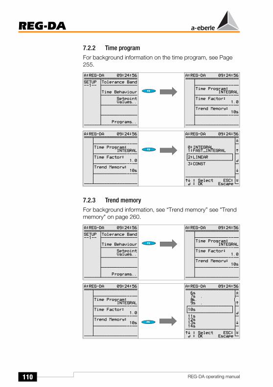
110
REG-DA
REG-DA operating manual
7.2.2 Time programFor background information on the time program, see Page 255.
7.2.3 Trend memoryFor background information, see “Trend memory” see "Trend memory" on page 260.
Õ
Õ
Õ
Õ

111
REG-DA
REG-DA operating manual
7.3 SetpointsFor background information on the “setpoint value” (command variable)please refer to Page 227.
Display of the setpoint valueIf the primary value (the single-underlined value (here: 15 kV)) should be displayed rather than the secondary value, the transformer mounting ratio Knu must be entered in the menu „Transformer configuration” on page 138.
7.3.1 1st setpoint value
The U-LL voltage always corresponds to the phase-to-phase voltage (delta voltage).
Example: The setpoint should be 100.2 V. This value should be simultaneously declared as the 100% value.
How to proceed: Using the keys F1, F2, F3 and F4 set the double-underlined value to100.2 V.Use the F3 key to set the 100.2 V valueas the 100% valueand confirm the value by pressing
“RETURN” .

112
REG-DA
REG-DA operating manual
7.3.2 Further setpoint values
Proceed in the same way for the 3rd and 4th setpoint values.
When switching from one setpoint value to another via a binary input, background program or control system, tap-changing commands will also be output at the same time until the voltage lies within the tolerance band around the new setpoint value. The time interval between two successive tap-changes is determined by the maximum time TC in operation (SETUP 5, Add-On 1).
If the regulation is carried out using the PAN-D monitoring unit, the maximum time TC in operation must always be set directly on the PAN-D when both units (REG-DA, PAN-D) are connected via E-LAN.
NoteThe REG-DA Relay for Voltage Control & Transformer Monitoring can regulate outputs (P or Q) as well as voltages. This situation will always occur if a phase-shift transformer is used. For this reason the PQCTRL feature must be loaded. Setpoint 3 will then become a P setpoint, and setpoint 4 will become a Q setpoint. The individual setpoints can be selected via the binary inputs, via the COM 1 and COM 2 interfaces or via one of the available protocols (IEC ...., DNP, MODBUS, SPABUS, etc).
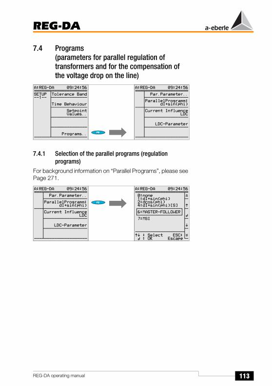
113
REG-DA
REG-DA operating manual
7.4 Programs(parameters for parallel regulation of transformers and for the compensation of the voltage drop on the line)
7.4.1 Selection of the parallel programs (regulation programs)
For background information on “Parallel Programs”, please see Page 271.
Õ
Õ

114
REG-DA
REG-DA operating manual
7.4.2 Parameters for the parallel programDifferent parameter menus are available depending on the selected parallel program.
The following menu appears for the ∆I · sinϕ (circulating current minimisation) program.
Control influence (Icirc monitoring)
For further information about setting the permissible circulating reactive current,please refer to Page 275.
Limitation
The “Limitation” menu item only appears when the ∆cosϕ program is selected.

115
REG-DA
REG-DA operating manual
Net cos ϕ
The Network cosϕ menu item only appears when the ∆cosϕ program is selected.
Nominal power of the transformer
The “nominal power of the transformer” menu item only appears when the ∆Isinϕ(S) program is selected.
Group list (of parallel-switched transformers)
The group list must be entered for all programs, except the ∆cosϕ procedure.
Relays with the same prefixes before the identification (address) are operating in parallel on one busbar.
In this example, transformers A, B and C are feeding on the same busbar.

116
REG-DA
REG-DA operating manual
7.4.3 Current influence (line-drop compensation)For background information, please see "Determining the voltage levels XR and Uf" on page 231.
The gradient and the limitation for the current influences, apparent current, active current and reactive current, are entered in Setup 1 (F1 and F2).
The parameters for the line drop compensation (LDC) are described in „LDC parameter (line drop compensation)” on page 116.
7.4.4 LDC parameter (line drop compensation)For background information, please see "Measuring the voltage drop as a function of the current strength and cos j" on page 229.
Õ
Õ

117
REG-DA
REG-DA operating manual
7.5 Gradient (U/I characteristic)For background information on the “Gradient”,please refer to Page 232.
7.6 Limitation (U/I characteristic)For background information on the “Limitation”,please refer to Page 232.
7.7 < U UndervoltageFor background information on “< U Undervoltage”,please refer to Page 244.

118
REG-DA
REG-DA operating manual
7.8 > U OvervoltageFor background information on “> U Overvoltage”,please refer to Page 243.
7.9 > I, < Limit (upper and lower current limits)For background information on “> I, < I limit value”, please refer to Page 244.

119
REG-DA
REG-DA operating manual
7.10 Triggerinhibit high (highest limit value of the voltage)
For background information on “Trigger”,please refer to Page 242.
Please note that the trigger must be entered as an absolute value.
Reason: The respective setpoint is normally used as a reference for setting the limit value.
However, if multiple setpoints are used, the trigger limit “wanders” between the selected setpoints.
In general there is only one voltage − independent of the selected setpoint − which triggers a transformer or outputs a message, thus it is always better to enter the trigger limit in V.

120
REG-DA
REG-DA operating manual
7.11 High-speed switching during undervoltage/overvoltage
7.11.1 High-speed switching when undervoltage occurs (RAISE)
For background information about high-speed forward switching,please refer to Page 243.
7.11.2 High-speed switching when overvoltage occurs (LOWER)
For background information about high-speed backwards switching,please refer to Page 242.

121
REG-DA
REG-DA operating manual
7.12 REG-DA inhibit low when undervoltage occurs
For background information on “Inhibit Low”,please refer to Page 245.
7.13 Time delays (limit signals)
NoteEach parameter or limit value can function with an individual switching delay!
7.13.1 Time delay > UFor background information on the “switching delay”,please refer to Page 241.
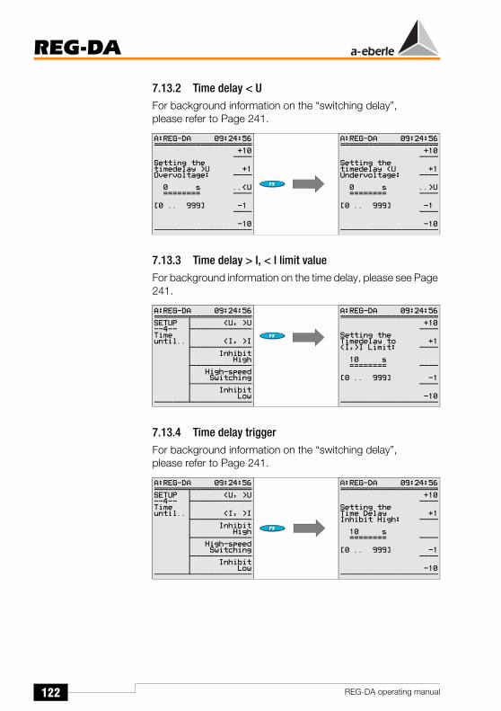
122
REG-DA
REG-DA operating manual
7.13.2 Time delay < UFor background information on the “switching delay”,please refer to Page 241.
7.13.3 Time delay > I, < I limit valueFor background information on the time delay, please see Page 241.
7.13.4 Time delay triggerFor background information on the “switching delay”,please refer to Page 241.
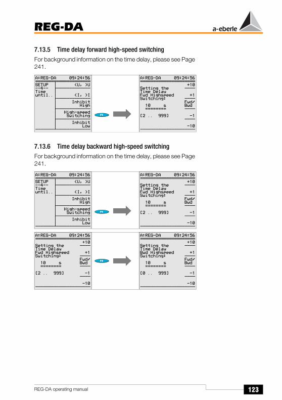
123
REG-DA
REG-DA operating manual
7.13.5 Time delay forward high-speed switchingFor background information on the time delay, please see Page 241.
7.13.6 Time delay backward high-speed switchingFor background information on the time delay, please see Page 241.
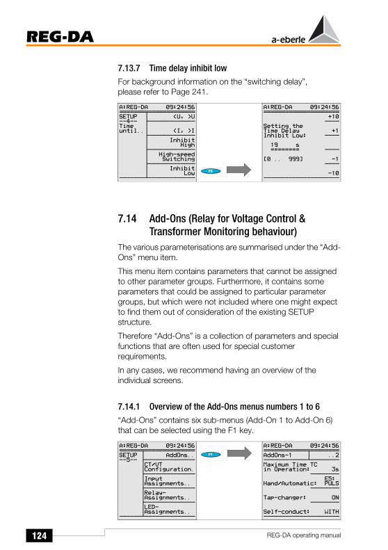
124
REG-DA
REG-DA operating manual
7.13.7 Time delay inhibit lowFor background information on the “switching delay”,please refer to Page 241.
7.14 Add-Ons (Relay for Voltage Control & Transformer Monitoring behaviour)
The various parameterisations are summarised under the “Add-Ons” menu item.
This menu item contains parameters that cannot be assigned to other parameter groups. Furthermore, it contains some parameters that could be assigned to particular parameter groups, but which were not included where one might expect to find them out of consideration of the existing SETUP structure.
Therefore “Add-Ons” is a collection of parameters and special functions that are often used for special customer requirements.
In any cases, we recommend having an overview of the individual screens.
7.14.1 Overview of the Add-Ons menus numbers 1 to 6“Add-Ons” contains six sub-menus (Add-On 1 to Add-On 6) that can be selected using the F1 key.

125
REG-DA
REG-DA operating manual

126
REG-DA
REG-DA operating manual
All the menu points are described sequentially below.The description beings with Add-On 1 and ends with Add-On 6.
7.14.2 Maximum time TC in operation (motor-drive-in operation-time)
The Relay for Voltage Control & Transformer Monitoring can be used to monitor the running time of the motor drive (tap-changer). If the set maximum time has run out, a signal will be triggered. This signal can be used to switch off the motor drive. This protects the tap-changer against passing through all cycles.
If the PAN-D voltage monitoring unit is used, the maximum time of the tap-changer in operation can only be set via the PAN-D voltage monitoring unit (refer to the PAN-D operating manual). To do this, first enter the maximum running time of the tap-changer per tap in “Add-On 1”. The maximum time TC in operation signal can then be assigned to an input (refer to input assignments (binary inputs) on see "Input assignments (binary inputs)" on page 142). Finally, the message “tap-changer interrupted” can be output via a relay output (refer to see "Relay assignments" on page 143).
There are two ways to parameterise the relay:
1. “Maximum Time of Tap-Changer in Operation-F” outputs a continuous message when the specified maximum time is exceeded.
2. “Maximum Time of Tap-Changer in Operation-F+” outputs a temporary message when the specified maximum time is exceeded.
NoteMeasure the running time of the tap-changer and enter a value for the maximum time of tap-changer in operation that is two to three seconds bigger.

127
REG-DA
REG-DA operating manual
7.14.3 Manual/Automatic
The Relay for Voltage Control & Transformer Monitoring offers two different options for switching between the Manual and AUTOMATIC operating modes.
In addition to the options already described above, the Relay for Voltage Control & Transformer Monitoring can also naturally be switched using the serial COM interfaces or the IEC-, DNP-... protocols.
If you wish to use a serial connection, it is always advisable to contact our headquarters.
Flip/Flop switching behaviourIn the “E5: PULSE“ setting, a pulse at input E5 causes a changeover from “MANUAL” to “AUTOMATIC”. A further pulse at this input causes it to change back from “AUTOMATIC” to “MANUAL”, i.e. each pulse changes the operating mode.
Bistable Switching BehaviourIn the “E5-A/E6-H” setting, a pulse or continuous signal to input E5 causes a changeover from “MANUAL” to “AUTOMATIC”. Further signals to this input do not change the operating mode, i.e. the Relay for Voltage Control & Transformer Monitoring remains in the “AUTOMATIC” operating mode.
The changeover from “AUTOMATIC” to “MANUAL” is carried out via a pulse or a continuous signal to input E6. Further signals to this input do not change the operating mode, i.e. the Relay for Voltage Control & Transformer Monitoring remains in the “MANUAL” operating mode.
Õ
Õ

128
REG-DA
REG-DA operating manual
7.14.4 Tap-changing
OFF“OFF” is selected if no signals are available for displaying the tap-changer position.
Two dashes “--” appear on the display in regulator mode.
ONIf BCD-coded signals are available for displaying the tap-changer position, please select the “ON” position.
In the regulator mode, the display shows the tap-changer position.
NoteIf an error occurs (BCD signals are present and the tap-changer parameter is set to “ON”), please check the connections and the selected “input assignment”.
If the software switch for the tap-changes is set to “ON”, yet there is no tap-change information available, the Relay for Voltage Control & Transformer Monitoring displays tap-change 0. Such a display could cause operating personnel to come to wrong conclusions.
Please also observe that the Relay for Voltage Control & Transformer Monitoring automatically checks the correctness of the tap-changer position.However, the tap-changer must be turned on.
The error message “TapErr” is displayed to indicate incorrect tap-changer settings.
TapErr is activated if an illogical tap-change is signalled.
TapErr is only intended to be informative, since the correct display of tap-changes is not essential for the regulation of individual transformers.
Õ
Õ

129
REG-DA
REG-DA operating manual
If the TapErr signal is assigned to a relay which has set the Relay for Voltage Control & Transformer Monitoring to the manual mode, regulation can be interrupted when a tap error is detected.
Further information can be found on Page 184 and Page 295.
7.14.5 Self-conduction of the operating mode
WITHWITH” stores the operating mode of the Relay for Voltage Control & Transformer Monitoring in the event that the auxiliary voltage fails. This means that after the voltage returns, the Relay for Voltage Control & Transformer Monitoring will be reset to “AUTOMATIC” if it was in “AUTOMATIC” operating mode before the voltage failure and will be reset to “MANUAL” if it was previously in “MANUAL” operating mode.
WITHOUTWITHOUT” does not store the operating mode if the auxiliary voltage fails. This means that the Relay for Voltage Control & Transformer Monitoring will always be in the “MANUAL” operating mode after the voltage returns.
7.14.6 Current display (of the transformer)

130
REG-DA
REG-DA operating manual
ONIn the “ON” setting, the current can also be displayed in the regulator display (compact display).
OFFIn order to prevent 0.000 A from being displayed for a faulty current connection, the current display can be surpressed.
7.14.7 LCD saver (display)
OnThe display turns off one hour after the keypad was last used.
However, the background illumination turns off approximately 15 minutes after the keypad was last used.
OFFThe screen always remains on; only the background illumination turns off approximately 15 minutes after the keypad was last used.
7.14.8 Regulator mode: large display
OFFThe option of choosing the detailed view will be offered on the display.

131
REG-DA
REG-DA operating manual
ONCompared to the detailed display, the large display only shows the present voltage and tap-changer position.
NoteThe F1 key can be used to switch between the normal and the large display size when in regulator mode.
7.14.9 Language selection
Õ
Õ
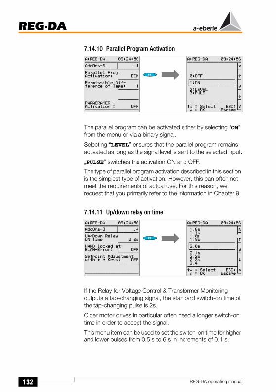
132
REG-DA
REG-DA operating manual
7.14.10 Parallel Program Activation
The parallel program can be activated either by selecting “ON” from the menu or via a binary signal.
Selecting “LEVEL” ensures that the parallel program remains activated as long as the signal level is sent to the selected input.
„PULSE” switches the activation ON and OFF.
The type of parallel program activation described in this section is the simplest type of activation. However, this can often not meet the requirements of actual use. For this reason, we request that you primarily refer to the information in Chapter 9.
7.14.11 Up/down relay on time
If the Relay for Voltage Control & Transformer Monitoring outputs a tap-changing signal, the standard switch-on time of the tap-changing pulse is 2s.
Older motor drives in particular often need a longer switch-on time in order to accept the signal.
This menu item can be used to set the switch-on time for higher and lower pulses from 0.5 s to 6 s in increments of 0.1 s.
Õ
Õ
Õ
Õ

133
REG-DA
REG-DA operating manual
7.14.12 AUTO(MATIC) LOCK in the event of an E-LAN error
If an E-LAN error is detected by the Relay for Voltage Control & Transformer Monitoring when, for example, running in parallel with multiple transformers, the respective Relay for Voltage Control & Transformer Monitoring changes from “AUTOMATIC” to “MANUAL”. However, the automatic changeover only takes place when the “AUTO lock when E-LAN fault occurs” is active. Furthermore the “AUTO lock if E-LAN fault occurs” function ensures that it is only possible to change back to “AUTOMATIC” when the fault has been rectified or when the “AUTO lock if E-LAN fault occurs” is switched from ON to OFF.
7.14.13 Setpoint adjustment
The setpoint value is normally entered via the menu.
If the setpoint value has to be changed for operational reasons,
it is possible to increase or decrease it using the left
(lower) or right (raise) arrow keys, without having to use the more lengthy corresponding SETUP method.
The percent values set in menu Add-On 3 determine the size of the increment/decrement of the setpoint value.
Õ
Õ
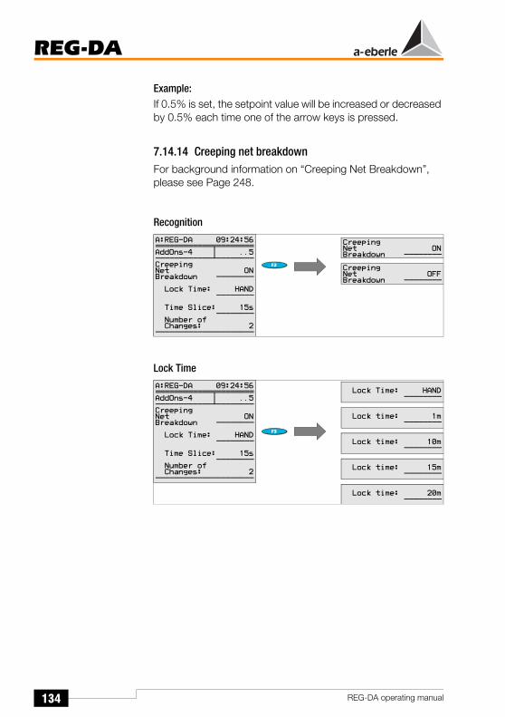
134
REG-DA
REG-DA operating manual
Example:If 0.5% is set, the setpoint value will be increased or decreased by 0.5% each time one of the arrow keys is pressed.
7.14.14 Creeping net breakdownFor background information on “Creeping Net Breakdown”, please see Page 248.
Recognition
Lock Time

135
REG-DA
REG-DA operating manual
Time Slice
Number of Changes
7.14.15 Limit base (reference value)For background information on the “limit base”, please see Page 245.
Õ
Õ

136
REG-DA
REG-DA operating manual
7.14.16 Setting the Relay for Voltage Control & Transformer Monitoring to inhibit low if <I or >I
For background information on “setting inhibit low when <I or >I”, please refer to overcurrent on Page 245.
7.14.17 Maximum tap difference (monitoring)A maximum tap-change difference may be set for the ∆Isinϕ and ∆Isinϕ(S) parallel programs. An alarm can be output during parallel switching if the difference between the transformer tap-change levels exceeds the entered maximum value. The parallel-operating group will change to MANUAL.
Please connect the Relay for Voltage Control & Transformer Monitoring so that an optical display of the situation is possible if too large a tap difference occurs.
For this purpose you can either assign the “ParErr” function to one of the freely-programmable LEDs or activate a plain text message on the Relay screen.
A background program is required for the plain text solution which can be found in our Toolbox or which can be ordered from our headquarters at any time.
The LED can be set up via SETUP 5, F5.
Please select the parameter 30: ParErr.
Õ
Õ

137
REG-DA
REG-DA operating manual
7.14.18 ParaGramer activationThe ParaGramer activation is described in detail in chapter 9.
If a system consisting of multiple transformers/Relays should be able to identify by itself which transformers are operating in parallel with which others, the ParaGramer must be switched on and the maximum number of transformers operating in parallel must be entered (ON-1 to ON-6).
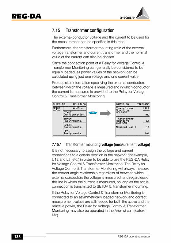
138
REG-DA
REG-DA operating manual
7.15 Transformer configurationThe external-conductor voltage and the current to be used for the measurement can be specified in this menu.
Furthermore, the transformer mounting ratio of the external voltage transformer and current transformer and the nominal value of the current can also be chosen.
Since the connection point of a Relay for Voltage Control & Transformer Monitoring can generally be considered to be equally loaded, all power values of the network can be calculated using just one voltage and one current value.
Prerequisite: information specifying the external conductors between which the voltage is measured and in which conductor the current is measured is provided to the Relay for Voltage Control & Transformer Monitoring.
7.15.1 Transformer mounting voltage (measurement voltage)It is not necessary to assign the voltage and current connections to a certain position in the network (for example, U12 and L3, etc.) in order to be able to use the REG-DA Relay for Voltage Control & Transformer Monitoring. The Relay for Voltage Control & Transformer Monitoring will always measure the correct angle relationship regardless of between which external conductors the voltage is measured, and regardless of the line in which the current is measured, so long as the actual connection is transmitted to SETUP 5, transformer mounting.
If the Relay for Voltage Control & Transformer Monitoring is connected to an asymmetrically loaded network and correct measurement values are still needed for both the active and the reactive power, the Relay for Voltage Control & Transformer Monitoring may also be operated in the Aron circuit (feature M2).

139
REG-DA
REG-DA operating manual
In order to do so, both the parameterisation (transformer mounting, voltage and current set to “ARON”) and the connection must be carried out in the correct manner.
Please observe the following connection diagram.
The following is valid for the Aron circuit:
or:
NoteEven in the Aron circuit, the Relay for Voltage Control & Transformer Monitoring only regulates the voltage connected between the terminals 2 and 5.
2 5 8 1 3 7 9
REG-DA
(A), (R), L1
(B), (S), L2
(C), (T), L3
Level I
U V W
u v w
2 5 8 1 3 7 9
REG-DA
(A), (R), L1
(B), (S), L2
(C), (T), L3
Level I
U V W
u v w
Õ
Õ

140
REG-DA
REG-DA operating manual
7.15.2 Transformer mounting ratio for the voltage
The transformer mounting ratio (Knu) of the voltage transformer must be entered if the primary voltage value is to be displayed.
Example: 20 KV/100 V Knu = 200
Please note that the scale for the input of the transformer mounting ratio can be changed, and therefore adapted to the requirements, by using the F3 key.
7.15.3 Transformer mounting current (conductor connection)
7.15.4 Transformer mounting current (conversion 1 A / 5 A)
Õ
Õ

141
REG-DA
REG-DA operating manual
7.15.5 Transformer mounting ratio for the current
The transformer mounting ratio (Kni) of the current transformer must be entered if the primary current value is to be displayed.
Example: 1000 A/100 A Kni = 1000
Please note that the scale for the input of the transformer mounting ratio can be changed, and therefore adapted to the requirements, by using the F3 key.

142
REG-DA
REG-DA operating manual
7.16 Input assignments (binary inputs)
NoteA detailed description of the individual functions can be found in Chapter 16 on Page 294.
A specific function can be assigned to each input channel from the list of selection options.
Example:If the running time of the tap-changer is to be monitored, the “tap-change in operation lamp” must be connected to an input (e.g. to input E1, as is the case on delivery).
Select “TC in operation” using the arrow keys and confirm by pressing Return. The Relay for Voltage Control & Transformer Monitoring interprets the signal at E1 as a “tap-change in operation” signal and compares it to the “maximum time TC in operation” setting in Add-On 1. Also see chapter 7.17.
If the required function is missing, the input must be set to “Prog”. The input value can then be connected according to the respective requirements via the background program.
In this case it is worth looking through the Toolbox on our website (www.a-eberle.de) for similar applications or simply contact our headquarters.
Õ
Õ

143
REG-DA
REG-DA operating manual
7.17 Relay assignments
NoteA detailed description of the individual functions can be found in Chapter 16 on Page 294.
Relays R3 ... R11 are freely programmable.A specific function can be assigned to each output from the list of selection options.
Õ
Õ

144
REG-DA
REG-DA operating manual
Example:If a message is to be sent when the running time of the tap-changer is exceeded, assign the function “TC-F” or “TC-F+” to a freely programmable relay.
If the tap-changer in operation voltage at input E1 is applied longer than was specified in “Add-on 1”, the relay R3 will be activated and can function as an indicator or actuator (motor circuit breaker off).
However, if the TC in operation lamp should be linked to one or more events, the standard functions cannot be used. A special program is required that can normally be implemented using a background program.
In order to do this the output must be set to “Prog”. The relay can then be connected and activated according to the respective requirements via the background program.
In this case it is worth looking through the Toolbox on our website (www.a-eberle.de) for similar applications or simply contact our headquarters.

145
REG-DA
REG-DA operating manual
7.18 LED assignments
NoteA detailed description of the individual functions can be found in Chapter 16 on Page 294.
LEDs 1 ... 12 are available to be freely programmed.
A specific display function may be assigned to each LED from the list of selection options.
If the exceeded of the running time of the tap-changer is to be signalled on LED 1, assign the function “TC-F” to the freely programmable LED 1.
LED 1 will be activated if the actual running time exceeds the specified running time.
If other application-specific functions are required, the LED must be set to “prog” and the function must be programmed using a background program.
To create an application-specific program, use either an example program (toolbox) from our website (www.a-eberle.de) or contact our company headquarters.
Õ
Õ

146
REG-DA
REG-DA operating manual
8 Measurement Value Simulation
In order to avoid the simulator being switched on accidentally, some operating steps are required to guarantee that the simulated voltage is only applied when it is specifically desired.
The required operating steps are:
1 Start WinREG
2 Load the terminal.
3 After pressing Enter, the device will respond by giving the respective address, e.g. <A>.
4 In step 4 you can choose between the following options:
a) Feature simmode=1(enter it like this using the terminal!) starts up the simulator, which must additionally be selected via SETUP 6, F5.In this mode, the simulator can only operate in the MANUAL operating mode.Switching from MANUAL to AUTOMATIC switches off the simulator.
b) Feature simmode=2(enter it like this using the terminal!) starts up the simulator, which must additionally be selected via SETUP 6, F5.In this mode, the simulator can also operate in the AUTOMATIC operating mode.Switching from MANUAL to AUTOMATIC does not switch off the simulator, but it does automatically change back 15 minutes after the keyboard was last used.
c) Feature simmode=0(enter it like this using the terminal!) switches off the simulator. The simulator can no longer be switched on in SETUP 6, F5.
The simulator mode (simmode=1) is activated as factory default, which only permits simulator operation in the MANUAL operating mode (simmode=1).

147
REG-DA
REG-DA operating manual
NoteIf the term “Actual Value” is displayed in capital letters as “ACTUAL VALUE”, the „MEASUREMENT VALUE SIMULATION” is active!
The simulator for the quantities U, I, and ϕ can be activated in the SETUP 6/STATUS menu.
Caution!The Relay for Voltage Control & Transformer Monitoring automatically switches back from the „MEASUREMENT VALUE SIMULATION” to normal regulation if no key has been pressed within a period of approx. 15 minutes!
NoteIf the REG-DA Relay for Voltage Control & Transformer Monitoring is operated together with the PAN-D voltage monitoring unit (connected via E-LAN), it should be observed that in simulation mode the simulated voltage will also be fed to the PAN-D. During simulation, the PAN-D only sees the simulated input voltage and not the real voltage of the system.
Õ
Õ

148
REG-DA
REG-DA operating manual
8.1 Setting the simulated voltageWhen the simulator is turned on (simmode=1 or simmode = 2) , the voltage can be simulated in regulator mode, measurement transducer mode and recorder mode using the two arrow keys
and .
The phase angle and the current can only be simulated in transducer mode.
Select “F2” in “MEASUREMENT TRANSDUCER MODE”
The right arrow key raises the simulated voltage in 0.5 V increments (when Knu=1).
The left arrow key lowers the simulated voltage in 0.5 V increments (when Knu=1).
8.2 Setting the simulated current
Select “F2” in “MEASUREMENT TRANSDUCER MODE”
”F2” increases the simulated current incrementally.
“F3” decreases the simulated current incrementally.
8.3 Setting the simulated phase angle
Select “F2” in “MEASUREMENT TRANSDUCER MODE”
”F4” increases the simulated currentin increments of 1.0 °.
”F5” increases the simulated currentin increments of 1.0 °.

149
REG-DA
REG-DA operating manual
8.4 Setting the simulated tap-changeThe tap-change position can be simulated when the simulator is switched on (simmode=1 or simmode = 2).
Start the simulated tap-change by pressing “F4” .
The simulated tap-change is indicated by
“++” after the word “measurement value simulation”.
++ Tap-change simulation is turned on
NoteThe tap-changer position can only be changed if the Relay for Voltage Control & Transformer Monitoring is set to the “MANUAL OPERATING MODE” .
“Raise arrow key” increases the simulated tap-changer position by 1 increment.
“Arrow key lower” reduces the simulatedtap-changer position by 1.

150
REG-DA
REG-DA operating manual
9 Parallel Operation of Transformers with REG-DA
Parallel switching of several transformers must be prepared in advance. In general, the taps of the transformers regulated in parallel must first be adjusted to each other and the circuit breakers and disconnectors have to be put in the corresponding position. Then, all of the Relays switched in parallel must be informed of these switching statuses.
The REG-DA Relay for Voltage Control & Transformer Monitoring is provided with a program section which is capable of independently recognizing the switching statuses of the individual transformers and can automatically group the transformers according to these switching statuses so that only those Relays feeding on one joint busbar work in parallel.
It is, of course, also possible to work in the standard way in which the parallel-switching operation is manually activated.
Both procedures require specific preparations to be carried out on the device in advance. The preparations to be carried out are described in the following sections:
Preparing manual activation
Preparing automatic activation
Before selecting the regulation procedure, please check the boundary conditions of the regulation.
Are the transformers the same or differing models? Is it possible to connect the individual Relays with each other via E-LAN, or is the distance between each feeding point too large making connection impossible?
Should the transformers be regulated so that they all have the same tap-changer position or should the circulating reactive current be minimised?
One of the regulation procedures listed below can be chosen depending on the answer:

151
REG-DA
REG-DA operating manual
All the procedures are available in the Relay for Voltage Control & Transformer Monitoring as standard.
Master-slave
Master-Slave-Independent (MSI)
∆I sinϕ (minimisation of the circulating reactive current)
∆I sinϕ (S) (minimisation of the circulating reactive current, taking into consideration the nominal powers of the transformers)
∆cosϕ
The ∆ cosϕ operation is an available regulation procedure which is always used if the Relays which are switched in parallel cannot be connected to each other via the bus (E-LAN).
If a bus error occurs during parallel operation according to the circulating reactive current minimisation procedure (∆I sin ϕ or ∆I sin ϕ (S)), the complete combination switches to an emergency regulation which also works according to the ∆cos ϕ procedure.
If a malfunction occurs, each Relay for Voltage Control & Transformer Monitoring uses the last measured cos ϕ and attempts to both maintain the voltage within the specified voltage band and to approach the last measured cosϕ as closely as possible.
Operating mode
Transformer boundary conditions Prerequisiteson the Relay
REG-DTM-REG-DA-Programs
Voltagechange per tap-change
Nominalpower
Deviationof the relative short circuit
voltages
Maximum tap-change
difference when in operation
Currentmeasurem
ent available
Tap-changing possible
Bus connectionavailable
Paralleloperation
on thebusbar
no changeno change or various
≤ 10 % None possible required requiredMaster
Slave/MSI
no change or various
no change ≤ 10 % parametisable required possible required ∆Isinϕ
no change or various
various ≤ 10 % parametisable required possible required ∆Isinϕ (S)
Paralleloperation on a network
no change or various
no change or various
no change or various
parametisable required possible possible ∆cosϕ

152
REG-DA
REG-DA operating manual
9.1 Circuit diagram (schematic)
*se
e ne
xt p
age

153
REG-DA
REG-DA operating manual
The circuit diagram shows the parallel switching of two transformers with the most important connections. The principle is the same for three transformers and more.
Please observe that the voltage and current transformers do not have to be connected in the shown manner. Every possible type of connection of the individual conductors is possible. However, it is important to ensure that the transformer configuration or switching status for carrying out measurements has been entered in SETUP 5, F2.
* Please observe the contact load at R1 and R2!
110 V DC 230 V AC20 A Switch on 5 A @ cosϕ = 1
5 A Hold 3 A @ cosϕ = 0.4
0.4 A Switch off

154
REG-DA
REG-DA operating manual
9.2 Programs for parallel operation and their prerequisites
Caution!It is particularly important to note that only REG-DA Relays for Voltage Control & Transformer Monitorings with the same firmware version can be operated in parallel.Otherwise errors can occur during operation.The current firmware version can be displayed using the Relays keypad. Please press the menu key until you havereached SETUP 6. The Relay for Voltage Control & Transformer Monitoring status page can be selected using F5.The firmware version is displayed in the first two lines, e.g. V2.01 on 01.02.04.
If different versions are installed, please download the current firmware version from our website (www.a-eberle.de or www.regsys.de) or telephone us.
9.2.1 PreparationThe following description defines both the preparations to be carried out for manual activation as well as those necessary for automatic activation of parallel switching.
For demonstrating each individual operating step, a system has been selected which consists of three transformers feeding on one busbar.
The master-slave procedure has been chosen as the parallel program.
If another program with a different number of transformers is selected, please adapt each operating step correspondingly.
In order to permit the master to check at any time whether the slaves are working correctly, it is necessary that each Relay for Voltage Control & Transformer Monitoring is supplied with the tap-change position of “its” transformer and that the bus connection (E-LAN) is activated between all the Relays.

155
REG-DA
REG-DA operating manual
9.2.1.1 Explanation of terminology
Preparing manual activation“Preparing manual activation” refers to the sequence of consecutive switching operations which prepare for the parallel operation of several transformers (adjusting the tap-change position, adding circuit breakers, disconnectors and couplings) as well as the actual manual activation of the parallel regulation.
In this case parallel regulation can be activated via the menu (SETUP 5, Add-On 6) or via a binary input signal.
Preparing for automatic activation“Preparing automatic activation” refers to the simultaneous and automatic activation of the parallel operation of several transformers as a function of the logical position (off/on) of all of the circuit breakers, disconnectors and couplings.
This type of preparation can be carried out by feeding a busbar replica (positions of the circuit breakers, disconnectors, bus ties and bus couplings) to each one of the Relays involved in the regulation.
On the basis of the switching statuses, the regulation system can automatically recognise which transformer is supposed to work with which other transformer(s) on one busbar in parallel operation.
The transformers are then regulated according to the selected regulating procedure.

156
REG-DA
REG-DA operating manual
9.2.2 Preparing manual activationThe following steps are required to set up the parallel-switching of 3 transformers according to the master-slave procedure.
If two transformers or even four transformers are required, please adapt the procedure correspondingly.
NoteIn this chapter parameterisation will be carried out using the membrane keypad of the Relay for Voltage Control & Transformer Monitoring.Of course, the individual operation steps may also be performed using the WinREG parameterisation software.
1. StepSwitch all Relays to the MANUAL mode.
2. StepAssign station identification.
The Relay for Voltage Control & Transformer Monitoring assigned to transformer 1 is given the station code (address) <A>, the Relay for Voltage Control & Transformer Monitoring assigned to transformer 2 is given the station code (address) <B>, and the Relay for Voltage Control & Transformer Monitoring assigned to transformer 3 is given the station code <C>.
Code input:
Select SETUP 6, F1, F2.
A to Z4

157
REG-DA
REG-DA operating manual
This address may be incremented using the F1 and F2 keys or decremented using the F4 and F5 keys.
Confirm your selection using <Enter>.
Each address in the range A ... Z4 is permitted, however each station code may only be assigned once.
If the PAN-D voltage monitoring unit is assigned to a REG-DA Relay for Voltage Control & Transformer Monitoring, the Relay for Voltage Control & Transformer Monitoring will automatically assign a code to its corresponding PAN-D.
To assign this address, the REG-DA Relay for Voltage Control & Transformer Monitoring increments its own address (by one!) and assigns it to the PAN-D.
Example:
If the Relay for Voltage Control & Transformer Monitoring has the code <A>, it will assign the code <A1> to the PAN-D. If the Relay for Voltage Control & Transformer Monitoring has the code <B9>, it will assign the code <C> to the PAN-D.
3. StepEstablish the connection to the bus.
To start the parallel operation, all participating Relays must be able to communicate with each other via E-LAN.
This requires that the bus link (2-conductor or 4-conductor bus) is connected in the line-to-line or standard bus structure.
Once the hardware prerequisites are fulfilled, the bus link must be parameterised [see "E-LAN (Energy-Local Area Network)" on page 101].

158
REG-DA
REG-DA operating manual
4. StepParallel program selection
Select SETUP 1, F5.
After pressing the F2 key, select the master-slave regulation procedure.
This setting is only required for the master − which usually has the address <A> − because all of the other stations will automatically be declared as slaves when the group list is input (see Step 5).
Slaves are to be assigned the parallel program “none''.
Õ
Õ

159
REG-DA
REG-DA operating manual
5. StepInput the group list
The codes of all of the Relays participating in the parallel operation are listed in the group list.
Select SETUP 1, F5, F1, F5
Please press F1, F2 and F3 to parameterise the Relays in the first, second and third positions with the codes <A>, <B> and <C> respectively.
If the group list can be entered in the manner described, then as a rule it can generally be guaranteed that the bus link will work properly.
It is not necessary to input a regulative influence for the selected procedure.
6. StepParallel switching activation
There are several different ways to activate the parallel-switching operation:
Activation via the keypad
Activation via the binary input (level-controlled)
Activation via binary input (pulse-controlled)
Activation via IEC ..., RS 232, ...

160
REG-DA
REG-DA operating manual
Activation via the keypadPlease select SETUP 5, F1, Add-On 6
Pressing down the F2 function key activates the parallel-switching operation.
Select “ON”.
Parallel operation is active in the automatic mode as long as the “Parallel Progr. Activation” is “ON”.
If you prefer to activate the parallel-switching operation via a binary input instead of via the menu, the Relay for Voltage Control & Transformer Monitoring offers two options:
The parallel operation can be activated by via a level-controlled or a pulse-controlled input.
“Level-controlled activation” means that the parallel-switching operation is activated as long as the potential is at the selected input. It will be switched off as soon as the potential at the selected input drops off.
In “pulse-controlled” activation, the parallel operation is switched on by the first pulse. The next pulse switches it off and so on.
If the parallel-switching operation is to be deactivated using a binary input, please carry out the following procedure:
Select the trigger input.
All freely programmable inputs with the exception of E5 and E6 may be used as the trigger or release input.
Õ
Õ

161
REG-DA
REG-DA operating manual
The following example demonstrates how to activate the parallel-switching operation via input E7.
Select SETUP 5, F3, F1
Press the F4 key and select the “Par Prog” function in the framed field in the middle of the display.
Accept the setting by pressing <Enter>.
The parallel-switching operation can now be activated via binary input E7.
For an optical signal that the parallel-switching operation has been activated, please select SETUP5, F5.
In the following example, the status “operating in parallel activated” is to be indicated using the freely programmable LED 4.
Õ
Õ

162
REG-DA
REG-DA operating manual
Press the F5 key and select the “Par Prog” function in the framed field in the middle of the display.
Accept the setting for LED 4 by pressing <Enter>.
If the present status of the parallel switching operation (ON/OFF) is to be fed back to the potential-free contact, please select a free relay (R3 to R11) using the F4 key in the SETUP 5 menu and also assign the Par Prog parameter to this relay.
If the parallel operation is to be activated or deactivated in a level-controlled or pulse-controlled manner, please select the preferred activation method (level or pulse) in SETUP 5, F1, Add-On 6 using the F2 key.
7. Step
Switch the circuit breakers, bus ties, bus couplings and disconnectors according to the planned parallel-switching operation.
8. Step
Switch all of the Relays to the AUTO mode.
The master first sets all of the slaves to its actual tap-changer position in order to start the voltage regulation.
In normal operation, the voltage is held within the permissible regulative deviation (bandwidth) and all transformers involved are regulated to the same tap-changer position.
Õ
Õ

163
REG-DA
REG-DA operating manual
9.2.3 Preparing automatic activationThe ParaGramer can be loaded from the start menu as a tool for preparing the automatic activation and for displaying the switching status in real time.
The artificial word ParaGramer is derived from the terms parallel and one-line diagram.
The ParaGramer displays the switching status of the individual transformers in a one-line diagram and can be loaded from the start menu using the F5 key, provided that the ParaGramer feature has been activated.
Normally up to six transformers can be operated using the ParaGramer.In a special version, however, up to 10 transformers can be connected.
The function is activated by feeding a complete busbar replica (circuit breakers, disconnectors, bus ties and bus couplings) of “its” transformer into each Relay for Voltage Control & Transformer Monitoring.The regulation system can automatically recognise which transformer is to work with which other transformer(s) on a busbar in parallel operation on the basis of the switching statuses.
Busbars that are connected via bus coupling(s) are treated as one single busbar by the system.
The standard ParaGramer version can display the following configurations:
2 transformers with one busbar(1 circuit breaker (LS) per transformer)
Note
= Switching element
= Switching element
open
closed
LS

164
REG-DA
REG-DA operating manual
3 transformers with one busbar(1 circuit breaker (CB) per transformer)
2 transformers with two busbars(1 circuit breaker (CB) and 2 isolators (IS per transformer)
3 transformers with two busbars(1 circuit breaker and 2 isolators per transformer)
CB
CB
IS

165
REG-DA
REG-DA operating manual
Busbars “1” and “2” can additionally be disconnected or coupled by means of line coupler (SC) or bar coupler (CP).
The logical status of the couplings may also be fed to the Relay for Voltage Control & Transformer Monitoring and is included in the assignment algorithm (who with whom?).
The following abbreviations have been selected to clearly characterise each individual switch, disconnector, etc.:
The prefix PG stands for ParaGramer. All of the other abbreviated terms are listed below:
PG_CB:Circuit breaker return signal of the corresponding transformer
PG_IS1:Isolator 1 return signal of the corresponding transformer to busbar 1 (the left isolator in each figure)
PG_IS2:Isolator 2 return signal of the corresponding transformer to busbar 2 (the right isolator in each figure)
PG_CP:Bus coupling return signal of the corresponding transformer
PG_SC1:Line coupler return signal right of the corresponding transformer in busbar 1
PG_SC2:Line coupler return signal right of the corresponding transformer in busbar 2
CP SC

166
REG-DA
REG-DA operating manual
1. Step
Switch all Relays to the MANUAL mode.
2. Step
Assign station identification.
The Relay for Voltage Control & Transformer Monitoring assigned to transformer 1 is given the station code (address) <A>, the Relay for Voltage Control & Transformer Monitoring assigned to transformer 2 is given the station code (address) <B>, and the Relay for Voltage Control & Transformer Monitoring assigned to transformer 3 is given the station code <C>.
Code input:
Select SETUP 6, F1, F2.
This address may be incremented using the F1 and F2 keys or decremented using the F4 and F5 keys.
Confirm your selection using <Enter>.
Each address in the range A ... Z4 is permitted, however each station code may only be assigned once.
If the PAN-D voltage monitoring unit is assigned to a REG-DA Relay for Voltage Control & Transformer Monitoring, the Relay for Voltage Control & Transformer Monitoring will automatically assign a code to its corresponding PAN-D.
To assign this address, the REG-DA Relay for Voltage Control & Transformer Monitoring increments its own address (by one!) and assigns it to the PAN-D.
A to Z4

167
REG-DA
REG-DA operating manual
Example: If the Relay for Voltage Control & Transformer Monitoring has the code <A>, it will assign the code <A1> to the PAN-D. If the Relay for Voltage Control & Transformer Monitoring has the code <B5>, it will assign the code <B6> to the PAN-D.
3. Step
Establish the connection to the bus.
To start the parallel operation, all parallel-operating Relays must be able to communicate with each other via E-LAN.
This requires that the bus link (2-conductor or 4-conductor bus) is connected in the line-to-line or standard bus structure.
The bus link must be parameterised [see "E-LAN (Energy-Local Area Network)" on page 101] once the hardware prerequisites are fulfilled.
4. Step
Activate the ParaGramer.
Please select SETUP 5, F1, Add-On 6, F5 and activate the ParaGramer by selecting the number of transformers operating in parallel.For three parallel-operating transformers select: ON-3

168
REG-DA
REG-DA operating manual
5. Step
Parameterisation of the group list.
The number of participating parallel-operating transformers (n=3) is specified by inputting the group list.
The group list is numbered consecutively and each Relay for Voltage Control & Transformer Monitoring must be parameterised in the same order. The Relay for Voltage Control & Transformer Monitoring of the first transformer must be first in the group list, the Relay for Voltage Control & Transformer Monitoring of the second transformer second in the group list, etc. The Relay for Voltage Control & Transformer Monitoring ID may be freely selected as described above. For clarity, however, the first Relay for Voltage Control & Transformer Monitoring should be assigned code A:, Relay for Voltage Control & Transformer Monitoring 2 code B:, etc.
The group list also specifies the number of transformers shown in the ParaGramer mode (2 positions in the group list occupied => 2 transformers, 3 positions occupied => 3 transformers, etc.).
The group list also indicates which Relays are presently working together:
Three symbols (+,*,=), which appear before the group list entry have been introduced to characterise the parallel-operating transformers. Relays with the same symbol are presently feeding on one busbar.
The following procedure should be carried out for each Relay for Voltage Control & Transformer Monitoring:
Setup 1
<F5> “Programs”
<F1> “Par. Parameters”
<F5> “E-LAN group list”, => Enter the stations

169
REG-DA
REG-DA operating manual
6. Step
Parallel program selection
Select SETUP 1, F5.
After pressing the F2 key, select the master-slave regulation procedure.
This setting is only required for the master - usually with the address <A>, because all of the other participants will automatically be declared as followers when the group list is input.
Slaves should be assigned the parallel program “none''.
7. Step
Input assignments
The individual programmable binary Relay for Voltage Control & Transformer Monitoring inputs are prepared for their respective tasks in this step.
Õ
Õ

170
REG-DA
REG-DA operating manual
If, for instance, the disconnector PG_TR1 of transformer 1 is to be assigned to the Relay for Voltage Control & Transformer Monitoring input E8, the function PG_TR1 must be assigned to input E 8 using menu SETUP 5, F3 “Input assignments...” and the function keys.
This same procedure applies for all of the other inputs as well.
Depending on the input assignment, the display can show one or two busbars.
The following input functions are available:
PG_CB:Circuit breaker return signal of the corresponding transformer
PG_IS1:Isolator 1 return signal of the corresponding transformer to busbar 1 (the left isolator in each figure)
PG_IS2:Isolator 2 return signal of the corresponding transformer to busbar 2 (the right isolator in each figure)
PG_CP:Bus coupling return signal of the corresponding transformer
PG_SC1:Line coupler return signal right of the corresponding transformer in busbar 1
PG_SC2:Line coupler return signal right of the corresponding transformer in busbar 2
NoteA solution is also available for applications in which the busbars are coupled crosswise.The “crosslink” feature makes it easy to master this task. This type of busbar arrangement is not described here since it is not used very frequently. If it is required, please contact our headquarters. This option is already available on your Relay for Voltage Control & Transformer Monitoring and can be activated at any time using the Firmware feature.

171
REG-DA
REG-DA operating manual
Inputs which are not in use are assigned a default setting. This makes it possible to also display system diagrams which do not correspond to the maximum possible configuration with one circuit breaker, two disconnectors, one bus coupling and two bus ties per transformer.
Summary of the default settings:
1 busbar:
PG_CB: open
PG_IS1: closed, however not displayed in theParaGramer
2 busbars:
PG_CB: closed
PG_IS1: open
PG_IS2: open
PG_CP: open
PG_SC1: closed
PG_SC2: closed
The displays to be shown are changed according to the criteria listed below:
If the Relay for Voltage Control & Transformer Monitoring in the third position in the group list is assigned a freely selected PG_xxx parameter, three transformers will be displayed in a circuit diagram instead of two.
If PG_IS2 is used on a Relay for Voltage Control & Transformer Monitoring entered in the group, two busbars will be displayed in a circuit diagram instead of one.
If either PG_CP, PG_SC1 or PG_SC2 is used on a Relay for Voltage Control & Transformer Monitoring entered in the group, the bus ties and bus couplings will be activated in the display.

172
REG-DA
REG-DA operating manual
8. Step
Displaying the busbar replica
Depending on the parameterised group list, the overview screen will display two to six relays. In addition to the ParaGramer overview, it is also possible to select a detailed display.
Selection summary:
<MENU>, <F5> => ParaGramer summary
Selecting the switching status:
<F5> Switching status/overview
Use “<” and “>” to scroll in the Switching status view.
9. Step
Switch all of the relays to the AUTO operating mode.
The parallel operation is activated automatically.
Various checks are included in order to ensure that the regulation works safely in all circumstancesThis means that the bus connection is also always monitored as well as the tap-change positon of the transformers operating in parallel.
If, for example, a tap-change position is reported that is not logical (TapErr) or a Relay for Voltage Control & Transformer Monitoring in the system cannot be addressed (ParErr), the regulation is stopped immediately and the corresponding error flag is set.
For information about TapErr and ParErr see "Description of the ParErr and TapErr error flags" on page 184.

173
REG-DA
REG-DA operating manual
9.3 Parallel operation using the “Master-Slave-Independent (MSI)” procedure
(available as of Version 2.03 from the 16th July 2004)
NoteAll of the control technology information about TapErr and ParErr also applies to the master-slave operation carried out according to any activation procedure.
MSI stands for Master (M), Slave (S) and Independent (I) operation of individual transformers.
In this operating mode, all of the participating parallel-switching transformers are placed by the operator in one of the states described above. Transformers then always work according to the principle of equalising the tap-changer positions, which is also called the master-slave procedure.
NoteThe terms master-follower and master-slave are used synonymously is everyday language and that is also the case in the following text.
Please note:
In the MSI mode, it is only possible to change the operating mode (MSI) of the Relay for Voltage Control & Transformer Monitoring when in the manual mode.
When the transformers are already operating in parallel, it is possible to switch from the AUTO mode to the MANUAL mode by switching any Relay for Voltage Control & Transformer Monitoring to the MANUAL mode.This therefore ensures that the entire group can quickly be switched to the manual mode in the event of a fault.
In the Auto mode, the group can only then be switched if the master is switched to the AUTO mode; the slaves will not accept being switched from MANUAL to AUTO.
In the independent mode, on the other hand, each Relay for Voltage Control & Transformer Monitoring can be switched back and forth from MANUAL to AUTO at any time.
The status line of the ParaGramer display indicates which Relay for Voltage Control & Transformer Monitoring is currently functioning as the master.
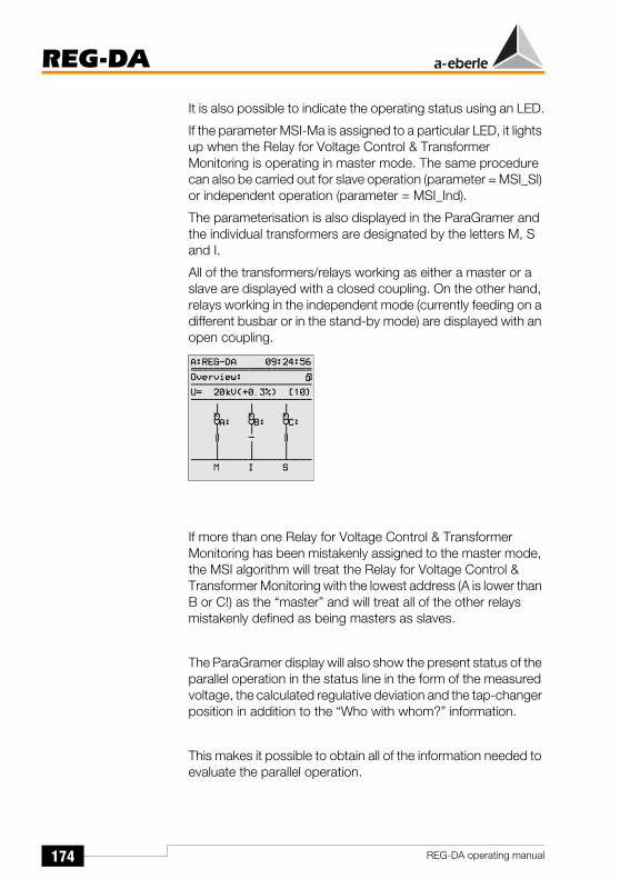
174
REG-DA
REG-DA operating manual
It is also possible to indicate the operating status using an LED.
If the parameter MSI-Ma is assigned to a particular LED, it lights up when the Relay for Voltage Control & Transformer Monitoring is operating in master mode. The same procedure can also be carried out for slave operation (parameter = MSI_Sl) or independent operation (parameter = MSI_Ind).
The parameterisation is also displayed in the ParaGramer and the individual transformers are designated by the letters M, S and I.
All of the transformers/relays working as either a master or a slave are displayed with a closed coupling. On the other hand, relays working in the independent mode (currently feeding on a different busbar or in the stand-by mode) are displayed with an open coupling.
If more than one Relay for Voltage Control & Transformer Monitoring has been mistakenly assigned to the master mode, the MSI algorithm will treat the Relay for Voltage Control & Transformer Monitoring with the lowest address (A is lower than B or C!) as the “master” and will treat all of the other relays mistakenly defined as being masters as slaves.
The ParaGramer display will also show the present status of the parallel operation in the status line in the form of the measured voltage, the calculated regulative deviation and the tap-changer position in addition to the “Who with whom?” information.
This makes it possible to obtain all of the information needed to evaluate the parallel operation.

175
REG-DA
REG-DA operating manual
Prerequisite for using the MSI operationThe MSI operating mode can only be applied when the ParaGramer feature is activated and turned on.
Relays which are delivered with the K1 feature (with parallel operation) are already parameterised in this way by default.
The ParaGramer is switched on by selecting SETUP 5, Add-On 6.
Press F5 to specify the number of transformers to be switched in parallel.
NoteAt this point it is important to state explicitly that the ParaGramer has a different function in MSI mode.It does not generate the group lists itself, but is only activated in order to make it possible to display the switching status on the regulator display.
Example: The ParaGramer must be set to ON-3 for a group of three transformers.
The MSI operating mode can be selected by choosing the MSI operating mode in SETUP 1, Programs..., Parallel Program.
Caution!The MSI operating mode must be selected for each Relay for Voltage Control & Transformer Monitoring involved in the parallel-switching operation.
We advise contacting our company headquarters if the K1 feature and, therefore, also the Paragramer, are to be enabled at a later date.

176
REG-DA
REG-DA operating manual
To verify the present settings, please selectSETUP 6, F5 (Status), --> Page 2 of the device status.
NoteSeveral features, e.g. RECORDER, TMM, etc. can, of course, be loaded at the same time.
Further prerequisites for using the MSI procedure:Only transformers which are electrically (power, short circuit voltage, voltage between the tap-changer positions, switching groups, etc.) and mechanically identical (number of tap-changer positions, position of the deadband) are suitable for MSI operation.
A different procedure should be used if one or more of the parameters differ.
In addition, it must be ensured that each Relay for Voltage Control & Transformer Monitoring receives the information regarding the tap-change position of “its” transformer.
The recording and transmission of the correct tap-change position is one of the mandatory prerequisites of the tap-change equalisation procedure.
Every potential “candidate” must be listed in the group list with its address in order to notify the system of the number of relays/transformers that should take part in parallel operation.

177
REG-DA
REG-DA operating manual
Please select the sub-menu “Parallel Parameters” inSETUP 1.
Method: SETUP 1 / Programs... (F5) / “Par. Parameters” (F1)
The group list must be set up in the “Par. Parameters“ menu.
Please select the Relay for Voltage Control & Transformer Monitoring with the lowest address by pressing the F1 key in the first group position of the list. Then place the Relay for Voltage Control & Transformer Monitoring with the next highest address in the second position in the list.
Continue in the same manner for all of the relays currently involved in the parallel-switching operation as well as for those that will be later in the parallel switching operation later.
Selecting the operating modesThree different methods can be used to select operating modes.
1. via the binary input
2. via the membrane keypad (F3 … F5)
3. via the (serial) control system
Method 1:Select three free inputs per Relay for Voltage Control & Transformer Monitoring and assign the Master (MSI_Ma), Slave (MSI_Sl) or Independent (MSI_Ind) functions to them using SETUP 5, F3 or by using WinREG.

178
REG-DA
REG-DA operating manual
Example:IT should be possible to select the operating mode using inputs E9 to E11.
The following is displayed in SETUP 5, F3:
A signal transmitted to input E-9 will cause the Relay for Voltage Control & Transformer Monitoring to work as the master.
The present status is indicated by an X in the square brackets.
The results of this parameterisation:
This status is indicated on both the regulator display as well as on the ParaGramer.

179
REG-DA
REG-DA operating manual
Method 2:Selection via the membrane keypad is only possible in the ParaGramer.
For this reason it is necessary to first return to the main menu.
Then press the F5 key to select the ParaGramer display mode.
The symbol in the status line has been assigned to the F1 key.
Press F1 and select the desired operating mode using F3, F4 and F5.
Information regarding effective manoeuvring on the screen can be found under “i” by pressing the F2 key.
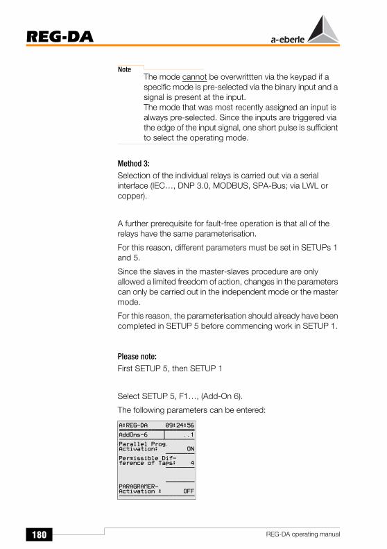
180
REG-DA
REG-DA operating manual
NoteThe mode cannot be overwrittten via the keypad if a specific mode is pre-selected via the binary input and a signal is present at the input.The mode that was most recently assigned an input is always pre-selected. Since the inputs are triggered via the edge of the input signal, one short pulse is sufficient to select the operating mode.
Method 3:Selection of the individual relays is carried out via a serial interface (IEC…, DNP 3.0, MODBUS, SPA-Bus; via LWL or copper).
A further prerequisite for fault-free operation is that all of the relays have the same parameterisation.
For this reason, different parameters must be set in SETUPs 1 and 5.
Since the slaves in the master-slaves procedure are only allowed a limited freedom of action, changes in the parameters can only be carried out in the independent mode or the master mode.
For this reason, the parameterisation should already have been completed in SETUP 5 before commencing work in SETUP 1.
Please note:First SETUP 5, then SETUP 1
Select SETUP 5, F1…, (Add-On 6).
The following parameters can be entered:

181
REG-DA
REG-DA operating manual
Explanations of the individual menu items:“Parallel Prog. activation” must be set to ON to activate parallel operation.
The indication “1st ParErr after n·tap-changer in operation time” can be interpreted as follows.
If the system is already operating in parallel with n stations, it assumes that the equalisation of the tap-change positions of all operating transformers is achieved after a maximum of 1.5 · n · the tap-changer in operation time.
If there is an error in the transmission of the BCD code or if there are problems regarding the equalisation of the tap-changer positions, a tap-changer position error (TapErr) will be detected which causes the system to stop.
However, if a transformer, which (for example) has been feeding another busbar or has been working in the stand-by mode, is selected to participate in the parallel-switching operation, this parameter can be used to specify the number of tap-changes it may deviate from the parallel transformers that are already running. This transformer is then brought to the same tap-changer position as the transformers which are already operating in parallel, one step at a time and without interrupting regulation.
If equalisation doesn’t occur within the pre-selected time, the parallel-switching is stopped and all participating relays switch to MANUAL mode.
Example:The transformer/relay <D> to be added to the parallel-switching operation is currently set to the resting position in tap-changer position 4.
The group switched in parallel is currently working in tap-changer position 8 and the motor running time between two tap-changer positions is 7 seconds.
If you want to add transformer <D> to the parallel-switched group − without considering the resulting circulating reactive currents − the “1st ParErr after n·tap-changer in operation time” parameter must be set to 4.
The monitoring algorithm of the parallel program will wait an interval of 4 times the tap-changer in operation time of the added transformer (4 x 7 seconds = 28 seconds) before a parallel error (ParErr) is triggered.

182
REG-DA
REG-DA operating manual
Under normal conditions, the new station can be “brought” to the tap-changer position of the group within this specified interval.
If this is not possible, the error flag ParErr will be set and the entire group will be switched to the MANUAL mode.
The MANUAL operating mode is the fail-safe position for all of the master-slave procedures.
The group can only be switched back to the AUTO mode via the master after the error which triggered the ParErr has been rectified.
The number of transformers/relays involved in the parallel-switching operation can be selected with the help of the “ParaGramer Activity” parameter.
Example:If three transformers/relays are to be switched in parallel,
“ParaGramer Activity” 3
must be selected by pressing F5.
Settings in SETUP 1Several settings must be carried out in Setup 1.
Under normal conditions − all of the transformers are the same − the settings for the “permissible regulative deviation” (F1), the “time factor” (F2) and the “setpoint value” (F3) should all be the same.
However, if you prefer to have different setpoint values activated when changing masters, different setpoint values can also be specified.
However, during the parallel-switching operation, only the setpoint value parameterised in the currently active master is taken into consideration.
Different setpoint values can naturally also be selected even if the setpoint values originally had the same parameterisation. To

183
REG-DA
REG-DA operating manual
do this, the setpoint value of the active master is changed via the binary input, the program or the serial interface.
Select SETUP 1, F5 (Programs).
Select the parallel program “MSI” using the F2 key.
All of the preparations necessary for the parallel-switching operation have now been carried out. Proceed in the MANUAL mode by changing the transformers until the voltage is outside of the tolerance band. Then switch to AUTO mode to verify whether the parallel-switching operation is functioning properly.
It is only functioning properly if the voltage returns to the tolerance band within a short period of time and all of the transformers are set to the same tap-changer position.
We recommend carrying out this test for both positive and negative regulative deviations.

184
REG-DA
REG-DA operating manual
9.3.1 Trouble-shootingParallel-switching operations carried out according to the MSI procedure can only function properly, if − in addition to the correct functioning of the participating Relays − the infrastructure (recording and signalling of the tap-changer position, bus connection) are also functioning fault-free.
To ensure that errors that could occur outside of the relays do not cause problems for maintaining the voltage, the two error flags ParErr and TapErr have been introduced to monitor the recording of the tap-changer position and the bus connection respectively.
9.3.1.1 Description of the ParErr and TapErr error flags A fault in the parallel-switching operation is signalled through the ParErr and TapErr error bits.
ParErrParrErr stands for a faulty parallel operation in general (parallel error) and automatically switches a group of transformers operating in parallel from the Automatic operating mode to the Manual operating mode. If a different behaviour is desired, this can be specified through an alteration to the SYSCTR feature. In this case please contact our headquarters.
ParErr is triggered, for example, when the Relay for Voltage Control & Transformer Monitoring is bypassed when a tap-changer regulation is carried out (the tap-changer position is set directly at the motor drive or via the “remote control bypass”) and the transformers are not all set back to the same tap-changer position within an interval that is 1.5 times the tap-change in operation time.
Exception: If a transformer with a specific tap difference is added to the parallel-switching operation (independent becomes slave), ParErr is not triggered until the interval specified inSETUP 5, Add-On 6, “1st ParErr after n·tap-changer in operation time” has been exceeded.

185
REG-DA
REG-DA operating manual
TapErrTapErr is a signal that indicates a problem with the tap-change position. The name is derived from the term “tap error”.
Like ParErr, TapErr affects the entire group when in MSI operating mode.
If a transformer is being switched in parallel, regulation will stop after 1.5 x the tap-changer in operation time if the tap-changer positions have not reached the same level within this time.
We recommend individually assigning the TapErr and ParErr error bits to an LED and/or a relay to inform the operating personnel about the status of the parallel regulation and to thus make it easier to rectify the error.
The following are considered to be tap errors:1. Tap-changes in the wrong direction
Example:The Relay for Voltage Control & Transformer Monitoring outputs a “raise” command and the transformer “answers” with a lower tap-change or the Relay for Voltage Control & Transformer Monitoring outputs a “lower” command and the transformer “answers” with a higher tap-change.
Possible causes of the error: The raise and lower signals have been swapped or the motor drive is behaving inversely.
Inverse behaviour implies that the Relay for Voltage Control & Transformer Monitoring increases the transformer ratio in the event of a higher tap-change, thus lowering the voltage.
In most cases, it is expected that an increase in the tap-changer position results in a higher voltage, and a decrease in the tap-changer position results in a lower voltage.
Remedy: Exchange the raise and lower signals

186
REG-DA
REG-DA operating manual
2. No tap-change
Example:The Relay for Voltage Control & Transformer Monitoring outputs a command, but the tap-changer position does not change.
In this case, it must be assumed that either the position confirmation signal or the motor drive is defective.
3. Illogical tap-changes
If no signal is received from the next higher or next lower tap position after a raise or lower command is issued, the Relay for Voltage Control & Transformer Monitoring interprets this as a fault in the tap-change operation and the TapErr flag is set.
As mentioned above, we recommend assigning the TapErr error bit to an LED and/or a relay to inform the operating personnel about the status of the parallel regulation and to thus make it easier to rectify any error.
Tap limitationIf the tap is to be limited from either above or below, please enter the following background program lines via the WinREG terminal program:
H 7=‘RegStufe-,Lower tap limitation,<=,if,RegSperreT =3,else,RegSperreT =0’
H 8=‘RegStufe-,Upper tap limitation,>=,if,RegSperreH =3,else,RegSperreH =0’
In place of the “Upper tap limitation“, enter the required upper tap limitation for your requirements and in place of the “Lower tap limitation” enter the required lower tap limitation.
NoteThe assignment of program lines H7 and H8 is arbitrary, and you can use any two program lines of your choice.

187
REG-DA
REG-DA operating manual
10 Resistance Measuring Equipment for Tap-Changers with Resistance-Coded Tap-Change Signalling
Resistance inputIf the REG-DA Relay for Voltage Control & Transformer Monitoring is equipped with a “tap-change potentiomenter” resistance input (Feature D2 or D3), the tap-changer resistance network can be connected directly and interpreted as a tap-change by the Relay for Voltage Control & Transformer Monitoring.
This eliminates the complication of using an external resistance measurement transducer.
The resistance chain receives a direct current from the Relay for Voltage Control & Transformer Monitoring via two terminals.
The voltage drop that occurs with the tap-change level is measured using further terminals.
The Relay for Voltage Control & Transformer Monitoring is normally connected in a 3-conductor circuit. Please contact our company headquarters if a 4-conductor circuit is required.
The resistance measurement equipment consists of a programmable current source to feed the measurement resistor, and a voltage measurement device to measure the voltage at the resistor. Tap-change resistances between 1 Ω and 400 Ω can be measured. However, the total resistance must remain ≤ 20 kΩ
The measurement result is output with a 12 bit resolution at a refresh rate of approx 10 Hz (0.1 s).
The measurement device has a broken-wire detection system.
The parameters are input in an application menu using the keypad.
Loading the application menuThe application menu appears when the enter key is pressed 1 to 6 times in one of the main menus (regulator measurement transducer, recorder etc.).

188
REG-DA
REG-DA operating manual
Meaning of the lines in the menu
1. Line: dR is the nominal resistance between two levels
2. Line: is the highest measurable level
3. Line: is the lowest measurable level
10.1 Error detectionThe error detection recognises the following errors:
Interruption in the current loop
Overloading of the current source
Interruption of one or both of the feeder cables for the voltage measurement input
Measurement input overloaded
Measurement range overshot
The resistance measurement value will be > RMAX for all detectable faults.
Therefore RMAX should be measured so that the value is never exceeded under normal conditions.
If an error occurs, an Infobox will be shown, which indicates the error and the present measured resistance value.
10.2 Level detectionThe level resistance value RS is a required input value.
The internal level N is calculated from the measured resistance value RM using
and displayed.
)5.0( +=S
M
RRcomponentIntegerN

189
REG-DA
REG-DA operating manual
The present measurement resistance value and the deviation, ∆Rn, of the present measurement resistance value from the present level N as a percent of RS
(-50% ... 0 ... +50%) is shown in line 5 of the application menu.
10.3 Pin assignment
3-conductor circuit
Switch S1 is in the ON position of the positive pole of the current source (IK+) and is connected to the non-inverted voltage measurement input (UE+) for the 3-conductor circuit.
the current/measurement input to connection a of the measurement resistance can therefore be connected to terminal 23 or 24.
To prevent confusion, terminal 23 is always labelled in the terminal and circuit diagrams.
Connection / switch
Description 3-conductor circuit(please also see "Connection options" on page 190)
23 IK+: Positive pole current source
Current cable to connection aof the measurement resistance
25 UE-: inv. measurement input
Measurement cable to connection bof the measurement resistance
26 IK-: Negative pole current source
Current cable to connection bof the measurement resistance
S:1.2 DIP switch Both switches in ON position
∆Rn 100%RMRS-------⎝⎛ 1-N )+⋅=

190
REG-DA
REG-DA operating manual
4-conductor circuit
10.4 Connection options
Connection / switch
Description 4-conductor circuit
23 IK+:Positive pole current source
Current cable to connection aof the measurement resistance
24 UE+:non-inv. Measurement input
Measurement cable to connection aof the measurement resistance
25 UE-:inv. measurement input
Measurement cable to connection bof the measurement resistance
26 IK-:Negative pole current source
Current cable to connection bof the measurement resistance
S:1.2 DIP switch Both switches in OFF position
) * + ,
"-
"
. ! / 0 /
"
0 1 . ! 1
) * + ,
) 1 2 & ' * 1 2 & '
3 " 4
"
-
. ! / 0 /
"
0 1 . ! 1
"
3-conductor circuit 4-conductor circuit3-conductor circuit
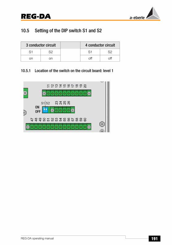
191
REG-DA
REG-DA operating manual
10.5 Setting of the DIP switch S1 and S2
10.5.1 Location of the switch on the circuit board: level 1
3 conductor circuit 4 conductor circuit
S1 S2 S1 S2
on on off off
ONOFF

192
REG-DA
REG-DA operating manual
11 mA-Inputs, mA-Outputs
The REG-D and REG-DA Relays for Voltage Control & Transformer Monitoring differ from one another in terms of design and the basic configuration of the analogue inputs.
The REG-D Relay for Voltage Control & Transformer Monitoring is not provided with any analogue inputs, whereas the REG-DA Relay for Voltage Control & Transformer Monitoring is always equipped with one analogue input module.
Both relays can optionally be upgraded with various additional modules.
The following modules are available:
Analogue input module with two mA inputs
Analogue module with only one mA input(only possible for the RG-DA)
Analogue module with only one mA output(only possible for the RG-DA)
Analogue output module with two mA outputs
PT100 module to connect a PT100 directly to a 3-conductor circuit
Resistance module as a tap-change potentiometer(1 ... 400 Ω/tap-change)(see chapter 10 for description)
The parameterisation of the inputs and outputs is the same for both types of Relay for Voltage Control & Transformer Monitoring and can be carried out using either the keypad or the WinREG parameterisation software.
It is advantageous to carry out the parameterisation using WinREG, since that is the simplest method to gain an overview of all the various parameters.
However, parameterisation using the keypad is shown in the example, since this gives an insight into the multiple possibilities.

193
REG-DA
REG-DA operating manual
11.1 Analogue inputsThe individual steps are explained using an example.
Example:In this example parameterisation is carried out on a REG-DA, which is equipped with one mA input (Channel 1) as standard.
The tap-change of a transformer is delivered using a mA signal and is connected to channel 1 of the Relay for Voltage Control & Transformer Monitoring.
The mA signal between 4 ... 20mA should represent a tap-change range of 1 to 17 tap-change positions.
How to proceed:
Assuming that you are in one of the display menus (regulator, measurement transducer, etc.), select menu and then select SETUP 6 using the arrow keys.
Press F1 to select General 1.
The submenus which are required for parameterising the analogue channels can then be reached by pressing F5.
Press F5 ANALOGUE..

194
REG-DA
REG-DA operating manual
Up to 6 analogue channels can be selected using the arrow keys (raise, lower).
The REG-D Relay for Voltage Control & Transformer Monitoring can be equipped with up to six channels, whereas the REG-DA Relay for Voltage Control & Transformer Monitoring can only have a maximum of 4 analogue channels.
This statement is only true if no further analogue channels are equipped using level II.
Up to 8 analogue channels can be contained on level II in the maximum design.
The entry “channel 1 AI/ANA” (AI analogue input) and, for example, “channel 3 AO/ANA” (AO analogue output) is created automatically and shows that channel 1 is prepared as an analogue input and that channel 3 is hardware-prepared as an analogue output.
Select channel 1 (F2)
This is ASETUP 1, in which various characteristic quantities of the input can be parameterised.
The analogue function can be selected using the F2 key.
Õ
Õ

195
REG-DA
REG-DA operating manual
The following functions are available as standard:
Notean “i” at the beginning of a line stands for input!
OFF Input is turned off
ANA Input is assigned a specific function using abackground program
iOilTp-TR input: represents the oil temperature of thetransformer
iOilTp-TC input: represents the oil temperature of thetap-changer
iOilL-TR input: represents the oil levelof the transformer
iOilL-TC input: represents the oil level of the tap-changer
iWater input: represents the hydrogen content(H2) in the oil
iGas input: represents the amount of dissolved gases in the oil
iTapPos input: represents the tap-change position of thetransformer
NoteThe quantities OilTp-TR and OilTp-TC must be supplied using the PT100 module. The oil level, water and gas measurement quantities can also only be handled if they are available as mA signals from an appropriate sensor.
Select “iTapPos” using the F2 and F4 arrow keys and then confirm the selection by pressing Enter.
Õ
Õ

196
REG-DA
REG-DA operating manual
Choose “Pos.” for position as the analogue unit
Press F3
The available character sets can be shown by pressing “abc” (F1 key).
Select the appropriate letters using the arrow keys (up, down, left, right) and confirm the selection by pressing Enter.
You can switch between upper and lower case by pressing F2.
F4 and F5 insert and delete a character respectively.
Decimal places are not required in this case since the tap-change position is a whole-number quantity.
Press F4 and then reduce the number of decimal places to zero by pressing F4 again.
Õ
Õ

197
REG-DA
REG-DA operating manual
Confirm your selection by pressing Enter.
The type of characteristic line can be selected under the “parameter selection” menu item.
The following settings are possible:
ALL Only for special applicationsrelated to old software versions.
Fac+Off Only for special applicationsrelated to old software versions.
P0P2 Linear characteristic line
P0P1P2 Bent characteristic line
P0P2 (linear characteristic line)A linear characteristic line has two coordinates (beginning and end) which can be described using the points P0 and P2.
Each point is specified using an x coordinate and a y coordinate.
The characteristic lines are so constructed that mA values (input or output) are always placed on the y axis in normalised form.
The upper limit of the mA input or output is always determined by the specific hardware configuration. Therefore a normalised representation is sensible.
Example:
0 ... 20 mA is displayed as Y0 = 0 and Y2 = 1
4 ... 20 mA is displayed as Y0 = 0.2 and Y2 = 1
0 ... 5 mA is displayed as Y0 = 0 and Y2 = 1
0 ... 10 V is displayed as Y0 = 0 and Y2 = 1

198
REG-DA
REG-DA operating manual
P0P1P2 (bent characteristic line)
Bent characteristic lines can also be displayed.
In this case, the point P1 must be entered, which is defined as lying between points P0 and P2.
y
x
P0
P2
P0-y
P2-y
P0-x P2-x
y
x
P0
P2
P0-y
P2-y
P0-x P2-x
P1P1-y
P1-x

199
REG-DA
REG-DA operating manual
A bent characteristic line is selected for the following tasks.
Select “P0P2” using F2 or F4 and confirm the selection by pressing Enter.
Proceed to the next menu, ASETUP2, by pressing the right arrow key.
The coordinates for the characteristic line are input in this menu.
The characteristic line points P0 and P2 are defined via coordinate pairs P0-X (output quantity at start of the line), P0-Y (input quantities at the start of the line)P2-X (output quantity at the start of the line) and P2-Y (input quantity at the end of the line).
Õ
Õ
Õ

200
REG-DA
REG-DA operating manual
Proceed to the next menu, ASETUP3, by pressing the right arrow key.
This SETUP defines how the analogue input should behave if the region boundaries are exceeded.
The following choices are available under “Limit Handling”
None
High
Low
High+Low
y
x/tap-ch
P0
P2
P0-y (0.2)
P2-y (1)
1 17P0-x P2-x
Õ
201
REG-DA
REG-DA operating manual
Explanations:None: no limiting,
neither up nor down
High: Limiting, upwards onlyPractical meaning:In the selected example, the Relay for VoltageControl & Transformer Monitoringwould display tap-change position 17, if theupstream measurement transducer over-controls and outputs,for example, 24mA instead of 20mA.
Low: Limiting, downwards onlyPractical meaning: In the selected example, the Relay for VoltageControl & Transformer Monitoringwould display tap-change position 1, if theupstream measurement transduceroutputs only 0mA instead of 4mA.
Recommendation:In the case of inputs 4 ... 20mA, the lower limit should not be activated, otherwiseimportant information may be lost.
If the input signalvalue falls below 4 mA, the display remains at tap-change position 1.If the limiting is notactive, the Relay for Voltage Control &Transformer Monitoring displays tap-change position 99, which could easily be mis-interpreted as an error signal.
High + Low: Limits both upwards and downwardsPractical meaning: see above
One can decide individually in each case if thelimiting function is helpful or not. A general recommendation cantherefore not be given for this reason.

202
REG-DA
REG-DA operating manual
The menu item “Input resolution” is only for information purposes. It displays the resolution with which the input signal is further internally processed.
In this case 0.05%.
You can return to the ANALOGUE I/O menu by pressing the Esc key.
If the left arrow key is pressed in this menu, the actual input and output values of the analogue values are displayed.
AnaR 1 then displays the actual value 20 mA if 20 mA is flowing in the input.
(AnaR 1= 20 mA).
Pressing the left arrow key again displays the normalised value of the input quantity.
If 20 mA hardware is being used, then the normalised value AnaN 1 = 1 if 20 mA is flowing, and AnaN 1 = 0.2 if only 4 mA is flowing.

203
REG-DA
REG-DA operating manual
11.2 Analogue outputs
For general information about the analogue channels, see Page 192.
The individual steps are explained using an example.
Task: The tap-change position of the Relay for Voltage Control & Transformer Monitoring should be output as a mA signal.
i.e. Tap-change positions 0 to 17 4 ... 20 mA
How to proceed:
The Relay for Voltage Control & Transformer Monitoring must be equipped with an analogue output module (in the example with a double module for channels 3 and 4).
Assuming that you are in one of the display menus (regulator, transducer, etc.), select menu and then select SETUP 6 using the arrow keys.
Press F1 to select General 1.

204
REG-DA
REG-DA operating manual
The submenus which are required for parameterising the analogue channels can then be reached by pressing F5.
Up to 6 analogue channels can be selected using the arrow keys (raise, lower).
The REG-D Relay for Voltage Control & Transformer Monitoring can be equipped with up to six channels, whereas the REG-DA Relay for Voltage Control & Transformer Monitoring can only have a maximum of 4 analogue channels.
This statement is only true if no further analogue channels are equipped using level II.Up to 8 analogue channels can be contained on level II in the maximum design.
The entry “channel 1 AI/ANA” (AI analogue input) and “channel X AO/ANA” (AO analogue output) is created automatically and shows that channel 1 has an analogue input (AI) and that channel 3 and 4, for example, is hardware-prepared as an analogue output (AO).
Select channel 3 (F4)
This is ASETUP1 in which the analogue function, analogue units, decimal places and the parameter selection can be entered.
Õ
Õ

205
REG-DA
REG-DA operating manual
The analogue function can be selected using the F2 key.
The following functions are available as standard:
Note„o” at the beginning of the line stands for output !
OFF Output is turned off
ANA Output is assigned a specific function using abackground program
oZero “0” is output
o+FullRng The upper limit is output (e.g. 20 mA)
o-FullRng The starting value is output(e.g. -20 mA)
NoteThe three functions can be used to check the output type (e.g. 20 mA output or 10 mA output) and its function.
oU The measured voltageis displayed as an output
oP The measured active poweris displayed as an output
oQ The measured reactive poweris displayed as an output
oS The measured apparent poweris displayed as an output
oU1 The measured voltage U1is displayed as an output
oU2 The measured voltage U2is displayed as an output

206
REG-DA
REG-DA operating manual
NoteThe following applies for the REG-DA Relay for Voltage Control & Transformer Monitoring:U1: Voltage between terminals 2 and 5U2: Voltage between terminals 8 and 10
Whereas for the REG-D Relay for Voltage Control & Transformer Monitoring the following applies:
The connection points for U1 and U2 can be found in the planning documents (see appendix).
ol1 The measured current in conductor 1is displayed as an output
ol2 The measured current in conductor 2is displayed as an output
ol3 The measured current in conductor 3is displayed as an output
oPHIDEG The measured phase angle phiis displayed as an output
oOCOSPHI The measured cos phiis displayed as an output
oFREQ The measured frequencyis displayed as an output
oOilTemp The measured oil temperatureis displayed as an output
oWindTemp the calculated hotpoint temperatureis displayed as an output
oTapPos The present tap-change position of thetransformer is displayed as an output
Please select oTapPos as an analogue function.
Confirm your selection by pressing Enter.
Õ
Õ

207
REG-DA
REG-DA operating manual
Analogue unit:
In this case and in most other cases, the analogue unit is fixed, i.e. the system automatically applies the correct unit (“V” for voltage, “A” for current and “Hz” for frequency).
However, the unit can be freely selected if ANA is selected.
In such cases, please proceed as described below:
Press F3
The available character sets can be shown by pressing “abc” (F1 key).
Select the appropriate letters using the arrow keys (up, down, left, right) and confirm the selection by pressing Enter.
You can switch between upper and lower case by pressing F2.
F4 and F5 insert and delete a character respectively.
Õ
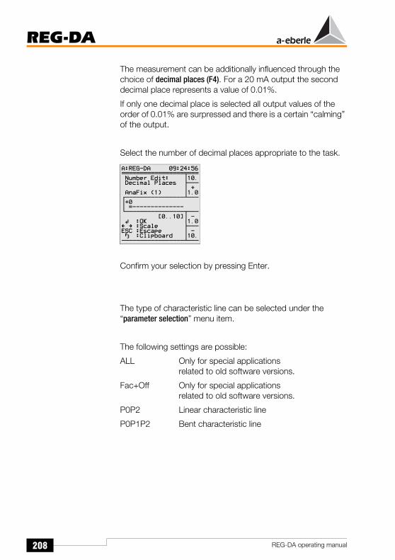
208
REG-DA
REG-DA operating manual
The measurement can be additionally influenced through the choice of decimal places (F4). For a 20 mA output the second decimal place represents a value of 0.01%.
If only one decimal place is selected all output values of the order of 0.01% are surpressed and there is a certain “calming” of the output.
Select the number of decimal places appropriate to the task.
Confirm your selection by pressing Enter.
The type of characteristic line can be selected under the “parameter selection” menu item.
The following settings are possible:
ALL Only for special applicationsrelated to old software versions.
Fac+Off Only for special applicationsrelated to old software versions.
P0P2 Linear characteristic line
P0P1P2 Bent characteristic line
Õ

209
REG-DA
REG-DA operating manual
P0P2A linear characteristic line has two points (beginning and end) which can be described using the points P0 and P2.
Each point is specified using an x coordinate and a y coordinate.
The characteristic lines are constructed in such a way that mA values (input or output) are always placed on the y axis in normalised form.
The upper limit of the mA input or output is always determined by the specific hardware configuration.
Therefore a normalised representation is sensible.
Example:
0 ... 20 mA is displayed as Y0 = 0 and Y2 = 1
4 ... 20 mA is displayed as Y0 = 0.2 and Y2 = 1
0 ... 5 mA is displayed as Y0 = 0 and Y2 = 1
0 ... 10 V is displayed as Y0 = 0 and Y2 = 1
y
x
P0
P2
P0-y
P2-y
P0-x P2-x

210
REG-DA
REG-DA operating manual
P0P1P2Bent characteristic lines can also be displayed.
In this case, the point P1 must be entered, which is defined as lying between points P0 and P2.
A bent characteristic line is selected for the following tasks.
Select “P0P2” using F2 or F4 and confirm the selection by pressing Enter.
Proceed to the next menu, ASETUP2, by pressing the right arrow key.
y
x
P0
P2
P0-y
P2-y
P0-x P2-x
P1P1-y
P1-x
Õ
Õ
Õ

211
REG-DA
REG-DA operating manual
The coordinates for the characteristic line are input in this menu.
The characteristic line points P0 and P2 are defined via coordinate pairs P0-X (input quantity at start of the line), P0-Y (output quantity at the start of the line)P2-X (input quantity at the end of the line) and P2-Y (output quantity at the end of the line).
Select the following characteristic line parameters using F2 to F5:
P0-X 1 (for tap-change position 1)
P0-Y 0.2 (0.2 x 20 mA = 4 mA) as a normalised value of the 20 mA outputvalue.
P2-X 17 (for tap-change position 17)
P2-Y 1 (1 x 20 mA = 20 mA) as a normalised value of the 20 mA outputvalue.
Confirm all input information by pressing Enter!
y
x/tap-ch
P0
P2
P0-y (0.2)
P2-y (1)
1 17P0-x P2-x

212
REG-DA
REG-DA operating manual
Proceed to the next menu, ASETUP3, by pressing the right arrow key.
This SETUP primarily defines how the analogue input should behave if the range limits are exceeded.
The following options are available under “Limit Handling”:
None
High
Low
High+Low
Explanations:
None: no limiting, neither up nor down
High: Limiting, upwards onlyPractical meaning: In the selected example, the Relay for VoltageControl & Transformer Monitoringwould output 20 mA if thetransformer is in tap-change position 20.
Low: Limiting, downwards onlyPractical meaning: In the selected example, the Relay for VoltageControl & Transformer Monitoringwill output 4 mA if the level has avalue smaller than 1
High + Low Limits upwards and downwardsPractical meaning: see above
Õ
213
REG-DA
REG-DA operating manual
The built-in simulator can be used to check the settings (see chapter 8).
Simulate a tap-change (see chapter 8.4 on Page 149).
Select SETUP 6, F1, F5 again. The ANALOGUE I/O [1-4] menu will appear in the display.
If the left arrow key is pressed in this menu, the actual output value of the analogue value will be displayed.
Assuming that tap-change position 17 has been simulated, AnaR 3 delivers an output of 20 mA that can be checked using a mA meter.
Pressing the left arrow key again displays the normalised value of the output quantity.
If 20 mA hardware is being used, the normalised value AnaN 1 = 1 if 20 mA is flowing, and AnaN 1 = 0.2 if only 4 mA is flowing (level 1).
The parameterisation has now been completed.
Press the ESC key twice to return to the regulator, transducer, recorder, etc. in the main menu.

214
REG-DA
REG-DA operating manual
12 Updating the Operating Software
A zero modem cable is required to update the operating software. A hardware handshake is required due to the high baud rate (link the RTS/CTS lines crosswise).
9-pole Sub-D socket 9-pole Sub-D socket1 ---------- ----------- ---------- 42 ---------- ----------- ---------- 33 ---------- ----------- ---------- 24 ---------- ----------- ---------- 15 ---------- ----------- ---------- 56 ---------- ----------- ---------- 67 ---------- ----------- ---------- 88 ---------- ----------- ---------- 79 ---------- ----------- ---------- 9
Shield ----------- Shield
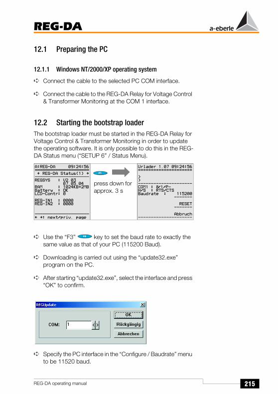
215
REG-DA
REG-DA operating manual
12.1 Preparing the PC
12.1.1 Windows NT/2000/XP operating system
Connect the cable to the selected PC COM interface.
Connect the cable to the REG-DA Relay for Voltage Control & Transformer Monitoring at the COM 1 interface.
12.2 Starting the bootstrap loaderThe bootstrap loader must be started in the REG-DA Relay for Voltage Control & Transformer Monitoring in order to update the operating software. It is only possible to do this in the REG-DA Status menu (“SETUP 6” / Status Menu).
Use the “F3” key to set the baud rate to exactly the same value as that of your PC (115200 Baud).
Downloading is carried out using the “update32.exe” program on the PC.
After starting “update32.exe”, select the interface and press “OK” to confirm.
Specify the PC interface in the “Configure / Baudrate” menu to be 11520 baud.
press down for approx. 3 s

216
REG-DA
REG-DA operating manual
Caution!If a version of the bootstrap loader older than 1.07 (e.g. 1.06) is installed on your REG-DA, it must first be updated to version 1.07. The current bootstrap loader is available to be downloaded from our website (www.a-eberle.de). Select the menu item “Update / new bootstrap loader” to begin the bootstrap loader update. The firmware can be updated after successfully updating the bootstrap loader.
The firmware update can be started by selecting the “Update / update all” menu item. Ensure that no old bootstrap loader version is located in the firmware directory, or carry out the update of the firmware and help texts individually.
Other items in the update menu:

217
REG-DA
REG-DA operating manual
Firmware: Update the firmware without the help text.
Help text: Update the help text.
REG-L Download: TransferBackground programsfrom the PC to the REG-D/DA.
REG-L Upload: Transfer and savingof the background programs fromthe PC to the REG-D. Serves to protect the backgroundprograms, since they during thereading of the parameters withWinREG not protected
Communication Card Update: Data transfer from the PC to the
instrumentation and control card
In newer devices, the program automatically recognises whether a REG-D/DA or a PAN-D is connected.If recognition is not possible (this could be the case with older devices), selection is carried out via a dialogue.

218
REG-DA
REG-DA operating manual
Select the new firmware file.
Select the new help file.

219
REG-DA
REG-DA operating manual
Information about starting the download is then dispayed.
The further process runs automatically. A reset occurs after completion of the download. A message appears to indicate that the device is ready for use.
If other messages appear, an error has occured and the download must be repeated.
NoteIf you have further questions, please send us an e-mail: “[email protected]”
Press “F4” to exit the bootstrap loader.
Press “F5” to abort the data transfer

220
REG-DA
REG-DA operating manual
13 Maintenance and Current Consumption
13.1 Cleaning informationThe surface of the device can be cleaned witha dry cloth at any time.
If the inside becomes dirty due to improper use, it is recommended that you send the device back to the manufacturer.
If a large amount of dust has accumulated on the terminal blocks, the insulator coordination could fail.
Dust particles are generally hygroscopic and can bridge creepage distances.
For this reason we recommend operating the device with the doors closed. Furthermore, in dusty environments it is particularly important to ensure that the cable connections are correctly mounted.

221
REG-DA
REG-DA operating manual
13.2 Changíng fuses
Caution!It is essential that the REG-DA Relay for Voltage Control & Transformer Monitoring is disconnected from the power supply before changing fuses!
Required fuse: T2L 250 V, 2 A microfuse
A replacement fuse can be found in the plastic container at the bottom of the housing.
13.3 Changing the battery
Caution!Before changing the battery it is essential that the REG-DA Relay for Voltage Control & Transformer Monitoringis disconnected from the power supply!
Required battery: Lithium 3 V with soldering tagsType SANYO CR 14250 SE (3 V)
Service life: in storage > 6 years
when in operation with a switch-on duration > 50 %
> 10 years
We recommend having the battery changed in the factory.
Fuse
Replacementfuse

222
REG-DA
REG-DA operating manual
If for certain reasons this is not possible, the following precautionary measures should be carried out: all the parameters should be saved using WinREG, the recorder should be read out and the log book and the statistics unit should be backed up.
Firstly the four fixing screws of the membrane keypad should be undone using a cross-head screwdriver. Then carefully fold the membrane keypad to the left.
The battery holder should then be removed and the connection plug should be unplugged.
The new battery can now be inserted and the device can be closed again. The steps listed above should then be carried out in the reverse order.
Battery

223
REG-DA
REG-DA operating manual
13.4 REG-DA Current Consumption
Measuring circuit (100 V DC)
Measurement results
The measured values provide information regarding the fuse selection.
REG-DA30
28
1 Ω / 1%
Sensor head10:1220µF
100 V
0 ... 150 V300 mA
7 ms
3 V= 3 A
Power-up spike of 100 V DC
6
5
4
3
2
1
Measured at Peak60 V DC approx. 2 A110 V DC approx. 3 A
110 V AC approx. 3 A220 V DC approx. 5 A230 V AC approx. 5 A
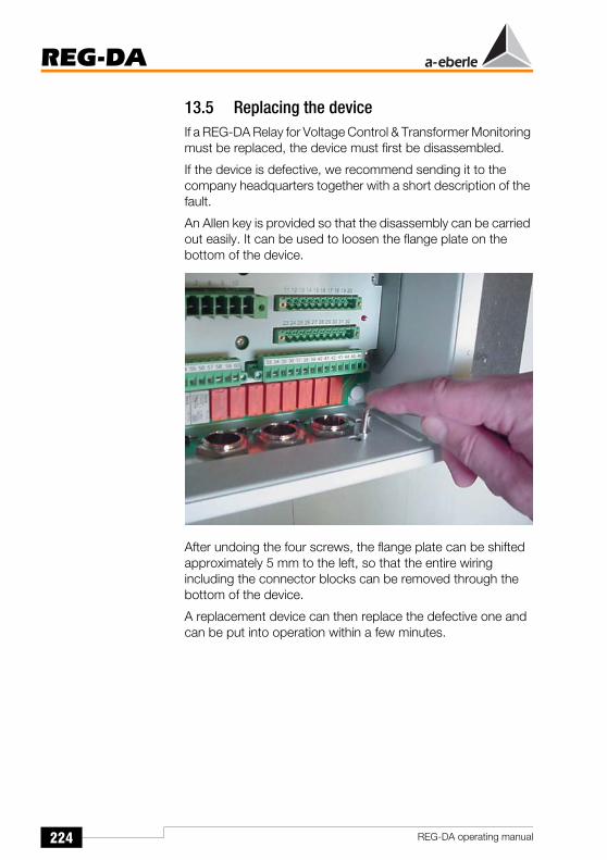
224
REG-DA
REG-DA operating manual
13.5 Replacing the deviceIf a REG-DA Relay for Voltage Control & Transformer Monitoring must be replaced, the device must first be disassembled.
If the device is defective, we recommend sending it to the company headquarters together with a short description of the fault.
An Allen key is provided so that the disassembly can be carried out easily. It can be used to loosen the flange plate on the bottom of the device.
After undoing the four screws, the flange plate can be shifted approximately 5 mm to the left, so that the entire wiring including the connector blocks can be removed through the bottom of the device.
A replacement device can then replace the defective one and can be put into operation within a few minutes.
225
REG-DA
REG-DA operating manual
14 Storage Information
The devices should be stored in clean, dry rooms. The devices and their respective replacement modules can be stored between -25 °C and +65 °C.
The relative humidity must not cause the formation of either condensation or ice.
We recommend that the storage temperature remains within the temperature range -10 °C to +55 °C to ensure that the built-in electrolytic capacitor does not age prematurely.
We also recommend that the device be connected to an auxiliary voltage every two years to reform the electrolytic capacitors. This procedure should also be carried out before the device is put into operation. Under extreme climatic conditions (tropics), this also simultaneously ensures “pre-heating” and helps to avoid the formation of condensation.
The device should be stored in the service room for at least two hours prior to being connected to the voltage for the first time so that it can become accustomed to the ambient temperature there and to avoid the formation of moisture and condensation.

226
REG-DA
REG-DA operating manual
15 Background Information
15.1 Regulator modeThe command variable W and the actual value X of the network voltage are continuously compared in the Relay for Voltage Control & Transformer Monitoring in order to maintain a constant network voltage. The command variable W is either a fixed value or a variable value which is the sum of fixed setpoint values and the changeable voltage drop on the lines to the consumers.
The difference between the actual value X and the control variable W (the regulative deviation Xw) is calculated according to a selected function in the Relay for Voltage Control & Transformer Monitoring and summed until a specified integral value is reached. As soon as this integral value is reached, the integrator is set to zero and a signal (correcting variable) is simultaneously output which triggers the tap-changer (actuator) of the transformer and thus changes its ratio. The integration begins anew after each tap-change procedure.
The REG-DA Relay for Voltage Control & Transformer Monitoring functions as a three-tap change regulator with a deadband. No control commands are output if the actual value lies within the deadband.
The parameters for the time behaviour of the Relay for Voltage Control & Transformer Monitoring can be optimally adapted to the time behaviour of the network voltage (controlled system) so that a high degree of control quality (high voltage constancy) can be achieved with a low number of switching operations. This results in a low load on the tap-changer.
All of the Relays can control several transformers operating in parallel on one busbar without requiring further devices. The transformers are regulated according to a specific algorithm, e.g. so that the reactive part of the circulating current is minimised. Thus transformers with different outputs and different tap-change voltages can also be operated in parallel.

227
REG-DA
REG-DA operating manual
15.2 Command variable WThe command variable W for the voltage of the tap-changing transformer may either be a fixed value (setpoint value) or a variable value (setpoint value + a variable). A variable command variable W can consist of, for example, the sum of a fixed setpoint value and the share of the voltage drop on a line up to a certain point in the circuit. This makes it possible to maintain the voltage at a constant level even if the load and the primary voltage are changing.
15.2.1 Fixed command variableThe command variable W is input into the Relay for Voltage Control & Transformer Monitoring as a voltage setpoint value and remains constant. The Relay for Voltage Control & Transformer Monitoring maintains the voltage at the transformer within the tolerance band, independent of the primary voltage and the corresponding load current (the voltage drop on the line).
Adjusting the setpoint / Switching to a different setpoint valueNormally up to 4 setpoint values can be pre-selected. If the present setpoint value is to be changed, this change can be carried out on the Relay for Voltage Control & Transformer Monitoring either manually or by switching to another setpoint value which has already been pre-selected. At the same time the previous setpoint value becomes ineffective.
Uset
Iactual
e.g. Ib
Voltageregulation
Currentinfluence
Xu=f (Uactual, Uset)
Xi = f (I)
Xp = f (...)
Uactual
Parallelprograms
Gradient
Perm. Icr
Limitation
Integrator
Raise
Lower
=
=
(W)
(X)
(XW)

228
REG-DA
REG-DA operating manual
The change to another setpoint value can be activated either via an external signal or by using a background program.
15.2.2 Variable command variableThe command variable W for regulating the voltage at a given position on a line is the sum of a fixed setpoint value XR and the variable value of a correction value XK.
W [V] = XR [V] + XK [V]
The correction value XK takes the data of the assigned line and load into consideration (voltage drop Uf), so that the voltage at the given position − the load point of the line − can be held approximately constant.
It is assumed that the network is generally loaded symmetrically, i.e. that the current in each line is approximately the same. The REG-DA Relay for Voltage Control & Transformer Monitoring can therefore be connected to the current transformer of any line (L1, L2, L3).
Measuring the voltage drop Uf on the lineThe voltage drop Uf on the line between the transformer and the consumer is the difference between the r.m.s. values of both voltages on the busbar and at the load point. The voltage drop depends on the impedance of the line, the current strength and the cos ϕ at the consumer.
The following formula defines the impedance of a line:
Z = RL + j ω LL + 1 / j ω CL
Measuring the voltage drop Uf as a function of the rated currentWhen the reactances of the line can be neglected and the cos ϕ at the consumer remains constant, the voltage drop Uf can be measured as a function of the nominal current.
Uf = f (I, R)
The gradient of the Uf/IL characteristic line required for the correct measurement of Uf must be determined according to

229
REG-DA
REG-DA operating manual
the operating conditions. see "Nominal value of the gradient" on page 232.
Control variables for UfIf the cos ϕ at the consumer varies, it is possible to select the active I cos ϕ or the reactive I sin ϕ component of the current as the control variable for Uf rather than current intensity I itself. The reactive component has either a positive or negative sign to differentiate between an inductive or a capacitive load respectively.
Measuring the voltage drop as a function of the current strength and cos ϕ(LDC = line drop compensation)
If the reactance of the line when measuring the voltage drop cannot be neglected and the cos ϕ at the consumer is not constant, the following formula applies to measuring Uf:
Uf = (R + j XL) ⋅ (I cos ϕ2 - j I sin ϕ2) = R I (cos ϕ2 - j sin ϕ2) + XL I (sin ϕ2 + j cos ϕ2)
By inputting the values for R and XL, a replica of the line can be created in the Relay for Voltage Control & Transformer Monitoring. This enables the voltage difference (of the r.m.s. values) between the beginning of the line (transformer) and the selected load point to be measured in relation to the current intensity and the cos ϕ2. The value can then be used as the correction value Xk. see "Variable command variable" on page 228.
Uf = U1 - U2
The angle at the load point is defined as ϕ2. However, in most cases the difference between ϕ at the transformer and ϕ at the load point may be neglected (see example).
The current and voltage paths (L1, L2, L3 as well as S1/k and S2/l) must be correctly connected in order to be able to measure the correct angle.

230
REG-DA
REG-DA operating manual
Example:Given: R = 30 Ω; XL = 82 Ω; I = 100 A; cos ϕ2 = 0.7; U2 = 110 kV at the end of the line.
When calculating using voltage pointers (for complex quantities use the E-2.5.2 EXCEL program which can be downloaded from our website, www.a-eberle.de), the result is the following exact value Uf = U1 - U2 = 7.96 kV. (The angle difference of the voltage pointer between the feeding point and the load point is approximately 2°).
The voltage at the transformer must thus be regulated to the r.m.s. value U1 = 110 kV + 7.96 kV = 117.96 kV (command variable W).
Setting R and XL The differences between the entered values and the actual values of R and XL as well as the difference between the cos ϕ at the transformer and at the consumer (the indicators of U1 and U2 have different angles) can also be eliminated by readjusting R and XL.
If values exist for the inductive and resistive voltage drop between the feeding point and the load point, they can be converted to resistances (R and X) using a simple mathematical equation.
Divide the voltages by 10 and enter the resulting values as the resistances R and X.
Example: Ux = 12 V
Ur = 25 V
Thus:
X = 1.2 Ohms
R = 2.5 Ohms

231
REG-DA
REG-DA operating manual
15.2.3 Current-dependent setpoint value increment
Determining the voltage levels XR and UfThe voltage level XR (setpoint value) should correspond to the required voltage at a minimum current.
The voltage level Uf is a function of the gradient of the linear Uf/IL-characteristic line. Adding this voltage to the entered setpoint value XR (increasing the setpoint value) cancels out the voltage drop on the line.
Various programs are available for incrementing the setpoint value:
setpoint value increment dependent on apparent current
setpoint value increment dependent on active current
setpoint value increment dependent on reactive current.
The line-drop compensation using the LDC process was described in the previous chapter.
Apart from the LDC process, the most commonly used method is compensation based on the apparent current and this is described in more detail below.
Please observe that the positive or negative sign of the active power is taken into consideration when the current-dependent setpoint value is increased.
The current-dependent setpoint value increment is active if power is being consumed and is inactive when power is being supplied.
This procedure - which works in the interest of network operation - can only be carried out properly and reliably when the direction of the active power is input correctly.
Uf [V]
0
0
IL
107.5 V 21.5 kV
100 V 20 kV100 A 700 A 800 A
5 A0.625 A 4.375 A
4.688 V
6.563 V
7.5 V

232
REG-DA
REG-DA operating manual
In this case a positive sign for active power indicates incoming power (setpoint value increment permissible), whereas a negative sign indicates power supply, and the setpoint increment function is disabled.
The connections for both the voltage and the current must be correctly assigned in order to detect the direction of the active power.
Therefore, please check the connections for current and voltage, as well as the assignments (SETUP 5, F2) and lastly check the sign for active power in the measurement transducer mode.
Nominal value of the gradientThe nominal value of the gradient Gnom indicates the % change in the nominal voltage when the current strength changes from 0 to 100% of the I1n nominal current of the current transformer that is mounted in the network.
GNom = 100 V
(∆U in relation to ∆IL [A])
Thus for the voltage Uf = f (I)
Limitation of the voltage level UfTo prevent the command variable from exceeding a certain limit value in the event of overcurrent, the gradient of the linear Uf/IL characteristic line must be set to zero from a specified value of the current onwards. The characteristic line is horizontal after this point.
GNom %[ ] ∆U V[ ]UNom V[ ]---------------------- 100%⋅=
Uf V[ ] ∆U V[ ]=GNom %[ ]
100%------------------------ UNom V[ ]
Ipresent A[ ]I1N A[ ]
---------------------------⎝ ⎠⎛ ⎞⋅ ⋅=

233
REG-DA
REG-DA operating manual
Measuring the required gradientThe two value pairs, voltage and current strength, must be known at a light load as well as at full load to measure the required nominal value Gnom [%].
Please note that the gradient and the setpoint value cannot be set independently from each other for this type of characteristic line, because when Gnom [%] > 0%, the command variable W, which is already at the minimum current value Imin > 0, would be unintentionally increased.
Example:The voltage at a particular point in the network is to be held constant at 20 kV under a variable load.
Nominal values of the voltage transformer:
U1n = 20 kV; U2n = 100 V; Knu = 200
Nominal values of the current transformer:
I1n = 800 A; I2n = 5 A; Kni = 160
Measured value pairs:
Primary side:
The difference between the currents∆I [A] = Imax - Imin = 700 A - 100 A = 600 A
Secondary side (primary values/Kni):
The difference between the currents∆I [A] = Imax - Imin = 4.375 A - 0.625 A = 3.750 A
Absolute voltage change∆U [V] = 21.5 kV - 20.5 kV = 1.0 kV
Voltage change in percent∆U [%] = (1.0 kV / 20.0 kV) 100 % = 5 %
Values atlight load Pmin
Values atfull load Pmax
Current intensity I Imin = 100 A Imax = 700 A
Control variable w wmin = 20.5 kV wmax = 21.5 kV

234
REG-DA
REG-DA operating manual
To raise the voltage of the transformer at full load (Imax) to 21.5 kV, the command variable must be ∆U = 1.0 kV, or 5% of the nominal voltage U1n higher than the set setpoint value XR.
Calculating the nominal value of the gradient Gnom [%]
Setpoint value reductionWith a light load and this gradient, the command variable W would be increased to
This corresponds to (100 A / 800 A) 6.67% = 0.83% of the nominal voltage.
Thus, the setpoint value XR would have to be set lower by 0.83% in order to maintain the voltage level at 20.5 kV during a light load.
Adjusting the setpoint valuesAt full load, the reduction of the setpoint value, however, causes the command variable W to be lowered so that a compromise must be found between the increase in Gnom [%] and the decrease in the reduction of the setpoint value.
GNom %[ ] ∆U V[ ]UNom V[ ]---------------------- 100 %
I1N∆I--------⋅⋅=
GNom %[ ] 1.0 kV20 kV---------------- 100 % 800 A
600 A--------------- 6.67 %=⋅⋅=
W 1IminI1n---------⎝⎛+
GNom100%--------------⎠
⎞ UNom⋅ ⋅=
W 1 100 A800 A---------------⎝⎛+
6.67%100%---------------⎠
⎞ 20.5 kV 20.67 kV =⋅ ⋅=
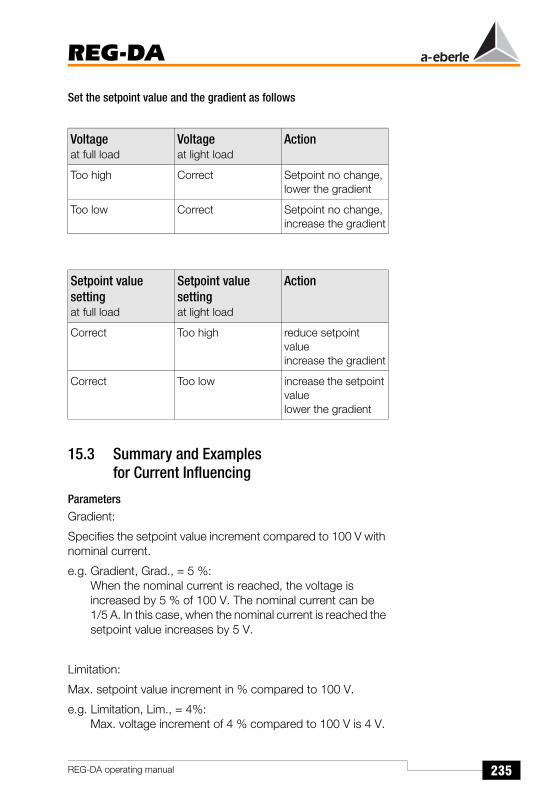
235
REG-DA
REG-DA operating manual
Set the setpoint value and the gradient as follows
15.3 Summary and Examplesfor Current Influencing
ParametersGradient:
Specifies the setpoint value increment compared to 100 V with nominal current.
e.g. Gradient, Grad., = 5 %:When the nominal current is reached, the voltage is increased by 5 % of 100 V. The nominal current can be 1/5 A. In this case, when the nominal current is reached the setpoint value increases by 5 V.
Limitation:
Max. setpoint value increment in % compared to 100 V.
e.g. Limitation, Lim., = 4%:Max. voltage increment of 4 % compared to 100 V is 4 V.
Voltageat full load
Voltageat light load
Action
Too high Correct Setpoint no change,lower the gradient
Too low Correct Setpoint no change,increase the gradient
Setpoint value settingat full load
Setpoint value settingat light load
Action
Correct Too high reduce setpoint valueincrease the gradient
Correct Too low increase the setpoint valuelower the gradient

236
REG-DA
REG-DA operating manual
No further increase takes place once the 4 V limit is reached.
The tolerance band remains unchanged. The permissible regulative deviation is not affect by the voltage increase.
The setpoint value, corrected to include the voltage increase, is not shown. However, it is indicated by the black colour of the arrow in the bar graph display.
Current-dependent voltage increase The currently-active setpoint value Uset,corr. is calculated as follows:
If ∆U > ∆B, then ∆U is limited to the size of ∆B.
Current-influencing programsApparent current: Ixd = I
The apparent current is used to determine the voltage increase. Increases only take place when the active power is positive.
Uset corr, Uset ∆U+= ∆U Grad100 %--------------- 100 V×
IxdIn------×=
Setpoint value [V]
Uppertolerance band
Setpoint
Lowertolerance band
106
107
105
104
103
102
101
100
99
980 0.2 0.4 0.6 0.8 1
Current normalised to 1/5 A.
Gradient = 5 %
Limitation = 4 %
Setpoint value = 100 V = 100 %
Permissible regulative deviation = 1 %

237
REG-DA
REG-DA operating manual
This method can be used to compensate the voltage drop if cosϕ is relatively constant.
Active current: Isd = Iw = I x cosϕ (with +/- sign)
The active current is used to determine the change in the setpoint value. If a negative active current flows (energy fed back), the setpoint value is decreased. The limitation is symmetrical and applies to both increases and decreases.
Reactive current: Ixd = Ib = I x sinϕ (with +/- sign)
The reactive current is used to determine the voltage increase. The increase/decrease is independent of the sign of the active power. It is increased if the reactive current is inductive, and decreased if it is capacitive.
This program is primarily used if the cosϕ of the network varies by a large amount.
LDC (Line Drop Compensation):
Used to compensate the voltage drop on a line when the active and reactive resistances are known. This process can also be used if the cosϕ of the consumer is not constant. The gradient is not required for this process. The limitation, however, continues to apply.
AbbreviationsIxd: Current used to determine the voltage increase [A]
I: Apparent current, measurement quantity [A]
Iw: Active current [A]
Ib: Reactive current [A]
In: Nominal current of the current transformer 1/5 A [A]
Grad.: Gradient [%]
Lim.: Limitation [L]
∆B: Limitation of the voltage increase [V]
∆U: Increase in setpoint value [V]
Uset: Specified setpoint value [V]
Uset,corr the setpoint value corrected to include the voltage increase [V]

238
REG-DA
REG-DA operating manual
15.4 Regulative deviations
15.4.1 Regulative deviation XwThe regulative deviation Xw is the difference between the actual value X of the regulating variable and the command variable W. The sign of the regulative deviation can be plus or minus.
NoteThe regulative deviation Xw corresponds to the negative regulation difference Xd.
15.4.2 Permissible regulative deviation XwzTo minimise the number of switches of the tap-changer, a deviation in the network voltage from the command variable W is tolerated within certain limits, i.e. a specific regulative deviation is permissible.
This permissible regulative deviation Xwz is entered as a ± n% of the control variable W (independent of all the other limit values expressed in %) and sets the limits for the maximum permissible relative fluctuation of the network voltage above and below the control value W. For this reason the absolute limit values of the tolerance band are dependent on the set command variable W.
When the network voltage dips into this tolerance band, the regulation procedure is interrupted and the integrator is set to zero so that the regulation/integration process only begins again when the network voltage overshoots or undershoots the limits of the tolerance band.
Fluctuations in the network voltage within the permissible regulative deviation have no effect on the regulation procedure.
Xw V[ ] X V[ ] W V[ ] Xw %[ ] W V[ ]⋅100 %
------------------------------------=–=
Xw %[ ] Xw V[ ]W V[ ]
---------------- 100 %⋅=
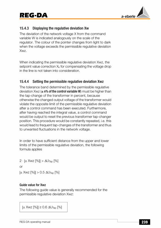
239
REG-DA
REG-DA operating manual
15.4.3 Displaying the regulative deviation XwThe deviation of the network voltage X from the command variable W is indicated analogously on the scale of the regulator. The colour of the pointer changes from light to dark when the voltage exceeds the permissible regulative deviation Xwz.
When indicating the permissible regulative deviation Xwz, the setpoint value correction Xk for compensating the voltage drop in the line is not taken into consideration.
15.4.4 Setting the permissible regulative deviation XwzThe tolerance band determined by the permissible regulative deviation Xwz (± n% of the control variable W) must be higher than the tap-change of the transformer in percent, because otherwise the changed output voltage of the transformer would violate the opposite limit of the permissible regulative deviation after a control command has been executed. Furthermore, after having reached the integral value, a control command would be output to reset the previous transformer tap-changer position. This procedure would be constantly repeated, i.e. this would lead to frequent tap-changes of the transformer and thus to unwanted fluctuations in the network voltage.
In order to have sufficient distance from the upper and lower limits of the permissible regulative deviation, the following formula applies
2 ⋅ |± Xwz [%]| > ∆UTap [%]
or
|± Xwz [%]| > 0.5 ∆UTap [%]
Guide value for XwzThe following guide value is generally recommended for the permissible regulative deviation Xwz:
|± Xwz [%]| ≥ 0.6 ∆UTap [%]
240
REG-DA
REG-DA operating manual
Example for determining the permissible regulative deviation
Nominal voltage UNom = 100 kV
Number of levels ± 15
Setting range 85 kV ... 115 kV
Tap-change increment: (115 kV - 85 kV): 30 levels =1 kV / tap-change
Thus 1 kV corresponds to the value of 1% of Unom
With this data, the permissible regulative deviation Xwz should not be less than the value Xwz = ± 0.6 ⋅ 1.0 kV = ± 0.6 kV (± 0.6%) The absolute limits are thus 100.6 kV and 99.4 kV.
If, for example, the upper limit is exceeded and the voltage is set back by one tap-change, the voltage is reduced to 100.6kV – 1.0 kV = 99.6 kV, i.e. the lower limit of 99.4 kV is not undershot. The voltage remains within the range of the permissible regulative deviation.

241
REG-DA
REG-DA operating manual
15.5 Monitoring extreme operating values(faults)
If a fault occurs in the network, e.g. inadmissibly or extremely high/low voltages or currents, the Relay for Voltage Control & Transformer Monitoring must not switch the transformer tap-changer to the highest or lowest tap-changer position. This occurs to prevent the network voltage having an impermissible value after the cause of the fault has been eliminated. These monitoring tasks are carried out by additional limit signals.
15.5.1 Limit signal
Switching time delayThe difference in time between when the limit value is reached and when the signal is transmitted is defined as the time delay. A specific time delay can be selected (parameterised) for each limit signal.
NotePlease note that the actual switching time delay can exceed the parameterised switching time delay by up to 2 seconds. This difference is due to the procedure selected for determining the measurement values.
Switching hysteresis, switching difference XsdThe difference in the input values between the switching on and off of the limit signal after the limit value violation has disappeared is defined as the switching difference. The hysteresis Xsd has a standard value of 1% of 100 V (corresponds to 1 V).
Assignment of the limit signalEach of the following limit values is monitored by one limit signal. A special additional function is activated for certain types of limit signals.
In the menu you have the option of selecting whether a binary output or LED should be activated if a limit value violation occurs.

242
REG-DA
REG-DA operating manual
NoteAny number of additional limit signals can be generated via the REG-L programming language (as a background program).
Setting the limit values/plausibility checkThe limit signal can be set freely for each limit signal within a given range. Therefore the user must check the logical relations of the values with each other.
Limit signal trigger (G1)When U > G1: Activation of the INHIBIT LOW regulator function (no control commands are output) in the event of undervoltage.
Setting range: 100 V ≤ G1 ≤ 150 V
NoteThe tripping can only be entered as an absolute value, because there is also only one voltage that may not be exceeded under any circumstances, regardless of the selected setpoint value.
The limit signal can be allocated to a binary output (R3 ... R11) if required. Furthermore, the limit value violation can be signalled by a freely programmable LED (LED1 ... LED12).
Backwards high-speed switching limit signal (G2)When U > G2: Activation of the BACKWARDS HIGH-SPEED SWITCHING function (for more information on the fastest series of control commands, see "High-speed switching add-on" on page 246).
Setting range: 1.00 X0 ≤ G2 ≤ 1.35 X0 (0% ... +35%)
The limit value is normally given as a %.
X0 represents the reference value (setpoint).
No more control commands will be output after the dip into the tolerance band ± Xwz.
The limit signal can be allocated to a binary output (R3 ... R11) if required. Furthermore, the limit value violation can be signalled by a freely programmable LED (LED1 ... LED12).

243
REG-DA
REG-DA operating manual
Forward high-speed switching limit signal (G3)When U < G3: Activation of the FORWARDS HIGH-SPEED SWITCHING function (for more information on the fastest series of control commands, see "High-speed switching add-on" on page 246).
This function is not available if the Relay for Voltage Control & Transformer Monitoring is operated in the “Creeping Net Breakdown” mode.
Reason: If the Relay for Voltage Control & Transformer Monitoring changes to high-speed switching when the “creeping net breakdown” function is switched on, the conditions may be fulfilled (depending on parameterisation) under which the Relay for Voltage Control & Transformer Monitoring detects a creeping net breakdown and changes to blocking without the voltage having reached the permissible tolerance band.
Setting range: 0.65 X0 ≤ G3 ≤ 1.00 X0 (-35% ... 0%)
The limit value is normally given as a %.
X0 represents the reference value (setpoint).
The limit signal can be allocated to a binary output (R3 ... R11) if required. Furthermore, the limit value violation can be signalled by a freely programmable LED (LED1 ... LED12).
Limit value transmitter > U (G4)The overvoltage >U is a limit value which only influences the regulation in special operating circumstances.
If the voltage exceeds the >U limit then all “raise” commands are surpressed.
The limit value particularly influences the regulation if operating with several setpoints and using an absolute value (100 V / 110 V) as the limit value for >U.
Setting range: 0 ... +25% *
Further information: see "> U Overvoltage" on page 118
The limit signal can be allocated to a binary output (R3 ... R11) if required. Furthermore, the limit value violation can be signalled by a freely programmable LED (LED1 ... LED12).

244
REG-DA
REG-DA operating manual
Limit-value transmitter >I (G5)I > G5: Activation of the STANDSTILL regulator function if undercurrent occurs (no issuing of control commands). However, the STANDSTILL function will only be activated if it has been previously activated in the menu “Add-On 5”.
The selected rated value (1 A or 5 A) always applies as the limit value reference X0.
Setting range: 1.00 X0 ≤ G5 ≤ 2.10 X0 (0% ... 210%)
The limit signal can be allocated to a binary output (R3 ... R11) if required. Furthermore, the limit value violation can be signalled by a freely programmable LED (LED1 ... LED12).
Limit value transmitter < U (G6)The undervoltage <U is a limit value which only influences the regulation in special operating circumstances.
If the voltage falls below the <U limit, all “lower” commands are surpressed.
The limit value particularly influences the regulation if operating with several setpoints and using an absolute value (100 V / 110 V) as the limit value for <U.
Setting range: -25% ... 0% *
Further information: see "< U Undervoltage" on page 117
The limit signal can be allocated to a binary output (R3 ... R11) if required. Furthermore, the limit value violation can be signalled by a freely programmable LED (LED1 ... LED12).
NoteThe <U message is suppressed for voltages < 20 V for firmware version 2.00 onwards.
Limit-value transmitter <I (G7)I < G7: Activation of the STANDSTILL regulator function in the event of undercurrent (no issuing of control commands). However, the STANDSTILL function will only be activated if it has been previously activated in the menu “Add-On 5”.
Setting range: 0.0 X0 ≤ G7 ≤ 1.00 X0
The selected rated value (1 A or 5 A) always applies as the limit value reference X0 (also refer to Add-On 5, F2).

245
REG-DA
REG-DA operating manual
The limit signal can be allocated to a binary output (R3 ... R11) if required. Furthermore, the limit value violation can be signalled by a freely programmable LED (LED1 ... LED12).
NoteThe <I message is suppressed for voltages < 20 V for firmware version 2.00 onwards.
Inhibit low limit value transmitter (G8)When U < G8: Activation of the limit signal and of the STANDSTILL regulator function (no issuing of control commands see "Relay for Voltage Control & Transformer Monitoring inhibit low function" on page 247).
Setting range: 0.25 X0 ≤ G8 ≤ 1.00 X0 (-75% ... +0%)
The limit value is normally given as a %.
X0 represents the reference value.
You can chose 100 V or 110 V as the reference value for the setpoint (also refer to Add-On 5, F2).
The limit signal can be allocated to a binary output (R3 ... R11) if required. Furthermore, the limit value violation can be signalled by a freely programmable LED (LED1 ... LED12).
Reference value X0 and reference value for the limit valuesThe upper and lower limit value may be set as a relative value in % of the current setpoint value or as an absolute value in relation to the nominal value of the voltage Unom see "Factory Settings of the Parameters" on page 303.
Example for relative limits:
If the “Setpoint value X” is selected as the reference value, all of the limit values change in relation to the respective entered setpoint value.
Setpoint value: X = 102.0 V; limit values: ± 10%;
thus the upper limit is 112.2 V and the lower limit is 91.8 V.
Example for absolute limits:
If “Unom= 100 V” is selected as the reference value, all of the limit values refer to the nominal voltage of 100 V and are independent of the current setpoint value.
246
REG-DA
REG-DA operating manual
Reference value: Unom = 100 V, Setpoint: 105 V, limit values: ± 10% of Unom; thus the lower limit is 90 V and the upper limit is 110 V.
15.6 Add-Ons
15.6.1 High-speed switching add-onUsing the high-speed switching add-on switches off the reaction delay (regulation behaviour, see Page 252), i.e. the control commands for the tap-changer are output in the shortest possible time sequence. The Relay for Voltage Control & Transformer Monitoring quickly regulates the tap-changer via successive control commands in the same direction (RAISE or LOWER) back to a tap-changer position with which the voltage of the transformer is within the permissible regulative deviation. The high-speed switching then becomes inactive again. This ensures that transformer output voltages that are too high or too low are quickly rectified.
The user can set the shortest time between control commands (the tap-changer in operation time) according to the time requirement of a tap-change operation(SETUP 5, F1, F2) so that only command change operations that can be carried out are given.
There are two different types of control to avoid the tap-changer drives being triggered by a sequence of control commands that is too fast.
If a Relay for Voltage Control & Transformer Monitoring input E1 ... E16 is configured as the tap-changer in operation input (with the exception of E5 and E6), the Relay for Voltage Control & Transformer Monitoring will not output the control commands until 2 s after the tap-changer in operation “drops”.
If the tap-changer in operation is not output to the Relay for Voltage Control & Transformer Monitoring, the relay will output the control commands with a time separation corresponding to the set “maximum time tap-changer in operation” (SETUP 5 - Add-On 1).

247
REG-DA
REG-DA operating manual
ActivationThe high-speed switching of the Relay for Voltage Control & Transformer Monitoring is activated either internally or externally via a binary signal. A binary input signal can also be used to activate the high-speed switching operation even if the actual voltage value is not sufficient to require it.
15.6.2 Relay for Voltage Control & Transformer Monitoring inhibit low function
The output of control commands to the tap-changer is blocked in inhibit low (standstill) mode (the output is “set to a standstill”). The standstill is active until the network voltage no longer violates the limit value for the standstill. The Relay for Voltage Control & Transformer Monitoring will continue to function again normally approximately 5 s after the network voltage violation has ended.
ActivationThe Relay for Voltage Control & Transformer Monitoring is switched to inhibit low either internally (standard program) or externally via a binary signal.
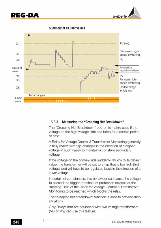
248
REG-DA
REG-DA operating manual
Summary of all limit values
15.6.3 Measuring the “Creeping Net Breakdown”The “Creeping Net Breakdown” add-on is mainly used if the voltage on the high voltage side has fallen for a certain period of time.
A Relay for Voltage Control & Transformer Monitoring generally initially reacts with tap-changes in the direction of a higher voltage in such cases to maintain a constant secondary voltage.
If the voltage on the primary side suddenly returns to its default value, the transformer will be set to a tap that is too high (high voltage) and will have to be regulated back in the direction of a lower voltage.
In certain circumstances, this behaviour can cause the voltage to exceed the trigger threshold of protection devices or the “tripping” limit of the Relay for Voltage Control & Transformer Monitoring to be reached which blocks the relay.
The “creeping net breakdown” function is used to prevent such situations.
Only Relays that are equipped with two voltage transformers (M3 or M9) can use this feature.
Tripping
Backward high-speed switching
>U
Permissible regulative deviation
<UForward high-speed switchingUndervoltage inhibit low
Tap-changes
G1
G2
G4
G3
G8
setpoint value
G6
RaiseLower

249
REG-DA
REG-DA operating manual
The “creeping net beakdown” function can only be derived from the overvoltage.
If only the control voltage (undervoltage) is available to the Relay for Voltage Control & Transformer Monitoring, it is not possible to ascertain whether the voltage dip is caused by a load or whether the reduction of the voltage is caused by a dangerous situation on the high voltage side.
If the regulative deviation is so large that - during a certain time period - more than a specified number of control commands in the RAISE direction is required to eliminate the regulative deviation, the REG-DA can react in two different ways:
The Relay for Voltage Control & Transformer Monitoring does not output any further control commands. It leaves the “AUTOMATIC” operating mode and remains in the “MANUAL” operating mode until it is switched back into “AUTOMATIC” mode, either via the manual key or via a remote control command.
The Relay for Voltage Control & Transformer Monitoring blocks all further control commands for a lock time (1 min ... 20 min). This lock is automatically removed if:a) the specified lock time has expiredorb) when the first LOWER control
command is output (i.e. when the upper limit of the regulative deviation is violated.
The “creeping net breakdown” function is canceled if the measurement quantity returns to being within the permissible range or if a lower command is issued.
The “Creeping Net Breakdown” function suppresses the “High-Speed Forward Switching” function.

250
REG-DA
REG-DA operating manual
15.6.4 “Maximum tap-change difference” monitoring Add-On
A tap-change difference can only occur when at least two transformers are considered.
If parallel programs that use the circulating reactive current process are used, then the transformers are always regulated to different tap-change positions if the transformers that are working in parallel are different (uk, number of tap-change positions, etc.).
The “maximum tap-change difference” parameter can be used to limit the difference.
If the specified tap-change difference is reached, the Relay for Voltage Control & Transformer Monitoring will no longer carry out tap-change operations if doing so would cause the circulating reactive current to reduce further.
The ParErr error flag is used for the monitoring.
ParrErr stands for a faulty parallel operation in general (parallel error) and automatically switches a group of transformers operating in parallel from the Automatic operating mode to the Manual operating mode.
ParrErr is triggered when a tap difference occurs between two transformers operating in parallel which is larger than the specified “maximum tap-change difference”.
An alternative procedure can be specified if this behaviour is not desired. Otherwise only the Relay for Voltage Control & Transformer Monitoring that carried out the tap-change that lead to the permissible maximum tap difference being exceed will be switched over to the manual operating mode.
NoteIf you prefer this behaviour, please contact our company headquarters.
15.6.5 Add-On: monitoring the tap-changerAfter the control command has been output, the Relay for Voltage Control & Transformer Monitoring controls the correct switching of the tap-changer so that the tap-change signal (tap-changer in operation) that is returned by the tap-changer is measured and compared with the value of the maximum tap-

251
REG-DA
REG-DA operating manual
change in operation time which was previously set via the menu (Setup 5, add-on 1).
If the tap-change signal continues to be output for a longer period of time, it is possible that the tap-changer has an error. The operation of the tap-changer can be interrupted using one of the freely programmable outputs R3 ... R11.
In this case the Laufl-F. or the Laufl-F+ function must be selected.
Laufl-F. causes a continuous signal at the selected output relay. Laufl-F+ only causes a wiping signal.
This output signal can be used to switch off the motor drive of the tap-changer (for example).

252
REG-DA
REG-DA operating manual
15.7 Time behaviour of the Relay for Voltage Control & Transformer Monitoring when a control command is output
RequirementsOptimal regulation behaviour is achieved when the operating requirements with regard to the voltage constancy need as few tap-changer operations as possible.
However, optimal regulation behaviour also requires that larger regulative deviations are regulated quicker than smaller regulative deviations.
NoteFor more information about understanding the regulation behaviour see "Integrated time program" on page 259!
Moreover, large regulative deviations should be rectified faster than small regulative deviations.
There are two measures for complying with the requirements specified above:
The regulative deviations are summed up to a specified integral value before the Relay for Voltage Control & Transformer Monitoring outputs a control command. If the network voltage dips into the tolerance band (± Xwz) before this integral value is reached, the integrator will be set to zero.
The regulative deviations are continuously evaluated before the integration according to the selected time relationship (∆U · t = const, REG-5A). Depending on the time interval, the evaluation factor increases either linearly or non-linearly with the value of the regulative deviation. Therefore, large regulative deviations (voltage deviations) are rectified faster than small ones. Large deviations in the voltage from the command variable trigger a control command after a short period of time (the integral value is reached quickly), whereas small voltage deviations take longer to trigger a control command.

253
REG-DA
REG-DA operating manual
Basic time and time factorThe evaluation factor variable of the regulative deviation Xw is not indicated directly, rather it is indicated as the time tg in seconds which passes from the beginning of the integration to the triggering of a control command provided that the regulative deviation is constant. Thus, the relationship between the regulative deviation and the reaction time can be recognised immediately.
If, for operational reasons, a slower reaction of the Relay for Voltage Control & Transformer Monitoring is desired, the time tg may be increased by multiplying it with the time factor FZ
(0,1 ... 30).
The time interval that elapses between the signalling of a control command and the actual triggering of a control command is in part determined by the switching time delay.
Time behaviour of the Relay for Voltage Control & Transformer MonitoringThe switching delay tv for a set permissible regulative deviation Xwz is thus dependent on the value of the present regulative deviation Xw, the selected characteristic line Xw/tg and the value of the set time factor Ft.
tv = tb · Ft

254
REG-DA
REG-DA operating manual
Since the permissible regulative deviation applies for both positive as well as for negative regulative deviations, only the positive side of the regulative deviation is usually depicted.
1%1%
Dead-
Reaction time tv
Per
mis
sibl
e re
gula
tive
devi
atio
n
setp
oint
val
ue
Per
mis
sibl
e re
gula
tive
devi
atio
n Present positiveregulative deviation
2%
3%
2%
3%
Present negativeregulative deviation
band

255
REG-DA
REG-DA operating manual
15.7.1 Determining the reaction delay tv
Hyperbolic characteristic curve Xw/tg (setting the time behaviour: ∆U*t=const)
Time factor = 1Set regulative deviation = 1%Constant present regulative deviation = 2%
Time until tap-change: 15 s
NotePlease note that the actual switching time delay can exceed the parameterised switching time delay by up to 2 seconds. This difference is due to the procedure selected for determining the measurement values.
Reaction time tg [sec]
30
25
20
15
10
5
00 1 2 3 4 5 6 7 8 9 10Present regulative deviation ∆UW [%]
Set permissible regulative deviation

256
REG-DA
REG-DA operating manual
A black bar increases from left to right at the bottom of the quasi-analogue display in regulator mode. This bar shows how long it will take until the next control command is issued.
The command is issued when the bar reaches the right hand edge of the display.
Exception: if the bar reaches the edge after 5 seconds whilst a tap-change is being carried out, the Relay for Voltage Control & Transformer Monitoring waits for this process to be completed before a new tap-change operation is started.
Hyperbolic characteristic curve Xw/tg (setting the time behaviour: REG-5A/E)
Time factor = 1Set regulative deviation = 1%Constant present regulative deviation = 2%
Time until tap-change: 10 s
NotePlease note that the actual switching time delay can exceed the parameterised switching time delay by up to 2 seconds. This difference is due to the procedure selected for determining the measurement values.
Progress bar
Reaction time tg [sec]
30
25
20
15
10
5
00 1 2 3 4 5 6 7 8 9 10Present regulative deviation ∆UW [%]
Set permissible regulative deviation

257
REG-DA
REG-DA operating manual
Further examples:
The permissible regulative deviation is set to Xwz = ± 2%, the time factor is set to 5. From the set of curves, the curve for Xwz = ± 2% has been selected. Using the curve, one obtains the following values:
How to proceed: Determine the point of intersection of the Y-coordinate at Xw with the curve of the permissible regulative deviation set on the Relay for Voltage Control & Transformer Monitoring. The value of the Y-coordinate corresponds to the basic time (see graphic).
A black bar increases from left to right at the bottom of the quasi-analogue display in regulator mode. This bar shows how long it will take until the next control command is issued..
The command is issued when the bar reaches the right hand edge of the display.
Exception: if the bar reaches the edge after 5 seconds whilst a tap-change is being carried out, the Relay for Voltage Control & Transformer Monitoring waits for this process to be completed before a new tap-change operation is started.
Xw [%] = [(X - W)/W] 100% 2% 3% 4% 5% 10%
Basic time tg (s) from the curve 30 s 16 s 10 s 7 s 2 s
Switching delay= basic time ⋅ time factor
5 ⋅ 30 s = 150 s
5 ⋅ 16 s = 80 s
5 ⋅ 10 s = 50 s
5 ⋅ 7 s = 35 s
5 ⋅ 2 s = 10 s
Progress bar

258
REG-DA
REG-DA operating manual
Linear characteristic line Xw/tg (setting the time behaviour: linear)
Set regulative deviation = 2%Constant present regulative deviation = 4%
Time until tap-change: 24 s
NotePlease note that the actual switching time delay can exceed the parameterised switching time delay by up to 2 seconds. This difference is due to the procedure selected for determining the measurement values.
A black bar increases from left to right at the bottom of the quasi-analogue display in regulator mode. This bar shows how long it will take until the next control command is issued..
The command is issued when the bar reaches the right hand edge of the display.
Exception: if the bar reaches the edge after 5 seconds whilst a tap-change is being carried out, the Relay for Voltage Control & Transformer Monitoring waits for this process to be completed before a new tap-change operation is started.
Reaction time tg [sec]
30
25
20
15
10
5
00 1 2 3 4 5 6 7 8 9 10Present regulative deviation ∆UW [%]
Set permissible regulative deviation
Progress bar

259
REG-DA
REG-DA operating manual
15.7.2 Integrated time programBoth the “∆U · t = const” and “REG- 5A/E” integrating time programs function in the following manner: after the integral of the voltage deviation ∆U and the time “t” has reached a specified value, the Relay for Voltage Control & Transformer Monitoring carries out a tap-change operation. The integrator is reset to zero after each tap-change operation.
If the voltage leaves the voltage band directly after a regulation procedure, the Relay for Voltage Control & Transformer Monitoring waits for the time specified in the algorithm (time from the characteristic curve multiplied with the time factor) before it initiates another control procedure.
Considering a bucket that is asymmetrically hung is helpful for understanding the two integrating procedures.
Picture 1 Picture 2Memory is filled with a Memory is filled with asmall regulative deviation large regulative deviation
The bucket tips when it is filled and this is analogous to a step-change operation carried out by the Relay for Voltage Control & Transformer Monitoring.
The analogy can be interpreted as follows:The greater the amount of water that flows into the bucket per unit time (the larger the voltage deviation), the quicker the bucket will fill up and tip over (the Relay for Voltage Control & Transformer Monitoring carries out a tap-change).
The smaller the amount of water that flows into the pail per unit of time (the smaller the voltage deviation), the longer it takes for the bucket to fill up and tip over (the Relay for Voltage Control & Transformer Monitoring carries out a tap-change).
260
REG-DA
REG-DA operating manual
The volume of water flowing (e.g. m3/unit time) corresponds to the voltage deviation.
This algorithm is based on the operating experience that small regulative deviations do not need to be rectified immediately, since in general they do not lead to a fault in the operation and also they can often “heal” themselves due to changes to the load (voltage returns to being within the bandwidth again).
The setpoint value and bandwidth boundaries are generally parameterised such that the voltage lies in the middle of the tolerance band.
In situations in which the voltage has changed such that it still lies within the band but close to the limit due to a particular load situation or a change to the primary voltage, small changes in the voltage or the load will always lead to a band violation.
However, since small regulative deviations are accompanied by a long integration or reaction time (it takes a long time for the bucket to fill), the voltage spends a large part of a particular amount of time outside the permissible band.
In such cases, specific intervention of the Relay for Voltage Control & Transformer Monitoring is desired.
15.7.3 Trend memoryThe “Trend memory” parameter can be used to accelerate all the algorithms.
It functions as follows:If the voltage leaves the tolerance band, the integration process is initiated − the bucket is filled. The Relay for Voltage Control & Transformer Monitoring performs a tap-change operation after a certain time has elapsed, which is determined by various parameters (the entered permissible regulative deviation, the actual regulative deviation, time factor).
If the voltage returns to the bandwidth without the Relay for Voltage Control & Transformer Monitoring having issued a tap-change command, the integrator is only reset to zero after the time that is parameterised for the trend memory has elapsed and not immediately.
However, if the voltage leaves the tolerance band again a short time later, the tap-change command will tend to be issued earlier because the integrator was not “emptied” and so will become full quicker.

261
REG-DA
REG-DA operating manual
However, once a tap-changing command is issued, the memory is set back to zero.
Therefore by using the “trend memory” parameter it can be achieved that the integrator is not immediately reset to zero if the voltage returns to being within the permissible tolerance band. If the voltage leaves the bandwidth at a point in time at which the memory has not been completely emptied, the Relay for Voltage Control & Transformer Monitoring can react earlier, since the integration procedure or “filling” procedure doesn’t start from zero, but rather at a higher level.
NoteThe function of the trend memory is explained using an example at the end of this section.
In general: The time, which is derived from the selected time program, is crucial to the memory loading process which triggers a tap-change operation when the memory is 100% full. However, the emptying of the memory is dependent on the time that is specified as the trend memory time.
NoteFor the delta U * t = const and REG 5A/E time programs, the time to be entered for loading of the memory can be derived from the appropriate curves. For the “Const” time program use time T1 (see Page 262).
A progress bar is incorporated in the regulator screen so that the present trend memory level can be judged by the user.
The progress bar is displayed as a black bar at the bottom of the screen. The bar is black when the memory is filling (i.e. the voltage lies outside of the tolerance band), and when it is emptying it changes colour and is light.
A tap-change operation is carried out when the bar reaches the right hand side of the screen. If the bar is invisible, this means that the trend memory has been completely emptied.
Rrogress bar

262
REG-DA
REG-DA operating manual
15.7.4 “Const” time program“Const” stands for constant reaction times, which cannot be adjusted in a sensitive manner to the respective regulative deviations, as is the case for the “∆U · t = const” or the “REG- 5A/E” procedures.
Two differing times are specified in the “Const” program, which cause the Relay for Voltage Control & Transformer Monitoring to perform a tap-change operation dependent on the extent of the regulative deviation.
Time T1 is effective if the voltage has a value that lies outside of the voltage band, but which can be brought back within the band with a single tap-change operation. T2 is valid when larger deviations have to be rectified.
The limit above which T2 is valid is therefore the same as the specified permissible regulative deviation.
Example:Permissible regulative deviation is 2%Actual regulative deviation is 3%
The Relay for Voltage Control & Transformer Monitoring uses the time T1
Permissible regulative deviation is 2%Actual regulative deviation is 5%
The Relay for Voltage Control & Transformer Monitoring uses the time T2
One advantage of this procedure is that in the case of regulative deviations which are larger than one tap-change, the operator
U
5%4%3%2%
setpoint value
T2T2
T1

263
REG-DA
REG-DA operating manual
can easily see when the next tap-change command will be issued.
A disadvantage compared to the other procedures is that over a long period of time the number of tap-changes will probably be larger than would be the case for the “∆U · t = const.” and “REG 5A/E” regulation algortihms.
As a general settings recommendation, the time T2 should be shorter than time T1 since large regulative deviations should be rectified more quickly than small ones.
Of course, the absolute values of the times in this case also depend on the specific conditions at the respective feeding point (load structure and behaviour etc.).
Sensible values for the trend memory can also only be derived from practical experience.

264
REG-DA
REG-DA operating manual
The “Const” time program and the way the trend memory operates should be explained using an example.
Parameters:
Time program: Const
T1: 40 seconds
Trend memory: 40 seconds
Permissible regulative deviation:± 1%
Diagrams 1 to 5
The entire situation is illustrated in five diagrams.Diagram 1 shows the progression of the voltage with time.
The voltage leaves the tolerance band at time T0 and returns again 20 seconds later.
5 * 4
/ 6
# & 7 2
1 6
4 3
4 3 *
4 3 ,
4 3
3 4
4 4 ) 4 * 4
4 4 ) 4 * 4
4 + 4 , 4
4 3
4 3 *
4 3 ,
4 3
3 4
4 4 ) 4 * 4
4+ 4 , 4 8 4
4 4 ) 4 * 4
4 + 4
, 4
8 4

265
REG-DA
REG-DA operating manual
After a further 10 seconds, the voltage leaves the permissible tolerance band again, and after 30 seconds a “lower” tap-change is issued by the Relay for Voltage Control & Transformer Monitoring which returns the value to within the band.
Diagram 2 shows how full the trend memory is (fill level). The Relay for Voltage Control & Transformer Monitoring performs a tap-change if the fill level reaches the normalised value “1”. If, on the other hand, the graph reaches the x-axis (0 value), the memory is completely emptied.
Diagram 3 shows when the Relay for Voltage Control & Transformer Monitoring issues a control command due to voltage deviations.
Diagrams 4 and 5 show the behaviour that occurs without the trend memory.
After 20 seconds the integrator for T1 is reset to zero, and after 30 seconds it begins to fill again − starting from zero.
A further 40 seconds (T1) are required to fill the memory to a level where a tap-change command is issued.
The way the trend memory operates can be best illustrated using diagram 2.
In order to explain the individual steps more clearly, the diagram has been divided into three sections, i, ii and iii.
Section i: The voltage is outside the voltage band, the integrator for time T1 is running.
If the voltage were to remain outside the tolerance band for 40 seconds, the Relay for Voltage Control & Transformer Monitoring would issue a control command. However, since the voltage returns to being within the tolerance band after 20 seconds, the regulation procedure is surpressed.
Section ii: The integrator for time T1 is half full (50% or 20 seconds in total). Emptying now begins according to the time that has been entered for the trend memory (100% = > 40 seconds).

266
REG-DA
REG-DA operating manual
Section iii: The voltage only remains inside the permissible tolerance band for 10 seconds and then exceeds the allowed voltage range again.
During this time the integrator could only be reduced from 50% to 25% full (20 seconds to 10 seconds). If the voltage now remains outside the band for a further 30 seconds the Relay for Voltage Control & Transformer Monitoring will issue a tap-change command.
For the voltage progression described in the example the time before the Relay for Voltage Control & Transformer Monitoring intervenes is reduced from 70 seconds to 60 seconds by employing the trend memory (refer also to diagrams 4 and 5).
15.7.5 Setting the time factor Ft
The time factor Ft can only be set by the ∆U · t = const, REG 5A/E and LINEAR time behaviours.
For a normal 24 hour load curve, an empirical value between 2 and 3 is suitable for the time factor. 3. If the 24-hour load curve is more constant, the rectification process can be accelerated by choosing a smaller time factor.

267
REG-DA
REG-DA operating manual
15.8 E-LAN (Energy Local Area Network)Each bus station (REG-DA) has two E-LAN interfaces. So-called line-to-line operation is enabled through these interfaces. In this operating mode, each Relay for Voltage Control & Transformer Monitoring works as a bus station and, at the same time, as a bus repeater which regenerates distorted rectangular forms and which increases the output level to the setpoint value. Up to 255 bus stations can be connected to the E-LAN.All bus stations can thus communicate with each other or be centrally controlled (see WinREG operating manual for selection and details).
Features 255 bus stations can be addressed
Multimaster structure
Integrated repeater function
Open ring, bus or combination of bus and ring
Record based on SDLC/HDLC frames
Transmission rate 15.6 ... 325 kbits/s
Telegram length 10 ... 30 Byte
Average throughput: approx. 100 telegrams / s
For technical data and the pin assignment, please refer to Page 41.
For information on the Configuration, see E-LAN (Energy Local Area Network) on page see "E-LAN (Energy-Local Area Network)" on page 101.
COM1AUTO MENUESC
F1
F2
F3
F4
F5
Status< U
> U> I
REG - D a. eberle gmbh
COM1
Status
a. eberle gmbhPAN - D
AUTO
< U1
> U2
> I
>> U3
>> U4
Auslösung
Störung
StörungRegler
Stufenschalter
Leitungsschalter
Rückführung
Lauflampe
läuft
Test
a. eberle gmbh
ANA-D
a. eberle gmbh
ANA-D
a. eberle gmbh
ANA-D
a. eberle gmbh
ANA-D
a. eberle gmbh
ANA-D
232SR
584SRLWL
IEC 61850IEC 60850-5-101/103/104MODBUS, SPABUS,LONMark, DNP 3.00
E-LAN
E-LAN
REG-BO
EOR-D
E-LAN
<mk5
REG-PCREG-BO
Fernwirkeinrichtung
BCD-CODE
REG-DPPAN-D REG-ST
REG-F(X)REG-S
BCD-CODE (Stufenstellung)
COM3RS485
BIN-D ANA-D
WinREG
Windows 95Windows 98Windows NTWindows 2000Windows XP
REGSys™ - Übersicht
MMU-D
E-LANRS485
COM1RS232
PQI-D
RS232
REG-D
REG-DAREG - DE
C OM1
a. eberle gm bh
AU TO MENUESC
F1
F2
F3
F4
F5
StatusM
A: REG-DE 12:34:00
Re gelnIpos = 98 .0 A +4.5 AV =
Uo = 0.85 % 2.0 Ad =
0.1
1
10
20A I m in I max 200A
U o
ABGE STIMMT
a. eberle gmbhPQI-D
COM1
Status
Reset
1
23
4
a. eber le gmbhEOR-D
C OM1
Status
Reset
1
23
4
a. ebe r le gmbhEOR-D
COM1
Status
Reset
1
23
4
a. ebe r le gmbhEOR-D
COM1
Status
Reset
12
34
a. ebe r le gmbhEOR-D
COM1
Status
Reset
12
34
a. eberle gmbhMMU-D
C OM1
Status
Reset
1
23
4
ehtE
tenr
AL-EN

268
REG-DA
REG-DA operating manual
E-LAN networking example
NoteAll of the devices of the REGSys™ family can be connected to the bus.REGSys™ components can be identified by the D after the hyphen.Example: REG-D, PQI-D, EOR-D, REG-DP, REG-DM, CPR-D, REG-DPA, ...
75 73EA+ EA- E+ E-
747671 69EA+ EA- E+ E-
7072
REG-DA
Bus left Bus right
2-wire bus
75 73EA+ EA- E+ E-
747671 69EA+ EA- E+ E-
7072
REG-DA
Bus left Bus right
75 73EA+ EA- E+ E-
747671 69EA+ EA- E+ E-
7072
REG-DA
Bus left Bus right
75 73EA+ EA- E+ E-
747671 69EA+ EA- E+ E-
7072
REG-DA
Bus left Bus right
75 73EA+ EA- E+ E-
747671 69EA+ EA- E+ E-
7072
REG-DA
Bus left Bus right
75 73EA+ EA- E+ E-
747671 69EA+ EA- E+ E-
7072
REG-DA
Bus left Bus right
2-wire bus
4-wire bus
Bus terminated
Bus terminated
Bus terminated
Bus terminated
Bus open

269
REG-DA
REG-DA operating manual
Types of linesEach of the E-LAN interfaces of a bus station can operate on a 2-wire line or on a 4-wire line. A 2-wire line is usually selected because this is the only option which permits a bus configuration with several bus stations on the same bus line.
The transmission line must be connected with a 100 Ω resistor at its beginning and end. Reflections can occur if the terminating resistance is not present. These distort the signal, increase the line damping, reduce the maximum transmission distance of the line and cause error functions.
The terminating resistances are already integrated into the REG-DA and can be switched on and off via the operating panel (termination).
TopologyThe topology of the network, i.e. the connection of each bus station to the bus, may be freely selected and combined.
The maximum permissible transfer rate depends on the selected operating mode (2-wire or 4-wire connection) and on the bus length.
The permissible separations are summarised in the table below:
Baud rate (KBaud)
4-wire 2-wire
15,6 1.2 km ≤ 0.1 km
31,2 1.2 km ≤ 0.1 km
62,5 1.2 km ≤ 0.1 km
125 1.0 km ≤ 0.1 km
375 0.8 km Not recommended

270
REG-DA
REG-DA operating manual
Bus segmentUp to 8 bus stations can be connected to one bus segment (line between two stations without boosters).
Up to 16 bus stations can be connected to one bus segment if all of the spur-line connections are as short as possible and the total loop resistance of the transmission line is < 100 Ohms.
Multimaster structureThe E-LAN has a multimaster structure, i.e. any bus station can operate as the bus master.
Each Relay for Voltage Control & Transformer Monitoring in the E-LAN can access all the data from all the other bus stations.
Unique addressingEach bus station on the E-LAN must be assigned a unique address. 255 freely selectable addresses are possible.
An address has the form: A, A1 ... A9, B, B1 ... B9, Z, Z1 ... Z4
Bus station indexEach bus station automatically generates an internal index of all bus stations with valid addresses in the E-LAN.
Every three seconds, each bus station in the E-LAN sends a so-called broadcast message to all of the other bus stations so that each bus station can adapt their internal index accordingly.
If the broadcast message of a bus station is interrupted for more than 20 seconds, the other bus stations will delete the corresponding bus station from their internal index. A list of all bus stations can be loaded via the operating panel.
The background program can be used to specify that the omission of a bus station is indicated via a signal (relay, LED) or a text message on the display.

271
REG-DA
REG-DA operating manual
15.9 Voltage regulation with transformers operating in parallel
If transformers operating in parallel do not have same data (EMK, uk, switching group, number of tap-change positions), an additional circulating reactive current will permanently flow within this parallel-switching circuit. This circulating reactive current generates losses and is independent of the load current and must therefore be avoided.
Regulation criteriaIn the case of parallel-switching on a busbar, the terminal voltage of all of the transformers - even with different tap-change positions - is compulsorily set to the same amount. Therefore the voltage alone cannot be a regulation criteria for transformers with different characteristic quantities. The voltage regulation must be supplemented by a circulating current regulation to be able to control transformers operating in parallel on a busbar to the appropriate voltage that is required and to the same tap-change position.
If all the transformers are the same, stable parallel-switching can be achieved using the voltage and tap-changes (master-slave, MSI).
Command variableThe REG-DA Relay for Voltage Control & Transformer Monitoring regulate the voltage on the undervoltage side (on the measurement transformer) of each transformer to a common command variable which depends on the sum current of the transformers operating in parallel.
Sum current (only relevant in the event of current influence)The currents of all of the transformers can be summed in one Relay for Voltage Control & Transformer Monitoring by networking the REG-DA Relay for Voltage Control & Transformer Monitoring of all of the transformers operating in parallel via one bus. This sum current and the selected gradient of the Uf/IL characteristic line is the uniform base for the current-dependent influence of the command variable W for all Relays.

272
REG-DA
REG-DA operating manual
Due to the use of a normalised sum current, the gradient of the Uf/IL characteristic can be set independently of the number and different types of characteristic data of the transformers operating in parallel (nominal power, short circuit voltage), so that changes in these parameters do not require resetting the gradient Gnom.
15.9.1 Regulation programsfor transformers operating in parallel
The following procedures are available:
∆I sin ϕ − procedure(minimisation of the circulating reactive current Icirc sin ϕ)
∆I sin ϕ (S) − procedure(minimisation of the circulating reactive current Icirc sin ϕ when operating transformers in parallel with various apparent powers)
Master-slave procedure (forced parallel operation, same tap-change position) for all the transformers in parallel.
∆cos ϕ − procedure(minimisation of the circulating reactive current Icirc sin ϕ for transformers that cannot communicate using E-LAN)
MSI - Master Slave Independent − procedure
ParametersParameters determine the extent to which the parallel regulation programs may affect regulation.
Different parameter menus are available depending on the type of regulation program selected for operating the transformers in parallel.
Influence of the circulating current regulation
Limitation of the influence of the circulating current regulation
Setpoint value of the cos ϕ of the network (cos ϕset)
Nominal power of the transformer
273
REG-DA
REG-DA operating manual
Transformer group list (addresses of relays activated by the menu or a binary signal (e.g. ParaGramer) that regulate transformers operating in parallel on a busbar)
15.9.2 Functional principle
Minimisation of the circulating reactive currentThe reactive component (Icirc sin ϕ) of the circulating current Icirc should ideally be zero or at least be minimised. Since the voltage cannot be changed continuously (tap-changes occur in increments), it is generally not possible to achieve the condition Icirc sin ϕ = 0.
To minimise the reactive component of the circulating current, each Relay for Voltage Control & Transformer Monitoring measures the reactive component I sin ϕ of the load currents for each transformer of the group list, calculates the circulating reactive current Icirc sin ϕ of the assigned transformer and sets the tap-changer position in such a way that this circulating reactive current is minimised.
15.9.3 Influence of the circulating current regulationThe size of the voltage change depends on the “influence of the circulating current regulation” parameters as well as on their degree of limitation. Larger permissible circulating currents (i.e. influence of circulating current regulation is lower) cause the precision of the circulating current regulation to be lowered which could result in tap-change differences of more than one tap-change.
Limitation of the influence of the circulating current regulationUnder normal operating conditions, the voltage regulation and the circulating current regulation are independent of each other (the limitation value of the influence of the circulating current regulation lies far above the normal operation value). Only under extreme conditions, including:
Operating transformers in parallel with previously different tap-change positions
Manual change of the tap-change position
∆cos ϕ-regulation for cos ϕnet ≠ cos ϕset

274
REG-DA
REG-DA operating manual
can the system be regulated to achieve either optimal voltage stability or optimal minimisation of the circulating reactive current. The user chooses his/her priority by setting the respective parameters.
This means that if voltage regulation is to be given priority over circulating current regulation, the influence of the circulating current regulation can be limited to a minimum value which must nevertheless be higher than zero.
15.9.4 Activation of the regulation programBoth the regulation program selected via the menu, and the addresses of the transformers/relays specified for operating in parallel are stored in a “group list” (SETUP 1, programs..., Par. parameters...). The operation in parallel and its reset are activated via a freely selectable binary input (SETUP 5, Add-On 6).
The corresponding activation may be carried out via a pulse or a high-level continuous signal.
A “self-learning” regulation program (ParaGramer) is also available through which the relays on the E-LAN permanently check which transformers are feeding on which busbar. The transformer group list is constantly updated in accordance with these results.
The ParProg parameter can be used to determine if a parallel program is active or not and can be assigned to a freely programmable LED or relay. An error function is indicated with (ParErr) or TapErr.
Further information can be found in chapter 9.

275
REG-DA
REG-DA operating manual
15.9.5 Description of the regulation programs
15.9.5.1 The ∆I sin ϕ procedureFunctional principle:
The value of the reactive current should be the same value, IbA = IbB = IbC = ... , for each of the transformers operating in parallel A, B, C,... .
If this condition is fulfilled, the circulating reactive current is zero.
Area of application:
Parallel operation on a busbar with a maximum of 10 transformers with nearly equal nominal power, nearly equal short circuit voltage and the same switching group. The tap-change increments may differ and the cos ϕ in the network can take any values requested.
Prerequisites:
The short circuit voltages, Uk of the transformers operating in parallel should only differ by a small amount: (0.90 ukn-1 < ukn < 1.10 ukn-1) and the nominal powers should be approximately the same.
The ∆I sin ϕ [S] program is available when transformers with different nominal powers are used.
Parameters to be entered:
Permissible circulating current (depends on the change in the circulating reactive current ∆Icirc sin ϕ = Ib** - Ib* per tap-change of the assigned transformer)
Group list of the relays/transformers (addresses of relays which can be activated via the menu, ParaGramer or a binary signal, that control transformers that are operating in parallel on a busbar)
Maximum tap difference between the transformers(SETUP 5, Add-On 6)

276
REG-DA
REG-DA operating manual
Permissible Icirc:
The correct value is derived as follows:
Operate all Relays in MANUAL mode and set all the transformers that are in the group list to the tap-change position that causes approximately the same terminal voltage. Note the value of the reactive current (Ib = Isin ϕ = reactive component of the load current)(measurement transducer mode). The value of the reactive current must be approximately the same in all of the other transformers.
Change each transformer successively by one tap-change position.
The reactive current changes. The difference between the new value (Ib** = 2nd measurement value) and the old value (Ib* = 1st measurement value) is considered to be the 1st approximation to the “perm. Icirc”.
Since the Relay for Voltage Control & Transformer Monitoring is supposed to reset the transformer that was changed by one level back to the previous tap-changer position, the permissible circulating current (perm. Icirc) can be set to a lower value than the value found in the 1st approximation. i.e.: permissible Icirc > 0.6 (Ib** - Ib*).
Low values can produce oscillations in the regulation, in particular when the transformers have different tap-changer increments or different short circuit voltages.
NotePlease note that the Relay for Voltage Control & Transformer Monitoring may under certain circumstances also issue a tap-change command when the permissible circulating reactive current is not exceeded.This is because a tap-change command is always issued if either the permissible voltage limit or the maximum permissible circulating reactive current is exceeded.

277
REG-DA
REG-DA operating manual
ParErrParrErr stands for a faulty parallel operation in general (parallel error) and automatically switches a group of transformers operating in parallel from the Automatic operating mode to the Manual operating mode.
To avoid having the transformers “diverge”, a max. tap difference (SETUP 5, Add-on 6) can be entered that is also monitored by the error flag “ParErr”.
If the set max. tap difference is exceeded, the ParErr error flag is set and the operation in parallel is switched to the manual operating mode − providing that Sysctrl Bit 6 has been set.
NoteBit 6 has been set on delivery!
Although the tap-change positions are not required for operation in parallel the ∆I sinϕ, ∆I sinϕ (S) and ∆cosϕ current-dependent procedures, the functioning of the tap-change can nevertheless be monitored if required.
Information on the tap-changer is not mandatory for operating in parallel (as mentioned above), because the regulation only derives the regulation commands from the current and the voltage (value and angle) and not from the tap-change position of the transformer.
TapErrThe TapErr error flag signals errors in the transmission of the tap-change position or errors in the coding/decoding of the tap-changer. In the∆sinϕ procedure, TapErr is only locally effective, i.e. it only affects the Relay for Voltage Control & Transformer Monitoring where the tap error has occurred.
We recommend assigning the error bit TapErr to a LED and/or a relay to inform the operating personnel about the status of the position return signal, making it easier to rectify the error.
If a transformer is operating in parallel, the TapErr error flag is set when - after a tap-change - the logically expected tap-change position is not established within 1.5 x running time of the tap-change.

278
REG-DA
REG-DA operating manual
In general, every Relay for Voltage Control & Transformer Monitoring expects the logically next step that follows a tap-change increment. If the reaction of the system is illogical, TapErr will be activated.
The following are considered to be tap errors:
1. Tap-changes in the wrong direction
Example: The Relay for Voltage Control & Transformer Monitoring outputs a “raise” command and the tap-changer reacts with a lower tap-change or the Relay for Voltage Control & Transformer Monitoring outputs a “lower” command and the tap-changer reacts with a higher tap-change.
Possible causes of the error: The raise and lower signals have been confused or the motor drive is behaving inversely.
Inverse behaviour implies that the Relay for Voltage Control & Transformer Monitoring increases the ratio in the event of a higher tap-change, thus lowering the voltage.
In most cases, it is to be expected that an increase in the tap-change position results in a higher voltage, whereas a decrease in the tap-change position results in a lower voltage.
Remedy: Exchange the raise and lower signals
2. No tap-change
Example:The Relay for Voltage Control & Transformer Monitoring outputs a command, but the tap-change position does not change.
In this case, it must be assumed that either the position confirmation signal or the motor drive is defective.
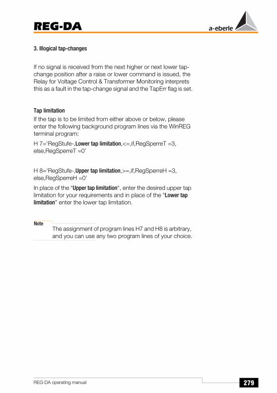
279
REG-DA
REG-DA operating manual
3. Illogical tap-changes
If no signal is received from the next higher or next lower tap-change position after a raise or lower command is issued, the Relay for Voltage Control & Transformer Monitoring interprets this as a fault in the tap-change signal and the TapErr flag is set.
Tap limitationIf the tap is to be limited from either above or below, please enter the following background program lines via the WinREG terminal program:
H 7=‘RegStufe-,Lower tap limitation,<=,if,RegSperreT =3,else,RegSperreT =0’
H 8=‘RegStufe-,Upper tap limitation,>=,if,RegSperreH =3,else,RegSperreH =0’
In place of the “Upper tap limitation“, enter the desired upper tap limitation for your requirements and in place of the “Lower tap limitation” enter the lower tap limitation.
NoteThe assignment of program lines H7 and H8 is arbitrary, and you can use any two program lines of your choice.
280
REG-DA
REG-DA operating manual
15.9.5.2 The ∆I sin ϕ (S) procedureFunctional principle:
The relationship between the value of the reactive current and the nominal power should be the same value IbA/SnA = IbB/SnB = IbC/SnC = ... for each of the transformers A, B, C,... operated in parallel!If this condition is fulfilled, the circulating reactive current is zero.
Area of application:
Transformers with different nominal powers which feed via one busbar in the network. Both the switching group as well as the short circuit voltages of the transformers should be as equal as possible because deviations may cause a different load utilisation of the transformers.
Prerequisites:
The permissible limits for different short circuit voltages are as follows: 0.90 ukn-1 < ukn < 1.10 ukn-1
Parameters to be entered:
Permissible circulating current (depends on the change in the circulating reactive current ∆Icirc sin ϕ = Ib** - Ib* per tap-change of the assigned transformer; lb* = 1st measurement value, lb** = 2nd measurement value). In the case of transformers switched in parallel that have different nominal powers, it is necessary to measure the permissible circulating current for each transformer separately and to enter it in the Relay for Voltage Control & Transformer Monitoring.
Nominal power of the connected transformer.
Group list of the relays/transformers (addresses of relays which can be activated via the menu, ParaGramer or a binary signal, that control transformers that are operating in parallel on a busbar)
Maximum tap difference between the transformers(SETUP 5, Add-On 6)

281
REG-DA
REG-DA operating manual
Permissible Icirc:
The correct value is derived as follows:
Operate all Relays in MANUAL mode and set all the address/transformers that are in the group list to the tap-change position, that causes approximately the same terminal voltage. Note the value of the reactive current Ib (to view in measurement transducer mode).
Change each transformer successively by one tap-change position.
The change to the reactive current ∆Ib, the difference between the new value (Ib** = 2nd measurement value) and the old value (Ib* = 1st measurement value), is considered to be the 1st approximation for the permissible “Icirc”.
Since the Relay for Voltage Control & Transformer Monitoring is supposed to then reset the transformer to the previous tap-change position, the permissible circulating current (permissible Icirc) must be set to the following value.
i.e.: permissible Icirc > 0.6 (lb** - lb*).
Oscillations in the regulation may occur for smaller values.
ParErrParrErr stands for a faulty parallel operation in general (parallel error) and automatically switches a group of transformers operating in parallel from the Automatic operating mode to the Manual operating mode.
To avoid having the transformers “diverge”, a max. tap difference (SETUP 5, Add-on 6) can be entered that is also monitored by the error flag “ParErr”.
If the set max. tap difference is exceeded, the ParErr error flag is set and the operation in parallel is switched to the manual operating mode − providing that Sysctrl Bit 6 has been set.
NoteBit 6 has been set on delivery!
Although the tap-change positions are not required for operation in parallel the ∆I sinϕ, ∆I sinϕ (S) and ∆cosϕ current-
282
REG-DA
REG-DA operating manual
dependent procedures, the functioning of the tap-change can nevertheless be monitored if required.
Information on the tap-changer is not mandatory for operating in parallel (as mentioned above), because the regulation only derives the regulation commands from the current and the voltage (value and angle) and not from the tap-change position of the transformer.
TapErrThe error flag TapErr signals errors in the transmission of the tap-change position or errors in the coding/decoding of the tap-changer. In the∆sinϕ procedure, TapErr is only locally effective, i.e. it only affects the Relay for Voltage Control & Transformer Monitoring where the tap error has occurred.
We recommend assigning the error bit TapErr to a LED and/or a relay to inform the operating personnel about the status of the position return signal, making it easier to rectify the error.
If a transformer is operating in parallel, the TapErr error flag is set when - after a tap-change - the logically expected tap-change position is not established within 1.5 x running time of the tap-change.
In general, every Relay for Voltage Control & Transformer Monitoring expects the logically next step that follows a tap-change increment. If the reaction of the system is illogical, TapErr will be activated.

283
REG-DA
REG-DA operating manual
The following are considered to be tap errors:
1. Tap-changes in the wrong direction
Example: The Relay for Voltage Control & Transformer Monitoring outputs a “raise” command and the tap-changer reacts with a lower tap-change or the Relay for Voltage Control & Transformer Monitoring outputs a “lower” command and the tap-changer reacts with a higher tap-change.
Possible causes of the error: The raise and lower signals have been confused or the motor drive is behaving inversely.
Inverse behaviour implies that the Relay for Voltage Control & Transformer Monitoring increases the ratio in the event of a higher tap-change, thus lowering the voltage.
In most cases, it is to be expected that an increase in the tap-change position results in a higher voltage, whereas a decrease in the tap-change position results in a lower voltage.
Remedy: Exchange the raise and lower signals
2. No tap-change
Example:The Relay for Voltage Control & Transformer Monitoring outputs a command, but the tap-change position does not change.
In this case, it must be assumed that either the position confirmation signal or the motor drive is defective.
3. Illogical tap-changes
If no signal is received from the next higher or next lower tap-change position after a raise or lower command is issued, the Relay for Voltage Control & Transformer Monitoring interprets this as a fault in the tap-change signal and the TapErr flag is set.

284
REG-DA
REG-DA operating manual
Tap limitationIf the tap is to be limited from either above or below, please enter the following background program lines via the WinREG terminal program:
H 7=‘RegStufe-,Lower tap limitation,<=,if,RegSperreT =3,else,RegSperreT =0’
H 8=‘RegStufe-,Upper tap limitation,>=,if,RegSperreH =3,else,RegSperreH =0’
In place of the “Upper tap limitation“, enter the desired upper tap limitation for your requirements and in place of the “Lower tap limitation” enter the lower tap limitation.
NoteThe assignment of program lines H7 and H8 is arbitrary, and you can use any two program lines of your choice.
15.9.5.3 Master-Slave procedure / MSI procedureOnly transformer types with identical electrical (output, short circuit voltage, voltage between the tap-changer positions, switching groups, etc.) and mechanical features (number of tap-change positions, position of the deadband) are suitable for MSI operation.
A different procedure should be used if one or more of the parameters differ.
In addition, it must be ensured that each Relay for Voltage Control & Transformer Monitoring receives the information regarding the tap-change position of “its” transformer.
The recording and transmission of the correct tap-change position is one of the mandatory prerequisites of the master-slave tap-change equalisation procedure.
Every potential “candidate” must be listed in the group list with its address in order to notify the system of the number of relays/transformers that should take part in parallel operation.
Moreover, the tap-change of each Relay for Voltage Control & Transformer Monitoring involved in the parallel-switching operation must be switched on (menu SETUP 5, Add-On 1, F4) before the parallel-switching operation is activated.

285
REG-DA
REG-DA operating manual
The MSI (master-slave-independent procedure) is a special version of the master-slave program (see "Parallel operation using the “Master-Slave-Independent (MSI)” procedure" on page 173).
After the parallel-switching operation has been activated, the master will regulate the slave, or - in the master-slave cycle - the slaves, to the tap-change position which it itself is in. It then switches to master-slave mode which causes all of the transformers involved in the parallel-switching operation to change taps simultaneously.
In the master-slave program, the slaves do not become slaves until they have reached the tap-change position that was specified by the master.As long as they are not in the same tap-change position, they remain in the slave mode.This differentiation and/or change can also be followed in the status line of the regulator.
The precondition for the master-slave operation is that each Relay for Voltage Control & Transformer Monitoring must be fed the present tap-change position of “its” transformer by means of a BCD, binary signal, mA signal or resistance value.
Parameters to be entered:
Transformer group list
Selection of activation, see chapter 9.
For operating the master-slave procedure it is mandatory that the tap-change position is signalled correctly. For this reason, error flags have been developed which immediately recognise errors and then set the regulation to the MANUAL operating mode if necessary.
TapErrIn the master-slave procedure, TapErr affects the entire group.
We recommend assigning the error bit TapErr to a LED and/or a relay to inform the operating personnel about the status of the position confirmation signal making it easier to rectify the error.
If a transformer is operating in parallel, the error flag TapErr is set when - after a tap-change - the logically expected tap-

286
REG-DA
REG-DA operating manual
changer position is not established within 1.5 x tap-changer runtime. In this case the entire group will be switched from AUTOMATIC to MANUAL.
In general, every Relay for Voltage Control & Transformer Monitoring expects the logically next step that follows a tap-change increment. If the reaction of the system is illogical, TapErr will be activated.
The following are considered to be tap errors:
1. Tap-changes in the wrong direction
Example: The Relay for Voltage Control & Transformer Monitoring outputs a “raise” command and the tap-changer reacts with a lower tap-change or the Relay for Voltage Control & Transformer Monitoring outputs a “lower” command and the tap-changer reacts with a higher tap-change.
Possible causes of the error: The raise and lower signals have been confused or the motor drive is behaving inversely.
Inverse behaviour implies that the Relay for Voltage Control & Transformer Monitoring increases the transformer ratio in the event of a higher tap-change, thus lowering the voltage.
In most cases, it is to be expected that an increase in the tap-change position results in a higher voltage, whereas a decrease in the tap-change position results in a lower voltage.
Remedy: Exchange the raise and lower signals
2. No tap-change
Example:The Relay for Voltage Control & Transformer Monitoring outputs a command, but the tap-change position does not change.
In this case, it must be assumed that either the position confirmation signal or the motor drive is defective.
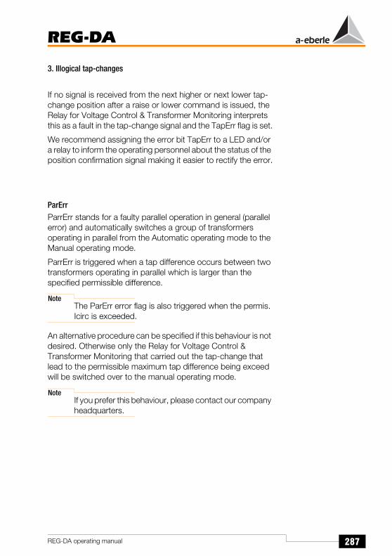
287
REG-DA
REG-DA operating manual
3. Illogical tap-changes
If no signal is received from the next higher or next lower tap-change position after a raise or lower command is issued, the Relay for Voltage Control & Transformer Monitoring interprets this as a fault in the tap-change signal and the TapErr flag is set.
We recommend assigning the error bit TapErr to a LED and/or a relay to inform the operating personnel about the status of the position confirmation signal making it easier to rectify the error.
ParErrParrErr stands for a faulty parallel operation in general (parallel error) and automatically switches a group of transformers operating in parallel from the Automatic operating mode to the Manual operating mode.
ParrErr is triggered when a tap difference occurs between two transformers operating in parallel which is larger than the specified permissible difference.
NoteThe ParErr error flag is also triggered when the permis. Icirc is exceeded.
An alternative procedure can be specified if this behaviour is not desired. Otherwise only the Relay for Voltage Control & Transformer Monitoring that carried out the tap-change that lead to the permissible maximum tap difference being exceed will be switched over to the manual operating mode.
NoteIf you prefer this behaviour, please contact our company headquarters.

288
REG-DA
REG-DA operating manual
15.9.5.4 The ∆cos ϕ procedureFunctional principle:
By means of the set cos ϕset, the ratio between the active current I cos ϕ and the reactive current I sin ϕ of the transformer (load currents) is set to the required value. Regulation is executed in such a way that the cos ϕ of the transformer is regulated to the set value cos ϕset.
The cos ϕ of the network is set on the Relay for Voltage Control & Transformer Monitoring. The Relay for Voltage Control & Transformer Monitoring should ideally keep this value constant. The constancy of the cos ϕnet value is the guage of quality of the regulation. Deviations from the set value negatively affect the regulation results because there is a small voltage change when cos ϕnet ≠ cos ϕset (inequality between the present value of the cos ϕ of the network and the set cos ϕset).
A self-adapting solution to the program can be implemented if the net cos ϕ changes by a large amount (depending on the time of day/year).
In this case the program continuously measures the cos ϕ at the connection point. The setpoint value of the net cos ϕ is adjusted after an integration over a selectable period of time. This means that a network with multiple feeding transformers that cannot communicate with each other can remain approximately free of circulating reactive currents.
Area of application:
Transformers which are feeding on one network independently of each other and where it is not possible to implement a bus link between the assigned relays.
Parameters to be entered:
Permissible reactive current difference > 0.6 x (lb** - lb*)
Limitation of the influence of the circulating current regulation
Setpoint value of the cos ϕ of the network (cos ϕset)

289
REG-DA
REG-DA operating manual
Although the tap-change positions are not required for operation in parallel the ∆I sinϕ, ∆I sinϕ (S) and ∆cosϕ current-dependent procedures, the functioning of the tap-change can nevertheless be monitored if required.
Information on the tap-changer is not mandatory for operating a parallel-switching operation (as mentioned above), because the regulation only derives the regulation commands from the current and the voltage (value and angle) and not from the tap-change position of the transformer.
TapErrTapErr is only effective locally, that is it only affects the Relay for Voltage Control & Transformer Monitoring where the tap error has occurred.
We recommend assigning the error bit TapErr to a LED and/or a relay to inform the operating personnel about the status of the position confirmation signal making it easier to rectify the error.
In general, every Relay for Voltage Control & Transformer Monitoring expects the logically next step that follows a tap-change increment. If the reaction of the system is illogical, TapErr will be activated.
The following are considered to be tap errors:
1. Tap-changes in the wrong direction
Example: The Relay for Voltage Control & Transformer Monitoring outputs a “raise” command and the tap-changer reacts with a lower tap-change or the Relay for Voltage Control & Transformer Monitoring outputs a “lower” command and the tap-changer reacts with a higher tap-change.
Possible causes of the error: The raise and lower signals have been confused or the motor drive is behaving inversely.
Inverse behaviour implies that the Relay for Voltage Control & Transformer Monitoring increases the transformer ratio in the event of a higher tap-change, thus lowering the voltage.

290
REG-DA
REG-DA operating manual
In most cases, it is to be expected that an increase in the tap-change position results in a higher voltage, whereas a decrease in the tap-change position results in a lower voltage.
Remedy: Exchange the raise and lower signals
2. No tap-change
Example:The Relay for Voltage Control & Transformer Monitoring outputs a command, but the tap-change position does not change.
In this case, it must be assumed that either the position confirmation signal or the motor drive is defective.
3. Illogical tap-changes
If the next higher or lower tap-change position is not signalled back after the tap-change position has been raised or lowered, the Relay for Voltage Control & Transformer Monitoring interprets the position check-back signal as being defective and sets the error flag TapErr.
We recommend assigning the error bit TapErr to a LED and/or a relay to inform the operating personnel about the status of the position confirmation signal making it easier to rectify the error.

291
REG-DA
REG-DA operating manual
15.9.5.5 The ∆cos ϕ emergency programFunctional principle:
In order to keep the circulating current regulation stable, even during bus faults (E-LAN), an emergency program is incorporated in the ∆I sin ϕ and ∆I sin ϕ (S) programs. This program is activated as soon as the Relay for Voltage Control & Transformer Monitoring recognises a bus error(E-LAN - Error). All relays connected to the E-LAN will return to their previous program 10 seconds after the bus error has been eliminated.
The ∆cos ϕ program is used as an emergency program, whereby the regulation is not carried out to the entered cos ϕset but to the last present cos ϕSum of the network that was measured by the Relay for Voltage Control & Transformer Monitoring (ϕSum = angle between the sum current and the network voltage). Thus the voltage regulation is not affected and the parallel operation of the transformers also remains stable.
If the cos ϕSum of the network changes (an event that usually occurs only slowly, not suddenly), the network voltage changes only slightly, because the Relay for Voltage Control & Transformer Monitoring tries to find a compromise between the minimum difference of the measured cos ϕSum of the network and the present cosϕSum of the network as well as the minimum difference between the command variable W and the actual value X of the voltage.
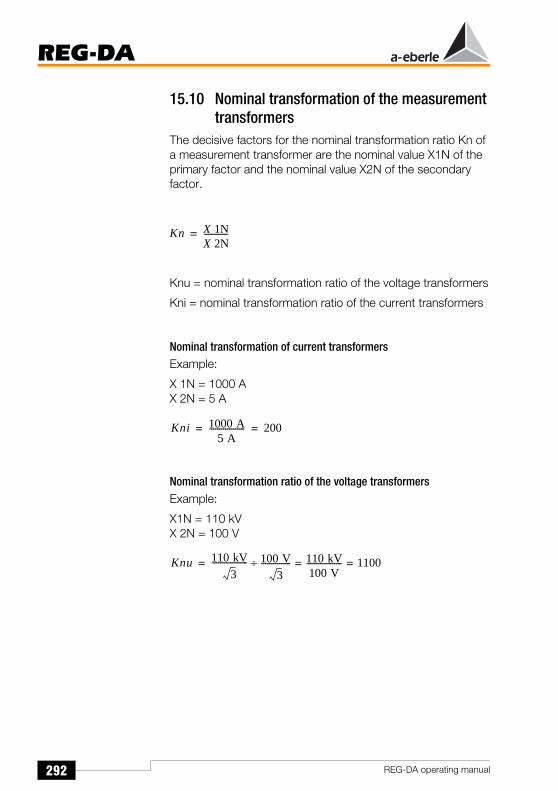
292
REG-DA
REG-DA operating manual
15.10 Nominal transformation of the measurement transformers
The decisive factors for the nominal transformation ratio Kn of a measurement transformer are the nominal value X1N of the primary factor and the nominal value X2N of the secondary factor.
Knu = nominal transformation ratio of the voltage transformers
Kni = nominal transformation ratio of the current transformers
Nominal transformation of current transformersExample:
X 1N = 1000 AX 2N = 5 A
Nominal transformation ratio of the voltage transformersExample:
X1N = 110 kVX 2N = 100 V
Kn X 1NX 2N------------=
Kni 1000 A5 A
------------------ 200= =
Knu 110 kV3
------------------ 100 V3
--------------- 110 kV100 V------------------ 1100= =÷=

293
REG-DA
REG-DA operating manual
15.11 Self-ConductEach active control level of the Relay for Voltage Control & Transformer Monitoring (MANUAL/ AUTOMATIC) maintains its status even after a failure of the auxiliary voltage.
If the auxiliary voltage is interrupted, the “WITH” self-conduct setting causes the Relay for Voltage Control & Transformer Monitoring to continue running in the AUTOMATIC operating mode after the event; this is only possible if the Relay for Voltage Control & Transformer Monitoring was operating in the AUTOMATIC operating mode before the malfunction occurred. In the situation mentioned above, the “WITHOUT” self-conduct setting would cause the Relay for Voltage Control & Transformer Monitoring to change to the MANUAL operating mode after the event.
15.12 LCD display
15.12.1 LCD contrastThe contrast can be changed (see "LCD contrast (display)" on page 94).
15.12.2 LCD SaverThe LCD display switches off after 1 hour.
15.12.3 Background illuminationThe background illumination switches off 15 minutes after the keypad was last used.
Pressing any key switches the background illumination on again.

294
REG-DA
REG-DA operating manual
16 Definition of the Abbreviations
Abbreviation Definition
OFF OFF
Trigger TriggerThe Relay for Voltage Control & Transformer Monitoring stops further regulation procedures until the limit value violation has been rectified.
AUTO Automatic operation
Triple-wound Triple-wound application
ELAN Err E-LAN error (error on bus)
ELAN-L E-LAN left
ELAN-R E-LAN right
up/down LED indicates raise or lower, when control command is given.
InputErr Input-ErrorIf the setpoint value change (SW1 to SW2) is carried out at the binary input, InputErr will become active if both signals are there at the same time. The Relay for Voltage Control & Transformer Monitoring retains the old value and displays InputErr.
TC-Err+ Exceeding the running time of the tap-changer indicated as a wiping signal
TC-Err. Exceeding the running time of the tap-changer indicated as a continuous signal
TC. i. Op Maximum time TC in operation lampThe time the motor drive requires to change from one tap to the next
LDC Line drop compensation
Par-Prog Parallel program activated or not activated

295
REG-DA
REG-DA operating manual
ParErr ParrErr stands for a faulty parallel operation in general (parallel error) and automatically switches a group of transformers operating in parallel from the Automatic operating mode to the Manual operating mode.If this behaviour is not desired, a different type of behaviour can be selected via the SysCtrl feature. In this case please contact our headquarters.
Please also refer to “Description of the regulation programs” on Page 275.
PhaseFail Function only available in PAN-D or relays with Feature M2. PhaseFail is active if one of the three phases fails.
TapErr TapErr is a signal that indicates a problem with the tap-change position. The name is derived from the term “tap error”.Unlike ParErr, Tap Err is only effective locally, i.e. it is only indicated on the Relay for Voltage Control & Transformer Monitoring on which the tap-changer position error has occurred. It can also switch the group working in parallel to MANUAL when operating in the master-slave or MSI procedure.
LEVEL Level-controlled function
PROG Function triggered by background program
creepNBD Creeping net breakdown
Quick High-speed switchingThe Relay for Voltage Control & Transformer Monitoring switches in the quickest possible time within the tolerance band
Inh. Low Setting to a standstillThe Relay for Voltage Control & Transformer Monitoring stops all further regulation until the limit value violation has been rectified
SP-1 Setpoint value 1
Abbreviation Definition

296
REG-DA
REG-DA operating manual
SP-2 Setpoint value 2
SP-3 Setpoint value 3
SP-4 Setpoint value 4
SP-decr. Decrease setpoint value via the binary input (lower)
SP-incr. Increase setpoint value via the binary input (raise)
SP2Level Level-controlled switching to setpoint value 2
Trans1/Trans1
Transit channel 1Binary input signal can be “given” to a freely-programmable relay.
Examples:BI 1 on Trans 1Rel 3 on Trans 1ã BI 1 = 1 ã REL 3 = 1
BI 1 = 0 ã REL 3 = 0
BI 1 on Trans 1Rel 3 on /Trans 1ã BI 1 = 1 ã REL 3 = 0
BI 1 = 0 ã REL 3 = 1
Trans2/Trans2
See Trans1
PG_CB ParaGramer, low-voltage side, Circuit breaker
PG_IS1 ParaGramer, low-voltage side, Isolator 1
PG_IS2 ParaGramer, low-voltage side, Isolator 2
PG_CP ParaGramer, low-voltage side, Bar coupler
PG_SC1 ParaGramer, low-voltage side, Line coupler 1
Abbreviation Definition

297
REG-DA
REG-DA operating manual
PG_SC2 ParaGramer, low-voltage side, Line coupler 2
PG_H_CB ParaGramer, High-voltage side, Circuit breaker
PG_H_IS1 ParaGramer, High-voltage side, Isolator 1
PG_H_IS2 ParaGramer, High-voltage side, Isolator 2
PG_H_CP ParaGramer, High-voltage side, Bar coupler
PG_H_SC1 ParaGramer, High-voltage side, Line coupler1
PG_H_SC2 ParaGramer, High-voltage side, Line coupler2
BCD1 BCD/BIN code, value 1
BCD2 BCD/BIN code, value 2
BCD4 BCD/BIN code, value 4
BCD8 BCD/BIN code, value 8
BCD10 BCD/BIN code, value 10
BCD20 BCD/BIN code, value 20
BCDminus BCD/BIN code, “-” sign
BIN16 BIN code, value 16
BIN32 BIN code, value 32
PANmiss Set if associated PAN - D is not available
Abbreviation Definition

298
REG-DA
REG-DA operating manual
LR_AH Local/remote operation together with the REG_LR device will be activated as soon as the input functions LR_AH and LR_STAT are used. These inputs are connected with the corresponding outputs of the REG_LR device. As long as the REG_LR device holds the status line LR_STAT active (1), the AUTO/MANUAL status of the Relay for Voltage Control & Transformer Monitoring will be determined by the input LR_AH (1:AUTO, 0:MANUAL). Raise/lower commands may only come from the Relay for Voltage Control & Transformer Monitoring drive (in the case of AUTO). As soon as the status of the REG_LR device falls (0), the Relay for Voltage Control & Transformer Monitoring will revert to the AUTO/MANUAL operating mode which applied 1s before the drop in the LR_STAT signal. The Relay for Voltage Control & Transformer Monitoring will then continue to work as usual.Special case: LR_STAT is not used, i.e. only the input function LR_AH is activated. In this case, it is always assumed that LR_STAT is active.
LR_STAT If only the LR_STATUS input function is used, the following applies:LR_STAT active (1): Remote operation, i.e. MANUAL/AUTO and raise/lower only via inputs or REG-L.
LR_STAT inactive (0):Local operation, i.e. MANUAL/AUTO and raise/lower only via the keypad.
T60s/1s Outputs a 1 s signal as a pulse (relay) or lights the LED every 60 s
COM2ACT Gives information about the status of the COM 2 (1: busy, 0: not busy)
Abbreviation Definition

299
REG-DA
REG-DA operating manual
NoteFurther parameters and hence abbreviations are required in certain circumstances depending on the additionally selected features (e.g. TMM).The descriptions of the statuses will be delivered with the appropriate operating manual update.

300
REG-DA
REG-DA operating manual
17 Symbols and their Definition
Symbol Definition
> I [%] Upper limit value of the current(of the transformer)
< I [%] Lower limit value of the current(of the transformer)
> U [%] Upper limit value of the voltage(of the transformer)
< U [%] Lower limit value of the voltage(of the transformer)
∆I [A] Difference between 2 current values
∆U [V] Difference between 2 voltage levels
AA1 ... AAn Analogue output (mA)
AI1 ... AIn Analogue input (mA)
BO1 ... BO Binary output(USt. : 10 V ... 50 V)
E1 ... En Binary input(USt. : 48 V ... 230 V)
Ft [1] Time factor for time behaviourof the Relay for Voltage Control & Transformer Monitoring
I1n [A] Nominal value of the primary current transformer(of the transformer)
I2n [A] Nominal value of the secondary current transformer(of the transformer)
Icirc [A] Circulating current in parallel-switched transformers
Icirc sin ϕ [A] Reactive component of the circulating current Icirc
I [A] Delivered load current of the transformer
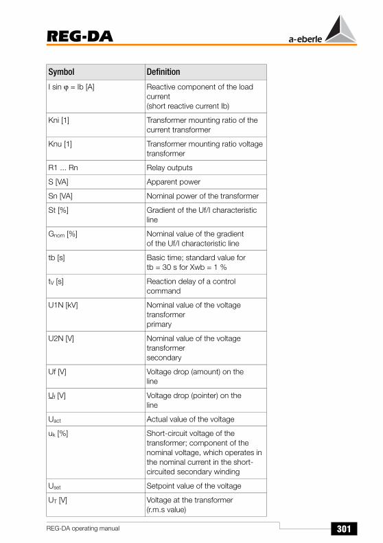
301
REG-DA
REG-DA operating manual
I sin ϕ = Ib [A] Reactive component of the load current(short reactive current Ib)
Kni [1] Transformer mounting ratio of the current transformer
Knu [1] Transformer mounting ratio voltage transformer
R1 ... Rn Relay outputs
S [VA] Apparent power
Sn [VA] Nominal power of the transformer
St [%] Gradient of the Uf/I characteristic line
Gnom [%] Nominal value of the gradientof the Uf/I characteristic line
tb [s] Basic time; standard value for tb = 30 s for Xwb = 1 %
tV [s] Reaction delay of a control command
U1N [kV] Nominal value of the voltage transformerprimary
U2N [V] Nominal value of the voltage transformersecondary
Uf [V] Voltage drop (amount) on the line
Uf [V] Voltage drop (pointer) on the line
Uact Actual value of the voltage
uk [%] Short-circuit voltage of the transformer; component of the nominal voltage, which operates in the nominal current in the short-circuited secondary winding
Uset Setpoint value of the voltage
UT [V] Voltage at the transformer(r.m.s value)
Symbol Definition
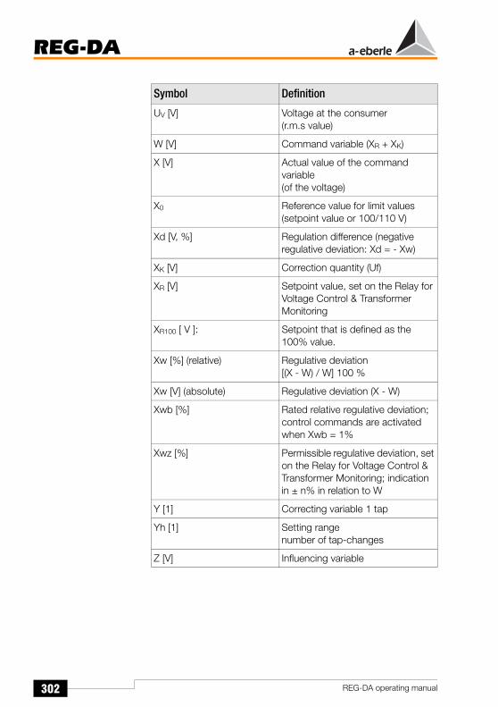
302
REG-DA
REG-DA operating manual
UV [V] Voltage at the consumer(r.m.s value)
W [V] Command variable (XR + XK)
X [V] Actual value of the command variable(of the voltage)
X0 Reference value for limit values(setpoint value or 100/110 V)
Xd [V, %] Regulation difference (negative regulative deviation: Xd = - Xw)
XK [V] Correction quantity (Uf)
XR [V] Setpoint value, set on the Relay for Voltage Control & Transformer Monitoring
XR100 [ V ]: Setpoint that is defined as the 100% value.
Xw [%] (relative) Regulative deviation[(X - W) / W] 100 %
Xw [V] (absolute) Regulative deviation (X - W)
Xwb [%] Rated relative regulative deviation; control commands are activated when Xwb = 1%
Xwz [%] Permissible regulative deviation, set on the Relay for Voltage Control & Transformer Monitoring; indication in ± n% in relation to W
Y [1] Correcting variable 1 tap
Yh [1] Setting range number of tap-changes
Z [V] Influencing variable
Symbol Definition

303
REG-DA
REG-DA operating manual
18 Factory Settings of the Parameters
Parameters Factory setting
SettingRange
Reference
Trigger 125.0 V 6.0 V ... 160.0 V −
Limitation(I) 0.0% ... 40.0% −
Actual value correction voltage
0.0 -20% ... +20% Unom
Actual value correction current
0.0 -20% ... +20% Inom
Kni 1.00 0.01 ... 10000 −
Knu 1.00 0.01 ... 4000 −
LDC(Line drop compensation)
R: 0.0 ... 30.0 ΩX: 0.0 ... 30.0 Ω
−
Regulative deviation, permissible
2% ±0.1% ... 10% setpoint value
Backward high-speed switching
10.0% 0.0% ... +35.0% setpoint value
Forward high-speed switching
-10.0% -35.0% ... 0.0% setpoint value
Setpoint value 1 ... 4 100 V 60.0 V ... 140.0 V −
Gradient (I) 0.0% 0.0% ... 40.0% −
Inhibit Low -25% -75.0% ... 0.0% Setpoint value or100/110 V
Undervoltage < U -10.0% -25% ... +10% Setpoint value or100/110 V
Overvoltage > U 10% 0.0% ... + 25.0% Setpoint value or100/110 V
> I 100.0% 0% ... 210% Inom
1 A / 5 A
< I 0.0% 0% ... 100% Inom
1 A / 5 A

304
REG-DA
REG-DA operating manual
Time factor 1.0 0.1 ... 30 −
Trigger time 0 s 0 ... 999 s −
Backward high-speed switching time
0 s 0 ... 999 s −
Forward high-speed switching time
2 s 2 ... 999 s −
Inhibit low time 0 s 0 ... 999 s −
Undervoltage time 0 s 0 ... 999 s −
Overvoltage time 0 s 0 ... 999 s −
Time > I, < I 0 s 0 ... 999 s −
Parameters Factory setting
SettingRange
Reference

305
REG-DA
REG-DA operating manual
19 Notes on the Interpreter Language
Notes on the Interpreter Language REG-L (REG-Language) can be ordered separately or can be downloaded from our website www.a-eberle.de orwww.regsys.de
Furthermore, all help texts may be displayed directly on the Relay for Voltage Control & Transformer Monitoring using a terminal program (? ).

REG-DA
306 REG-DA Operating Manual
20 Index
Symbols“++” symbols 149
Numbers1. setpoint value 111100% value 1112. setpoint value 11224 hour load curve 2662-wire line 101, 2693 conductor circuit 1873-phase current systems 244-wire line 2694-wire transmission technology (RS485) 101
AAbbreviations 294Absolute limits 245Active component 229Active current 288Activity lamp 294Actual value 52Actual value correction current 303Actual value correction voltage 303Actual value X 226Actuator 226Add-Ons 124Addresses (A ... Z4) 91Addressing 270Adjusting the setpoint 227Allen key 224Analogue channels 203Analogue input 300Analogue output 300Angle 229Angle difference 230Angular relationship 138Apparent power 301Application menu 187ARON circuit 53Aron circuit 29, 138
AUTO 294AUTO lock when E-LAN error occurs 133Automatic 294Auxiliary voltage 9, 29Auxiliary voltage failure 129, 293
BBackground illumination 293Background information 226Background program 100, 142, 144, 228, 242, 270, 295Backward high-speed switching time 304Band boundaries 260Band violation 260Basic settings 91Basic time 253, 301Battery 221Battery status 104Baud rate 214, 215BCD-coded signals 128Binary inputs 34Binary output 241Block diagram 21Booster 102Bridge 32Broadcast Message 270Bus 267Bus configuration 101Bus device index 270Bus error 151Bus errors 291Bus left 101Bus line 101Bus link 288Bus repeater 267Bus right 101Bus segment 270Bus station 267, 270Busbar 154, 226, 271, 273, 274, 275, 280Busbar replica 57, 163
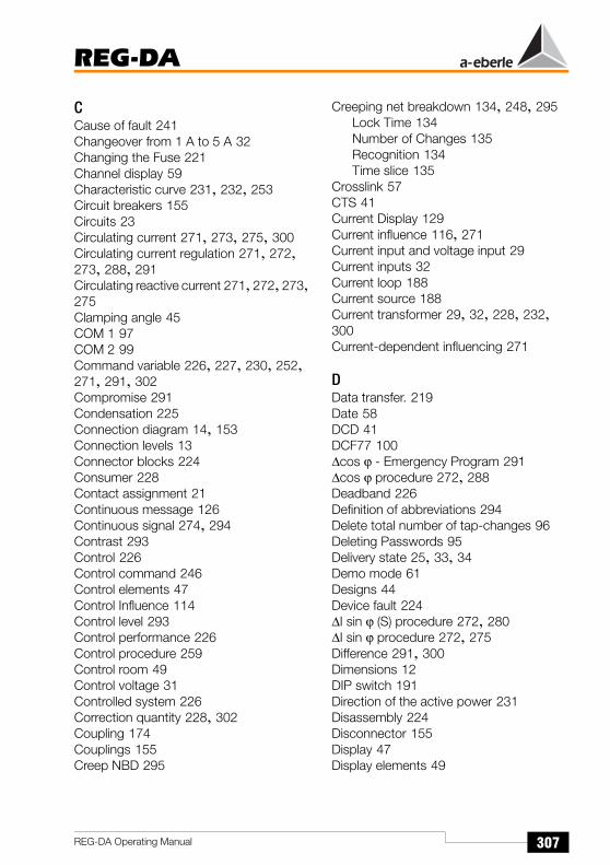
REG-DA
307REG-DA Operating Manual
CCause of fault 241Changeover from 1 A to 5 A 32Changing the Fuse 221Channel display 59Characteristic curve 231, 232, 253Circuit breakers 155Circuits 23Circulating current 271, 273, 275, 300Circulating current regulation 271, 272, 273, 288, 291Circulating reactive current 271, 272, 273, 275Clamping angle 45COM 1 97COM 2 99Command variable 226, 227, 230, 252, 271, 291, 302Compromise 291Condensation 225Connection diagram 14, 153Connection levels 13Connector blocks 224Consumer 228Contact assignment 21Continuous message 126Continuous signal 274, 294Contrast 293Control 226Control command 246Control elements 47Control Influence 114Control level 293Control performance 226Control procedure 259Control room 49Control voltage 31Controlled system 226Correction quantity 228, 302Coupling 174Couplings 155Creep NBD 295
Creeping net breakdown 134, 248, 295Lock Time 134Number of Changes 135Recognition 134Time slice 135
Crosslink 57CTS 41Current Display 129Current influence 116, 271Current input and voltage input 29Current inputs 32Current loop 188Current source 188Current transformer 29, 32, 228, 232, 300Current-dependent influencing 271
DData transfer. 219Date 58DCD 41DCF77 100∆cos ϕ - Emergency Program 291∆cos ϕ procedure 272, 288Deadband 226Definition of abbreviations 294Delete total number of tap-changes 96Deleting Passwords 95Delivery state 25, 33, 34Demo mode 61Designs 44Device fault 224∆I sin ϕ (S) procedure 272, 280∆I sin ϕ procedure 272, 275Difference 291, 300Dimensions 12DIP switch 191Direction of the active power 231Disassembly 224Disconnector 155Display 47Display elements 49
REG-DA
308 REG-DA Operating Manual
Display modes 52Monitor mode 52Recorder mode 52Regulator mode 52Statistics mode 52Transducer mode 52
Displaying the regulative deviation 239DSR 41DTR 41Dual display 55, 59
EEditing of the signal 241E-LAN 101, 267, 274, 291ELAN Err 294E-LAN error 133E-LAN error (error on bus) 294E-LAN interfaces 101E-LAN left 294E-LAN right 294ELAN-L 294ELAN-R 294E-mail 219Emergency program 291Equalisation of the tap-change positions 181Equipment 42Error detection 188Error flags 184, 277, 281Exceeding the measurement range 188External-conductor voltages 24
FFault description 224Fault signals 49, 58Faults 241Feature K1 175Feature M1 24, 29Feature M2 31, 53, 138Feeding point 57Feedrate speed 55, 60Firmware-Version 104, 154Flange plate 224Fluctuation range 238
Forward high-speed switching time 304Full load 234Fuse 9Fuse holder 30Fuse selection 223
GGeneral 91Gradient 117, 228, 233, 234, 272, 301, 303Gradient and limitation 116Group 173Group list 115, 176, 273, 275, 284Group position 177Guide value for Xwz 239
HHardware handshake 214Hexadecimal number 104Higher-level systems 99High-resistance earth contact 31High-speed backward switching 303High-speed backwards switching when overvoltage occurs 120High-speed forward switching 303High-speed forward switching when un-dervoltage occurs 120High-speed switching 246, 247, 295High-speed switching HIGHER limit signal transmitter 243High-speed switching LOWER limit signal transmitter 242High-speed switching when undervoltage/overvoltage occurs 120Hole pattern 44How to change the simulated current 148How to change the simulated phase angle 148How to change the simulated voltage 148Humidity 225Hyperbolic characteristic curve 255, 256
II Current limit 118
REG-DA
309REG-DA Operating Manual
ID data of the REG-DA Relay for Voltage Control & Transformer Monitoring 104Illogical tap-changes 186, 279, 283, 287, 290Independent (I) 173Indication 174Inh. Low 295Inhibit low limit signal transmitter 245Inhibit low time 304Input assignments 142Input channel 142Input functions 34Input quantity 241InputErr 294Inputs 25Integrating time programs 259Integrator 226, 238
JJumper 32
KKni 303Knu 303
LLabel strips 47Lamp check 58Language selection 131LCD contrast 94, 293LCD display 293LCD saver 130, 293LDC 294, 303LDC-Parameter R 116Lead sealing 12Lead-sealing wire 12LED 294LED assignments 145LEDs 47LEVEL 295Level detection 188Level-controlled activation 160Level-controlled switching 296Life contact 33
Limit base 135Limit signal 241limit signal 241Limit signal <I 244Limit signal >I 244Limit signal trigger 242Limit value 300Limit value violation 241Limitation 114, 117, 232, 303Limitation of the current-dependent set-point influencing 117Limit-value transmitter <U 244Limit-value transmitter >U 243Line drop compensation 229, 294, 303Linear characteristic line 258Load 228Load changes 260Load current 227, 271, 300Load point 229, 230Load situation 260Loading procedure 261Lock control command 33Lock duration 249LOGBOOK memory 107Loop resistance 270Lower part of the housing 30
MmA inputs 42mA outputs 42Maintenance 220Maintenance and repair works 10Manual/Automatic 127
Bistable switching behaviour 127Flip/Flop switching behaviour 127
Master (M) 173Master-Slave Independent 173Master-Slave procedure 173, 272, 284Maximum tap difference 136Maximum tap-change difference 250Maximum time TC in operation 126, 246Measurement input 189Measurement quantity 249Measurement transformers 292Measurement value simulation 146

REG-DA
310 REG-DA Operating Manual
Measuring circuit 223Membrane keypad 47Memory 55Menu selection 51Minimisation of the circulating reactive cur-rent 273, 274MMU display 59Monitoring algorithm 181Monitoring of extreme operating values 241Monitoring tasks 241Monitoring the tap-changer 250Motor circuit breaker 144Mounting bars 44Mounting holes 44Mounting on standard mounting rails 46Mounting panel 45Mounting surface 44MSI 173MSI_Ind 177MSI_Ma 177MSI_Sl 177Multimaster 267Multimaster structure 270
NNet-cosϕ 115Network 271Network conditions 29Network voltage 226, 291No tap-change 186, 278, 283, 286, 290No. of switching operations 226, 238Nominal isolation voltage 23Nominal power 272, 275, 280Nominal power of the transformer 115, 272Nominal transformation 292Nominal transformation of measurement transformers 292Nominal transformation ratio of the voltage transformers 292Nominal translation of current transformers 292Nominal value of the gradient 232Nominal voltage 232, 234
Non-fused earthed conductor 9Number of tap-change positions 176
OOFF 294Oil temperature 42Open ring 267Operating in parallel 150, 153, 173, 271, 274Operating panel 269Operating personnel 49Operating Principle 51Operating principle 51Operating the transformers in parallel 272Oscillations 276, 281Output 226Output level 267Outputs 25Overvoltage 118, 303Overvoltage time 304
PPAN-D 104, 217PAN-D Voltage Monitoring Unit 104PAN-D voltage monitoring unit 104Panel-mounting version 45ParaGramer 57Parallel operation 291Parallel program 113, 136, 294Parallel program activation 132Parallel regulation program 272Parallel transformer regulation 113Parameter for parallel program 114Parameter menus 114Parameterisation of the REG-DA Relay for Voltage Control & Transformer Monitoring 108Parameterisation panel 49Parameters 303ParErr 184, 295Par-Prog 294PASSWORD 94Password 12, 95Password request 95

REG-DA
311REG-DA Operating Manual
Past values 55People-process communication (MPK) 47Permissible circulating currents 273Permissible Icirc 276Permissible regulative deviation 52, 109, 238, 239Phase voltage 31PhaseFail 295Plausibility 242Plug-in module 12Plug-in shoe 30Position of the deadband 284Potential-free relay 33Prerequisites for MSI operation 175Primary side 233Primary value 111Primary voltage 227, 260Printed nameplate 30Procedure for determining measurement values 255PROG 295Programming and parameterisation soft-ware 11Programs 113Progress bar 261Protective earth 30PT 100 42Pulse-controlled activation 160
QQuasi-analogue scale 54Quick 295
Rr.m.s. value 229, 301Rating factor 252, 253Reactance 229Reaction delay 246, 255Reaction time 253Reactive component 273Reactive component of the load current 276Reactive current 275, 276, 281, 288, 301Reactive current difference 288
Record 267Recorder display 55Recorder mode 54Reference value 302Reference value for the limit values 245Reflections 269REG-5A/E 256REG-D current consumption 223REG-L 242Regulating quantity 238, 302Regulation behaviour 109Regulation behaviour time factor 109Regulation criteria 271Regulation difference 238, 302Regulation program 272, 274, 275Regulation result 288regulative deviation 52, 238, 249, 252, 302, 303Regulative deviation Xw 226Regulator inhibit low when undervoltage occurs 121Regulator mode large display 130Relative humidity 225Relative Limits 245Relay assignments 143Relay outputs 33relay outputs 301Remote control command 48Repeater 267Replacement device 224Replacement fuse 30Resetting Fault Signals 58Resetting the measured value memory 95Resetting the tap-counter 96Resistance input 187Resistance measurement equipment 187RI 41Rotating memory 107RTS 41Running time exceeded 294Running time of the motor drive 126RXD 41
SSafety class 30

REG-DA
312 REG-DA Operating Manual
Safety regulations 9Scale section 61Scope of delivery 11Secondary factor 292Secondary side 233Secondary value 111Secondary winding 301Selecting the regulation procedure 150Selection of the operating mode 180Self-conduction of the operation mode 129
WITH 129WITHOUT 129
Set of curves 257Setpoint adjustment 133Setpoint deviation 52Setpoint value 52, 227setpoint value 111, 133, 226, 233, 234, 296, 303Setpoint value 1 295Setpoint value 2 296Setpoint value 3 296Setpoint value 4 296Setpoint value correction 239Setpoint value reduction 234Setting inhibit low if I 136Setting values 234Settings recommendation 263Setup menu 58Short circuit voltage 272, 275, 276, 280, 301Signal level 102Signal-Ground 41Simulated current 148Simulated phase angle 148Simulated tap-change 149Simulated voltage 148Simulation mode 147Simulation time 147Simulator for the quantities U, I, and j 147Single-phase connection 29Slave (S) 173Small voltage 23Small voltage deviations 252
Socket connectorsSocket connector 1 (binary outputs BO) 33
SP-1 295SP-2 296SP2Level 296SP-3 296SP-4 296SP-decr. 296Special version 32SP-incr. 296Spur line lengths 270Standard regulating functions 24Standard value 301Standby mode 174Standstill 247, 295, 303Start bootstrap loader 215Station ID 91Station name 92Statistics mode 56Status 104Storage 221, 225Sum current 271, 291Supply voltage 33Switching delay 241, 253
<U 122> I, < I limit value 122>U 121High-speed backward switching 123High-speed forward switching 123Standstill 124Tripping 122
Switching difference 241Switching hysteresis 241Switching operations 155Switching problems 181Switching status 163Switching statuses 57, 155Switching to a setpoint value 227, 294Symbols 300Synchronising the time 100System identification 104

REG-DA
313REG-DA Operating Manual
TTap-change 52, 128, 239, 271, 273
OFF 128Tap-change adjustment 155Tap-change command 260Tap-change difference 273Tap-change equalisation procedure 173Tap-change operation 259Tap-change procedure 226Tap-change signal 279, 283, 287, 290Tap-change voltage 226Tap-changer 226, 241, 246, 247, 250Tap-changer drives 246Tap-changer in operation time 246Tap-changer running time 294Tap-changes in the wrong direction 185, 278, 283, 286, 289Tap-changes under load 56Tap-changing transformer 52, 227TapErr 184, 295TC. i. Op 294TC-Err+ 294TC-Err. 294Technical data 12Telegram length 267Temperature range 225Temporary message 126Temporary signal 294Terminal diagram 25Terminal voltage 271Terminate 102Terminating resistance 269Terminating resistor 101Three-tap-change regulator 226Time 58, 93Time > I 304Time axis 55Time behaviour 109, 110, 226Time factor 109, 253, 266, 304Time program 110Time range 55Time reference line 58Time search 59Time sequence 246Tolerance band 55, 238, 252
Topology 269Trans 296Transducer mode 53Transformer 226, 234, 239Transformer configuration 153Transformer group list 273, 274Transformer monitoring 42Transformer mounting 138
Current 140Current (conversion 1 A / 5 A) 140Current transformer mounting ratio 141Voltage 138Voltage transformer ratio 140
Transformer mounting ratio 301Transformer tap-change position 239Transit channel 296Transmission lengths 102Transmission line 269, 270Transmission rate 267Trend memory 110, 261Trigger time 304Triple-wound application 32, 294Triple-wound applications 24Tripping 119, 294, 303Trouble-shooting 184Twin connector block 30TXD 41Type of characteristic line 233Type of voltage 31Types of lines 269Types of power supply units 30
UUf/I characteristic line 301Undervoltage 117, 303Undervoltage side 271Undervoltage time 304Unit time 259Up/down 294Update of the operating software 214User 94

REG-DA
314 REG-DA Operating Manual
VVariable command variable 227, 228Voltage band 259Voltage deviation 259Voltage difference 229Voltage dip 31Voltage drop 226, 227, 228, 229, 230, 301Voltage measurement input 188Voltage pointer 230Voltage regulation 271, 273Voltage return 129Voltage stability 274Voltage value 58Voltage-time diagram 58
WWall-mounting version 44Warnings and Notes 9Weak load 234WinREG 11, 61, 92, 146, 177, 267
ZZero modem cable 214


![A New Paradigm for the Sociology of Knowledge [Eberle]](https://img.pdfslide.us/doc/110x75/577cbfc41a28aba7118e0a17/a-new-paradigm-for-the-sociology-of-knowledge-eberle.jpg)