Embed Size (px)
Citation preview
Reel Rain Traveler Irrigation
B1025, 1030
3rd Edition, Serial # 370600
April 2005 MAN081
©2005

Reel Rain Traveler Irrigation Series B1025 and B1030 are manufactured by Amadas Industries:
You can find us on the Web at:
www.amadas.com
or e-mail us at: [email protected]
P.O. Box 1833 Suffolk, VA 23439
(mailing)
1100 Holland Road Suffolk, VA 23434
(shipping)
(757) 539-0231 (Phone) (757) 934-3264 (FAX)
P.O. Box 3687 Albany, GA 31701
(mailing)
1701 South Slappey Blvd. Albany, GA 31706
(shipping)
(229) 439-2217 (Phone) (229) 439-9343 (FAX)
Reel Rain B10 Series Introduction
MAN081 6/3/05 i
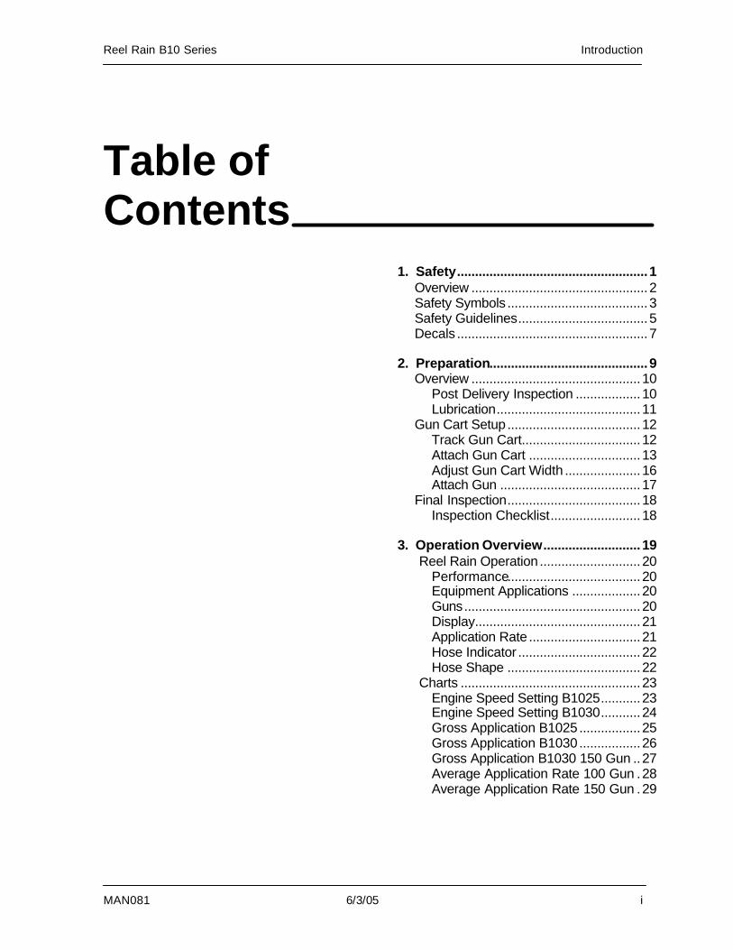
Table of Contents
1. Safety.....................................................1 Overview .................................................2 Safety Symbols .......................................3 Safety Guidelines....................................5 Decals .....................................................7 2. Preparation............................................9 Overview ...............................................10 Post Delivery Inspection ..................10 Lubrication........................................11 Gun Cart Setup.....................................12 Track Gun Cart.................................12 Attach Gun Cart ...............................13 Adjust Gun Cart Width .....................16 Attach Gun .......................................17 Final Inspection.....................................18 Inspection Checklist.........................18 3. Operation Overview...........................19
Reel Rain Operation ............................20 Performance.....................................20 Equipment Applications ...................20 Guns.................................................20 Display..............................................21 Application Rate ...............................21 Hose Indicator ..................................22 Hose Shape .....................................22 Charts ..................................................23 Engine Speed Setting B1025...........23 Engine Speed Setting B1030...........24 Gross Application B1025.................25 Gross Application B1030.................26 Gross Application B1030 150 Gun ..27 Average Application Rate 100 Gun .28 Average Application Rate 150 Gun .29
Introduction Reel Rain B10 Series
ii 6/3/05 MAN081
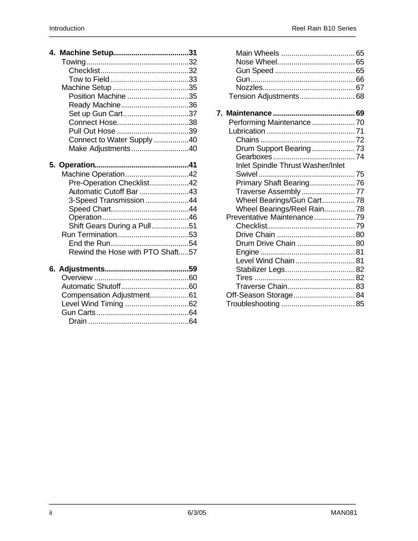
4. Machine Setup.....................................31 Towing..................................................32 Checklist...........................................32 Tow to Field ......................................33 Machine Setup .....................................35 Position Machine ..............................35 Ready Machine.................................36 Set up Gun Cart................................37 Connect Hose...................................38 Pull Out Hose ...................................39 Connect to Water Supply .................40 Make Adjustments ............................40
5. Operation..............................................41 Machine Operation...............................42 Pre-Operation Checklist...................42 Automatic Cutoff Bar ........................43 3-Speed Transmission .....................44 Speed Chart......................................44 Operation ..........................................46 Shift Gears During a Pull ..................51 Run Termination...................................53 End the Run......................................54 Rewind the Hose with PTO Shaft.....57
6. Adjustments.........................................59 Overview ..............................................60 Automatic Shutoff.................................60 Compensation Adjustment...................61 Level Wind Timing ...............................62 Gun Carts .............................................64 Drain .................................................64
Main Wheels ....................................65 Nose Wheel......................................65 Gun Speed .......................................65 Gun...................................................66 Nozzles.............................................67 Tension Adjustments...........................68
7. Maintenance........................................69 Performing Maintenance .....................70 Lubrication ...........................................71 Chains ..............................................72 Drum Support Bearing .....................73 Gearboxes........................................74
Inlet Spindle Thrust Washer/Inlet Swivel ...............................................75 Primary Shaft Bearing......................76 Traverse Assembly ..........................77 Wheel Bearings/Gun Cart................78 Wheel Bearings/Reel Rain...............78
Preventative Maintenance....................79 Checklist...........................................79 Drive Chain ......................................80 Drum Drive Chain ............................80 Engine ..............................................81 Level Wind Chain .............................81 Stabilizer Legs..................................82 Tires .................................................82 Traverse Chain.................................83 Off-Season Storage..............................84 Troubleshooting ....................................85

Reel Rain B10 Series Introduction
MAN081 6/3/05 iii
Welcome To AMADAS Industries
With origins dating back to 1963, AMADAS Industries and its predecessors have a long history of providing high quality, reliable and innovative equipment for the farming industry. AMADAS equipment is currently at work throughout the United States and in many other countries. This equipment ranges from the Magnum Fource Peanut Combine, Tree Bark Processing and Packaging Machinery, Hi-Speed Cotton Stalk Puller/Chopper to the Reel Rain Traveler Irrigation Systems.
Introduction Reel Rain B10 Series
iv 6/3/05 MAN081
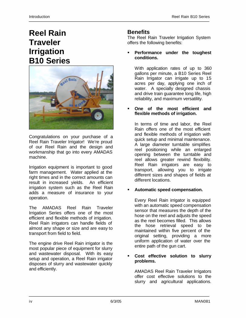
Reel Rain Traveler Irrigation B10 Series
Congratulations on your purchase of a Reel Rain Traveler Irrigator! We’re proud of our Reel Rain and the design and workmanship that go into every AMADAS machine. Irrigation equipment is important to good farm management. Water applied at the right times and in the correct amounts can result in increased yields. An efficient irrigation system such as the Reel Rain adds a measure of insurance to your operation. The AMADAS Reel Rain Traveler Irrigation Series offers one of the most efficient and flexible methods of irrigation. Reel Rain irrigators can handle fields of almost any shape or size and are easy to transport from field to field. The engine drive Reel Rain irrigator is the most popular piece of equipment for slurry and wastewater disposal. With its easy setup and operation, a Reel Rain irrigator disposes of slurry and wastewater quickly and efficiently.
Benefits The Reel Rain Traveler Irrigation System offers the following benefits: § Performance under the toughest
conditions.
With application rates of up to 360 gallons per minute, a B10 Series Reel Rain Irrigator can irrigate up to 15 acres per day, applying one inch of water. A specially designed chassis and drive train guarantee long life, high reliability, and maximum versatility.
§ One of the most efficient and flexible methods of irrigation.
In terms of time and labor, the Reel Rain offers one of the most efficient and flexible methods of irrigation with quick setup and minimal maintenance. A large diameter turntable simplifies reel positioning while an enlarged opening between the turntable and reel allows greater rewind flexibility. Reel Rain irrigators are easy to transport, allowing you to irrigate different sizes and shapes of fields at different locations.
§ Automatic speed compensation.
Every Reel Rain irrigator is equipped with an automatic speed compensation sensor that measures the depth of the hose on the reel and adjusts the speed as the reel becomes filled. This allows the hose retrieval speed to be maintained within five percent of the original setting, providing a more uniform application of water over the entire path of the gun cart.
§ Cost effective solution to slurry problems.
AMADAS Reel Rain Traveler Irrigators offer cost effective solutions to the slurry and agricultural applications.
Reel Rain B10 Series Introduction
MAN081 6/3/05 v
When combined with a chopper pump, the Reel Rain can process slurry with a solids content of up to 7%.
§ Three-speed Gearbox.
The Reel Rain B1025 and B1030 come standard with a three-speed gearbox that eliminates the need for multiple belts and pulleys, while providing more accurate control over application rates.
Features The Reel Rain B1025 and B1030 come standard with the following features: § 4HP gas engine § Heavy duty chassis and drive train § Heavy duty medium density
polyethylene hose § 3-speed gearbox
§ Large diameter inlet plumbing for lower friction loss
§ Nelson 100 gun, Nelson 150 gun available for B1030
§ Mechanical hose guide § Miss wrap sensor § Automatic hose retrieval stop § Automatic reel speed compensator § Standard galvanized gun cart § Gun cart lift § Throw down stabilizer legs § PTO rewind with hand crank § Pressure gauge § Quick couple infeed hose connectors Optional Features The following are options available for the B1025 and B1030: § Optional PTO shaft § Gun cart weight kit § 5-gallon fuel tank
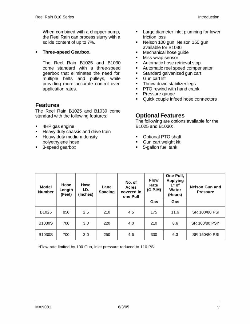
Flow Rate
(G.P.M)
One Pull, Applying
1” of Water
(Hours)
Model Number
Hose Length (Feet)
Hose I.D.
(Inches)
Lane Spacing
No. of Acres
covered in one Pull
Gas Gas
Nelson Gun and Pressure
B1025 850 2.5 210 4.5 175 11.6 SR 100/80 PSI
B1030S 700 3.0 220 4.0 210 8.6 SR 100/80 PSI*
B1030S 700 3.0 250 4.6 330 6.3 SR 150/80 PSI
*Flow rate limited by 100 Gun, inlet pressure reduced to 110 PSI

Reel Rain B10 Series Safety
MAN081 6/3/05 1
1. Safety
Overview....................................................2 Safety Symbols..........................................3 Safety Guidelines ......................................5 Decals........................................................7
Safety Reel Rain B10 Series
2 6/3/05 MAN081
Overview Safety is the responsibility of everyone. Although safety features are incorporated into the machine and dangerous areas clearly marked, ultimately, careful operation is the best prevention against accidents. To reduce the risk of accidents, please read thoroughly and follow the safety instructions and messages included in this manual and on the machine. Safety Symbols Used The three safety symbols used on the machine and in this manual are shown below. The following section explains each of these symbols in detail.
DANGER
WARNING
CAUTION Please familiarize yourself with each symbol and its meaning. It is crucial to your safety and the safety of others that you follow the safety precautions indicated by these symbols. Protective Devices Protective devices and shields have been installed to protect the user from hazards. Never remove, tamper with, or modify guards or shields. To do so could result in serious personal injury or death. If it is necessary to remove a shield to perform maintenance, it is essential that the shield be replaced prior to operating the Reel Rain.
Careful Lifting Please follow safe lifting procedures when installing or removing any equipment. Use a second person as a helper when indicated by the weight of an item.
Reel Rain B10 Series Safety
MAN081 6/3/05 3
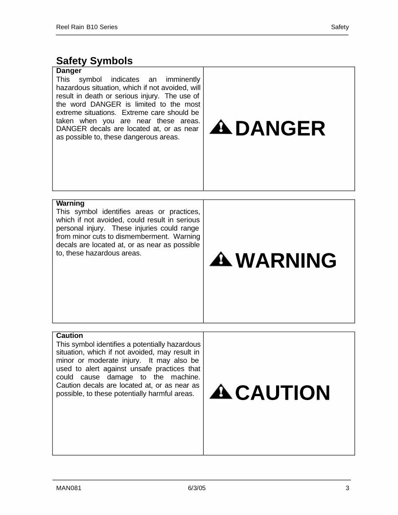
Safety Symbols Danger This symbol indicates an imminently hazardous situation, which if not avoided, will result in death or serious injury. The use of the word DANGER is limited to the most extreme situations. Extreme care should be taken when you are near these areas. DANGER decals are located at, or as near as possible to, these dangerous areas.
DANGER
Warning This symbol identifies areas or practices, which if not avoided, could result in serious personal injury. These injuries could range from minor cuts to dismemberment. Warning decals are located at, or as near as possible to, these hazardous areas.
WARNING
Caution This symbol identifies a potentially hazardous situation, which if not avoided, may result in minor or moderate injury. It may also be used to alert against unsafe practices that could cause damage to the machine. Caution decals are located at, or as near as possible, to these potentially harmful areas.
CAUTION
Safety Reel Rain B10 Series
4 6/3/05 MAN081
Safety Alert Symbol This symbol alerts you to possible hazards. Follow the recommended precautions and safe operating procedures. If you have any questions, please contact your dealer or the manufacturer.
Safety Instructions Safety features have been designed into the machine with hazardous areas marked. Please read and follow the instructions in this manual prior to operating, maintaining, or servicing this machine. Notes Throughout the manual, information that needs to be emphasized is set apart with either a “NOTE!” or “IMPORTANT!” heading. Please be sure to read this information carefully, as it usually indicates a situation that could cause machine damage.
Example:
NOTE! The engine has an automatic shutoff that engages if the oil level is too low. Refer to the Honda Manual for more information on the engine.
Reel Rain B10 Series Safety
MAN081 6/3/05 5
Safety Guidelines Many accidents can be prevented by knowing about safety. Prevent hazards by reading the safety warnings in this manual. Alert others to potential hazards. Remember all machinery can be dangerous if used incorrectly. Please operate carefully. Safety is only a word until it is put into practice. When operating this machine: § Do NOT climb or ride on this machine
at any time. § Do NOT let anyone stand between the
machine and the gun cart. § Make sure everyone is clear of the
machine prior to and during operation. § Keep all shields in place. § Keep fingers, feet, and loose clothing
away from moving parts. § Do NOT stand near high pressure
water lines while pressurizing the system.
§ Do NOT operate the machine with an inlet pressure exceeding 150 PSI.
§ Lower the stabilizer legs and jack prior
to towing out the hose. § Periodically check all nuts and bolts for
tightness. § Stand clear of the gun while in
operation. § Do NOT stand in front of the gun
during operation. The high velocity water exiting the gun can cause injury.
When transporting this machine: § ALWAYS make sure the drum reel is
lined up parallel with the chassis before moving the irrigator.
§ ALWAYS make sure the turntable is
locked with the hitch pin before moving the irrigator.
§ ALWAYS use safety chains when
towing the irrigator. § ALWAYS hook the loose end of each
gun lift chain into the opening from which the chain is hung.
§ Do NOT tow in excess of 20 MPH
when empty or 3 MPH when hoses are full of water.
§ Make sure the machine is level when it
is towed.
Safety Reel Rain B10 Series
6 6/3/05 MAN081
When performing maintenance on this machine: § Do NOT make adjustments or attempt
any maintenance while the machine is in operation.
§ ALWAYS engage the reel brake before
attempting any maintenance or adjustments.
§ Do NOT change gun nozzles while
there is water pressure in the system.
Reel Rain B10 Series Safety
MAN081 6/3/05 7
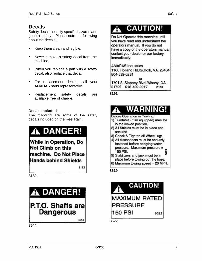
Decals Safety decals identify specific hazards and general safety. Please note the following about the decals: § Keep them clean and legible. § Never remove a safety decal from the
machine. § When you replace a part with a safety
decal, also replace that decal. § For replacement decals, call your
AMADAS parts representative. § Replacement safety decals are
available free of charge. Decals Included The following are some of the safety decals included on the Reel Rain:
8182
8544
8191
8619
8622

Safety Reel Rain B10 Series
8 6/3/05 MAN081
NOTES:
Reel Rain B10 Series Preparation
MAN081 6/3/05 9
2. Preparation
Overview..................................................10 Post Delivery Inspection ......................10 Lubrication ...........................................11
Gun Cart Setup........................................12 Track Gun Cart ....................................12 Attach Gun Cart ...................................13 Adjust Gun Cart Width.........................16 Attach Gun ...........................................17
Final Inspection .......................................18 Inspection Checklist.............................18
Preparation Reel Rain B10 Series
10 6/3/05 MAN081
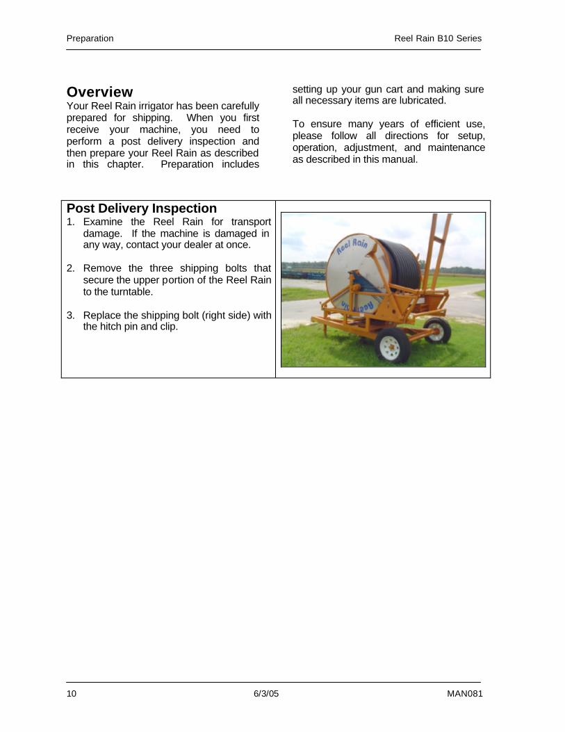
Overview Your Reel Rain irrigator has been carefully prepared for shipping. When you first receive your machine, you need to perform a post delivery inspection and then prepare your Reel Rain as described in this chapter. Preparation includes
setting up your gun cart and making sure all necessary items are lubricated. To ensure many years of efficient use, please follow all directions for setup, operation, adjustment, and maintenance as described in this manual.
Post Delivery Inspection 1. Examine the Reel Rain for transport
damage. If the machine is damaged in any way, contact your dealer at once.
2. Remove the three shipping bolts that
secure the upper portion of the Reel Rain to the turntable.
3. Replace the shipping bolt (right side) with
the hitch pin and clip.
Reel Rain B10 Series Preparation
MAN081 6/3/05 11
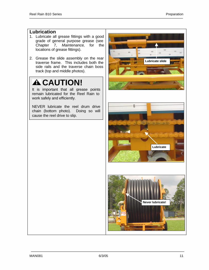
Lubrication 1. Lubricate all grease fittings with a good
grade of general purpose grease (see Chapter 7, Maintenance, for the locations of grease fittings).
2. Grease the slide assembly on the rear
traverse frame. This includes both the side rails and the traverse chain boss track (top and middle photos).
CAUTION! It is important that all grease points remain lubricated for the Reel Rain to work safely and efficiently. NEVER lubricate the reel drum drive chain (bottom photo). Doing so will cause the reel drive to slip.
Lubricate slide
Lubricate
Never lubricate!
Preparation Reel Rain B10 Series
12 6/3/05 MAN081
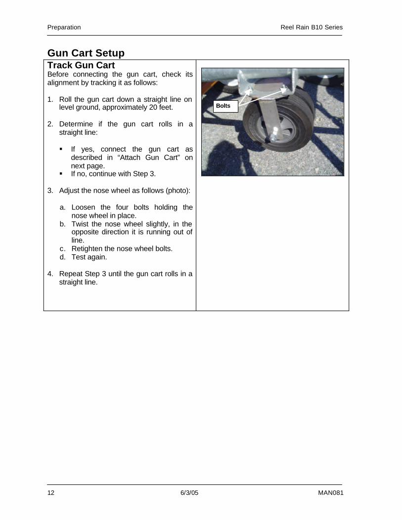
Gun Cart Setup Track Gun Cart Before connecting the gun cart, check its alignment by tracking it as follows: 1. Roll the gun cart down a straight line on
level ground, approximately 20 feet. 2. Determine if the gun cart rolls in a
straight line: § If yes, connect the gun cart as
described in “Attach Gun Cart” on next page.
§ If no, continue with Step 3. 3. Adjust the nose wheel as follows (photo):
a. Loosen the four bolts holding the nose wheel in place.
b. Twist the nose wheel slightly, in the opposite direction it is running out of line.
c. Retighten the nose wheel bolts. d. Test again.
4. Repeat Step 3 until the gun cart rolls in a
straight line.
Bolts
Reel Rain B10 Series Preparation
MAN081 6/3/05 13
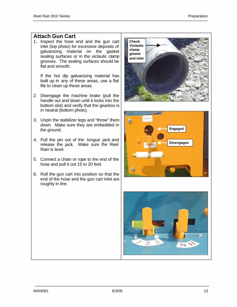
Attach Gun Cart 1. Inspect the hose end and the gun cart
inlet (top photo) for excessive deposits of galvanizing material on the gasket sealing surfaces or in the victaulic clamp grooves. The sealing surfaces should be flat and smooth.
If the hot dip galvanizing material has built up in any of these areas, use a flat file to clean up these areas.
2. Disengage the machine brake (pull the handle out and down until it locks into the bottom slot) and verify that the gearbox is in neutral (bottom photo).
3. Unpin the stabilizer legs and “throw” them
down. Make sure they are embedded in the ground.
4. Pull the pin out of the tongue jack and
release the jack. Make sure the Reel Rain is level.
5. Connect a chain or rope to the end of the
hose and pull it out 15 to 20 feet. 6. Roll the gun cart into position so that the
end of the hose and the gun cart inlet are roughly in line.
Disengaged
Engaged
Check Victaulic clamp groove and inlet
Preparation Reel Rain B10 Series
14 6/3/05 MAN081
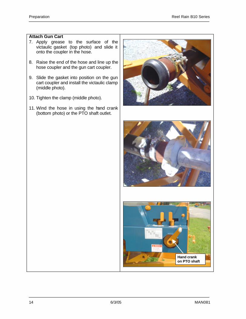
Attach Gun Cart 7. Apply grease to the surface of the
victaulic gasket (top photo) and slide it onto the coupler in the hose.
8. Raise the end of the hose and line up the
hose coupler and the gun cart coupler. 9. Slide the gasket into position on the gun
cart coupler and install the victaulic clamp (middle photo).
10. Tighten the clamp (middle photo). 11. Wind the hose in using the hand crank
(bottom photo) or the PTO shaft outlet.
Hand crank on PTO shaft
Reel Rain B10 Series Preparation
MAN081 6/3/05 15
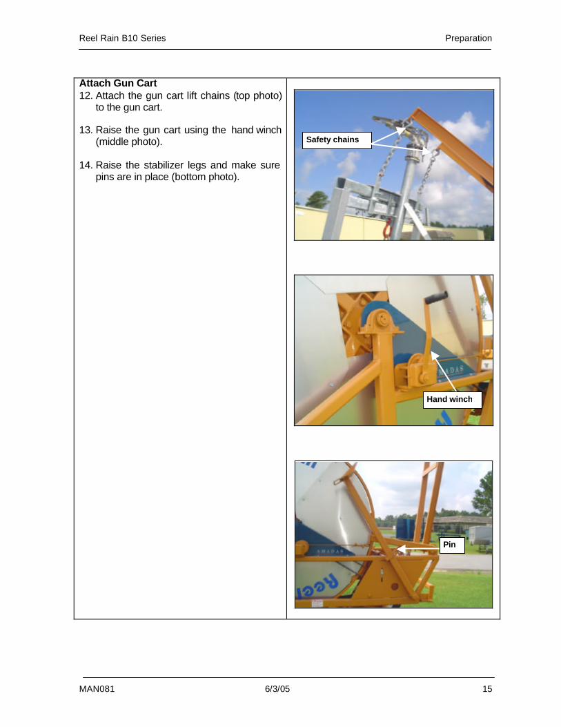
Attach Gun Cart 12. Attach the gun cart lift chains (top photo)
to the gun cart. 13. Raise the gun cart using the hand winch
(middle photo). 14. Raise the stabilizer legs and make sure
pins are in place (bottom photo).
Safety chains
Hand winch
Pin
Preparation Reel Rain B10 Series
16 6/3/05 MAN081
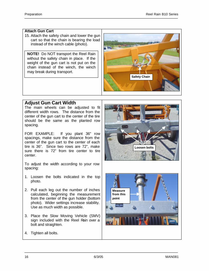
Attach Gun Cart 15. Attach the safety chain and lower the gun
cart so that the chain is bearing the load instead of the winch cable (photo).
Adjust Gun Cart Width The main wheels can be adjusted to fit different width rows. The distance from the center of the gun cart to the center of the tire should be the same as the planted row spacing. FOR EXAMPLE: If you plant 36” row spacings, make sure the distance from the center of the gun cart to the center of each tire is 36”. Since two rows are 72”, make sure there is 72” from tire center to tire center. To adjust the width according to your row spacing: 1. Loosen the bolts indicated in the top
photo. 2. Pull each leg out the number of inches
calculated, beginning the measurement from the center of the gun holder (bottom photo). Wider settings increase stability. Use as much width as possible.
3. Place the Slow Moving Vehicle (SMV)
sign included with the Reel Rain over a bolt and straighten.
4. Tighten all bolts.
Safety Chain
NOTE! Do NOT transport the Reel Rain without the safety chain in place. If the weight of the gun cart is not put on the chain instead of the winch, the winch may break during transport.
Loosen bolts
Measure from this point
Reel Rain B10 Series Preparation
MAN081 6/3/05 17
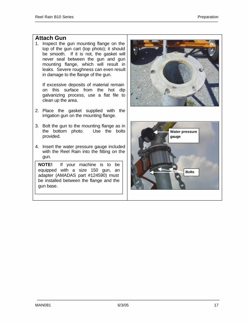
Attach Gun 1. Inspect the gun mounting flange on the
top of the gun cart (top photo); it should be smooth. If it is not, the gasket will never seal between the gun and gun mounting flange, which will result in leaks. Severe roughness can even result in damage to the flange of the gun.
If excessive deposits of material remain on this surface from the hot dip galvanizing process, use a flat file to clean up the area.
2. Place the gasket supplied with the irrigation gun on the mounting flange.
3. Bolt the gun to the mounting flange as in
the bottom photo. Use the bolts provided.
4. Insert the water pressure gauge included
with the Reel Rain into the fitting on the gun.
Bolts
Water pressure gauge
NOTE! If your machine is to be equipped with a size 150 gun, an adapter (AMADAS part #124590) must be installed between the flange and the gun base.
Preparation Reel Rain B10 Series
18 6/3/05 MAN081
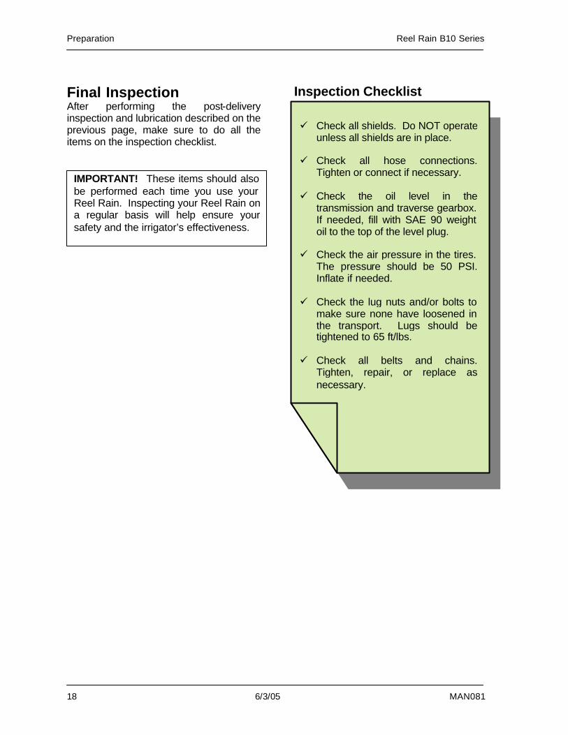
Final Inspection After performing the post-delivery inspection and lubrication described on the previous page, make sure to do all the items on the inspection checklist.
Inspection Checklist
IMPORTANT! These items should also be performed each time you use your Reel Rain. Inspecting your Reel Rain on a regular basis will help ensure your safety and the irrigator’s effectiveness.
ü Check all shields. Do NOT operate unless all shields are in place.
ü Check all hose connections.
Tighten or connect if necessary. ü Check the oil level in the
transmission and traverse gearbox. If needed, fill with SAE 90 weight oil to the top of the level plug.
ü Check the air pressure in the tires.
The pressure should be 50 PSI. Inflate if needed.
ü Check the lug nuts and/or bolts to
make sure none have loosened in the transport. Lugs should be tightened to 65 ft/lbs.
ü Check all belts and chains.
Tighten, repair, or replace as necessary.
Reel Rain B10 Series Operation Overview
MAN081 6/3/05 19
3. Operation Overview
Reel Rain Operation ................................20
Performance........................................20 Equipment Applications .......................20 Guns.....................................................20 Display .................................................21 Application Rate...................................21 Hose Indicator......................................22 Hose Shape .........................................22
Charts ......................................................23 Engine Speed Setting B1025 ..............23 Engine Speed Settings for B1030 .......24 Gross Application B1025.....................25 Gross Application B1030.....................26 Gross Application Rate 1030 150 Gun27 Average Application Rate 100 Gun.....28 Average Application Rate 150 Gun.....29
Operation Overview Reel Rain B10 Series
20 6/3/05 MAN081
Reel Rain Operation AMADAS Reel Rains are hard hose traveler irrigators. They have been designed with the operator in mind to give you what you need most from a hard hose traveler: quick setup, simple operation, and low maintenance. With the Reel Rain B10 series, you achieve irrigation rates for 1” of water of up to 15 acres per day. Your Reel Rain applies a uniform application of water over your crops at a rate and amount that you determine. Included in this chapter are charts to help you determine the best settings to suit your needs. Always be careful when you tow the irrigator. Hard hose travelers have an inherently high center of gravity, which can make them unstable on hillsides and in sharp turns. While the Reel Rain’s design has minimized this problem, the heavy weight of the machine when filled with water needs to be taken into account. Chapter 4, Machine Setup, contains more information on safely transporting the Reel Rain. Special attention has been paid to the convenience of operating the Reel Rain, but not at the expense of safety. Please review Chapter 1, Safety, for safety information prior to operating the Reel Rain. Performance The Reel Rain operates as described in the following steps. Step 1. The Reel Rain consists of a polyethylene hose, attached on one end to a water supply, wound around a reel drum, with the other end of the hose connected to a gun cart. Before irrigating, the gun cart is towed away from the Reel Rain, causing the hose to unwind.
Step 2. Powered by the engine, the drum rotates to reel the hose back in, pulling the gun cart along the hose’s path. As the hose and gun cart are reeled in, the gun applies a uniform application over the entire lane the gun cart travels. Step 3. Once the gun cart is reeled back to the drum, it strikes a cutoff bar, which automatically shuts off the engine and stops the drum. The Reel Rain continues to spray water. NOTE! The faster the hose is rewound, the quicker the machine can be moved to the next lane. However, a low retrieval speed is necessary for a high water application rate, so the amount of water needed determines the application rate. To calculate the correct speed for your needs, please refer to the chart guidelines included in this chapter. Equipment Applications The Reel Rain Traveler Irrigation System can be used to pump clear water, waste water, gray water, or slurry. Always flush out the Reel Rain after use when pumping waste. Guns The recommended gun to use for pumping waste water and slurry is an irrigation gun with a taper bore nozzle. The taper bore nozzle is also recommended for use with low pressure applications to assist in even disbursement.
Reel Rain B10 Series Operation Overview
MAN081 6/3/05 21
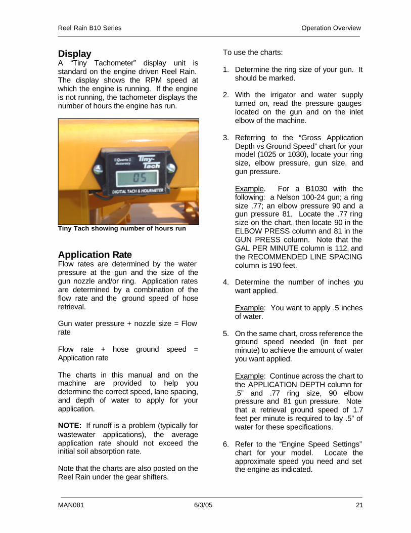
Display A “Tiny Tachometer” display unit is standard on the engine driven Reel Rain. The display shows the RPM speed at which the engine is running. If the engine is not running, the tachometer displays the number of hours the engine has run.
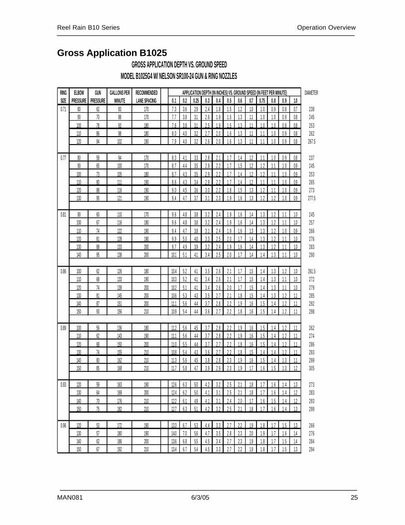
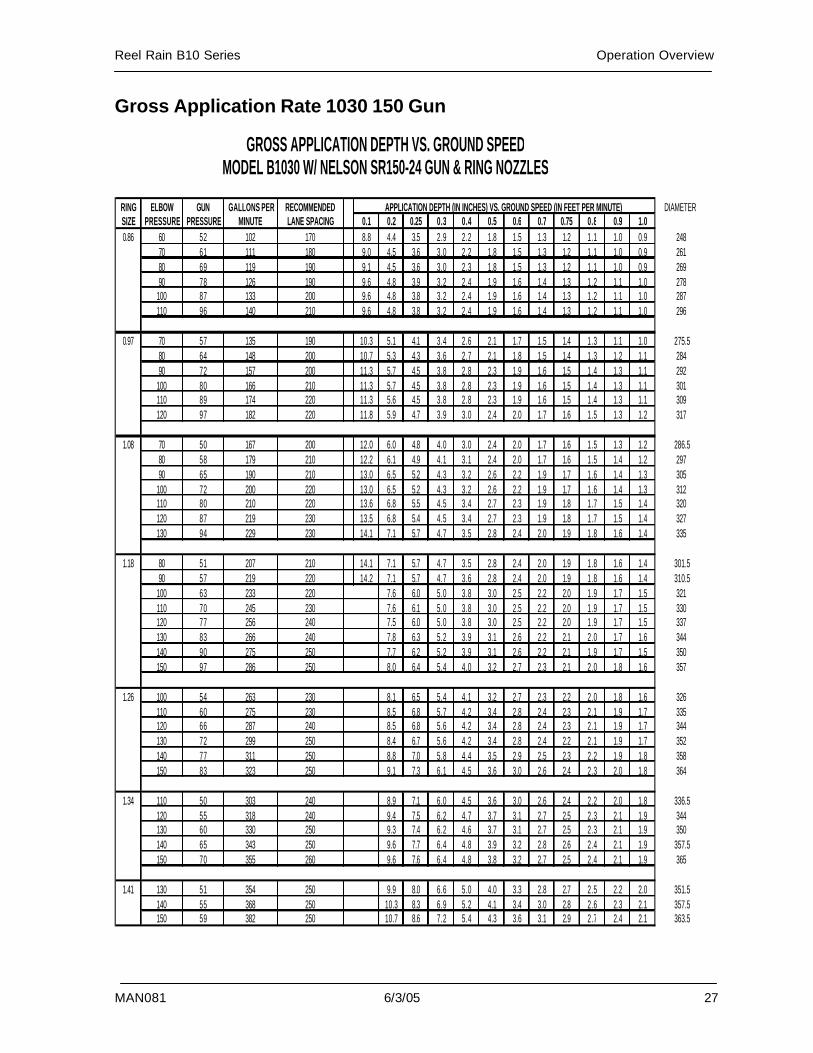
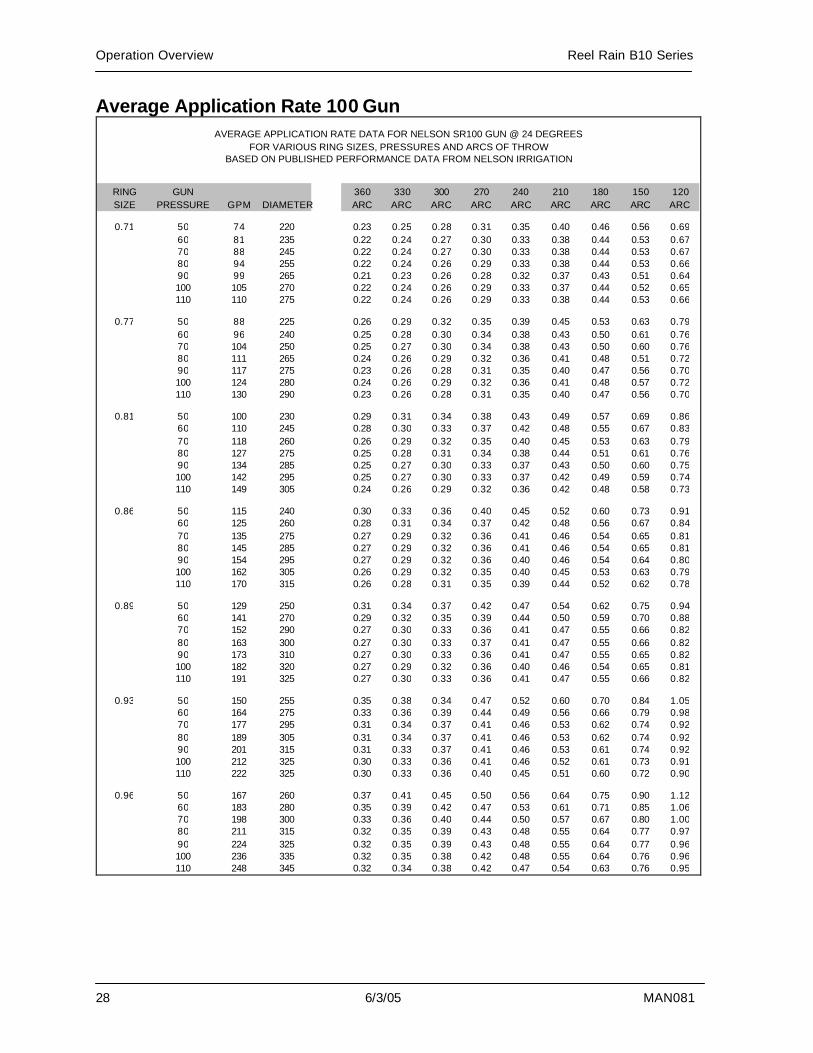
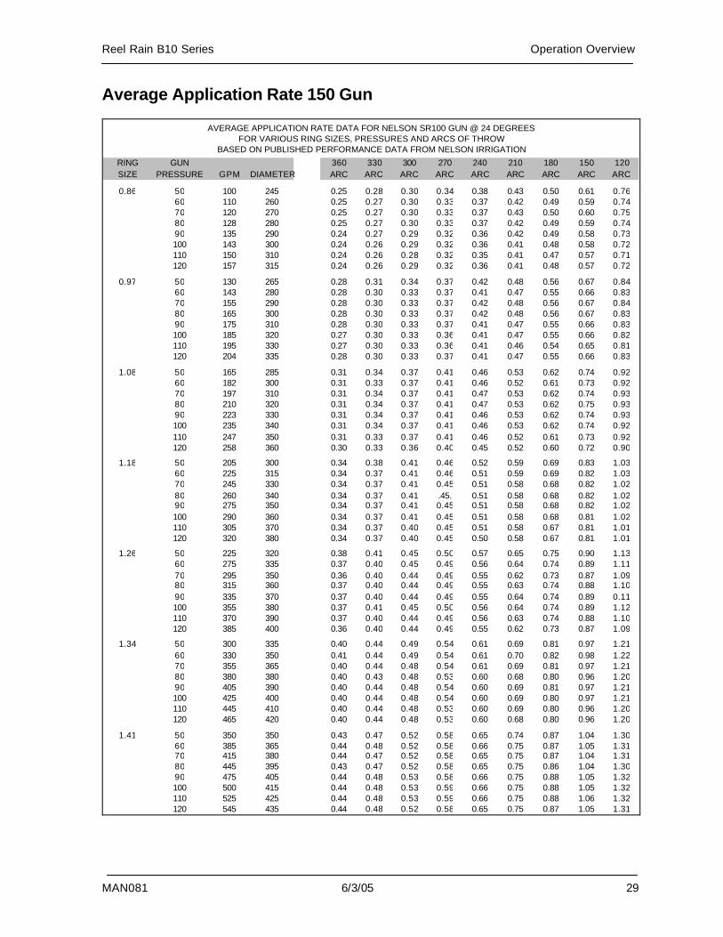
Tiny Tach showing number of hours run Application Rate Flow rates are determined by the water pressure at the gun and the size of the gun nozzle and/or ring. Application rates are determined by a combination of the flow rate and the ground speed of hose retrieval. Gun water pressure + nozzle size = Flow rate Flow rate + hose ground speed = Application rate The charts in this manual and on the machine are provided to help you determine the correct speed, lane spacing, and depth of water to apply for your application. NOTE: If runoff is a problem (typically for wastewater applications), the average application rate should not exceed the initial soil absorption rate. Note that the charts are also posted on the Reel Rain under the gear shifters.
To use the charts: 1. Determine the ring size of your gun. It
should be marked. 2. With the irrigator and water supply
turned on, read the pressure gauges located on the gun and on the inlet elbow of the machine.
3. Referring to the “Gross Application
Depth vs Ground Speed” chart for your model (1025 or 1030), locate your ring size, elbow pressure, gun size, and gun pressure.
Example. For a B1030 with the following: a Nelson 100-24 gun; a ring size .77; an elbow pressure 90 and a gun pressure 81. Locate the .77 ring size on the chart, then locate 90 in the ELBOW PRESS column and 81 in the GUN PRESS column. Note that the GAL PER MINUTE column is 112, and the RECOMMENDED LINE SPACING column is 190 feet.
4. Determine the number of inches you want applied.
Example: You want to apply .5 inches of water.
5. On the same chart, cross reference the
ground speed needed (in feet per minute) to achieve the amount of water you want applied.
Example: Continue across the chart to the APPLICATION DEPTH column for .5” and .77 ring size, 90 elbow pressure and 81 gun pressure. Note that a retrieval ground speed of 1.7 feet per minute is required to lay .5” of water for these specifications.
6. Refer to the “Engine Speed Settings”
chart for your model. Locate the approximate speed you need and set the engine as indicated.
Operation Overview Reel Rain B10 Series
22 6/3/05 MAN081
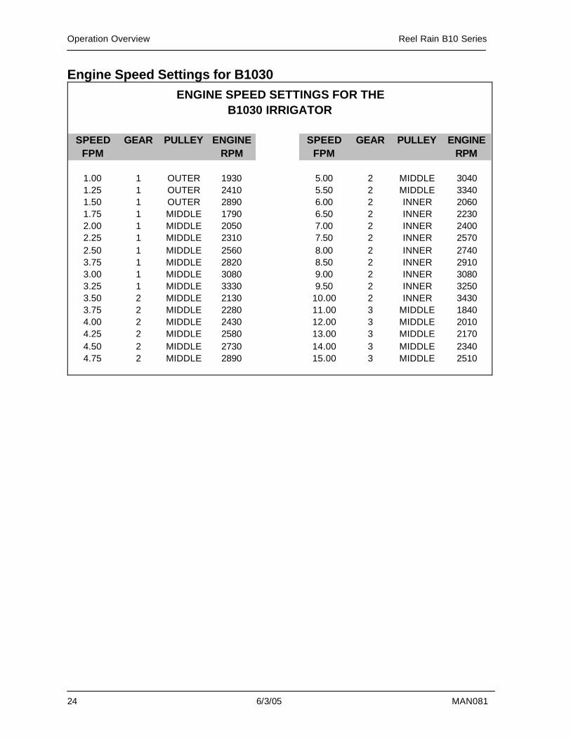
Example: Look at the chart for the Engine Speed Settings for B1030. To achieve the 1.7 feet per minute ground speed, you need to be in first gear, middle pulley, with engine RPM at approximately 1780.
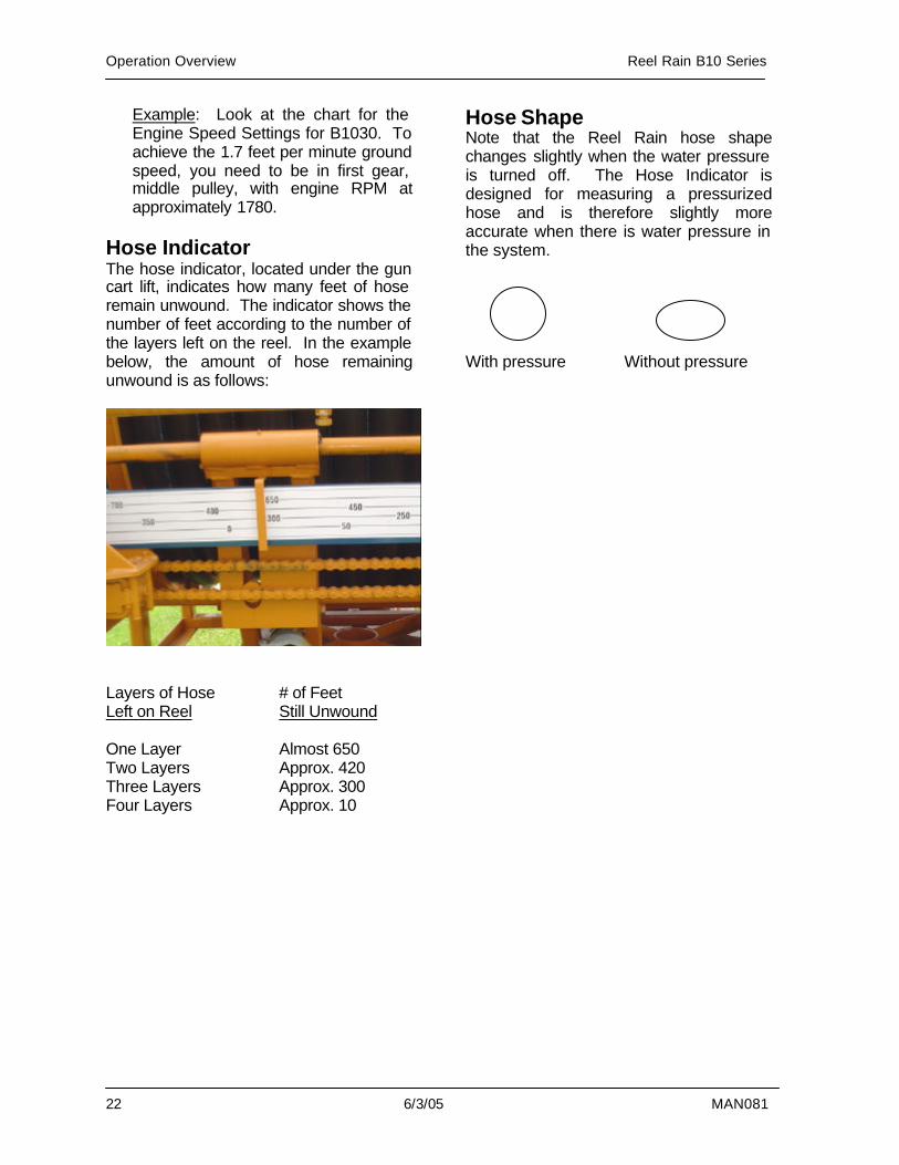
Hose Indicator The hose indicator, located under the gun cart lift, indicates how many feet of hose remain unwound. The indicator shows the number of feet according to the number of the layers left on the reel. In the example below, the amount of hose remaining unwound is as follows:
Layers of Hose Left on Reel One Layer Two Layers Three Layers Four Layers
# of Feet Still Unwound Almost 650 Approx. 420 Approx. 300 Approx. 10
Hose Shape Note that the Reel Rain hose shape changes slightly when the water pressure is turned off. The Hose Indicator is designed for measuring a pressurized hose and is therefore slightly more accurate when there is water pressure in the system. With pressure Without pressure
Reel Rain B10 Series Operation Overview
MAN081 6/3/05 23
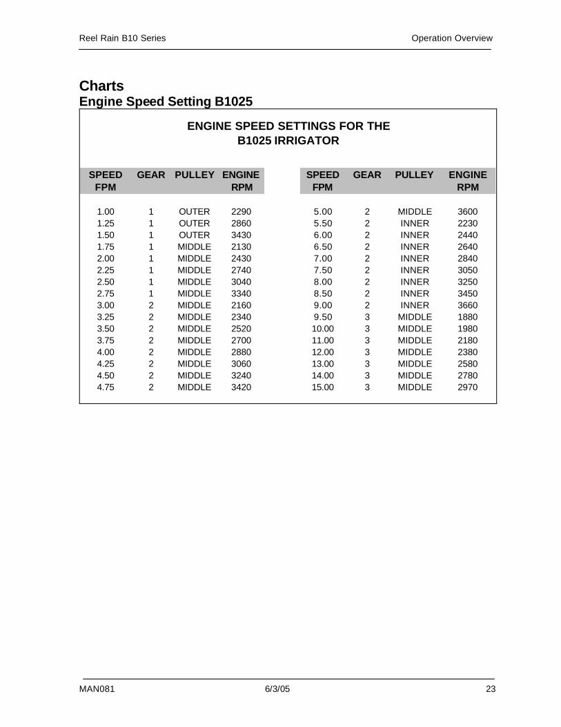
Charts Engine Speed Setting B1025
SPEED FPM
GEAR PULLEY ENGINE RPM
SPEEDFPM
GEAR PULLEY ENGINERPM
1.00 1 OUTER 2290 5.00 2 MIDDLE 36001.25 1 OUTER 2860 5.50 2 INNER 22301.50 1 OUTER 3430 6.00 2 INNER 24401.75 1 MIDDLE 2130 6.50 2 INNER 26402.00 1 MIDDLE 2430 7.00 2 INNER 28402.25 1 MIDDLE 2740 7.50 2 INNER 30502.50 1 MIDDLE 3040 8.00 2 INNER 32502.75 1 MIDDLE 3340 8.50 2 INNER 34503.00 2 MIDDLE 2160 9.00 2 INNER 36603.25 2 MIDDLE 2340 9.50 3 MIDDLE 18803.50 2 MIDDLE 2520 10.00 3 MIDDLE 19803.75 2 MIDDLE 2700 11.00 3 MIDDLE 21804.00 2 MIDDLE 2880 12.00 3 MIDDLE 23804.25 2 MIDDLE 3060 13.00 3 MIDDLE 25804.50 2 MIDDLE 3240 14.00 3 MIDDLE 27804.75 2 MIDDLE 3420 15.00 3 MIDDLE 2970
ENGINE SPEED SETTINGS FOR THEB1025 IRRIGATOR
Operation Overview Reel Rain B10 Series
24 6/3/05 MAN081
Engine Speed Settings for B1030
SPEEDFPM
GEAR PULLEY ENGINERPM
SPEEDFPM
GEAR PULLEY ENGINERPM
1.00 1 OUTER 1930 5.00 2 MIDDLE 30401.25 1 OUTER 2410 5.50 2 MIDDLE 33401.50 1 OUTER 2890 6.00 2 INNER 20601.75 1 MIDDLE 1790 6.50 2 INNER 22302.00 1 MIDDLE 2050 7.00 2 INNER 24002.25 1 MIDDLE 2310 7.50 2 INNER 25702.50 1 MIDDLE 2560 8.00 2 INNER 27403.75 1 MIDDLE 2820 8.50 2 INNER 29103.00 1 MIDDLE 3080 9.00 2 INNER 30803.25 1 MIDDLE 3330 9.50 2 INNER 32503.50 2 MIDDLE 2130 10.00 2 INNER 34303.75 2 MIDDLE 2280 11.00 3 MIDDLE 18404.00 2 MIDDLE 2430 12.00 3 MIDDLE 20104.25 2 MIDDLE 2580 13.00 3 MIDDLE 21704.50 2 MIDDLE 2730 14.00 3 MIDDLE 23404.75 2 MIDDLE 2890 15.00 3 MIDDLE 2510
ENGINE SPEED SETTINGS FOR THEB1030 IRRIGATOR
Reel Rain B10 Series Operation Overview
MAN081 6/3/05 25
Gross Application B1025
GROSS APPLICATION DEPTH VS. GROUND SPEEDMODEL B1025G4 W/ NELSON SR100-24 GUN & RING NOZZLES
RING ELBOW GUN GALLONS PER RECOMMENDED APPLICATION DEPTH (IN INCHES) VS. GROUND SPEED (IN FEET PER MINUTE) DIAMETERSIZE PRESSURE PRESSURE MINUTE LANE SPACING 0.1 0.2 0.25 0.3 0.4 0.5 0.6 0.7 0.75 0.8 0.9 1.00.71 80 62 83 170 7.3 3.6 2.9 2.4 1.8 1.5 1.2 1.0 1.0 0.9 0.8 0.7 238
90 70 88 170 7.7 3.8 3.1 2.6 1.9 1.5 1.3 1.1 1.0 1.0 0.9 0.8 245100 78 93 180 7.6 3.8 3.1 2.5 1.9 1.5 1.3 1.1 1.0 1.0 0.8 0.8 253110 86 98 180 8.0 4.0 3.2 2.7 2.0 1.6 1.3 1.1 1.1 1.0 0.9 0.8 262120 94 102 190 7.9 4.0 3.2 2.6 2.0 1.6 1.3 1.1 1.1 1.0 0.9 0.8 267.5
0.77 80 58 94 170 8.3 4.1 3.3 2.8 2.1 1.7 1.4 1.2 1.1 1.0 0.9 0.8 23790 65 100 170 8.7 4.4 3.5 2.9 2.2 1.7 1.5 1.2 1.2 1.1 1.0 0.9 245
100 73 105 180 8.7 4.3 3.5 2.9 2.2 1.7 1.4 1.2 1.2 1.1 1.0 0.9 253110 80 111 190 8.6 4.3 3.4 2.9 2.2 1.7 1.4 1.2 1.1 1.1 1.0 0.9 265120 88 116 190 9.0 4.5 3.6 3.0 2.2 1.8 1.5 1.3 1.2 1.1 1.0 0.9 273130 95 121 190 9.4 4.7 3.7 3.1 2.3 1.9 1.6 1.3 1.2 1.2 1.0 0.9 277.5
0.81 90 60 110 170 9.6 4.8 3.8 3.2 2.4 1.9 1.6 1.4 1.3 1.2 1.1 1.0 245100 67 116 180 9.6 4.8 3.8 3.2 2.4 1.9 1.6 1.4 1.3 1.2 1.1 1.0 257110 74 122 190 9.4 4.7 3.8 3.1 2.4 1.9 1.6 1.3 1.3 1.2 1.0 0.9 266120 81 128 190 9.9 5.0 4.0 3.3 2.5 2.0 1.7 1.4 1.3 1.2 1.1 1.0 276130 88 133 200 9.7 4.9 3.9 3.2 2.4 1.9 1.6 1.4 1.3 1.2 1.1 1.0 283140 95 138 200 10.1 5.1 4.1 3.4 2.5 2.0 1.7 1.4 1.4 1.3 1.1 1.0 290
0.86 100 62 126 180 10.4 5.2 4.1 3.5 2.6 2.1 1.7 1.5 1.4 1.3 1.2 1.0 261.5110 68 133 190 10.3 5.2 4.1 3.4 2.6 2.1 1.7 1.5 1.4 1.3 1.1 1.0 272120 74 139 200 10.2 5.1 4.1 3.4 2.6 2.0 1.7 1.5 1.4 1.3 1.1 1.0 279130 81 145 200 10.6 5.3 4.3 3.5 2.7 2.1 1.8 1.5 1.4 1.3 1.2 1.1 285140 87 151 200 11.1 5.6 4.4 3.7 2.8 2.2 1.9 1.6 1.5 1.4 1.2 1.1 292150 93 156 210 10.9 5.4 4.4 3.6 2.7 2.2 1.8 1.6 1.5 1.4 1.2 1.1 298
0.89 100 56 136 180 11.2 5.6 4.5 3.7 2.8 2.2 1.9 1.6 1.5 1.4 1.2 1.1 262110 62 143 190 11.1 5.6 4.4 3.7 2.8 2.2 1.9 1.6 1.5 1.4 1.2 1.1 274120 68 150 200 11.0 5.5 4.4 3.7 2.7 2.2 1.8 1.6 1.5 1.4 1.2 1.1 286130 74 155 210 10.8 5.4 4.3 3.6 2.7 2.2 1.8 1.5 1.4 1.4 1.2 1.1 293140 80 162 210 11.3 5.6 4.5 3.8 2.8 2.3 1.9 1.6 1.5 1.4 1.3 1.1 299150 85 168 210 11.7 5.8 4.7 3.9 2.9 2.3 1.9 1.7 1.6 1.5 1.3 1.2 305
0.93 120 59 163 190 12.6 6.3 5.0 4.2 3.2 2.5 2.1 1.8 1.7 1.6 1.4 1.3 273130 64 169 200 12.4 6.2 5.0 4.1 3.1 2.5 2.1 1.8 1.7 1.6 1.4 1.2 283140 70 176 210 12.2 6.1 4.9 4.1 3.1 2.4 2.0 1.7 1.6 1.5 1.4 1.2 293150 75 182 210 12.7 6.3 5.1 4.2 3.2 2.5 2.1 1.8 1.7 1.6 1.4 1.3 299
0.96 120 53 172 190 13.3 6.7 5.3 4.4 3.3 2.7 2.2 1.9 1.8 1.7 1.5 1.3 266130 57 180 190 14.0 7.0 5.6 4.7 3.5 2.8 2.3 2.0 1.9 1.7 1.6 1.4 276140 62 186 200 13.6 6.8 5.5 4.5 3.4 2.7 2.3 1.9 1.8 1.7 1.5 1.4 284150 67 192 210 13.4 6.7 5.4 4.5 3.3 2.7 2.2 1.9 1.8 1.7 1.5 1.3 294

Operation Overview Reel Rain B10 Series
26 6/3/05 MAN081
Gross Application B1030
GROSS APPLICATION DEPTH VS. GROUND SPEEDMODEL B1030G4 W/ NELSON SR100-24 GUN & RING NOZZLES
RING ELBOW GUN GALLONS PER RECOMMENDED APPLICATION DEPTH (IN INCHES) VS. GROUND SPEED (IN FEET PER MINUTE) DIAMETERSIZE PRESSURE PRESSURE MINUTE LANE SPACING 0.1 0.2 0.25 0.3 0.4 0.5 0.6 0.7 0.75 0.8 0.9 1.00.71 60 55 78 160 7.1 3.6 2.9 2.4 1.8 1.4 1.2 1.0 1.0 0.9 0.8 0.7 227.5
70 64 84 170 7.2 3.6 2.9 2.4 1.8 1.4 1.2 1.0 1.0 0.9 0.8 0.7 23980 74 90 170 7.8 3.9 3.1 2.6 1.9 1.6 1.3 1.1 1.0 1.0 0.9 0.8 24990 83 96 180 7.7 3.9 3.1 2.6 1.9 1.5 1.3 1.1 1.0 1.0 0.9 0.8 258
100 92 100 190 7.6 3.8 3.1 2.5 1.9 1.5 1.3 1.1 1.0 1.0 0.8 0.8 266110 101 106 190 8.1 4.0 3.2 2.7 2.0 1.6 1.3 1.2 1.1 1.0 0.9 0.8 271
0.77 60 54 91 160 8.4 4.2 3.4 2.8 2.1 1.7 1.4 1.2 1.1 1.0 0.9 0.8 23170 63 98 170 8.5 4.2 3.4 2.8 2.1 1.7 1.4 1.2 1.1 1.1 0.9 0.8 24380 72 105 180 8.5 4.3 3.4 2.8 2.1 1.7 1.4 1.2 1.1 1.1 0.9 0.9 25390 81 112 190 8.5 4.3 3.4 2.8 2.1 1.7 1.4 1.2 1.1 1.1 0.9 0.9 266
100 90 117 190 8.9 4.5 3.6 3.0 2.2 1.8 1.5 1.3 1.2 1.1 1.0 0.9 275110 99 123 200 8.9 4.4 3.6 3.0 2.2 1.8 1.5 1.3 1.2 1.1 1.0 0.9 279.5
0.81 60 52 102 160 9.4 4.7 3.8 3.1 2.3 1.9 1.6 1.3 1.3 1.2 1.0 0.9 23370 61 111 170 9.5 4.8 3.8 3.2 2.4 1.9 1.6 1.4 1.3 1.2 1.1 1.0 246.580 70 118 180 9.6 4.8 3.8 3.2 2.4 1.9 1.6 1.4 1.3 1.2 1.1 1.0 26090 78 125 190 9.6 4.8 3.8 3.2 2.4 1.9 1.6 1.4 1.3 1.2 1.1 1.0 272
100 87 132 200 9.5 4.8 3.8 3.2 2.4 1.9 1.6 1.4 1.3 1.2 1.1 1.0 282110 96 139 200 10.0 5.0 4.0 3.3 2.5 2.0 1.7 1.4 1.3 1.3 1.1 1.0 291
0.86 60 50 115 170 9.9 5.0 4.0 3.3 2.5 2.0 1.7 1.4 1.3 1.2 1.1 1.0 24070 59 124 180 10.0 5.0 4.0 3.3 2.5 2.0 1.7 1.4 1.3 1.3 1.1 1.0 25880 67 132 190 10.1 5.0 4.0 3.4 2.5 2.0 1.7 1.4 1.3 1.3 1.1 1.0 270.590 76 141 200 10.2 5.1 4.1 3.4 2.5 2.0 1.7 1.5 1.4 1.3 1.1 1.0 281
100 84 149 200 10.7 5.4 4.3 3.6 2.7 2.1 1.8 1.5 1.4 1.3 1.2 1.1 289110 92 156 210 10.7 5.3 4.3 3.6 2.7 2.1 1.8 1.5 1.4 1.3 1.2 1.1 298
0.89 70 56 136 180 11.0 5.5 4.4 3.7 2.8 2.2 1.8 1.6 1.5 1.4 1.2 1.1 26280 64 147 200 10.6 5.3 4.2 3.5 2.6 2.1 1.8 1.5 1.4 1.3 1.2 1.1 28090 73 155 210 10.6 5.3 4.2 3.5 2.7 2.1 1.8 1.5 1.4 1.3 1.2 1.1 293
100 81 164 210 11.2 5.6 4.5 3.7 2.8 2.2 1.9 1.6 1.5 1.4 1.2 1.1 301110 89 172 220 11.2 5.6 4.5 3.7 2.8 2.2 1.9 1.6 1.5 1.4 1.2 1.1 309120 97 179 220 11.6 5.8 4.7 3.9 2.9 2.3 1.9 1.7 1.6 1.5 1.3 1.2 317
0.93 70 53 154 180 12.5 6.2 5.0 4.2 3.1 2.5 2.1 1.8 1.7 1.6 1.4 1.2 26180 61 165 190 12.6 6.3 5.0 4.2 3.2 2.5 2.1 1.8 1.7 1.6 1.4 1.3 277
100 76 184 210 12.6 6.3 5.0 4.2 3.1 2.5 2.1 1.8 1.7 1.6 1.4 1.3 301110 84 194 220 12.6 6.3 5.0 4.2 3.1 2.5 2.1 1.8 1.7 1.6 1.4 1.3 309120 92 203 220 13.2 6.6 5.3 4.4 3.3 2.6 2.2 1.9 1.8 1.6 1.5 1.3 317130 99 212 230 13.1 6.5 5.2 4.4 3.3 2.6 2.2 1.9 1.7 1.6 1.5 1.3 325
0.96 70 50 167 180 13.5 6.8 5.4 4.5 3.4 2.7 2.3 1.9 1.8 1.7 1.5 1.4 26080 57 180 190 13.7 6.9 5.5 4.6 3.4 2.7 2.3 2.0 1.8 1.7 1.5 1.4 27690 65 190 200 13.7 6.8 5.5 4.6 3.4 2.7 2.3 2.0 1.8 1.7 1.5 1.4 29090 65 191 200 13.8 6.9 5.5 4.6 3.4 2.8 2.3 2.0 1.8 1.7 1.5 1.4 292
100 72 201 210 13.7 6.9 5.5 4.6 3.4 2.7 2.3 2.0 1.8 1.7 1.5 1.4 304.5110 79 211 220 13.7 6.8 5.5 4.6 3.4 2.7 2.3 2.0 1.8 1.7 1.5 1.4 315120 87 220 230 13.6 6.8 5.4 4.5 3.4 2.7 2.3 1.9 1.8 1.7 1.5 1.4 322130 94 230 230 14.2 7.1 5.7 4.7 3.6 2.8 2.4 2.0 1.9 1.8 1.6 1.4 330
Reel Rain B10 Series Operation Overview
MAN081 6/3/05 27
Gross Application Rate 1030 150 Gun
GROSS APPLICATION DEPTH VS. GROUND SPEEDMODEL B1030 W/ NELSON SR150-24 GUN & RING NOZZLES
RING ELBOW GUN GALLONS PER RECOMMENDED APPLICATION DEPTH (IN INCHES) VS. GROUND SPEED (IN FEET PER MINUTE) DIAMETERSIZE PRESSURE PRESSURE MINUTE LANE SPACING 0.1 0.2 0.25 0.3 0.4 0.5 0.6 0.7 0.75 0.8 0.9 1.00.86 60 52 102 170 8.8 4.4 3.5 2.9 2.2 1.8 1.5 1.3 1.2 1.1 1.0 0.9 248
70 61 111 180 9.0 4.5 3.6 3.0 2.2 1.8 1.5 1.3 1.2 1.1 1.0 0.9 26180 69 119 190 9.1 4.5 3.6 3.0 2.3 1.8 1.5 1.3 1.2 1.1 1.0 0.9 26990 78 126 190 9.6 4.8 3.9 3.2 2.4 1.9 1.6 1.4 1.3 1.2 1.1 1.0 278
100 87 133 200 9.6 4.8 3.8 3.2 2.4 1.9 1.6 1.4 1.3 1.2 1.1 1.0 287110 96 140 210 9.6 4.8 3.8 3.2 2.4 1.9 1.6 1.4 1.3 1.2 1.1 1.0 296
0.97 70 57 135 190 10.3 5.1 4.1 3.4 2.6 2.1 1.7 1.5 1.4 1.3 1.1 1.0 275.580 64 148 200 10.7 5.3 4.3 3.6 2.7 2.1 1.8 1.5 1.4 1.3 1.2 1.1 28490 72 157 200 11.3 5.7 4.5 3.8 2.8 2.3 1.9 1.6 1.5 1.4 1.3 1.1 292
100 80 166 210 11.3 5.7 4.5 3.8 2.8 2.3 1.9 1.6 1.5 1.4 1.3 1.1 301110 89 174 220 11.3 5.6 4.5 3.8 2.8 2.3 1.9 1.6 1.5 1.4 1.3 1.1 309120 97 182 220 11.8 5.9 4.7 3.9 3.0 2.4 2.0 1.7 1.6 1.5 1.3 1.2 317
1.08 70 50 167 200 12.0 6.0 4.8 4.0 3.0 2.4 2.0 1.7 1.6 1.5 1.3 1.2 286.580 58 179 210 12.2 6.1 4.9 4.1 3.1 2.4 2.0 1.7 1.6 1.5 1.4 1.2 29790 65 190 210 13.0 6.5 5.2 4.3 3.2 2.6 2.2 1.9 1.7 1.6 1.4 1.3 305
100 72 200 220 13.0 6.5 5.2 4.3 3.2 2.6 2.2 1.9 1.7 1.6 1.4 1.3 312110 80 210 220 13.6 6.8 5.5 4.5 3.4 2.7 2.3 1.9 1.8 1.7 1.5 1.4 320120 87 219 230 13.5 6.8 5.4 4.5 3.4 2.7 2.3 1.9 1.8 1.7 1.5 1.4 327130 94 229 230 14.1 7.1 5.7 4.7 3.5 2.8 2.4 2.0 1.9 1.8 1.6 1.4 335
1.18 80 51 207 210 14.1 7.1 5.7 4.7 3.5 2.8 2.4 2.0 1.9 1.8 1.6 1.4 301.590 57 219 220 14.2 7.1 5.7 4.7 3.6 2.8 2.4 2.0 1.9 1.8 1.6 1.4 310.5
100 63 233 220 7.6 6.0 5.0 3.8 3.0 2.5 2.2 2.0 1.9 1.7 1.5 321110 70 245 230 7.6 6.1 5.0 3.8 3.0 2.5 2.2 2.0 1.9 1.7 1.5 330120 77 256 240 7.5 6.0 5.0 3.8 3.0 2.5 2.2 2.0 1.9 1.7 1.5 337130 83 266 240 7.8 6.3 5.2 3.9 3.1 2.6 2.2 2.1 2.0 1.7 1.6 344140 90 275 250 7.7 6.2 5.2 3.9 3.1 2.6 2.2 2.1 1.9 1.7 1.5 350150 97 286 250 8.0 6.4 5.4 4.0 3.2 2.7 2.3 2.1 2.0 1.8 1.6 357
1.26 100 54 263 230 8.1 6.5 5.4 4.1 3.2 2.7 2.3 2.2 2.0 1.8 1.6 326110 60 275 230 8.5 6.8 5.7 4.2 3.4 2.8 2.4 2.3 2.1 1.9 1.7 335120 66 287 240 8.5 6.8 5.6 4.2 3.4 2.8 2.4 2.3 2.1 1.9 1.7 344130 72 299 250 8.4 6.7 5.6 4.2 3.4 2.8 2.4 2.2 2.1 1.9 1.7 352140 77 311 250 8.8 7.0 5.8 4.4 3.5 2.9 2.5 2.3 2.2 1.9 1.8 358150 83 323 250 9.1 7.3 6.1 4.5 3.6 3.0 2.6 2.4 2.3 2.0 1.8 364
1.34 110 50 303 240 8.9 7.1 6.0 4.5 3.6 3.0 2.6 2.4 2.2 2.0 1.8 336.5120 55 318 240 9.4 7.5 6.2 4.7 3.7 3.1 2.7 2.5 2.3 2.1 1.9 344130 60 330 250 9.3 7.4 6.2 4.6 3.7 3.1 2.7 2.5 2.3 2.1 1.9 350140 65 343 250 9.6 7.7 6.4 4.8 3.9 3.2 2.8 2.6 2.4 2.1 1.9 357.5150 70 355 260 9.6 7.6 6.4 4.8 3.8 3.2 2.7 2.5 2.4 2.1 1.9 365
1.41 130 51 354 250 9.9 8.0 6.6 5.0 4.0 3.3 2.8 2.7 2.5 2.2 2.0 351.5140 55 368 250 10.3 8.3 6.9 5.2 4.1 3.4 3.0 2.8 2.6 2.3 2.1 357.5150 59 382 250 10.7 8.6 7.2 5.4 4.3 3.6 3.1 2.9 2.7 2.4 2.1 363.5
Operation Overview Reel Rain B10 Series
28 6/3/05 MAN081
Average Application Rate 100 Gun
RINGSIZE
GUNPRESSURE GPM DIAMETER
360ARC
330ARC
300ARC
270ARC
240ARC
210ARC
180ARC
150ARC
120ARC
0.71 50 74 220 0.23 0.25 0.28 0.31 0.35 0.40 0.46 0.56 0.6960 81 235 0.22 0.24 0.27 0.30 0.33 0.38 0.44 0.53 0.6770 88 245 0.22 0.24 0.27 0.30 0.33 0.38 0.44 0.53 0.6780 94 255 0.22 0.24 0.26 0.29 0.33 0.38 0.44 0.53 0.6690 99 265 0.21 0.23 0.26 0.28 0.32 0.37 0.43 0.51 0.64100 105 270 0.22 0.24 0.26 0.29 0.33 0.37 0.44 0.52 0.65110 110 275 0.22 0.24 0.26 0.29 0.33 0.38 0.44 0.53 0.66
0.77 50 88 225 0.26 0.29 0.32 0.35 0.39 0.45 0.53 0.63 0.7960 96 240 0.25 0.28 0.30 0.34 0.38 0.43 0.50 0.61 0.7670 104 250 0.25 0.27 0.30 0.34 0.38 0.43 0.50 0.60 0.7680 111 265 0.24 0.26 0.29 0.32 0.36 0.41 0.48 0.51 0.7290 117 275 0.23 0.26 0.28 0.31 0.35 0.40 0.47 0.56 0.70100 124 280 0.24 0.26 0.29 0.32 0.36 0.41 0.48 0.57 0.72110 130 290 0.23 0.26 0.28 0.31 0.35 0.40 0.47 0.56 0.70
0.81 50 100 230 0.29 0.31 0.34 0.38 0.43 0.49 0.57 0.69 0.8660 110 245 0.28 0.30 0.33 0.37 0.42 0.48 0.55 0.67 0.8370 118 260 0.26 0.29 0.32 0.35 0.40 0.45 0.53 0.63 0.7980 127 275 0.25 0.28 0.31 0.34 0.38 0.44 0.51 0.61 0.7690 134 285 0.25 0.27 0.30 0.33 0.37 0.43 0.50 0.60 0.75100 142 295 0.25 0.27 0.30 0.33 0.37 0.42 0.49 0.59 0.74110 149 305 0.24 0.26 0.29 0.32 0.36 0.42 0.48 0.58 0.73
0.86 50 115 240 0.30 0.33 0.36 0.40 0.45 0.52 0.60 0.73 0.9160 125 260 0.28 0.31 0.34 0.37 0.42 0.48 0.56 0.67 0.8470 135 275 0.27 0.29 0.32 0.36 0.41 0.46 0.54 0.65 0.8180 145 285 0.27 0.29 0.32 0.36 0.41 0.46 0.54 0.65 0.8190 154 295 0.27 0.29 0.32 0.36 0.40 0.46 0.54 0.64 0.80100 162 305 0.26 0.29 0.32 0.35 0.40 0.45 0.53 0.63 0.79110 170 315 0.26 0.28 0.31 0.35 0.39 0.44 0.52 0.62 0.78
0.89 50 129 250 0.31 0.34 0.37 0.42 0.47 0.54 0.62 0.75 0.9460 141 270 0.29 0.32 0.35 0.39 0.44 0.50 0.59 0.70 0.8870 152 290 0.27 0.30 0.33 0.36 0.41 0.47 0.55 0.66 0.8280 163 300 0.27 0.30 0.33 0.37 0.41 0.47 0.55 0.66 0.8290 173 310 0.27 0.30 0.33 0.36 0.41 0.47 0.55 0.65 0.82100 182 320 0.27 0.29 0.32 0.36 0.40 0.46 0.54 0.65 0.81110 191 325 0.27 0.30 0.33 0.36 0.41 0.47 0.55 0.66 0.82
0.93 50 150 255 0.35 0.38 0.34 0.47 0.52 0.60 0.70 0.84 1.0560 164 275 0.33 0.36 0.39 0.44 0.49 0.56 0.66 0.79 0.9870 177 295 0.31 0.34 0.37 0.41 0.46 0.53 0.62 0.74 0.9280 189 305 0.31 0.34 0.37 0.41 0.46 0.53 0.62 0.74 0.9290 201 315 0.31 0.33 0.37 0.41 0.46 0.53 0.61 0.74 0.92100 212 325 0.30 0.33 0.36 0.41 0.46 0.52 0.61 0.73 0.91110 222 325 0.30 0.33 0.36 0.40 0.45 0.51 0.60 0.72 0.90
0.96 50 167 260 0.37 0.41 0.45 0.50 0.56 0.64 0.75 0.90 1.1260 183 280 0.35 0.39 0.42 0.47 0.53 0.61 0.71 0.85 1.0670 198 300 0.33 0.36 0.40 0.44 0.50 0.57 0.67 0.80 1.0080 211 315 0.32 0.35 0.39 0.43 0.48 0.55 0.64 0.77 0.9790 224 325 0.32 0.35 0.39 0.43 0.48 0.55 0.64 0.77 0.96100 236 335 0.32 0.35 0.38 0.42 0.48 0.55 0.64 0.76 0.96110 248 345 0.32 0.34 0.38 0.42 0.47 0.54 0.63 0.76 0.95
AVERAGE APPLICATION RATE DATA FOR NELSON SR100 GUN @ 24 DEGREESFOR VARIOUS RING SIZES, PRESSURES AND ARCS OF THROW
BASED ON PUBLISHED PERFORMANCE DATA FROM NELSON IRRIGATION
Reel Rain B10 Series Operation Overview
MAN081 6/3/05 29
Average Application Rate 150 Gun
RINGSIZE
GUNPRESSURE GPM DIAMETER
360ARC
330ARC
300ARC
270ARC
240ARC
210ARC
180ARC
150ARC
120ARC
0.86 50 100 245 0.25 0.28 0.30 0.34 0.38 0.43 0.50 0.61 0.7660 110 260 0.25 0.27 0.30 0.33 0.37 0.42 0.49 0.59 0.7470 120 270 0.25 0.27 0.30 0.33 0.37 0.43 0.50 0.60 0.7580 128 280 0.25 0.27 0.30 0.33 0.37 0.42 0.49 0.59 0.7490 135 290 0.24 0.27 0.29 0.32 0.36 0.42 0.49 0.58 0.73100 143 300 0.24 0.26 0.29 0.32 0.36 0.41 0.48 0.58 0.72110 150 310 0.24 0.26 0.28 0.32 0.35 0.41 0.47 0.57 0.71120 157 315 0.24 0.26 0.29 0.32 0.36 0.41 0.48 0.57 0.72
0.97 50 130 265 0.28 0.31 0.34 0.37 0.42 0.48 0.56 0.67 0.8460 143 280 0.28 0.30 0.33 0.37 0.41 0.47 0.55 0.66 0.8370 155 290 0.28 0.30 0.33 0.37 0.42 0.48 0.56 0.67 0.8480 165 300 0.28 0.30 0.33 0.37 0.42 0.48 0.56 0.67 0.8390 175 310 0.28 0.30 0.33 0.37 0.41 0.47 0.55 0.66 0.83100 185 320 0.27 0.30 0.33 0.36 0.41 0.47 0.55 0.66 0.82110 195 330 0.27 0.30 0.33 0.36 0.41 0.46 0.54 0.65 0.81120 204 335 0.28 0.30 0.33 0.37 0.41 0.47 0.55 0.66 0.83
1.08 50 165 285 0.31 0.34 0.37 0.41 0.46 0.53 0.62 0.74 0.9260 182 300 0.31 0.33 0.37 0.41 0.46 0.52 0.61 0.73 0.9270 197 310 0.31 0.34 0.37 0.41 0.47 0.53 0.62 0.74 0.9380 210 320 0.31 0.34 0.37 0.41 0.47 0.53 0.62 0.75 0.9390 223 330 0.31 0.34 0.37 0.41 0.46 0.53 0.62 0.74 0.93100 235 340 0.31 0.34 0.37 0.41 0.46 0.53 0.62 0.74 0.92110 247 350 0.31 0.33 0.37 0.41 0.46 0.52 0.61 0.73 0.92120 258 360 0.30 0.33 0.36 0.40 0.45 0.52 0.60 0.72 0.90
1.18 50 205 300 0.34 0.38 0.41 0.46 0.52 0.59 0.69 0.83 1.0360 225 315 0.34 0.37 0.41 0.46 0.51 0.59 0.69 0.82 1.0370 245 330 0.34 0.37 0.41 0.45 0.51 0.58 0.68 0.82 1.0280 260 340 0.34 0.37 0.41 .45. 0.51 0.58 0.68 0.82 1.0290 275 350 0.34 0.37 0.41 0.45 0.51 0.58 0.68 0.82 1.02100 290 360 0.34 0.37 0.41 0.45 0.51 0.58 0.68 0.81 1.02110 305 370 0.34 0.37 0.40 0.45 0.51 0.58 0.67 0.81 1.01120 320 380 0.34 0.37 0.40 0.45 0.50 0.58 0.67 0.81 1.01
1.26 50 225 320 0.38 0.41 0.45 0.50 0.57 0.65 0.75 0.90 1.1360 275 335 0.37 0.40 0.45 0.49 0.56 0.64 0.74 0.89 1.1170 295 350 0.36 0.40 0.44 0.49 0.55 0.62 0.73 0.87 1.0980 315 360 0.37 0.40 0.44 0.49 0.55 0.63 0.74 0.88 1.1090 335 370 0.37 0.40 0.44 0.49 0.55 0.64 0.74 0.89 0.11100 355 380 0.37 0.41 0.45 0.50 0.56 0.64 0.74 0.89 1.12110 370 390 0.37 0.40 0.44 0.49 0.56 0.63 0.74 0.88 1.10120 385 400 0.36 0.40 0.44 0.49 0.55 0.62 0.73 0.87 1.09
1.34 50 300 335 0.40 0.44 0.49 0.54 0.61 0.69 0.81 0.97 1.2160 330 350 0.41 0.44 0.49 0.54 0.61 0.70 0.82 0.98 1.2270 355 365 0.40 0.44 0.48 0.54 0.61 0.69 0.81 0.97 1.2180 380 380 0.40 0.43 0.48 0.53 0.60 0.68 0.80 0.96 1.2090 405 390 0.40 0.44 0.48 0.54 0.60 0.69 0.81 0.97 1.21100 425 400 0.40 0.44 0.48 0.54 0.60 0.69 0.80 0.97 1.21110 445 410 0.40 0.44 0.48 0.53 0.60 0.69 0.80 0.96 1.20120 465 420 0.40 0.44 0.48 0.53 0.60 0.68 0.80 0.96 1.20
1.41 50 350 350 0.43 0.47 0.52 0.58 0.65 0.74 0.87 1.04 1.3060 385 365 0.44 0.48 0.52 0.58 0.66 0.75 0.87 1.05 1.3170 415 380 0.44 0.47 0.52 0.58 0.65 0.75 0.87 1.04 1.3180 445 395 0.43 0.47 0.52 0.58 0.65 0.75 0.86 1.04 1.3090 475 405 0.44 0.48 0.53 0.58 0.66 0.75 0.88 1.05 1.32100 500 415 0.44 0.48 0.53 0.59 0.66 0.75 0.88 1.05 1.32110 525 425 0.44 0.48 0.53 0.59 0.66 0.75 0.88 1.06 1.32120 545 435 0.44 0.48 0.52 0.58 0.65 0.75 0.87 1.05 1.31
AVERAGE APPLICATION RATE DATA FOR NELSON SR100 GUN @ 24 DEGREESFOR VARIOUS RING SIZES, PRESSURES AND ARCS OF THROW
BASED ON PUBLISHED PERFORMANCE DATA FROM NELSON IRRIGATION

Operation Overview Reel Rain B10 Series
30 6/3/05 MAN081
NOTES:
Reel Rain B10 Series Machine Setup
MAN081 6/3/05 31
4. Machine Setup
Towing .....................................................32 Checklist ..............................................32 Tow to Field .........................................33
Machine Setup.........................................35 Position Machine .................................35 Ready Machine....................................36 Set Up Gun Cart ..................................37 Connect Hose......................................38 Pull Out Hose.......................................39 Connect to Water Supply.....................40 Make Adjustments ...............................40
Machine Set up Reel Rain B10 Series
32 6/3/05 MAN081
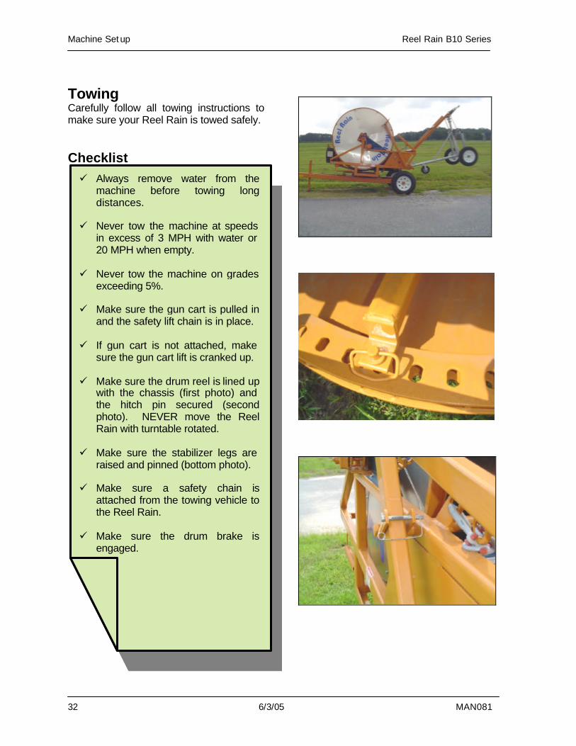
Towing Carefully follow all towing instructions to make sure your Reel Rain is towed safely. Checklist
ü Always remove water from the machine before towing long distances.
ü Never tow the machine at speeds
in excess of 3 MPH with water or 20 MPH when empty.
ü Never tow the machine on grades
exceeding 5%. ü Make sure the gun cart is pulled in
and the safety lift chain is in place. ü If gun cart is not attached, make
sure the gun cart lift is cranked up. ü Make sure the drum reel is lined up
with the chassis (first photo) and the hitch pin secured (second photo). NEVER move the Reel Rain with turntable rotated.
ü Make sure the stabilizer legs are
raised and pinned (bottom photo). ü Make sure a safety chain is
attached from the towing vehicle to the Reel Rain.
ü Make sure the drum brake is
engaged.
Reel Rain B10 Series Machine Setup
MAN081 6/3/05 33
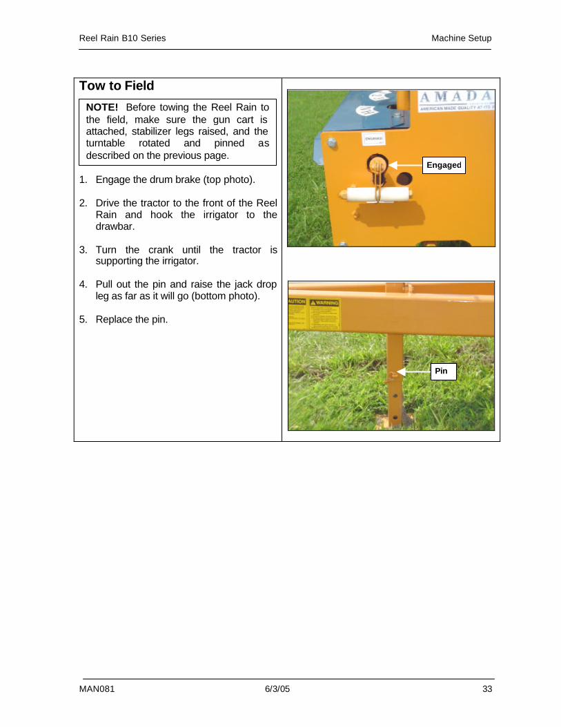
Tow to Field 1. Engage the drum brake (top photo). 2. Drive the tractor to the front of the Reel
Rain and hook the irrigator to the drawbar.
3. Turn the crank until the tractor is
supporting the irrigator. 4. Pull out the pin and raise the jack drop
leg as far as it will go (bottom photo). 5. Replace the pin.
NOTE! Before towing the Reel Rain to the field, make sure the gun cart is attached, stabilizer legs raised, and the turntable rotated and pinned as described on the previous page.
Engaged
Pin
Machine Set up Reel Rain B10 Series
34 6/3/05 MAN081
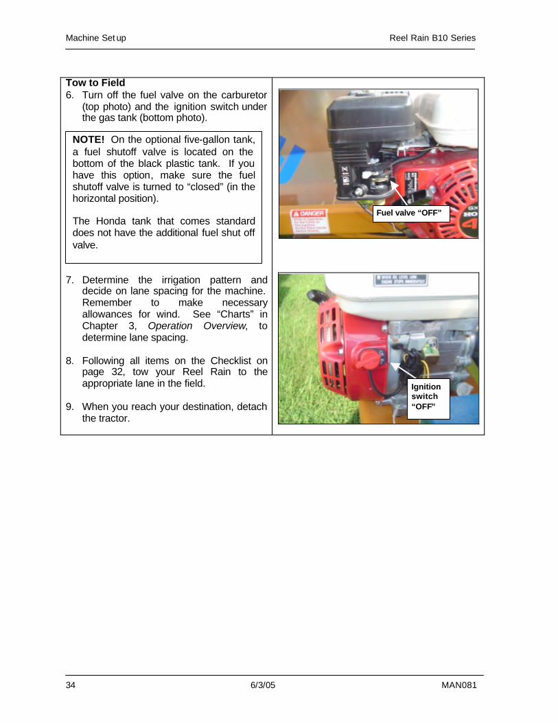
Tow to Field 6. Turn off the fuel valve on the carburetor
(top photo) and the ignition switch under the gas tank (bottom photo).
7. Determine the irrigation pattern and
decide on lane spacing for the machine. Remember to make necessary allowances for wind. See “Charts” in Chapter 3, Operation Overview, to determine lane spacing.
8. Following all items on the Checklist on
page 32, tow your Reel Rain to the appropriate lane in the field.
9. When you reach your destination, detach
the tractor.
Fuel valve “OFF”
Ignition switch “OFF”
NOTE! On the optional five-gallon tank, a fuel shutoff valve is located on the bottom of the black plastic tank. If you have this option, make sure the fuel shutoff valve is turned to “closed” (in the horizontal position). The Honda tank that comes standard does not have the additional fuel shut off valve.
Reel Rain B10 Series Machine Setup
MAN081 6/3/05 35
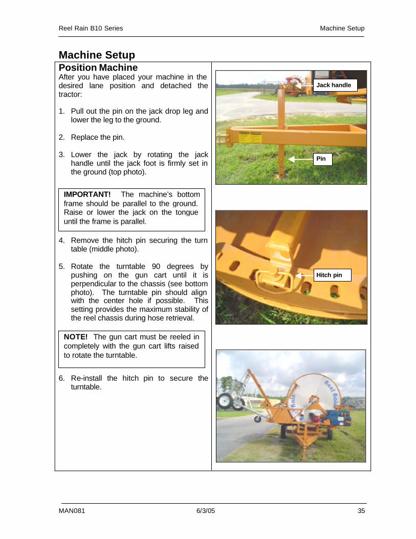
Machine Setup Position Machine After you have placed your machine in the desired lane position and detached the tractor: 1. Pull out the pin on the jack drop leg and
lower the leg to the ground. 2. Replace the pin. 3. Lower the jack by rotating the jack
handle until the jack foot is firmly set in the ground (top photo).
4. Remove the hitch pin securing the turn
table (middle photo). 5. Rotate the turntable 90 degrees by
pushing on the gun cart until it is perpendicular to the chassis (see bottom photo). The turntable pin should align with the center hole if possible. This setting provides the maximum stability of the reel chassis during hose retrieval.
6. Re-install the hitch pin to secure the
turntable.
IMPORTANT! The machine’s bottom frame should be parallel to the ground. Raise or lower the jack on the tongue until the frame is parallel.
Hitch pin
Pin
Jack handle
NOTE! The gun cart must be reeled in completely with the gun cart lifts raised to rotate the turntable.
Machine Set up Reel Rain B10 Series
36 6/3/05 MAN081
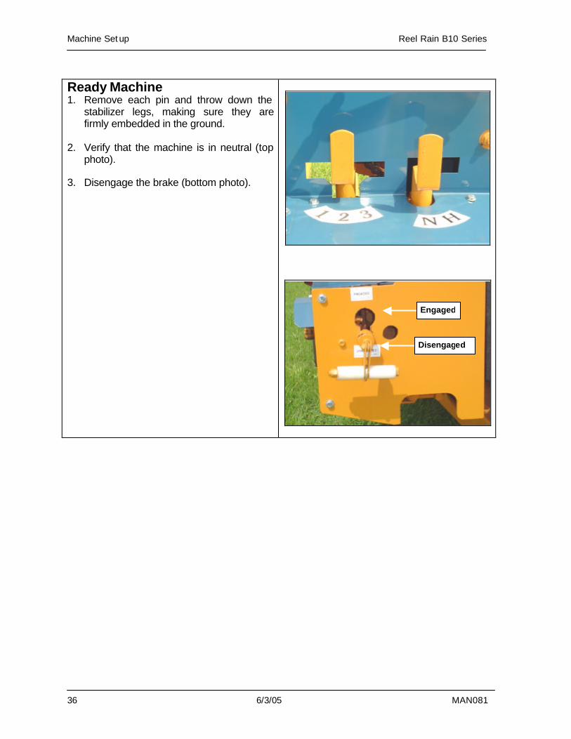
Ready Machine 1. Remove each pin and throw down the
stabilizer legs, making sure they are firmly embedded in the ground.
2. Verify that the machine is in neutral (top
photo). 3. Disengage the brake (bottom photo).
Disengaged
Engaged
Reel Rain B10 Series Machine Setup
MAN081 6/3/05 37
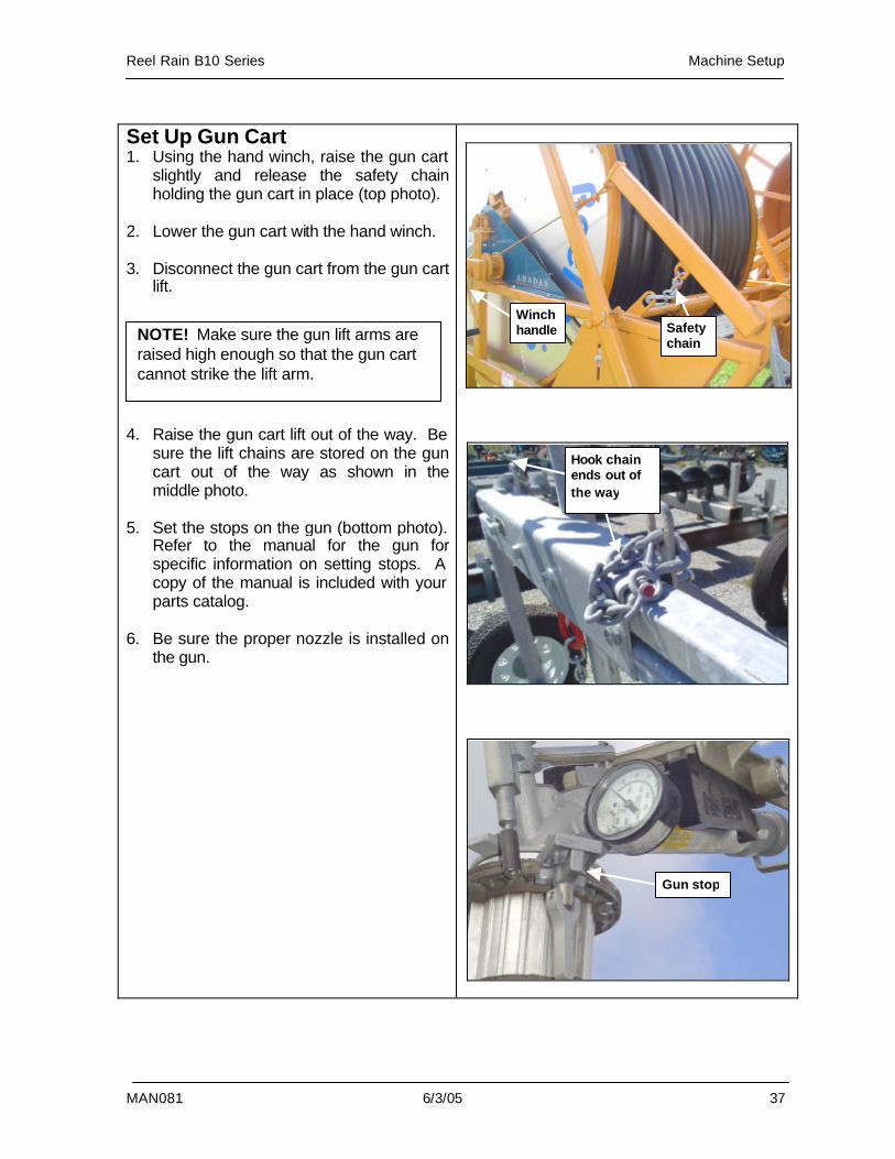
Set Up Gun Cart 1. Using the hand winch, raise the gun cart
slightly and release the safety chain holding the gun cart in place (top photo).
2. Lower the gun cart with the hand winch. 3. Disconnect the gun cart from the gun cart
lift. 4. Raise the gun cart lift out of the way. Be
sure the lift chains are stored on the gun cart out of the way as shown in the middle photo.
5. Set the stops on the gun (bottom photo).
Refer to the manual for the gun for specific information on setting stops. A copy of the manual is included with your parts catalog.
6. Be sure the proper nozzle is installed on
the gun.
NOTE! Make sure the gun lift arms are raised high enough so that the gun cart cannot strike the lift arm.
Winch handle Safety
chain
Gun stop
Hook chain ends out of the way
Machine Set up Reel Rain B10 Series
38 6/3/05 MAN081
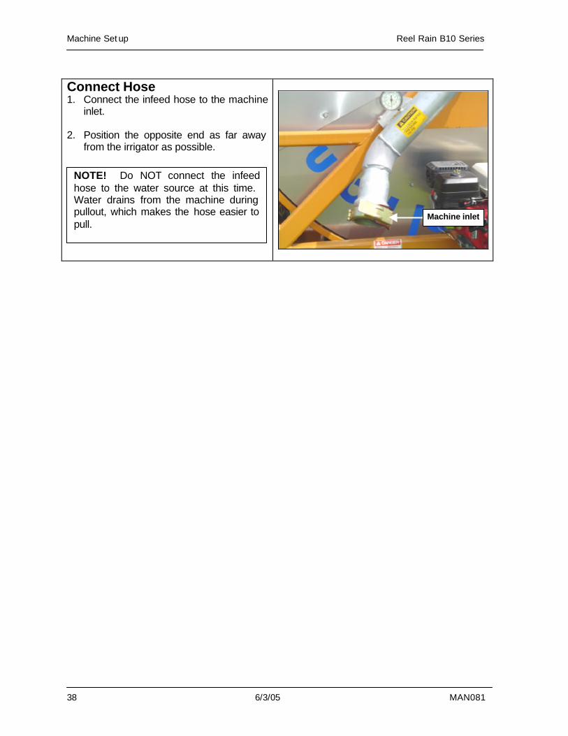
Connect Hose 1. Connect the infeed hose to the machine
inlet. 2. Position the opposite end as far away
from the irrigator as possible.
NOTE! Do NOT connect the infeed hose to the water source at this time. Water drains from the machine during pullout, which makes the hose easier to pull.
Machine inlet
Reel Rain B10 Series Machine Setup
MAN081 6/3/05 39
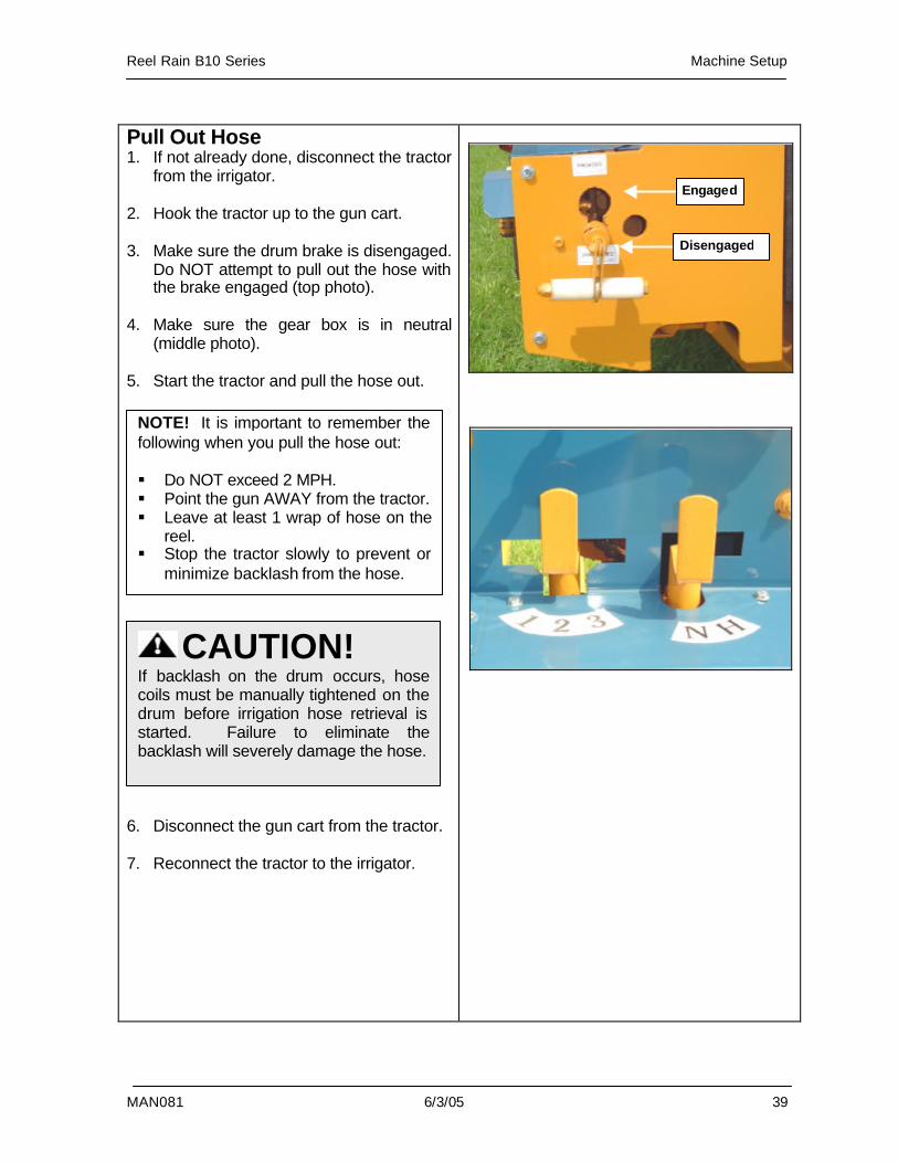
Pull Out Hose 1. If not already done, disconnect the tractor
from the irrigator. 2. Hook the tractor up to the gun cart. 3. Make sure the drum brake is disengaged.
Do NOT attempt to pull out the hose with the brake engaged (top photo).
4. Make sure the gear box is in neutral
(middle photo). 5. Start the tractor and pull the hose out. 6. Disconnect the gun cart from the tractor. 7. Reconnect the tractor to the irrigator.
NOTE! It is important to remember the following when you pull the hose out: § Do NOT exceed 2 MPH. § Point the gun AWAY from the tractor. § Leave at least 1 wrap of hose on the
reel. § Stop the tractor slowly to prevent or
minimize backlash from the hose.
CAUTION! If backlash on the drum occurs, hose coils must be manually tightened on the drum before irrigation hose retrieval is started. Failure to eliminate the backlash will severely damage the hose.
Disengaged
Engaged
Machine Set up Reel Rain B10 Series
40 6/3/05 MAN081
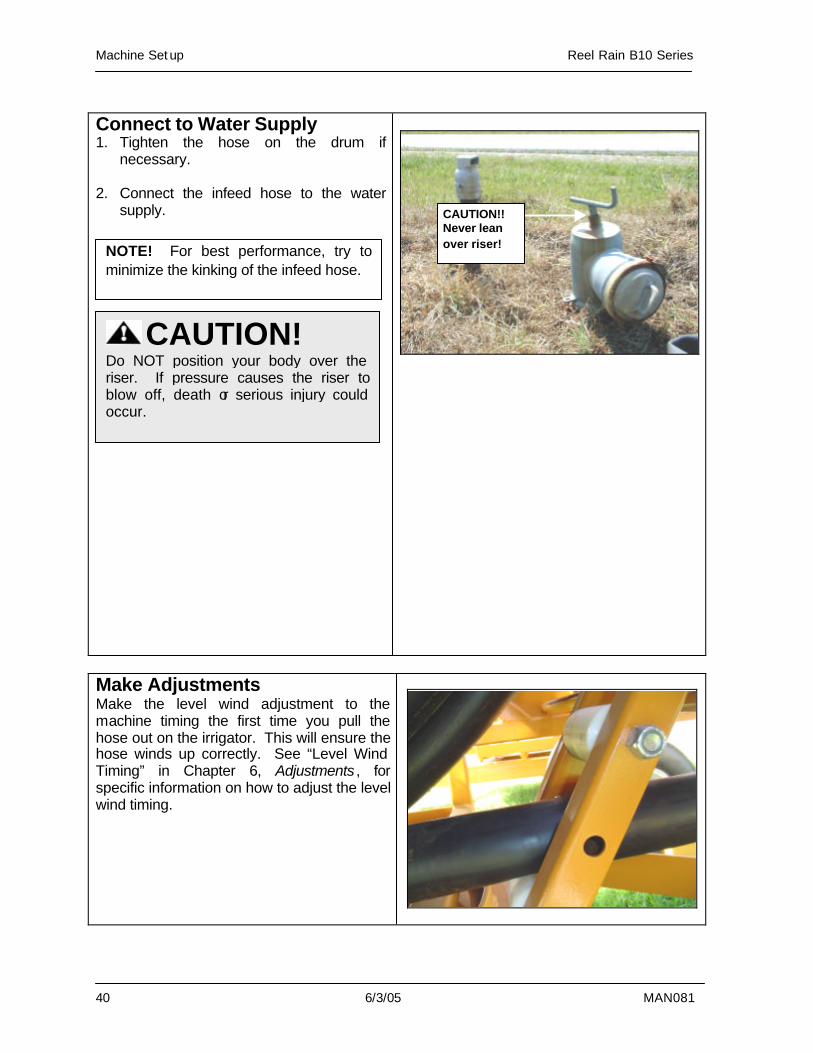
Connect to Water Supply 1. Tighten the hose on the drum if
necessary. 2. Connect the infeed hose to the water
supply.
Make Adjustments Make the level wind adjustment to the machine timing the first time you pull the hose out on the irrigator. This will ensure the hose winds up correctly. See “Level Wind Timing” in Chapter 6, Adjustments , for specific information on how to adjust the level wind timing.
NOTE! For best performance, try to minimize the kinking of the infeed hose.
CAUTION!! Never lean over riser!
CAUTION! Do NOT position your body over the riser. If pressure causes the riser to blow off, death or serious injury could occur.
Reel Rain B10 Series Operation
MAN081 6/3/05 41
5. Operation
Machine Operation ..................................42 Pre-Operation Checklist ......................42 Automatic Cutoff Bar............................43 3-Speed Transmission.........................44 Speed Chart.........................................44 Operation .............................................46 Shift Gears During a Pull .....................51
Run Termination ......................................53 End the Run.........................................54 Rewind Hose with PTO Shaft..............57
Operation Reel Rain B10 Series
42 6/3/05 MAN081
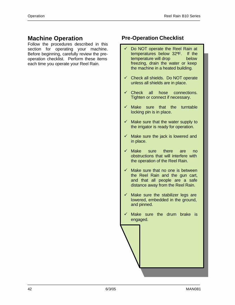
Machine Operation Follow the procedures described in this section for operating your machine. Before beginning, carefully review the pre-operation checklist. Perform these items each time you operate your Reel Rain.
Pre-Operation Checklist
ü Do NOT operate the Reel Rain at temperatures below 32ºF. If the temperature will drop below freezing, drain the water or keep the machine in a heated building.
ü Check all shields. Do NOT operate
unless all shields are in place. ü Check all hose connections.
Tighten or connect if necessary. ü Make sure that the turntable
locking pin is in place. ü Make sure that the water supply to
the irrigator is ready for operation. ü Make sure the jack is lowered and
in place. ü Make sure there are no
obstructions that will interfere with the operation of the Reel Rain.
ü Make sure that no one is between
the Reel Rain and the gun cart, and that all people are a safe distance away from the Reel Rain.
ü Make sure the stabilizer legs are
lowered, embedded in the ground, and pinned.
ü Make sure the drum brake is
engaged.
Reel Rain B10 Series Operation
MAN081 6/3/05 43
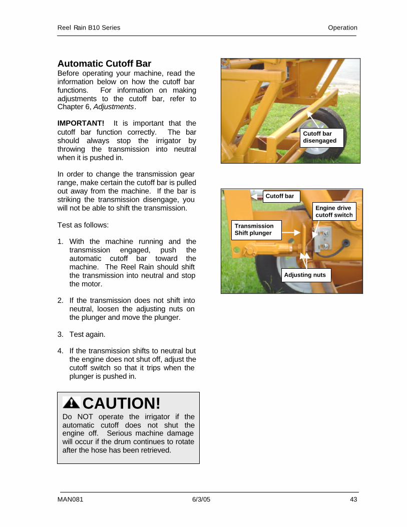
Automatic Cutoff Bar Before operating your machine, read the information below on how the cutoff bar functions. For information on making adjustments to the cutoff bar, refer to Chapter 6, Adjustments. IMPORTANT! It is important that the cutoff bar function correctly. The bar should always stop the irrigator by throwing the transmission into neutral when it is pushed in. In order to change the transmission gear range, make certain the cutoff bar is pulled out away from the machine. If the bar is striking the transmission disengage, you will not be able to shift the transmission. Test as follows: 1. With the machine running and the
transmission engaged, push the automatic cutoff bar toward the machine. The Reel Rain should shift the transmission into neutral and stop the motor.
2. If the transmission does not shift into
neutral, loosen the adjusting nuts on the plunger and move the plunger.
3. Test again. 4. If the transmission shifts to neutral but
the engine does not shut off, adjust the cutoff switch so that it trips when the plunger is pushed in.
CAUTION! Do NOT operate the irrigator if the automatic cutoff does not shut the engine off. Serious machine damage will occur if the drum continues to rotate after the hose has been retrieved.
Adjusting nuts
Cutoff bar
Transmission Shift plunger
Engine drive cutoff switch
Cutoff bar disengaged
Operation Reel Rain B10 Series
44 6/3/05 MAN081
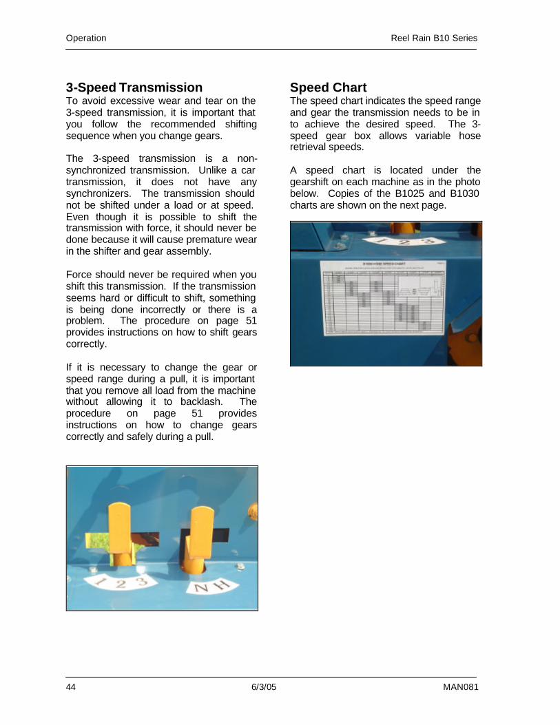
3-Speed Transmission To avoid excessive wear and tear on the 3-speed transmission, it is important that you follow the recommended shifting sequence when you change gears. The 3-speed transmission is a non-synchronized transmission. Unlike a car transmission, it does not have any synchronizers. The transmission should not be shifted under a load or at speed. Even though it is possible to shift the transmission with force, it should never be done because it will cause premature wear in the shifter and gear assembly. Force should never be required when you shift this transmission. If the transmission seems hard or difficult to shift, something is being done incorrectly or there is a problem. The procedure on page 51 provides instructions on how to shift gears correctly. If it is necessary to change the gear or speed range during a pull, it is important that you remove all load from the machine without allowing it to backlash. The procedure on page 51 provides instructions on how to change gears correctly and safely during a pull.
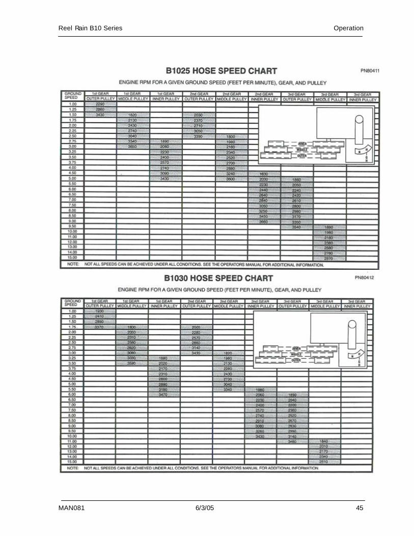
Speed Chart The speed chart indicates the speed range and gear the transmission needs to be in to achieve the desired speed. The 3-speed gear box allows variable hose retrieval speeds. A speed chart is located under the gearshift on each machine as in the photo below. Copies of the B1025 and B1030 charts are shown on the next page.
Reel Rain B10 Series Operation
MAN081 6/3/05 45
Operation Reel Rain B10 Series
46 6/3/05 MAN081
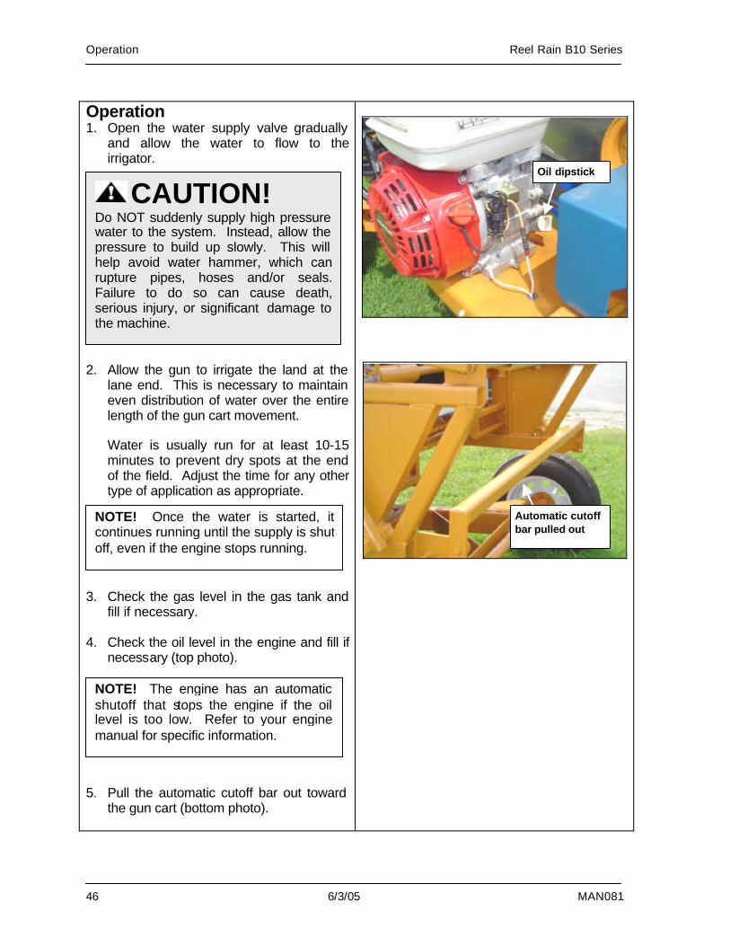
Operation 1. Open the water supply valve gradually
and allow the water to flow to the irrigator.
2. Allow the gun to irrigate the land at the
lane end. This is necessary to maintain even distribution of water over the entire length of the gun cart movement.
Water is usually run for at least 10-15 minutes to prevent dry spots at the end of the field. Adjust the time for any other type of application as appropriate.
3. Check the gas level in the gas tank and fill if necessary.
4. Check the oil level in the engine and fill if
necessary (top photo). 5. Pull the automatic cutoff bar out toward
the gun cart (bottom photo).
CAUTION! Do NOT suddenly supply high pressure water to the system. Instead, allow the pressure to build up slowly. This will help avoid water hammer, which can rupture pipes, hoses and/or seals. Failure to do so can cause death, serious injury, or significant damage to the machine.
NOTE! Once the water is started, it continues running until the supply is shut off, even if the engine stops running.
Oil dipstick
NOTE! The engine has an automatic shutoff that stops the engine if the oil level is too low. Refer to your engine manual for specific information.
Automatic cutoff bar pulled out
Reel Rain B10 Series Operation
MAN081 6/3/05 47
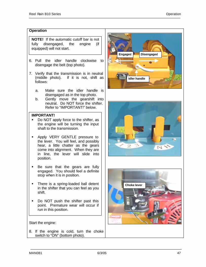
Operation 6. Pull the idler handle clockwise to
disengage the belt (top photo). 7. Verify that the transmission is in neutral
(middle photo). If it is not, shift as follows:
a. Make sure the idler handle is
disengaged as in the top photo. b. Gently move the gearshift into
neutral. Do NOT force the shifter. Refer to “IMPORTANT!” below.
Start the engine: 8. If the engine is cold, turn the choke
switch to “ON” (bottom photo).
NOTE! If the automatic cutoff bar is not fully disengaged, the engine (if equipped) will not start.
Disengaged Engaged
Idler handle
Choke lever
IMPORTANT! § Do NOT apply force to the shifter, as
the engine will be turning the input shaft to the transmission.
§ Apply VERY GENTLE pressure to
the lever. You will feel, and possibly hear, a little chatter as the gears come into alignment. When they are in line, the lever will slide into position.
§ Be sure that the gears are fully
engaged. You should feel a definite stop when it is in position.
§ There is a spring-loaded ball detent
in the shifter that you can feel as you shift.
§ Do NOT push the shifter past this
point. Premature wear will occur if run in this position.
Operation Reel Rain B10 Series
48 6/3/05 MAN081
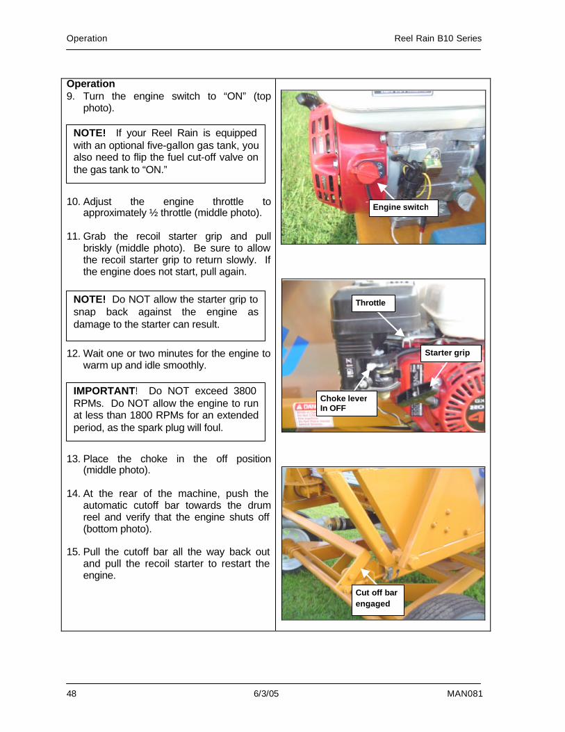
Operation 9. Turn the engine switch to “ON” (top
photo). 10. Adjust the engine throttle to
approximately ½ throttle (middle photo). 11. Grab the recoil starter grip and pull
briskly (middle photo). Be sure to allow the recoil starter grip to return slowly. If the engine does not start, pull again.
12. Wait one or two minutes for the engine to
warm up and idle smoothly. 13. Place the choke in the off position
(middle photo). 14. At the rear of the machine, push the
automatic cutoff bar towards the drum reel and verify that the engine shuts off (bottom photo).
15. Pull the cutoff bar all the way back out
and pull the recoil starter to restart the engine.
NOTE! If your Reel Rain is equipped with an optional five-gallon gas tank, you also need to flip the fuel cut-off valve on the gas tank to “ON.”
Throttle
Choke lever In OFF
Starter grip
Engine switch
NOTE! Do NOT allow the starter grip to snap back against the engine as damage to the starter can result.
IMPORTANT! Do NOT exceed 3800 RPMs. Do NOT allow the engine to run at less than 1800 RPMs for an extended period, as the spark plug will foul.
Cut off bar engaged
Reel Rain B10 Series Operation
MAN081 6/3/05 49
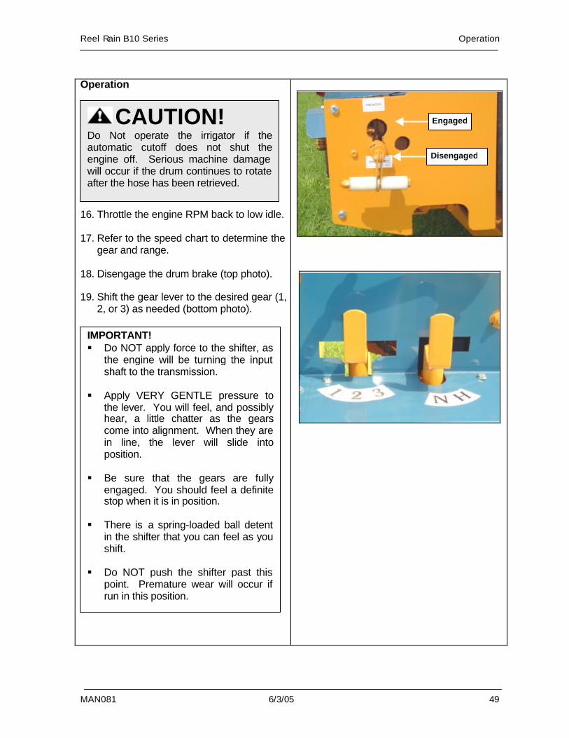
Operation 16. Throttle the engine RPM back to low idle. 17. Refer to the speed chart to determine the
gear and range. 18. Disengage the drum brake (top photo). 19. Shift the gear lever to the desired gear (1,
2, or 3) as needed (bottom photo).
CAUTION! Do Not operate the irrigator if the automatic cutoff does not shut the engine off. Serious machine damage will occur if the drum continues to rotate after the hose has been retrieved.
IMPORTANT! § Do NOT apply force to the shifter, as
the engine will be turning the input shaft to the transmission.
§ Apply VERY GENTLE pressure to
the lever. You will feel, and possibly hear, a little chatter as the gears come into alignment. When they are in line, the lever will slide into position.
§ Be sure that the gears are fully
engaged. You should feel a definite stop when it is in position.
§ There is a spring-loaded ball detent
in the shifter that you can feel as you shift.
§ Do NOT push the shifter past this
point. Premature wear will occur if run in this position.
Disengaged
Engaged
Operation Reel Rain B10 Series
50 6/3/05 MAN081
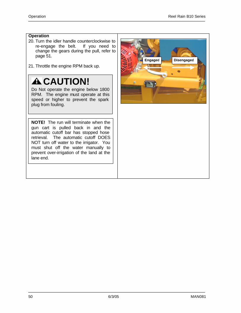
Operation 20. Turn the idler handle counterclockwise to
re-engage the belt. If you need to change the gears during the pull, refer to page 51.
21. Throttle the engine RPM back up.
Disengaged Engaged
CAUTION! Do Not operate the engine below 1800 RPM. The engine must operate at this speed or higher to prevent the spark plug from fouling.
NOTE! The run will terminate when the gun cart is pulled back in and the automatic cutoff bar has stopped hose retrieval. The automatic cutoff DOES NOT turn off water to the irrigator. You must shut off the water manually to prevent over-irrigation of the land at the lane end.
Reel Rain B10 Series Operation
MAN081 6/3/05 51
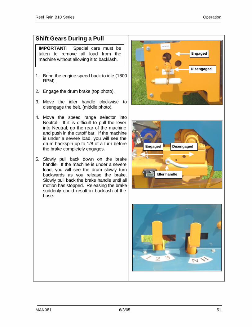
Shift Gears During a Pull 1. Bring the engine speed back to idle (1800
RPM). 2. Engage the drum brake (top photo). 3. Move the idler handle clockwise to
disengage the belt. (middle photo). 4. Move the speed range selector into
Neutral. If it is difficult to pull the lever into Neutral, go the rear of the machine and push in the cutoff bar. If the machine is under a severe load, you will see the drum backspin up to 1/8 of a turn before the brake completely engages.
5. Slowly pull back down on the brake
handle. If the machine is under a severe load, you will see the drum slowly turn backwards as you release the brake. Slowly pull back the brake handle until all motion has stopped. Releasing the brake suddenly could result in backlash of the hose.
IMPORTANT! Special care must be taken to remove all load from the machine without allowing it to backlash.
Disengaged
Engaged
Disengaged Engaged
Idler handle
Operation Reel Rain B10 Series
52 6/3/05 MAN081
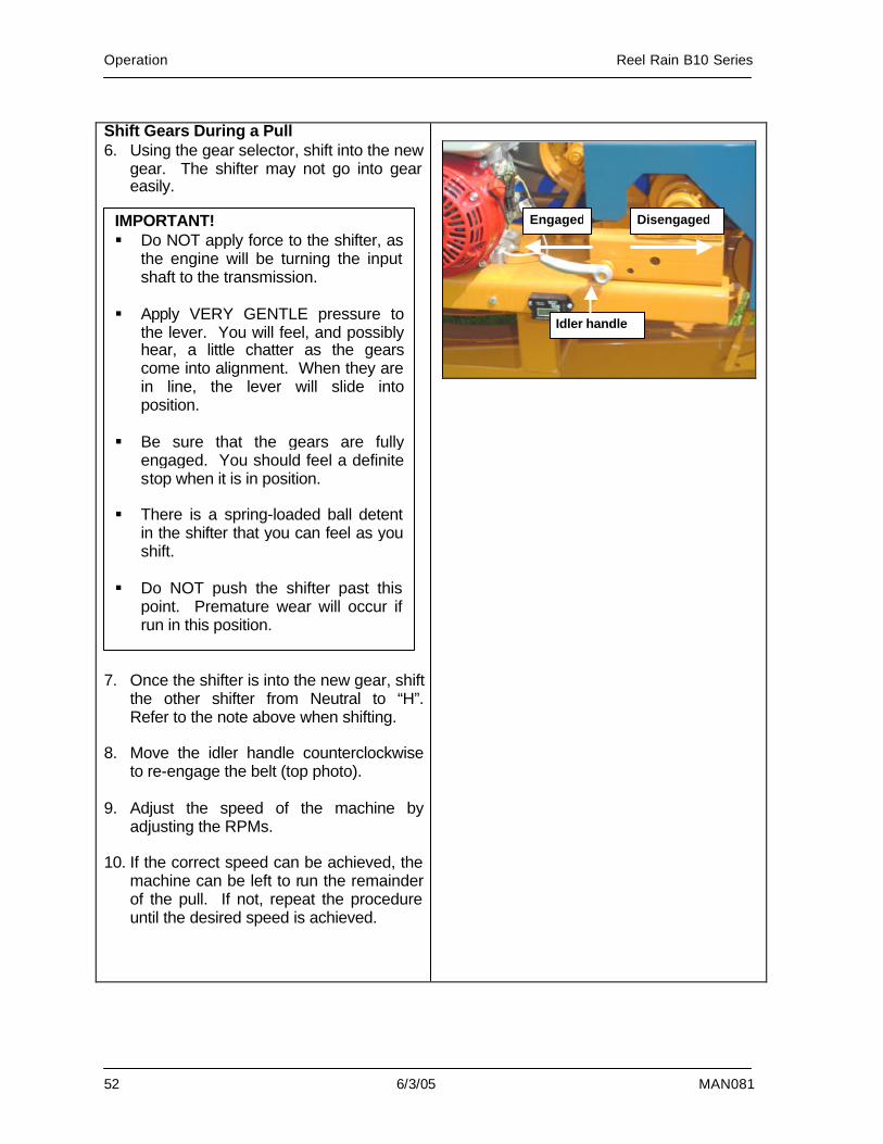
Shift Gears During a Pull 6. Using the gear selector, shift into the new
gear. The shifter may not go into gear easily.
7. Once the shifter is into the new gear, shift
the other shifter from Neutral to “H”. Refer to the note above when shifting.
8. Move the idler handle counterclockwise
to re-engage the belt (top photo). 9. Adjust the speed of the machine by
adjusting the RPMs. 10. If the correct speed can be achieved, the
machine can be left to run the remainder of the pull. If not, repeat the procedure until the desired speed is achieved.
IMPORTANT! § Do NOT apply force to the shifter, as
the engine will be turning the input shaft to the transmission.
§ Apply VERY GENTLE pressure to
the lever. You will feel, and possibly hear, a little chatter as the gears come into alignment. When they are in line, the lever will slide into position.
§ Be sure that the gears are fully
engaged. You should feel a definite stop when it is in position.
§ There is a spring-loaded ball detent
in the shifter that you can feel as you shift.
§ Do NOT push the shifter past this
point. Premature wear will occur if run in this position.
Disengaged Engaged
Idler handle
Reel Rain B10 Series Operation
MAN081 6/3/05 53
Run Termination The time needed to complete a run depends on the retrieval speed and hose length. Usually, the run is terminated when the gun cart has been pulled all the way in and the automatic cutoff bar has stopped the hose retrieval. The procedure for ending a run starts on page 54. If you choose to stop the irrigator before the gun cart is all the way in, you can use a PTO shaft to rewind the remaining hose.
Instructions for using a PTO shaft to rewind the hose begin on page 57. You can use the optional PTO shaft that is available with the Reel Rain or any other PTO shaft that is four feet or more collapsed.
IMPORTANT! Do NOT use a PTO shaft that is less than four feet when collapsed. A shorter one will cause the load to be uneven and will put pressure on the gearbox housing.
Operation Reel Rain B10 Series
54 6/3/05 MAN081
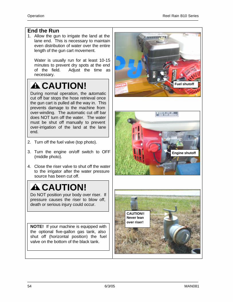
End the Run 1. Allow the gun to irrigate the land at the
lane end. This is necessary to maintain even distribution of water over the entire length of the gun cart movement.
Water is usually run for at least 10-15 minutes to prevent dry spots at the end of the field. Adjust the time as necessary.
2. Turn off the fuel valve (top photo). 3. Turn the engine on/off switch to OFF
(middle photo). 4. Close the riser valve to shut off the water
to the irrigator after the water pressure source has been cut off.
CAUTION! During normal operation, the automatic cut off bar stops the hose retrieval once the gun cart is pulled all the way in. This prevents damage to the machine from over-winding. The automatic cut off bar does NOT turn off the water. The water must be shut off manually to prevent over-irrigation of the land at the lane end.
CAUTION! Do NOT position your body over riser. If pressure causes the riser to blow off, death or serious injury could occur.
Fuel shutoff
Engine shutoff
CAUTION!! Never lean over riser!
NOTE! If your machine is equipped with the optional five-gallon gas tank, also shut off (horizontal position) the fuel valve on the bottom of the black tank.
Reel Rain B10 Series Operation
MAN081 6/3/05 55
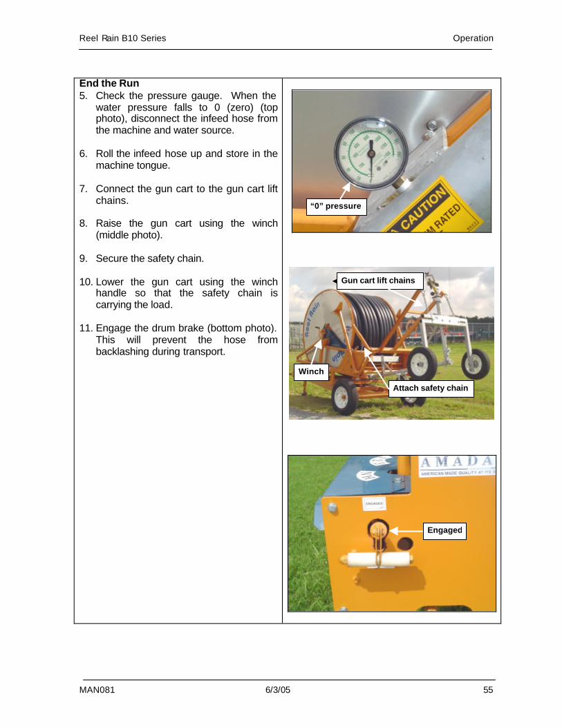
End the Run 5. Check the pressure gauge. When the
water pressure falls to 0 (zero) (top photo), disconnect the infeed hose from the machine and water source.
6. Roll the infeed hose up and store in the
machine tongue. 7. Connect the gun cart to the gun cart lift
chains. 8. Raise the gun cart using the winch
(middle photo). 9. Secure the safety chain. 10. Lower the gun cart using the winch
handle so that the safety chain is carrying the load.
11. Engage the drum brake (bottom photo).
This will prevent the hose from backlashing during transport.
Gun cart lift chains
“0” pressure
Winch
Attach safety chain
Engaged
Operation Reel Rain B10 Series
56 6/3/05 MAN081
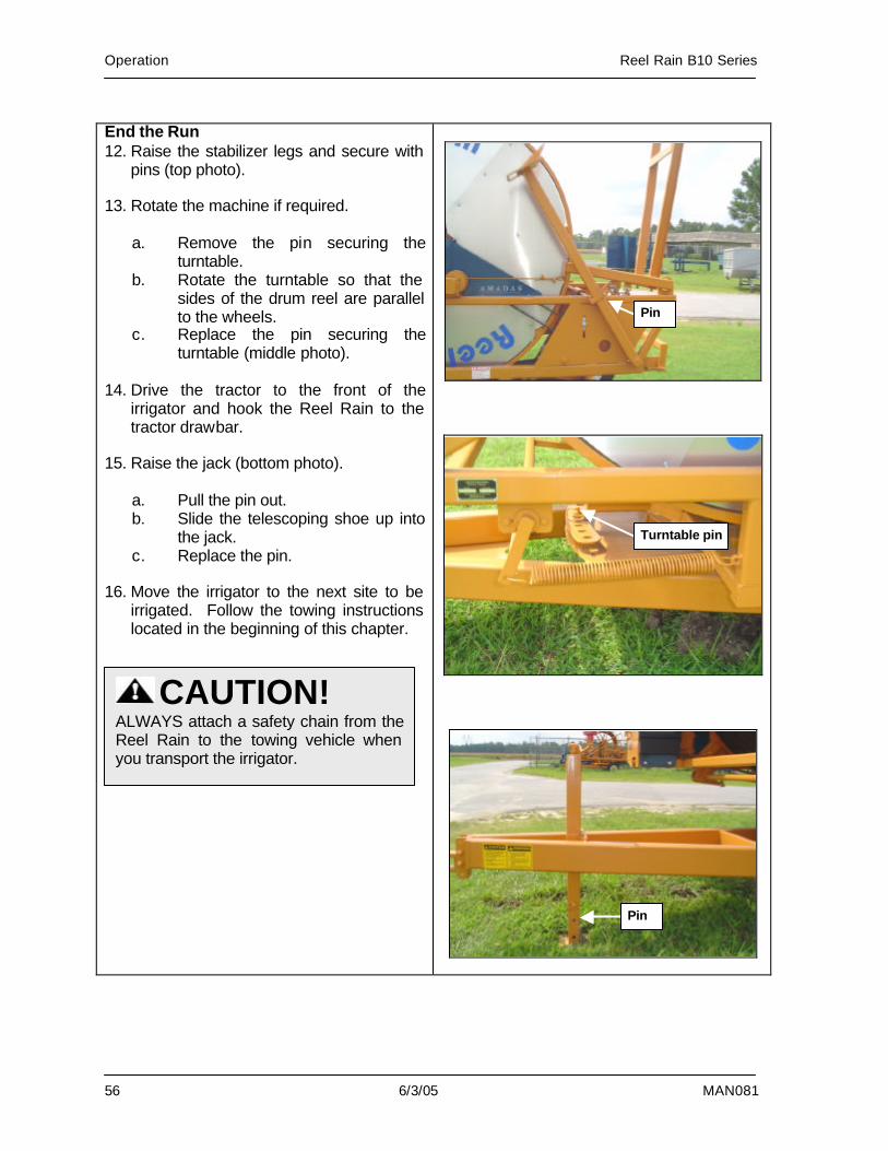
End the Run 12. Raise the stabilizer legs and secure with
pins (top photo). 13. Rotate the machine if required.
a. Remove the pin securing the turntable.
b. Rotate the turntable so that the sides of the drum reel are parallel to the wheels.
c. Replace the pin securing the turntable (middle photo).
14. Drive the tractor to the front of the
irrigator and hook the Reel Rain to the tractor drawbar.
15. Raise the jack (bottom photo).
a. Pull the pin out. b. Slide the telescoping shoe up into
the jack. c. Replace the pin.
16. Move the irrigator to the next site to be
irrigated. Follow the towing instructions located in the beginning of this chapter.
CAUTION! ALWAYS attach a safety chain from the Reel Rain to the towing vehicle when you transport the irrigator.
Turntable pin
Pin
Pin
Reel Rain B10 Series Operation
MAN081 6/3/05 57
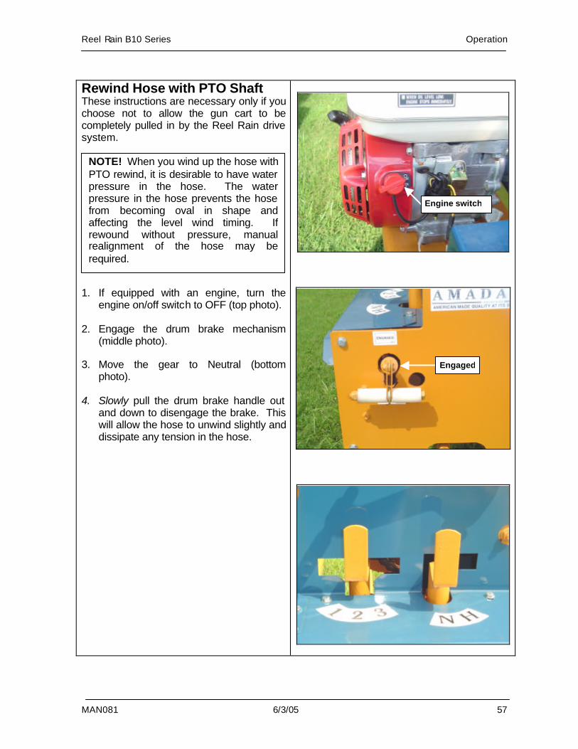
Rewind Hose with PTO Shaft These instructions are necessary only if you choose not to allow the gun cart to be completely pulled in by the Reel Rain drive system. 1. If equipped with an engine, turn the
engine on/off switch to OFF (top photo). 2. Engage the drum brake mechanism
(middle photo). 3. Move the gear to Neutral (bottom
photo). 4. Slowly pull the drum brake handle out
and down to disengage the brake. This will allow the hose to unwind slightly and dissipate any tension in the hose.
NOTE! When you wind up the hose with PTO rewind, it is desirable to have water pressure in the hose. The water pressure in the hose prevents the hose from becoming oval in shape and affecting the level wind timing. If rewound without pressure, manual realignment of the hose may be required.
Engine switch
Engaged
Operation Reel Rain B10 Series
58 6/3/05 MAN081
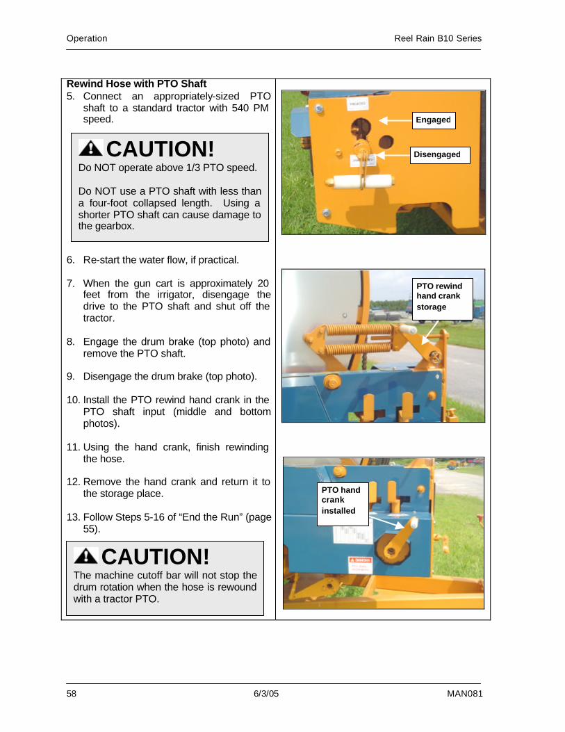
Rewind Hose with PTO Shaft 5. Connect an appropriately-sized PTO
shaft to a standard tractor with 540 PM speed.
6. Re-start the water flow, if practical. 7. When the gun cart is approximately 20
feet from the irrigator, disengage the drive to the PTO shaft and shut off the tractor.
8. Engage the drum brake (top photo) and
remove the PTO shaft. 9. Disengage the drum brake (top photo). 10. Install the PTO rewind hand crank in the
PTO shaft input (middle and bottom photos).
11. Using the hand crank, finish rewinding
the hose. 12. Remove the hand crank and return it to
the storage place. 13. Follow Steps 5-16 of “End the Run” (page
55).
CAUTION! Do NOT operate above 1/3 PTO speed. Do NOT use a PTO shaft with less than a four-foot collapsed length. Using a shorter PTO shaft can cause damage to the gearbox.
PTO rewind hand crank storage
PTO hand crank installed
Disengaged
Engaged
CAUTION! The machine cutoff bar will not stop the drum rotation when the hose is rewound with a tractor PTO.
Reel Rain B10 Series Adjustments
MAN081 6/3/05 59
6. Adjustments
Overview..................................................60 Automatic Shutoff ....................................60 Compensation Adjustment ......................61 Level Wind Timing ...................................62 Gun Carts ................................................64
Drain.....................................................64 Main Wheels ........................................65 Nose Wheel .........................................65 Gun Speed...........................................65 Gun ......................................................66 Nozzles ................................................67 Tension Adjustments ...........................68
Adjustments Reel Rain B10 Series
60 6/3/05 MAN081
Overview This chapter provides information for making basic adjustments on the Reel Rain after it is put into operation. Adjustments needed to initially set up the Reel Rain are described in the Chapter 2, Preparation. Information needed to set up the Reel Rain is provided in Chapter 4, Machine Setup. Chapter 5, Operation, provides information on running the Reel Rain; information for lubrication, maintenance, and storage of the Reel Rain is provided in Chapter 7, Maintenance.
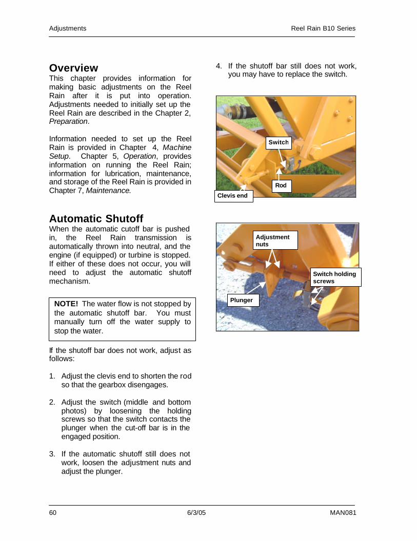
Automatic Shutoff When the automatic cutoff bar is pushed in, the Reel Rain transmission is automatically thrown into neutral, and the engine (if equipped) or turbine is stopped. If either of these does not occur, you will need to adjust the automatic shutoff mechanism. If the shutoff bar does not work, adjust as follows: 1. Adjust the clevis end to shorten the rod
so that the gearbox disengages. 2. Adjust the switch (middle and bottom
photos) by loosening the holding screws so that the switch contacts the plunger when the cut-off bar is in the engaged position.
3. If the automatic shutoff still does not
work, loosen the adjustment nuts and adjust the plunger.
4. If the shutoff bar still does not work, you may have to replace the switch.
NOTE! The water flow is not stopped by the automatic shutoff bar. You must manually turn off the water supply to stop the water.
Switch holding screws
Plunger
Adjustment nuts
Switch
Rod
Clevis end
Reel Rain B10 Series Adjustments
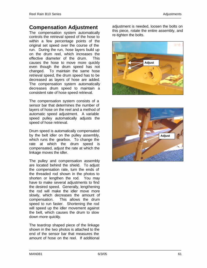
MAN081 6/3/05 61
Compensation Adjustment The compensation system automatically controls the retrieval speed of the hose to within a few percentage points of the original set speed over the course of the run. During the run, hose layers build up on the drum reel, which increases the effective diameter of the drum. This causes the hose to move more quickly even though the drum speed has not changed. To maintain the same hose retrieval speed, the drum speed has to be decreased as layers of hose are added. The compensation system automatically decreases drum speed to maintain a consistent rate of hose speed retrieval. The compensation system consists of a sensor bar that determines the number of layers of hose on the reel and a method of automatic speed adjustment. A variable speed pulley automatically adjusts the speed of hose retrieval. Drum speed is automatically compensated by the belt idler on the pulley assembly, which runs the gearbox. To change the rate at which the drum speed is compensated, adjust the rate at which the linkage moves the idler. The pulley and compensation assembly are located behind the shield. To adjust the compensation rate, turn the ends of the threaded rod shown in the photos to shorten or lengthen the rod. You may have to make several adjustments to find the desired speed. Generally, lengthening the rod will make the idler move more slowly, which decreases the amount of compensation. This allows the drum speed to run faster. Shortening the rod will speed up the idler movement against the belt, which causes the drum to slow down more quickly. The teardrop shaped piece of the linkage shown in the two photos is attached to the end of the sensor bar that measures the amount of hose on the reel. If additional
adjustment is needed, loosen the bolts on this piece, rotate the entire assembly, and re-tighten the bolts.
Adjust
Adjust
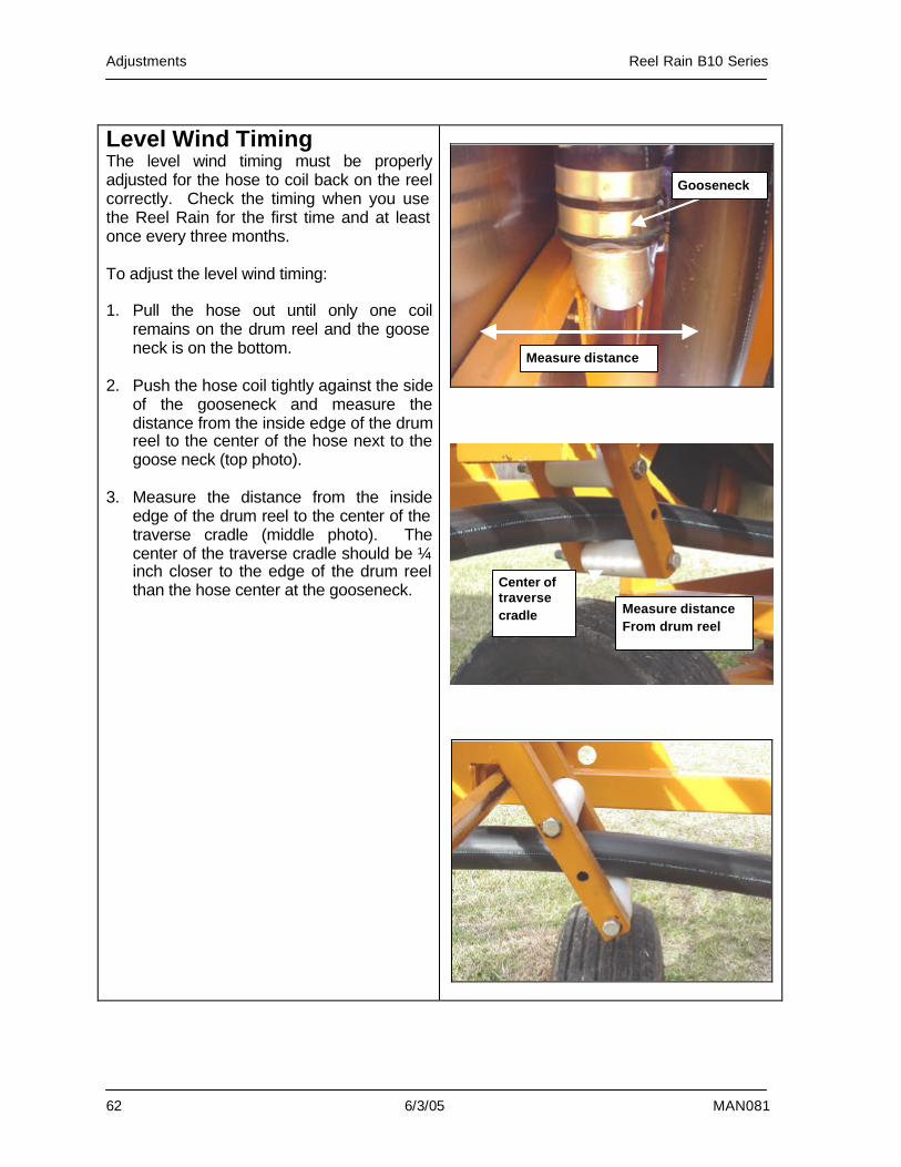
Adjustments Reel Rain B10 Series
62 6/3/05 MAN081
Level Wind Timing The level wind timing must be properly adjusted for the hose to coil back on the reel correctly. Check the timing when you use the Reel Rain for the first time and at least once every three months. To adjust the level wind timing: 1. Pull the hose out until only one coil
remains on the drum reel and the goose neck is on the bottom.
2. Push the hose coil tightly against the side
of the gooseneck and measure the distance from the inside edge of the drum reel to the center of the hose next to the goose neck (top photo).
3. Measure the distance from the inside
edge of the drum reel to the center of the traverse cradle (middle photo). The center of the traverse cradle should be ¼ inch closer to the edge of the drum reel than the hose center at the gooseneck.
Gooseneck
Measure distance
Center of traverse cradle Measure distance
From drum reel
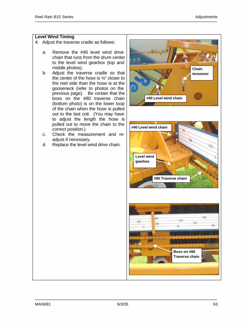
Reel Rain B10 Series Adjustments
MAN081 6/3/05 63
Level Wind Timing 4. Adjust the traverse cradle as follows:
a. Remove the #40 level wind drive chain that runs from the drum center to the level wind gearbox (top and middle photos).
b. Adjust the traverse cradle so that the center of the hose is ¼“ closer to the reel side than the hose is at the gooseneck (refer to photos on the previous page). Be certain that the boss on the #80 traverse chain (bottom photo) is on the lower loop of the chain when the hose is pulled out to the last coil. (You may have to adjust the length the hose is pulled out to move the chain to the correct position.)
c. Check the measurement and re-adjust if necessary.
d. Replace the level wind drive chain.
#40 Level wind chain
#80 Traverse chain
#40 Level wind chain
Level wind gearbox
Boss on #80 Traverse chain
Chain tensioner
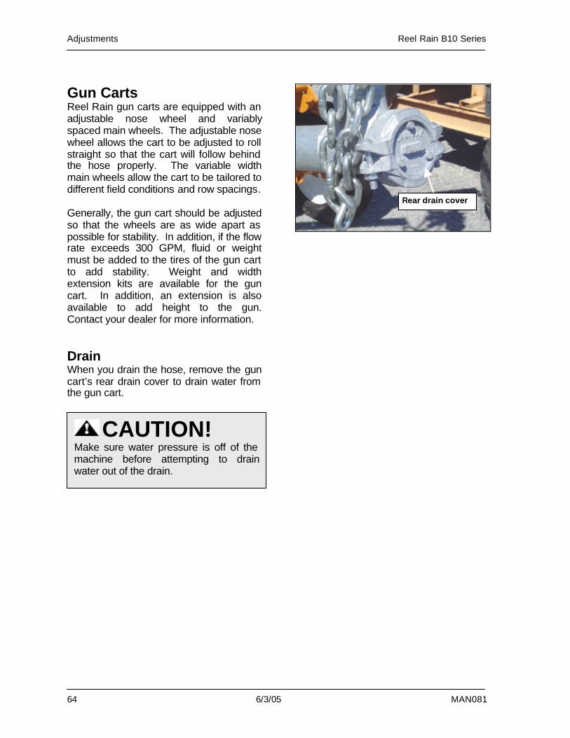
Adjustments Reel Rain B10 Series
64 6/3/05 MAN081
Gun Carts Reel Rain gun carts are equipped with an adjustable nose wheel and variably spaced main wheels. The adjustable nose wheel allows the cart to be adjusted to roll straight so that the cart will follow behind the hose properly. The variable width main wheels allow the cart to be tailored to different field conditions and row spacings. Generally, the gun cart should be adjusted so that the wheels are as wide apart as possible for stability. In addition, if the flow rate exceeds 300 GPM, fluid or weight must be added to the tires of the gun cart to add stability. Weight and width extension kits are available for the gun cart. In addition, an extension is also available to add height to the gun. Contact your dealer for more information. Drain When you drain the hose, remove the gun cart’s rear drain cover to drain water from the gun cart.
Rear drain cover
CAUTION! Make sure water pressure is off of the machine before attempting to drain water out of the drain.
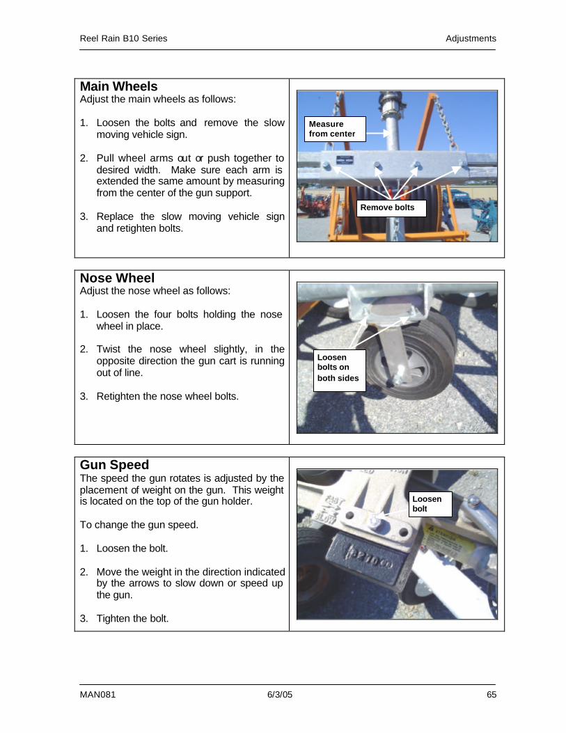
Reel Rain B10 Series Adjustments
MAN081 6/3/05 65
Main Wheels Adjust the main wheels as follows: 1. Loosen the bolts and remove the slow
moving vehicle sign. 2. Pull wheel arms out or push together to
desired width. Make sure each arm is extended the same amount by measuring from the center of the gun support.
3. Replace the slow moving vehicle sign
and retighten bolts.
Nose Wheel Adjust the nose wheel as follows: 1. Loosen the four bolts holding the nose
wheel in place. 2. Twist the nose wheel slightly, in the
opposite direction the gun cart is running out of line.
3. Retighten the nose wheel bolts.
Gun Speed The speed the gun rotates is adjusted by the placement of weight on the gun. This weight is located on the top of the gun holder. To change the gun speed. 1. Loosen the bolt. 2. Move the weight in the direction indicated
by the arrows to slow down or speed up the gun.
3. Tighten the bolt.
Remove bolts
Measure from center
Loosen bolts on both sides
Loosen bolt
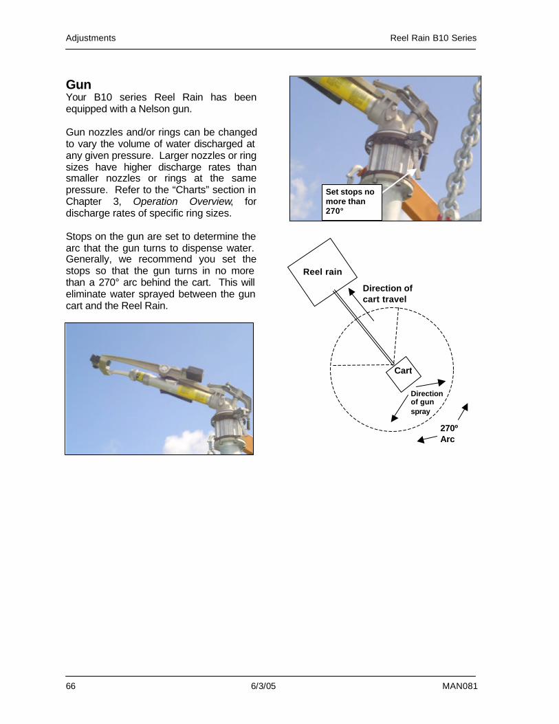
Adjustments Reel Rain B10 Series
66 6/3/05 MAN081
Gun Your B10 series Reel Rain has been equipped with a Nelson gun. Gun nozzles and/or rings can be changed to vary the volume of water discharged at any given pressure. Larger nozzles or ring sizes have higher discharge rates than smaller nozzles or rings at the same pressure. Refer to the “Charts” section in Chapter 3, Operation Overview, for discharge rates of specific ring sizes. Stops on the gun are set to determine the arc that the gun turns to dispense water. Generally, we recommend you set the stops so that the gun turns in no more than a 270° arc behind the cart. This will eliminate water sprayed between the gun cart and the Reel Rain.
Set stops no more than 270°
270º Arc
Reel rain
Direction of cart travel
Cart
Direction of gun spray
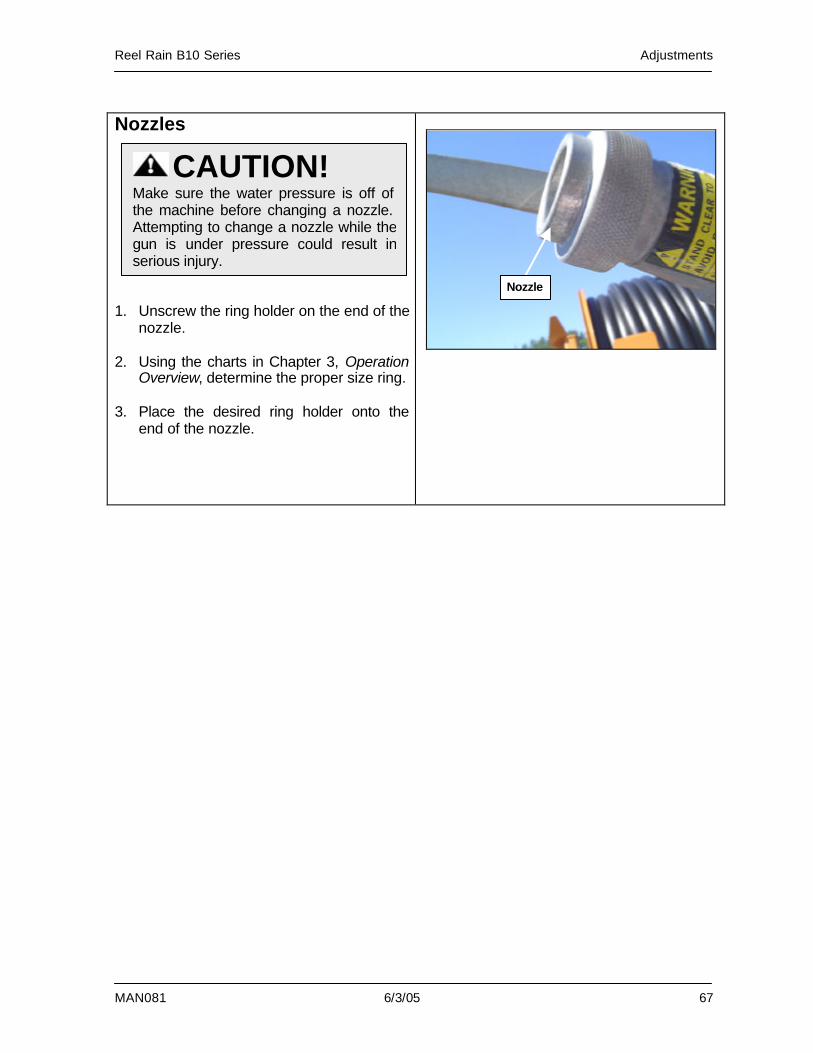
Reel Rain B10 Series Adjustments
MAN081 6/3/05 67
Nozzles 1. Unscrew the ring holder on the end of the
nozzle. 2. Using the charts in Chapter 3, Operation
Overview, determine the proper size ring. 3. Place the desired ring holder onto the
end of the nozzle.
CAUTION! Make sure the water pressure is off of the machine before changing a nozzle. Attempting to change a nozzle while the gun is under pressure could result in serious injury.
Nozzle
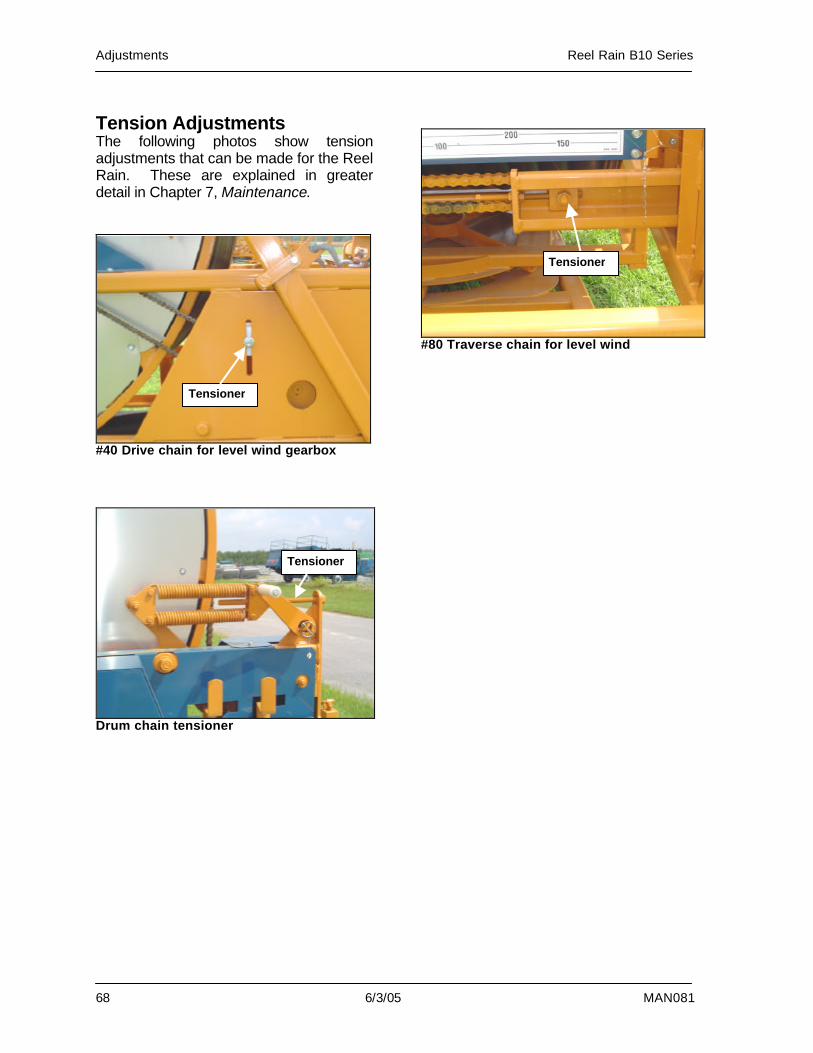
Adjustments Reel Rain B10 Series
68 6/3/05 MAN081
Tension Adjustments The following photos show tension adjustments that can be made for the Reel Rain. These are explained in greater detail in Chapter 7, Maintenance.
#40 Drive chain for level wind gearbox
Drum chain tensioner
#80 Traverse chain for level wind
Tensioner
Tensioner
Tensioner
Reel Rain B10 Series Maintenance
MAN081 6/3/05 69
7. Maintenance
Performing Maintenance .........................70 Lubrication ...............................................71
Chains..................................................72 Drum Support Bearing.........................73 Gearboxes 74 Inlet Spindle Thrust Washer/Inlet Swivel.............................................................75 Primary Shaft Bearing .........................76 Traverse Assembly..............................77 Wheel Bearings/Gun Cart....................78 Wheel Bearings/Reel Rain ..................78
Preventative Maintenance.......................79 Checklist ..............................................79 Drive Chain ..........................................80 Drum Drive Chain ................................80 Engine..................................................81 Level Wind Chain.................................81 Stabilizer Legs .....................................82 Tires .....................................................82 Traverse Chain ....................................83
Off-Season Storage.................................84 Troubleshooting .......................................85
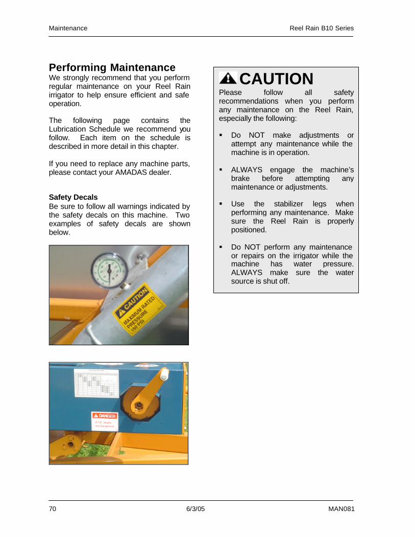
Maintenance Reel Rain B10 Series
70 6/3/05 MAN081
Performing Maintenance We strongly recommend that you perform regular maintenance on your Reel Rain irrigator to help ensure efficient and safe operation. The following page contains the Lubrication Schedule we recommend you follow. Each item on the schedule is described in more detail in this chapter. If you need to replace any machine parts, please contact your AMADAS dealer. Safety Decals Be sure to follow all warnings indicated by the safety decals on this machine. Two examples of safety decals are shown below.
CAUTION Please follow all safety recommendations when you perform any maintenance on the Reel Rain, especially the following: § Do NOT make adjustments or
attempt any maintenance while the machine is in operation.
§ ALWAYS engage the machine’s
brake before attempting any maintenance or adjustments.
§ Use the stabilizer legs when
performing any maintenance. Make sure the Reel Rain is properly positioned.
§ Do NOT perform any maintenance
or repairs on the irrigator while the machine has water pressure. ALWAYS make sure the water source is shut off.
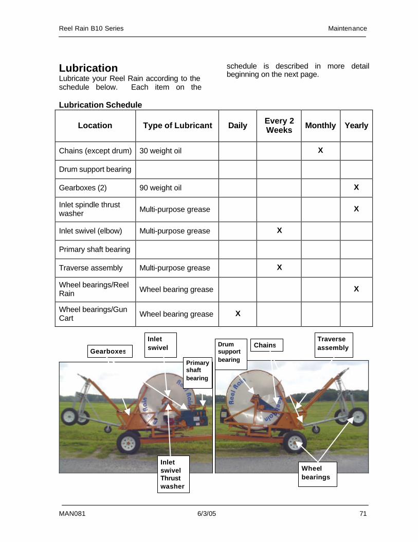
Reel Rain B10 Series Maintenance
MAN081 6/3/05 71
Lubrication Lubricate your Reel Rain according to the schedule below. Each item on the
schedule is described in more detail beginning on the next page.
Lubrication Schedule
Location Type of Lubricant Daily Every 2 Weeks Monthly Yearly
Chains (except drum) 30 weight oil X
Drum support bearing
Gearboxes (2) 90 weight oil X
Inlet spindle thrust washer Multi-purpose grease X
Inlet swivel (elbow) Multi-purpose grease X
Primary shaft bearing
Traverse assembly Multi-purpose grease X
Wheel bearings/Reel Rain Wheel bearing grease X
Wheel bearings/Gun Cart Wheel bearing grease X
Gearboxes
Inlet swivel
Inlet swivel Thrust washer
Traverse assembly
Wheel bearings
Chains
Primary shaft bearing
Drum support bearing
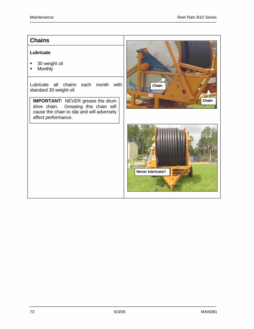
Maintenance Reel Rain B10 Series
72 6/3/05 MAN081
Chains Lubricate § 30 weight oil § Monthly Lubricate all chains each month with standard 30 weight oil.
Never lubricate!!
Chain
IMPORTANT! NEVER grease the drum drive chain. Greasing this chain will cause the chain to slip and will adversely affect performance.
Chain
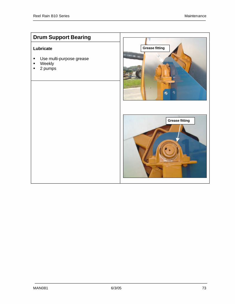
Reel Rain B10 Series Maintenance
MAN081 6/3/05 73
Drum Support Bearing Lubricate § Use multi-purpose grease § Weekly § 2 pumps
Grease fitting
Grease fitting
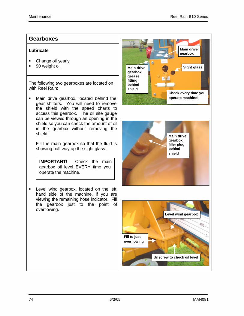
Maintenance Reel Rain B10 Series
74 6/3/05 MAN081
Gearboxes Lubricate § Change oil yearly § 90 weight oil
The following two gearboxes are located on with Reel Rain: § Main drive gearbox, located behind the
gear shifters. You will need to remove the shield with the speed charts to access this gearbox. The oil site gauge can be viewed through an opening in the shield so you can check the amount of oil in the gearbox without removing the shield.
Fill the main gearbox so that the fluid is showing half way up the sight glass.
§ Level wind gearbox, located on the left
hand side of the machine, if you are viewing the remaining hose indicator. Fill the gearbox just to the point of overflowing.
Unscrew to check oil level
Level wind gearbox
Main drive gearbox
Sight glass Main drive gearbox grease fitting behind shield
Main drive gearbox filler plug behind shield
IMPORTANT! Check the main gearbox oil level EVERY time you operate the machine.
Fill to just overflowing
Check every time you operate machine!

Reel Rain B10 Series Maintenance
MAN081 6/3/05 75
Inlet Spindle Thrust Washer/Inlet Swivel Lubricate § Weekly § Use multi-purpose grease § 6 pumps in plastic block weekly There are two lubrication applications on the inlet plumbing: § The inlet swivel (or elbow) has a grease
fitting that needs to be greased weekly. It is important that you maintain this fitting to prevent the bearings from rusting, which will cause leaking and prematurely wear the plumbing.
§ The inlet spindle thrust washer tends to
dry out while the Reel Rain is being stored for the winter. Therefore, it is important that you pack the spindle and bearing with grease each season before you put the Reel Rain back into service. These items are located behind the inlet plumbing. Take care when packing grease into these items, as too much force can unseat the snap ring.
Grease fitting
Inlet spindle thrust washer located behind plumbing
6 pumps in plastic block weekly
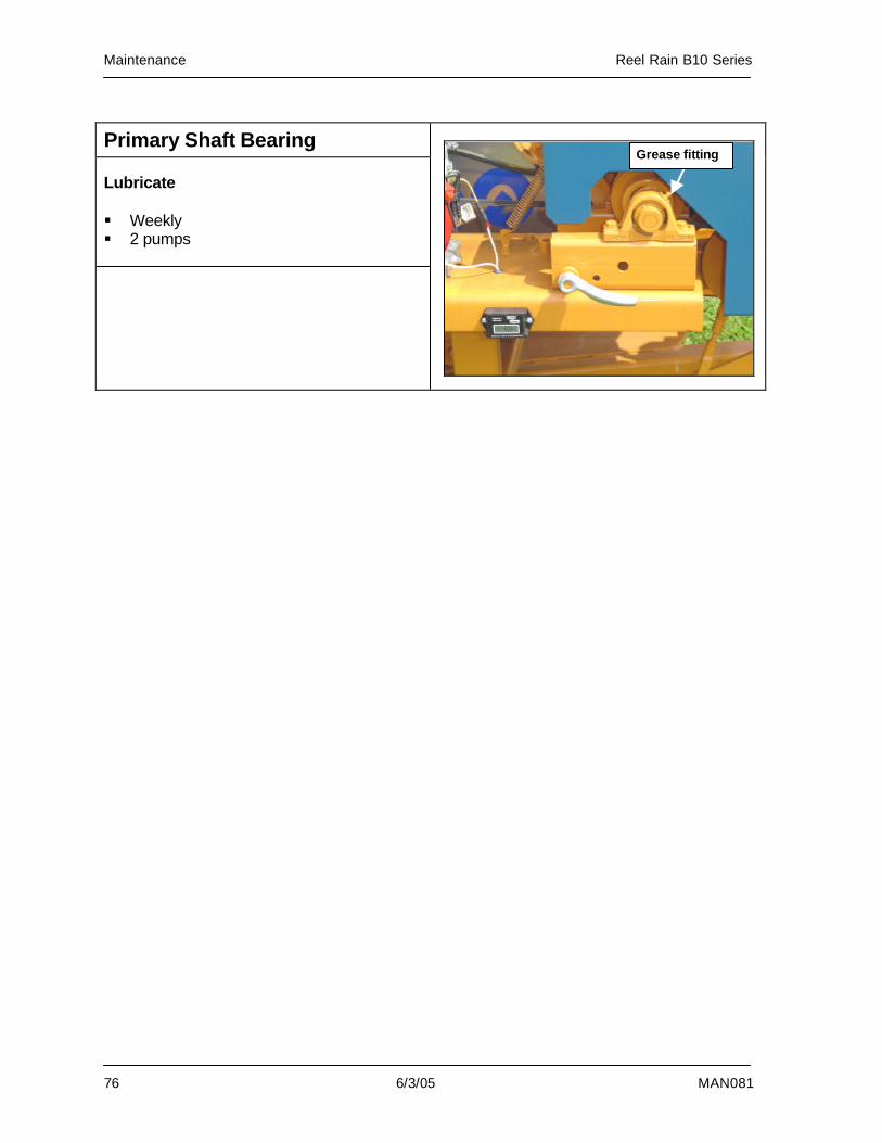
Maintenance Reel Rain B10 Series
76 6/3/05 MAN081
Primary Shaft Bearing Lubricate § Weekly § 2 pumps
Grease fitting
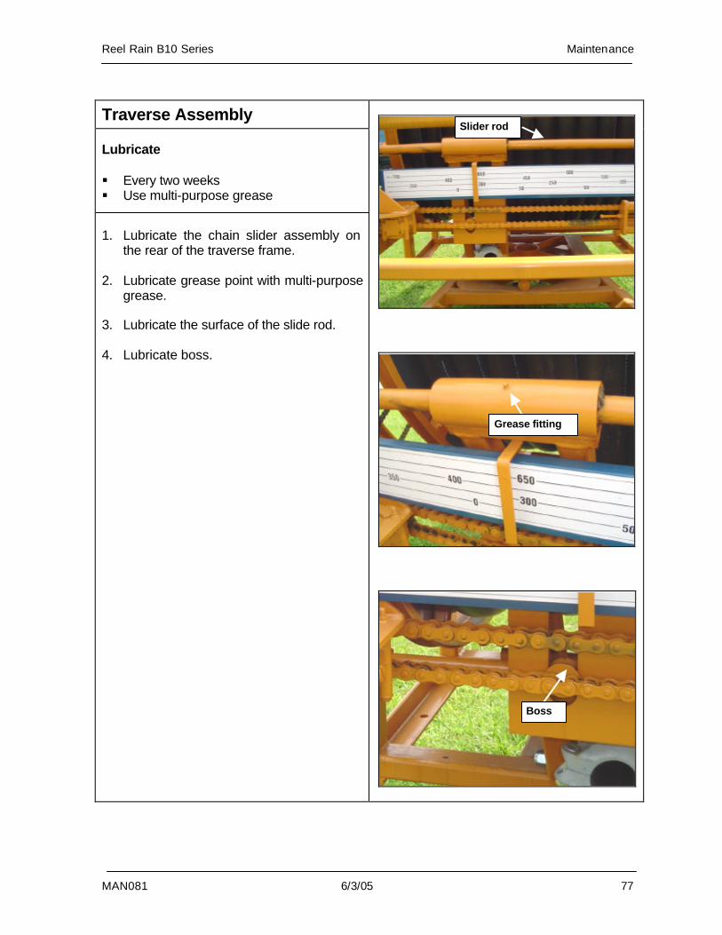
Reel Rain B10 Series Maintenance
MAN081 6/3/05 77
Traverse Assembly Lubricate § Every two weeks § Use multi-purpose grease
1. Lubricate the chain slider assembly on
the rear of the traverse frame. 2. Lubricate grease point with multi-purpose
grease. 3. Lubricate the surface of the slide rod. 4. Lubricate boss.
Slider rod
Grease fitting
Boss
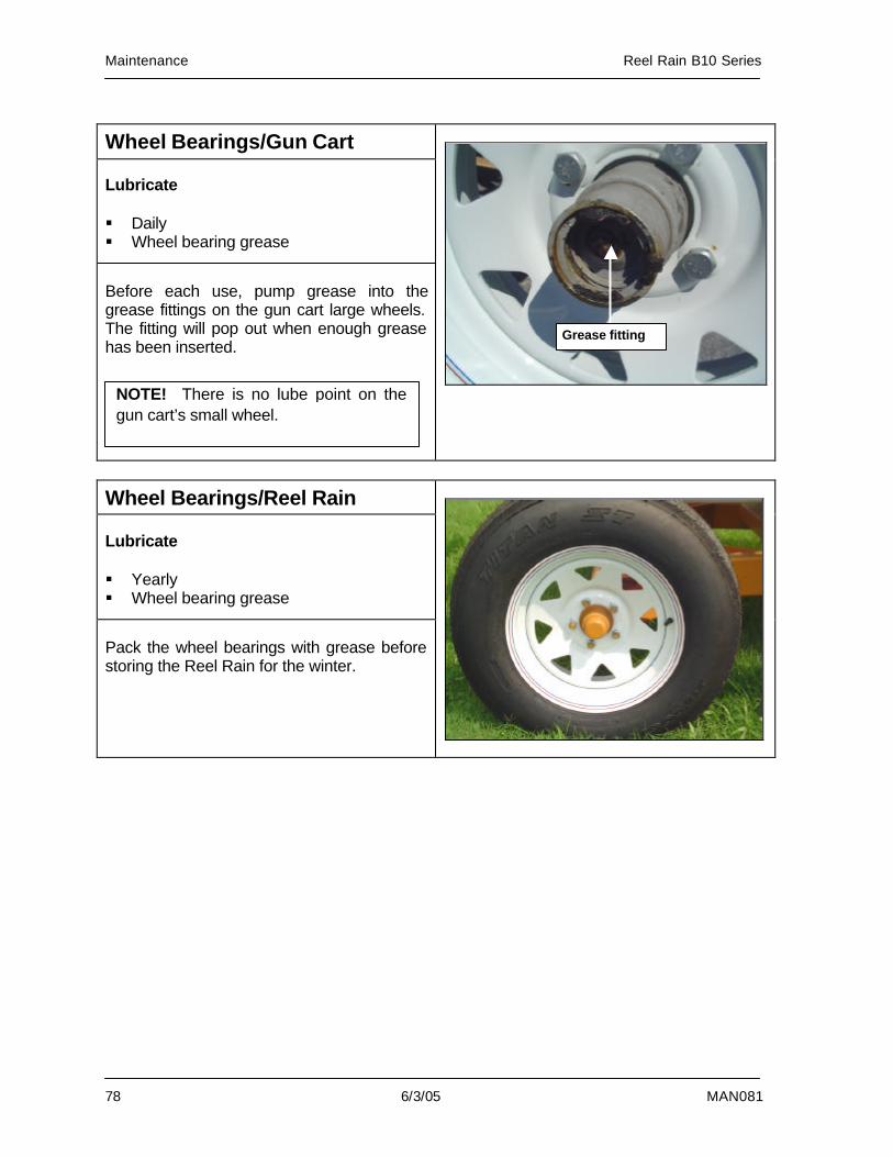
Maintenance Reel Rain B10 Series
78 6/3/05 MAN081
Wheel Bearings/Gun Cart Lubricate § Daily § Wheel bearing grease
Before each use, pump grease into the grease fittings on the gun cart large wheels. The fitting will pop out when enough grease has been inserted.
Wheel Bearings/Reel Rain Lubricate § Yearly § Wheel bearing grease
Pack the wheel bearings with grease before storing the Reel Rain for the winter.
Grease fitting
NOTE! There is no lube point on the gun cart’s small wheel.
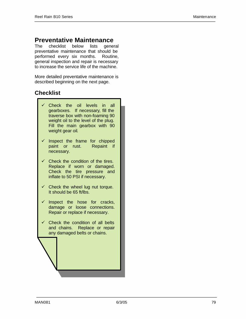
Reel Rain B10 Series Maintenance
MAN081 6/3/05 79
Preventative Maintenance The checklist below lists general preventative maintenance that should be performed every six months. Routine, general inspection and repair is necessary to increase the service life of the machine. More detailed preventative maintenance is described beginning on the next page. Checklist
ü Check the oil levels in all gearboxes. If necessary, fill the traverse box with non-foaming 90 weight oil to the level of the plug. Fill the main gearbox with 90 weight gear oil.
ü Inspect the frame for chipped
paint or rust. Repaint if necessary.
ü Check the condition of the tires.
Replace if worn or damaged. Check the tire pressure and inflate to 50 PSI if necessary.
ü Check the wheel lug nut torque.
It should be 65 ft/lbs. ü Inspect the hose for cracks,
damage or loose connections. Repair or replace if necessary.
ü Check the condition of all belts
and chains. Replace or repair any damaged belts or chains.
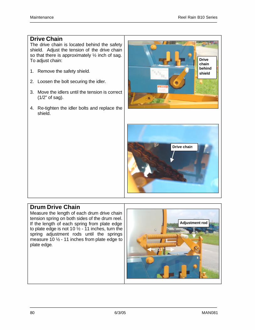
Maintenance Reel Rain B10 Series
80 6/3/05 MAN081
Drive Chain The drive chain is located behind the safety shield. Adjust the tension of the drive chain so that there is approximately ½ inch of sag. To adjust chain: 1. Remove the safety shield. 2. Loosen the bolt securing the idler. 3. Move the idlers until the tension is correct
(1/2” of sag). 4. Re-tighten the idler bolts and replace the
shield.
Drum Drive Chain Measure the length of each drum drive chain tension spring on both sides of the drum reel. If the length of each spring from plate edge to plate edge is not 10 ½ - 11 inches, turn the spring adjustment rods until the springs measure 10 ½ - 11 inches from plate edge to plate edge.
11”
Adjustment rod
Drive chain
Drive chain behind shield
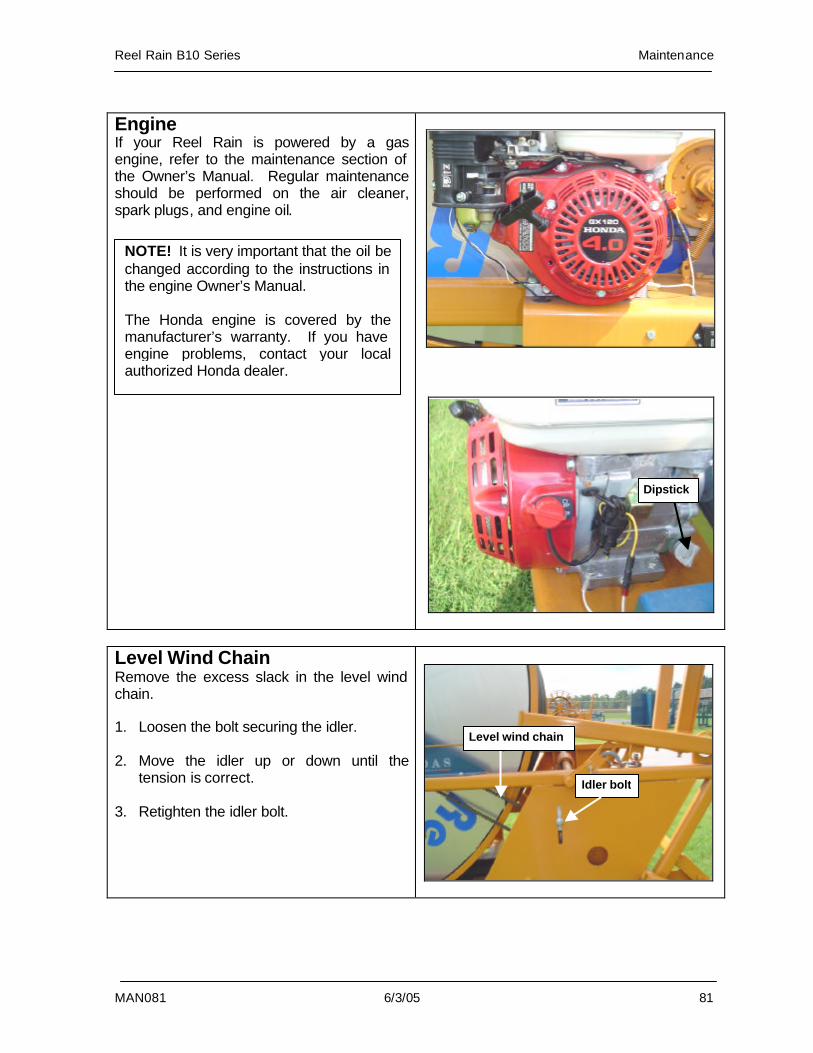
Reel Rain B10 Series Maintenance
MAN081 6/3/05 81
Engine If your Reel Rain is powered by a gas engine, refer to the maintenance section of the Owner’s Manual. Regular maintenance should be performed on the air cleaner, spark plugs, and engine oil.
Level Wind Chain Remove the excess slack in the level wind chain. 1. Loosen the bolt securing the idler. 2. Move the idler up or down until the
tension is correct. 3. Retighten the idler bolt.
Idler bolt
Dipstick
NOTE! It is very important that the oil be changed according to the instructions in the engine Owner’s Manual. The Honda engine is covered by the manufacturer’s warranty. If you have engine problems, contact your local authorized Honda dealer.
Level wind chain
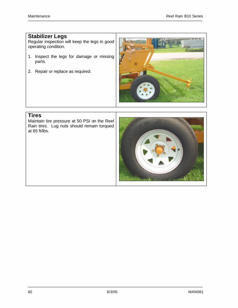
Maintenance Reel Rain B10 Series
82 6/3/05 MAN081
Stabilizer Legs Regular inspection will keep the legs in good operating condition. 1. Inspect the legs for damage or missing
parts. 2. Repair or replace as required.
Tires Maintain tire pressure at 50 PSI on the Reel Rain tires. Lug nuts should remain torqued at 65 ft/lbs.
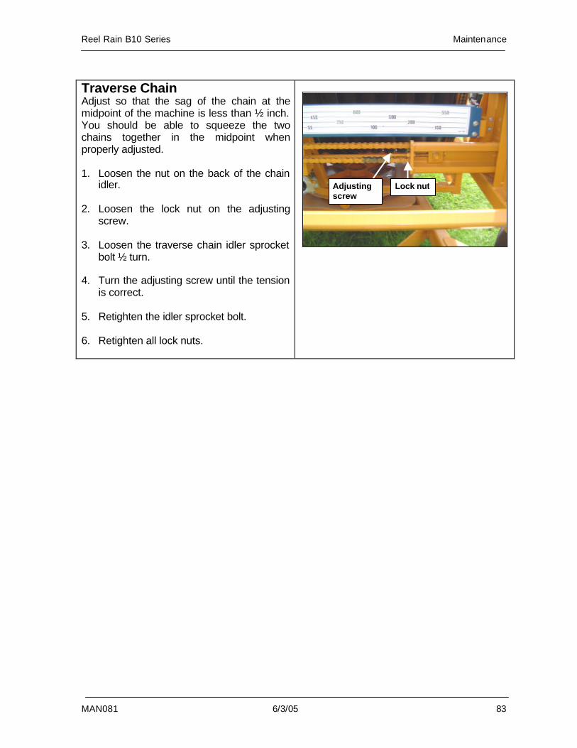
Reel Rain B10 Series Maintenance
MAN081 6/3/05 83
Traverse Chain Adjust so that the sag of the chain at the midpoint of the machine is less than ½ inch. You should be able to squeeze the two chains together in the midpoint when properly adjusted. 1. Loosen the nut on the back of the chain
idler. 2. Loosen the lock nut on the adjusting
screw. 3. Loosen the traverse chain idler sprocket
bolt ½ turn. 4. Turn the adjusting screw until the tension
is correct. 5. Retighten the idler sprocket bolt. 6. Retighten all lock nuts.
Adjusting screw
Lock nut
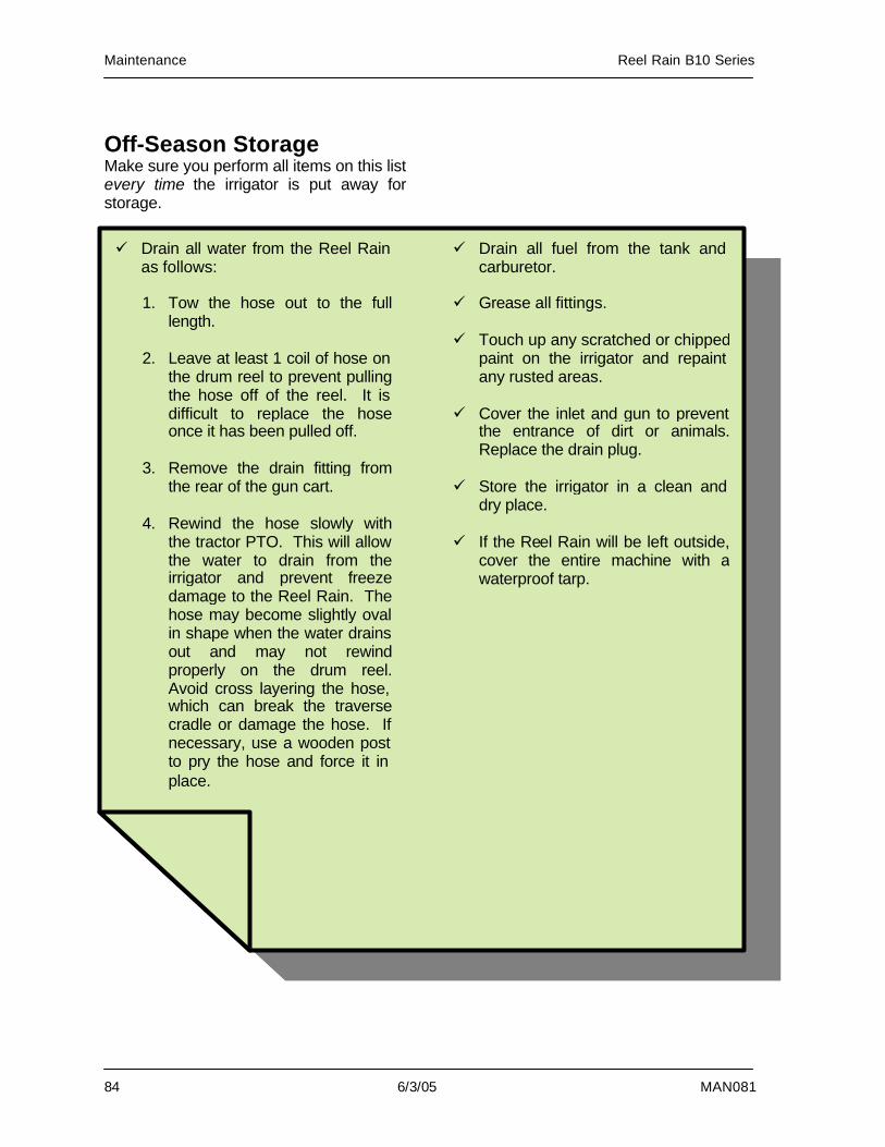
Maintenance Reel Rain B10 Series
84 6/3/05 MAN081
Off-Season Storage Make sure you perform all items on this list every time the irrigator is put away for storage.
ü Drain all water from the Reel Rain as follows:
1. Tow the hose out to the full
length.
2. Leave at least 1 coil of hose on the drum reel to prevent pulling the hose off of the reel. It is difficult to replace the hose once it has been pulled off.
3. Remove the drain fitting from
the rear of the gun cart.
4. Rewind the hose slowly with the tractor PTO. This will allow the water to drain from the irrigator and prevent freeze damage to the Reel Rain. The hose may become slightly oval in shape when the water drains out and may not rewind properly on the drum reel.Avoid cross layering the hose, which can break the traverse cradle or damage the hose. If necessary, use a wooden post to pry the hose and force it in place.
ü Drain all fuel from the tank and carburetor.
ü Grease all fittings. ü Touch up any scratched or chipped
paint on the irrigator and repaint any rusted areas.
ü Cover the inlet and gun to prevent
the entrance of dirt or animals. Replace the drain plug.
ü Store the irrigator in a clean and
dry place. ü If the Reel Rain will be left outside,
cover the entire machine with a waterproof tarp.
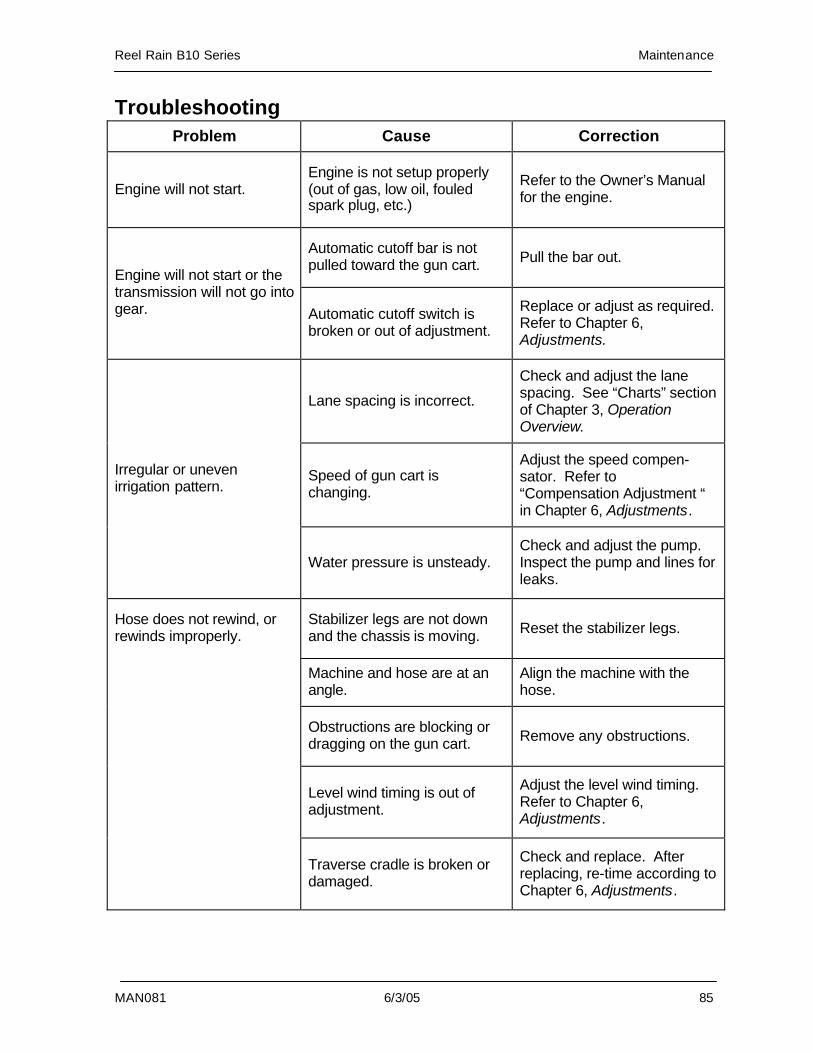
Reel Rain B10 Series Maintenance
MAN081 6/3/05 85
Troubleshooting Problem Cause Correction
Engine will not start. Engine is not setup properly (out of gas, low oil, fouled spark plug, etc.)
Refer to the Owner’s Manual for the engine.
Automatic cutoff bar is not pulled toward the gun cart. Pull the bar out.
Engine will not start or the transmission will not go into gear. Automatic cutoff switch is
broken or out of adjustment.
Replace or adjust as required. Refer to Chapter 6, Adjustments.
Lane spacing is incorrect.
Check and adjust the lane spacing. See “Charts” section of Chapter 3, Operation Overview.
Speed of gun cart is changing.
Adjust the speed compen-sator. Refer to “Compensation Adjustment “ in Chapter 6, Adjustments.
Irregular or uneven irrigation pattern.
Water pressure is unsteady. Check and adjust the pump. Inspect the pump and lines for leaks.
Stabilizer legs are not down and the chassis is moving. Reset the stabilizer legs.
Machine and hose are at an angle.
Align the machine with the hose.
Obstructions are blocking or dragging on the gun cart. Remove any obstructions.
Level wind timing is out of adjustment.
Adjust the level wind timing. Refer to Chapter 6, Adjustments.
Hose does not rewind, or rewinds improperly.
Traverse cradle is broken or damaged.
Check and replace. After replacing, re-time according to Chapter 6, Adjustments.
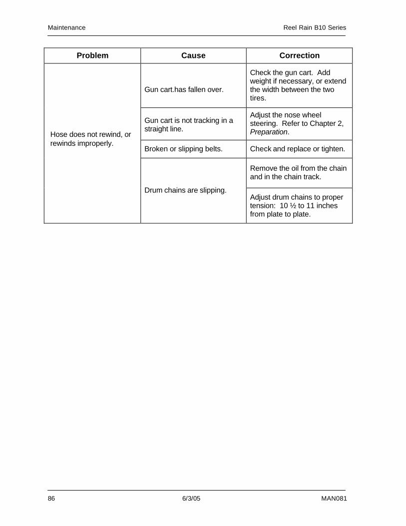
Maintenance Reel Rain B10 Series
86 6/3/05 MAN081
Problem Cause Correction
Gun cart.has fallen over.
Check the gun cart. Add weight if necessary, or extend the width between the two tires.
Gun cart is not tracking in a straight line.
Adjust the nose wheel steering. Refer to Chapter 2, Preparation.
Broken or slipping belts. Check and replace or tighten.
Remove the oil from the chain and in the chain track.
Drum chains are slipping. Adjust drum chains to proper tension: 10 ½ to 11 inches from plate to plate.
Hose does not rewind, or rewinds improperly.