Embed Size (px)
Citation preview

Conference On Railway Excellence Adelaide, 5 – 7 May 2014
REDUCTION OF LOW FREQUENCY LINEAR VIBRATIONS IN LONG HEAVY HAUL CONSISTS
Damian Birkin
B. Eng.
Aurizon
Tim Constable
M.Eng, B. Eng.
Aurizon
Colin Cole
Phd, MEng, BEng
Central Queensland University,
Centre for Railway Engineering
Chris Bosomworth
BSc
Insyte Solutions Pty Ltd
SUMMARY
This paper presents findings from a detailed investigation of in-train forces occurring in Aurizon’s coal haulage operations in the Goonyella region of Central Queensland. The work performed included a significant instrumented wagon based in-train force measurement program, combined with theoretical analysis achieved through computational simulation models.
Aurizon’s coal wagons are operated in tandem pairs, each pair having a drawbar connection between the wagons and auto-coupler connections at the outermost ends. A significant change in recent times has been the introduction of short pack draft gears (polymer/elastomer springs without friction wedges) at the drawbar connections. Conventional draft gears are still used at auto-coupler connections. It was found from the detailed analysis of measured in-train forces that changes have occurred in the system behaviour of contemporary unit train consists as compared to those measured in earlier studies completed in the 1980’s and 1990’s. In particular, durations and occurrences of low frequency linear vibrations, have been significantly reduced in current consists. The paper provides a comparison of measured data and simulated data from older and more recent mathematical models to allow identification of the factors that have changed low frequency vibration behaviour.
The paper provides a valuable update in the understanding of longitudinal dynamics and draft gear modelling.
1.0 INTRODUCTION
In order to optimise operational efficiencies by the introduction of alternate consist designs it is necessary to better understand the behaviour of long heavy haul trains in support of the next phase of coal and commodities markets expansion. This requires a renewed engineering focus on the modelling and management of longitudinal forces in long trains.
Measurements of in-train forces were carried out over an extended period using instrumented wagons in Aurizon’s Central Queensland coal wagon fleet in Central Queensland. The primary objective of this exercise was to analyse the effects of train configurations (length, locomotive positioning), and other factors on in-train forces. This test program also gave the opportunity to evaluate the changes in long train behaviour due to more modern draft gears and drawbar/short pack connections, and to compare and update draft gear modelling. This paper presents insights gained from the field tests and recent
experiments with variations in draft gear modelling.
In particular this paper discusses observable changes in train behaviour due to recent changes in draft gear selection and configuration within Aurizon’s 106 tonne coal wagon fleet. Around 2003 Aurizon implemented a design change to its 106 tonne Central Queensland coal wagons to replace the draft gear at the drawbar end of tandem pair wagons from standard AAR 635mm draft gear pockets utilising a range of commercially available spring, friction wedge draft gear (typically Westinghouse R500, Miner Crown SE and TF880) to 236mm draft gear pockets utilising the Bradken ‘quikdraw ultra-lite’ short pack draft gear. The primary rationale for the change was to enable a tare mass reduction to facilitate improvements in gross to tare load ratio. The change to a more compact draft gear was also viewed as beneficial to reduce free slack at the drawbar connections. In more recent times, Aurizon has also installed Miner TF880Q draft gear at the auto-coupler connections across a significant proportion of its feet. The TF880Q
D. Birkin et al Reduction of Low Frequency Linear Vibrations Aurizon Operations Pty Ltd in Long Heavy Haul Consists
Conference On Railway Excellence Adelaide, 5 – 7 May 2014
is a variant of the Miner TF880 draft gear, with the ‘Q’ offering significantly greater compliance and different friction damping capabilities aimed at reducing the fatigue damaging component of longitudinal in-train forces. This paper discusses some effects of the change in draft gear configuration, in particular that the short pack draft gear appears to have delivered secondary benefits to in-train forces, beyond the immediate benefit to wagon capacity due to tare mass reduction.
2.0 NOTATION
a fwc
m v x Fg
Fr
Ft/db
Vehicle acceleration, m/s2. The non-linear function describing the full characteristics of the wagon connection Vehicle mass, kg. Vehicle velocity, m/s. Vehicle displacement, m. Gravity force components due to track grade, N. Sum of retardation forces rolling resistance, air resistance, curve resistance, air braking,, N. Traction and dynamic brake forces from a locomotive unit, N
3.0 IN-SERVICE TESTING
3.1 Test setup and Background
Aurizon’s Central Queensland coal fleet consists of a large number of tandem 106t wagons. The tandem wagons are semi-permanently coupled with a fixed drawbar and short pack draft gear on each end. On the free ends the standard auto-coupler with TF880Q draft gear is retained. Measuring longitudinal forces using drawbars provide excellent results for the following reasons:
1. Drawbars have a central uniform cross sectional area
2. Vertical loads have little influence on the predominantly longitudinal forces
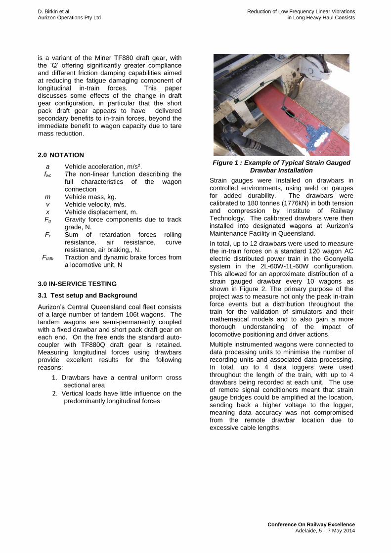
Figure 1 : Example of Typical Strain Gauged
Drawbar Installation
Strain gauges were installed on drawbars in controlled environments, using weld on gauges for added durability. The drawbars were calibrated to 180 tonnes (1776kN) in both tension and compression by Institute of Railway Technology. The calibrated drawbars were then installed into designated wagons at Aurizon’s Maintenance Facility in Queensland.
In total, up to 12 drawbars were used to measure the in-train forces on a standard 120 wagon AC electric distributed power train in the Goonyella system in the 2L-60W-1L-60W configuration. This allowed for an approximate distribution of a strain gauged drawbar every 10 wagons as shown in Figure 2. The primary purpose of the project was to measure not only the peak in-train force events but a distribution throughout the train for the validation of simulators and their mathematical models and to also gain a more thorough understanding of the impact of locomotive positioning and driver actions.
Multiple instrumented wagons were connected to data processing units to minimise the number of recording units and associated data processing. In total, up to 4 data loggers were used throughout the length of the train, with up to 4 drawbars being recorded at each unit. The use of remote signal conditioners meant that strain gauge bridges could be amplified at the location, sending back a higher voltage to the logger, meaning data accuracy was not compromised from the remote drawbar location due to excessive cable lengths.

(1) (11) (23) (31) (43) (53)
1 2 3 4 5 6
(61) (73) (87) (97) (107) (117)
7 8 9 10 11 12
Locomotive
Tandem Wagon Pairs (Wagon No. In Train of Leading Wagon)
# With Instrumented Drawbar
# With Instrumented Drawbar With & DAQ
Wired For Instrumentation
Free {No instrumentation wiring}
Lead Portion of Train
Rear Portion of Train
Figure 2 : Instrumented Wagon Plan and Drawbar Layout
The wagons were fitted with large battery banks and axle driven alternators to keep the systems charged and operational at all times. This allowed continuous data recording throughout the testing period. Drawbar strain gauge data was recorded at 1000Hz, with a 333Hz FIR (finite impulse response) filter, to ensure all forms of behaviour would be recorded. GPS data was also recorded to determine locations of events of interest and also to synchronise other data loggers.
Testing was conducted over several months on the Central Queensland coal network and the train was run in typical traffic as a revenue train. Under these conditions, data for standard train services were able to be recorded.
GPS Data was used to separate the data into individual trips for analysis, with one round trip consisting of a Yard-Mine-Port-Yard. The data was not filtered during processing however any erroneous spikes were removed during post processing.
3.2 Data Analysis
The in-train force data was examined to determine the key influences in the longitudinal load spectrum which Aurizon operates long coal trains. There are essentially 2 categories, peak loads and cyclic loads. Peak loads are critical from a proof load point of view, in that wagons and components are not exposed to loads that exceed the design limits to avoid catastrophic failure. Cyclic loads are perceivably more critical in the railway environment as wagons are designed for long periods of operation (sometimes exceeding 30 years). The load spectrum that they can be exposed to changes over time and needs to be monitored to ensure fatigue cracking does not become a significant issue.
Upon examination of the of in-train forces experienced on Aurizon coal trains, it was clear
that there were several different scenarios for causing high in-train forces and oscillations. The main ones being:
1. Track Elevation/Gradient
2. Train Handling, i.e. Throttle and
Brake Application, including Launch
and Braking
3. Inherent Track Features (Neutral
Sections, etc.)
4. Combination of above features
An example of a typical measured in-train force event is shown in Figure 3. With respect to Figure 3, (and all subsequent graphs in this paper) per standard convention, draft (tensile) forces are shown as positive and buff (compressive) forces as negative. The highest in-train loads are generally experienced when traversing crests and valleys in the track profile. A crest inherently results in a local maximum tensile force when a train is passing over the crest due to basic gravitational forces. In addition to this, a tractional effort is applied by the locomotives as the train climbs the gradient to traverse the crest. The traction force and gravitational force superimpose to further increase the in-train forces. The similar situation occurs when the train traverses downhill gradients and valleys, where the addition of the dynamic brake can add to the compressive forces in the train.

D. Birkin et al Reduction of Low Frequency Linear Vibrations Aurizon Operations Pty Ltd in Long Heavy Haul Consists
Conference On Railway Excellence Adelaide, 5 – 7 May 2014
Figure 3 : High Force Due to Traversing Peak
3.3 Fatigue
Longitudinal forces have been found to be one of the highest driving factors in wagon structure and draw gear component fatigue, due to the size of the loads and also the number of them in one cycle or trip. It is also one of the most controllable loads in the train as it can be manipulated or optimised by adjusting driving methodologies/train configurations etc.
Whilst high forces contribute to wagon fatigue, the low number of large cycles (>1000kN) means that they may not necessarily be the biggest influence. It can actually be the low frequency oscillations that are a higher concern as the high number of cycles can add up fatigue numbers very quickly, also considering that they regularly
result in cycles in the 200-300kN range and in some scenarios result in ranges of up to 800kN.
3.4 Low Frequency Vibrations
Generally the low frequency cyclic vibrations are induced in the train when an abrupt change in the train operation occurs. Predominantly this is in the form of a throttle application or brake application, be it traditional air brakes or dynamic brakes. Generally, a dynamic brake application results in high cyclic forces as the applied braking does not retard the wagons resulting in wagon run-ins and run-outs. The occurrence of low frequency vibrations also depends on the state of the train when the input is applied, predominantly whether it is in compression or tension at the time, speed is also a factor.
An example of a low frequency linear vibration measured from the in-service testing is shown in Figure 4. As evident in Figure 4, the low frequency vibrations occur throughout the train, but are more prominent in the rear 60 wagons. The front 60 wagons have very little in comparison, this is most likely due to the front rake being sandwiched between 2 locomotives, which for the majority of the time are applying the same tractive forces and braking efforts, the trailing 60 wagons however are effectively free to move (within the limits of the couplings) which would allow more movement, and oscillation in a traditional longitudinal vibration mode.
Figure 4 : Example of Longitudinal Vibration after tractive effort is applied
4.0 MODELLING AND SIMULATION
Since before 1989, [1] it has been understood that low frequency longitudinal vibrations can occur in long heavy haul trains in certain conditions. Such vibrations were frequently observed in distributed power trains but could also occur in head end trains. The behaviour that was observed and reported in [1] identified cases where the draft gears, after reaching a
maximum force unload, the wedges do not move or unlock. Measurements on the auto-coupler showed that although the in-train force was cyclic, the draft gears were remaining stationary.
The vibrations only occurred when a single stress state existed throughout the train, for example when the train was stretched over a crest or compressed in a dip. Vibrations in such cases could be initiated by a control change (e.g. change of power notch). The vibrations were
Low frequency vibrations introduced

D. Birkin et al Reduction of Low Frequency Linear Vibrations Aurizon Operations Pty Ltd in Long Heavy Haul Consists
Conference On Railway Excellence Adelaide, 5 – 7 May 2014
characteristically sinusoidal indicating a linear vibratory system. Furthermore damping was small, with vibrations taking as long as 100 seconds to decay. The conclusion was reached that the operating stiffness in these cases was the overall stiffness of the train and as the wedges were locked, the term ‘locked stiffness’ was used. It should be noted that these trains had auto-couplers and wedge clutch type draft gears throughout.
Further testing of distributed power trains was carried out several years later and again low frequency vibrations were confirmed, [2]. Modelling was improved to include the effects of variable friction [3] but the modelling of the ‘locked stiffness’ was the same as in [1]. The wagon connections were still all auto-couplers.
More recently, the testing of the current Aurizon trains has allowed the modelling to be revisited. These new trains were analysed using modelling and simulation analysis is described in the following subsections.
4.1 Train Modelling
A train of 120 wagons with distributed power was modelled in configuration 2L-60W-1L-60W. Each vehicle mass was modelled separately (Figure 5) connected by the non-linear draft gear connection modelling and slack elements (Figure 6). Other forces such as propulsion resistance, curve resistance, grade forces, braking forces, traction forces were added to each vehicle mass as appropriate. Locomotive characteristics of traction and dynamic brakes were applied as forces to locomotive vehicle masses and were modelled from manufacturer’s curves
mn mi m1
fc (xn,xi,vn,vi)
Ft/db
Fr1
Fg1
Fri
Fgi
Fr n
Fgn
fc (xi,x1,vi,v1)
.
.
Figure 5 : Generalised Train Model
Simulation is achieved by numerical solution of the following equations of motion as per [3].
For the lead vehicle:
111/212111 ),,,( grdbtwc FFFxxvvfam (1)
For the ith vehicle:
giridbit
iiiiwciiiiwcii
FFF
xxvvfxxvvfam
/
1111 ),,,(),,,(
(2)
For the nth or last vehicle:
gnrndbntnnnnwcnn FFFxxvvfam /11 ),,,(
(3)
4.2 Wagon Connection Modelling
Wagon connection modelling was completed as in [3], including gap elements for auto-coupler slack, locked stiffness and variable friction wedge modelling, schematic as shown in Figure 6 and 7.
Combined Draft
Gear Model
Limiting Stiffness or
'locked stiffness'
Coupler Slack
Figure 6 : Wagon Connection Model
-2.5
-2
-1.5
-1
-0.5
0
0.5
1
1.5
2
2.5
-0.3 -0.2 -0.1 0 0.1 0.2 0.3
Forc
e, M
N
Inter-Wagon Displacement, m
Figure 7 : Draft Gear Connection Model
Drawbar short pack connections were modelled in the same way, but with reduced auto-coupler slack and an elastomer model replaced the draft gear model. For the short pack there is no ‘locked stiffness’ but the connection stiffness cannot exceed train stiffness and this stiffness acts between loading and unloading curves and at full travel as a ‘limit stiffness’.
The key features of draft gear models, such as shown in Figure 7 are the loading and unloading curve with hysteresis between them resulting in energy loss. The hysteresis arises from the non-linear/elastomer hysteresis and the friction applied by the wedges. The model shown in Figure 7 also shows load rate dependence with stiffer cycles corresponding to slower loading and higher friction values. The steep lines where the load changes direction and falls from the upper

D. Birkin et al Reduction of Low Frequency Linear Vibrations Aurizon Operations Pty Ltd in Long Heavy Haul Consists
Conference On Railway Excellence Adelaide, 5 – 7 May 2014
loading curve to the lower unloading curve are limited in slope by the overall stiffness of the wagon components. In the case of a locking model the wedges remain stationary as load switches from the upper to lower curves. The deflection is via the deflection in other components. Unlocking occurs when the force either exceeds the original upper bound or falls to the unloading line. This behaviour is well documented in [1] and [2].
Variations to the draft gear model shown in Figure 7 were introduced to remove the effect of the ‘locked stiffness’. A surprising result was that the displayed output from the model in the cross plot did not visibly change and this needs some careful explanation. In the case of the original modelling the wedges lock and so the auto-coupler and yoke do not move relative to the wagon. In such a situation the force can fluctuate to a value, even higher than the lock point and as low as the auto-coupler hysteresis unloading curve. If the load reduced below the unloading curve, unlocking usually occurred. In some cases the forces even had to fall below this. Forces of double the force at the original locking point were also observed before unlocking.
If the ‘locking’ behaviour is removed, the initial unloading of the forces is still governed by the ‘limiting stiffness’ ( which is the same magnitude as the locked stiffness). If the forces then increase ( before the unloading curve is reached) this loading rate may be quite slow. As the variable friction in the improved draft gear model [2] [3] delivers very high forces at slow loading rates the behaviour is still very stiff , and could approach the same values as locked stiffness – but with small wedge movement. These different models were tested in train simulation.
4.3 Simulation Results
A simple train simulation was designed with the train stretched over a crest. Locomotive power was first applied to set up draft forces throughout the train. The power was then reduced and re-applied to introduce a disturbance and start longitudinal vibrations. The Simulation is shown in Figure 8.
-20
-10
0
10
20
30
40
0
20
40
60
80
100
120
0 5 10 15
Ele
vati
on
(m
)
No
tch
(%),
Sp
ee
d (
km/h
r)
Track position (km)
Operating Scenario
Loco Throttle-DB %
Speed (km/hr)
Elevation
Track Elevation @ Lead Loco metres
Figure 8 : Train Simulation on Crest
-500
-300
-100
100
300
500
700
900
1100
1300
1500
0 100 200 300 400 500
Co
up
ler
Forc
es
(kN
)
Time (sec)
Coupler Forces
Coupler Forces (kN) (2) Coupler Forces (kN) (12)
Coupler Forces (kN) (25) Coupler Forces (kN) (37)
Coupler Forces (kN) (49) Coupler Forces (kN) (62)
Coupler Forces (kN) (74) Coupler Forces (kN) (86)
Coupler Forces (kN) (98) Coupler Forces (kN) (111)
Coupler Forces (kN) (121)
0
20
40
60
80
100
0 100 200 300 400 500
No
tch
(%),
Ele
vati
on
(m
), S
pe
ed
(km
/hr)
Time (sec)
Operating Scenario
Track Elevation @ Lead Loco metres
Loco Throttle-DB %
Speed (km/hr)
Figure 9 : Train Simulations on Crest – Showing Longitudinal Vibrations – Original
Locking Draft Gear Model
The highest longitudinal vibration forces are located at train position 62, which is directly behind the remote locomotive. The simulation

D. Birkin et al Reduction of Low Frequency Linear Vibrations Aurizon Operations Pty Ltd in Long Heavy Haul Consists
Conference On Railway Excellence Adelaide, 5 – 7 May 2014
was repeated for four different model cases as shown in Figure 10 and 11.
-500
-300
-100
100
300
500
700
900
1100
1300
1500
0 100 200 300 400 500
Co
up
ler
Forc
es
(kN
)
Time (sec)
Coupler Forces
All Connections - Orginal locking model
All Connections - Orginal locking model for TF880Q
Short packs in Drawbar Pairs, Original Locking Model
Figure 10 : Longitudinal Vibrations: Original Locking Model
(Blue –original model, all connections friction draft gears, Red – Softer draft gear (TF880Q),all connections with friction draft gears, Black -– Softer draft gear (TF880Q),and drawbar pairs with short packs.)
-500
-300
-100
100
300
500
700
900
1100
1300
1500
0 100 200 300 400 500
Co
up
ler
Forc
es
(kN
)
Time (sec)
Coupler Forces
All Connections - Orginal locking model
Short packs in Drawbar Pairs, Non Lock draft gear model for TF880Q
Figure 11 : Longitudinal Vibrations: Comparing Original Locking Model with Non-
Locking Model
(Blue –original locking model, all connections friction draft gears, Black – non-locking model, softer draft gear (TF880Q),and drawbar pairs with short packs.)
5.0 COMPARISON OF SIMULATION AND FIELD RESULTS
Measured results were compared with modelling results and better agreement was obtained with the non-lock model. An example of the correlation is shown in Figure 12. From Figure 12, it should be noted that a small time shift is added to the results for clarity so the plots can both be seen. The magnitude of the predicted in-train forces generally follows those measured within ~ 5 – 10% after allowing for the time shift.
Figure 12 : Train position 2, Non locking model with softer draft gear (TF880Q) and drawbar pairs with short packs compared with measured results

D. Birkin et al Reduction of Low Frequency Linear Vibrations Aurizon Operations Pty Ltd in Long Heavy Haul Consists
Conference On Railway Excellence Adelaide, 5 – 7 May 2014
0
200
400
600
800
1000
1200
1400
1560 1610 1660 1710 1760
Co
up
ler
Forc
e (k
N)
Time (sec)
Figure 13 : Zoom in on measured longitudinal vibrations
0
200
400
600
800
1000
1200
1400
1600 1650 1700 1750 1800
Co
up
ler
Forc
e (k
N)
Time (Sec)
Figure 14 : Zoom in on simulated longitudinal vibrations – with a non-lock model
6.0 DISCUSSION
The data from the field test programs as shown in Figure 7 and 8 reconfirms the basic understanding of longitudinal train dynamics showing the effects of in-train position and grade (Figure 7) and low frequency longitudinal vibrations ( Figure 8). In Figure 8, the lower plot shows quite sinusoidal force behaviour, indicating linear behaviour. The frequency can be observed as 0.08 Hz which is very similar to the typical 0.1Hz published much earlier in [1] and [2]. While similar, it does indicate a ‘softer’ train coupling system than these earlier systems which consisted only of friction type draft gears.
In the process of comparing this new field data with simulation, it was found that the simulation data had larger magnitude and longer durations of low frequency vibration than the field data. The modelling of the wagon connections was then revisited with the results presented in Figures 9, 10 and 11. There were two variations on the original modelling (a) the addition of short pack draft gears at drawbar connections (no friction elements), and, (b) the removal of the ‘wedge locking’ feature from the modelling. The later was completed because it was though that the original conditions in which wedge locking was observed in [1] and [2] did no longer exist.
The presence of the short packs would ensure that draft gear movements would continue and these movements would probably also unlock the conventional draft gears in each wagon pair. The revised modelling was developed and tuned to match operating data. An example of this is given in Figure 12.
The modelling was then interrogated using a hypothetical example of a train operating on a simple crest (scenario shown in Figure 8) with controls as in Figure 9. The results are very ‘clean’ as they lack other disturbances from normal track topography features and illustrate the effects of these changes. The forces shown in Figure 9 show the responses from the original modelling with no short pack draft gears and locking wedges.
The results are characteristically linear with the largest force oscillations in the centre of the train. The mode is basically that of a ‘piano accordion’. The train is stretching and contracting, (note that the large displacements will be at the train ends). A comparison was then made between the original modelling (representative of RF-361 draft gears) and the same modelling with stiffness’s modified to match the new TF-880 Q (Figure 10).
The differences are quite small, the force peaks from the TF-880-Q are very slightly reduced and the frequencies of vibration are the same. Also in Figure 10 the original locking modelling is combined with short pack modelling and significant improvement in the damping is observed. In all cases the low vibration frequency was observed to be the same. This would be expected as the behaviour is largely governed by the overall wagon stiffness. The vibration frequency was 0.1Hz.
Further comparison of the new TF-880-Q modelling was completed in Figure 11 with the non-locking case. It is somewhat surprising that this significant change did not result in any visible difference in the results. A possible explanation is as follows. In both the locking and non-locking models the behaviour of the draft gears is governed by the 'locked' or 'limit stiffness' of the system. While the auto-coupler forces are switching from loading to unloading, wedges are stationary. The only difference in the behaviour is when the loading state returns to regions above the drop hammer hysteretic zone.
In the case of a locked model, the force characteristic returns along the same path that it unloaded on and may even exceed the earlier peak. As loading is slow, it does not unlock. In earlier tests, this could carry on for up to 100 seconds and would usually unlock by falling lower than the unloading curve. Forces could be observed of up to double that of the force where the original ‘locking’ occurred. It will be noted

D. Birkin et al Reduction of Low Frequency Linear Vibrations Aurizon Operations Pty Ltd in Long Heavy Haul Consists
Conference On Railway Excellence Adelaide, 5 – 7 May 2014
that this is occurring on Figure 9, initial locking at ~900kN, vibrations built to ~1350kN.
When the ‘locking feature’ is removed, the forces are governed by the variable states of friction in the wedge system. At very low velocity, these can deliver ‘pseudo stiffness’s greater than the ‘locked’ or limit stiffness. If this occurs no change will be seen. It therefore may be possible to simplify the model by Cole in [2] and [3] to include just the variable loading rate friction wedge model and limit stiffness. There is however no change to the Duncan and Web model in [1] as without the ‘locked stiffness’ modelling the low frequency vibrations will not be simulated. As the variable loading rate friction wedge model [2] and [3] seems to automatically incorporate the ‘locking behaviour’ it can probably be concluded that it is closer to an explicit model (white box model) more directly representing the physics of the draft gear components. Arguments and discussions and improvements will no doubt be ongoing.
Testing this idea further a comparison is made between the measured data and the simulated data using field conditions as inputs, (real track etc), Figures 13 and 114. While the correspondence is quite good and noting that there are many sources of error in such comparisons, the damping in the simulated data appears to be greater and the responses less sinusoidal, (Figure 14). This result suggests more support for the original locking modelling, which is a stick-slip rather than a variable velocity friction model. At this point it should be realised that more data will be needed to be sure of the more accurate choice of model, and it likely that it will be a probability based answer rather than a clear recommendation. Coulomb friction conditions in the wedges (i.e. wear, surface conditions, lubricant materials and contamination) will always add uncertainties to expected results.
The most important result from both the field testing and the modelling investigation is that short draft packs without friction wedges ( so no locking) have had the effect of increasing damping and reducing low frequency longitudinal vibrations.
In practical terms the benefits of the change in behaviour can be summarised as follows. Referring to Figure 11, it can be noted that with the original draft gear set-up the oscillations in-train forces reach a highpoint around the 200 second mark. At this point in time, the linear vibration behaviour has several influences on the loading imposed on the wagons. Firstly when superimposed onto the inherent mean in-train force, original draft gear setup results in an increase in the maximum draft force by around
30% of the mean load at this point, compared to just 10% for the improved short pack scenario.
The other effect of the new configuration which has significant engineering benefits is the reduction of the cyclic loads imposed by the linear vibration behaviour. At the highpoint, the cyclic load range imposed by the previous draft gear set-up is over six (6) times greater than that achieved with the short pack configuration. Assessments of the two scenarios indicate the reduced low frequency linear vibration behaviour results in a reduction of approximately 70% of the fatigue damage (generally proportional to the cubic of the load range).
7.0 CONCLUSION
The field testing and simulation of the Aurizon coal trains has provided a valuable update to the understanding of longitudinal train dynamics for modern draft gear systems.
The addition of short draft packs at drawbar connections has significantly improved damping in the situations of low frequency vibrations and could have positive effects on fatigue life.
Simulation and modelling of wagon connections revisited the understanding of ‘locked stiffness’ and it is possible that the behaviour might be represented equally well by modelling variable friction modelling and a limit stiffness.
Confirmation of the exact mechanisms for the significant reduction in linear vibration behaviour could be considered by further investigation and research into the phenomenon.
REFERENCES
[1] Duncan I.B and Webb P.A, The longitudinal Behaviour of Heavy Haul Trains Using Remote Locomotives, 4th International Heavy Haul Conference, Brisbane (1989), pp 587-590
[2] Cole C, Improvements to Wagon Connection Modelling for Longitudinal Train Simulation. Conference on Railway Engineering, Rockhampton (1998), pp 187
–194, Institution of Engineers, Australia.
[3] Cole C, Chapter 9 Longitudinal Train Dynamics, in Handbook of railway vehicle dynamics, Ed. Iwnicki S, Taylor and Francis, London, pp 239-278., 2006.