Embed Size (px)
Citation preview
HYDRAULICS BRANCH OFFICIAL FILE COPY
F MERIENCE WITH FLOW INDUCED VIBRATIONS
HENRY T. FALVEY r
PAP - 386
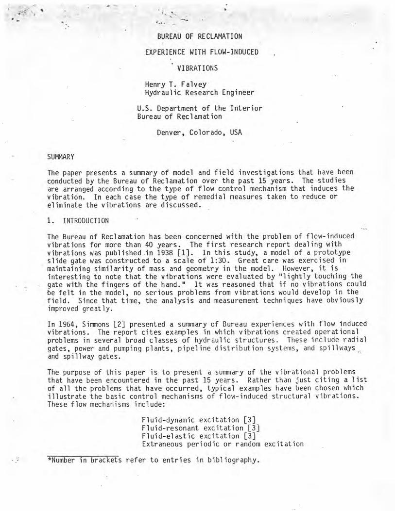
BUREAU OF RECLAMATION
EXPERIENCE WITH FLOW-INDUCED
VIBRATIONS
Henry T. Falvey Hydraulic Research Engineer
U.S. Department of the Interior Bureau of Reclamation
Denver, Colorado, USA
SUMMARY
The paper presents a summary of model and field investigations that have been conducted by the Bureau of Reclamation over the past 15 years. The studies are arranged according to the type of flow control mechanism that induces the vibration. In each case the type of remedial measures taken to reduce or eliminate the vibrations are discussed.
1. INTRODUCTION
The Bureau of Reclamation has been concerned with the problem of flow-induced vibrations for more than 40 years. The first research report dealing with vibrations was published .in 1938 [1]. In this study, a model of a prototype slide gate was constructed to a scale of 1:30. Great care was exercised in maintaining similarity of mass and geometry in the model. However, it is interesting to note that the vibrations were evaluated by "lightly touching the gate with the fingers of the hand." It was reasoned that if no vibrations could be felt in the model, no serious problems from vibrations would develop in the field. Since that time, the analysis and measurement techniques have obviously improved greatly.
In 1964, Simmons [2] presented a summary of Bureau experiences with flow induced vibrations. The report cites examples in which vibrations created operational problems in several broad classes of hydraulic structures. These include radial gates, power and pumping plants, pipeline distribution systems, and spillways', and spillway gates.
The purpose of this paper is to present a summary of the vibrational problems that have been encountered in the past 15 years. Rather than just citing a list of all the problems that have occurred, typical examples have been chosen which illustrate the basic control mechanisms of flow-induced structural vibrations. These flow mechanisms include:
Fluid-dynamic excitation [3] Fluid-resonant excitation [3] Fluid-elastic excitation [3] Extraneous periodic or random excitation
*Number in brackets refer to entries in bibliography.
2. FLUtb-DYNAMIC EXCITATION y,
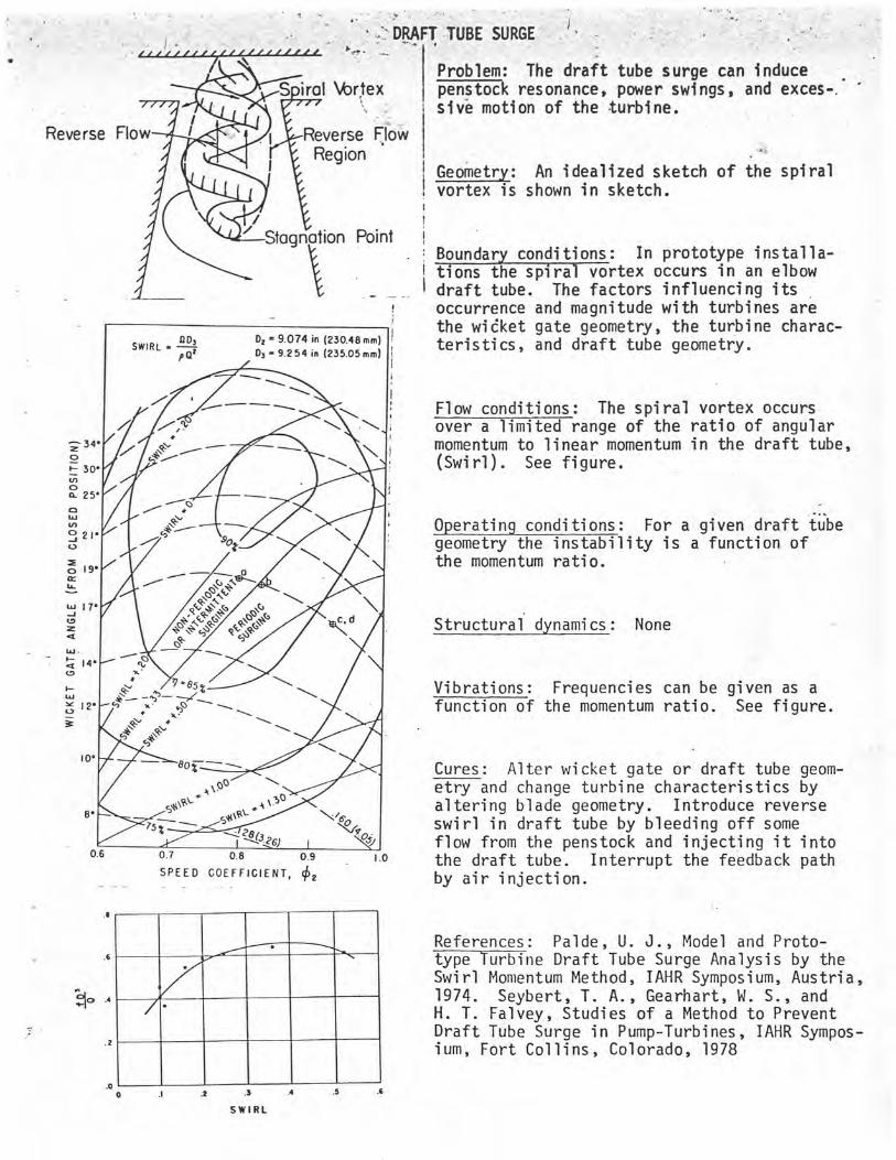
This type of vibration is characterized by two critical locations in the flow. One location is sensitive to disturbances and the other location is a site where new disturbances are self-generating. The new disturbances feed back through the fluid and affect the sensitive location. This type of mechanism can be observed with swirling flow in a tube, chart A. With sufficient angular-momen-tum a reverse flow region forms. A single processing spiral-shaped vortex commonly forms at the boundary of the reverse flow region. The sensitive site is located where the vortex attaches to the upper flow boundary. The site of new disturbances -is located at the stagnation point and the feedback path is formed by the reverse flow. When appropriate, these locations will be identi-fied in the examples which are discussed below.
Three examples of the fluid-dynamic feedback have been studied by the Bureau. These are the draft tube surge, overflow nappe, and spillway-outlet junctions.
The draft tube surge has been found to be a function of the ratio of the angular to linear momentum of the flow entering the draft tube [4]. For a typical turbine, constant values of this ratio, called swirl, define the surging range of the unit, Chart A. All reaction turbines exhibit surging characteris-tics. The three most significant parameters affecting the swirl are the wicket gate geometry, the runner performance characteristics, and the draft tube geometry. Corrective measures to reduce the surging have included changing the runner characteristics; stabilizing the point of new disturbances by cones rising from the draft tube floor; eliminating the feedback path by filling the reverse flow region with air, water vapor, or solid cores; dissipating the angular momentum with fins on the draft tube walls; introducing counter rotating swirl [5]; and changing the. draft tube shape.
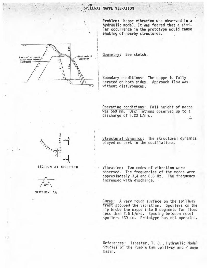
The vibration problems of overflow nappes at small discharges are well known. Therefore, the Bureau investigates this type of-vibration in every new hydraulic structure that contains an overflow nappe [6], chart B. For these vibrations,
_ the sensitive site is located where the nappe leaves the structure. The site of the new disturbances is located where the nappe strikes the downstream pool. The disturbances are fed back through the air column beneath the nappe. Experiments have shown that the vibrations can be eliminated by disrupting the feedback path. One method of accomplishing this is to break the nappe into short segments through the use of spoilers.
The fall height of the nappe in the model was 560 mm. With this fall height, oscillations were observed with a discharge up to 1.23 (liters/s) per meter width of crest. Two modes of vibration were observed. The frequencies of these modes were approximately .3.4 and 6.6 Hz. The frequency was found to increase with discharge. The vibration was stopped by the addition of spoilers to the lip of the spillway. The spacing between the spoilers was 430 mm in the model. This solution has not been verified as water has never passed over the prototype spillway. A curious phenomenon was noted in the model. Quite accidently the model spillway surface was roughened by an overspray of paint droplets. This additional roughness apparently acted upon the location which is sensitive to disturbances and stopped the vibration.
2
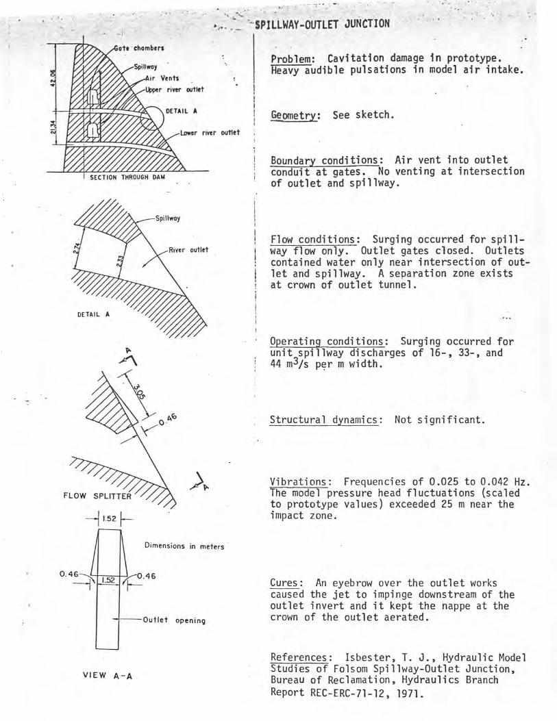
Hydraulic model studies of Spillway flow assingg over a nonoperatiny outlet portal revealed an unsuspected flow vibration [7], chart C. The intersection between the crown of the outlet portal and the spillway face was the location of the sensitive site. When the.pressure at this location is low, the spillway jet is deflected somewhat into the outlet portal. The point where it impacts is the source of the new disturbances.!. Water from the deflected spillway jet gradually fills the outlet conduit causing pressures at the sensitive site to increase. When the pressures at the sensitive site become sufficiently large, the spillway jet is deflected out of the outlet portal and the water in the outlet conduit quickly drains. This process decreases the pressure at the sensitive point and the cycle repeats. It may just be coincidental, but the largest pressure fluctuations in the structure coincided with the most heavily damaged areas in the prototype. The frequency of the oscillations was in the range of 1.5 to 2.5 cycles per minute (prototype). During the surging, heavy audible pulsations were noted in the model air vent. The solution of this problem was to eliminate the site of new disturbances by adding an eyebrow over the outlet. The effect of the eyebrows is to always keep the impact point of the spillway jet downstream of the outlet. The eyebrows also provided aeration to the sensitive area at all times thus preventing the formation of low pressures.
3. FLUID-RESONANCE EXCITATION
This type of vibration is identical with the fluid-dynamic feedback except that a resonant element is placed in the feedback path.
The Bureau experience with this type of vibration has been limited to open channel flow problems. One typical example is at bridge piers in canals.
The occurrence of waves traveling upstream of bridge piers in canals has been studied both in the field and in the laboratory [8]. In this case, the bridge pier consisted of five identical rectangular piles separated by short spacings, chart D. It has been shown that the cause of these waves is the alternate vortex shedding at the trailing end of the pier or pier elements [9]. If the shedding frequency matches the resonant frequency of the space between the row of piers and the canal bank, then large amplitude waves can be formed. In the case of rectangular cross sections, the resonant frequency can be predicted analytically. However, with trapezoidal sections, model studies must be used to predict the resonant conditions.
In the field, crest to trough amplitudes of about 600 mm were observed. The frequency of the waves was about 0.4 Hz for a mean flow velocity of 1.1 m/s and a flow depth of 4.8 m. The distance between wave crests was between 7.5 and 10.5 m. In addition to the waves, a beat frequency of about 0.07 Hz was observed in the wave trains.
The problem was cured by filling the spaces between the piers. The effect of this modification is to eliminate all but the most downstream source of disturbances at the pier.
4. FLUID-ELASTIC EXCITATION
This type of vibration is identical with the fluid-dynamic feedback except that the elastic properties of the structure influence the excitation. Two examples of this type of vibration are fixed cone valves and trashrack bars. Since the
Kl
problem of trashrack vibrations' -has Just begun in the Bureau, only the vibra- tions of hollow cone valves-,will be discussed.
A fixed cone - valve is a flow-regulating device which consists of a cone supported by a'series of vanes. Closure of the valve is accomplished by a sleeve which passes over both the vanes and the fixed cone. The vanes and the the fixed cone represent a spring-mass system within the flow which can react with fluctuations within the flow. This reaction causes new disturbances which then interact with the valve and the entire fluid-elastic system locks on to a specific frequency. Hydraulic model studies were made of two fixed cone valves discharging into a long circular tunnel [10], Chart E. In the model studies all geometric sclaes were similar, but no effort was made to scale the elasticity of the valve. Pressure traces taken in the valve chamber did not reveal any significant periodic disturbances.
Subsequent field tests indicated a very large pressure fluctuation occurred with a frequency of about 85 Hz, chart E. This frequency coincided very closely with that which can be predicted from the elastic vibration of the fixed cone in a torsional mode [11]. It is reasonable to expect that the vibration of the valve caused discharge fluctuations from the valve. These manifested themselves as pressure fluctuations in the valve chamber. The only solution to this problem would be a redesign of the valve to change its elastic properties. In this particular field installation severe vibrations of the operating mechanism were observed for valve openings exceeding 80 percent. Therefore, the valve travel was limited to this value.
5. EXTRANEOUS PERIODIC OR RANDOM EXCITATION
In this type of vibration, the affected structure is separate from the source of the excitation and neither contributes to nor attenuates the source. An example of periodic excitation is penstock resonance. Two examples of random excitation are center walls in hollow jet valve stilling basins and butterfly valves located downstream of a Y-branch.
The Fremont Canyon Powerplant in Wyoming consists of two units located at the end of a very long power conduit, chart F. Each unit could cause severe pres-sure fluctuations to occur in its respective penstock when operated at gate openings greater than 78 percent. This is normally a smooth operating range for a reaction turbine. However, field measurements eventually showed that the exit area of the turbines was about 14 percent too small for this particular instal-lation. The original units exhibited draft tube surges with frequencies ranging between approximately 1.0 and 1.9 Hz.
When the draft tube surge frequency was between 1.4 and 1.9 Hz, the penstocks would resonate. The amplitude of the penstock pressure fluctuations was 16.9 m with a mean pressure head of 84.4 m.
A large number of remedies were tried to eliminate the resonance before it was discovered that the discharge area of the runner was too small. None of these remedies were successful. The cure for this problem was to trim the trailing edges fo the turbine blades, chart F. This essentially changed the runner characteristics so that it ran smoothly above 95 percent gate. Resonance still occurs for gate openings between 85 and 95 percent. However, this plant is operated in such a fashion that it can rapidly pass through this rough zone.
4
Hydraulic model studies were made of a hollow-jet valve stilling basin following extensive damage to the center wall [12], chart G. This basin contains two hollow-jet valves that discharge into a common structure. Since the valves may operate either singly or together, their respective flows were kept separate in the basin by a center wall. The annular flow from each valve is transformed into a solid jet before entering the stilling basin by wedges located on the walls just downstream of the valves. The wedges create separation zones-on each side of the basin. Vertically oriented air-entraining vortices form within the separation zones. These vortices coupled with the horizontally oriented vortices in the hydraulic jump, which forms in the basin, create a very turbulent three-dimensional flow pattern. The spectrum of this turbulence can be characterized as being narrow-band low-frequency. noise [13]. Fatigue cracks have been found at the bottom of the center walls of several basins. The natural frequency of the wall lies within the narrow-band turbulent pressure fluctuation spectrum. The solution at Navajo Dam was to eliminate both the center wall and the wedges. This solution eliminated the damage but now symmetrical operation of both valves is required.
The final example of extraneous control deals with the vibration of a butterfly valve located downstream from a Y-branch [14], chart H. The butterfly valve vibrated with a period of 2 to 3 seconds at a discharge of 165 m3/s and a head of 37 m at the Y-branch. In addition, the valve tended to vibrate toward a closed position at these flow conditions. Laboratory studies showed that the source of the problem was nearly random excitation of the valve. The random excitations were created by separation of the flow in the Y-branch. The problem was eliminated by streamlining the Y-branch through the addition of filler blocks.
6. CONCLUSIONS
In all of these examples of flow-induced vibrations, it has been possible to identify the type of excitation which controlled the vibration. Identification of the excitation mechanism makes it possible to identify possible remedial actions that can be taken to eliminate or reduce the magnitude of the problem.
7. REFERENCES
[1] Streeter, V. L., Progress Report on Parker Dam Gate Tests, Vibration Studies, Parker Dam Project, Bureau of Reclamation, Hydraulics Branch Report HYD-38, 1938
[2] Simmons, W. P., Experiences of the Bureau of Reclamation with Flow-induced Vibrations in Hydraulic Structures, Bureau of Reclamation, Hydraulics Branch Report HYD-538, 1964
[3] Rockwell, D., and Naudascher, E., Review - Self-Sustaining Oscillations of Flow Past Cavities, Transactions of the American Society of Mechanical Engineers, Journal of Fluids Engineering, Vol. 100, pp. 152-165, 1978
[4] Falvey, H. T., and Cassidy, J. J., Frequency and Amplitude of Pressure Surges Generated by Swirling Flow, International Association for Hydraulic Research, Hydraulic Machinery Symposium, Stockholm, Sweden, 1970
[5] Seybert, T. A., Gearhart, W. S., and Falvey, H. T., Studies of a Method to Prevent Draft Tube Surge in Pump-Turbines, IAHR Hydraulic Machinery Symposium, Fort Collins, Colorado, 1978
5
[6] Isbester, T. J., Hydraulic Model Studies of the Pueblo Dam Spillway and Plunge Basin, Bureau of Reclamation, Hydraulic Branch Report REC-ERC-71-18, 1971
[7] Isbester, T.J., Hydraulic Model Studies of Folsom Spillway-Outlet Junction,.Bureau of Reclamation, Hydraulics Branch Report REC-ERC-71-12, 1971
[8] Schuster, J. C., Canal Capacity Studies Wave Formation by Bridge Piers, Bureau of Reclamation, Hydraulics Branch Report HYD-485, 1967
[9] Toebes, G. H., Flow-induced Structural Vibrations, Journal of the Engineer-ing Mechanics Division, American Society of Civil Engineers, Vol. 91, December 1965, pp. 39-66
[10] Beichley, G.-L., Hydraulic Model Studies of Portage Mountain Development Low-level Outlet Works, British Columbia, Canada, Bureau of Reclamation, Hydraulics Branch Report HYD-562, 1966
[11] Mercer, A. G., Vane Failures of Hollow-Cone Valves, International Associa-tion for Hydraulic research, Hydraulic Machinery Symposium, Stockholm, Sweden, 1970
[12] King, D. L., Hydraulic Model Studies of the Modified Outlet Works Stilling Basin, Navajo 'Dam, Colorado River Storage Project, New Mexico, Bureau of Reclamation, Hydraulics Branch Report HYD-573, 1967
[13] Falvey, H. T., and King, D. L., Spectral Analysis, A Prototype Study, Paper presented at the Annual Hydraulics Division Conference, American Society of Civil Engineers, Logan, Utah, August 20-22, 1969
[14] Ball, J. W., Calibration of Hollow-jet Valves and Vibration Studies of Outlet Works Y-branch, Falcon Dam, Bureau of Reclamation, Hydraulics Branch Report HYD-474, 1960
Z 34 0
30' N O a 25' 0 W N U 21'
0 19'
W 17' J Z a
_ W
Z 14• O
W U 12•
3
0
d
x'
?v ~-85Z \
r I
Reverse FIi
DRAFT TUBE SURGE
Problem: The draft tube surge can induce . lortex penstock resonance, power swings, and exces-.
sive motion of the turbine.
rse Flow Lion
Geometry: An idealized sketch of the spiral vortex is shown in sketch.
I
i Point ! Boundary conditions: In prototype installa- bons the spiral vortex occurs in an elbow draft tube. The factors influencing its .
I occurrence and magnitude with turbines are
SWIRL - IID, D2 - 9.074 in (230.48 mm)
oat D3 - 9.254 in (235.05 mm)
the wicket gate geometry, the turbine charac-teristics, and draft tube geometry.
Flow conditions: The spiral vortex occurs over a limited range of the ratio of angular momentum to linear momentum in the draft tube, (Swirl). See figure.
Operating conditions: For a given draft tube geometry the instability is a function of the momentum ratio.
Structural dynamics: None
Vibrations: Frequencies can be given as a function of the momentum ratio. See figure.
80 7
cavo—
z z\3 4)
U./ 0.8 0.9 1.0
SPEED COEFFICIENT, ~2
Cures: Alter wicket gate or draft tube geom-etry and change turbine characteristics by altering blade geometry. Introduce reverse swirl in draft tube by bleeding off some flow from the penstock and injecting it into the draft tube. Interrupt the feedback path by air injection.
References: Palde, U. J., Model and Proto-type Turbine Draft Tube Surge Analysis by the Swirl Momentum Method, IAHR Symposium, Austria, 1974. Seybert, T. A., Gearhart, W. S., and H. T. Falvey, Studies of a Method to Prevent Draft Tube Surge in Pump-Turbines, IAHR Sympos-ium, Fort Collins, Colorado, 1978
.o 0 .7 .. .S .6
SWIRL
• SPILLWAY NAPPE VIBRATION
Limits of air volume under nappe buttresses
/
/ i i
/ /
Problem: Nappe vibration was observed in a ydrauTic model. It was feared that a simi- lar occurrence in the prototype would cause shaking of nearby structures.
I •
i
-first made of Geometry: See sketch. oscillation
1
I
Boundary conditions: The nappe is fully aerated on both sides. Approach flow was
Iwithout disturbances.
Operating conditions: Fall height of nappe was 560 mm. Oscillations observed up to a discharge of 1.23 L/m•s.
E E
A Structural dynamics: The structural dynamics
I~I 1 played no part in the oscillations.
J A
SECTION AT SPUTTER Vibration: Two modes of vibration were observed. The frequencies of the modes were approximately 3,4 and 6.6 Hz. The frequency increased with discharge.
50" ~\
SECTION AA
Cures: A very rough surface on the spillway crest stopped the vibration. Spoilers on the lip broke the nappe into 8 segments for flows less than 2.5 L/m•s. Spacing between model spoilers 430 mm. Prototype has not operated.
References: Isbester, T. J., Hydraulic Model Studies of the Pueblo Dam Spillway and Plunge Basin.
0.4
Dimensions in meters
46
Outlet opening
F
-- 1.52 [-
►,:. ~~ 'SPILLWAY-OUTLET JUNCTION
I SECTION THROUGH DAM
Problem: Cavitation damage in prototype. Heavy audible pulsations in model air intake.
Geometry: See sketch.
i
Boundary conditions: Air vent into outlet conduit at gates. No venting at intersection of outlet and spillway.
ate chambers
Spillway
it Vents
-.-UDDer river outlet
DETAIL A
Lower river outlet
Flow conditions: Surging occurred for spill- way flow only. Outlet gates closed. Outlets
i contained water only near intersection of out- let and spillway. A separation zone exists at crown of outlet tunnel.
i i
Operating conditions: Surging occurred for unit spillway discharges of 16-, 33-, and 44 m3/s per m width.
Structural dynamics: Not significant.
Vibrations: Frequencies of 0.025 to 0.042 Hz. The model pressure head fluctuations (scaled to prototype values) exceeded 25 m near the impact zone.
Cures: An eyebrow over the outlet works caused the jet to impinge downstream of the outlet invert and it kept the nappe at the crown of the outlet aerated.
References: Isbester, T. J., Hydraulic Model Studies of Folsom Spillway-Outlet Junction,
VIEW a-a Bureau of Reclamation, Hydraulics Branch Report REC-ERC-71-12, 1971.
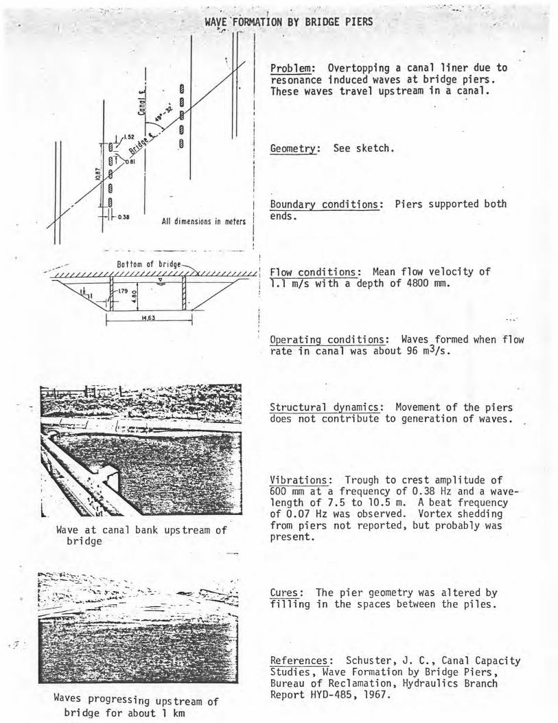
WAVE FORMATION BY BRIDGE PIERS
Problem: Overtopping a canal liner due to resonance induced waves at bridge piers. These waves travel upstream in a canal.
Geometry: See sketch.
038 All dimensions in meters
Boundary conditions: Piers supported both ends.
— Bottom of bridge Flow conditions: Mean flow velocity of 1.1 m/s with a depth of 4800 mm.
t~9 _1
Operating conditions: Waves formed when flow rate in canal was about 96 m3/s.
Structural dynamics: Movement of the piers does not contribute to generation of waves.
Vibrations: Trough to crest amplitude of 600 mm at a frequency of 0.38 Hz and a wave-length of 7.5 to 10.5 m. A beat frequency of 0.07 Hz was observed. Vortex shedding from piers not reported, but probably was present.
Wave at canal bank upstream of bridge
Cures: The pier geometry was altered by filling in the spaces between the piles.
References: Schuster, J. C., Canal Capacity Studies, Wave Formation by Bridge Piers, Bureau of Reclamation, Hydraulics Branch Report HYD-485, 1967.
Waves progressing upstream of bridge for about 1 km
Ln E 0 rn
w 0
J
a
FREQUENCY, HZ
CHART E ... i
HkED-CONE VALVES
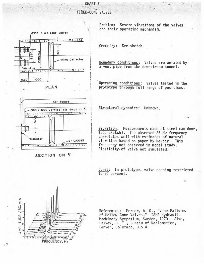
Problem: Severe vibrations of the valves and their operating mechanism.
2135 Fixed cone valves
Geometry: See sketch. O _ o o ~ i
o _ 0
__ tD Ring Deflector
0
i Boundary conditions: Valves are aerated by
Mandoor f a vent pipe from the downstream tunnel. o'
I 1
3660 1000 I Operating conditions: Valves tested in the
PLAN prototype through full range of positions.
_ Air tunnel
1980 X4270 Vertical air duct on f Structural dynamics: Unknown . i • o i
0 1
n
S = 0.0095
SECTION ON `L
Vibration: Measurements made at steel man-door, see sketch). The observed 85-Hz frequency correlates well with estimates of natural vibration based on paper by Mercer. This frequency not observed in model study. Elasticity.of valve not simulated.
Cures: In prototype, valve opening restricted to 80 percent.
References:. Mercer, A. G., "Vane Failures of Hollow-Cone Valves," IAHR Hydraulic Machinery Symposium, Sweden, 1970. Also, Falvey, H. T., Bureau of Reclamation, Denver, Colorado, U.S.A.
J-y--PENSTOCK RESONANCE
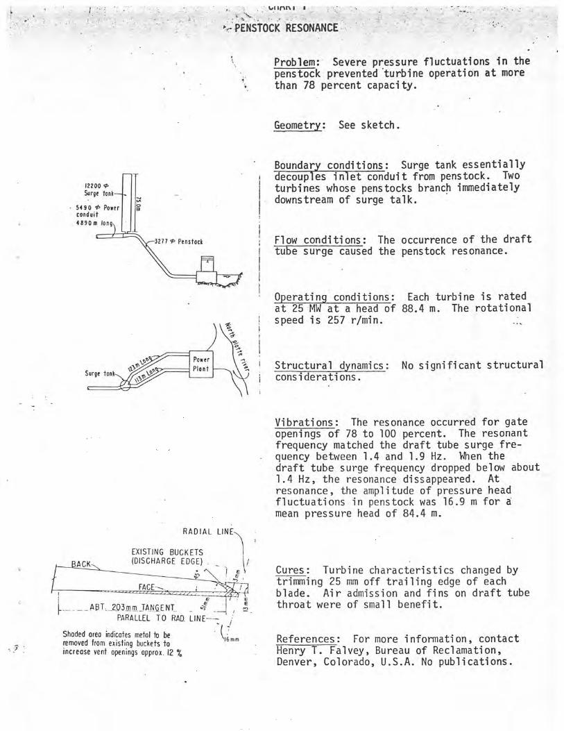
Problem: Severe pressure fluctuations in the penstock prevented turbine operation at more than 78 percent capacity.
Geometry: See sketch.
Boundary conditions: Surge tank essentially decoup es inlet conduit from penstock. Two turbines whose penstocks branch immediately downstream of surge talk.
Flow conditions: The occurrence of the draft tube surge caused the penstock resonance.
Operating conditions: Each turbine is rated at 25 MW at a head of 88.4 m. The rotational speed is 257 r/min.
Structural dynamics: No significant structural considerations.
122( Surg
5190 condui
IE90n
Surge
Power
Plant
Vibrations: The resonance occurred for gate openings of 78 to 100 percent. The resonant frequency matched the draft tube surge fre-quency between 1.4 and 1.9 Hz. When the draft tube surge frequency dropped below about 1.4 Hz, the resonance dissappeared. At resonance, the amplitude of pressure head fluctuations in penstock was 16.9 m for a
mean pressure head of 84.4 m.
RADIAL LINE\
EXISTING 1 BUCKETS
ACK (DISCHARGE EDGE) I E
FACE /
f
ABT_ 2O3mm_ TANGENT_ E
r PARALLEL TO RAD LINE--
` Shaded area indicates metal to be removed from existing buckets to
\I6mm
_ ' increase vent openings approx.12 %
Cures: Turbine characteristics changed by trimming 25 mm off trailing edge of each blade. Air admission and fins on draft tube throat were of small benefit.
References: For more information, contact Henry T. Falvey, Bureau of Reclamation, Denver, Colorado, U.S.A. No publications.
I
i
i
JA
CHART G
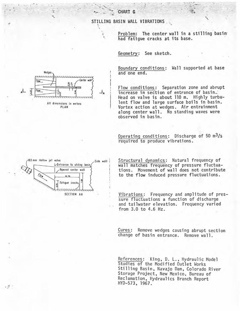
STILLING BASIN WALL VIBRATIONS.
Problem: The center wall in a stilling basin-had fatigue cracks dt its base.
Geometry: See sketch.
Wedges
Few_ Center wall o~
I
AL Flow
All dimensions in meters PLAN
183 mm Hollow jet valve
{-Entronce to stilling basin
2oe
enter wall
F\ Lcracks _
SECTION AA
Boundary conditions: Wall supported at base and one end.
Flow conditions: Separation zone and abrupt increase in section of entrance of basin.: Head on valve is about 110 m. Highly turbu-lent flow and large surface boils in basin. Vortex action at wedges. Air entrainment along center wall. No standing waves were observed in basin.
Operating conditions: Discharge of 50 m3/-s required to produce vibrations.
Structural dynamics: Natural frequency of wall matches frequency of pressure fluctua tions. Movement of wall does not contribute to the flow induced pressure fluctuations.
Vibrations: Frequency and amplitude of pres-sure fluctuations a function of discharge and tailwater elevation. Frequency varied from 3.0 to 4.6 Hz.
Cures: Remove wedges causing abrupt section change of basin entrance. Remove wall.
References: King, D. L., Hydraulic Model Studies of the Modified Outlet Works Stilling Basin, Navajo Dam, Colorado River Storage Project, New Mexico, Bureau of Reclamation, Hydraulics Branch Report HYD-573, 1967.
ontal center line
SECTION A-A
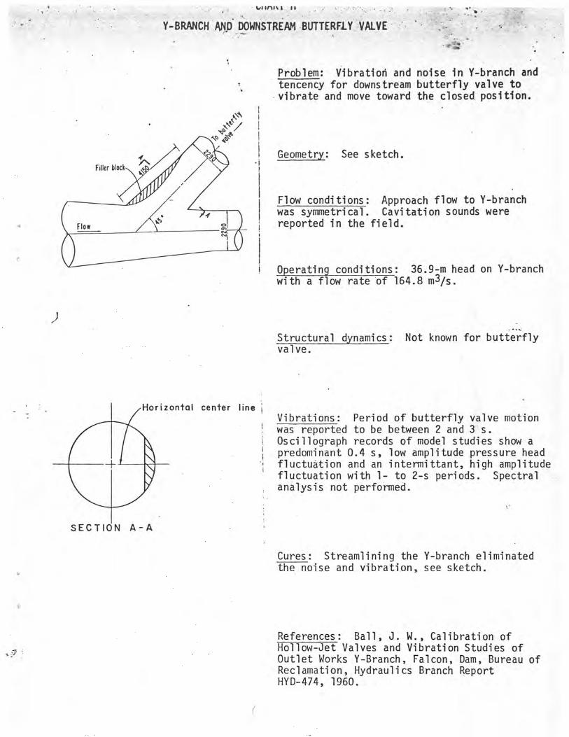
Y-BRANCH AND DOWNSTREAM BUTTERFLY, VALVE
Problem: Vibration and noise in Y-branch and tencency for downstream butterfly valve to vibrate and move toward the closed.position.
y~1
I Geometry: See sketch.
Flow conditions: Approach flow to Y-branch was symmetrical. Cavitation sounds were reported in the field.
i Operating conditions: 36.9-m head on Y-branch with a flow rate of 164.8 m3/s.
Structural dynamics: Not known for butterfly valve.
Vibrations: Period of butterfly valve motion was reported to be between 2 and 3 s. Oscillograph records of model studies show a predominant 0.4 s, low amplitude pressure head fluctuation and an intermittant, high amplitude fluctuation with 1- to 2-s periods. Spectral analysis not performed.
Cures: Streamlining the Y-branch eliminated the noise and vibration, see sketch.
References: Ball, J. W., Calibration of Hollow-Jet Valves and Vibration Studies of Outlet Works Y-Branch, Falcon, Dam, Bureau of Reclamation, Hydraulics Branch Report HYD-474, 1960.


![FLOW-INDUCED VIBRATIONS OF A LIGHT … · FLOW-INDUCED VIBRATIONS OF A ... non-linear oscillator for self-limiting its vibration amplitude are ... [13],OngorenandRockwell[14,15],Blevins[16],MittalandTezduyar](https://img.pdfslide.us/doc/110x75/5b83b77d7f8b9a31608def45/flow-induced-vibrations-of-a-light-flow-induced-vibrations-of-a-non-linear.jpg)