Embed Size (px)
Citation preview
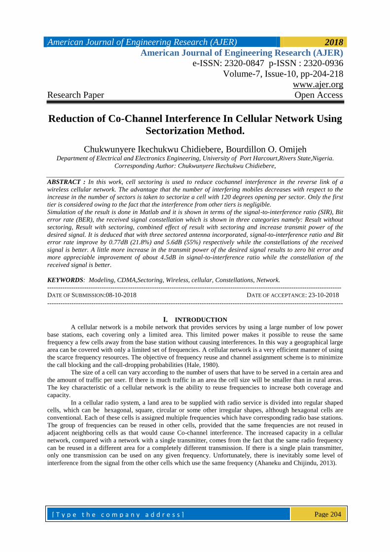
American Journal of Engineering Research (AJER) 2018
American Journal of Engineering Research (AJER)
e-ISSN: 2320-0847 p-ISSN : 2320-0936
Volume-7, Issue-10, pp-204-218
www.ajer.org
Research Paper Open Access
[ T y p e t h e c o m p a n y a d d r e s s ]
Page 204
Reduction of Co-Channel Interference In Cellular Network Using
Sectorization Method.
Chukwunyere Ikechukwu Chidiebere, Bourdillon O. Omijeh Department of Electrical and Electronics Engineering, University of Port Harcourt,Rivers State,Nigeria.
Corresponding Author: Chukwunyere Ikechukwu Chidiebere,
ABSTRACT : In this work, cell sectoring is used to reduce cochannel interference in the reverse link of a
wireless cellular network. The advantage that the number of interfering mobiles decreases with respect to the
increase in the number of sectors is taken to sectorize a cell with 120 degrees opening per sector. Only the first
tier is considered owing to the fact that the interference from other tiers is negligible.
Simulation of the result is done in Matlab and it is shown in terms of the signal-to-interference ratio (SIR), Bit
error rate (BER), the received signal constellation which is shown in three categories namely: Result without
sectoring, Result with sectoring, combined effect of result with sectoring and increase transmit power of the
desired signal. It is deduced that with three sectored antenna incorporated, signal-to-interference ratio and Bit
error rate improve by 0.77dB (21.8%) and 5.6dB (55%) respectively while the constellations of the received
signal is better. A little more increase in the transmit power of the desired signal results to zero bit error and
more appreciable improvement of about 4.5dB in signal-to-interference ratio while the constellation of the
received signal is better.
KEYWORDS: Modeling, CDMA,Sectoring, Wireless, cellular, Constellations, Network.
---------------------------------------------------------------------------------------------------------------------------------------
DATE OF SUBMISSION:08-10-2018 DATE OF ACCEPTANCE: 23-10-2018
--------------------------------------------------------------------------------------------------------------------------------------
I. INTRODUCTION
A cellular network is a mobile network that provides services by using a large number of low power
base stations, each covering only a limited area. This limited power makes it possible to reuse the same
frequency a few cells away from the base station without causing interferences. In this way a geographical large
area can be covered with only a limited set of frequencies. A cellular network is a very efficient manner of using
the scarce frequency resources. The objective of frequency reuse and channel assignment scheme is to minimize
the call blocking and the call-dropping probabilities (Hale, 1980).
The size of a cell can vary according to the number of users that have to be served in a certain area and
the amount of traffic per user. If there is much traffic in an area the cell size will be smaller than in rural areas.
The key characteristic of a cellular network is the ability to reuse frequencies to increase both coverage and
capacity.
In a cellular radio system, a land area to be supplied with radio service is divided into regular shaped
cells, which can be hexagonal, square, circular or some other irregular shapes, although hexagonal cells are
conventional. Each of these cells is assigned multiple frequencies which have corresponding radio base stations.
The group of frequencies can be reused in other cells, provided that the same frequencies are not reused in
adjacent neighboring cells as that would cause Co-channel interference. The increased capacity in a cellular
network, compared with a network with a single transmitter, comes from the fact that the same radio frequency
can be reused in a different area for a completely different transmission. If there is a single plain transmitter,
only one transmission can be used on any given frequency. Unfortunately, there is inevitably some level of
interference from the signal from the other cells which use the same frequency (Ahaneku and Chijindu, 2013).
American Journal of Engineering Research (AJER) 2018
[ T y p e t h e c o m p a n y a d d r e s s ]
Page 205
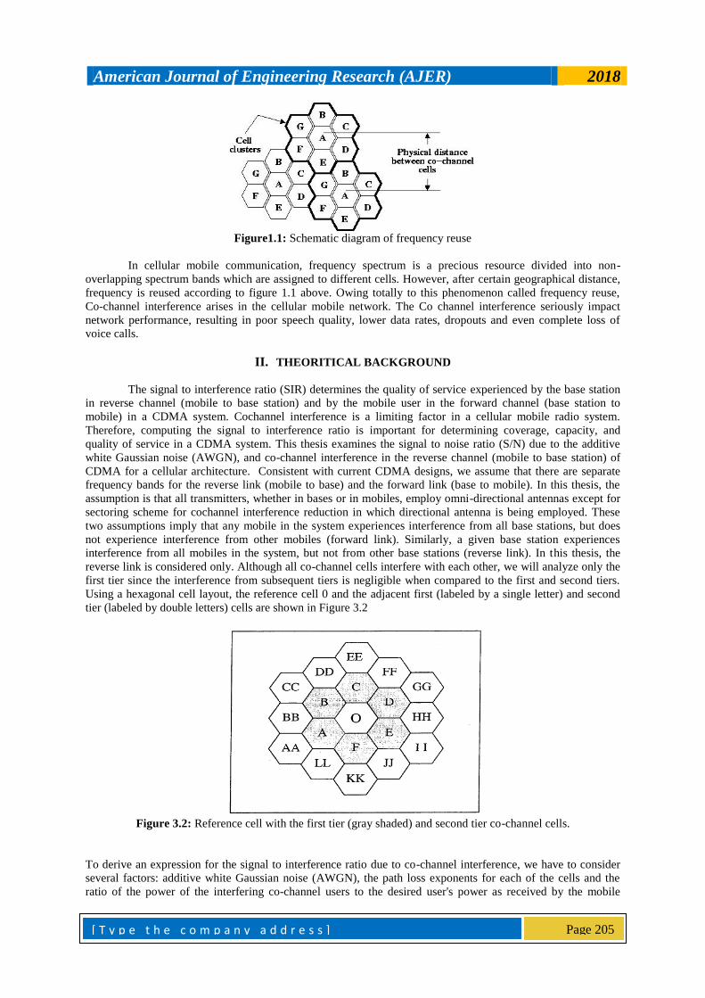
Figure1.1: Schematic diagram of frequency reuse
In cellular mobile communication, frequency spectrum is a precious resource divided into non-
overlapping spectrum bands which are assigned to different cells. However, after certain geographical distance,
frequency is reused according to figure 1.1 above. Owing totally to this phenomenon called frequency reuse,
Co-channel interference arises in the cellular mobile network. The Co channel interference seriously impact
network performance, resulting in poor speech quality, lower data rates, dropouts and even complete loss of
voice calls.
II. THEORITICAL BACKGROUND
The signal to interference ratio (SIR) determines the quality of service experienced by the base station
in reverse channel (mobile to base station) and by the mobile user in the forward channel (base station to
mobile) in a CDMA system. Cochannel interference is a limiting factor in a cellular mobile radio system.
Therefore, computing the signal to interference ratio is important for determining coverage, capacity, and
quality of service in a CDMA system. This thesis examines the signal to noise ratio (S/N) due to the additive
white Gaussian noise (AWGN), and co-channel interference in the reverse channel (mobile to base station) of
CDMA for a cellular architecture. Consistent with current CDMA designs, we assume that there are separate
frequency bands for the reverse link (mobile to base) and the forward link (base to mobile). In this thesis, the
assumption is that all transmitters, whether in bases or in mobiles, employ omni-directional antennas except for
sectoring scheme for cochannel interference reduction in which directional antenna is being employed. These
two assumptions imply that any mobile in the system experiences interference from all base stations, but does
not experience interference from other mobiles (forward link). Similarly, a given base station experiences
interference from all mobiles in the system, but not from other base stations (reverse link). In this thesis, the
reverse link is considered only. Although all co-channel cells interfere with each other, we will analyze only the
first tier since the interference from subsequent tiers is negligible when compared to the first and second tiers.
Using a hexagonal cell layout, the reference cell 0 and the adjacent first (labeled by a single letter) and second
tier (labeled by double letters) cells are shown in Figure 3.2
Figure 3.2: Reference cell with the first tier (gray shaded) and second tier co-channel cells.
To derive an expression for the signal to interference ratio due to co-channel interference, we have to consider
several factors: additive white Gaussian noise (AWGN), the path loss exponents for each of the cells and the
ratio of the power of the interfering co-channel users to the desired user's power as received by the mobile
American Journal of Engineering Research (AJER) 2018
[ T y p e t h e c o m p a n y a d d r e s s ]
Page 206
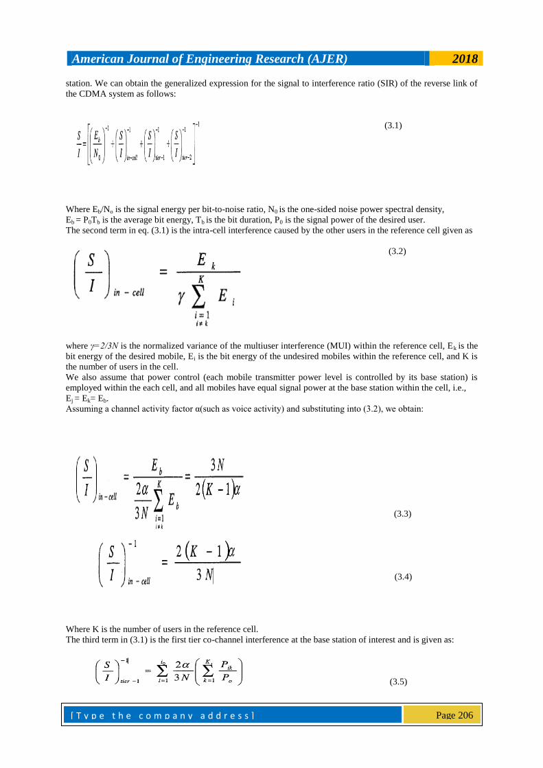
station. We can obtain the generalized expression for the signal to interference ratio (SIR) of the reverse link of
the CDMA system as follows:
(3.1)
Where Eb/No is the signal energy per bit-to-noise ratio, N0 is the one-sided noise power spectral density,
Eb = P0Tb is the average bit energy, Tb is the bit duration, P0 is the signal power of the desired user.
The second term in eq. (3.1) is the intra-cell interference caused by the other users in the reference cell given as
(3.2)
where γ=2/3N is the normalized variance of the multiuser interference (MUI) within the reference cell, Ek is the
bit energy of the desired mobile, Ei is the bit energy of the undesired mobiles within the reference cell, and K is
the number of users in the cell.
We also assume that power control (each mobile transmitter power level is controlled by its base station) is
employed within the each cell, and all mobiles have equal signal power at the base station within the cell, i.e.,
Ej = Ek= Eb.
Assuming a channel activity factor α(such as voice activity) and substituting into (3.2), we obtain:
(3.3)
(3.4)
Where K is the number of users in the reference cell.
The third term in (3.1) is the first tier co-channel interference at the base station of interest and is given as:
(3.5)
American Journal of Engineering Research (AJER) 2018
[ T y p e t h e c o m p a n y a d d r e s s ]
Page 207
where Po is the average received signal power at the reference base station, i0 is the number of the first tier co-
channel cells, Ki is the number of users within the ith
co-channel cell, Pik is the average received power at the
reference base station due to the kth
user in the ith
co-channel cell, and α is the channel activity factor.
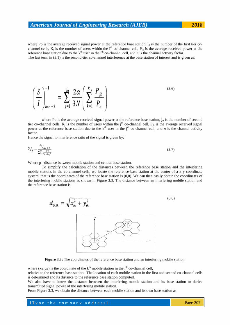
The last term in (3.1) is the second-tier co-channel interference at the base station of interest and is given as:
(3.6)
where Po is the average received signal power at the reference base station, j0 is the number of second
tier co-channel cells, Kj is the number of users within the jth
co-channel cell, Pjk is the average received signal
power at the reference base station due to the kth
user in the jth
co-channel cell, and α is the channel activity
factor.
Hence the signal to interference ratio of the signal is given by:
𝑆𝐼 =
𝑃04𝜋𝑃2
𝑃0
4𝜋𝐷𝑖2
𝑁𝑖=1
(3.7)
Where p= distance between mobile station and central base station.
To simplify the calculation of the distances between the reference base station and the interfering
mobile stations in the co-channel cells, we locate the reference base station at the center of a x-y coordinate
system, that is the coordinates of the reference base station is (0,0). We can then easily obtain the coordinates of
the interfering mobile stations as shown in Figure 3.3. The distance between an interfering mobile station and
the reference base station is
(3.8)
Figure 3.3: The coordinates of the reference base station and an interfering mobile station.
where (xik,yik) is the coordinate of the kth
mobile station in the ith
co-channel cell,
relative to the reference base station. The location of each mobile station in the first and second co-channel cells
is determined and its distance to the reference base station computed.
We also have to know the distance between the interfering mobile station and its base station to derive
transmitted signal power of the interfering mobile station.
From Figure 3.3, we obtain the distance between each mobile station and its own base station as
American Journal of Engineering Research (AJER) 2018
[ T y p e t h e c o m p a n y a d d r e s s ]
Page 208
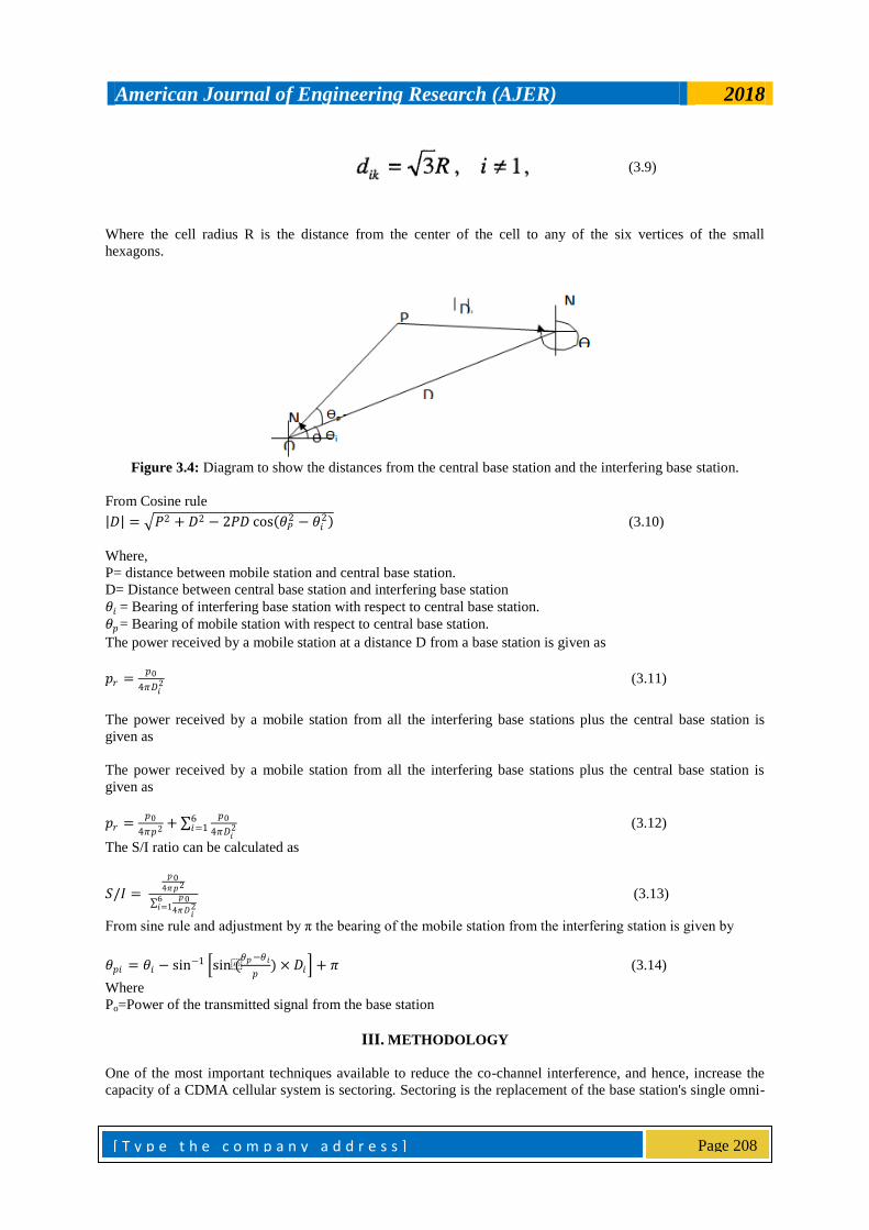
(3.9)
Where the cell radius R is the distance from the center of the cell to any of the six vertices of the small
hexagons.
Figure 3.4: Diagram to show the distances from the central base station and the interfering base station.
From Cosine rule
𝐷 = 𝑃2 + 𝐷2 − 2𝑃𝐷 cos 𝜃𝑃2 − 𝜃𝑖
2 (3.10)
Where,
P= distance between mobile station and central base station.
D= Distance between central base station and interfering base station
𝜃𝑖 = Bearing of interfering base station with respect to central base station.
𝜃𝑝= Bearing of mobile station with respect to central base station.
The power received by a mobile station at a distance D from a base station is given as
𝑝𝑟 =𝑝0
4𝜋𝐷𝑖2 (3.11)
The power received by a mobile station from all the interfering base stations plus the central base station is
given as
The power received by a mobile station from all the interfering base stations plus the central base station is
given as
𝑝𝑟 =𝑝0
4𝜋𝑝2 + 𝑝0
4𝜋𝐷𝑖2
6𝑖=1 (3.12)
The S/I ratio can be calculated as
𝑆/𝐼 =
𝑝04𝜋𝑝2
𝑝0
4𝜋𝐷𝑖2
6𝑖=1
(3.13)
From sine rule and adjustment by π the bearing of the mobile station from the interfering station is given by
𝜃𝑝𝑖 = 𝜃𝑖 − sin−1 sin(𝜃𝑝−𝜃𝑖
𝑝) × 𝐷𝑖 + 𝜋
(3.14)
Where
Po=Power of the transmitted signal from the base station
III. METHODOLOGY
One of the most important techniques available to reduce the co-channel interference, and hence, increase the
capacity of a CDMA cellular system is sectoring. Sectoring is the replacement of the base station's single omni-
American Journal of Engineering Research (AJER) 2018
[ T y p e t h e c o m p a n y a d d r e s s ]
Page 209
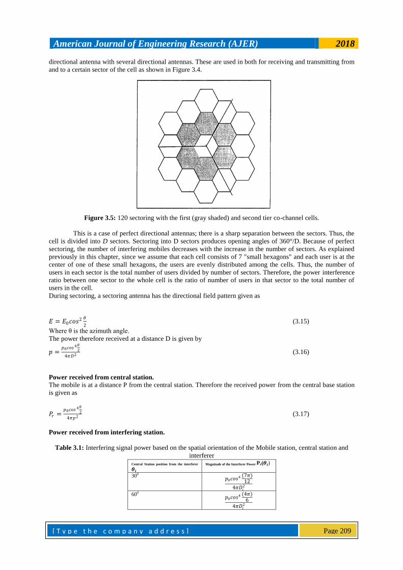
directional antenna with several directional antennas. These are used in both for receiving and transmitting from
and to a certain sector of the cell as shown in Figure 3.4.
Figure 3.5: 120 sectoring with the first (gray shaded) and second tier co-channel cells.
This is a case of perfect directional antennas; there is a sharp separation between the sectors. Thus, the
cell is divided into D sectors. Sectoring into D sectors produces opening angles of 360°/D. Because of perfect
sectoring, the number of interfering mobiles decreases with the increase in the number of sectors. As explained
previously in this chapter, since we assume that each cell consists of 7 "small hexagons" and each user is at the
center of one of these small hexagons, the users are evenly distributed among the cells. Thus, the number of
users in each sector is the total number of users divided by number of sectors. Therefore, the power interference
ratio between one sector to the whole cell is the ratio of number of users in that sector to the total number of
users in the cell.
During sectoring, a sectoring antenna has the directional field pattern given as
𝐸 = 𝐸0𝑐𝑜𝑠2 𝜃
2 (3.15)
Where θ is the azimuth angle.
The power therefore received at a distance D is given by
𝑝 =𝑝0𝑐𝑜𝑠 4𝜃
2
4𝜋𝐷2 (3.16)
Power received from central station.
The mobile is at a distance P from the central station. Therefore the received power from the central base station
is given as
𝑃𝑟 =𝑝0𝑐𝑜𝑠 4𝜃
2
4𝜋𝑝2 (3.17)
Power received from interfering station.
Table 3.1: Interfering signal power based on the spatial orientation of the Mobile station, central station and
interferer Central Station position from the interferer
𝜽𝒊 Magnitude of the Interferer Power Pr(𝜽𝒊)
300 𝑝0𝑐𝑜𝑠
4 (7𝜋)12
4𝜋𝐷𝑖2
600 𝑝0𝑐𝑜𝑠
4 (4𝜋)6
4𝜋𝐷𝑖2
American Journal of Engineering Research (AJER) 2018
[ T y p e t h e c o m p a n y a d d r e s s ]
Page 210
900 𝑝0𝑐𝑜𝑠
4 (7𝜋)12
4𝜋𝐷𝑖2
1200 𝑝0𝑐𝑜𝑠
4 (5𝜋)6
4𝜋𝐷𝑖2
1500 𝑝0𝑐𝑜𝑠
4 11𝜋 12
4𝜋𝐷𝑖2
1800
𝑝0𝑐𝑜𝑠 4𝜋
4𝜋𝐷𝑖2
The total power from Interfering Stations
= 1
4𝜋𝐷𝑖2
𝑃0𝑐𝑜𝑠 4(𝜃𝑖+𝜋 )
2
6𝑖=1 (3.18)
𝜃𝑖 = (π
6,
π
3,
π
2,
2π
3,
5π
6, π)
The S/I ratio can be calculated thus as
S/I=
𝑃0𝑐𝑜𝑠 4(𝜃)2
4𝜋𝑃2
1
4𝜋𝐷𝑖2 𝑃0
𝑐𝑜𝑠 4(𝜃𝑖+𝜋 )2
6𝑖=1
(3.19)
When sectoring is applied, the location of each mobile station in the first tier co-channel cells is determined and
its distance to the reference base station computed using cosine rule as shown in the equation 3.10 above:
𝐷𝑖 = Distance between interfering base station and mobile station.
𝜃𝑖 = Bearing of interfering base station with respect to central base station.
𝜃𝑝= Bearing of mobile station with respect to central base station.
With application of Sectoring, the power of the transmitted signal being the power received by mobile stations
from all base station is shown in equation (3.19) above
Where the angle 𝜃𝑝𝑖 = Bearing of mobile station with respect to interfering station, as shown the equation (3.14)
above
That is the reference angle to which the sectoring angles are being measured which determines the direction of
the antenna and its coverage to a particular number of interfering mobile cells.
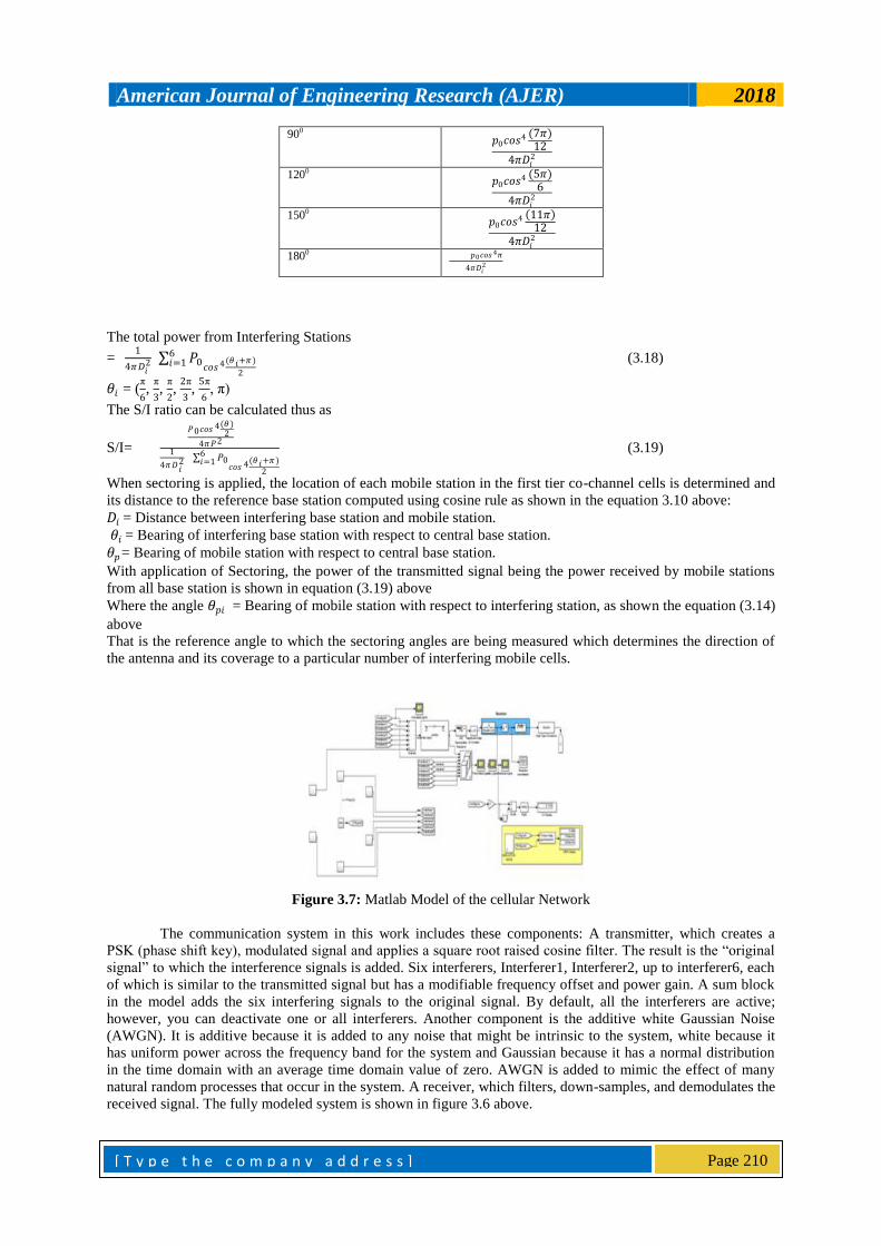
Figure 3.7: Matlab Model of the cellular Network
The communication system in this work includes these components: A transmitter, which creates a
PSK (phase shift key), modulated signal and applies a square root raised cosine filter. The result is the “original
signal” to which the interference signals is added. Six interferers, Interferer1, Interferer2, up to interferer6, each
of which is similar to the transmitted signal but has a modifiable frequency offset and power gain. A sum block
in the model adds the six interfering signals to the original signal. By default, all the interferers are active;
however, you can deactivate one or all interferers. Another component is the additive white Gaussian Noise
(AWGN). It is additive because it is added to any noise that might be intrinsic to the system, white because it
has uniform power across the frequency band for the system and Gaussian because it has a normal distribution
in the time domain with an average time domain value of zero. AWGN is added to mimic the effect of many
natural random processes that occur in the system. A receiver, which filters, down-samples, and demodulates the
received signal. The fully modeled system is shown in figure 3.6 above.
American Journal of Engineering Research (AJER) 2018
[ T y p e t h e c o m p a n y a d d r e s s ]
Page 211
IV. SIMULATIONS, NUMERICAL RESULTS AND DISCUSSIONS
Table 3.2 Data collected
S/NO PARAMETERS VALUES
1. Distance between
mobile station central base station, P
4m
2. Distance between
central base station and interfering base
stations, D
6m
3. Beam width, BW 200e3
4. Signal power of the actual signal, P0
1.0dB
5. Signal band width, B 2MHz
6. Signal type PSK
7. Signal sampling time 1e-6s
8. Signal bit rate 1e6/s
9. Up-sampling filter factor
8
10 Inclination angle of
base station to mobile station
45 Degrees
4.1.1 Result Analysis of Case 1 simulation
The first simulation case was carried out without incorporating the proposed cochannel reduction scheme into
the system. At this point the results are presented and scoped out to graphically illustrate the behaviour of the
system operating with six interfering signals transmitted alongside with the actual signal. The result is as shown
below in figure 4.1.
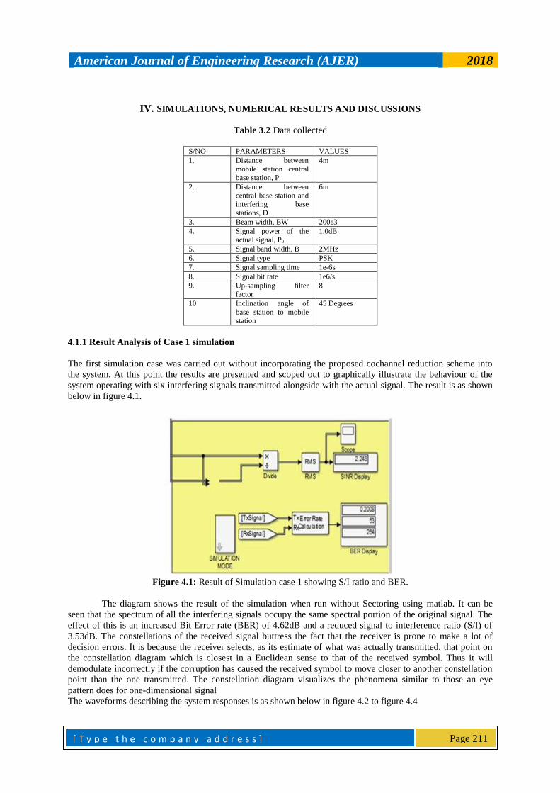
Figure 4.1: Result of Simulation case 1 showing S/I ratio and BER.
The diagram shows the result of the simulation when run without Sectoring using matlab. It can be
seen that the spectrum of all the interfering signals occupy the same spectral portion of the original signal. The
effect of this is an increased Bit Error rate (BER) of 4.62dB and a reduced signal to interference ratio (S/I) of
3.53dB. The constellations of the received signal buttress the fact that the receiver is prone to make a lot of
decision errors. It is because the receiver selects, as its estimate of what was actually transmitted, that point on
the constellation diagram which is closest in a Euclidean sense to that of the received symbol. Thus it will
demodulate incorrectly if the corruption has caused the received symbol to move closer to another constellation
point than the one transmitted. The constellation diagram visualizes the phenomena similar to those an eye
pattern does for one-dimensional signal
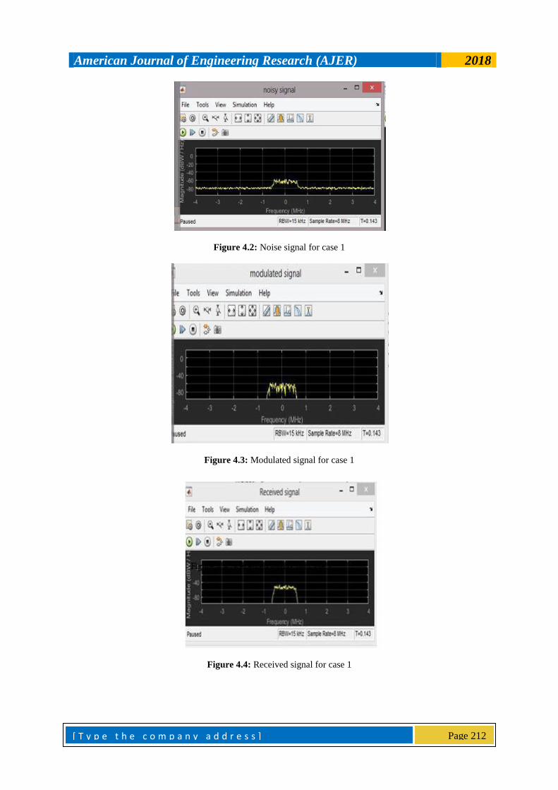
The waveforms describing the system responses is as shown below in figure 4.2 to figure 4.4
American Journal of Engineering Research (AJER) 2018
[ T y p e t h e c o m p a n y a d d r e s s ]
Page 212
Figure 4.2: Noise signal for case 1
Figure 4.3: Modulated signal for case 1
Figure 4.4: Received signal for case 1
American Journal of Engineering Research (AJER) 2018
[ T y p e t h e c o m p a n y a d d r e s s ]
Page 213
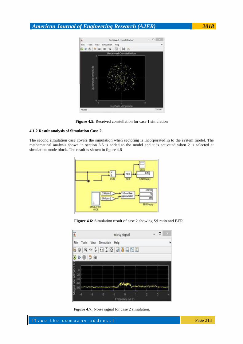
Figure 4.5: Received constellation for case 1 simulation
4.1.2 Result analysis of Simulation Case 2
The second simulation case covers the simulation when sectoring is incorporated in to the system model. The
mathematical analysis shown in section 3.5 is added to the model and it is activated when 2 is selected at
simulation mode block. The result is shown in figure 4.6
Figure 4.6: Simulation result of case 2 showing S/I ratio and BER.
Figure 4.7: Noise signal for case 2 simulation.
American Journal of Engineering Research (AJER) 2018
[ T y p e t h e c o m p a n y a d d r e s s ]
Page 214
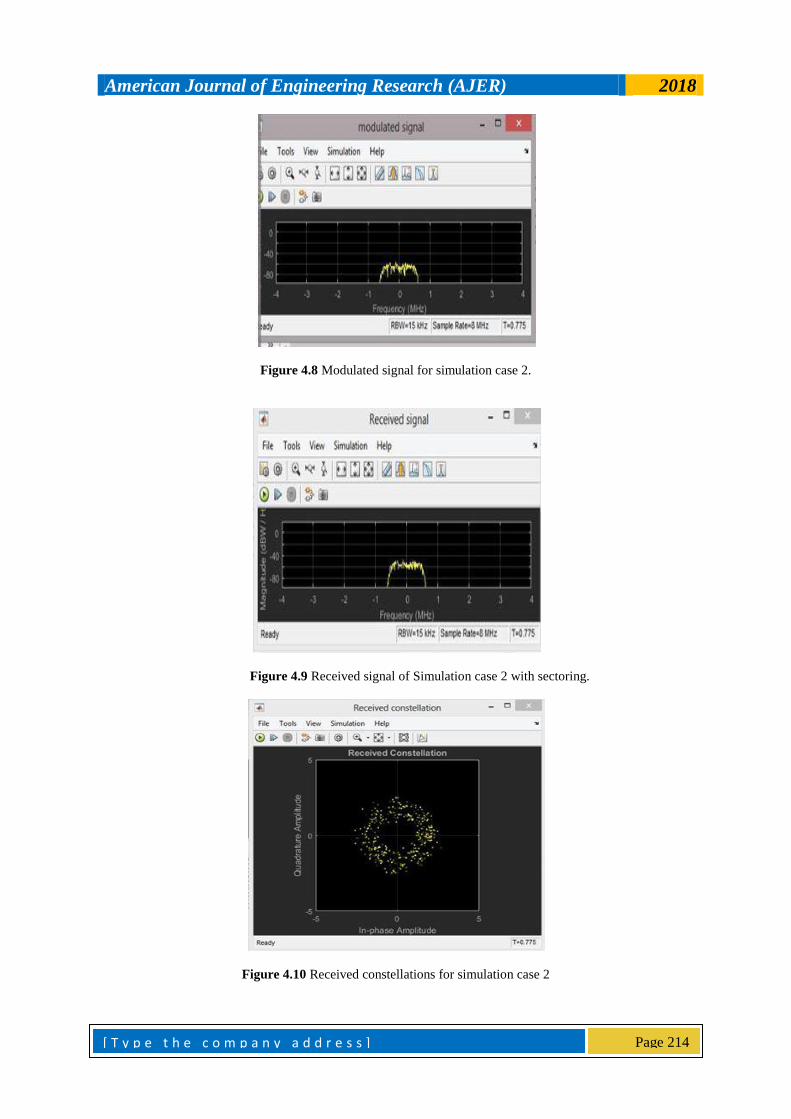
Figure 4.8 Modulated signal for simulation case 2.
Figure 4.9 Received signal of Simulation case 2 with sectoring.
Figure 4.10 Received constellations for simulation case 2
American Journal of Engineering Research (AJER) 2018
[ T y p e t h e c o m p a n y a d d r e s s ]
Page 215
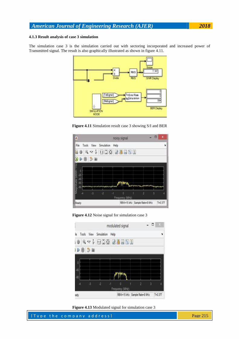
4.1.3 Result analysis of case 3 simulation
The simulation case 3 is the simulation carried out with sectoring incorporated and increased power of
Transmitted signal. The result is also graphically illustrated as shown in figure 4.11.
Figure 4.11 Simulation result case 3 showing S/I and BER
Figure 4.12 Noise signal for simulation case 3
Figure 4.13 Modulated signal for simulation case 3
American Journal of Engineering Research (AJER) 2018
[ T y p e t h e c o m p a n y a d d r e s s ]
Page 216
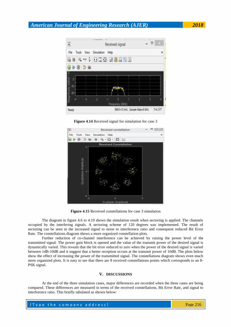
Figure 4.14 Received signal for simulation for case 3
Figure 4.15 Received constellations for case 3 simulation
The diagram in figure 4.6 to 4.10 shows the simulation result when sectoring is applied. The channels
occupied by the interfering signals. A sectoring scheme of 120 degrees was implemented. The result of
sectoring can be seen in the increased signal to noise to interference ratio and consequent reduced Bit Error
Rate. The constellations diagram shows a more organized constellation plots.
Further reduction of co-channel interference can be achieved by raising the power level of the
transmitted signal. The power gain block is opened and the value of the transmit power of the desired signal is
dynamically varied. This reveals that the bit error reduced to zero when the power of the desired signal is varied
between 1dB-10dB and it suggest that a better reception occurs at the transmit power of 10dB. The plots below
show the effect of increasing the power of the transmitted signal. The constellations diagram shows even much
more organized plots. It is easy to see that there are 8 received constellations points which corresponds to an 8-
PSK signal.
V. DISCUSSIONS
At the end of the three simulation cases, major differences are recorded when the three cases are being
compared. These differences are measured in terms of the received constellations, Bit Error Rate, and signal to
interference ratio. This briefly tabulated as shown below:
American Journal of Engineering Research (AJER) 2018
[ T y p e t h e c o m p a n y a d d r e s s ]
Page 217
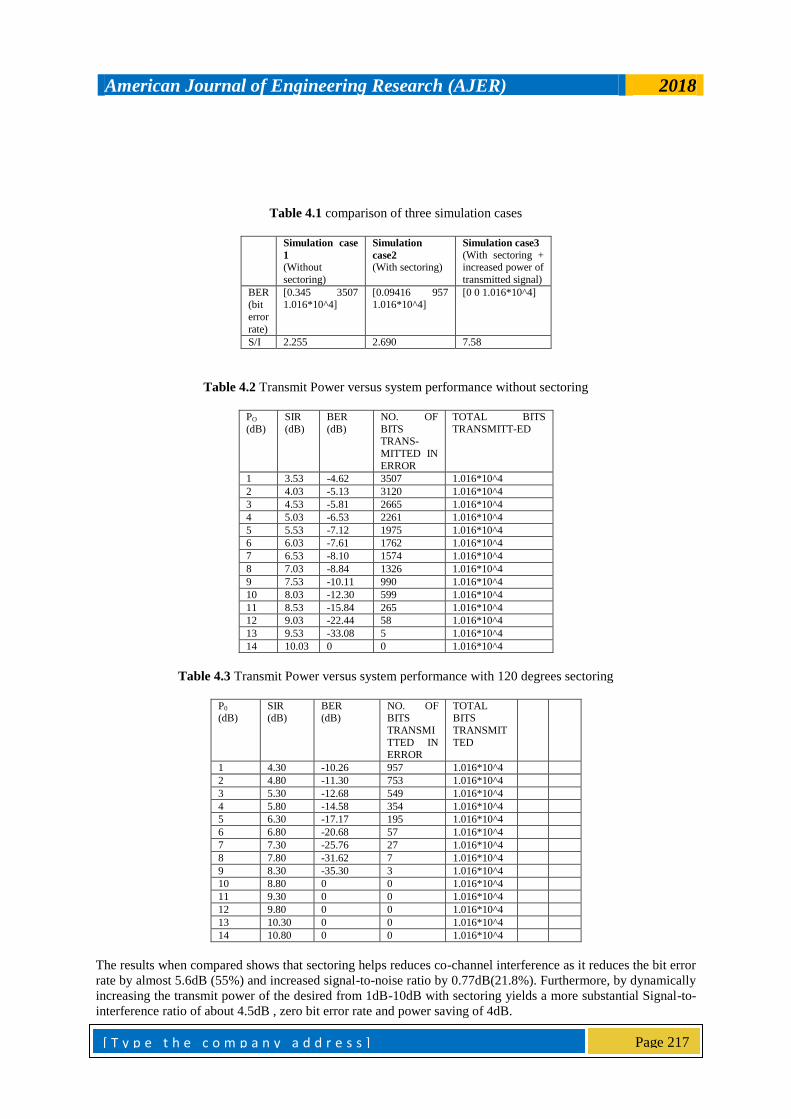
Table 4.1 comparison of three simulation cases
Simulation case
1
(Without
sectoring)
Simulation
case2
(With sectoring)
Simulation case3
(With sectoring + increased power of
transmitted signal)
BER (bit
error
rate)
[0.345 3507 1.016*10^4]
[0.09416 957 1.016*10^4]
[0 0 1.016*10^4]
S/I 2.255 2.690 7.58
Table 4.2 Transmit Power versus system performance without sectoring
PO
(dB)
SIR
(dB)
BER
(dB)
NO. OF
BITS TRANS-
MITTED IN
ERROR
TOTAL BITS
TRANSMITT-ED
1 3.53 -4.62 3507 1.016*10^4
2 4.03 -5.13 3120 1.016*10^4
3 4.53 -5.81 2665 1.016*10^4
4 5.03 -6.53 2261 1.016*10^4
5 5.53 -7.12 1975 1.016*10^4
6 6.03 -7.61 1762 1.016*10^4
7 6.53 -8.10 1574 1.016*10^4
8 7.03 -8.84 1326 1.016*10^4
9 7.53 -10.11 990 1.016*10^4
10 8.03 -12.30 599 1.016*10^4
11 8.53 -15.84 265 1.016*10^4
12 9.03 -22.44 58 1.016*10^4
13 9.53 -33.08 5 1.016*10^4
14 10.03 0 0 1.016*10^4
Table 4.3 Transmit Power versus system performance with 120 degrees sectoring
P0
(dB) SIR (dB)
BER (dB)
NO. OF BITS
TRANSMI
TTED IN ERROR
TOTAL BITS
TRANSMIT
TED
1 4.30 -10.26 957 1.016*10^4
2 4.80 -11.30 753 1.016*10^4
3 5.30 -12.68 549 1.016*10^4
4 5.80 -14.58 354 1.016*10^4
5 6.30 -17.17 195 1.016*10^4
6 6.80 -20.68 57 1.016*10^4
7 7.30 -25.76 27 1.016*10^4
8 7.80 -31.62 7 1.016*10^4
9 8.30 -35.30 3 1.016*10^4
10 8.80 0 0 1.016*10^4
11 9.30 0 0 1.016*10^4
12 9.80 0 0 1.016*10^4
13 10.30 0 0 1.016*10^4
14 10.80 0 0 1.016*10^4
The results when compared shows that sectoring helps reduces co-channel interference as it reduces the bit error
rate by almost 5.6dB (55%) and increased signal-to-noise ratio by 0.77dB(21.8%). Furthermore, by dynamically
increasing the transmit power of the desired from 1dB-10dB with sectoring yields a more substantial Signal-to-
interference ratio of about 4.5dB , zero bit error rate and power saving of 4dB.
American Journal of Engineering Research (AJER) 2018
[ T y p e t h e c o m p a n y a d d r e s s ]
Page 218
VI. CONCLUSION
This thesis employs 120 degrees sectoring to reduce co-channel interference in wireless cellular
network. Only first tier is considered owing to the fact that the interference from the subsequent tiers is
negligible. Similarly, only the reverse link of a code division multiple access (CDMA) system is considered and
because of sectoring, the number of interfering mobiles decreases with increase in the number of sectors. The
result is shown in terms of signal to interference ratio (SIR), bit error rate (BER) and the received signal
constellation.
Simulation of the system is done in matlab and in three cases namely, case 1, case 2 and case 3. Case 1
shows the behaviours of the system without sectoring. The result bit error rate and signal-to- interference ratio
of 4.62dB and 3.53dB respectively. The scattered constellation of the received signal implies that the receiver is
prone to make a lot of decision errors. Case 2 result shows 55% (5.6dB) and 21.8% (0.77dB) improvement in
the bit error rate (BER) and signal-to-interference ratio (SIR) respectively. Case 3 shows the behavior of the
system due to the combined effect of dynamic increase transmits power of the desired signal and 120 degrees
sectoring. The bit error rate dropped to zero with additional 4.5dB improvement in signal to interference ratio.
This suggests that this research will be well suited in a cellular network whose architecture employs dynamic
transmit power mechanism.
REFERENCES [1]. Abhinav, K. and Vinay, V. (2014). Study on improving coverage area by cell splitting and cell sectoring methods in cellular system.
International Journal of advanced research in computer science and software engineering. Vol. 4, Pp. 813-814.
[2]. Adem Durak. (1999). “Evaluation and methods to reduce Cochannel interference on the reverse channel of a CDMA cellular system”, DTIC quality inspected, Pp. 18-20.
[3]. Ahaneku, M.A. & Chinjundu, V.C. (2013). “Frequency Reuse and Implications of Limited Network Resources in Cellular Mobile
Systems”, Pp. 167-171. [4]. Ahmed, Mohammed Abdelsalam Ahmed and Marsland, I. M. (2008). “Cochannel Interference Cancellation in Wireless Cellular
Networks”. Pp. 698-702.
[5]. Andrea, Goldsmith. (2004). “Wireless communications”. Stanford University. Pp. 10-14. [6]. Ball, C.F., and Ivanov, H.K., (2005). “Spectrum efficiency evaluation for different wireless technology based on traffic modeling”,
IEEE international Symposium on personal indoor and mobile radio communications workshop,Vol. 3,Pp. 2055-2061.
[7]. Carl, Carter. (1997). Principles of global positioning system. Allen Osborne Associates, Pp. 1- 9.
[8]. Elena, Lopez-Agulera and Jordi, Casademont. (2006). A transmit power control proposal for IEEE 802.11 cellular networks. IEEE,
6th international workshop on application and services in wireless networks. Pp. 1-8.
[9]. Hale, W.K. (1980).“Frequency Assignment Theory and Application”. ww.ieeexplore.iece.org. Pp. 1497-1514. [10]. Ho-Shin, Cho. (2001). “Protection against Cochannel Interference from Neighboring Cells Using Down-Tilting of Antenna Beams”.
Pp. 1553-1557.
[11]. Jens, Zander. (1994). Transmitter power control for Cochannel interference Management in cellular radio systems. Springer science and business media, Pp. 161-175.
[12]. Jiang, L.I., Dongdong, L.I., Jaber, A., Khoja, Qilian, Liang, Micheal, Mary, T. and Vasant, K. Probhu. (2003). “Overcoming
Cochannel Interference in TDMA systems Using SOM Equalizer”. Pp. 123-126. [13]. Minh, A. Nguyen. (2005). “Interference Cancellation Receiver”, NASA publishers, Pp. 1-6.
[14]. Muhammed, Ali Qureshi, Alodul, Aziz and Hussaia, Bakhsh. (2010). CIR improvement in a cellular mobile system using
Beamforming and power control. IEEE, Pp. 294-297. [15]. Nisha, Sunil Kumar and Jyoti, Bhatnager. (2013). Hand off strategies in cellular system. International Journal of new trends in
electronics and communication. Vol. 1, Pp. 22-26.
[16]. Ohaneme. C.O., Idigo, V.E., and Ifeagwu, E.N. (2012). Analysis of interference and channel capacity in a CDMA wireless network using dynamic channel assignment strategy. International journal of computer networks and communication. vol 4, No. 5, Pp. 149-
163.
[17]. Reza, Berang. (1998). “Cochannel Interference Cancellation in Mobile Cellular Communication Systems. Victoria University of Technology Library”, Kluer Academic Publishers, Pp. 21-71.
[18]. Saad, G. Kiani and David, Gesbert. (2006). Optimal and distributed scheduling for multicell capacity maximization. IEEE
International symposium on information theory, Pp. 1-29. [19]. Sirikiat, Lek Ariyavisitakul, Jack, H. Winters and Nelson R. Sollenberger. (2000). “Joint Equalization and Interference
[20]. Suppression for High Data Rate Wireless Systems”, IEEE Journal on Selected Areas in Communications, Vol. 18.
[21]. Tasher, Ali Sheikh, Deboray, Muchahary and Khanjan, Changmai. (2014). A survey of reduction the interference on cellular communication system. International Journal of computer application . Vol.95, Pp. 40-41.
[22]. Teruya, Fujii and Masayuki, Sakamoto. (1988). Reduction of Cochannel interference in cellular systems by intra-zone channel
reassignment IEEE, Pp. 668-672. [23]. Tuan NGNYEN (2006), “Null Depth Trade off for output Power Reduction in a Downlink Adaptive Antenna Array”, IEEE
International Symposium on Wireless Personal Multimedia Communications-Bankok, 2000.
Chukwunyere Ikechukwu Chidiebere " Reduction of Co-Channel Interference In Cellular Network
Using Sectorization Method "American Journal of Engineering Research (AJER), vol. 7, no. 10, 2018,