Embed Size (px)
Citation preview
74 F. GLEISSNER, S. HANUS, CO-CHANNEL AND ADJACENT CHANNEL INTERFERENCE MEASUREMENT...
Co-channel and Adjacent Channel Interference Measurement of UMTS and GSM/EDGE Systems
in 900 MHz Radio Band
Filip GLEISSNER, Stanislav HANUS
Dept. of Radio Electronics, Brno University of Technology, Purkyňova 118, 612 00 Brno, Czech Republic
[email protected], [email protected]
Abstract. This paper is concerned with inter-system and intra-system interference measurements of 2.5G and 3G mobile communication systems. The both systems UMTS and GSM/EDGE are assumed to operate in a common radio band of 900 MHz. The main system parameters are briefly introduced as well as the measurement scenario. Several simulations and key measurements were per-formed. Important results are described and commented along with a graphical representation, namely bit error ratio (BER) dependence on carrier to noise ratio (CNR) in the presence of additive white Gaussian noise (AWGN), the measurement of adjacent channel interference ratio of each system, the coexistence of both systems in same band and the impact of a carrier offset on BER.
Keywords UMTS, GSM/EDGE, interference, measurement, co-channel, adjacent channel, BER, carrier offset.
1. Introduction The radio spectrum becomes occupied very densely
nowadays. Thus, radio planning and management is a vital question of present studies and papers.
The performance of any radio system is interference dependent. The aim of this work is the coexistence investi-gation of the mobile wireless systems UMTS and GSM/EDGE. The main aspect observed is co-channel and adjacent channel interference, while both the systems oper-ate in the common radio band of 900 MHz.
Frequency planning is assumed, in which a UMTS carrier is sandwiched between existing GSM carriers with sufficient guard bands between the carriers (see Fig. 1). The size of guard bands is the subject of examination, because there could be possible capacity loss due to the adjacent channel interference.
Standard rules for the guard bands are based on nominal assumptions about the adjacent channel selectivity (ACS) of the receivers and the adjacent channel leakage
(ACLR) of the transmitters. It has been shown that inter-ference from GSM uplink onto the UMTS uplink is the dominant cause of capacity loss. The use of adaptive filters on UMTS Node B transceivers, with the ability to selec-tively reject interfering GSM uplink signals, can essentially reduce the size of guard bands [4].
Fig. 1. Frequency plan – “sandwich” type of UMTS band
between GSM bands.
2. Measurement Scenario It is very important to distinguish a measurement in a
laboratory and a real-time measurement on an operating base station. There are clearly defined conditions in a labo-ratory in terms of fixed parameters. Moreover, the radio channel is simulated in a deterministic way. This method is suitable for cases that need reproducible testing, while the measurement in the real network reveals the real system behavior and operation. However, this method needs portable equipment and a direct access to the network [1].
In these terms experimental measurement in the lab conditions was chosen. The direct access to the real net-work is not possible due to the non-existence of pure UMTS-FDD network in the Czech Republic.
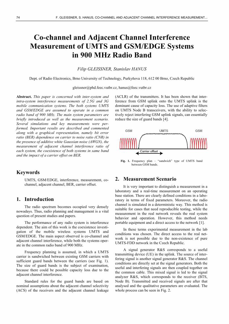
A signal generator R&S corresponds to a useful transmitting device (UE) in the uplink. The source of inter-fering signal is another signal generator R&S. The channel conditions are directly set at the signal generators. Both the useful and interfering signals are then coupled together on the common cable. This mixed signal is led to the signal analyzer R&S, which corresponds to the receiver (BTS, Node B). Transmitted and received signals are after that analysed and the qualitative parameters are evaluated. The whole process can be seen in Fig. 2.
RADIOENGINEERING, VOL. 17, NO. 3, SEPTEMBER 2008 75
2.1 The System Overviews The UMTS system is based on direct sequence code
division multiple access (DS-CDMA). The spreading se-quence has a constant chip rate equal to 3.84 Mchip/s. The user data signal has a variable bit rate from 15 kbit/s to 960 kbit/s in the uplink direction (from a mobile station to a base station). The rate between the chip rate and bit rate is called spreading factor (SF). The values of SF are from 4 to 256 and are always a power of 2.
Fig. 2. Measurement scenario.
The basic operations, which are performed with the signal, are spreading and scrambling. The signal is first spread by the OVSF code (Walsh codes are used). This leads to an extension of the signal band to approximately 5 MHz. After that, the wideband signal is scrambled by scrambling code (S(2) or Gold codes are used). This operation does not cause additional extension of the band-width.
In UMTS uplink, the channels are I-Q/code multi-plexed. This is also called dual-channel QPSK modulation. The carrier raster is 200 kHz. More information can be found, for example, in [2] and [5].
The GSM/EDGE system (frequently referred to as EGPRS – Enhanced General Packet Radio Service) is a direct evolution of GPRS. The same concept and archi-tecture are used – 200 kHz channel bandwidth, the combi-nation of FDMA/TDMA multiple access, 8 timeslots, etc [6]. The main changes are in the radio interface in com-parison with GPRS.
A new modulation and coding scheme (MCS) enables optimization of transfer rate with respect to radio environ-ment conditions. Data bit rates (on the RLC/MAC layer) start at 8.8 kbit/s per slot (MCS-1) and end at 59.2 kbit/s per slot (MCS-9) [6]. The first four schemes utilize the GMSK modulation, the remaining five schemes utilize the 8-PSK modulation.
2.2 Simulation Setup Both physical layer models of the system have been
designed and implemented in Matlab according to the 3GPP standards and recommendation [5] – [11].
In the UMTS mode, UE maintains data connection with a variable bit rate, which is set by the spreading fac-tor. It starts from SF = 256 and after 1000 frames it is switched in a descending order until SF = 4 is reached.
In the GSM/EDGE mode, UE also maintains data connection with a variable bit rate, which is here set by modulation and by the coding scheme. It starts from MCS-1 and after 1000 frames it is switched in an ascending order until MCS-9 is reached. No retransmissions are considered. Forward error correction is assumed only.
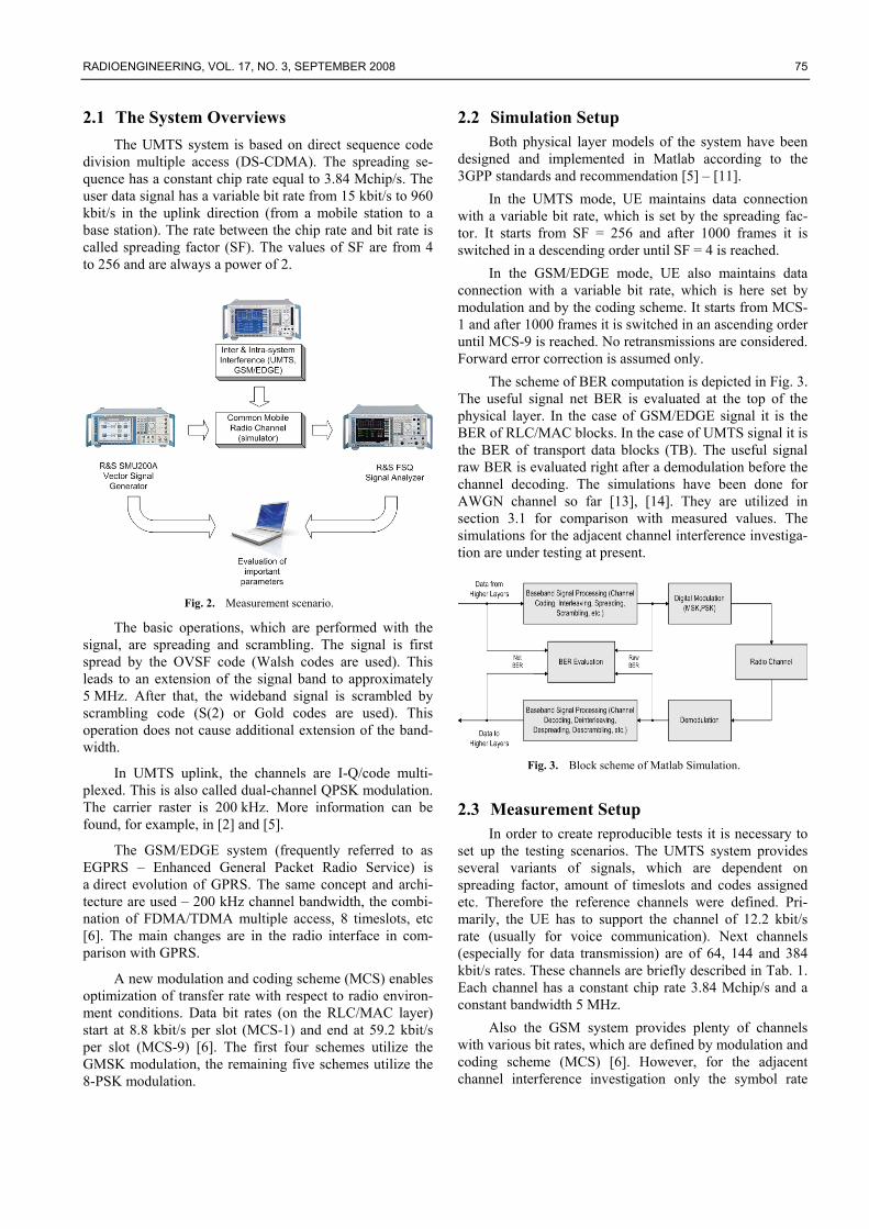
The scheme of BER computation is depicted in Fig. 3. The useful signal net BER is evaluated at the top of the physical layer. In the case of GSM/EDGE signal it is the BER of RLC/MAC blocks. In the case of UMTS signal it is the BER of transport data blocks (TB). The useful signal raw BER is evaluated right after a demodulation before the channel decoding. The simulations have been done for AWGN channel so far [13], [14]. They are utilized in section 3.1 for comparison with measured values. The simulations for the adjacent channel interference investiga-tion are under testing at present.
Fig. 3. Block scheme of Matlab Simulation.
2.3 Measurement Setup In order to create reproducible tests it is necessary to
set up the testing scenarios. The UMTS system provides several variants of signals, which are dependent on spreading factor, amount of timeslots and codes assigned etc. Therefore the reference channels were defined. Pri-marily, the UE has to support the channel of 12.2 kbit/s rate (usually for voice communication). Next channels (especially for data transmission) are of 64, 144 and 384 kbit/s rates. These channels are briefly described in Tab. 1. Each channel has a constant chip rate 3.84 Mchip/s and a constant bandwidth 5 MHz.
Also the GSM system provides plenty of channels with various bit rates, which are defined by modulation and coding scheme (MCS) [6]. However, for the adjacent channel interference investigation only the symbol rate
76 F. GLEISSNER, S. HANUS, CO-CHANNEL AND ADJACENT CHANNEL INTERFERENCE MEASUREMENT...
270.833 ks/s, modulation GMSK or 8-PSK and the channel bandwidth 200 kHz is important.
Parameter Channel 1
Channel 2
Channel 3
Channel 4
User bit rate (kbit/s)
12.2 64 144 384
DPDCH (kbit/s) 60 240 480 960
DPCCH (kbit/s) 15 15 15 15
Spreading factor
DPDCH/DPCCH 64/256 16/256 8/256 4/256
Tab. 1. UMTS reference channels (uplink).
One of the many important factors is the signal band-width limitation to prevent interference to adjacent bands. The UMTS signal bandwidth is chip rate dependent. So the bandwidth needed is approx. 3.84 MHz. The used raised-root cosine (RRC) filter, which performs pulse shaping and prevents from inter symbol interference ISI, broadens this bandwidth about 22 % (roll-off factor 0.22) to approx. 4.6 MHz. The standardized bandwidth is 5 MHz [1].
The GSM/EDGE signal bandwidth comes from sym-bol rate and used Gaussian filter (bt = 0.3). It occupies approx. 400 kHz. Standardized bandwidth is 200 kHz. However, due to filtration the suppression on the adjacent carrier is approx. 60 dB [3].
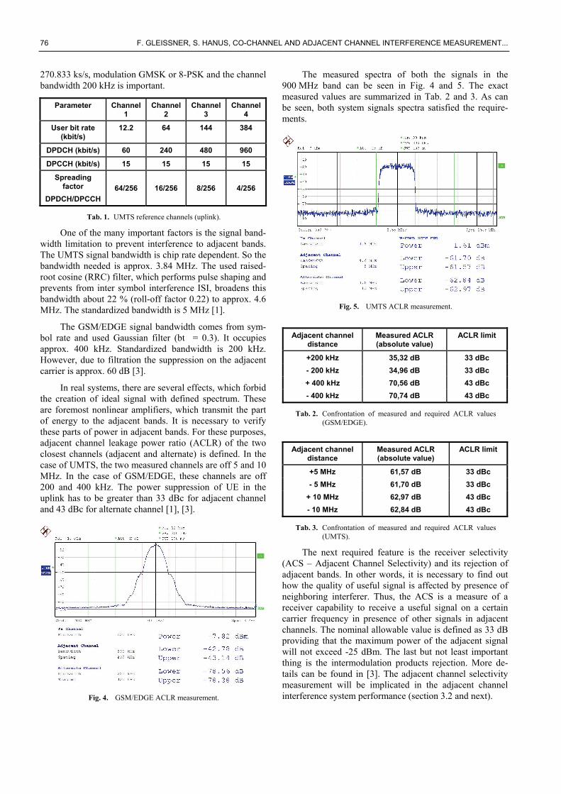
In real systems, there are several effects, which forbid the creation of ideal signal with defined spectrum. These are foremost nonlinear amplifiers, which transmit the part of energy to the adjacent bands. It is necessary to verify these parts of power in adjacent bands. For these purposes, adjacent channel leakage power ratio (ACLR) of the two closest channels (adjacent and alternate) is defined. In the case of UMTS, the two measured channels are off 5 and 10 MHz. In the case of GSM/EDGE, these channels are off 200 and 400 kHz. The power suppression of UE in the uplink has to be greater than 33 dBc for adjacent channel and 43 dBc for alternate channel [1], [3].
Fig. 4. GSM/EDGE ACLR measurement.
The measured spectra of both the signals in the 900 MHz band can be seen in Fig. 4 and 5. The exact measured values are summarized in Tab. 2 and 3. As can be seen, both system signals spectra satisfied the require-ments.
Fig. 5. UMTS ACLR measurement.
Adjacent channel
distance Measured ACLR (absolute value)
ACLR limit
+200 kHz 35,32 dB 33 dBc - 200 kHz 34,96 dB 33 dBc + 400 kHz 70,56 dB 43 dBc - 400 kHz 70,74 dB 43 dBc
Tab. 2. Confrontation of measured and required ACLR values (GSM/EDGE).
Adjacent channel
distance Measured ACLR (absolute value)
ACLR limit
+5 MHz 61,57 dB 33 dBc - 5 MHz 61,70 dB 33 dBc
+ 10 MHz 62,97 dB 43 dBc - 10 MHz 62,84 dB 43 dBc
Tab. 3. Confrontation of measured and required ACLR values (UMTS).
The next required feature is the receiver selectivity (ACS – Adjacent Channel Selectivity) and its rejection of adjacent bands. In other words, it is necessary to find out how the quality of useful signal is affected by presence of neighboring interferer. Thus, the ACS is a measure of a receiver capability to receive a useful signal on a certain carrier frequency in presence of other signals in adjacent channels. The nominal allowable value is defined as 33 dB providing that the maximum power of the adjacent signal will not exceed -25 dBm. The last but not least important thing is the intermodulation products rejection. More de-tails can be found in [3]. The adjacent channel selectivity measurement will be implicated in the adjacent channel interference system performance (section 3.2 and next).
RADIOENGINEERING, VOL. 17, NO. 3, SEPTEMBER 2008 77
3. Results The following sections provide both the measured and
simulated results. Section 3.1 verifies the minimum required values of CNR or Eb/N0 for reaching the nominal raw BER 10-3. Sections 3.2 and 3.3 provide performance of both the UMTS and GSM/EDGE systems in presence of adjacent interferers. Finally, section 3.4 provides coexis-tence measurements under operation in common radio band for frequency planning of the sandwich type (see section 1).
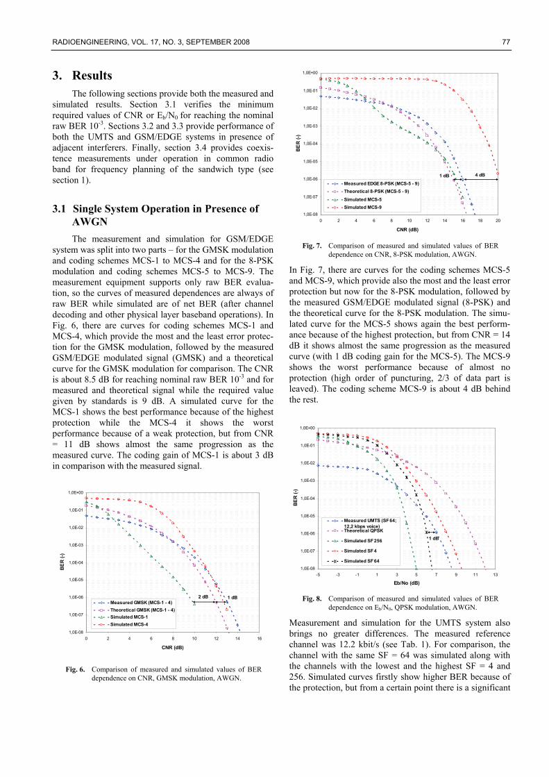
3.1 Single System Operation in Presence of AWGN The measurement and simulation for GSM/EDGE
system was split into two parts – for the GMSK modulation and coding schemes MCS-1 to MCS-4 and for the 8-PSK modulation and coding schemes MCS-5 to MCS-9. The measurement equipment supports only raw BER evalua-tion, so the curves of measured dependences are always of raw BER while simulated are of net BER (after channel decoding and other physical layer baseband operations). In Fig. 6, there are curves for coding schemes MCS-1 and MCS-4, which provide the most and the least error protec-tion for the GMSK modulation, followed by the measured GSM/EDGE modulated signal (GMSK) and a theoretical curve for the GMSK modulation for comparison. The CNR is about 8.5 dB for reaching nominal raw BER 10-3 and for measured and theoretical signal while the required value given by standards is 9 dB. A simulated curve for the MCS-1 shows the best performance because of the highest protection while the MCS-4 it shows the worst performance because of a weak protection, but from CNR = 11 dB shows almost the same progression as the measured curve. The coding gain of MCS-1 is about 3 dB in comparison with the measured signal.
1,0E-08
1,0E-07
1,0E-06
1,0E-05
1,0E-04
1,0E-03
1,0E-02
1,0E-01
1,0E+00
0 2 4 6 8 10 12 14 16
CNR (dB)
BER
(-)
Measured GMSK (MCS-1 - 4)Theoretical GMSK (MCS-1 - 4)Simulated MCS-1Simulated MCS-4
2 dB 1 dB
Fig. 6. Comparison of measured and simulated values of BER
dependence on CNR, GMSK modulation, AWGN.
1,0E-08
1,0E-07
1,0E-06
1,0E-05
1,0E-04
1,0E-03
1,0E-02
1,0E-01
1,0E+00
0 2 4 6 8 10 12 14 16 18 20
CNR (dB)
BER
(-)
Measured EDGE 8-PSK (MCS-5 - 9)Theoretical 8-PSK (MCS-5 - 9)
Simulated MCS-5Simulated MCS-9
4 dB1 dB
Fig. 7. Comparison of measured and simulated values of BER
dependence on CNR, 8-PSK modulation, AWGN.
In Fig. 7, there are curves for the coding schemes MCS-5 and MCS-9, which provide also the most and the least error protection but now for the 8-PSK modulation, followed by the measured GSM/EDGE modulated signal (8-PSK) and the theoretical curve for the 8-PSK modulation. The simu-lated curve for the MCS-5 shows again the best perform-ance because of the highest protection, but from CNR = 14 dB it shows almost the same progression as the measured curve (with 1 dB coding gain for the MCS-5). The MCS-9 shows the worst performance because of almost no protection (high order of puncturing, 2/3 of data part is leaved). The coding scheme MCS-9 is about 4 dB behind the rest.
1,0E-08
1,0E-07
1,0E-06
1,0E-05
1,0E-04
1,0E-03
1,0E-02
1,0E-01
1,0E+00
-5 -3 -1 1 3 5 7 9 11 13
Eb/No (dB)
BER
(-)
Measured UMTS (SF 64;12,2 kbps voice)Theoretical QPSK
Simulated SF 256
Simulated SF 4
Simulated SF 64
1 dB
Fig. 8. Comparison of measured and simulated values of BER
dependence on Eb/N0, QPSK modulation, AWGN.
Measurement and simulation for the UMTS system also brings no greater differences. The measured reference channel was 12.2 kbit/s (see Tab. 1). For comparison, the channel with the same SF = 64 was simulated along with the channels with the lowest and the highest SF = 4 and 256. Simulated curves firstly show higher BER because of the protection, but from a certain point there is a significant
78 F. GLEISSNER, S. HANUS, CO-CHANNEL AND ADJACENT CHANNEL INTERFERENCE MEASUREMENT...
gain. The required value of Eb/N0 given by standards for 12.2 kbit/s reference channel is 5 dB for reaching nominal raw BER 10-3. Both compared signals of SF = 64 meet this requirement.
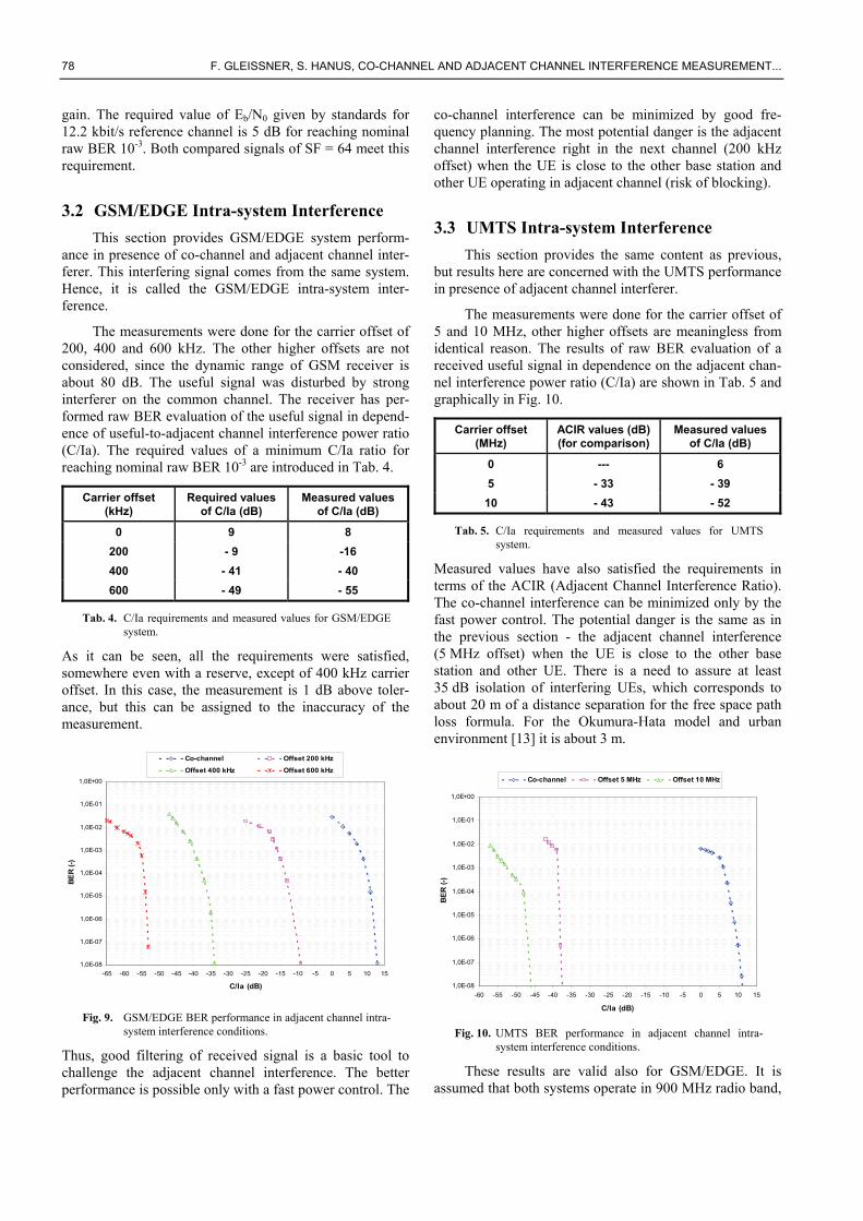
3.2 GSM/EDGE Intra-system Interference This section provides GSM/EDGE system perform-
ance in presence of co-channel and adjacent channel inter-ferer. This interfering signal comes from the same system. Hence, it is called the GSM/EDGE intra-system inter-ference.
The measurements were done for the carrier offset of 200, 400 and 600 kHz. The other higher offsets are not considered, since the dynamic range of GSM receiver is about 80 dB. The useful signal was disturbed by strong interferer on the common channel. The receiver has per-formed raw BER evaluation of the useful signal in depend-ence of useful-to-adjacent channel interference power ratio (C/Ia). The required values of a minimum C/Ia ratio for reaching nominal raw BER 10-3 are introduced in Tab. 4.
Carrier offset (kHz)
Required values of C/Ia (dB)
Measured values of C/Ia (dB)
0 9 8 200 - 9 -16 400 - 41 - 40 600 - 49 - 55
Tab. 4. C/Ia requirements and measured values for GSM/EDGE system.
As it can be seen, all the requirements were satisfied, somewhere even with a reserve, except of 400 kHz carrier offset. In this case, the measurement is 1 dB above toler-ance, but this can be assigned to the inaccuracy of the measurement.
1,0E-08
1,0E-07
1,0E-06
1,0E-05
1,0E-04
1,0E-03
1,0E-02
1,0E-01
1,0E+00
-65 -60 -55 -50 -45 -40 -35 -30 -25 -20 -15 -10 -5 0 5 10 15
C/Ia (dB)
BER
(-)
Co-channel Offset 200 kHz
Offset 400 kHz Offset 600 kHz
Fig. 9. GSM/EDGE BER performance in adjacent channel intra-
system interference conditions.
Thus, good filtering of received signal is a basic tool to challenge the adjacent channel interference. The better performance is possible only with a fast power control. The
co-channel interference can be minimized by good fre-quency planning. The most potential danger is the adjacent channel interference right in the next channel (200 kHz offset) when the UE is close to the other base station and other UE operating in adjacent channel (risk of blocking).
3.3 UMTS Intra-system Interference This section provides the same content as previous,
but results here are concerned with the UMTS performance in presence of adjacent channel interferer.
The measurements were done for the carrier offset of 5 and 10 MHz, other higher offsets are meaningless from identical reason. The results of raw BER evaluation of a received useful signal in dependence on the adjacent chan-nel interference power ratio (C/Ia) are shown in Tab. 5 and graphically in Fig. 10.
Carrier offset (MHz)
ACIR values (dB) (for comparison)
Measured values of C/Ia (dB)
0 --- 6 5 - 33 - 39
10 - 43 - 52
Tab. 5. C/Ia requirements and measured values for UMTS system.
Measured values have also satisfied the requirements in terms of the ACIR (Adjacent Channel Interference Ratio). The co-channel interference can be minimized only by the fast power control. The potential danger is the same as in the previous section - the adjacent channel interference (5 MHz offset) when the UE is close to the other base station and other UE. There is a need to assure at least 35 dB isolation of interfering UEs, which corresponds to about 20 m of a distance separation for the free space path loss formula. For the Okumura-Hata model and urban environment [13] it is about 3 m.
1,0E-08
1,0E-07
1,0E-06
1,0E-05
1,0E-04
1,0E-03
1,0E-02
1,0E-01
1,0E+00
-60 -55 -50 -45 -40 -35 -30 -25 -20 -15 -10 -5 0 5 10 15
C/Ia (dB)
BER
(-)
Co-channel Offset 5 MHz Offset 10 MHz
Fig. 10. UMTS BER performance in adjacent channel intra-
system interference conditions.
These results are valid also for GSM/EDGE. It is assumed that both systems operate in 900 MHz radio band,
RADIOENGINEERING, VOL. 17, NO. 3, SEPTEMBER 2008 79
height of base stations is approx. 25 m, height of UEs is approx 1.5 m.
3.4 Coexistence Investigation and Inter-system Interference The benefits of UMTS900 are all a result of the lower
carrier frequency. UMTS at 900 MHz will propagate fur-ther than its equivalent at 2100 MHz. Better propagation also means the interference will propagate better. The in-crease of interference due to better propagation conditions must be considered [4].
The measurement scenario was the following: both the useful GSM/EDGE and UMTS interfering signals were transmitted on the common channel. The power of signals with 1 dB step was set on the output of both transmitters. The receiver was matched to the useful GSM/EDGE signal and has performed the evaluation of BER in dependence on a power setting. The same measurement was done for the UMTS signal as useful and GSM/EDGE as interfering. The results achieved are presented inFig. 11 and 12.
Carrier offset (MHz)
UMTS useful GSM useful
Up to 2 Not sufficient Not sufficient 2.2 Not sufficient Not sufficient 2.4 Borderline Not sufficient 2.6 Enough Borderline
Tab. 6. Summary of an interference impact.
As it can be seen from both figures, there is a signifi-cant reduction of performance or in other words there is an increase of interference level if the carrier separation is up to 2.2 MHz.
1,0E-08
1,0E-07
1,0E-06
1,0E-05
1,0E-04
1,0E-03
1,0E-02
1,0E-01
1,0E+00
-50 -45 -40 -35 -30 -25 -20 -15 -10 -5 0 5 10
P(EDGE)/P(UMTS) (dB)
BER
(-)
Co-channel Offset 0.4 MHzOffset 0.8; 1.2; 1.6 MHz Offset 1.8 MHzOffset 2.0 MHz Offset 2.2 MHzOffset 2.4 MHz Offset 2.6 MHz
Fig. 11. GSM/EDGE performance in presence of interfering
UMTS signal, BER dependence on interfering signal power and carrier spacing.
In case of GSM/EDGE useful signal and 2.4 MHz carrier separation, there is a reserve of 25 dB to meet the nominal
raw BER 10-3. This value is not so high and can cause quality degradation. For 2.6 MHz carrier separation, there is a reserve of 35 dB. This value is sufficient for good quality communication (in terms of distance separation).
In case of UMTS useful signal and 2.4 MHz carrier separation, there is a reserve of 37 dB. This value is suffi-cient as was mentioned above. For 2.6 MHz, there is even 48 dB reserve. This value will neither limit the quality nor capacity of the system. The interference level will not be increased. As can be seen, the UMTS signal is more resis-tant than the GSM/EDGE signal.
1,0E-08
1,0E-07
1,0E-06
1,0E-05
1,0E-04
1,0E-03
1,0E-02
1,0E-01
1,0E+00
-55 -50 -45 -40 -35 -30 -25 -20 -15 -10 -5 0 5 10
P(UMTS)/P(EDGE) (dB)
BER
(-)
Co-channel Offset 0.4 MHzOffset 0.8; 1.2; 1.6 MHz Offset 2.0 MHzOffset 2.2 MHz Offset 2.4 MHzOffset 2.6 MHz
Fig. 12. UMTS performance in presence of interfering
GSM/EDGE signal, BER dependence on interfering signal power and carrier spacing.
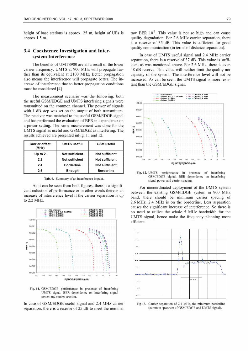
For uncoordinated deployment of the UMTS system between the existing GSM/EDGE system in 900 MHz band, there should be minimum carrier spacing of 2.6 MHz. 2.4 MHz is on the borderline. Less separation causes the significant increase of interference. So there is no need to utilize the whole 5 MHz bandwidth for the UMTS signal, hence make the frequency planning more efficient.
Fig 13. Carrier separation of 2.4 MHz, the minimum borderline
(common spectrum of GSM/EDGE and UMTS signal).
80 F. GLEISSNER, S. HANUS, CO-CHANNEL AND ADJACENT CHANNEL INTERFERENCE MEASUREMENT...
4. Conclusions This paper provides some measurement and simula-
tion results for the GSM/EDGE and the UMTS signal in presence of the adjacent channel interference.
Basic parameters of both systems and requirements for inter-working were presented as well as the simulation and measurement scenario.
The minimum CNR (Eb/N0) values to meet the nomi-nal BER 10-3 were verified on the AWGN channel. The fulfillment of the ACS and the ACLR was also verified in a particular measurement.
The curves of intra-system interference from sections 3.2 and 3.3 show potential risks especially in GSM/EDGE system for the 200 kHz adjacent channel interference. The isolation here is very poor, so the good frequency planning and power control is a crucial issue.
In the coexistence measurement, some important things were found out. Firstly, the carrier separation up to 2.2 MHz is never sufficient. Then, the carrier separation of 2.4 MHz is on the borderline, it may cause problems. The power control doesn’t need to be enough. Finally, the car-rier separation of 2.6 MHz is recommended as a reliable minimum, when the problems are excluded. The GSM/EDGE system is more vulnerable in presence of the adjacent wideband UMTS signal, while the UMTS system is more resistant in presence of the adjacent narrowband GSM/EDGE signal. The instruments to reduce these effects of the adjacent channel interference are high quality filters, transmitters with the minimal ACLR and the fast power control.
The further research will be focused on multiple UEs interference investigation, downlink measurements and getting more precise results as the technology will allow.
Acknowledgements The research described in the paper was financially
supported by the Czech Grant Agency under grant No. 102/ 08/H027, Advanced Methods, Structures and Compo-nents of Electronic Wireless Communication, under grant No. 102/07/1295, Mobile Network Models and their Parts, and by the Czech Ministry of Education under grant MSM 21630513, Electronic Communication Systems and New Generation Technologies (ELKOM).
References [1] KRUGER, R., MELLEIN, H. UMTS: Introduction and
Measurement. Rohde&Schwarz GmbH&Co. KG, Germany, 2004.
[2] LAIHO, J., WACKER, A., NOVOSAD, T. Radio Network Planning and Optimisation for UMTS. John Wiley & Sons Ltd, 2005. ISBN 0-470-01575-6.
[3] ETSI, Technical Specification 125 101 (3GPP TS 25.101), Universal Mobile Telecommunications System (UMTS); User Equipment (UE) Radio Transmission and Reception (FDD), v7.2.0.
[4] ISCO International Technology and Systems Group. Optimization of the Spectral Efficiency of 900 MHz Codeployments of UMTS and GSM. Technical brief, November 2007. ISCO International.
[5] HOLMA, H., TOSKALA, A. WCDMA for UMTS: Radio Access for Third Generation Mobile Communications. John Wiley & Sons Ltd, England, 2005. ISBN 0-470-87096-6.
[6] SEURRE, E., SAVELLI, P., PIETRI, P.-J. EDGE for Mobile Internet. Artech House Publishers, 2003. ISBN 1-58053-597-6.
[7] ETSI, Technical Specification 100 573 (3GPP TS 05.01), Digital Cellular Telecommunications System; Physical Layer on the Radio Path, v8.9.0.
[8] ETSI, EN 300 908 (GSM 05.02), Digital Cellular Telecommunications System; Multiplexing and Multiple Access on the Radio Path, v8.5.1.
[9] ETSI, Technical Specification 100 909 (3GPP TS 05.03), Digital Cellular Telecommunications System; Channel Coding, v8.9.0 (2005-01).
[10] 3GPP, Technical Specification 05.04, Digital Cellular Telecommunications System; Modulation, v8.3.0.
[11] 3GPP, Technical Specification 25.212, Multiplexing and Channel Coding (FDD), v5.4.0.
[12] COST 231, Final report. Digital Mobile Radio Towards Future Generation Systems. <http://www.lx.it.pt/cost231/final_report.htm>
[13] GLEISSNER, F., HANUS, S. The comparison of GSM-EDGE signal transmission over AWGN and Rayleigh fading channel. In Proceedings of the 18th International Conference Radioelektronika 2008. Praha, Czechoslovakia Section IEEE. p. 109 - 112. ISBN 978-1-4244-2087-2.
[14] GLEISSNER, F., RŮŽIČKA, Z., HANUS, S. UMTS - Impact of channel coding on BER. In Proceedings of the 15th International Electrotechnical and Computer Science Conference ERK 2007. 16(1), p. 136 - 139. ISSN 1581-4572.
About Authors... Filip GLEISSNER was born in Brno, Czech Republic, in 1981. He received the MSc degree in 2005 from the Brno University of Technology, Department of Radio Elec-tronics. At present, he is a PhD student at the Brno Univer-sity of Technology, Department of Radio Electronics, Fac-ulty of Electrical Engineering and Communication in Brno. He is concerned with wireless communications and their coexistence. His work is focused on GSM, GPRS, EDGE, UMTS and other wireless data transmission systems.
Stanislav HANUS was born in Brno, Czech Republic, in 1950. He received the Ing. (M.Sc.) and CSc. (Ph.D.) de-grees from the Brno University of Technology. He is Pro-fessor at the Department of Radio Electronics, Faculty of Electrical Engineering and Communication in Brno. His research is concentrated on Mobile Communications and Television Technology.