Embed Size (px)
Citation preview

A STUDY OF CO-CHANNEL AND ADJACENT-CHANNEL INTERFERENCE IMMUNITIES OF SUBSIDIARY COMMUNICATIONS AUTHORIZATION (SCA)
FM BROADCAST RECEIVERS
----------
Project TRB-99-3 Preliminary Report
December 1, 2000
Technical Research Branch Laboratory Division
Office of Engineering and Technology Federal Communications Commission
OET Report Prepared by: FCC/OET TRB-00-1 David L. Means

2
Project TRB-99-3 December 1, 2000
A STUDY OF CO-CHANNEL AND ADJACENT-CHANNEL INTERFERENCE IMMUNITIES OF SUBSIDIARY COMMUNICATIONS AUTHORIZATION (SCA)
FM BROADCAST RECEIVERS Executive Summary This preliminary report presents the results of a study intended to produce objective data on the interference performance of thirteen Subsidiary Communications Authorization (SCA) FM broadcast receivers used for reception of Radio Reading Service. This study was primarily intended to explore concerns raised in the record of the Commission’s proceeding In the Matter of Creation of Low Power Radio Service, MM Docket No. 99-25, regarding the potential impact on the Radio Reading Service of eliminating third adjacent channel interference protections for 10 watt and 100 Low Power FM (LPFM) stations. The study was conducted using a sample of fourteen FM broadcast SCA receivers provided by National Public Radio (NPR). Thirteen of these receivers were tested for adjacent-channel and co-channel interference performance; the remaining receiver was deemed not testable because of severe main channel bleedthrough problems. Because of the small sample size, the test results presented herein were not extrapolated to the general receiver population. The median ratios of interfering signal-to-desired signal, i.e., undesired-to-desired (U/D) ratios, for 1% increased impairment found for the sample receivers on third and fourth adjacent channels were 36.6 dB and 37.9 dB, respectively. Both of these values fell short of the Commission’s 40 dB U/D criteria for third adjacent FM channels by a few dB. Thus, some receivers in this sample might not adequately reject the signal of a LPFM station operating on a third adjacent channel when used in close proximity to that station. In addition, some receivers might not be able to reject the signals of existing full power stations operating on fourth adjacent channels consistent with the Commission’s longstanding FM separation requirements. In fact, several of the tested receivers were more susceptible to signals on fourth adjacent channels than to signals on third adjacent channels. It appears, however, that most potential receiver performance problems could be resolved on a case-by-case basis by providing the affected listener with a directional external antenna or by selecting an SCA receiver with interference rejection characteristics appropriate to the case at hand. Providing outboard filters may also solve most receiver performance problems, but this approach is not likely to be cost-effective. Interference from the main audio program channel of the station carrying the SCA, i.e., bleedthrough, was audible in eight of the receivers, even under unimpaired conditions. In two of these receivers, the audible level of the main channel bleedthrough worsened with the level of the interference impairment, and was indeed the principle audible manifestation of the interference. In receivers such as these two, the increased bleedthrough can mask the perception of interference or even render it undetectable as such. Several of the receivers tested also exhibited gross asymmetry in their selectivity characteristics, leading to our conclusion that their adjacent channel interference performance is compromised by misalignment. The Receiver Sample The 14 SCA receivers provided by NPR were solicited from member stations who transmit radio reading services. Although the manufacturers of two of the receivers are not known with certainty, at least nine different manufacturers have models represented in the sample. Four of the receivers were manufactured by McMartin; however, these four all have slightly different model designations. All the receivers in the sample except one are small tabletop or portable receivers, designed for personal

3
residential use, with an integral whip antenna and loudspeaker. The single exception is a receiver designed for mounting in an equipment rack in an institutional or commercial installation. All except one were fixed-tuned to a particular host station frequency and SCA frequency. The single exception was a receiver which had two modes of operation: one which allowed operation only on a single parent station and SCA frequency, and another mode in which the entire FM broadcast band could be tuned for main-channel programming only. Twelve of the receivers had provisions for some form of external antenna input, typically a Type F connector or terminal screws. One receiver had an unorthodox external antenna connection consisting of a pair of unlabeled pressure-fit lugs. The only information provided with the receivers regarding appropriate technical parameters for testing was the host station carrier frequency and the corresponding SCA frequency. Attempts were made to obtain additional information on other parameters (such as de-emphasis characteristics, maximum modulating frequency and peak deviation) from the station contacts provided by NPR, but complete information was not available for most of the receivers. Of necessity, default test values were used for maximum modulating frequency and peak deviation, and appropriate pre-emphasis/de-emphasis for each receiver was determined experimentally. Both receiver characterization and interference testing were attempted on all 14 receivers, although one receiver proved untestable for interference immunities because of severe main-channel bleedthrough into the demodulated SCA audio. Characterization Tests Because the interference measurements essentially constituted a test of the selectivity of the receivers, and because the performance of the receivers’ audio sections was not germane to the issues at hand, the only characterization test deemed necessary was quieting sensitivity. This characteristic is determined by the RF input signal power necessary to produce 50 dB of quieting in the audio output. For receivers that were incapable of achieving 50 dB quieting, the maximum quieting achievable and the quieting level at –55 dBm RF input were measured and recorded. To the extent they are applicable to SCA receivers, the procedures outlined in IEEE Standard 185-1975 were followed. As noted in the data tables, for receivers without external antenna inputs of known impedance, the RF input values stated are test bed power output values only. Interference Testing Methodology The appropriate methodology for quantifying the manifestation of interference in the audio output of radio broadcast receivers has been a matter of some controversy in the LPFM rule making proceeding. FCC Laboratory engineering staff maintains that interference is best quantified in terms of relative degradation of the audio output signal as compared to the unimpaired condition, in contrast to methods which target an absolute signal quality goal expressed in terms of Signal-plus-Noise to Noise [(S+N)/N]. Further, (S+N)/N methods require that the modulating signal be removed from the desired signal in order to perform the measurement, eliminating the possibility of capturing any audio intermodulation interference effects which might be present. For these reasons, the methodology chosen for these tests is the measurement of the undesired-to-desired (U/D) RF signal ratios necessary to produce degradation of the unimpaired baseline Total Harmonic Distortion plus Noise (THD+N) of the audio output by an additional 1% and 3%. This method captures all interference energy, regardless of how it is manifested, but the noise term N is typically dominant.

4
Interference Testing Procedure The interconnection of the test equipment and the equipment under test is diagrammed in Figure 1.
Circuit Research LaboratoriesSG-800A
Stereo Generator
HP 8o57APrecision Noise
Generator
HP 8642BSignal Generator
Circuit Research LaboratoriesSG-800A
Stereo Generator
Audio PrecisionSystem One
SYS322AAudio Analyzer
HP 8642BSignal Generator
DBX 166ACompressor/Limiter
Orban 8455A Opt imod(filter only)
HP 8664A Signal Generator
Rane GE-14Graphic Equalizer
MiniCircuitsZFSC-2-1W
Splitter/Combiner
HP 11694A50/75 Ohm Xfmr
Receiver UnderTest
Tektronix 475Oscilloscope
HP 8901Modulation Analyzer
HP 8568ASpectrum Analyzer
C DPlayer
Pink Noise
Main Channel In
Stereo Baseband Stereo Baseband
Modulated Carrier Modulated Carrier
1 kHz Tone
SCA In Main In
Audio Out
Baseband0 - 100 kHz
UNDESIRED SIGNAL DESIRED SIGNAL
Figure 1 Equipment Configuration
The desired signal’s carrier was generated on the parent station’s nominal frequency for each receiver under test using a Hewlett Packard 8642B signal generator. This carrier was modulated by the composite baseband output of a CRL SG-800A stereo generator. To exercise the main stereo channel of the desired signal, “easy listening” musical programming was fed to the main inputs of the stereo generator from a CD player. The programming used was Natalie Cole: Take a Look, Track 1: “I Wish You Love.” The SCA input of the stereo generator was fed either a 67 kHz or 92 kHz modulated subcarrier, as appropriate, generated by FM modulating the Hewlett Packard 8664A signal generator with a 1 kHz tone provided by the Audio Precision System One audio analyzer. Deviation produced by the 1 kHz tone was set at +/- 6 kHz. Appropriate pre-emphasis on the SCA baseband was applied using the Rane GE-14 graphic equalizer. The appropriate pre-emphasis for each receiver was determined by substituting a pink noise signal for the 1 kHz tone as the modulating signal input to the HP8664A signal generator, and then adjusting the equalizer settings to produce a flat audio output response from the receiver under test with the tone control, if provided, set in the nominally flat position. Flatness of the audio response was measured using an Audio Control SA-3050A real time spectrum analyzer. No

5
attempt was made to boost the audio response below 100 Hz or above 5 kHz, and all equalizer bands above 6.3 kHz were set for maximum attenuation. The stereo generator and HP 8642B signal generator were adjusted to provide 105% total modulation of the desired signal carrier, with the stereo pilot and SCA subcarrier injection levels set at 10% each. Main channel modulation was set at a relatively low level, with the programming used illuminating the 100% modulation indicator only on occasional peaks. Similarly, the modulated carrier for the undesired signal was generated by another HP 8642B signal generator, with the composite stereo baseband input provided by another CRL SG-800A stereo generator. The modulating signal was pink noise provided by a Hewlett Packard 8057A precision noise generator. The pink noise was band-limited using the filter section of the Orban 8455A Optimod processor, and compressed and limited using the DBX 166A compressor/limiter to simulate heavily processed program material. In order to provide as accurate a simulation as possible of real-world interference from a heavily modulated station with highly processed rock music programming, such a station was selected from the local off-the-air FM broadcast spectrum, and the undesired signal’s modulation levels, compression, and limiting were adjusted to accurately duplicate the off-the-air station’s spectral envelope. Co-channel and adjacent channel interference tests on all upper and lower adjacent channels up to the fourth adjacent channel were conducted on each receiver in the sample by combining the desired and undesired modulated carriers in a Minicircuits ZFSC-2-1 splitter/combiner, and providing the combined signal to the RF input of the receiver under test, using a matching transformer if necessary. In all cases, the desired signal level provided to the receiver was –55 dBm, which is approximately the signal level delivered to a receiver by a dipole antenna located at an FM broadcast station’s 60 dBu protected contour. Impairment was quantified by measuring the increase in THD+N on the 1 kHz demodulated audio tone produced by introduction of the undesired signal, using the Audio Precision System One audio analyzer. A baseline value for THD+N was first determined for each receiver with no undesired signal or main channel modulation on the desired signal present. The main channel modulation was then turned on, and the level of the undesired signal was slowly increased until a level was reached where the measured THD+N exceeded the baseline value by one percentage point on peaks of frequent recurrence. The undesired to desired signal ratio (U/D) was recorded at that point. The undesired signal was then further increased until the measured THD+N exceeded the baseline value by 3%, and the U/D was again recorded. This process was repeated for each co-channel and adjacent-channel situation for each receiver, and the results tabulated and graphed. To provide an audio record for subjective evaluation using program material, CD recordings of the B-52s “Love Shack” and an a cappella vocal by Suzanne Vega were substituted for the undesired and desired (SCA) signal modulations, respectively. These recordings were chosen to represent a potentially worst-case interferer as well as affected program material on which the presence of interference would be easily audible. For each receiver, a 60-second digital recording was made of the unimpaired audio, the audio impaired at the U/D ratio which produced a 1% increase in THD+N, and the audio impaired at the U/D ratio which produced a 3% increase in THD+N. These recordings were made for the upper third adjacent channel interference situation only. An index to these recordings is presented in Appendix C. Reasonable precautions were exercised throughout the data gathering effort to ensure against the incursion of unwanted ambient signals and testing artifacts. Measurements were conducted inside a shielded room, and ferrites were placed on each end of the cable connecting the signal combiner to the antenna input terminals of the receiver under test. 6 dB pads were placed on the outputs of the desired

6
and undesired carrier signal generators to reduce interaction. An isolation transformer was used on the power mains for the receivers under test. Audio output levels from the receivers were adjusted to minimize distortion and avoid overload in the receivers’ audio amplifiers. Observations on the Data Because of the relatively small test sample (13 receivers actually tested), caution is urged in extending conclusions from the data to the general population of SCA receivers. The data for all the receivers tested is summarized in a table in Appendix A in the form of median values for the U/D ratio necessary to produce each degradation level for each of the interference situations. For the adjacent-channel situations, these values are the medians of the combined upper and lower adjacent-channel measured values. It should be noted that for all table entries derived from an even number of measured values, the table entry represents the average of the two median measured values. The measured data for each individual receiver is tabulated and graphed in Appendix B. The tabulated data and graphs for Receiver B show measured U/D values of 65.5 dB for the upper third adjacent channel at 1% additional impairment and for both 1% and 3% additional impairment on the fourth adjacent channel. It should be noted that the actual values probably exceed 65.5 dB. The 65.5 dB value represents the upper limit of the capability of the test bed to generate the undesired signal. Conclusions Due to the small sample size, we are not extrapolating the test results to the general receiver population. However, some observations may be made for the sample at hand. Section 73.215 of the Commission’s rules provides that the predicted field strength of a potentially interfering station can be no more than 40 dB stronger than the protected field strength along a station’s protected contour. This protection was eliminated for the third adjacent channel situation for LPFM stations authorized under the R&O in MM Docket 99-25. Noting that the median U/D for 1% increased impairment is 36.6 dB for the third adjacent channel, one may reasonably conclude that most of the receivers in this sample could experience some interference when used in close proximity to an LPFM station that is operating on the third adjacent channel. Only three of the receivers tested exceeded 40 dB U/D for a 1% increase in THD+N on both the upper and lower third adjacent channel. While the median U/D for all fourth adjacent channel interference situations (37.9 dB) exceeded the median U/D for all third adjacent channel situations (36.6 dB), not all receivers performed better at the fourth adjacent channel than the third. Six of the receivers were less capable of rejecting interference at the fourth adjacent channel than the third on either the upper or lower adjacent channel situation or both. Given that SCA receivers do exist that exhibit adequate third and fourth adjacent channel interference performance, and that many of the receivers fell short of the 40 dB U/D criterion for third adjacent by only a few decibels, it appears possible to resolve most interference problems on a case-by-case basis by providing the affected listener with a directional external antenna or by selecting an SCA receiver with interference rejection characteristics appropriate to the case at hand. Providing outboard filters may also solve most interference problems, but this approach is not likely to be cost-effective as the cost of commercially available filters providing adequate performance approaches the cost of the typical receiver.

7
In listening to the audio output of the receivers during the testing, we noted that bleedthrough of the main channel audio signal was audible in eight of the receivers, even under unimpaired conditions. The bleedthrough was so severe in one case that the THD+N introduced by this phenomenon exceeded a 3% increase over the baseline value, rendering the receiver untestable. In two of these receivers, the audible level of the main channel bleedthrough worsened with the level of the interference impairment, and was indeed the principle audible manifestation of the interference. For these two receivers, such bleedthrough can mask the perception of interference or even render it undetectable as such. While this bleedthrough of audio content from the main channel was common in both impaired and unimpaired circumstances, intelligible crosstalk from the interfering signal was not apparent. In some of the recordings, the increased noise induced in the desired signal’s audio exhibited a rhythmic pattern that synchronized with the beat of the undesired signal’s program music. This is to be expected, as the extent of sideband energy distribution in the undesired signal varies in synchronization with musical programming. To verify our assumption that noise is indeed the dominant component in measured increases in THD+N due to interference, we conducted Fast Fourier Transform (FFT) analysis of digital recordings from several of the receivers under unimpaired, 1% increased impairment, and 3% increased impairment conditions. This analysis showed relatively little change in the levels of individual harmonic products, but a relatively large change in the noise floor with increasing impairment, confirming our assumptions. For optimum adjacent channel interference immunity in receivers in general, it is essential that any RF and IF filtering incorporated in the design be aligned symmetrically about the tuned frequency of the receiver. While several of the receivers displayed the expected symmetry in the graphs of adjacent channel selectivity, others show gross asymmetry. One could conclude that these receivers were either improperly aligned at the factory, misaligned during servicing, or had simply drifted out of proper alignment due to aging of components. Regardless of the cause, such misalignment adversely affects the interference rejection capabilities of the receiver when compared with the intentions of the designer.
8
APPENDIX A
DATA SUMMARY

9
Medians:
All Co-Channel All 1st Adjacent All 2nd Adjacent All 3rd Adjacent All 4th AdjacentU/D for 1% THD+N Increase (dB) -17.5 -1.25 27.4 36.6 37.9U/D for 3% THD+N Increase (dB) -14.1 0.05 28.55 37.9 40.35
APPENDIX A -- DATA SUMMARY

10
APPENDIX B
INDIVIDUAL RECEIVER DATA

11
Parent Frequency: 94.1 MHz
SCA Frequency: 67 kHzBaseline THD+N: 0.97%RF Input @ 50dB Quieting: Not Achievable
Max. Quieting: 44.5 dB @ 10.5 dBmQuieting @ -55 dBm: 44.5 dB
Lower 4th Lower 3rd Lower 2nd Lower 1st Co-Channel Upper 1st Upper 2nd Upper 3rd Upper 4thU/D for 1% THD+N Increase (dB)37.8 33.8 26.6 5.3 -14.1 0.8 27.9 36 37.3U/D for 3% THD+N Increase (dB)38.9 35.5 28.1 5.7 -14.1 1.5 28.1 37.1 38.3
Receiver A: SMC NR-1
Receiver A
-20
-10
0
10
20
30
40
50
U/D
(d
B) U/D for 1% THD+N
Increase (dB)
U/D for 3% THD+NIncrease (dB)

12
Parent Frequency: 94.1 MHzSCA Frequency: 67 kHzBaseline THD+N: 6.94% (crossover distortion and 120Hz hum visible on waveform)RF Input @ 50dB Quieting: Not AchievableMax. Quieting: 34.7 dB @ 10.5 dBmQuieting @ -55 dBm: 34.4 dBComment: 65.5 dB U/D is the limit of capability of the test bed; actual values on 3rd and 4th adjacent exceed 65.5 dB.
Lower 4th Lower 3rd Lower 2nd Lower 1st Co-Channel Upper 1st Upper 2nd Upper 3rd Upper 4thU/D for 1% THD+N Increase (dB)65.5 62.9 43.7 -2.3 -17.6 -0.8 41.5 61.5 65.5U/D for 3% THD+N Increase (dB)65.5 65.5 46.4 2.3 -13.1 3.5 44.8 65.3 65.5
Receiver B: Target FTJ-100
Receiver B
-30
-20
-10
0
1 0
2 0
3 0
4 0
5 0
6 0
7 0
U/D
(d
B)
U/D for 1% THD+NIncrease (dB)
U/D for 3% THD+NIncrease (dB)
13
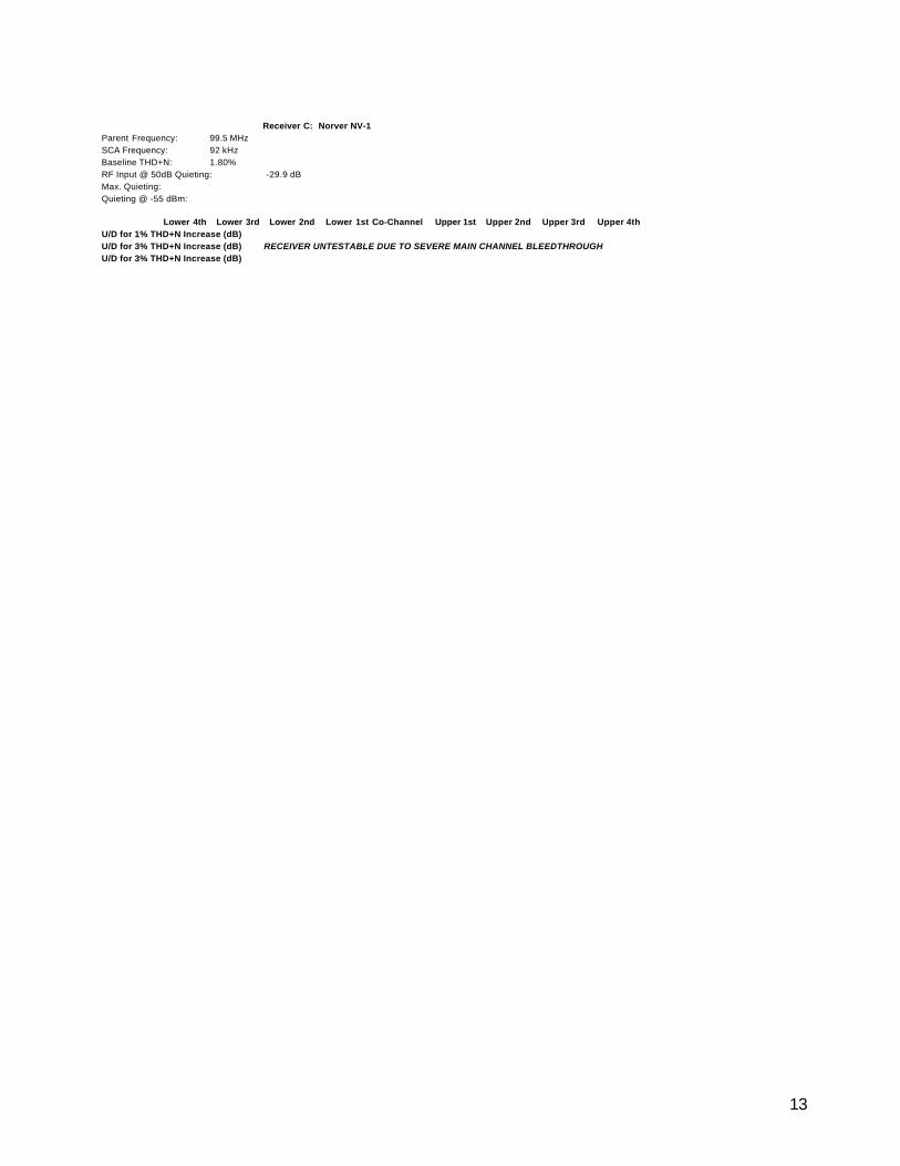
Parent Frequency: 99.5 MHzSCA Frequency: 92 kHzBaseline THD+N: 1.80%RF Input @ 50dB Quieting: -29.9 dBMax. Quieting:Quieting @ -55 dBm:
Lower 4th Lower 3rd Lower 2nd Lower 1st Co-Channel Upper 1st Upper 2nd Upper 3rd Upper 4thU/D for 1% THD+N Increase (dB)U/D for 3% THD+N Increase (dB) RECEIVER UNTESTABLE DUE TO SEVERE MAIN CHANNEL BLEEDTHROUGHU/D for 3% THD+N Increase (dB)
Receiver C: Norver NV-1

14
Parent Frequency: 101.9 MHzSCA Frequency: 67 kHzBaseline THD+N: 2.33%RF Input @ 50dB Quieting: -85.9 dBmMax. Quieting:Quieting @ -55 dBm:
Lower 4th Lower 3rd Lower 2nd Lower 1st Co-Channel Upper 1st Upper 2nd Upper 3rd Upper 4thU/D for 1% THD+N Increase (dB)41.7 39.4 31.3 4.7 -14.4 -0.2 21.7 36.2 32.4U/D for 3% THD+N Increase (dB)41.7 39.4 32 5 -8.8 0 21.9 36.9 35.7
Receiver D: ComPol SCA-7M
Receiver D
-20
-10
0
10
20
30
40
50
U/D
(d
B)
U/D for 1% THD+NIncrease (dB)
U/D for 3% THD+NIncrease (dB)

15
Parent Frequency: 91.5 MHzSCA Frequency: 92 kHzBaseline THD+N: 2.81%RF Input @ 50dB Quieting: -57.1 dBm
Max. Quieting:Quieting @ -55 dBm:
Lower 4th Lower 3rd Lower 2nd Lower 1st Co-Channel Upper 1st Upper 2nd Upper 3rd Upper 4thU/D for 1% THD+N Increase (dB)41.9 42.9 26.9 -2.5 -12.1 -2.7 19.3 34.4 35.4U/D for 3% THD+N Increase (dB)45.2 44.3 29 -0.2 -11 -0.7 19.6 35.6 35.9
Receiver E: ComPol SCA-BL
Receiver E
-20
-10
0
10
20
30
40
50
U/D
(d
B)
U/D for 1% THD+NIncrease (dB)
U/D for 3% THD+NIncrease (dB)

16
Parent Frequency: 91.5 MHzSCA Frequency: 67 kHzBaseline THD+N: 0.79%RF Input @ 50dB Quieting: -62.6 dBmMax. Quieting:Quieting @ -55 dBm:Comment: Audio bleedthrough from main channel under all conditions.
Lower 4th Lower 3rd Lower 2nd Lower 1st Co-Channel Upper 1st Upper 2nd Upper 3rd Upper 4thU/D for 1% THD+N Increase (dB)19.6 15.8 10 -1.6 -22.4 -11.1 25.8 23.4 24.1U/D for 3% THD+N Increase (dB)20.3 16.2 10.7 -1.1 -20.5 -9.8 26.1 25.6 24.9
Receiver F: McMartin TR-E5B
Receiver F
-30
-20
-10
0
10
20
30
U/D
(d
B)
U/D for 1% THD+NIncrease (dB)
U/D for 3% THD+NIncrease (dB)

17
Parent Frequency: 91.3 MHzSCA Frequency: 92 kHzBaseline THD+N: 2.87%RF Input @ 50dB Quieting: Not AchievableMax. Quieting: 42.0 dB @ +10.5 dBmQuieting @ -55 dBm: 40.9 dBComment: Audio bleedthrough from main channel under all conditions.
Lower 4th Lower 3rd Lower 2nd Lower 1st Co-Channel Upper 1st Upper 2nd Upper 3rd Upper 4thU/D for 1% THD+N Increase (dB)30.5 37 19.4 -5.9 -11.9 -1.6 24.4 45.8 42.8U/D for 3% THD+N Increase (dB)31.1 38.4 19.9 -2.4 -11.3 -0.8 25.6 47.1 50.8
Receiver G: McMartin TR-E5C
Receiver G
-20
-10
0
10
20
30
40
50
60
U/D
(d
B) U/D for 1% THD+N
Increase (dB)
U/D for 3% THD+NIncrease (dB)

18
Parent Frequency: 90.1 MHzSCA Frequency: 67 kHzBaseline THD+N: 2.19%RF Input @ 50dB Quieting: Not AchievableMax. Quieting: 45.9 dB @ +10.5 dBmQuieting @ -55 dBm: 45.7 dBComment: No external antenna input of known impedance; all absolute levels are signal generator output levels only.
Receiver identified by NPR as Compol SCA-BL; however, has no mfr. markings and does not resemble other ComPol SCA-BL in sample.
Lower 4th Lower 3rd Lower 2nd Lower 1st Co-Channel Upper 1st Upper 2nd Upper 3rd Upper 4thU/D for 1% THD+N Increase (dB)25.9 27.1 35.8 2.4 -14.5 3.6 38.3 24.8 25.9U/D for 3% THD+N Increase (dB)23.4 32.9 36.5 2.9 -10.1 4.1 39.9 25.3 26.6
Receiver H: Unknown (ComPol SCA-BL?)
Receiver H
-20
-10
0
10
20
30
40
50
U/D
(d
B)
U/D for 1% THD+NIncrease (dB)
U/D for 3% THD+NIncrease (dB)

19
Parent Frequency: 91.3 MHzSCA Frequency: 67 kHzBaseline THD+N: 1.69%RF Input @ 50dB Quieting: -58.4 dBmMax. Quieting:Quieting @ -55 dBm:Comment: No external antenna input of known impedance; all absolute levels are signal generator output levels only.
Lower 4th Lower 3rd Lower 2nd Lower 1st Co-Channel Upper 1st Upper 2nd Upper 3rd Upper 4thU/D for 1% THD+N Increase (dB)28.5 36.2 23.6 -4.8 -17.5 -8.4 20.2 42.6 38U/D for 3% THD+N Increase (dB)29.1 37.4 23.7 -1.2 -17 -4.3 20.5 43.5 40
Receiver I: Unknown (Chinese made)
Receiver I
-30
-20
-10
0
10
20
30
40
50
U/D
(dB
)
U/D for 1% THD+NIncrease (dB)
U/D for 3% THD+NIncrease (dB)

20
Parent Frequency: 90.7 MHzSCA Frequency: 67 kHzBaseline THD+N: 1.51%RF Input @ 50dB Quieting: -50.7 dBmMax. Quieting:Quieting @ -55 dBm: 47.2 dBmComment: Audio bleedthrough from main channel under all conditions.
Lower 4th Lower 3rd Lower 2nd Lower 1st Co-Channel Upper 1st Upper 2nd Upper 3rd Upper 4thU/D for 1% THD+N Increase (dB)31.6 33.3 48.4 2.7 -17.9 -0.9 38.3 38.9 37U/D for 3% THD+N Increase (dB)33 35.8 52.3 4.2 -14.5 0.2 38.9 40.7 37.9
Receiver J: Johnson DTR-6
Receiver J
-30
-20
-10
0
10
20
30
40
50
60
U/D
(dB
)
U/D for 1% THD+NIncrease (dB)
U/D for 3% THD+NIncrease (dB)

21
Parent Frequency: 90.7 MHzSCA Frequency: 67 kHzBaseline THD+N: 5.50% (audible power supply buzz/hum)RF Input @ 50dB Quieting: Not AchievableMax. Quieting: 34.4 dB @ +10.5 dBmQuieting @ -55 dBm: 34.4 dBComment: Audio bleedthrough from main channel under all conditions.
Lower 4th Lower 3rd Lower 2nd Lower 1st Co-Channel Upper 1st Upper 2nd Upper 3rd Upper 4thU/D for 1% THD+N Increase (dB)40 34.8 35.6 -5.3 -20.2 2.9 40.2 36.2 33.5U/D for 3% THD+N Increase (dB)40.7 35.5 36.1 -5 -16.4 5.2 42.7 37 42.8
Receiver K: Erko R-100
Receiver K
-30
-20
-10
0
10
20
30
40
50
U/D
(dB
)
U/D for 1% THD+NIncrease (dB)
U/D for 3% THD+NIncrease (dB)

22
Parent Frequency: 90.7 MHzSCA Frequency: 67 kHzBaseline THD+N: 2.32%RF Input @ 50dB Quieting: Not AchievableMax. Quieting: 42.7 dB @ +10.5 dBmQuieting @ -55 dBm: 42.3 dBComment: Audio bleedthrough from main channel under all conditions; increases with interference.
Lower 4th Lower 3rd Lower 2nd Lower 1st Co-Channel Upper 1st Upper 2nd Upper 3rd Upper 4thU/D for 1% THD+N Increase (dB)46.7 40.9 22.8 -0.4 -18.9 -0.9 25.5 40.7 44U/D for 3% THD+N Increase (dB)47 41.3 22.5 1 -18.6 0.1 25.9 41 44.3
Receiver L: McMartin TR-E6C
Receiver L
-30
-20
-10
0
10
20
30
40
50
60
U/D
(dB
)
U/D for 1% THD+NIncrease (dB)
U/D for 3% THD+NIncrease (dB)

23
Parent Frequency: 90.7 MHzSCA Frequency: 67 kHzBaseline THD+N: 0.84%RF Input @ 50dB Quieting: -57.3 dBmMax. Quieting:Quieting @ -55 dBm:Comment: Audio bleedthrough from main channel under all conditions; increases with interference.
Lower 4th Lower 3rd Lower 2nd Lower 1st Co-Channel Upper 1st Upper 2nd Upper 3rd Upper 4thU/D for 1% THD+N Increase (dB)51 42.1 32.5 8.6 -22.4 -15.8 -4 26.9 38.4U/D for 3% THD+N Increase (dB)51.2 42.4 33.1 14.2 -18.2 -14.6 -3 27.4 42.2
Receiver M: McMartin TR-E6A
Receiver M
-30
-20
-10
0
10
20
30
40
50
60
U/D
(dB
)
U/D for 1% THD+NIncrease (dB)
U/D for 3% THD+NIncrease (dB)

24
Parent Frequency: 91.5 MHzSCA Frequency: 92 kHzBaseline THD+N: 2.67%RF Input @ 50dB Quieting: Not AchievableMax. Quieting: 47.7 dB @ +10.5 dBmQuieting @ -55 dBm: 37.4 dBComment: No external antenna input of known impedance; all absolute levels are signal generator output levels only.
Lower 4th Lower 3rd Lower 2nd Lower 1st Co-Channel Upper 1st Upper 2nd Upper 3rd Upper 4thU/D for 1% THD+N Increase (dB)55.1 49.3 28.8 -2.3 -10.6 -3.3 31 44.9 54.8U/D for 3% THD+N Increase (dB)55.5 49.7 29.6 -1.4 -10.4 -0.3 31.7 45.4 55.9
Receiver N: Uniband RF-42
Receiver N
-20
-10
0
10
20
30
40
50
60
U/D
(dB
)
U/D for 1% THD+NIncrease (dB)
U/D for 3% THD+NIncrease (dB)

25
APPENDIX C
AUDIO RECORDING LOG

26
APPENDIX C – AUDIO RECORDING LOG All tracks are recordings of the demodulated audio of each receiver’s SCA channel, with impairment, when present, on the upper third adjacent channel. All tracks are 60 seconds long. Desired Channel Program: Suzanne Vega a cappella on SCA; Natalie Cole “I Wish You
Love” on main channel Undesired Channel Program: The B-52s “Love Shack” TRACK TITLE RECEIVER IMPAIRMENT U/D (dB) 1 AU A Unimpaired -- 2 A1% A 1% THD+N Increase 36.0 3 A3% A 3% THD+N Increase 37.1 4 BU B Unimpaired -- 5 B1% B 1% THD+N Increase 61.5 6 B3% B 3% THD+N Increase 65.3 7 DU D Unimpaired -- 8 D1% D 1% THD+N Increase 36.2 9 D3% D 3% THD+N Increase 36.9 10 EU E Unimpaired -- 11 E1% E 1% THD+N Increase 34.4 12 E3% E 3% THD+N Increase 35.6 13 FU F Unimpaired -- 14 F1% F 1% THD+N Increase 23.4 15 F3% F 3% THD+N Increase 25.6 16 GU G Unimpaired -- 17 G1% G 1% THD+N Increase 45.8 18 G3% G 3% THD+N Increase 47.1 19 HU H Unimpaired -- 20 H1% H 1% THD+N Increase 24.8 21 H3% H 3% THD+N Increase 25.3 22 IU I Unimpaired -- 23 I1% I 1% THD+N Increase 42.6 24 I3% I 3% THD+N Increase 43.5 25 JU J Unimpaired -- 26 J1% J 1% THD+N Increase 38.9 27 J3% J 3% THD+N Increase 40.7

27
28 KU K Unimpaired -- 29 K1% K 1% THD+N Increase 36.2 30 K3% K 3% THD+N Increase 37.0 31 LU L Unimpaired -- 32 L1% L 1% THD+N Increase 40.7 33 L3% L 3% THD+N Increase 41.0 34 MU M Unimpaired -- 35 M1% M 1% THD+N Increase 26.9 36 M35 M 3% THD+N Increase 27.4 37 NU N Unimpaired -- 38 N1% N 1% THD+N Increase 44.9 39 N3% N 3% THD+N Increase 45.4