Embed Size (px)
Citation preview
www.sensurity.com
Feb 2016
Reducing False Alarms in Perimeter Intrusion Detection Systems (PIDS):
White Paper
Executive Summary
All Perimeter Intrusion Detection Systems are susceptible to false
alarms and it is critical that all PID manufacturers continuously strive to
lower these false alarm rates. Microwave PID Systems have a low false
alarm rate in comparison to other systems, however to make microwave
a suitable PID system for a wide range of sites (over water, very close to
fences, areas of dense foliage etc.) it is imperative to continuously strive
to reduce false alarm rates.
Microwave PIDS work by analysing changes in the received signal
between a transmitter and a receiver. From a historical point of view
they have suffered from an inability to discriminate between a human
target and false alarm events from animals, weather and the movement
of trees and foliage. False perimeter alarms create considerable
additional effort and headache for operators to manage. Even a very low
Nuisance Alarm Rate (NAR) has a severe effect on Perimeter security
system performance.
This report provides an analysis of how to reduce false alarm rates in Microwave PID systems. The three
attributes of a PID system (below) are investigated to analyse their potential to decrease the false alarm rates
caused by the three sources mentioned above.
• Operating Frequency
• Antenna
• and Digital Signal Processing (DSP) of the data.
This report finds that by combining adjustments in the operating frequency, antenna design and DSP
methods, a significant effect can be made on the false alarm rates currently facing microwave PIDS; making it
an attractive choice for perimeter security application.
Problem Statement
Microwave PIDS are susceptible to reduction in performance and increased system costs due to false alarm
rates. False alarms rates in any alarm system reduces the effectiveness of that system and creates additional
costs for operators. Therefore reducing false alarm rates of a system whilst not compromising system
performance, is a key factor for PIDS manufacturers. False alarms in microwave PIDS are generally caused by
three different categories:
• Weather
• Foliage
• Animals.
The way these three categories affect the system varies considerably and therefore the three categories must
be dealt with separately in order to ensure a false alarm free system. Microwave systems operate on detection
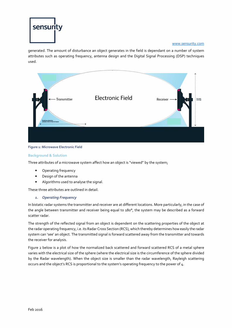
of motion. An electronic field is generated between a transmitter and receiver unit as depicted in Figure 1. The
electronic field is “disturbed” by motion within the field. If the disturbance is great enough an alarm is
www.sensurity.com
Feb 2016
generated. The amount of disturbance an object generates in the field is dependant on a number of system
attributes such as operating frequency, antenna design and the Digital Signal Processing (DSP) techniques
used.
Figure 1: Microwave Electronic Field
Background & Solution
Three attributes of a microwave system affect how an object is “viewed” by the system;
• Operating frequency
• Design of the antenna
• Algorithms used to analyse the signal.
These three attributes are outlined in detail.
1. Operating Frequency
In bistatic radar systems the transmitter and receiver are at different locations. More particularly, in the case of
the angle between transmitter and receiver being equal to 180°, the system may be described as a forward
scatter radar.
The strength of the reflected signal from an object is dependent on the scattering properties of the object at
the radar operating frequency, i.e. its Radar Cross Section (RCS), which thereby determines how easily the radar
system can ‘see’ an object. The transmitted signal is forward scattered away from the transmitter and towards
the receiver for analysis.
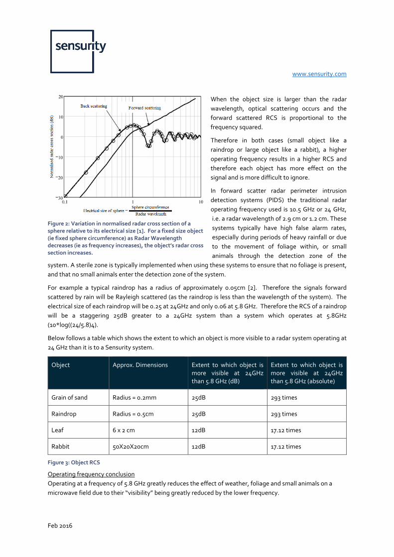
Figure 2 below is a plot of how the normalized back scattered and forward scattered RCS of a metal sphere
varies with the electrical size of the sphere (where the electrical size is the circumference of the sphere divided
by the Radar wavelength). When the object size is smaller than the radar wavelength, Rayleigh scattering
occurs and the object’s RCS is proportional to the system’s operating frequency to the power of 4.
www.sensurity.com
Feb 2016
When the object size is larger than the radar
wavelength, optical scattering occurs and the
forward scattered RCS is proportional to the
frequency squared.
Therefore in both cases (small object like a
raindrop or large object like a rabbit), a higher
operating frequency results in a higher RCS and
therefore each object has more effect on the
signal and is more difficult to ignore.
In forward scatter radar perimeter intrusion
detection systems (PIDS) the traditional radar
operating frequency used is 10.5 GHz or 24 GHz,
i.e. a radar wavelength of 2.9 cm or 1.2 cm. These
systems typically have high false alarm rates,
especially during periods of heavy rainfall or due
to the movement of foliage within, or small
animals through the detection zone of the
system. A sterile zone is typically implemented when using these systems to ensure that no foliage is present,
and that no small animals enter the detection zone of the system.
For example a typical raindrop has a radius of approximately 0.05cm [2]. Therefore the signals forward
scattered by rain will be Rayleigh scattered (as the raindrop is less than the wavelength of the system). The
electrical size of each raindrop will be 0.25 at 24GHz and only 0.06 at 5.8 GHz. Therefore the RCS of a raindrop
will be a staggering 25dB greater to a 24GHz system than a system which operates at 5.8GHz
(10*log((24/5.8)4).
Below follows a table which shows the extent to which an object is more visible to a radar system operating at
24 GHz than it is to a Sensurity system.
Object Approx. Dimensions Extent to which object is
more visible at 24GHz
than 5.8 GHz (dB)
Extent to which object is
more visible at 24GHz
than 5.8 GHz (absolute)
Grain of sand Radius = 0.2mm 25dB 293 times
Raindrop Radius = 0.5cm 25dB 293 times
Leaf 6 x 2 cm 12dB 17.12 times
Rabbit 50X20X20cm 12dB 17.12 times
Figure 3: Object RCS
Operating frequency conclusion
Operating at a frequency of 5.8 GHz greatly reduces the effect of weather, foliage and small animals on a
microwave field due to their “visibility” being greatly reduced by the lower frequency.
Figure 2: Variation in normalised radar cross section of a
sphere relative to its electrical size [1]. For a fixed size object
(ie fixed sphere circumference) as Radar Wavelength
decreases (ie as frequency increases), the object’s radar cross
section increases.
www.sensurity.com
Feb 2016
2. Antenna Design
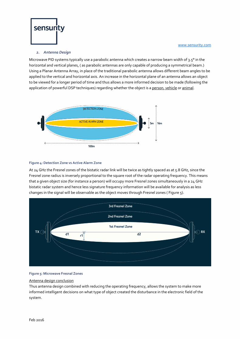
Microwave PID systems typically use a parabolic antenna which creates a narrow beam width of 3.5° in the
horizontal and vertical planes, ( as parabolic antennas are only capable of producing a symmetrical beam.)
Using a Planar Antenna Array, in place of the traditional parabolic antenna allows different beam angles to be
applied to the vertical and horizontal axis. An increase in the horizontal plane of an antenna allows an object
to be viewed for a longer period of time and thus allows a more informed decision to be made (following the
application of powerful DSP techniques) regarding whether the object is a person, vehicle or animal.
Figure 4: Detection Zone vs Active Alarm Zone
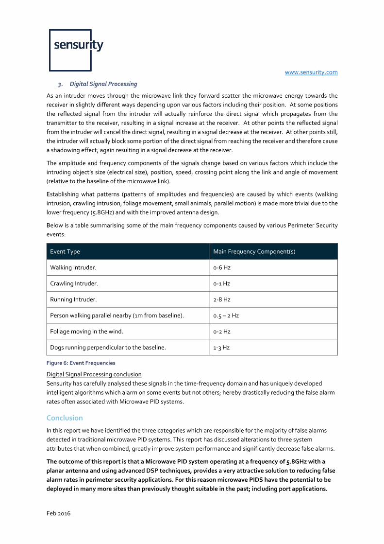
At 24 GHz the Fresnel zones of the bistatic radar link will be twice as tightly spaced as at 5.8 GHz, since the
Fresnel zone radius is inversely proportional to the square root of the radar operating frequency. This means
that a given object size (for instance a person) will occupy more Fresnel zones simultaneously in a 24 GHz
bistatic radar system and hence less signature frequency information will be available for analysis as less
changes in the signal will be observable as the object moves through Fresnel zones ( Figure 5).
Figure 5: Microwave Fresnal Zones
Antenna design conclusion
Thus antenna design combined with reducing the operating frequency, allows the system to make more
informed intelligent decisions on what type of object created the disturbance in the electronic field of the
system.
www.sensurity.com
Feb 2016
3. Digital Signal Processing
As an intruder moves through the microwave link they forward scatter the microwave energy towards the
receiver in slightly different ways depending upon various factors including their position. At some positions
the reflected signal from the intruder will actually reinforce the direct signal which propagates from the
transmitter to the receiver, resulting in a signal increase at the receiver. At other points the reflected signal
from the intruder will cancel the direct signal, resulting in a signal decrease at the receiver. At other points still,
the intruder will actually block some portion of the direct signal from reaching the receiver and therefore cause
a shadowing effect; again resulting in a signal decrease at the receiver.
The amplitude and frequency components of the signals change based on various factors which include the
intruding object’s size (electrical size), position, speed, crossing point along the link and angle of movement
(relative to the baseline of the microwave link).
Establishing what patterns (patterns of amplitudes and frequencies) are caused by which events (walking
intrusion, crawling intrusion, foliage movement, small animals, parallel motion) is made more trivial due to the
lower frequency (5.8GHz) and with the improved antenna design.
Below is a table summarising some of the main frequency components caused by various Perimeter Security
events:
Event Type Main Frequency Component(s)
Walking Intruder. 0-6 Hz
Crawling Intruder. 0-1 Hz
Running Intruder. 2-8 Hz
Person walking parallel nearby (1m from baseline). 0.5 – 2 Hz
Foliage moving in the wind. 0-2 Hz
Dogs running perpendicular to the baseline. 1-3 Hz
Figure 6: Event Frequencies
Digital Signal Processing conclusion
Sensurity has carefully analysed these signals in the time-frequency domain and has uniquely developed
intelligent algorithms which alarm on some events but not others; hereby drastically reducing the false alarm
rates often associated with Microwave PID systems.
Conclusion
In this report we have identified the three categories which are responsible for the majority of false alarms
detected in traditional microwave PID systems. This report has discussed alterations to three system
attributes that when combined, greatly improve system performance and significantly decrease false alarms.
The outcome of this report is that a Microwave PID system operating at a frequency of 5.8GHz with a
planar antenna and using advanced DSP techniques, provides a very attractive solution to reducing false
alarm rates in perimeter security applications. For this reason microwave PIDS have the potential to be
deployed in many more sites than previously thought suitable in the past; including port applications.

www.sensurity.com
Feb 2016
For more information or to find out the benefits of Microwave Perimeter Intrusion Detection Systems (PIDS):
CONTACT
George Redpath PhD CEng FIET
Sensurity - Technical Director [email protected] www.sensurity.com
ACKNOWLEDGEMENTS:
This paper research was greatly supported by Maria Heneghan, Field Applications Engineer, Sensurity Ltd.