Embed Size (px)
Citation preview

Radi
omon
itorin
g &
Radi
oloc
atio
n
Appl
icat
ion
Broc
hure
| 01
.00
Rece
iver
requ
irem
ents
for a
TD
OA-b
ased
radi
oloc
atio
n sy
stem
Receiver requirements for a TDOA-based radiolocation system
Receiver_requirements_app-bro_en_3606-9162-92.indd 1 24.10.2013 14:41:53

2
Contents
Products from Rohde & Schwarz ❙ R&S®ESMD wideband monitoring receiver ❙ R&S®EB500 monitoring receiver ❙ R&S®EM100 digital compact receiver ❙ R&S®UMS monitoring and direction finding system
Monitoring receivers must meet certain requirements to be used in a TDOA-based radiolocation system. This application brochure describes these requirements as well as other parameters that are of interest when selecting sensors.
Introduction ................................................................. 3
Rohde & Schwarz sensor technology for TDOA networks .......................................................... 4
TimestampinI/Q data................................................ 5Basics...... ...................................................................... 5Referencing the timestamp to the receiver antenna input...... ............................................. 5Accuracy of the receiver's internal clock ....................... 6Importance of an absolute timestamp .......................... 6
Important parameters for a TDOA sensor .............. 7Frequency accuracy ...................................................... 7Noise and linearity ......................................................... 8GPS...... .......................................................................... 9Timestamp accuracy ................................................... 10
Summary ................................................................... 11
Receiver_requirements_app-bro_en_3606-9162-92.indd 2 24.10.2013 14:41:53

Rohde & Schwarz Receiver requirements for a TDOA-based radiolocation system 3
Introduction Emitter location based on measuring the time difference of arrival (TDOA) at multiple receiver sites has been available for several decades. In the past, the greatest challenge lay in time-synchronizing the various spatially separated re-ceiver sites. Extremely complex methods were needed to precisely synchronize multiple receivers. Without adequate synchronization, the results of this location method are unusable because even small synchronization errors lead to significant errors in emitter location. For example, when using a single sensor, an error of 100 ns in measured time means an error of 30 m in the estimated distance. When using multiple sensors, the errors are additive and lead to unusable location results.
Today, GPS signals are used almost exclusively to synchro-nize multiple receiver sites. This provides the accuracy needed for the resulting TDOAs to be used in locating the signal source.
Radiolocation accuracy and reliability depend on the time information from the receiver's high-precision internal clock being inserted in the digital baseband data stream (I/Q data).
Further parameters and characteristics relevant for a re-ceiver to be used as a TDOA sensor are described in detail below.
Receiver_requirements_app-bro_en_3606-9162-92.indd 3 24.10.2013 14:41:53

max. 10 km
¸UMS
¸DDF255
¸EM100¸EM100
¸DDF255
4
Multiple products in a single system
Rohde & Schwarz sensor technology for TDOA networks
The advantage of a Rohde & Schwarz TDOA system lies in the flexibility in choosing the sensor equipment. The uni-form data format, together with the delay compensation implemented in all receivers, makes it possible to build custom combinations of sensors in a TDOA network. The monitoring receivers can be selected to meet site-specific requirements. Where ITU-compliant measurements are required in addition to I/Q data recording for TDOA loca-tion, the R&S®ESMD wideband monitoring receiver or the R&S®EB500 monitoring receiver can be used. Both can be connected to sensors based on the R&S®EM100 digi-tal compact receiver, for example, to combine them into a TDOA system. The R&S®EM100 is used at sites where simple monitoring or measurement tasks are additionally performed.
In addition to purely technical criteria, the installation effort plays a key role. Rohde & Schwarz monitoring receivers come in a standard housing for rack installation (except for the R&S®PR100). As a result, they are suited both for vehicular and stationary use at a monitoring site. Exter-nal housing is required for outdoor mast installation. In this case, the monitoring receivers are integrated into an R&S®UMS monitoring and direction fi nding (DF) system. Depending on the configuration, this system includes re-ceivers plus additional equipment for remote operation in weatherproof housing (for example, a PC and a tempera-ture control to accommodate for an extended tempera-ture range). The R&S®UMS documentation (e.g. product brochure PD 5214.3575.12) defines the suitability of an R&S®UMS system for TDOA location and describes pos-sible system configurations.
Rohde & Schwarz monitoring receivers are available as or can be expanded to function as single-channel direction finders (except for the R&S®EB510). Depending on the frequency range, DF results are generated based on the Watson-Watt or the correlative interferometer DF method, using the appropriate DF antennas. The DF method em-ployed does not affect a monitoring receiver's use in a TDOA network. Rohde & Schwarz not only combines TDOA with conventional angle of arrival (AoA) direction finding within a TDOA network, but also offers the functionality of both methods in one instrument. This makes the advan-tages of both methods available in a hybrid radiolocation system to deliver the most accurate location result pos-sible. The challenge is that the radiolocation system must be capable of processing result data generated with both methods.
ReceiverssuitableforuseinaTDOAnetworkReceiver Synchronization with GPS module Brochure
Internal External Order No.
R&S®ESMD ● ● PD 5213.9863.12
R&S®EB500 ● PD 5214.3800.12
R&S®EM100 ● PD 5214.0560.12
Rohde & Schwarz monitoring receivers form the core of the sensor equipment used in a TDOA network. All moni-toring receivers and direction finders supply uniform I/Q data including timestamps via LAN. The I/Q data is always timestamped by the receiver's internal clock – with an al-lowance for the internal signal delays – regardless of how accurate the internal clock is. A receiver's suitability for use as a sensor in a TDOA network therefore depends on the synchronization options for the internal clock. All mon-itoring receivers can be synchronized via an external GPS module. For information about delay compensation and timestamp accuracy as well as synchronization options for the internal GPS module, refer to the product brochures (see table) and data sheets for the various monitoring receivers.
Receiver_requirements_app-bro_en_3606-9162-92.indd 4 24.10.2013 14:41:53

Receiver 2
Receiver 1
t2
t1
Receiver 3
t3
Receiver 2
Receiver 1
t2
t1
Signal arrival Correlogram
10.80.60.40.2
00 54321 ∆τ
tReceiver 1
tReceiver 2
t
t
t
∆τ
∆τ
∆τ
Rohde & Schwarz Receiver requirements for a TDOA-based radiolocation system 5
Timestamp in I/Q data
BasicsTDOA-based radiolocation systems require at least three receivers in order to calculate an unambiguous location result. By cross-correlating the signals received at different sites, it is possible to determine the relative difference in the delay for these signals between two sites. This relative delay difference produces a hyperbolic curve on a map. Ideally, the emitter will be located along this curve. Adding the third receiver generates two more hyperbolic curves. The three hyperbolic curves will ideally intersect at a single point; this intersection is the origin of the signal.
A hyperbolic curve is calculated by cross-correlating the I/Q data of two receivers. However, in order to obtain a rel-ative delay difference from cross-correlating the I/Q data, this I/Q data must include highly precise time information. This is the greatest challenge, because different receiver settings produce different signal delays within the instru-ment. For example, the selected center frequency will af-fect the signal path or the characteristics of the preselec-tion filter, just as changing the bandwidth will affect the sampling rate. To ensure that I/Q data carries precise and absolute time information (referenced to universal time coordinated; UTC), the signal delays associated with all possible receiver settings must be known and taken into account when inserting the timestamp into the I/Q data.
Referencing the timestamp to the receiver antenna inputIn order to achieve maximum independence and flexibil-ity in a TDOA system, the time information in the I/Q data should reflect the point in time at which a signal arrives at the receiver's antenna input. The exact signal delays must be known for all possible settings in the receiver. Because the timestamp cannot be inserted into the I/Q data before the receiver's digital section, the signal delays until time-stamp insertion must additionally be taken into account. Delay compensation and referencing the timestamp to the antenna input is mandatory in order to combine different types of receivers into a TDOA network because different receiver types will cause different delay errors.
The more complex the receiver hardware ( resulting in more combinations of signal paths), the greater the effort required to implement delay compensation. Rohde & Schwarz receivers contain a correction table that lists the delays for all possible receiver settings. This in-cludes any influences from the analog hardware as well as delays originating in the digital section. The correction table facilitates the work of system integrators, because they only need to consider external delays starting at the receiver's antenna input (for example, different cable lengths to the antenna). To generate the correction table, the signal delays are calculated for all possible receiver settings. The benefits of having a correction table are obvi-ous when receivers of different types are combined in a
Determining the delay difference from I/Q data
Emitter location at the intersection of three hyperbolic curves
Receiver_requirements_app-bro_en_3606-9162-92.indd 5 24.10.2013 14:41:54
Pre-selection
Front-end
Digital signal processing
∆t
Antenna input
AD
6
system: To reduce costs, a TDOA system is ideally com-posed of an identical set of the most cost-effective receiv-ers possible, because TDOA systems require more sensors than conventional direction finding networks. In densely built-up urban environments, a hybrid configuration made up of compact and higher-end receivers with good RF characteristics is recommended. Signal reception in such congested scenarios is better with receivers that exhibit good RF characteristics.
Users should therefore be able to select different receivers for different sites, for example in order to optimize signal reception in the vicinity of strong transmitters.
Receiverblockdiagram
Note
When a TDOA network uses identical sensors, signal delay compen-
sation should be employed in the receivers. Otherwise, all of the sen-
sors used in a measurement would need to have exactly the same
settings. This is because different settings in the receivers would lead
to different internal signal delays and cause an excessive delay error.
A TDOA network requires many carefully selected sites for placing the
sensors. If different types of sensors with built-in delay compensation
are available, they can be used to perform additional measurements
at the various sites. This provides significant cost savings, for example
where ITU-compliant monitoring receivers are used for radiolocation
in a TDOA network. If receivers at existing measurement sites can be
expanded to include GPS time synchronization functionality, hardware
costs will also be reduced.
Accuracyofthereceiver'sinternalclockThe accuracy of a monitoring receiver's internal crystal os-cillator typically ranges from 0.1 ppm to 1 ppm – in the ab-sence of any external synchronization. Even if the internal clock is set to the precise GPS time, it would very quickly become too inaccurate for a TDOA system because of the drift of the receiver's internal reference frequency. Repeated adjustment of the clock time is not practicable because having multiple clock times defined can lead to inconsistencies in the data stream. This means that, in ad-dition to synchronizing the internal clock, the stability or accuracy of the internal reference frequency must also be enhanced. In addition to the position and time informa-tion, GPS receivers can also deliver a pulse per second (PPS) signal. However, this pulse is subject to strong jitter on many GPS modules, which disqualifies them for TDOA purposes. High-end GPS receivers, on the other hand, exhibit absolute accuracy in the double-digit nanosecond range. The PPS is used to stabilize the internal reference frequency of the monitoring receiver, ideally providing accuracy in the picosecond range. With this additional control, the receiver's internal clock needs to be set to the GPS clock only once and then adjusted with the high- precision internal reference frequency.
Importance of an absolute timestampBoth referencing the timestamp to the antenna input and increasing internal clock accuracy are necessary to ensure that an absolute, UTC-referenced timestamp is inserted into the I/Q data stream. If there is no delay compensation in the receiver, the time to which the timestamp is refer-enced will be undefined.
The I/Q data stream generated by the receiver consists of individual packets with headers plus the actual I/Q sam-ples. The header contains the absolute timestamp and the current sampling rate at which I/Q data is generated in the receiver. This means that for each sample pair the time of arrival at the receiver's antenna input is precisely defined. Rohde & Schwarz monitoring receivers always include this time information in the I/Q data stream, so the receivers are not limited to a specific TDOA mode.
Recordings from the I/Q data stream can also subsequent-ly be used for TDOA location. Offline TDOA location is useful, for example, where a satisfactory data connection cannot be established to sensor sites. This requires record-ings from three different sites of the same frequency at the same time, and also that the same signal be received at all sites.
Receiver_requirements_app-bro_en_3606-9162-92.indd 6 24.10.2013 14:41:54

–3σ –2σ –σ +σ +2σ +3σx
68.3 %
95.5 %
99.7 %
Receiver 2
Receiver 1
Effect on hyperbolic curves
Correlograms of consecutive measurements with poor short-term stability
Rohde & Schwarz Receiver requirements for a TDOA-based radiolocation system 7
Important parameters for a TDOA sensor
When selecting the sensors for a TDOA system, a number of parameters relevant to the system's positioning accura-cy need to be given consideration. These parameters and their mutual relationships are described here based on the example of the R&S®ESMD wideband monitoring receiver.
Frequency accuracyThe accuracy of the receiver's internal clock essentially de-pends on the accuracy of the internal reference frequency, since the clock signal is derived from the internal reference frequency. The accuracy of the receiver's internal standard crystal oscillator is not adequate for TDOA purposes when there is no external reference and internal control. This is why specifying the internal reference frequency accuracy without including external control is useless when select-ing sensors for a TDOA network. The critical information is instead the accuracy of the internal reference frequency with additional external control, such as a GPS signal. Of particular importance are the short-term stability and the frequency accuracy averaged over a longer period of time (e.g. 24 h).
Short-term stabilityThe short-term stability of the internal reference frequency influences the location results of a TDOA system. The higher the short-term stability, the less sequential cross-correlation results will deviate from one another. The hy-perbolic curves follow the same pattern. The stability of the location result therefore depends directly on the short-term stability of the internal reference frequency.
As this parameter is a normally distributed value, it is ex-pressed statistically. For a defined observation period τ a standard deviation σ results that statistically speaking en-compasses 68.3 % of all measured values. The mean value in this case is zero (no deviation).
If the observation period τ is extended, the standard de-viation σ decreases. Short observation times (of several seconds) are used to estimate the fluctuation of sequential results. The short-term stability of the R&S®ESMD is as fol-lows: τ = 2 s; σ = 2 × 10⁻¹⁰ 1).
Poor short-term stability of the internal reference frequen-cy increases the spread of the hyperbolic curves used for TDOA location. When combining the hyperbolic curves from different receivers to obtain an emitter location, these spreads are additive and reduce the accuracy of the loca-tion result.
1) See data sheet PD 5213.9863.22.
Graphical representation of a normally distributed value
Effect of poor short-term stability of internal reference frequency
Receiver_requirements_app-bro_en_3606-9162-92.indd 7 24.10.2013 14:41:54

A
Narrowband signal Wideband signal
f
A
fL0ffL0
8
Average frequency accuracy (GPS-supported)Another important parameter for the accuracy of the inter-nal reference frequency is the value averaged over several hours. This parameter indicates to what extent the internal reference frequency actually deviates from 10 MHz over a longer period of time. If the receiver's internal clock is too fast or too slow, this will eventually affect the accuracy of the internal time. Even if the receiver time is only slightly off, the calculated hyperbolic curves will not pass through the actual origin of the signal. The R&S®ESMD has a fre-quency accuracy of < ± 5 × 10–12; ± 0.5 × 10⁻¹² (typ.; GPS-supported, averaged over 24 h). 2)
If the internal reference frequency exhibits good short-term stability and poor long-term stability, users neverthe-less obtain a stable location result. However, the result does not represent the actual signal origin. Since there is no quality indication for location results, results will always exhibit the same systematic error if one of the sensors has poor long-term stability and its internal time deviates from the absolute (UTC-referenced) time. The internal reference frequency must therefore also exhibit very good long-term stability.
The higher the accuracy of the internal reference fre-quency (averaged over several hours), the less the internal times of the various sensors will diverge from the absolute time over an extended period of operation, and the more precise the system's location results will be.
Noise and linearityThe effects of noise and linearity are often ignored when considering the parameters important for TDOA. These ef-fects are less apparent than that of the internal reference frequency, for example. The general requirements applica-ble to every radiomonitoring and spectrum monitoring sys-tem also apply to TDOA systems. The accuracy of a TDOA system depends on the bandwidth of the signal being lo-cated, with wideband signals providing less accuracy.
2) See data sheet PD 5213.9863.22.
The linearity of a monitoring receiver is particularly impor-tant if weak signals are to be located together with strong signals. A receiver's large signal immunity plays a signifi-cant role particularly in urban environments, where many strong signals are present.
A receiver's inherent noise will primarily affect its sensitiv-ity. Detecting and locating weak signals therefore requires receivers with extremely high sensitivity and a low noise figure.
Based on cross-correlation of I/Q data from multiple receivers, the TDOA method is suitable for handling wideband signals. When locating narrowband signals ( approx. < 200 kHz), receiver characteristics that reduce the signal-to-noise ratio are critical as they more strongly influence the location result.
The near-carrier phase noise from a receiver's local oscil-lators must also be taken into account. To convert a signal received at the antenna input to the IF range, this signal is multiplied several times with signals from the receiver's local oscillators. The phase noise from the local oscillators degrades the quality of the received signal. This effect is inherent in the superheterodyne principle, but there is no practicable alternative in the VHF/UHF frequency range. The effect of phase noise can be reduced by using low-noise oscillators. Phase noise is dependent on frequency and temperature, but not on the set receiver bandwidth. The impact of near-carrier phase noise varies significantly depending on the bandwidth of the received signal. While it is almost negligible for wideband signals, near-carrier phase noise significantly degrades the correlation result for narrowband signals (approx. < 200 kHz), leading to a large spread in the displayed result and making it almost impossible to locate narrowband signals.
Effect of phase noise (blue) on narrowband and wideband signals (black)
Receiver_requirements_app-bro_en_3606-9162-92.indd 8 24.10.2013 14:41:54

Rohde & Schwarz Receiver requirements for a TDOA-based radiolocation system 9
Noise and linearity must be taken into consideration when using a TDOA radiolocation system in a city or another environment with an abundance of strong signals. If the system is to be used to reliably locate narrowband signals as well, the sensors must be chosen to minimize near-car-rier phase noise. For example, if a sensor with insufficient large signal immunity is placed in the vicinity of a strong transmitter, external channel filters can be used to reduce the effects of strong signals and allow reliable location also of narrowband signals. However, this solution requires ad-ditional integration effort since the effects of group delay in external filters must additionally be compensated. Oth-erwise, the timestamp accuracy would be too strongly af-fected by the delays in the external filters. When planning a TDOA system, users should be able to choose from a set of different sensors in order to optimally adapt the sensor equipment to the environment without requiring any ad-ditional effort.
GPSThe GPS signal is used in a TDOA sensor to determine the sensor position as well as for time and frequency syn-chronization. Ideally, it will be possible to influence the GPS module parameters directly from the system, so that by averaging the GPS signals, both the position accuracy and the time accuracy will be improved. The optional R&S®ESMD-IGT internal GPS module can be operated in various modes in order to increase time accuracy. The set-ting options for the GPS module are described in the ap-plication card “Increasing timestamp accuracy in TDOA applications” (PD 3606.7530.92).
Time accuracy is a critical parameter for a GPS module to be used in a TDOA network. A TDOA sensor's internal clock cannot be more accurate than the clock in the GPS module used for synchronization. It is therefore mandatory to specify the time accuracy for the GPS reference in the TDOA sensor's technical data. Most data sheets express the time accuracy by the PPS accuracy. This is the abso-lute accuracy of the PPS referenced to UTC.
Note
The accuracy of the GPS reference is the critical criterion when gen-
erating timestamps in the I/Q data stream, as it is used to synchro-
nize the TDOA sensor's internal clock. In many data sheets for TDOA
sensors, only the GPS reference accuracy is specified. However, this
parameter does define the accuracy of the timestamp in the I/Q data
stream; instead, the timestamp accuracy must be separately calcu-
lated, measured and specified.
While it is interesting to know the horizontal position accuracy of
a GPS module, this is not critical for TDOA applications. The error
caused in a TDOA system by incorrect time information is typically
greater than any errors resulting from inadequate position accuracy of
a GPS module. Specifying a GPS module's horizontal position accu-
racy is useful in eliminating error sources during emitter location.
GPS (requires R&S®ESMD-IGT option)Receiver type 50 channels, GPS L1 frequency,
C/A code, SBAS: WAAS, EGNOS, MSAS
Horizontal position accuracy (CEP 50 %, 24 h static, –130 dBm, SEP < 3.5 m)
without satellite-based augmentation system (SBAS)
2.5 m
with SBAS 2.0 m
PPS accuracy (with good GPS signal)
RMS 30 ns
99 % 60 ns
Receiver_requirements_app-bro_en_3606-9162-92.indd 9 24.10.2013 14:41:54

I/Q data with timestamp GPS antenna
Digital signal processing
GPS module
GPS time
PPS
Time
Delay compensationAntenna
input
Control loop
Int. referenceDA
Analog section (different delays)
10
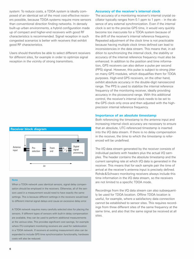
Absolute timestamp accuracyA TDOA sensor's technical data must also include the ab-solute accuracy of the timestamp with reference to UTC. This value encompasses the influences from all param-eters that affect the receiver's timing characteristics: inter-nal reference frequency, GPS synchronization and delay compensation.
Consequently, absolute timestamp accuracy is the most important value for a receiver to qualify for use in a TDOA network. It specifies to what extent the timestamp ref-erenced to the antenna input deviates from UTC (stated statistically). The deviation can be even greater when add-ing up all error sources involved in timestamp generation, making any guaranteed value significantly higher than the specified standard deviation. It is more realistic to specify a statistical value calculated over multiple measurements, since TDOA systems use multiple consecutive mea-sured values for locating a signal source (thus increasing accuracy).
TimestampAccuracy 1) 2) of timestamp versus frequency with external reference frequency and referenced to externally supplied PPS
20 MHz to 50 MHz < ±100 ns
50 MHz to 26 500 MHz < ±100 ns, ±50 ns (typ.)
HF option
1 MHz to 5 MHz < ±200 ns
5 MHz to 32 MHz < ±100 ns, ±50 ns (typ.)
Accuracy 1) 2) 3) 4) of timestamp, GPS-supported standard deviation with 2 000 measurements < 10 ns
1) Measured with 20 MHz IF bandwidth, IF equalizer active, 150 kHz demodulation bandwidth. 2) Timestamp referenced to antenna input.3) Conditions: good GPS signal, fixed GPS antenna position, GPS antenna position known with standard deviation of < 0.1 m, constant temperature.4) Frequency 250 MHz. TDOA generator and receiver each GPS-synchronized via its own GPS antenna; identical lines of sight to satellites.
Components relevant to timestamp accuracy
Timestamp accuracyAccuracy of timestamp versus frequencyA TDOA sensor's technical data must include the delay compensation in the receiver (see page 5), where im-plemented. The entire frequency range should be covered, since different signal paths are used in the receiver de-pending on the frequency range. This presents the great-est challenge for delay compensation. The resulting value does not indicate the timestamp's accuracy with reference to UTC, but rather how accurately the timestamp reflects the arrival time of the signal at the antenna input. The smaller the deviation, the less location results will be af-fected by the receiver's internal signal processing.
Receiver_requirements_app-bro_en_3606-9162-92.indd 10 24.10.2013 14:41:54

Rohde & Schwarz Receiver requirements for a TDOA-based radiolocation system 11
Summary Rohde & Schwarz sensors fully provide the required TDOA functionality.
All receiver characteristics that affect location results have been optimized. Systems can easily be adapted to specific environments by using a mix of sensors. This also increas-es flexibility during system development and enhances the quality of location results.
The sensors from Rohde & Schwarz can be used for both TDOA and angle of arrival (AoA) location, making it possi-ble to build hybrid radiolocation systems. The appropriate radiolocation method can be selected to achieve the best possible results for a given application.
The data sheets for the Rohde & Schwarz sensors detail all important parameters necessary to evaluate their suit-ability in a TDOA system. Customers have everything they need to design an ideal system, even when combining sensors of different types or building a hybrid system.
Receiver_requirements_app-bro_en_3606-9162-92.indd 11 24.10.2013 14:41:54

3606
.916
2.92
01.
00 P
DP
1 e
n
Certified Quality System
ISO 9001
R&S® is a registered trademark of Rohde & Schwarz GmbH & Co. KG
Trade names are trademarks of the owners
PD 3606.9162.92 | Version 01.00 | October 2013 (sk)
Receiver requirements for a TDOA-based radiolocation system
Data without tolerance limits is not binding | Subject to change
© 2013 Rohde & Schwarz GmbH & Co. KG | 81671 München, Germany
About Rohde & SchwarzRohde & Schwarz is an independent group of companies specializing in electronics. It is a leading supplier of solu-tions in the fields of test and measurement, broadcasting, radiomonitoring and radiolocation, as well as secure communications. Established more than 75 years ago, Rohde & Schwarz has a global presence and a dedicated service network in over 70 countries. Company headquar-ters are in Munich, Germany.
Environmental commitment ❙ Energy-efficient products ❙ Continuous improvement in environmental sustainability ❙ ISO 14001-certified environmental management system
Rohde & Schwarz GmbH & Co. KGwww.rohde-schwarz.com
Regional contact ❙ Europe, Africa, Middle East | +49 89 4129 12345 [email protected]
❙ North America | 1 888 TEST RSA (1 888 837 87 72) [email protected]
❙ Latin America | +1 410 910 79 88 [email protected]
❙ Asia/Pacific | +65 65 13 04 88 [email protected]
❙ China | +86 800 810 8228/+86 400 650 5896 [email protected]
3606916292
Service that adds value❙ Worldwide ❙ Local and personalized❙ Customized and flexible❙ Uncompromising quality ❙ Long-term dependability
3606
.916
2.92
01.
00 P
DP
1 e
n
Receiver_requirements_app-bro_en_3606-9162-92.indd 12 24.10.2013 14:41:55