Embed Size (px)
Citation preview

Test
& M
easu
rem
ent
Appl
icat
ion
Broc
hure
| 01
.00
OTA
perf
orm
ance
mea
sure
men
ts
of M
IMO-
enab
led
devi
ces
OTA performance measurements of MIMO-enabled devices
Cost-effective solution with 3D evaluation and easy-to-use test setup

2
Contents MIMO OTA performance testing .............................. 3Key facts ........................................................................ 3
New test methods for MIMO OTA measurements ............................................................ 4Testing different MIMO operation modes ..................... 4Full 3D evaluation for realistic test results ..................... 5
Cost- effective MIMO OTA measurements .............. 6R&S®TS8991 MIMO OTA performance test system ...... 6Includes SISO measurements without changes to test setup ....................................................................... 7Verification of smart UE receive antennas ..................... 7Extension of SISO chamber for MIMO testing .............. 7
Clearly structured MIMO OTA test plan .................. 8Noise-limited OTA performance in transmit diversity mode (NLTD) ................................................................. 8Peak performance measurements in spatial multiplexing mode(PPSM) ............................................ 9
Statistical evaluation of OTA measurements indicates network performance ............................. 10
Conclusive test results through conducted and radiated measurements ........................................... 12
Automated measurements with ready-to-use test templates ........................................................... 13OTA measurements – SISO and MIMO ....................... 13Test procedure flexibility .............................................. 13Standard-specific templates included ......................... 13Network operator test solution .................................... 13Result documentation made easy ............................... 13
Glossary ..................................................................... 14
Ordering information ............................................... 15
Applicable Rohde & Schwarz product:R&S®TS8991 test system
Modern wireless devices provide a carefully engineered target shape radiation pattern and largely uniform antenna sensitivity pattern in all directions. The Rohde & Schwarz MIMO OTA test method is a cost-effective extension to the established R&S®TS8991 SISO solution. Highly reproducible reliable scalar results with full spherical evaluation are obtained.

Rohde & Schwarz OTA performance measurements of MIMO-enabled devices 3
MIMO OTA performance testing
Anechoic test chamber for MIMO OTA measurements.
To obtain a complete picture of MIMO OTA performance, user equipment (UE) needs to be tested under varying orientations in a 3D environment. The device under test (DUT) is positioned inside the fields of two moving, cross-polarized test antennas, each radiating different signals of a transmit diversity or spatial multiplexed MIMO downlink. Repeating the measurements in several different geometri-cal constellations and polarizations provides a comprehen-sive overview of UE antenna characteristics.
Key facts ❙ VerifiesMIMOperformanceinfreespaceorwithaphantom head and/or hand, for maximum reality in test results
❙ Cost-effective solution with easy-to-use test setup ❙ Simple upgrade of existing SISO OTA test systems ❙ Simulates any possible UE antenna orientation ❙ Statistical metrics indicate the performance of the UE in the network
❙ No channel emulator required ❙ High reproducibility between test laboratories ❙ Clearly structured test plan
Multiple input multiple output (MIMO) techniques have been introduced to improve network performance for data applications in particular. The channel capacity of the al-located frequency spectrum is increased by making use of spatial multiplexing. In the case of 2x2 downlink MIMO, the data throughput can be doubled compared to SISO operation. This results in added device complexity and a more cluttered angular pattern.
Data throughput gains in MIMO mode are verified by manufacturers, test houses and network operators. Mea-surements in conducted mode (with channel emulation) focus on the RF frontend characteristics in conjunction with the receiver firmware implementation.
Radiated mode measurements help to identify whether the antenna subsystem comprising RF frontend and an-tennas is responsible for variations in device performance.

4
Currently, OTA performance tests for single input single output (SISO) devices are standardized for 2G and 3G mobile radio and WLAN. These tests provide vital infor-mation about the behavior of user devices in a network. The 3D angular patterns of both the output power and the receiver sensitivity are typically measured in an anechoic environment, and used to derive figure of merits (FOM) as specified by CTIA, and similarly by 3GPP: ❙ Total radiated power (TRP) ❙ Total isotropic sensitivity (TIS)
Testing different MIMO operation modesIn MIMO 2x2 mode there are two downlink data streams, and the user equipment has two receiving antennas. The correlation of the UE’s RX antennas needs to be as low as possible to achieve a good separation of simultaneously received data streams. To evaluate the performance of the antenna subsystem, it is not sufficient to analyze the pat-tern of each receiving antenna separately in passive mode only. Using the RF frontend to establish a real-world load for the antennas and contribute noise terms to the input signal streams is the more realistic case.
OTA performance tests can verify the following transmis-sion modes: ❙ SISO as basic operation mode ❙ Transmit diversity with redundant data streams for an increased signal range
❙ Spatial multiplexing with multiple data streams for higher data throughput
New test methods for MIMO OTA measurements
General radio downlink transmission in MIMO 2x2 mode
BS
x1(i) x2(i)
UE
y1(i) y2(i)
P V
R2(φ, Θ)
R1(φ, Θ)
T2(φ, Θ)
T1(φ, Θ)

Rohde & Schwarz OTA performance measurements of MIMO-enabled devices 5
3D distribution of effective isotropic sensitivity (MIMO 2x2).
Full 3D evaluation for realistic test resultsWireless devices are operated in arbitrary positions. Fur-thermore, signal propagation will create signals arriving from arbitrary directions. As a result, full 3D evaluation is required to assess the impact on antenna performance of multipath reception, from all angles of arrival (AoA). A test approach that makes it possible to locate either of the two transmit test antennas at any point on a sphere centered on the DUT, providing simulated real-world test conditions.

6
Cost- effective MIMO OTA measurements
R&S®TS8991 MIMO OTA performance test systemThe R&S®TS8991 OTA performance test system also sup-ports MIMO OTA measurements 1). The concept is based on a conventional SISO OTA test chamber and contains two conical cut positioners. Both carry dual-polarized test antennas, TA1 and TA2, that provide the DL signal. TA1 and TA2 may be moved independently of each other, al-lowing a wide angle of arrival spread for the signals to be generated. The UE is placed on an azimuth positioner containing a communications antenna (COMM ANT) for the uplink path. The 3D evaluation uses test antennas that move independently over the surface of a sphere in space centered on the DUT.
Test instruments include the R&S®CMW500 wideband radio communication tester as base station emulator (BSE) and the R&S®OSP130 open switch and control platform as switch matrix.
1) More details available in Rohde & Schwarz white paper 1SP12 “Two-Channel Method for OTA Performance Measurements of MIMO-Enabled Devices”.
Principle of Rohde & Schwarz two-channel method for MIMIO 2x2 mode
Cross-polarized test antennas provide four polarization combinations.
BSE
x1(i) x2(i)UE
y1(i) y2(i)
P V
R1(Ω1), R2(Ω1)
Tq2(Ω2)
R1(Ω2), R2(Ω2)
Tp1(Ω1)
A

Rohde & Schwarz OTA performance measurements of MIMO-enabled devices 7
Extension of SISO chamber for MIMO testingMost existing manufacturer’s SISO setups can be up-graded to cover MIMO testing. Chambers used for today’s SISO OTA work are typically large enough to accommo-date the R&S®AMS32 MIMO-OTA upgrade. A second dual-polarized test antenna with dedicated elevation positioner is added.
Includes SISO measurements without changes to test setupSISO OTA measurements for 2G and 3G legacy technolo-gies are a mandatory part of device characterization. Thanks to the unique two-channel method devised by Rohde & Schwarz, the anechoic chamber can be used for both SISO and MIMO tests without hardware modifica-tion; one of the cross-polarized test antennas is simply driven into a non-interfering parking position.
Measurements in free space as well as with phantom head and/or hand are possible in SISO and MIMO mode.
Verification of smart UE receive antennasThe two-channel method can also verify the performance of smart UE antennas with adaptive receiving character-istics. This is assured since the two-channel method does not require any auxiliary RF cabling connected to the an-tenna ports of the UE during the test. Therefore the inter-face between antenna and RF frontend is untouched – the actual UE antennas are connected to their real-world load impedance during the test.
Main components of the R&S®TS8991 OTA performance test system for MIMO
¸CMW500
DL1φ
DL1Θ
DL2φ
DL2Θ
UL
¸OSP130
COMM ANT
φ
Θ2 Θ1
TA2
Θ 2 p
ositi
oner
Θ 1 p
ositi
oner
TA1
8
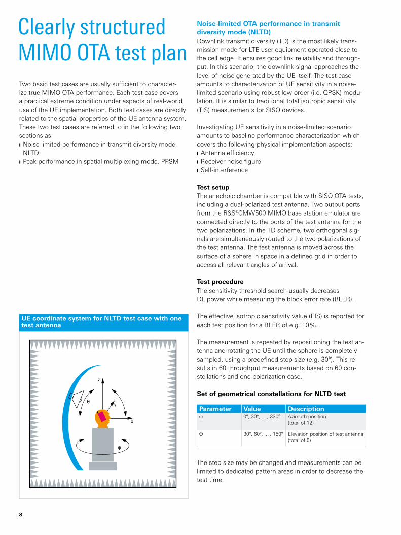
Noise-limited OTA performance in transmit diversity mode (NLTD)Downlink transmit diversity (TD) is the most likely trans-mission mode for LTE user equipment operated close to the cell edge. It ensures good link reliability and through-put. In this scenario, the downlink signal approaches the level of noise generated by the UE itself. The test case amounts to characterization of UE sensitivity in a noise-limited scenario using robust low-order (i.e. QPSK) modu-lation. It is similar to traditional total isotropic sensitivity (TIS) measurements for SISO devices.
Investigating UE sensitivity in a noise-limited scenario amounts to baseline performance characterization which covers the following physical implementation aspects: ❙ Antennaefficiency ❙ Receivernoisefigure ❙ Self-interference
Test setupThe anechoic chamber is compatible with SISO OTA tests, including a dual-polarized test antenna. Two output ports from the R&S®CMW500 MIMO base station emulator are connected directly to the ports of the test antenna for the two polarizations. In the TD scheme, two orthogonal sig-nals are simultaneously routed to the two polarizations of the test antenna. The test antenna is moved across the surface of a sphere in space in a defined grid in order to access all relevant angles of arrival.
Test procedureThe sensitivity threshold search usually decreases DL powerwhilemeasuringtheblockerrorrate(BLER).
The effective isotropic sensitivity value (EIS) is reported for each test position for a BLER of e.g. 10 %.
The measurement is repeated by repositioning the test an-tenna and rotating the UE until the sphere is completely sampled, using a predefined step size (e.g. 30°). This re-sults in 60 throughput measurements based on 60 con-stellations and one polarization case.
Set of geometrical constellations for NLTD test
Parameter Value Descriptionφ 0°, 30°, ... , 330° Azimuth position
(total of 12)
Θ 30°, 60°, ... , 150° Elevation position of test antenna (total of 5)
The step size may be changed and measurements can be limited to dedicated pattern areas in order to decrease the test time.
Two basic test cases are usually sufficient to character-ize true MIMO OTA performance. Each test case covers a practical extreme condition under aspects of real-world use of the UE implementation. Both test cases are directly related to the spatial properties of the UE antenna system. These two test cases are referred to in the following two sections as: ❙ Noise limited performance in transmit diversity mode, NLTD
❙ Peak performance in spatial multiplexing mode, PPSM
Clearly structured MIMO OTA test plan
UE coordinate system for NLTD test case with one test antenna
Z
Θ
x
y
φ

Rohde & Schwarz OTA performance measurements of MIMO-enabled devices 9
Peak performance measurements in spatial multiplexing mode(PPSM)Another aspect of MIMO performance is the ability of a device to benefit from multipath propagation to achieve peak data rate. Peak performance measurements in spa-tial multiplexing mode simulate scenarios in which high throughput is demanded. MIMO peak performance results when an optimal channel exists in spatial multiplexing mode with transmission using high order modulation (i.e. 64QAM in case of LTE).
PPSM aims to evaluate whether the antenna system can meet the UE’s designed performance target, including the following physical properties: ❙ Complex pattern correlation ❙ Gain imbalance ❙ Polarization and spatial diversity ❙ Spherical sensitivity pattern ❙ MIMO detector performance
Test setupA second dual-polarized test antenna has to be added, Both antennas can be positioned independently. Two out-put ports from the R&S®CMW500 MIMO base station emulator are routed to the dual-polarized test antennas and connected to a polarization plane on each antenna. Open-loop spatial multiplexing (OLSM) is selected as the transmission mode.
Test procedureThe downlink throughput to the UE is recorded for a fixed downlink power level at predefined spherical constella-tions of the two test antennas. For each constellation, all four possible polarization combinations of the two dual-polarizedtestantennasareapplied(φ–φ,θ–θ,φ–θ,θ – φ).Thesetofappliedconstellationsassuresanappro-priate representation of angles of arrival (AoA). Constella-tions with low probability for real-world scenarios can be omitted to reduce test time.
Both test antennas are moved in even steps, each placed in its own hemisphere. Finally the UE is rotated about its vertical axis using a predefined step size. All areas of the sphere are sampled with a uniform step size (e.g. 30°). This results in 144 throughput measurements based on 36 constellationsandfourpolarizationcases.
Set of geometrical constellations for PPSM test
Parameter Value Descriptionφ 0°, 30°, ... , 150° Azimuth position (total of 6) of
test antennas
Θ1=Θ2 15°, 45°, ... , 165° Elevation position (total of 6) of test antennas
UE coordinate system for PPSM test case with two test antennas in vertical plane
Z
Θ
x
y
φ

10
The definition of the metrics must provide a criterion for performance in a real network. The UE should per-form well in all propagation scenarios. This can only be described statistically; average quantities are not suit-able for characterizing the OTA performance of a UE. A UE model A,whichachievesapproximately50%through-put with small deviation over all applied test constellations, cannot be rated as equivalent in performance to model B, which shows nearly 100 % for half of the test constella-tions and almost zero for the other half.
Statistical metrics make comparison of UEs easy, in terms of the probability that a prescribed minimum performance will be achieved. The probabilities are directly related to user experience and network efficiency.
The MIMO OTA test plan defines statistical metrics in terms of the cumulative distribution function (CDF) for the NLTD performance test. The CDF function refers to the probability to meet a specified receiver sensitivity threshold. A rather steep CDF curve indicates an antenna performance that does not vary much at different angles of arrival (AoA). A flat curve indicates that the UE’s anten-na characteristics change significantly at different AoAs.
Statistical evaluation of OTA measurements indicates network performance
CDF result of noise-limited performance test in transmit diversity mode (NLTD) with histogram of 60 AoA constellations
Piso [dBm/15 kHz]
CDF
in %
100
90
80
70
60
50
40
30
20
10
0
–129 –127 –125 –123 –121 –119
in %
18
16
14
12
10
8
6
4
2
0
PDF CDF

Rohde & Schwarz OTA performance measurements of MIMO-enabled devices 11
For the PPSM performance test, the complementary cu-mulative distribution function (CCDF) (CCDF = 1 – CDF) is used. It defines the probability of exceeding a specified throughput level for the applied test constellations.
Both statistical metrics allow easy definition of limits and comparison of different devices.
In the example for the NLTD performance test, the device has a sensitivity threshold better than –126 dBm/15 kHz with a 50 % probability related to the measured AoA con-stellations. The BLER threshold was set to 10 %.
In the CCDF diagram for PPSM performance, the user can define a criterion to exceed a relative throughput for a minimum probability. In the example below, only two de-vices have at least 65 ,% probability of exceeding a relative throughput of 75 %.
CCDF results for peak performance test in spatial multiplexing mode (PPSM) with comparison of LTE UEs (100 % TP = 23 288 kbit/s, MCS index = 14, 16QAM)
Relative throughput in %
0 10 30 50 70 90
CCDF
in %
100
90
80
70
60
50
40
30
20
10
0
20 40 60 80 100
UE2 2.7 GHz USB boxUE3 0.7 GHz smartphoneUE5 2.7 GHz USB stickUE4 host 2
UE1 ext. ant.UE1 2.7 GHz USB stickUE4 0.7 GHz USB stickUE6 0.8 GHz USB stick
Piso = –100dBm/15 kHz
12
Conclusive test results through conducted and radiated measurements
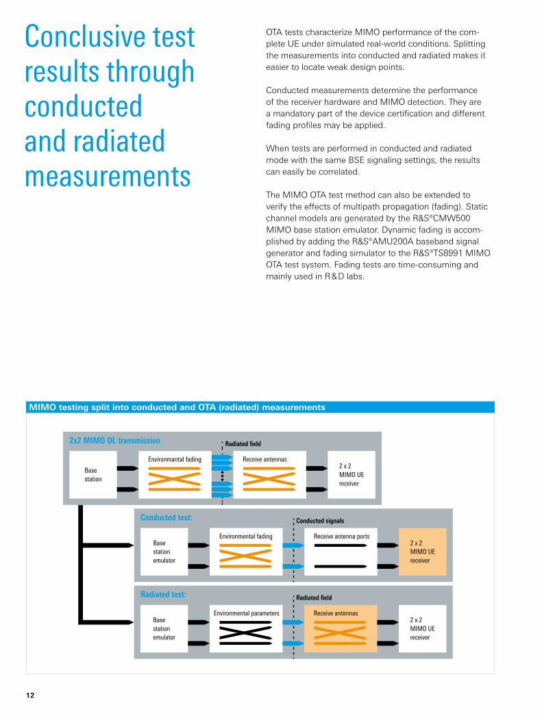
OTA tests characterize MIMO performance of the com-plete UE under simulated real-world conditions. Splitting the measurements into conducted and radiated makes it easier to locate weak design points.
Conducted measurements determine the performance of the receiver hardware and MIMO detection. They are a mandatory part of the device certification and different fading profiles may be applied.
When tests are performed in conducted and radiated mode with the same BSE signaling settings, the results can easily be correlated.
The MIMO OTA test method can also be extended to verify the effects of multipath propagation (fading). Static channel models are generated by the R&S®CMW500 MIMO base station emulator. Dynamic fading is accom-plished by adding the R&S®AMU200A baseband signal generator and fading simulator to the R&S®TS8991 MIMO OTA test system. Fading tests are time-consuming and mainly used in R & D labs.
MIMO testing split into conducted and OTA (radiated) measurements
•••
Basestationemulator
Environmental parameters Receive antennas2 x 2MIMO UEreceiver
Radiated test: Radiated field
Basestationemulator
Environmental fading Receive antenna ports2 x 2MIMO UEreceiver
Conducted test: Conducted signals
Basestation
Receive antennas2 x 2MIMO UEreceiver
2x2 MIMO DL transmission Radiated field
Environmantal fading

Rohde & Schwarz OTA performance measurements of MIMO-enabled devices 13
Automated measurements with ready-to-use test templates
Test procedure flexibilityWith the R&S®AMS32-K31 MIMO OTA option, users can customize the parameters of the test procedure, such as an arbitrary set of geometrical constellations and polarization cases or the base station emulator’s transmission modes.
Standard-specific templates includedA wide variety of test templates for all common wireless standards are available for the R&S®AMS32 option. The templates are ready to use without any programming. The individual test plan for a test run is easily configured using a menu-driven parametric setup (such as cellular band, channel list, power level).
Network operator test solutionThe R&S®TS8991 test system and R&S®AMS32 test software with the R&S®AMS32-K30 LTE OTA option for Verizon Wireless is the first available network-operator-specific test solution. It characterizes LTE MIMO devices in accordance with the over-the-air performance test plan published as part of the Verizon Wireless Open Develop-ment Initiative.
Result documentation made easyThe integrated report function of the R&S®AMS32 soft-ware collects all measured test data such as graphics and numerical results, test environments, EUT information and hardware setup in a single document. The report layout can be customized and the summary report file is stored in standard formats, e.g. XML or PDF.
OTA measurements – SISO and MIMOThe comprehensive R&S®AMS32 system software is based on the same software platform as the market-leading R&S®EMC32 solution.
R&S®AMS32 offers: ❙ Passive antenna measurements ❙ SISO OTA testing ❙ MIMO OTA measurements ❙ Calibration and analysis tools
It also supports assisted GPS testing with the popular and highly cost-effective R&S®AMS32-K28 A-GPS solution.
MIMO measurement mode of
R&S®AMS32 system software.

14
GlossaryTerm Explanation3GPP 3rd Generation Partnership Project
AoA Angle of arrival
BLER Block error rate
BSE Base station emulator
CDF Cumulative distribution function
CCDF Complementary cumulative distribution function
CTIA Cellular Telecommunications Industry Association
DL Downlink
EIS Effective isotropic sensitivity (single geometric point)
EUT Equipment under test
FOM Figure of merit
LTE Long term evolution
MCS Modulation and coding scheme
MIMO Multiple input multiple output
OLSM Open-loop spatial multiplexing
OTA Over the air
PDF Probability distribution function
SISO Single input single output
TD Transmit diversity
TIS Total isotropic sensitivity
TP Throughput
TRP Total radiated power
UE User equipment

Rohde & Schwarz OTA performance measurements of MIMO-enabled devices 15
Ordering information
Your local Rohde & Schwarz expert will help you determine the optimum solution for your requirements.To find your nearest Rohde & Schwarz representative, visitwww.sales.rohde-schwarz.com
Designation Type Order No.OTA Performance Test System R&S®TS8991 1119.4309.02
Over-The-Air (OTA) Performance Measurement Software 1) R&S®AMS32 1508.6650.02
Option for R&S®AMS32 OTA Software: LTE ECC R&S®AMS32-K30 1508.6680.30
Option for R&S®AMS32 OTA Software: MIMO R&S®AMS32-K31 1508.6680.31
1) Project specific configuration required.
Phantom head on azimuth positioner simulates real operation of
user equipment (UE).

Certified Quality System
ISO 9001
R&S® is a registered trademark of Rohde & Schwarz GmbH & Co. KG
Trade names are trademarks of the owners | Printed in Germany (ch)
PD 5214.6545.92 | Version 01.00 | November 2011 | R&S®TS8991
Data without tolerance limits is not binding | Subject to change
©2011Rohde&SchwarzGmbH&Co. KG|81671München,Germany
About Rohde & SchwarzRohde & Schwarz is an independent group of companies specializing in electronics. It is a leading supplier of solu-tions in the fields of test and measurement, broadcasting, radiomonitoring and radiolocation, as well as secure communications. Established more than 75 years ago, Rohde & Schwarz has a global presence and a dedicated service network in over 70 countries. Company headquar-ters are in Munich, Germany.
Environmental commitment ❙ Energy-efficientproducts ❙ Continuous improvement in environmental sustainability ❙ ISO14001-certifiedenvironmentalmanagementsystem
Rohde & Schwarz GmbH & Co. KGwww.rohde-schwarz.com
Regional contact ❙ Europe, Africa, Middle East | +49 89 4129 12345 [email protected]
❙ North America | 1 888 TEST RSA (1 888 837 87 72) [email protected]
❙ Latin America | +1 410 910 79 88 [email protected]
❙ Asia/Pacific|+6565130488 [email protected]
❙ China | +86 800 810 8228/+86 400 650 5896 [email protected]
Service you can rely onJ Worldwide J Local and personalizedJ Customized and flexibleJ Uncompromising qualityJ Long-term dependability
5214654592