Embed Size (px)
Citation preview

SoS
dynamic software & engineering
ETK
optiSLangmultiPlas
ISSUE 2/2015
RDO-JOURNAL
Title Story // Bosch – fi rst key user of optiSLangMethods for optimization of air cooled surface topologiesoptiSLang v5Robust optimization of automotive suspension designsModel calibration for analyzing fi lm copperOptimization of valve geometries in the launcher Ariane 5

Editorial
Already in 2002, Dynardo’s fi rst key customer, Robert Bosch GmbH, started with initial parametric optimization and ro-bustness analysis using optiSLang to partially replace expen-sive hardware tests and to gain more product understanding.
Nowadays, our customers face an ever increasing complexity in product development which demands new effective simu-lation based approaches regarding quality aspects, robust-ness, production cost and time to market. The variety of man-ufacturing, assembly and condition has to be considered with suffi cient reliability under scattering environmental circum-stances. In order to cope with these requirements and to stay competitive on the international market, the engineer has attractive options at a comparatively low cost level by using the advantages of parametric simulation based RDO. It can be used to better understand the design by conducting a sensi-tivity analysis, to improve the design by using methods of op-timization and to validate the product quality by conducting a stochastic analysis. If CAE-based optimization and robustness evaluation are combined, we are speaking of Robust Design Optimization (RDO), which may also be called “Design for Six Sigma” (DFSS) or just “Robust Design” (RD).
In this process, it is crucial to connect parametric CAD and CAE to one parametric multi-physics simulation workfl ow with provided interfaces and a fl exible integration of differ-ent CAX environments. Then, connected with state-of-the-art algorithmic implementations, best practice defaults and wizard-guided procedures, an improvement of the product combined with quality assurance will be achieved.
The openness of Dynardo’s software optiSLang regarding parametric modeling environments as well as the auto-mated algorithmic modules of sensitivity analysis, multi-objective optimization and robustness evaluation provide the user with a maximum amount of potential for product improvement, process traceability and quality monitoring. Furthermore, optiSLang provides unique algorithms like the Metamodel of Optimal Prognosis (MOP) to determine the most important correlations between parameter input vari-ation and output results. This can be used as a meta-model for CAE-calculations in optimization procedures or robust-ness evaluation. The Coeffi cient of Prognosis (CoP) assures a predictable and reliable forecast of response variation and minimizes necessary solver calls.
In this edition, we would like to share the practical experience of our long-term customer Robert Bosch GmbH regarding the application of CAE-based RDO and the process implementa-tion of optiSLang. For more than 13 years, Bosch has been gaining an extensive knowledge in parametric optimization and stochastic analysis in virtual product development.
Apart from that, we again have selected case studies and customer stories concerning CAE-based Robust Design Opti-mization (RDO) applied in different industries.
I hope you will enjoy reading our magazine.
Yours sincerely
Johannes WillManaging Director DYNARDO GmbH
Weimar, October 2015
CONTENT 2 // TITLE STORY // OPTISLANG & RDO AT BOSCHRobert Bosch GmbH – fi rst key user of optiSLang
5 // BOSCH CUSTOMER STORY // ELECTRICAL ENGINEERINGMethods for optimization of air cooled surface topologies
8 // DYNARDO GMBH // SOFTWARE & DEVELOPMENToptiSLang v5
10 // CUSTOMER STORY // AUTOMOTIVE ENGINEERING Robust automotive suspension design using multi-objective optimization
16 // CUSTOMER STORY // ELECTRICAL ENGINEERING Optimization of model calibration for analyzing the behavior of fi lm copper
18 // CUSTOMER STORY // AEROSPACE INDUSTRY Optimization of valve geometries in the engine system of the Ariane 5
CAE-BASED RDO – AN ESSENTIAL PART OF COMPETITIVE PRODUCT DEVELOPMENT
Johannes WillManaging Director DYNARDO

Title Story // optislang & RDO at Robert Bosch GmbH
RDO-JOURNAL // ISSUE 2/2015 32
For more than 13 years of application, Bosch has been gaining an extensive experience of parametric optimization and stochastic analysis in virtual product development.
ROBERT BOSCH GMBH – FIRST KEY USER OF OPTISLANG
TITLE STORY // OPTISLANG & RDO AT BOSCH
Methods of CAE-based optimization and stochastic analysis have become key technologies in parametric simulation. Thus, designs can be already tested and improved under the con-sideration of scattering properties in the development phase in order to reduce the number of hard ware tests and time to market. Beside parametric CAE models, state-of-the-art algo-rithms, a high degree of automation and the availability of powerful hardware is a crucial requirement for a successful implementation of parametric optimization in CAE - processes.
In an interview given in 2004 (fi rst published in Simulation, 1/2004, page 78-79), Roland Schirrmacher (Corporate Sec-tor Research and Advance Engineering at Bosch) defi ned the requirements for CAE software as follows:
The most important criteria are the functionality and the fea-tures of the software followed by operating stability and user-friendliness. The complex industrial tasks require sophisticated methods using various approaches and achieving a signifi -cantly improved design with a minimum number of iterations.
At that time, Mr. Schirrmacher said about the application of optiSLang at Bosch:
In the fi eld of optimization, all methods implemented in op-tiSLang have been used successfully. As a fi rst step, a Design of Experiment (DoE) scheme is often generated to obtain initial information about component behavior from the response surfaces and to possibly eliminate unnecessary parameters. Utilizing these response surfaces, several improved designs are simulated afterwards by using gradient or evolutionary strat-egies. These can be taken as starting designs for a gradient-based optimization or as an initial population. This procedure has proven especially successful in an optimization using im-proper initial designs and under highly nonlinear conditions.
The graphical user interface of optiSLang is designed intui-tively and does not make high demands on the user provid-ing a step by step procedure of necessary input. The most complex part of the task defi nition is to build the parameter-ized model and to connect all programs or commands associ-ated to the workfl ow in one script. Bosch insisted to reference only this script during the development of optiSLang in order to guarantee the fl exibility for a variety of tasks.
Robert Bosch GmbH was the fi rst key customer in the in-dustrial use of optiSLang. The application started in 2002
as a research project and since has been developed over the years to an integral part in the virtual development process at Bosch. Applications include et al.:
• Simulation of loads and durability regarding electric drives in vehicles
• Simulation of the behavior of design elements exposed to thermal loads
• Reliability analysis • Realistic simulations of dynamic designs including mate-
rial models • Robustness evaluations toward scatter, such as manufac-
turing tolerances • Parameter identifi cation for the calibration of material
models • Optimization and robustness evaluation during the sim-
ulation of mechanical systems • Virtual product design • Sensitivity analysis of product life based on parametric
models • Multiobjective optimizations
In May 2015, Dynardo visited Mr. Schirrmacher and two of his colleagues in Stuttgart to take stock again regarding the use of optiSLang and the cooperation between Dynardo and Bosch.
Since when have you been using optiSLang in the product development process at Robert Bosch GmbH?The test phase of optiSLang started in 2002 with basic research and setting up software tools like ETK, optiPlug for ANSYS or Optiqus-Plugin for coupling parametric CATIA-Models with Abaqus/CAE. After this phase was successfully fi nished, we be-gan to implement the software into the product development process at Bosch. The fi rst fi elds of application dealt with injec-tor development and power tools. Meanwhile, optiSLang has been utilized in almost all business units of Bosch.
What were the reasons for Bosch to decide in favor of optiSLang?optiSLang was chosen out of three software products after a benchmark in the automotive industry in 2001. At that time, a major reason was that optiSLang had already imple-mented all essential methods, for example, Design of Experi-ment, meta-models or procedures of optimization, robust-ness and reliability. This also applied to the design variable types which could be processed ranging from binary to real and integers. Another reason for our decision was that Dy-nardo allowed us to directly infl uence the software develop-ment combined with a fast and service-oriented support. The contact with the development department and the resulting short paths of communication are still reasons for the close and successful cooperation. We also appreciate the fl exible and open licensing models provided by the company.
What are the most important applications of optiSLang at Bosch?
The fi rst fi elds of application were in structural mechanics combined with the CAE programs Abaqus and ANSYS. Later projects were added in electrodynamics, fl uid dynamics and thermodynamics. In recent years, optiSLang has been increasingly used regarding multibody simulation models as well as system models from Matlab or AMESim. Besides the application to product development, optiSLang is often used for parameter identifi cation of material properties. Also
in the advanced development, optiSLang workfl ows are im-plemented for model development, pre-standardization by tolerance analysis, functional analysis as well as robustness evaluation. In the design of electric motors, optiSLang is part of the standard process for sensitivity analysis, optimization and robustness evaluation of, for example, eccentricity, brush running or other motor characteristics. In collaboration with the manufacturing, investigations of production tolerances along with evaluations and data analyses regarding correla-tions and parameter dependencies are conducted.
Which methods and workfl ows are used most intensively?The most common applications are sensitivity analyses and robustness evaluations. optiSLang is also increasingly used for the generation of meta-models in order to effi ciently de-scribe the phenomena occurring in complex and extensive simulation tasks, to use them in system simulation as well as to draw conclusions for the optimization. During the ad-vanced development process, sensitivity analyses regarding scattering parameters are conducted for a better product understanding and for setting the base to conduct multi-objective optimizations.
What are the main benefi ts from the use of optiSLang in the virtual product development at Bosch?By using optiSLang, we obtain a much better product under-standing regarding the product robustness, sensi-tivities as well as the potentials for optimizations and their boundaries. Thus, we can specifi cally improve the product performance during the development stage to come up with an already optimized initial
Start window of optiSLang 3

optiSLang is used at Robert Bosch GmbH for optimizing the surface topology of heat sink geometries to enhance their convective heat transfer to the ambient air fl ow.
METHODS FOR OPTIMIZATION OF AIR COOLED SURFACE TOPOLOGIES
BOSCH CUSTOMER STORY // ELECTRICAL ENGINEERING
Title Story // optislang & RDO at Robert Bosch GmbH
RDO-JOURNAL // ISSUE 2/2015 54
sample saving a lot of time and money in prototyping. In com-plex multi-domain application, optiSLang also fi nds optimal designs which have not been found by experts. By taking into account scattering effects, which is hardly or not at all possible in hardware tests, we can determine and evaluate product ro-bustness and limiting samples a lot more accurately and faster. The saving of extensive tests regarding product life and durabil-ity especially accelerates our development process considerably.
How important are the issues of process automation and integration? Due to the importance of these issues, there has been a coop-eration to improve process automation and integration ca-pabilities in optiSLang between Bosch and Dynardo for quite some time. The main benefi ts are the control of system com-plexity and the standardization of the workfl ow manage-ment. Here, the intention at Bosch has always been to have a one-software-solution for all the different CAX processes. The multi-functionality of optiSLang has fulfi lled this expec-tation. The aim is to generate interfaces for process integra-tion with little programming effort. The implementation of simple standard templates must be possible without special knowledge. This is the only way to cope with the rising de-mand for simulations by the same human resources.
What other areas of application in the product develop-ment at Bosch can you imagine in the future? In the future, we consider improvements in the visualiza-tion of correlations and results, for example, Pareto fronts in multi-objective optimizations, as an expandable applica-tion of optiSLang. In addition, the software will be increas-ingly used in sensitivity analyses of signals. Also the issue of meta-models is of crucial importance in order to obtain greater effi ciency and opportunities in the approximation and evaluation of, for example, several operating points or characteristics. These meta-models can be stored as basis product knowledge for further modeling.
How important is the issue of Robust Design Optimization at Bosch?
Robustness of designs is a very important issue for Bosch. Proving the design robustness during virtual prototyping is one of the most important applications of optiSLang, be-cause the optimal nominal design does not represent an optimum in reality. However, the automatic combination with optimization procedures make high demands on the parametric modelling process. Today it is only applicable for some modules but not for the whole CAX portfolio. The quali-fi cation of parametric modeling and the automation of CAX processes as requirements for a more frequently use of Ro-bust Design Optimization will be an important point on the agenda for the next years.
Which “bottlenecks” appear during the implementation of robust design optimization with optiSLang today?We are constantly working on expanding and assessing our product knowledge regarding scatter conditions in manufac-turing, material properties and environmental circumstances. In this process, a close cooperation between development and manufacturing departments plays a major role. Respectively, the interfaces between CAD and CAE process parameters and the transfer of geometric tolerances must be further improved and optimized. Another key point is the availability of effi cient and powerful hardware in the CAE process in order to keep the overall response time as moderate as possible. In this con-text, it is still a major challenge to handle the complexity of 3D parametric CAE modeling. This includes constraints, loads and contact as well as the associated model size taking into account meta-models and a high number of parameters. Here, the license models of all commercial CAE codes used must en-sure a simple availability of parallel computing and processes, storage management as well as bundling of calculations.
What can Dynardo do to overcome these obstacles? In this context, we expect from Dynardo further development and improvement of automatic generation of best possible meta-models out of simulation or measurement data bases as a very important strategy of reducing the complexity of CAE-based simulations. In order to minimize the manual transfer of parameters or processes, the approach of generating transfer-able, reusable template structures inside optiSLang should be expanded. Here, of course, the compatibility between platforms and interfaces plays a crucial role. Also, the increased complex-ity of post-processing much more parameters, responses and objectives must be constantly monitored regarding the preven-tion of a decline in the software’s performance capacity.
Author // H. Schwarz (Dynardo GmbH)
The interview was given on Mai 13th in 2015 in Stuttgart by:Dipl.-Ing. Roland Schirrmacher Corporate Sector Research and Advance Engineering Dipl.-Ing. Henning KreschelDiesel Systems, Common Rail Injector DevelopmentDr.-Ing. Olaf SchönrockAdvanced Development
MotivationThe thermal performance requirements of air cooled elec-tronic control units (ECUs) increase continuously due to the growing extent of implemented functionality and thus higher power loss density and the trend of miniaturization. To meet these targets, it is mandatory to enhance the con-vective heat transfer to the ambient air fl ow by means of optimizing the surface topology of heat sink geometries.
IntroductionIn order to quantify the cooler performance for a given power loss P
v and air fl ow, either the cooler temperature or
the derived scalar quantity Thermal Resistance “Rth
” is usu-ally chosen as a primary output variable:
with the heater surface temperature Tsurf
and the constant ambient temperature T
amb. Furthermore, the objective ma-
terial volume of the heat sink as an indirect estimation
for the manufacturing costs is of relevance and used as secondary output variable. It is not unusual that optimal cooler design and low cooler mass are in confl ict with each other, therefore, a multi-objective optimization has to be performed in order to compromise for a design.
RealizationIn order to tackle this task, several different approaches were implemented in both, optiSLang and optiSLang in-side ANSYS Workbench utilizing different computational fl uid dynamics programs (CFD), namely scStream (Cradle), FloEFD (Mentor Graphics) and CFX (ANSYS) as it can be seen in Fig. 1 (see next page). These procedures all have their own benefi ts and draw backs. In standalone optiSLang for example any scriptable software can be used as shown in Fig. 1a) - c) (see next page). The method shown in Fig. 1b) (see next page) even relies on implementing Excel with its powerful Visual Basic utilities in order to control calcula-tions, simulations and several batch scriptable programs. In this case, VBA, VBS, windows batch, scStream, ANSYS APDL and Python was used.
Graphical user interface optiSLang 4
Electrical Engineering Electrical Engineering
RDO-JOURNAL // ISSUE 2/2015 76
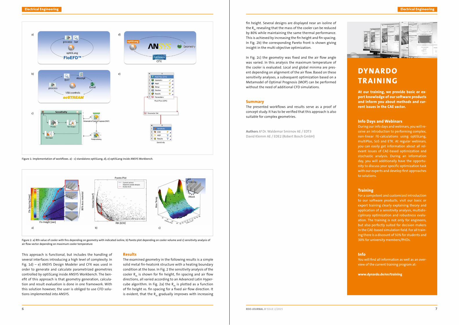
This approach is functional, but includes the handling of several interfaces introducing a high level of complexity. In Fig. 1d) – e) ANSYS Design Modeler and CFX was used in order to generate and calculate parametrized geometries controlled by optiSLang inside ANSYS Workbench. The ben-efi t of this approach is that geometry generation, calcula-tion and result evaluation is done in one framework. With this solution however, the user is obliged to use CFD solu-tions implemented into ANSYS.
ResultsThe examined geometry in the following results is a simple solid metal fi n-heatsink structure with a heating boundary condition at the base. In Fig. 2 the sensitivity analysis of the cooler R
th is shown for fi n height, fi n spacing and air fl ow
directions, all varied according to an Advanced Latin Hyper-cube algorithm. In Fig. 2a) the R
th is plotted as a function
of fi n height vs. fi n spacing for a fi xed air fl ow direction. It is evident, that the R
th gradually improves with increasing
fi n height. Several designs are displayed near an isoline of the R
th revealing that the mass of the cooler can be reduced
by 80% while maintaining the same thermal performance. This is achieved by increasing the fi n height and fi n spacing. In Fig. 2b) the corresponding Pareto front is shown giving insight in the multi objective optimization.
In Fig. 2c) the geometry was fi xed and the air fl ow angle was varied. In this analysis the maximum temperature of the cooler is evaluated. Local and global minima are pres-ent depending on alignment of the air fl ow. Based on these sensitivity analyses, a subsequent optimization based on a Metamodel of Optimal Prognosis (MOP) can be performed without the need of additional CFD simulations.
SummaryThe presented workfl ows and results serve as a proof of concept study. It has to be verifi ed that this approach is also suitable for complex geometries.
Authors // Dr. Waldemar Smirnov AE / EDT3David Klemm AE / EDE2 (Robert Bosch GmbH)
Figure 1: Implementation of workfl ows. a) - c) standalone optiSLang, d), e) optiSLang inside ANSYS Workbench.
Figure 2: a) Rth value of cooler with fi ns depending on geometry with indicated isoline, b) Pareto plot depending on cooler volume and c) sensitivity analysis of
air fl ow vector depending on maximum cooler temperature
a)
b)
c)
d)
e) DYNARDOTR AI N I NGAt our training, we provide basic or ex-pert knowledge of our software products and inform you about methods and cur-rent issues in the CAE sector.
Info Days and WebinarsDuring our info days and webinars, you will re-ceive an introduction to performing complex, non-linear FE-calculations using optiSLang, multiPlas, SoS and ETK. At regular webinars, you can easily get information about all rel-evant issues of CAE-based optimization and stochastic analysis. During an information day, you will additionally have the opportu-nity to discuss your specifi c optimization task with our experts and develop fi rst approaches to solutions.
TrainingFor a competent and customized introduction to our software products, visit our basic or expert training clearly explaining theory and application of a sensitivity analysis, multidis-ciplinary optimization and robustness evalu-ation. The training is not only for engineers, but also perfectly suited for decision makers in the CAE-based simulation fi eld. For all train-ing there is a discount of 50% for students and 30% for university members/PHDs.
InfoYou will fi nd all information as well as an over-view of the current training program at:
www.dynardo.de/en/training
a) b) c)

© 2002-2015 Dynardo GmbH. All rights reserved.
5
From expert tool to standard application – CAE-based Robust Design Optimization (RDO) with optiSLang in industrial product development.
OPTISLANG V5
DYNARDO GMBH // SOFTWARE & DEVELOPMENT
Dynardo GmbH // Software & Development
RDO-JOURNAL // ISSUE 2/2015 98
Optimization in virtual prototyping aims at achieving the best possible product features with minimal resource con-sumption. Here, product optimization often approaches lim-its of tolerable load or deformation. Guaranteeing robust-ness against scatter is increasingly becoming a focus in the development process. With the help of CAE-based Robust Design Optimization (RDO) and optiSLang, the robustness can be analyzed and proved against scattering material pa-rameters, geometry changes or environmental conditions. Innovative methods as well as a simple and intuitive user interface are crucial for a successful implementation of CAE-based product optimization in order to gain:
• Time-effi ciency by Automatization • Higher quality in V-PDP by standardization • Assurance of innovation by individualization of fl exible
fl ows, combination of CAx tools and algorithms • Extensive usage of expert know how by collaborative work
optiSLang‘s effi cient sampling and optimization methods allow to solve even highly complex, non-linear tasks. Meta-models with optimal prognosis quality are automatically generated taking into account a maximum of potentially
affecting variables while minimizing CAE solver runs. For the best possible user friendliness in building up a CAE process chain, the operator is supported by predefi ned and task-oriented workfl ows. An expert knowledge on stochas-tic or statistical analysis is not required anymore to routine-ly use RDO in industrial product development.
PostprocessingOne of the most important parts in optiSLang is its post-processing. Based on requests from our customers, Dynar-do’s development team widely enriched the functionality in version 5. The access to all plots in all standard modes is now possible, e.g. for approximations, optimizations or statistics. Therewith, users are provided with a high fl exibil-ity when exploring the data of the parametric studies. For a better monitoring during a running analysis, e.g. conduct-ing an optimization, the automatic update of the plots can be chosen now. Thus, for instance, the convergence of the optimizer can be directly tracked while all plots keep their position and size. Furthermore, the postprocessor has been opened for customization. Besides the standard modes of approximation, optimization and statistics, users now can
defi ne their own standardized way to explore the data. This includes, for example, which plots should be displayed when the postprocessing opens or which designs should be highlighted. Additionally, the export of plots as pictures (png, jpg etc.) and, thus, the examination and report gen-eration can be automatized and standardized.
MOP®
The technology using DOE, the Metamodel of Optimal Prog-nosis (MOP)® and the Coeffi cient of Prognosis (CoP)® is one key to a successful performance of parametric studies. Dynar-do’s development and research teams continuously work to improve this technology in order to provide more possibilities for design understanding. Based on a research project with Fraunhofer ITWM, the MOP algorithm was re-implemented to achieve an optimized performance in searching for the best meta-model and for its use in an MOP-solver. Thereby, it is, for example, possible to parallelize the search. Thus, the time to create and search the MOP can be divided by the number of CPUs. Additionally, because of this gained optimized perfor-mance, two new meta-model types could be added to the list of options: Kriging and Anisotropic Kriging.
Following the motto “from expert tool to standard applica-tion”, the user is now supported by “Automatic settings” in the MOP dialog. Therein, users have just a few clearly ar-ranged settings to generate the MOP analysis. Those provide proven default settings for the most common applications. Detailed settings are still possible in the advanced section.
Robustness wizardCAx based tolerance analysis needs algorithms covering a range from 1 to 8 sigma. Based on Dynardo’s tradition and 30 years of experience, those have been provided since the fi rst versions of optiSLang. This includes algorithms for all sigma levels as well as the proof of quality of an optimized design in an RDO fl ow.
As users know from the optimization wizard, based on un-derlying information about the task, the robustness wizard now helps to select the suitable algorithm. All algorithms for variance based and reliability based analysis are now avail-able in optiSLang and in optiSLang inside ANSYS. By the help of the decision helpers a detailed expert knowledge is not needed to set up a Design for Six Sigma project.
Workfl owsBesides the wizard based and best practice set up of RDO tasks, the convenience to create very complex fl ows was also increased in version 5. By the enlarged functionality of data-mining, it is now possible, for example, to quickly build optimization workfl ows which consider the perfor-mance of multiple operational points (sweep) or larger
grids (n-dimensional). Quick geometry pre-checks help to decide whether the meshing and solving is appropriate or not. Thus, it is possible to defi ne sub-fl ows which only start an evaluation if a precondition is fulfi lled. A lot of unneces-sary analysis time can be saved and the total execution can be extremely accelerated.
OpennessoptiSLang supports both the parametric and non-parametric interfacing to almost any CAx tool and fulfi lls the require-ments of running in batch. Algorithmic building blocks are provided for an automatized and standardized RDO in virtual product development. Over the last years, a lot of successful implementations of optiSLang into company solutions have been realized including MS Excel interfaces as well as custom or even web applications. The openness provides the cus-tomers with the ability to use their own integration nodes, algorithms and meta-models as plug-ins in optiSLang fl ows.
Author // David Schneider | Product Manager optiSLang (Dynardo GmbH)
Approximation postprocessing in optiSLang v5
Wizard for robustness and reliability evaluation in optiSLang v5

A Robust Design Optimization (RDO) approach with optiSLang is used to implement further improvements in car suspension design with respect to model transferability and a wide spectrum of load variations.
ROBUST AUTOMOTIVE SUSPENSION DESIGN USING MULTI-OBJECTIVE OPTIMIZATION
CUSTOMER STORY // AUTOMOTIVE ENGINEERING
Automotive Engineering
RDO-JOURNAL // ISSUE 2/2015 1110
IntroductionFor decades, automotive experts have gained a profound level of knowledge in the fi eld of conventional suspension design leading to a high degree of maturity of current car suspensions. To carry out further improvements, it is inevita-ble to increase complexity by introducing more sophisticated designs. In parallel, the needs with respect to robustness are dramatically increasing due to a still growing number of de-rivatives on the one hand and a wider spectrum of wheel load variations by introducing electric batteries for plug-in and pure electrically driven cars on the other hand. Under these circumstances, optimal solutions are hard to fi nd by human search. Computer-based optimization used in the digital phase of suspension development may help to improve in-sight into the system and to implement better designs. Be-sides optimizing individual car suspensions, however, it is also desirable to ensure consistent ride and handling behav-ior for a whole car segment including different engines, extra equipment, plug-in batteries and customer loading. Thus, a suspension system should be designed so that it can be used in several derivatives such as sedans, station wagons, coupes, etc. This may be achieved by using RDO as it will be shown by an approach based on optiSLang.
Robust Design OptimizationGenerally, RDO is an optimization performed under con-sideration of uncertainties. Typical tasks are to optimize a given objective while fulfi lling constraints with a specifi ed safety margin or minimizing the variance of responses with respect to uncertainties.
Because robustness measures (variances and mean values) are used in the presented optimization loop, the procedure is considered as an integrated variance based RDO. For each design generated by the optimization algorithm, mean val-ue and variance need to be estimated. Because this proce-dure needs a vast amount of CPU-time for expensive direct function evaluations, an effi cient design evaluation process using an adaptive Response Surface approach is needed if time-consuming simulations are involved.
Adaptive Response Surface Based RDOAs mentioned above, the Response Surface Method (RSM) offers an opportunity to minimize the amount of CPU-time needed for the RDO process. Here, an aRSM based multi-objective RDO is used and explained in the following.
The goal is to optimize a system in terms of minimizing mean and variance of an objective function with a given set of design parameters between some upper and lower bounds and with normally distributed stochastic variables representing uncertainties. The solution process consists of two parts: an initial sampling and the main RDO loop con-sisting of different process steps, see Figure 1.
In the fi rst step, a predefi ned number of design points are gen-erated in the design space of the optimization. For every point in the optimization space, a sampling within the space of uncertainties is done. To avoid purely distributed inputs, par-ticularly for a small amount of samples, advanced Latin Hyper-cube Sampling (aLHS) is used for initial and uncertainty sam-pling. The resulting set of sample points in the design space of optimization acts as a set of support points for generating response surfaces for mean and variance estimation. These robustness measures are evaluated by solving the sampling in uncertainty space of every support point. In the fi rst step of the main RDO loop, response surfaces are built up from the actual set of support points and associated response values. To build up the response surface, the Metamodel of Optimized Progno-sis (MOP) is used. Briefl y said, MOP is an automatic approach which searches for the best subspace of important optimiza-tion parameters and the best response surface approximation
for a given dataset with respect to a specifi c validation meth-od. For the developed process, parameter fi ltering is disabled and the MOP is only used for metamodeling. Polynomial least squares approximation, moving least squares and ordinary Kriging have been currently implemented in optiSLang. After generating the response surface, the optimization problem is solved on the response surface. A global evolutionary optimi-zation algorithm based on the Strength Pareto Evolutionary Algorithm (SPEA2) is used. The algorithm generates a Pareto-front of optimal compromises between low mean value and low variance dominating the remaining designs. The result of the optimization is a set of non-dominated compromise de-signs and a remaining set of dominated designs.
In the next step, proper sample points for the adaption of the response surfaces have to be selected, which is briefl y explained in the following. At fi rst, minimum distances be-tween non-dominated designs and all points of the actual set of support points are calculated. The design with the maximum distance is then chosen as a new potential RS support point and removed from the set of non-dominated designs. In order to prevent the selection of new support points lying too close to others or being even identical to an already existing support point, a characteristic distance cri-terion is introduced which needs to be fulfi lled. If the char-acteristic distance criterion cannot be satisfi ed by enough Pareto optimal designs, the set of non-dominated designs is extended by the set of dominated designs, forcing the algorithm to globally update the meta-model. This process repeats itself until a predefi ned number of new support points are found. After updating the set of support points, design evaluation is performed for all new support points. Based on the new set, response surfaces are updated and the RDO loop in Figure 1 repeats itself until a maximum number of iterations or a convergence criterion is fulfi lled.
To check for convergence, approximation quality of the new support points is assessed in the criterion space, mean-ing that the relative differences between objective values gained from response surfaces and originally evaluated values are assessed: if this error rate is smaller than a pre-defi ned error tolerance, the algorithm is assumed to be con-verged and the RDO procedure fi nishes.
Implementation in optiSLangThe proposed process is implemented in the commercial optimization tool optiSLang by combining the described al-gorithms with existing process nodes out of the optiSLang library. The implementation of the RDO process in optiSLang is shown in Figure 2 (see next page), where the different process nodes are numbered and will be explained in the following.
The fi rst node in the blue box (1) in Figure 2 (see next page) is a sensitivity node used for initial sampling. Here, a pre-defi ned number of sample points are generated and evalu-
Fig. 1: Flow chart of the adaptive response surface based RDO
RDO Loop
Convergence criteria‘sreached?
Yes
No

Automotive EngineeringAutomotive Engineering
RDO-JOURNAL // ISSUE 2/2015 1312
ated to be used as support points later. In order to determine robustness measures, a nested robustness analysis is per-formed for each design generated by the sensitivity node as shown in Figure 3.
The results are stored in a single fi le which is relocated to a specifi ed folder by the second node. This is done by a simple script written in Python-code which can be directly execut-ed in optiSLang by using the Python integration node.
In the fi rst step of the main RDO loop (see the green dashed box 2.1), response surfaces are built up from the actual set of support points by using the MOP node. To get the set of ac-tual support points, the MOP node reads the fi le mentioned above that is stored in a standardized location. Again, as ex-plained for the sensitivity node, the MOP node is only used for metamodeling, meaning that fi lters and post processing are deactivated. After generating the metamodels, the multi-objective optimization problem is solved on the response surfaces via the EA node shown in the red dashed box (2.2). In the next step, proper sample points for the adaption of the response surfaces are selected, which is done by a script executed in the Python node in the yellow dashed box (2.3). Evaluation of the new support points and check for conver-gence is done by the nodes in the purple dashed box (2.4). The fi rst node, a sensitivity node, acts similarly to the node used for initial sampling in the blue box (1). Here, the chosen points are evaluated by using the nested robustness analysis. The last node then appends the evaluated designs to the set
of support points. It checks for con-vergence and stores the new set of support points to the standardized lo-cation as mentioned above. Now, the next iteration is performed starting with the metamodeling of the MOP node. This process repeats itself until one of the stop criteria defi ned above is fulfi lled.
Application to Suspension DesignThe proposed method is applied to Ro-bust Design Optimization of a suspen-sion of a full vehicle model. The vehi-cle, a luxury passenger car, is modeled as a multibody system (MBS) with 112 rigid bodies and 111 degrees of free-dom (DOF). Model components are suspension links, wheel carriers, bush-ings, spherical joints, springs, dampers, wheels, tires, steering system, as well as subframe at the rear axle and the main body. Two different comfort ori-ented load cases are investigated. The main goal is to fi nd a bushing setup
which has the best robust performance with respect to the specifi c objectives and uncertainties. The uncertainties shall emulate different car derivatives which have the same track width, wheelbase and kinematic hard points, but different mass and size.
Design GoalDesign goal is to minimize the oscillation intensities of two typical driving maneuvers. The fi rst load case is called axle tramp which is a coupled oscillation between wheel and axle appearing while a car is accelerating or braking. In this article, only the axle tramp during braking is investigated. Depending on axle kinematics, the wheel moves backwards and upwards due to the applied braking force which leads to a loss of road contact and, thus, a reduction of the fric-tion force on the tire. This, however, lets the wheel swing back gaining more road contact again. Repetition results in the oscillation are illustrated in Figure 4. The most sensitive parameters for this scenario are the tire mass and stiffness as well as the bushing stiffness and damping where a certain amount of damping should be realized in particular.
To get a reproducible axle tramp behavior in the simula-tion, an initial vertical force impulse is applied to the rear wheels while the car is braking. The resulting longitudinal and vertical accelerations of the rear wheels in the time-domain are squared, integrated, normalized to a reference car and chosen e.g. as characteristic response criterion f
2 to
be minimized, see Figure 5.
In the second load case, the vehicle is driving with constant speed on a straight road while a single step-shaped roadway excitation occurs at the rear axle. Here, the acceleration of the driver’s seat in the opposite driving direction is investigated in the time-domain and transformed to criteria f
5 similarly to f
2,
which should be minimized, see Figure 6.
The fi rst acceleration peak can especially be recognized by passengers and, therefore, is of particular interest. To mini-mize the seat acceleration in the x-direction, the axles should provide enough longitudinal compliance and little damping.
For each of the altogether fi ve response criteria, mean value as well as variance are calculated, normalized with respect to a reference car and partly summed up to fi nally achieve two objectives for each load case. The different needs of both load cases regarding stiffness and damping should lead to compromised bushing setups forming a Pareto-front. These tradeoffs are hard to fi nd by human search which is why the proposed computer based optimization procedure is used.
Design ParametersThe stiffness and damping characteristics of the suspension bushings are chosen as design parameters where the bush-
ings are represented by a Kelvin-Voigt (KV) model as shown in Figure 7 (see next page). This model is limited in terms of approximating real bushing behavior, but it only needs two
Fig. 2: Implementation of the proposed method in optiSLang
Fig. 3: Sensitivity analysis with nested robustness analysis
Fig. 4: Schematic tire movement during tramp oscillation
Fig. 5: Schematic representation of one of the axle tramp responses (green curve) for the rear left wheel acceleration in x-direction (red curve)
Fig. 6: Schematic representation of the obstacle crossing response (green curve) for the driver’s seat acceleration in x-direction (red curve)

Automotive EngineeringAutomotive Engineering
RDO-JOURNAL // ISSUE 2/2015 1514
parameters which is effi cient. The main drawback of the model is the incapability of reproducing the real amplitude and frequency dependencies of rubber material used for ve-hicle bushings. To overcome this lack of approximation qual-ity, the KV model is parametrized to match the real bushing behavior only for a specifi c excitation frequency. This has been possible since the two considered load cases, i.e. axle tramp and free vibration after obstacle crossing, have well defi ned excitation frequencies. Briefl y said, dynamic stiffness cdyn and loss angle φ are calculated from design variables and converted to specifi c model parameters c and d, see Figure 7. In total, the vehicle model has 10 bushings where here only
translational bushing characteristics are changed. Cdyn and φ for each coor-dinate direction of each bushing ac-cumulates up to 60 parameters that may be considered. To minimize the amount of design parameters, a sen-sitivity analysis was performed result-ing in only 11 important parameters which are varied between predefi ned bounds. The associated bushings and their individual coordinate systems K1 to K4 are visualized in Figure 8.
UncertaintiesA passenger car underlies several uncertainties. In this article, the scatter of mass properties of load-ing and bodies is investigated ac-cording to Figure 9. More precisely, the variation of passenger numbers, fuel level, boot loading, extra equip-ment, engine and battery type are taken into account where positions are assumed to be given. Due to the lack of statistics for the masses de-scribed above, they are assumed to be normally distributed within given ranges and independent. For sam-pling purposes, a truncated standard normal distribution is used for each parameter and generated with aLHS for predefi ned bounds.
Optimization ResultsThe RDO is performed subjected to design objectives, normalized design parameters and uncertainties. For the evaluation of robustness mea-sures, a sample size of 20 is used for uncertainties. The initial set contains 30 support points. In each iteration, 5 new support points are added to im-prove the RS. The SPEA2 performs an optimization on the RS with a maxi-
mum of 150 generations using 20 new individuals in each generation. The RDO procedure is limited to 40 adaptions of the RS resulting in a maximum of (30+40×5)×20=4600 original design evaluations. While running 10 simulations in parallel, the overall RDO took 6 days and 9 hours until it converged after only 38 adaption iterations. The evaluated support points are shown in Figure 10.
It is clearly visible that all criteria improve simultaneously resulting in a rather narrow Pareto-front which indicates that mean objectives are not as contradicting as assumed. Nevertheless, both criteria could be enhanced with respect
Fig. 7: Schematic bushing parameterization process
Fig. 9: Sources of uncertainties and representation within the MBD model
Fig. 8: Side (a) and top view (b) of investigated rear axle with wheel carrier (grey), linkages (black), bush-
ings (white circles) and subframe (gray dashed)
to the reference vehicle setup and also the robustness seemed to be improved. For better visualization of the im-provement, histograms of two specifi c objectives of a Pare-to-optimal design lying on the knee of the front are shown in Figure 12. They have been compared to the reference set-up. It can be easily observed that mean value and variance are both signifi cantly improved. The corresponding accel-
erations determine f2 and f5 as the acceleration of the left
tire during tramp (Figure 11 top) and the driver’s seat after obstacle crossing (Figure 11 bottom) in x-direction. They confi rm the histogram information in Figure 12 in the time-domain. The large scatter in tire oscillation of the reference car during axle tramp can especially be observed.
ConclusionsThe article demonstrates an effi cient multi-objective robust design optimization procedure. The implementation of an adaptive response surface modeling strategy signifi cantly reduces computational effort compared to direct optimiza-tion. This is proven by optimizing a simple test function. An application of the proposed method to vehicle suspension design by using multibody system simulations and optiS-Lang is successfully performed. The optimization is done in terms of minimizing predefi ned accelerations measured throughout the load cases, which are axle tramp and single step-shaped roadway excitation for a given range of bush-ing stiffnesses as well as damping parameters under pres-ence of scattering vehicle masses. Although both load cases need contrary bushing characteristics, optimal compromise designs could be found where mean value and variance of the vehicles dynamical behavior are signifi cantly improved compared to a reference design.
Authors // P. T. Ubben , J. Haug (Daimler AG) / D. Bestle (Bran-denburgische Technische Universität Cottbus-Senftenberg)Source // www.dynardo.de/en/library
Fig. 10: 4D-Pareto plot of support points
Figure 11: Time plots of tire acceleration during tramp oscillation (top) and
driver’s seat acceleration after obstacle crossing (bottom) of optimal design
(red) and reference design (black)
Fig. 12: Frequency plot of objectives f2 (top) and f5 (bottom) for optimal
compromise design (red) and reference design (black)

Electrical Engineering
RDO-JOURNAL // ISSUE 2/2015 1716
optiSLang provides effective methods of parameter identifi cation to optimize the analysis of fi lm copper produced by Electro-Chemical Deposition (ECD) in the semiconductor industry.
OPTIMIZATION OF MODEL CALI BR ATION FOR ANALYZI NG TH E BEHAVIOR OF FI LM COPPER
CUSTOMER STORY // ELECTRICAL ENGINEERING
Optimization TaskMetallic thin fi lms often show a different physical behavior than bulk solids made of the same material. This requires the determination of new parameters of corresponding material models. Thin fi lm copper produced by ECD is widely used in the semiconductor industry because of its excellent electrical and thermal conductivity. The functionality of semiconductor products depends strongly on the mechanical performance of ECD-Cu under a broad temperature range. Therefore, the stress-strain response of this special copper is measured at different temperatures. The aim of the optimization was to match the reference signal (bow vs. time) from the experi-ment with the simulated signal from the FEM calculations.
MethodologyThe stress-strain response of this special copper is measured at different temperatures. The wafer curvature approach serves as a standard method. It measures the change of cur-vature radius due to mismatch in thermal extension coeffi -cients between the fi lm and substrate for a temperature pro-fi le. Silicon is often used as a substrate since its mechanical properties are defi ned and suffi ciently known.
In this example, an inelastic material model consisting of seven parameters was validated for ECD copper subjected to cyclic thermal loading (see Fig. 1).
The raw measured quantity was the curvature radius (see Fig. 2). It is usually used for the calculation of the bow (maximal defl ection of sample) and stress in the fi lm us-ing Stoney’s formula which is valid for the elastic and non-elastic range:
where 𝝈𝑪𝒖 describes the average fi lm stress in the direction of the length side of the strip, 𝒉𝑺𝒊 is the substrate thickness, 𝑹 is the radius of the curvature and 𝑬𝑺𝒊 is the Young‘s modu-lus of the substrate.
The measurement of the mechanical properties of the Cu-Si bimetallic strip was performed by a cyclical thermal exposure that is illustrated in Fig. 3 top. The corresponding measurement data deduced from the curvature of the substrate is shown in Fig. 3 bottom. Before running the calibration procedure, it had to be decided in which extent each parameter should be changed. For this purpose, gradients of the objective function were manually built as sensitivity measures using MS Excel. Even after achieving a satisfactory result with this method, it was not clear whether the parameter set could be further im-proved or not. For comparison, the optimization was also con-ducted with optiSLang applying the least squares approach.
Within one day, the automated optimization was fi nished after 284 runs of simulation. It could be seen that the agreement of the curves of the automated optimization was signifi cantly bet-ter than the agreement of the manual optimization (see Fig. 4).
Customer Benefi tsA “manual” validation was extremely time-consuming: it took about 3 weeks for 70 simulations. The problem was not necessarily the time needed for one run (it was less than 10 min), but the analysis of results and decision mak-ing how to change the parameter values in order to achieve a better calibration to the experimental results. With op-tiSLang, this procedure was optimized regarding time ef-fi ciency and result quality. An additional advantage of us-ing optiSLang was the possibility to repeat the parameter fi tting, for example, in the case if some model parameters were deduced from independent experiments. For manual validation, such a situation would be a real no-go criteria, because the simulation engineer would have to start the whole procedure over.
Publication by courtesy of Infi neon Technologies AG
Fig.1: Bimetallic strip in top view and cross section, silicon in grey, copper
in yellow
Fig. 3 top: A typical cyclical heating and cooling process during a measurement
of a Cu-Si bimetallic strip | bottom: The bow evolution displayed as a function of
temperature clearly demonstrates the complex inelastic behavior of ECD copper.
Fig. 2: The Curvature radius of a Cu-Si bimetallic strip is the raw measured quan-
tity. The bow is calculated afterwards and compared with simulation results.
Fig. 4: Bow vs. time. Top panel: The outcome of the manual optimization was a
good agreement between reference and simulation signal but with much ef-
fort. Bottom panel: The automated optimization resulted in an almost perfect
match within a shorter time (green -simulation, red -experiment).

optiSLang is used to generate a transferable automatic and effi cient RDO process to reduce the weight of casted valve nozzles as components in the upper stage Midlife Evolution (ME) of the launcher Ariane 5.
OPTIMIZATION OF VALVE GEOMETRIES IN THE ENGINE SYSTEM OF THE ARIANE 5
CUSTOMER STORY // AEROSPACE INDUSTRY
Aerospace Industry
RDO-JOURNAL // ISSUE 2/2015 1918
IntroductionThe effi cient use of materials is really important in many dif-ferent settings, especially in the aerospace industry. Struc-tures are subjected to many extreme conditions and at the same time, must be as light as possible. In this article, a highly automated optimization process for the weight re-duction of casted support structures will be presented. The structural component to be examined is the oxygen/hydro-gen balancing nozzle (TEO/TEH) situated on the upper stage Midlife Evolution (ME) of the launcher Ariane 5 (see Fig.1).
The optimization is carried out using ANSYS Workbench as a solver and the software optiSLang for the sensitivity analysis and optimization. After fi nalizing the fi rst optimization, the workfl ow is tested on a second structure.
Parametric design optimizationFor a parametric design optimization, this article discusses an approach based on the Design of Experiments (DoE) and the Response Surface Method (RSM) to improve the design and to carry out a fully parametric optimization process. The initial design is parametrized and the user decides which di-mensions can be changed in which variation window of each parameter in order to modify the shape of the structure dur-ing the optimization process. The second step is the setup of the simulation sequence in order to investigate the mechani-cal behavior of the structure and to extract the output pa-rameters, such as stresses, displacements or eigenfrequen-cies. Then the DoE generates a set of design points which represent possible combinations of the input variables. Each design point represents a specifi c shape of the structure and all of them must be solved in the simulation model. Once all the design points are solved and the outputs are extracted, the RSM allows to express the variation of each output pa-
rameter as an explicit function to the variation of the input parameters. In this way, it is possible to investigate the cor-relation between variation of the input and output param-eters. The user can now understand the model behavior and explore improvement possibilities for the optimization process. Moreover, a sensitivity analysis is carried out in or-der to identify the most infl uential input parameters, to re-duce the optimization problem and to improve the accuracy and effi ciency of the RSM approach. Finally, objectives and constraints are defi ned and the optimization algorithm is chosen to fi nd the best design improvement which satisfi es goals and constraints.
TEO/TEH Valve geometryThe geometry in exam is the TEO/TEH. This valve is situated in the upper stage ME of the launcher Ariane 5. This compo-nent is integrated inside the Elongated Lower Skirt (ELS), sym-metrically positioned to the oxygen/hydrogen purge connec-tor (CPO/CPH) and it provides longitudinal thrust to balance the nozzle (TCPO/TCPH). At the other side, the TEO/TEH is con-nected to the Cryogenic propulsive stage (EPC) attachment bracket via a rigid rod. The complete system and the valve ge-ometry in exam marked in red is illustrated in Fig. 2.
The used material is Aluminum 3.3214 and the proprieties are shown in the Tab.1. This material is a heat-treatable alu-minum alloy of medium strength especially used in applica-tions requiring good weld ability and corrosion resistance.
Design constraintsThe fi rst step is to create the parametric model on the ini-tial design in order to change the shape of the structure during the optimization process. In Fig. 3, the initial design of the Tex valve is illustrated.
Input design parametersThe parametric model is generated inside ANSYS Design Modeler by using sketches and plans. In this way, all the generated dimensions are automatically selectable as in-put parameters for the optimization process. In the follow-ing, the input design variables are described:
• Thickness upper fl ange – by increasing the parameter, the thickness of the upper fl ange decreases (see Fig. 4a next page)
• External diameter upper fl ange • Mass - for reduction the value of the external diameter
of the upper fl ange is decreased (see Fig. 4b next page) • External diameter interface towards nozzle (see Fig. 4c
next page) • Thickness base (see Fig. 4d next page) • Central pocket – the central part of the geometry is the
only area where it is possible to create a pocket. By draw-ing the sketch shown in Fig. 4e (see next page), the length and the radius of the pocket are selected as input param-eters in order to change the shape of the pocket during the optimization process.
Simulation modelThe structure is subjected to several forces and moments which are defi ned in their coordinate system as shown in Fig. 5 (see next page). The defi nition of the load vector ori-entations leads to 64 possible load case combinations.
Furthermore, it must be considered that a pressure load has to be applied on all the internal surfaces of the structure (see Fig. 6 next page).
Fig. 2: TEO/TEH Complete system
Fig. 1: Upper stage Midlife Evolution (ME) of the launcher Ariane 5
Fig. 3: Initial design
Table 1: Material proprieties
Material Temper E (MPa) G (MPa) α (1/K) Rp02(MPa) RM(MPa) ρ (g/cm3)
Al T6 63300 26200 2.28E-5 230 255 2.71
© E
SA

Aerospace IndustryAerospace Industry
RDO-JOURNAL // ISSUE 2/2015 2120
a
b
c
d
e
Fig. 4: Input design parameters
The structure is constrained at its 4 interface points with fi xed constraints towards the ELS. In Fig. 7, the positions of the fi xed constraints S1, S2, S3, S4 are illustrated.
To reduce the computational time, 7 elementary load cases (ELCs) are solved and then all the 64 LCs are calculated from the post-processed results of the ELCs by using linear super-position of the nodal stress.
The von Mises equivalent stress for all nodes of the struc-ture are calculated according to the specifi c LC combination. Finally, the maximum stress for the worst LC is selected as an output parameter.
Furthermore, in the simulation model, the modal analysis in clamped confi guration must be performed in order to calculate the fi rst eigenfrequency in the range of 0 to 2000 Hz. By performing these operations, the user can investi-gate the following three output parameters during the op-timization process:
• Mass value • Maximum stress for the worst LC • First eigenfrequency
The optimization aims at reducing the mass of the structure as much as possible while keeping the maximum stress un-der 225 MPa and the fi rst eigenfrequency over 400 Hz.
Optimization in optiSLangoptiSLang provides a workfl ow for the automatic identifi ca-tion of relevant input and output parameters and quantifi es the forecast quality of the response surfaces with the help of the Coeffi cient of Prognosis (CoP) and the Metamodel of Optimal Prognosis (MOP) workfl ow. To achieve an effi cient optimization and reliable parameter reduction, a predict-able prognosis quality of the response surfaces is incredibly important. With the availability of an automatic parameter reduction, optiSLang allows a “no run too much” philosophy in order to minimize solver calls. Furthermore, optiSLang automatically selects the appropriate algorithms for the optimization and supports the interfacing to almost any software tool which is used in virtual product development.
Sensitivity analysis in optiSLangThere is an integrated version of optiSLang inside ANSYS Workbench available where the following steps have al-ready been performed:
• Parametric Model • Defi nition of input parameters • Simulation Model • Defi nition of output parameters
After dropping the sensitivity wizard on the project page, optiSLang automatically shows all parameters defi ned in ANSYS. The user defi nes the optimization problem by as-signing the specifi c range for each input parameter as well as goals and constraints for the outputs. The fi rst and most
important step for a successful and effi cient optimization procedure is to analyze the global sensitivities of the de-sign parameters of the initial design. By performing an op-timized Latin Hypercube Sampling (LHS) with N=45 design points, the design space is scanned. Once all the design points indicated by the Coeffi cient of Prognosis measure are computed, the Metamodel of Optimal Prognosis de-tects the optimal approximation model using the optimal subspace of important variables for each specifi ed solver response. The software directly shows only the most infl u-ential design variables for each output parameter. In the following, for each output parameter, the optimal approxi-mation model and the most signifi cant input parameters are identifi ed (see Fig. 8 next page).
Looking at the graphs in Fig. 8 (see next page), it is interesting to note that the length of the pocket is at the same time the most infl uential input parameter regarding the mass and the fi rst frequency reduction. This means that the optimization will be the best compromise between goal and constraints.
OptimizationUsing an optimization wizard, optiSLang automatically suggests the most appropriate optimization algorithm in order to fi nd the best design which satisfi es goals and con-straints. Here, the NLPQL is suggested as the most appropri-ate optimization algorithm. The quality of results obviously depends on the accuracy of the approximation which is in-fl uenced by the number of design points and the approxi-mation functions used to generate all response surfaces. The algorithm converges after N= 91 design evaluations. The best design (#88) with its input parameters is shown in Fig. 9 left (see next page) with the associated responses shown in Fig. 9 right (see next page).
The best design is automatically verifi ed in the ANSYS simu-lation model. In Fig. 10 (see next page), the optimum design is shown and compared to the basic geometry.
The optimization provides a fi nal design which presents the minimum value for the thickness and the diameter of the fl ange according to the design constraints. In Tab. 3 (see next page), the geometrical characteristics and the mechanical performances of the optimum design are compared to the basic geometry values. The percentage of decreases or in-creases of the output parameters are also shown.
It is proved that optiSLang allows to obtain a mass reduc-tion of around 23 %. In this case, the fi nal geometry also has a bigger value of stress and a lower value of the fi rst frequency. However, all outputs satisfy the constraints. Fur-thermore, optiSLang allows working with much more than the investigated 6 input parameters without changing the process. The optimization loop in optiSLang is highly auto-mated. The software independently reduces the optimiza-tion problem by choosing the best approximation model in
Fig. 5: Orientation of load vectors – (a) lateral force or bending moment /
(b) axial force or torsional moment.
Fig. 6: Pressure load
Fig. 7: Fixed constraints location
Tab. 2: Defi ned ranges for input parameter variation
Input Parameter Min Value [mm]
Max value [mm]
Length Pocket 37 62
Radius Pocket 10 22
Diameter upper fl ange 80.5 88
Diameter fl ange towards nozzle 56 60
Cut material from upper fl ange 0.1 4
Cut material from base 0.1 5

Aerospace Industry Aerospace Industry
RDO-JOURNAL // ISSUE 2/2015 2322
order to build the response surfaces. Also, the most appro-priate optimization algorithm is suggested. In Fig. 11, the equivalent stress distribution for the worst LC, before and after the optimization, is compared.
Fig. 8: Most infl uent input parameters for each output
Fig. 9: Input parameters best design (left) and predicted output parameters best design (right)
Fig. 10: Initial design (left) and optimum design (right)
Fig. 11: Comparison of the equivalent stress distribution, initial (left) vs. optimum design (right)
Tab. 3: Results of the optimization in optiSLang
ValidationThe validation aims to demonstrate the possibility for an optimization of other cast components using the same workfl ow. Therefore, a much more complex geometry with a large amount of load cases was tested. The complex ge-ometry examined is the pressurization and degassing plate for the hydrogen tank (PPDRH). The optimization goals and constraints are the same as previously described. The ge-ometry presents 5 external mechanical interfaces and the simulation model consists of 320 load case combinations plus the modal analysis in clamped confi guration.
By using the LHS method and 4 optimization parameters, 25 design points are generated and all of them are com-puted in the simulation model. Once the DoE is solved, op-tiSLang carries out the sensitivity analysis and generates all the response surfaces using the MOP. The NLPQL is again suggested as the most appropriate algorithm for the opti-mization because the number of inputs is low, the variables are continuous and the optimization problem presents one objective function. The algorithm generates 154 designs
Basic Design
Optimum Design
Inpu
ts
Diameter upper fl ange 88 mm 80.5 mm
Length pocket no pocket 46.26 mm
Radius pocket no pocket 20 mm
Diameter fl ange towards nozzle 60 mm 57 mm
Cut material from upper fl ange no 4 mm
Out
puts
Total Mass 1.155 kg 0.89 kg = - 22,9 %
Maximum stress 233.9 MPa 238.3 MPa = + 1,8 %
1st Frequency 683 Hz 554.48 Hz = - 18,8 %

Aerospace Industry
24
and the best one is found. The fi nal design is verifi ed and, in the following, the output parameters are presented and compared to the initial design.
By looking at Table 4, it is possible to see that all the con-straints are considered and the mass value has been re-duced by 6.75%. In Fig. 12, the initial geometry and the fi nal design are compared.
The validation demonstrates that it is possible to perform the design optimization process even for a much more complex geometry with a large amount of load cases. Thus, the pre-sented process can be considered as appropriate for a stan-dard optimization procedure of structural cast components.
ConclusionsThe aim of the presented work was to develop a highly auto-matic and effi cient design optimization process to optimize different structural cast components. A parametric approach based on the Design of Experiments and the Response Sur-face method was chosen to perform the optimization. The process was developed, implemented and validated success-fully. The design optimization was applied for the redesign of
a valve geometry with the objective to reduce the structural weight as much as possible. The initial design was optimized using the three most importance input design variables and the mass was also signifi cantly reduced by 23%. optiSLang is safe to use, minimizes the user input, automatically reduces the problem and suggests the best optimization algorithm. The software allows working with large numbers of optimi-zation parameter, such as 50. Thus, the same design opti-mization process can be applied in order to optimize more complex geometries with a large amount of geometric pa-rameter. In conclusion, the optimization process provided an effi cient, fl exible, suitable approach and allowed to explore possibilities of improvement in order to satisfy goals and constraints.
OutlookThe parametrical values of the design can be improved by us-ing the parametric interface ANSYS space claim direct mod-eler which allows to automatically parametrize any kind of basic geometry STEP fi le. This is really suitable when the basic geometry becomes more complex. The optimization allows the user to perform a multi-objective optimization by using the possibility to consider different kinds of analysis
at the same time (such as: static structural analysis, modal analysis, fatigue analysis, thermal analysis, fl uid dynamic analysis etc.). The power of this method is the improvement of the structural components in a multidisciplinary context in order to obtain a product with a high performance quality in several fi elds of application. A further step of an impor-tant improvement could be the performance of a robustness evaluation of the fi nal design.
Author // D. Corbo (Airbus Defence and Space)Source // www.dynardo.de/en/library
Basic Design
Optimum Design
Inpu
ts
Cut material IF5 IF3 no 6.97 mm
Cut material IF1 IF2 IF4 no 11 mm
Reduce thickness supports no 3.96 mm
Reduce thickness connections no 7 mm
Out
puts
Total Mass 7.057 kg 6.580 kg = - 6,75 %
Maximum stress 239 MPa 238 MPa = - 0,4 %
1st Frequency 1150.7 Hz 1064.1 Hz = - 7.52 %
Tab. 4: Results of the optimization in optiSLang
Fig. 12: Comparison of the initial (left) and the optimum design (right)
W E L C O M E T O
ANNUAL WEIMAR OPTIMIZATION AND STOCHASTIC DAYSYour conference for CAE-based parametric optimization, stochastic analysis and Robust Design Optimization in virtual product development.
Take the opportunity to obtain and exchange knowledge with recognized experts from science and industry.
You will fi nd more information and current dates at: www.dynardo.de/en/wosd.
We are looking forward to welcoming you to the next Weimar Optimization and Stochastic Days.
The annual conference aims at promoting successful appli-cations of parametric optimization and CAE-based stochas-tic analysis in virtual product design. The conference offers focused information and training in practical seminars and interdisciplinary lectures. Users can talk about their experi-ences in parametric optimization, service providers present their new developments and scientifi c research institutions inform about state-of-the-art RDO methodology.

Publicationworldwide
© ImagesTurboSquid, Inc.: grid geometry of Cordless Drill, Cover, p. 2European Spave Agency (ESA), p. 18 Fotolia: contrastwerkstatt , cover, p. 2 | Gerd Gropp, p. 5 | Trutta, p. 7philhol, p. 12 | Arnas Gabalis, p. 18 | Valerijs Kostreckis, p. 20
Copyright© Dynardo GmbH. All rights reservedThe Dynardo GmbH does not guarantee or warrant accuracy or completeness of the material contained in this publication.
PublisherDynardo GmbHSteubenstraße 2599423 [email protected]
Executive Editor & LayoutHenning [email protected]
RegistrationLocal court Jena: HRB 111784
VAT Registration NumberDE 214626029
Publication details
Contact & Distributors
USA
CADFEM Americas, Inc.27600 Farmington Road, Suite 203 BFarmington Hills, MI 48334www.cadfem-americas.com
Ozen Engineering Inc.1210 E Arques Ave 207 Sunnyvale, CA 94085www.ozeninc.com
USA/CanadaSimuTech Group Inc.1800 Brighton Henrietta Town Line Rd.Rochester, NY 14623www.simutechgroup.com
JapanTECOSIM Japan Limited4F Mimura K2 Bldg. 1-10-17Kami-kizaki, Urawa-ku, Saitama-shiSaitama 330-0071 www.tecosim.co.jp
KoreaTaeSung S&E Inc.Kolon Digital Tower 210F, Seongsu-dong 2 gaSeongdong-guSeoul 333-140www.tsne.co.kr
ChinaPERA-CADFEM Consulting Inc.Bldg CN08, LEGEND-TOWN Advanced Business Park,No. 1 BalizhuangDongli, Chaoyang District,Beijing 100025www.peraglobal.com
Germany & worldwide
Dynardo GmbHSteubenstraße 2599423 WeimarPhone: +49 (0)3643 9008-30Fax.: +49 (0)3643 [email protected]
Dynardo Austria GmbHOffi ce ViennaWagenseilgasse 141120 Vienna [email protected]
Germany
CADFEM GmbHMarktplatz 285567 Grafi ng b. Münchenwww.cadfem.de
science + computing agHagellocher Weg 7372070 Tübingenwww.science-computing.de
AustriaCADFEM (Austria) GmbHWagenseilgasse 141120 Wienwww.cadfem.at
SwitzerlandCADFEM (Suisse) AGWittenwilerstrasse 258355 Aadorf www.cadfem.ch
Czech Republic, Slovakia, HungarySVS FEM s.r.o.Škrochova 3886/42615 00 Brno-Židenicewww.svsfem.cz
Sweden, Denmark, Finland, NorwayEDR & Medeso ABLysgränd 1SE-721 30 Västeråswww.medeso.se
United Kingdom of Great Britain and Northern IrelandIDAC LtdAirport House Business CentrePurley WayCroydon, Surrey, CR0 0XZwww.idac.co.uk
IrelandCADFEM Ireland Ltd18 Windsor PlaceLower Pembroke StreetDublin 2www.cadfemireland.com
TurkeyFIGES A.S.Teknopark IstanbulTeknopark Bulvari 1 / 5A-101-10234912 Pendik-Istanbulwww.fi ges.com.tr
North AfricaCADFEM Afrique du Nord s.a.r.l.Technopôle de SousseTUN-4002 Soussewww.cadfem-an.com
RussiaCADFEM CISSuzdalskaya 46, Offi ce 203111672 Moscowwww.cadfem-cis.ru
IndiaCADFEM Engineering Services India6-3-902/A, 2nd Floor, Right WingRajbhawan Road, SomajigudaHyderabad 500 082www.cadfem.in