Embed Size (px)
Citation preview
1
R&D Status for Aerospace Fuel Cell Applications in Japan
March 27, 2015
Shunichi OKAYASenior Manager, Senior Fellow Office
Institute of Space and Astronautical Science (ISAS)
JAXA
Disclosed Version
2
Contents
1. Introduction 2. JAXA Organization3. Fuel Cell Technologies for Aerospace Application4. Fuel Cell Technologies Development in JAXA4.1 Fuel Cell Application for HOPE 4.2 Fuel Cell Application for SPF Airship (HAA) and UAV4.3 Fuel Cell Application for Planetary Exploration
5. Conclusion
3
1. Introduction
The fuel cell technology is being developed as the future promising ecological energy sources for the ground transportation systems applications and the terrestrial power plant applications under the big R&D funding of the government and the industries so far.
The fuel cell technology basis was originally developed for the spacecraft application (Gemini) about 50 years ago, and then this technology was applied to the main electric power system of Apollo spacecraft and Space Shuttle Orbiter because of its standalone higher performance capability (efficiency and power density).
JAXA is interested in this potential performance capability for the future aerospace power system applications, because the future aerospace system needs larger amount of electric power compared with that of the existing aerospace system
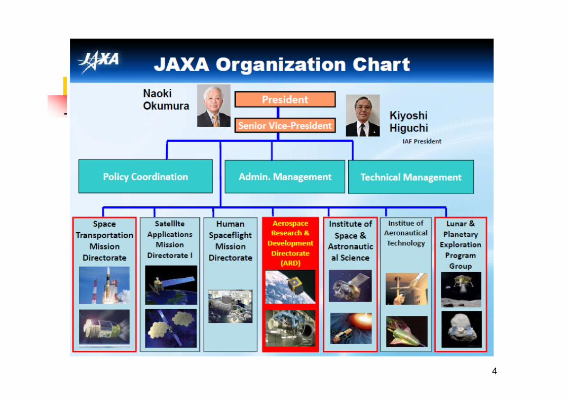
4
5
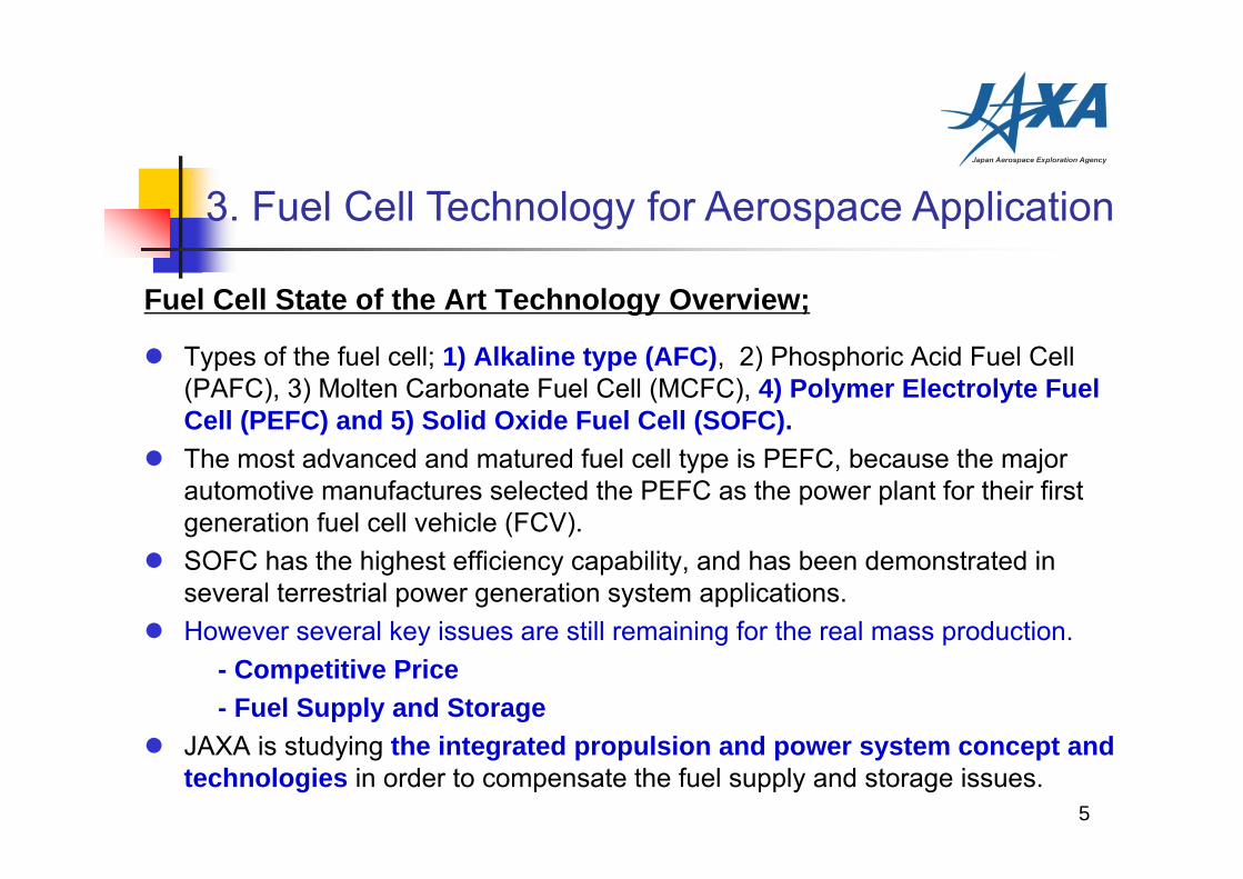
Fuel Cell State of the Art Technology Overview;
Types of the fuel cell; 1) Alkaline type (AFC), 2) Phosphoric Acid Fuel Cell (PAFC), 3) Molten Carbonate Fuel Cell (MCFC), 4) Polymer Electrolyte Fuel Cell (PEFC) and 5) Solid Oxide Fuel Cell (SOFC).
The most advanced and matured fuel cell type is PEFC, because the major automotive manufactures selected the PEFC as the power plant for their first generation fuel cell vehicle (FCV).
SOFC has the highest efficiency capability, and has been demonstrated in several terrestrial power generation system applications.
However several key issues are still remaining for the real mass production.- Competitive Price- Fuel Supply and Storage
JAXA is studying the integrated propulsion and power system concept and technologies in order to compensate the fuel supply and storage issues.
3. Fuel Cell Technology for Aerospace Application
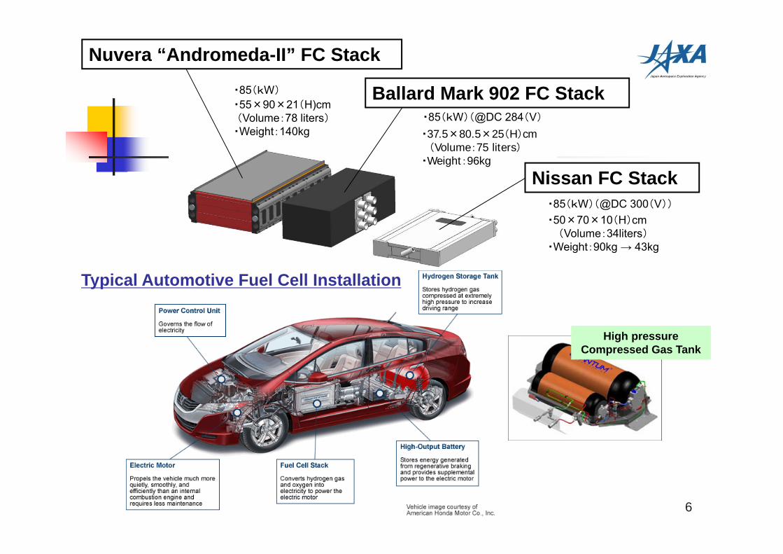
Nuvera “Andromeda-II” FC Stack
Ballard Mark 902 FC Stack
・37.5×80.5×25(H)cm(Volume:75 liters)
・Weight:96kg
・55×90×21(H)cm(Volume:78 liters)・Weight:140kg
・85(kW)(@DC 284(V)
・85(kW)(@DC 300(V))
・50×70×10(H)cm(Volume:34liters)
・Weight:90kg → 43kg
・85(kW)
6
Nissan FC Stack
High pressure Compressed Gas Tank
Typical Automotive Fuel Cell Installation
7
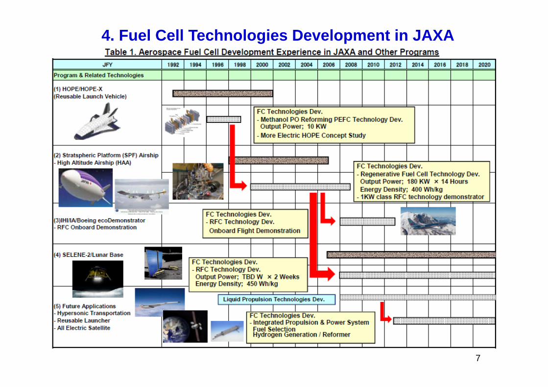
4. Fuel Cell Technologies Development in JAXA
8
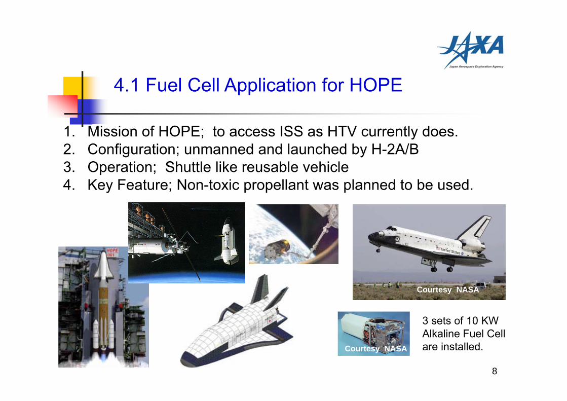
4.1 Fuel Cell Application for HOPE
1. Mission of HOPE; to access ISS as HTV currently does. 2. Configuration; unmanned and launched by H-2A/B3. Operation; Shuttle like reusable vehicle4. Key Feature; Non-toxic propellant was planned to be used.
3 sets of 10 KW Alkaline Fuel Cell are installed.
Courtesy NASA
Courtesy NASA
9
4.1 Fuel Cell Application for HOPE
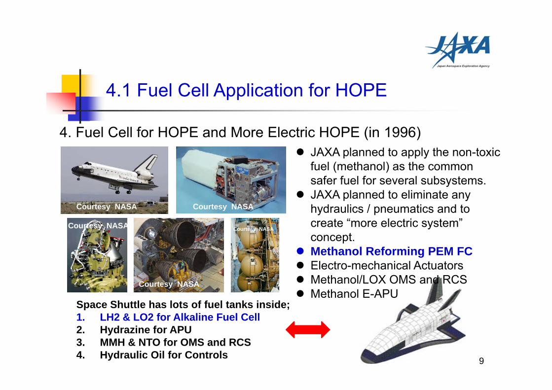
4. Fuel Cell for HOPE and More Electric HOPE (in 1996)
Space Shuttle has lots of fuel tanks inside;1. LH2 & LO2 for Alkaline Fuel Cell2. Hydrazine for APU3. MMH & NTO for OMS and RCS4. Hydraulic Oil for Controls
JAXA planned to apply the non-toxic fuel (methanol) as the common safer fuel for several subsystems.
JAXA planned to eliminate any hydraulics / pneumatics and to create “more electric system” concept.
Methanol Reforming PEM FC Electro-mechanical Actuators Methanol/LOX OMS and RCS Methanol E-APU
Courtesy NASA Courtesy NASA
Courtesy NASA
Courtesy NASA Courtesy NASA
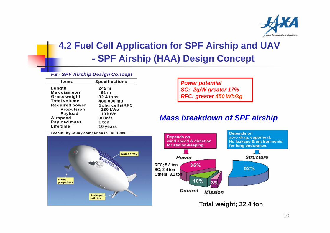
4.2 Fuel Cell Application for SPF Airship and UAV - SPF Airship (HAA) Design Concept
Total weight; 32.4 ton
11 ton
FS - SPF Airship Design ConceptItems Specifications
245 m 61 m32.4 tons480,000 m3Solar cells/RFC 180 kWe 10 kWe30 m/s1 ton10 years
Feasibility Study completed in Fall 1999.
Mass breakdown of SPF airship
Power potential SC: 2g/W greater 17%RFC: greater 450 Wh/kg
RFC; 5.8 tonSC; 2.4 tonOthers; 3.1 ton
10
11
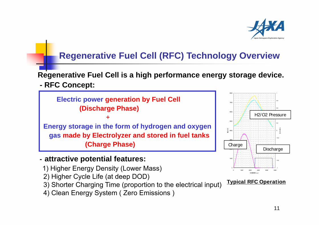
Regenerative Fuel Cell is a high performance energy storage device.- RFC Concept:
Electric power generation by Fuel Cell(Discharge Phase)
+ Energy storage in the form of hydrogen and oxygen
gas made by Electrolyzer and stored in fuel tanks (Charge Phase)
- attractive potential features:1) Higher Energy Density (Lower Mass)2) Higher Cycle Life (at deep DOD)3) Shorter Charging Time (proportion to the electrical input)4) Clean Energy System ( Zero Emissions )
0
1000
2000
3000
4000
5000
6000
7000
8000
0 1000 2000 3000 4000 5000
計測時間(sec)
電力
(W
)
-1
-0.8
-0.6
-0.4
-0.2
0
0.2
0.4
0.6
0.8
1
圧力
(M
Pa)
ChargeDischarge
Typical RFC Operation
Regenerative Fuel Cell (RFC) Technology Overview
H2/O2 Pressure
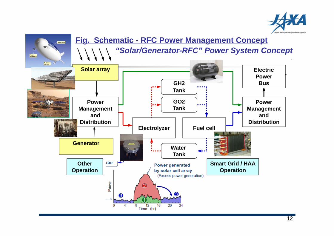
Power Management
and Distribution
GH2Tank
GO2Tank
Power Management
and Distribution
Electric Power Bus
Water Tank
Electrolyzer Fuel cell
“Solar/Generator-RFC” Power System Concept
Solar array
Fig. Schematic - RFC Power Management Concept
Generator
Smart Grid / HAAOperation
Other Operation
12
0
100
200
300
400
500
600
700
800
0 20 40 60 80 100 120 140 160 180
Discharge Time (H) @15KW & 30KW)
Ener
gy D
ens
ity (
Wh/
kg)
15KW Output Power
30KW Output Power
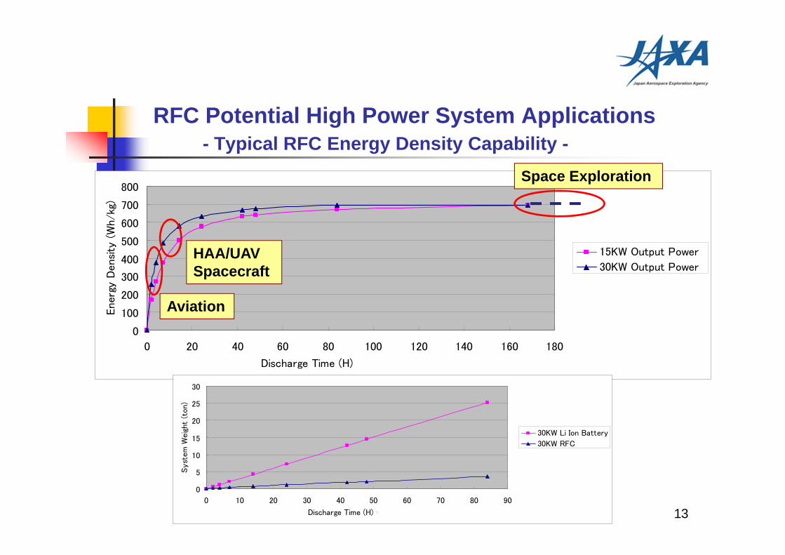
RFC Potential High Power System Applications- Typical RFC Energy Density Capability -
Space Exploration
HAA/UAVSpacecraft
Aviation
0
5
10
15
20
25
30
0 10 20 30 40 50 60 70 80 90
Discharge Time (H) @30KW)
Syst
em
Wei
ght
(ton)
30KW Li Ion Battery
30KW RFC
13
14
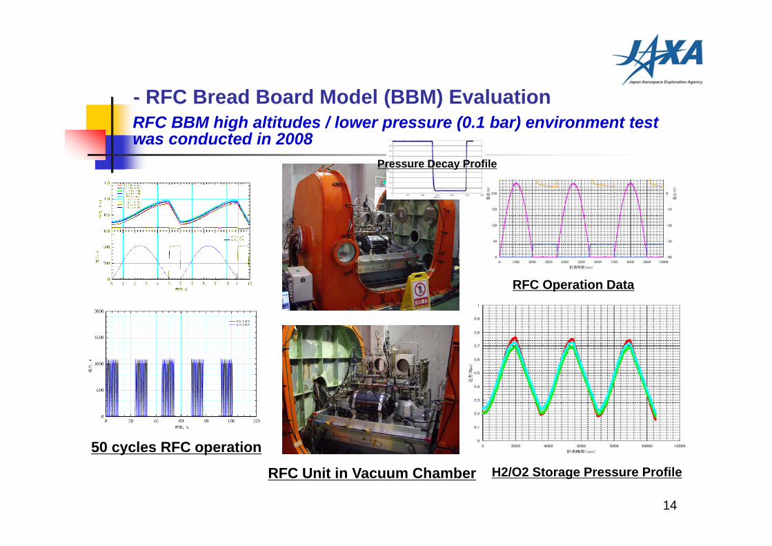
- RFC Bread Board Model (BBM) EvaluationRFC BBM high altitudes / lower pressure (0.1 bar) environment test was conducted in 2008
RFC Unit in Vacuum Chamber
Pressure Decay Profile
RFC Operation Data
H2/O2 Storage Pressure Profile
50 cycles RFC operation
15
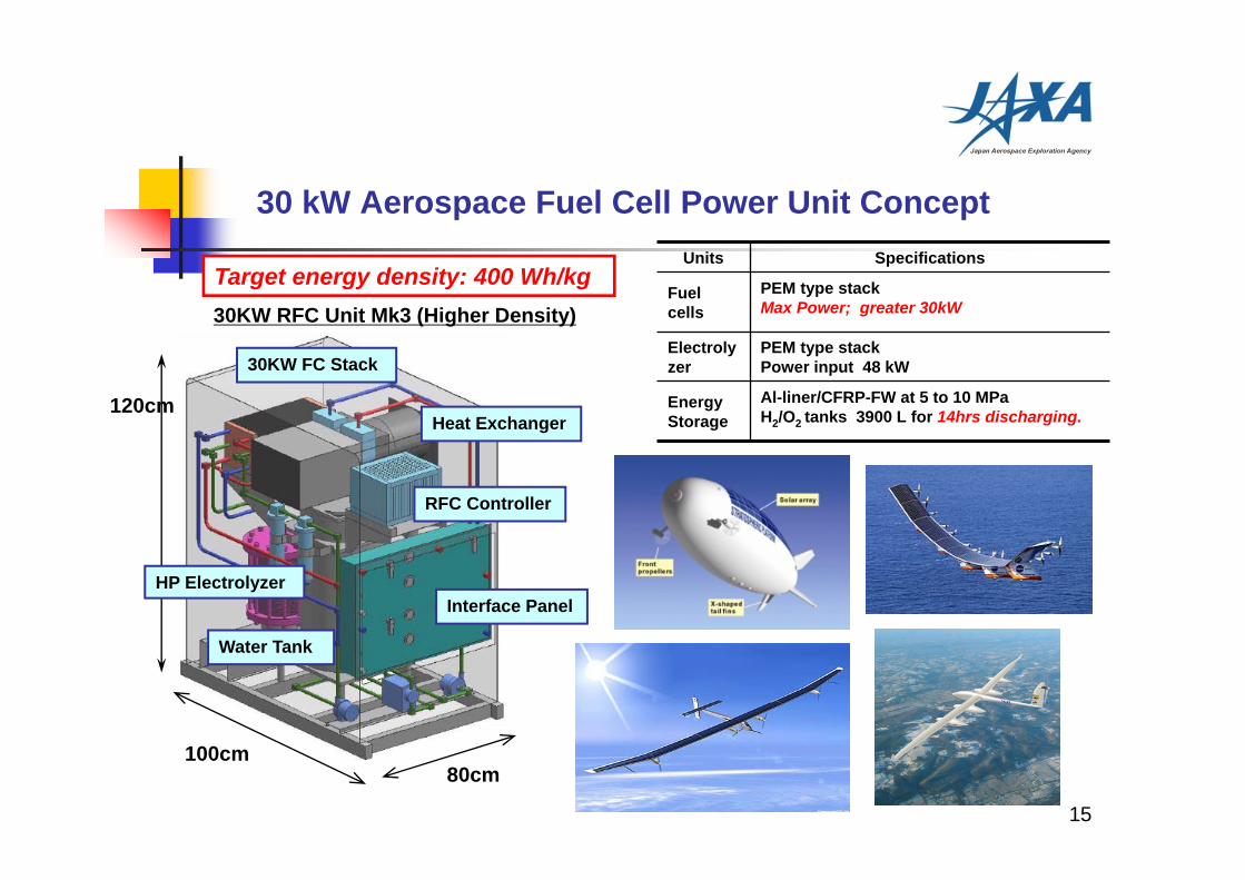
30 kW Aerospace Fuel Cell Power Unit Concept
Target energy density: 400 Wh/kg
30KW FC Stack
Water Tank
RFC Controller
Heat Exchanger
HP Electrolyzer
100cm80cm
120cm
30KW RFC Unit Mk3 (Higher Density)
Interface Panel
Units Specifications
Fuel cells
PEM type stackMax Power; greater 30kW
Electrolyzer
PEM type stackPower input 48 kW
Energy Storage
Al-liner/CFRP-FW at 5 to 10 MPaH2/O2 tanks 3900 L for 14hrs discharging.
16
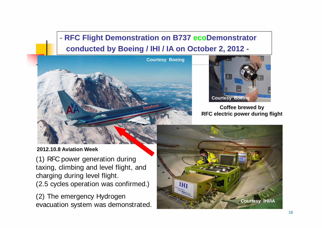
- RFC Flight Demonstration on B737 ecoDemonstrator conducted by Boeing / IHI / IA on October 2, 2012 -
(1) RFC power generation during taxing, climbing and level flight, and charging during level flight. (2.5 cycles operation was confirmed.)
(2) The emergency Hydrogen evacuation system was demonstrated.
Coffee brewed by RFC electric power during flight
2012.10.8 Aviation Week
Courtesy IHI/IA
Courtesy Boeing
Courtesy Boeing
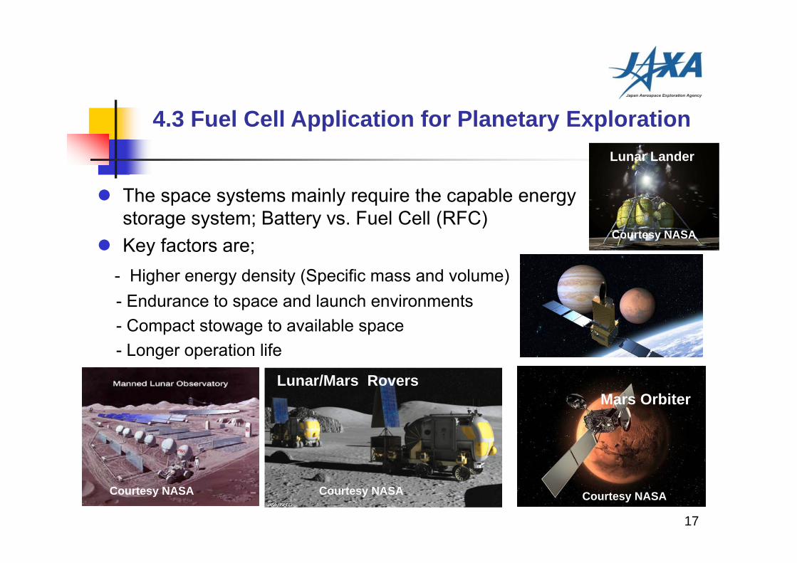
The space systems mainly require the capable energy storage system; Battery vs. Fuel Cell (RFC)
Key factors are;- Higher energy density (Specific mass and volume)- Endurance to space and launch environments- Compact stowage to available space- Longer operation life
17
4.3 Fuel Cell Application for Planetary Exploration
Lunar Lander
Advanced SpacecraftLunar/Mars Rovers
Mars Orbiter
Courtesy NASA
Courtesy NASA
Courtesy NASACourtesy NASA
Lunar Lander
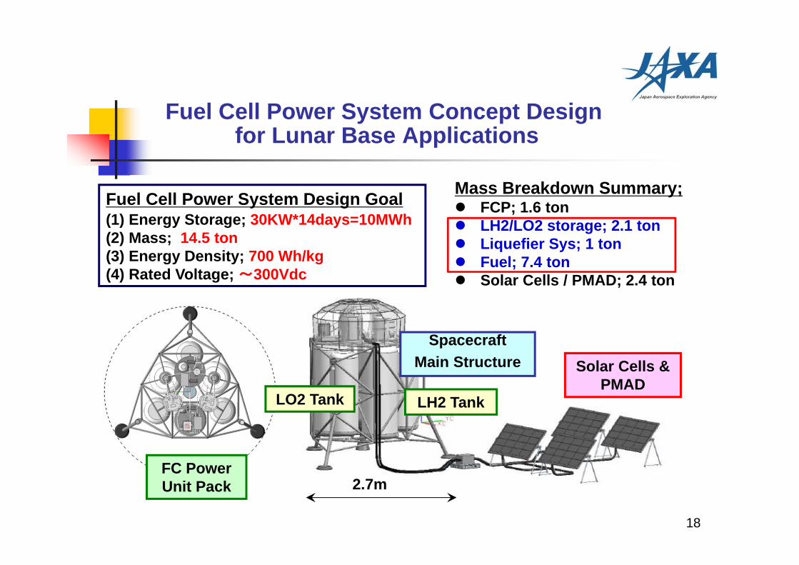
Fuel Cell Power System Concept Designfor Lunar Base Applications
Fuel Cell Power System Design Goal(1) Energy Storage; 30KW*14days=10MWh(2) Mass; 14.5 ton(3) Energy Density; 700 Wh/kg (4) Rated Voltage; ~300Vdc
LO2 Tank LH2 Tank
Solar Cells & PMAD
FC Power Unit Pack
18
Spacecraft Main Structure
2.7m
Mass Breakdown Summary; FCP; 1.6 ton LH2/LO2 storage; 2.1 ton Liquefier Sys; 1 ton Fuel; 7.4 ton Solar Cells / PMAD; 2.4 ton
19
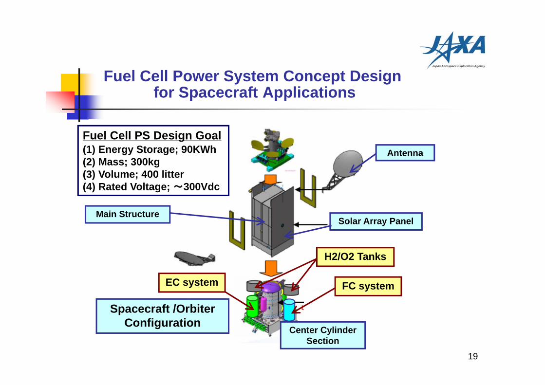
Spacecraft /Orbiter Configuration
H2/O2 Tanks
EC system
Main Structure
Center Cylinder Section
Solar Array Panel
Antenna
Fuel Cell Power System Concept Designfor Spacecraft Applications
FC system
Fuel Cell PS Design Goal(1) Energy Storage; 90KWh(2) Mass; 300kg(3) Volume; 400 litter(4) Rated Voltage; ~300Vdc
20
5. Conclusion
JAXA conducted the fuel cell technologies development for several aerospace applications during past 20 years. However the flight prototypes have not yet existed. One of the reasons is the lack of the funding for the technologies development. Recently the most promising and excellent fuel cell state of the art technologies are demonstrated in the automotive or terrestrial programs. The collaboration with these commercial programs will bring lots of benefit to the aerospace high electric power systems advancement.
As the conclusion, I would like to promote the aerospace fuel cell power plant technologies early realization for the future high power system applications collaborating with the advanced commercial programs.


![01 Japan Sentinel Asia.ppt [Read-Only] · Mudslide at Mt. Mayon, Philippines. Japan Aerospace Exploration Agency 30 Satellite Images before and after Disaster. Japan Aerospace Exploration](https://img.pdfslide.us/doc/110x75/60009a70adb04f73302aa29e/01-japan-sentinel-asiappt-read-only-mudslide-at-mt-mayon-philippines-japan.jpg)