Embed Size (px)
Citation preview
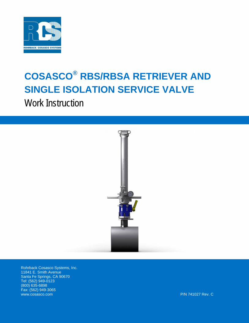
COSASCO® RBS/RBSA RETRIEVER AND SINGLE ISOLATION SERVICE VALVE Work Instruction
Rohrback Cosasco Systems, Inc. 11841 E. Smith Avenue Santa Fe Springs, CA 90670 Tel: (562) 949-0123 (800) 635-6898 Fax: (562) 949-3065 www.cosasco.com P/N 741027 Rev. C
COSASCO® RBS/RBSA Retriever and Single Isolation Service Valve Work Instruction
P/N: 741027 Rev. C
Scheduled Review Date: January 1, 2014
Page: 2 of 42Date: 02/27/2013
COSASCO® is a registered trademark of Rohrback Cosasco Systems, Inc. No part of this work instruction may be reproduced or transmitted in any form or by any means, electronic or mechanical, including photocopying and recording, for any purpose, without the express written permission of Rohrback Cosasco Systems, Inc.
COSASCO® RBS/RBSA Retriever and Single Isolation Service Valve Work Instruction
P/N: 741027 Rev. C
Scheduled Review Date: January 1, 2014
Page: 3 of 42Date: 02/27/2013
CONTENTS
Page No
1 Important Instructions ........................................................................................ 5
2 Notice .................................................................................................................... 6
3 Safety Warnings ................................................................................................... 7
4 Scope of Document ............................................................................................. 8
5 How the Cosasco System Works ....................................................................... 8
5.1 Access Fittings .......................................................................................................... 8 5.2 The Retrieval Tool .................................................................................................. 10 5.3 The Service Valve (Single Isolation) ....................................................................... 11 5.4 Back Pressure Pump .............................................................................................. 12
6 Pre Job Preparation .......................................................................................... 13
6.1 Site Survey .............................................................................................................. 13 6.2 Documentation & Communication ........................................................................... 13 6.3 On-site equipment and Worksite Checks ................................................................ 14
7 Retrieval and Installation of Devices from 2” System Access Fittings ....... 14
7.1 Removal of Caps from Access Fittings ................................................................... 14 7.2 Access Fitting Preparation & Installation of Service Valve ...................................... 15 7.3 Installation of Retrieval Tool .................................................................................... 16 7.4 Back Pressuring Procedure – Device Retrieval ...................................................... 17 7.5 Removal of Carrier Plug .......................................................................................... 20 7.6 Preparation of the Carrier Plug & Device ................................................................ 21 7.7 Installation of the Retrieval Tool .............................................................................. 22 7.8 Back Pressure Retriever – Device Installation ........................................................ 23 7.9 Installation of the Carrier Plug ................................................................................. 26 7.10 Carrier Plug Orientation & Access Fitting Cap Installation ...................................... 28
8 Special Tools & Procedures ............................................................................ 30
8.1 Pressure Testing Procedure ................................................................................... 30 8.2 Thread Tap Assembly (P/N 125111) ....................................................................... 32 8.3 Overshot Adapter (P/N 126292) .............................................................................. 34 8.4 Surge Tube Assembly (P/N 123672) ...................................................................... 35 8.5 Thread Brush Assembly (P/N 125116) ................................................................... 37 8.6 Seat Reamer (P/N 125125) ..................................................................................... 38 8.7 Steel Pipe Plug Adapter (P/N 125115) .................................................................... 39
COSASCO® RBS/RBSA Retriever and Single Isolation Service Valve Work Instruction
P/N: 741027 Rev. C
Scheduled Review Date: January 1, 2014
Page: 4 of 42Date: 02/27/2013
COSASCO® RBS/RBSA Retriever and Single Isolation Service Valve Work Instruction
P/N: 741027 Rev. C
Scheduled Review Date: January 1, 2014
Page: 5 of 42Date: 02/27/2013
1 IMPORTANT INSTRUCTIONS
Rohrback Cosasco Systems is committed to providing the safest and highest quality products, services, and training for the industries it serves. We are committed to ensuring that all users of our equipment work safely and efficiently. Fully anticipating the infinite variety of conditions that may be encountered in the field would be impossible, but we have designed this work instruction to emphasize safe working practices, and as much as possible, to convey the full benefit of our knowledge and collective experience in the use of the COSASCO RBS/RBSA Retriever and single isolation Service Valve. This work instruction is not meant to be a sole source of instruction or training guide. Because these tools are used in a broad range of environments and applications, it is important that the owner and operation personnel have been assessed, certified, and deemed competent in all safety, work management and additional risk assessment requirements in the application of this procedure.
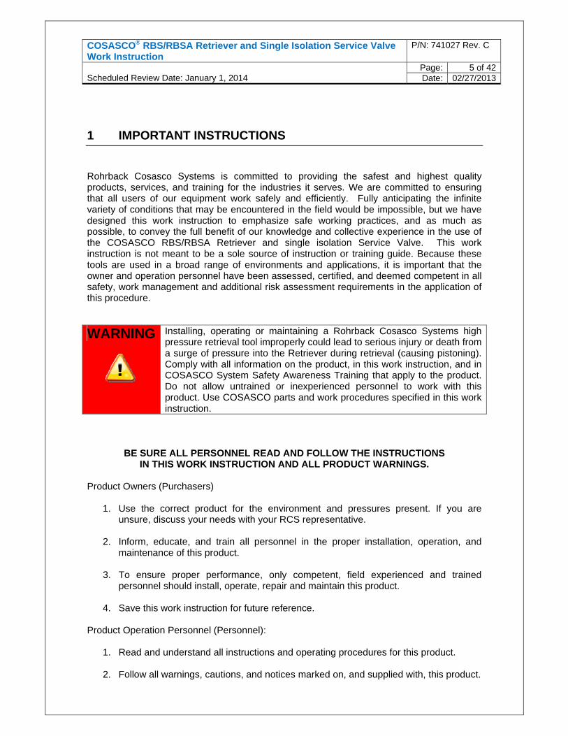
WARNING Installing, operating or maintaining a Rohrback Cosasco Systems high pressure retrieval tool improperly could lead to serious injury or death from a surge of pressure into the Retriever during retrieval (causing pistoning). Comply with all information on the product, in this work instruction, and in COSASCO System Safety Awareness Training that apply to the product. Do not allow untrained or inexperienced personnel to work with this product. Use COSASCO parts and work procedures specified in this work instruction.
BE SURE ALL PERSONNEL READ AND FOLLOW THE INSTRUCTIONS IN THIS WORK INSTRUCTION AND ALL PRODUCT WARNINGS.
Product Owners (Purchasers)
1. Use the correct product for the environment and pressures present. If you are unsure, discuss your needs with your RCS representative.
2. Inform, educate, and train all personnel in the proper installation, operation, and maintenance of this product.
3. To ensure proper performance, only competent, field experienced and trained personnel should install, operate, repair and maintain this product.
4. Save this work instruction for future reference. Product Operation Personnel (Personnel):
1. Read and understand all instructions and operating procedures for this product.
2. Follow all warnings, cautions, and notices marked on, and supplied with, this product.
COSASCO® RBS/RBSA Retriever and Single Isolation Service Valve Work Instruction
P/N: 741027 Rev. C
Scheduled Review Date: January 1, 2014
Page: 6 of 42Date: 02/27/2013
3. Follow all instructions during the installation, operation, and maintenance of this
product.
4. To prevent personal injury, ensure that all components are in place prior to and during operation of the product.
5. If you do not understand an instruction, or do not feel comfortable following the instructions, contact an RCS service technician for clarification or assistance.
6. If this work instruction is not correct for your RCS product, contact your regional RCS office and RCS will provide you with the requested work instruction.
7. Use only replacement parts specified by RCS. Unauthorized parts and procedures can affect this product’s performance, safety, and invalidate the warranty. “Look-a-like” substitutions may result in improper operation and may result in serious injury or death.
8. Save this work instruction for future reference.
2 NOTICE
Information provided in this work instruction should not be considered as all encompassing or suitable for all situations, conditions or environments. Each individual and the organization he/she represents is responsible for implementing the training provided and its/his/her own safety/injury/illness prevention program in connection with this work instruction, and should consult with their respective legal, medical or other advisors as to the suitability of using the information in connection with this work instruction.
Application of information furnished by this work instruction does not guarantee that the information furnished will meet applicable USA (including OSHA), United Kingdom, or any other country’s health or safety standards or requirements or, by implementing any of the programs, that you or your company will be compliant with such rules and regulations.
Rohrback Cosasco Systems, Inc., and its affiliates assume no liability arising from the use of, or reliance on the information provided in any of the RCS work instructions. Always seek the advice of your legal, medical or other advisors before using this information.
NEITHER ROHRBACK COSASCO® SYSTEMS, INC., NOR ITS INSTRUCTORS ARE RESPONSIBLE FOR THE USE BY ANY ORGANIZATION OF THIS WORK INSTRUCTION OR ANY INFORMATION CONTAINED HEREIN. ANY PERSON OR ORGANIZATION UTILIZING THIS WORK INSTRUCTION, FOR ANY PURPOSE, DOES SO AT ITS/HIS/HER OWN RISK.
COSASCO® RBS/RBSA Retriever and Single Isolation Service Valve Work Instruction
P/N: 741027 Rev. C
Scheduled Review Date: January 1, 2014
Page: 7 of 42Date: 02/27/2013
3 SAFETY WARNINGS
1. Safe operation requires two experienced and competent operators.
2. Do not use this retrieval equipment unless you have been trained and are competent
in its safe operation.
3. If it has been longer than 90 days since your last operation, you should review the work instruction and complete an operation on a pressurized test rig.
4. Make sure you have complied with all plant safety requirements and environmental
regulations.
5. Identify the type of media its pressure and temperature. Review material safety data information on the media prior to operation.
6. Ensure you have all the required safety equipment for the given media, "i.e. hard hat,
safety glasses, protective clothing, safety gloves, respirator, spill safety equipment, etc...
7. Any actions which could vary system pressure such as surges caused by opening
and closing of valves and chokes must be delayed until completion of retrieval operations.
8. Ensure you have enough clearance for safe operation. Note wind direction prior to
starting operations involving hazardous products.
9. Warning: Surface temperature may be hot. Contact may cause burn.
10. Warning: Do not exceed equipment specified pressure rating. Over-pressurization can cause equipment to fail/burst posing a variety of safety hazards.
11. Warning: Be sure to introduce pressure gradually into the tooling by opening the appropriate valve slowly. This safety measure is taken to prevent pistoning. UNCONTROLLED PISTONING MAY CAUSE SERIOUS INJURY OR DEATH!
12. Warning: Do not apply a load of more than 150 pounds, perpendicular to the Retriever body axis, to prevent breakage from bending stresses.
WARNING
It is imperative that the following safety warnings are taken into important consideration before and during use of Retrieval Equipment. Safety warnings are noted throughout this document to ensure precautions are taken for all procedures where there are risks involved. Failure to follow these warnings could result in serious injury or death.
COSASCO® RBS/RBSA Retriever and Single Isolation Service Valve Work Instruction
P/N: 741027 Rev. C
Scheduled Review Date: January 1, 2014
Page: 8 of 42Date: 02/27/2013
4 SCOPE OF DOCUMENT
This document details the procedure for the installation and retrieval of corrosion and erosion monitoring devices or chemical injection equipment using the Rohrback Cosasco Systems RBS/RBSA Retrieval Tool and Single Isolation Service Valve from 2” system access fittings. Also included is the use of special ancillary tools in conjunction with the Retriever and Service Valve. These tools are designed to allow installation and retrieval of the above mentioned devices from access fittings without shutdown when production pipework is at full operating pressure. This document is not to be used as a training manual in the use of the fore mentioned equipment and is intended for use by Rohrback Cosasco Systems (RCS) trained and qualified personnel or service personnel of clients who have been assessed, certified, and deemed competent in all safety, work management and additional risk assessment requirements in the application of this procedure.
5 HOW THE COSASCO SYSTEM WORKS
5.1 Access Fittings
COSASCO® RBS/RBSA Retriever and Single Isolation Service Valve Work Instruction
P/N: 741027 Rev. C
Scheduled Review Date: January 1, 2014
Page: 9 of 42Date: 02/27/2013
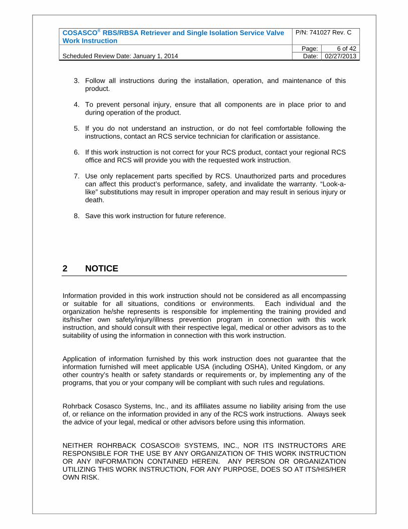
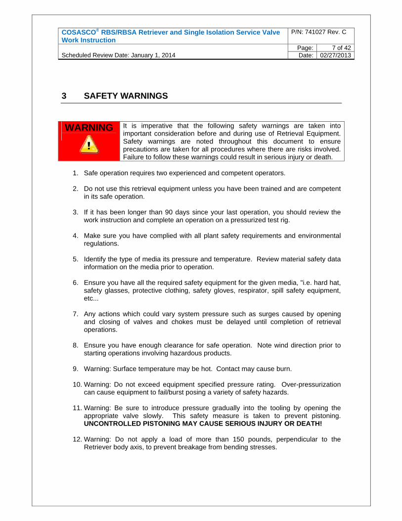
The COSASCO Access Fitting Assembly is the key to the concept of “Access under pressure - any time, any place”. When used with a COSASCO Retriever and Service Valve, the Access Fitting Assembly permits safe, easy insertion and retrieval of corrosion and erosion monitoring systems as well as preventive maintenance devices for injecting inhibitors or for sampling, etc. while under full operating pressure. The COSASCO Access Fitting Body is available in several standard mounting configurations, including Flarweld, Buttweld, Socketweld, NPT, and Flanged. Access Fitting bodies are available in a wide variety of materials. Typically, the Access Fitting body material will be chosen to be compatible with the pipe or vessel material. The Access Fitting consists of the body, a hollow or solid plug assembly, and a pressure retaining or protective cover.
Pressure Retaining Cover/Thread Protector
Hollow Plug Assembly
Solid Plug Assembly
Coupon Holder
Metal Loss Coupons
Electronic Probe
Flarweld Buttweldolet Socketweld NPT Flanged
Access Fitting
COSASCO® RBS/RBSA Retriever and Single Isolation Service Valve Work Instruction
P/N: 741027 Rev. C
Scheduled Review Date: January 1, 2014
Page: 10 of 42Date: 02/27/2013
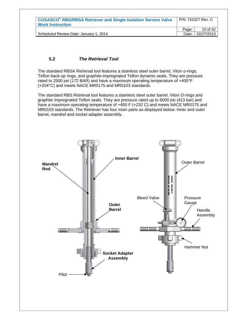
5.2 The Retrieval Tool
The standard RBSA Retrieval tool features a stainless steel outer barrel, Viton o-rings, Teflon back-up rings, and graphite-impregnated Teflon dynamic seals. They are pressure rated to 2500 psi (172 BAR) and have a maximum operating temperature of +400°F (+204°C) and meets NACE MR0175 and MR0103 standards. The standard RBS Retrieval tool features a stainless steel outer barrel, Viton O-rings and graphite impregnated Teflon seals. They are pressure rated up to 6000 psi (413 bar) and have a maximum operating temperature of +450 F (+232 C) and meets NACE MR0175 and MR0103 standards. The Retriever has four main parts as displayed below: Inner and outer barrel, mandrel and socket adapter assembly.
Inner BarrelMandrel Rod
Outer Barrel
Socket Adapter Assembly
Pressure Gauge
Bleed Valve
Hammer Nut
Handle Assembly
Pilot
Outer Barrell
COSASCO® RBS/RBSA Retriever and Single Isolation Service Valve Work Instruction
P/N: 741027 Rev. C
Scheduled Review Date: January 1, 2014
Page: 11 of 42Date: 02/27/2013
The most commonly used retrieval tools come in 18”, 25” & 37” stroke lengths. The stroke length determines the length of device the retrieval tool can accommodate for installation or retrieval. Some useful retrieval tool specifications are included in the table below. RBS/RBSA Retriever Stroke Length
Clearance required for removal of retrieval tool (measured from top of
the access fitting)
Weight Maximum Device Length (S) Solid Plug or (H) Hollow Plug using 3600 psi Service Valve RBS RBSA
18” 52.25” (132.7cm) 56lb(25.4kg) 45lb(20.4kg)9.00” (22.8cm) (S)
8.00” (20.3cm) (H)
25” 66.25” (168.2cm) 64lb(29.0kg) 53lb(24.0kg)16.00” (40.6cm) (S)
15.00” (38.1cm) (H)
37” 90.25” (229.2cm) 81lb(36.7kg) 70lb(31.8kg)28.00” (71.1cm) (S)
27.00” (68.5cm) (H)
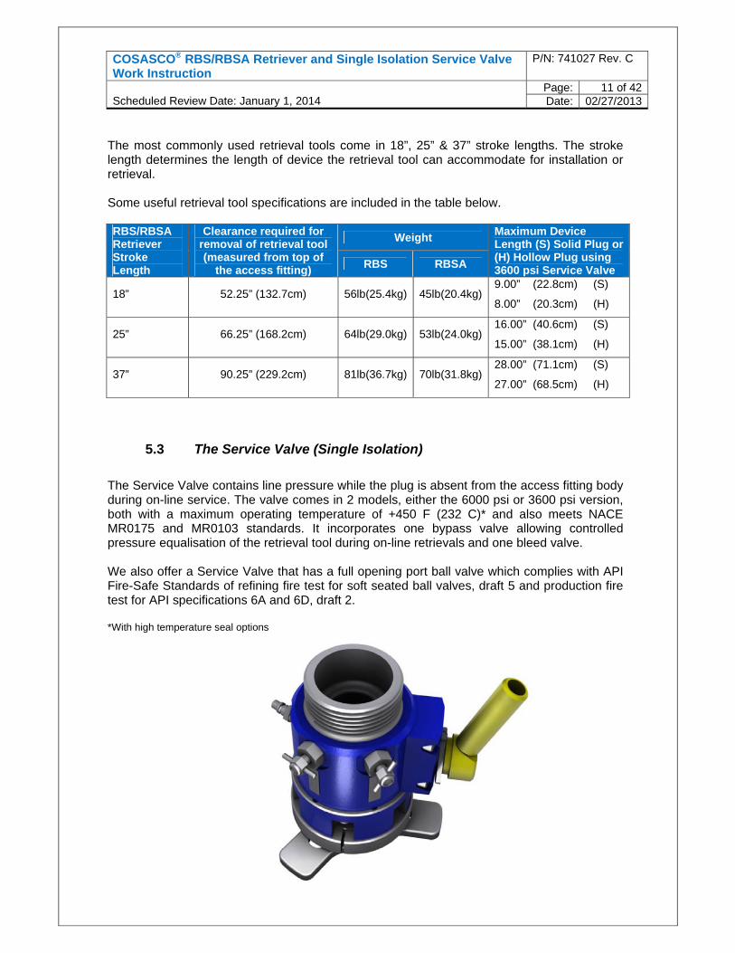
5.3 The Service Valve (Single Isolation)
The Service Valve contains line pressure while the plug is absent from the access fitting body during on-line service. The valve comes in 2 models, either the 6000 psi or 3600 psi version, both with a maximum operating temperature of +450 F (232 C)* and also meets NACE MR0175 and MR0103 standards. It incorporates one bypass valve allowing controlled pressure equalisation of the retrieval tool during on-line retrievals and one bleed valve. We also offer a Service Valve that has a full opening port ball valve which complies with API Fire-Safe Standards of refining fire test for soft seated ball valves, draft 5 and production fire test for API specifications 6A and 6D, draft 2. *With high temperature seal options
COSASCO® RBS/RBSA Retriever and Single Isolation Service Valve Work Instruction
P/N: 741027 Rev. C
Scheduled Review Date: January 1, 2014
Page: 12 of 42Date: 02/27/2013
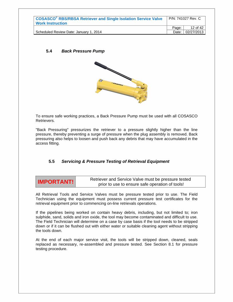
5.4 Back Pressure Pump
To ensure safe working practices, a Back Pressure Pump must be used with all COSASCO Retrievers. "Back Pressuring" pressurizes the retriever to a pressure slightly higher than the line pressure, thereby preventing a surge of pressure when the plug assembly is removed. Back pressuring also helps to loosen and push back any debris that may have accumulated in the access fitting.
5.5 Servicing & Pressure Testing of Retrieval Equipment
All Retrieval Tools and Service Valves must be pressure tested prior to use. The Field Technician using the equipment must possess current pressure test certificates for the retrieval equipment prior to commencing on-line retrievals operations. If the pipelines being worked on contain heavy debris, including, but not limited to; iron sulphide, sand, solids and iron oxide, the tool may become contaminated and difficult to use. The Field Technician will determine on a case by case basis if the tool needs to be stripped down or if it can be flushed out with either water or suitable cleaning agent without stripping the tools down. At the end of each major service visit, the tools will be stripped down, cleaned, seals replaced as necessary, re-assembled and pressure tested. See Section 8.1 for pressure testing procedure.
IMPORTANT! Retriever and Service Valve must be pressure tested prior to use to ensure safe operation of tools!
COSASCO® RBS/RBSA Retriever and Single Isolation Service Valve Work Instruction
P/N: 741027 Rev. C
Scheduled Review Date: January 1, 2014
Page: 13 of 42Date: 02/27/2013
6 PRE JOB PREPARATION
The following three sections discuss the major steps required, prior to starting any on-line retrieval using the RBS/RBSA retrieval tool and Service Valve. The lists in the following sections are prompts and are not intended to replace client Risk Assessments or Job Safety Analysis, which will also have to be completed prior to work start.
6.1 Site Survey
It is necessary to perform a survey of each work location prior to work start, to ensure the following variable information is known:
Scaffolding or any additional access requirements to ensure safe access and egress to work site
Clearance for using the Retrieval Tool and Service Valve. See table in section 5.2 for guidance on extension clearances required. A 1.5 M radial clearance around the retrieval tool will also be required for its operation
Pipe line pressures & temperatures, so that operating pressure of tools is not exceeded
Any potential hazards around the worksites, such as slip, trip or fall hazards Emergency access & egress routes The pipe line media, which the equipment and operators will be exposed to Means of raising alarm in emergency situations
6.2 Documentation & Communication
Prior to work start the following documentation must be generated and reviewed:
Permit to Work, as specified by the client Client specific Risk Assessment or Job Step Analyses, with RCS personnel input Pressure test certificates for Retrieval tool & Service valve Personnel competency certificates
A toolbox talk will be performed by the lead Engineer (RCS or Client), including but not limited to the following:
The main steps involved in the job Equipment to be used Review of work permit and risk assessment PPE required Means of communication with Control Room personnel Actions to be taken in the event of an emergency Control room is aware of work party location All personnel involved with the work are aware of all control measures and are
competent to be involved in the work
COSASCO® RBS/RBSA Retriever and Single Isolation Service Valve Work Instruction
P/N: 741027 Rev. C
Scheduled Review Date: January 1, 2014
Page: 14 of 42Date: 02/27/2013
Work party are aware of any other work taking place in close proximity to worksite Any additional hazards identified during this talk should be reviewed and control
measures implemented
6.3 On-site equipment and Worksite Checks
Upon completion of the steps in section 6.1 & 6.2 final checks should be made at the worksite prior to work start, including equipment checks and worksite checks as follows: Worksite
Ensure any scaffolding to be worked on is certified and is of safe design Check previously identified escape routes are still clear Test means of communication with control room Double check PPE is in good condition and fit for purpose Identify any other work parties in proximity to the work location
Retrieval Equipment
Inspect the Service Valve O-ring, which seats on the access fitting for any damage Inspect the Retriever O-ring which mates with the service valve at the hammer union Extend and collapse the Retriever inner barrel to ensure it is free to move and does
not display any sign of binding Open and close the Service Valve to ensure that the ball valve is free to move and
does not display any sign of binding Ensure that the Socket adapter assembly on the Retriever is adjusted to suit the
valve in use (ie holes 2&4 for single valve) and device being installed or removed to / from the access fitting.
7 RETRIEVAL AND INSTALLATION OF DEVICES FROM 2” SYSTEM ACCESS FITTINGS
WARNING!
It is imperative for the operator to first determine pressure, temperature, and the type of media before the retrieval operation is started. Any action which could vary pressure, such as surges caused by the opening or closing of valves or chokes, must be delayed until after the retrieving operation has been completed. Failure to determine line pressure or change in line pressure will not let the operator determine if the Retriever has been completely pressurized potentially leading to pistoning of the Retriever, resulting in serious injury or death!
7.1 Removal of Caps from Access Fittings
1. If a thread protecting cap is installed, use a C’ spanner to remove the cap.
2. If a pressure bearing cap is fitted, check gauge for pressure indication, if none is
indicated open the bleed valve on cap to confirm no pressure is present and proceed to step 4. If pressure is present proceed to step 3 below.
COSASCO® RBS/RBSA Retriever and Single Isolation Service Valve Work Instruction
P/N: 741027 Rev. C
Scheduled Review Date: January 1, 2014
Page: 15 of 42Date: 02/27/2013
3. If pressure is indicated on the pressure gauge of the cap, attempt to bleed off the
pressure to assess the rate of leak past the carrier plug primary seal or the probe seal. If it is possible to bleed off pressure within 10 seconds, close the valve and check for speed of build-up. If pressure builds up within 2 minutes the cap cannot be removed and a shutdown will be required to remove the cap. If pressure does not build up, proceed to step 4 below.
4. Once the cap has been confirmed free of pressure, unscrew the cap using a C spanner.
If a Swagelok probe adapter is installed through the cap, the adapter will have to be removed prior to removal or turning of the cap. Once the Swagelok nut is completely unthreaded pull the probe extension adapter away from the cap, this disconnects the adapter from the probe pins. Keeping a slight pulling pressure on the adapter unscrew the pressure retaining cover from the access fitting using a C spanner if necessary. It may be necessary for 2 operators to carry out this operation.
7.2 Access Fitting Preparation & Installation of Service Valve
1. Remove either the 1/2” SS pipe plug or 1/2” red plastic pipe plug from the hex of the
carrier plug. If at any stage during removal of SS pipe plug (if fitted), line product can be seen travelling up the plug threads STOP and re-tighten hand tight. An overshot adapter in conjunction with back pressure pump will have to be used for removal of the carrier plug – see special tools and adapters in section 8 of this procedure.
2. If no indication of pressure is present remove the pipe plug and clean any grease or deposits from the external threads and sealing face of the access fitting. If excess corrosion product is present on any of the surfaces, attempt to remove using a wire brush. The external sealing face of the access fitting must be smooth and free of pitting, to ensure a good seal is made between the valve and access fitting.
3. When the access fitting has been cleaned, apply non metallic grease to the threads and sealing face of the access fitting.
4. Loosen the carrier plug using a 1- 1/8” ring spanner ¼ turn maximum.
IMPORTANT! DO NOT loosen beyond the 1/4 turn maximum or leakage will result!
5. Check the Service Valve as follows:
Service Valve is open Bleed valve is closed By-pass valve is closed O-Ring is in good condition
WARNING!
If there is pressure build-up after a waiting period of 2 minutes as noted in the previous step, do not remove cap! A leak has occurred between the access fitting and plug assembly seal. A shutdown will be required to remove the cap. Serious injuries may occur if the cap is removed with pressure build-up.
COSASCO® RBS/RBSA Retriever and Single Isolation Service Valve Work Instruction
P/N: 741027 Rev. C
Scheduled Review Date: January 1, 2014
Page: 16 of 42Date: 02/27/2013
6. Install Service Valve on to the access fitting ensuring that the valve handle is positioned
so that the valve can be opened and closed, and then tighten the hammer union with a non sparking hammer; ensuring valve is in the open position and firmly seated on the access fitting.
7.3 Installation of Retrieval Tool
1. With two RCS trained operators, mate Retriever to Service Valve. Pull the inner barrel up approximately 5 inches and lift the retrieval tool in to position to mate it with the valve, then rotate the Retriever hammer union clockwise and tighten using a non-sparking hammer. Note - Prior to lifting the Retriever, if the access fitting is in a top of line position, it may be necessary to use a barrel clamp on the Retriever inner barrel to maintain its position once Retriever is inverted.
2. Double check that the Retriever bleed valve is closed & Service Valve bleed and bypass
valves are closed.
Read the following warnings and make sure that you carefully review every step of the
procedure.
Never stand under or over the Retriever! Line Pressure must be identified! Do not proceed until you have verified line
pressure! If line pressure cannot be verified, do not proceed! Make sure there is adequate clearance area. Ensure both operators performing the retrieval are always clear of the Retriever
barrel and handle in case pistoning occurs. Always keep body and head as far away from the Retriever as possible when
performing pressurization. For all applications, retrievals must always be "back pressured" using back pressure
pump or other method of back pressuring, due to build-up of solids in the access fitting that may cause blockage.
Check pressure gauge on Retriever to verify that it is working properly.
IMPORTANT! WEAR SAFETY GLASSES! USE NON-SPARKING HAMMER!
WARNING!
Double check that both the Retriever bleed valve and Service Valve bleed valve and bypass valve are closed! Leakage will result when plug assembly is disengaged. Leakage of volatile or high temperature media could result in serious injuries!
WARNING!
The next step includes "pressuring balancing" of the Retriever. Pressure balance between the line and the Retriever is crucial. If the Retriever is not pressure balanced when plug is removed, a surge of pressure will cause the Retriever to piston possibly resulting in serious injuries or death!
COSASCO® RBS/RBSA Retriever and Single Isolation Service Valve Work Instruction
P/N: 741027 Rev. C
Scheduled Review Date: January 1, 2014
Page: 17 of 42Date: 02/27/2013
7.4 Back Pressuring Procedure – Device Retrieval
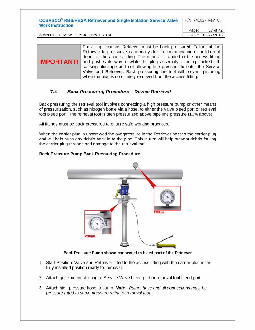
Back pressuring the retrieval tool involves connecting a high pressure pump or other means of pressurization, such as nitrogen bottle via a hose, to either the valve bleed port or retrieval tool bleed port. The retrieval tool is then pressurized above pipe line pressure (10% above). All fittings must be back pressured to ensure safe working practices. When the carrier plug is unscrewed the overpressure in the Retriever passes the carrier plug and will help push any debris back in to the pipe. This in turn will help prevent debris fouling the carrier plug threads and damage to the retrieval tool. Back Pressure Pump Back Pressuring Procedure:
Back Pressure Pump shown connected to bleed port of the Retriever
1. Start Position: Valve and Retriever fitted to the access fitting with the carrier plug in the fully installed position ready for removal.
2. Attach quick connect fitting to Service Valve bleed port or retrieval tool bleed port.
3. Attach high pressure hose to pump. Note - Pump, hose and all connections must be pressure rated to same pressure rating of retrieval tool.
IMPORTANT!
For all applications Retriever must be back pressured. Failure of the Retriever to pressurize is normally due to contamination or build-up of debris in the access fitting. The debris is trapped in the access fitting and pushes its way in while the plug assembly is being backed off, causing blockage and not allowing line pressure to enter the Service Valve and Retriever. Back pressuring the tool will prevent pistoning when the plug is completely removed from the access fitting.
COSASCO® RBS/RBSA Retriever and Single Isolation Service Valve Work Instruction
P/N: 741027 Rev. C
Scheduled Review Date: January 1, 2014
Page: 18 of 42Date: 02/27/2013
4. Connect other end of hose to retrieval tool or Service Valve (depending on orientation) via the quick connect coupling.
5. Fill pump reservoir with desired fluid, potable water will normally be used although hydraulic oil can be used if required.
6. Open the bleed valve on the Retriever and Service Valve bleed ports.
7. Begin actuating the pump. Once the Retriever and Service Valve are full (purged), close the bleed valve that does not have hose attached.
Keep pumping until pressure indicated on pump or retrieval tool pressure gauge is 10% psi above line operating pressure.
8. Once the desired pressure has been achieved, close the bleed valve on the retrieval tool
or Service Valve.
9. Release the pressure back to pump reservoir from the hose via the pump valve. 10. Disconnect the hose from the retrieval tool or Service Valve.
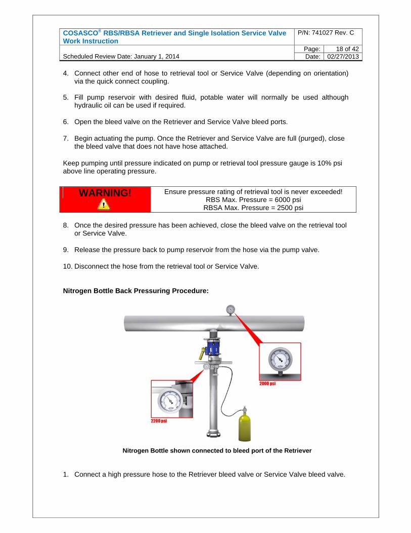
Nitrogen Bottle Back Pressuring Procedure:
Nitrogen Bottle shown connected to bleed port of the Retriever
1. Connect a high pressure hose to the Retriever bleed valve or Service Valve bleed valve.
WARNING! Ensure pressure rating of retrieval tool is never exceeded! RBS Max. Pressure = 6000 psi
RBSA Max. Pressure = 2500 psi
COSASCO® RBS/RBSA Retriever and Single Isolation Service Valve Work Instruction
P/N: 741027 Rev. C
Scheduled Review Date: January 1, 2014
Page: 19 of 42Date: 02/27/2013
2. Nitrogen bottle connection. Connect the other end of the high pressure hose to the nitrogen bottle outlet. It is recommended that:
The nitrogen bottle pressure be at least 200 psi (13 BAR) higher than the line
pressure. The nitrogen bottle be equipped with a regulator. The nitrogen bottle be fitted with a bleed valve. (This is desirable to allow bleeding
down the hose after back pressuring is completed). 3. Nitrogen bottle control valve. Open the control valve and allow pressure build-up within
the hose to 200 (14 bar) to 300 psi (21 bar) above the line pressure.
4. Open the Retriever bleed valve or Service Valve bleed valve. 5. Allow the nitrogen pressure to enter the Retriever. 6. Once the desired pressure has been achieved, close the bleed valve on the retrieval tool
or Service Valve.
7. Close the nitrogen bottle control valve. Bleed off the pressure within the hose and
disconnect it from the Retriever bleed valve.
8. Connect a high pressure hose to the Retriever bleed valve or Service Valve bleed valve. 9. Nitrogen bottle connection. Connect the other end of the high pressure hose to the
nitrogen bottle outlet. It is recommended that:
The nitrogen bottle pressure be at least 200 psi (13 BAR) higher than the line pressure.
The nitrogen bottle be equipped with a regulator. The nitrogen bottle be fitted with a bleed valve. (This is desirable to allow bleeding
down the hose after back pressuring is completed). 10. Nitrogen bottle control valve. Open the control valve and allow pressure build-up within
the hose to 200 (14 bar) to 300 psi (21 bar) above the line pressure.
11. Open the Retriever bleed valve or Service Valve bleed valve. 12. Allow the nitrogen pressure to enter the Retriever.
WARNING! Ensure pressure rating of retrieval tool is never exceeded! RBS Max. Pressure = 6000 psi
RBSA Max. Pressure = 2500 psi
IMPORTANT! Make sure both bleed valve on the retrieval tool and Service Valve are both closed in order to retain pressure when nitrogen bottle is disengaged!
WARNING! Ensure pressure rating of retrieval tool is never exceeded! RBS Max. Pressure = 6000 psi
RBSA Max. Pressure = 2500 psi
COSASCO® RBS/RBSA Retriever and Single Isolation Service Valve Work Instruction
P/N: 741027 Rev. C
Scheduled Review Date: January 1, 2014
Page: 20 of 42Date: 02/27/2013
13. Once the desired pressure has been achieved, close the bleed valve on the retrieval tool
or Service Valve.
14. Close the nitrogen bottle control valve. Bleed off the pressure within the hose and
disconnect it from the Retriever bleed valve.
7.5 Removal of Carrier Plug
1. Direct the outer barrel of the Retriever towards the Service Valve and connect the socket
adapter thread to the carrier plug threads, located within the hex nut of the carrier plug, by turning the outer barrel of the Retriever clockwise 3 turns, taking care not to engage the socket with the hex of the plug. Pull back on the Retriever to make sure Pilot Adapter has attached securely to the carrier plug.
2. The socket adapter assembly has a hex socket connection. When engaged with the hex section of the carrier plug, the plug can be manipulated. Engage the Pilot hex to the plug hex nut. Carrier Plug Removal Notes For bottom of line locations it will be necessary to keep the weight of the Retriever
supported upwards towards the Service Valve at all times during un-threading of the carrier plug from the access fitting, to ensure that the socket adapter does not accidentally unthread from the carrier plug.
For side of line locations positive pressure should be applied on the Retriever towards the Service Valve during each rotation of the retrieval tool, again to ensure that the socket adapter does not accidentally unthread from the carrier plug. Use handles only, do not use tool body.
If the retrieval tool internal pressure is not equal to line pressure the Retriever can
piston in an uncontrolled manner. 3. With line pressure and retrieval tool pressure equalized, rotate Retriever anti-clockwise
approx 15 to 16 turns to unscrew the carrier plug from the access fitting.
4. Fully extend Retriever, and if the fitting is in a top of line position it may be necessary to fit a barrel clamp.
5. Close Service Valve to isolate line pressure. Note – at this stage the Retriever still contains line pressure.
6. Release pressure from Retriever gradually using either the Service Valve or Retriever
bleed valve into a suitable container to catch fluids. When venting, particular notice should be paid to the location of gas detection systems and general ventilation of area.
IMPORTANT! Make sure both bleed valve on the retrieval tool and Service Valve are both closed in order to retain pressure when nitrogen bottle is disengaged!
COSASCO® RBS/RBSA Retriever and Single Isolation Service Valve Work Instruction
P/N: 741027 Rev. C
Scheduled Review Date: January 1, 2014
Page: 21 of 42Date: 02/27/2013
Note - Systems with a known high H2S content must be vented via a diverter hose to a safe location, such as a closed drain, away from personnel.
7. Before removing the Retriever, close bleed valve on retrieval tool or Service Valve and
leave for 2 minutes to ensure the Service Valve is holding pressure. Monitor for any pressure build up.
8. While one operator is holding the Retriever in position, the other operator should use a
non sparking hammer to loosen the Retriever hammer union from Service Valve. Both operators can then remove the Retriever from the Service Valve. Carefully collapse the Retriever internal barrel to expose the monitoring device or injection quill, which can now be removed from the retrieval tool and replaced or serviced. Ensure that the Retriever is located somewhere stable during service of the device.
9. Install a Service Valve blank cap c/w bleed and pressure gauge on the valve.
10. Check Retriever operation. Extend and collapse the Retriever inner barrel. If it is difficult
to operate or feels contaminated with solids, rinse the internals with a suitable cleaning agent, or in some cases water is sufficient. Continue rinsing until operation of Retriever feels smooth. If flushing does not improve the function of the Retriever it will have to be stripped down and cleaned before continuing use.
7.6 Preparation of the Carrier Plug & Device
Pre-installation note When devices have been removed from any fitting below the center line of the pipe, it is possible that the access fitting can act as a trap for solids, which can contaminate the internal threads of the access fitting, and present issues with re-installation of the device and carrier plug. If significant solids contamination is present when the carrier plug is removed, it will be necessary to back pressure the retrieval tool prior to opening of the Service Valve, which helps disperse any solids back in to the pipeline. Following the backpressure operation, an access fitting thread tap will have to be run through the fitting to ensure that the internal threads are clean and in good condition. Where significant contamination is present, both of these operations must be performed prior to any attempt at installing the device and carrier plug. The procedure for back pressuring and thread tapping is included in section 8 special tools and procedures. 1. Inspect the carrier plug threads for any damage. If minor thread damage is present, this
can be repaired with thread files. If there is significant thread damage it will be necessary to use a new carrier plug. Fit a new primary packing, and for a solid carrier plug replace
WARNING!
Make sure Retriever has been completely depressurized! Leakage will result when Retriever is removed from Service Valve if not completely depressurized. Leakage of volatile or high temperature media could result in serious injuries!
IMPORTANT! WEAR SAFETY GLASSES! USE NON-SPARKING HAMMER!
COSASCO® RBS/RBSA Retriever and Single Isolation Service Valve Work Instruction
P/N: 741027 Rev. C
Scheduled Review Date: January 1, 2014
Page: 22 of 42Date: 02/27/2013
the secondary O’ ring seal if it excessively worn or damaged. Note – Devices fitted to a solid plug have a reverse thread and devices fitted to a hollow plug nut have a reverse thread.
2. For a solid plug, screw the coupon holder or chemical injection nut down on to the primary packing seal and tighten using a suitable spanner, then tighten the set screw using a hex key. For a probe such as ER, screw the hollow plug nut on to the carrier plug until it contacts the primary packing, ensuring that the old probe seal is not present in the plug nut, and then tighten using a suitable spanner. Ensuring that a probe seal is present on the shaft of the new probe, screw the probe in to the hollow plug nut anticlockwise (reverse thread) until the probe seal makes contact with the carrier plug and tighten using a suitable spanner.
3. If the device, such as a chemical injection nozzle or 3” strip coupons will require alignment with the process flow in the pipe, the carrier plug hex should at this point be marked to allow orientation of the plug.
4. Ensure that the carrier plug threads are coated with non metallic grease.
5. Thread the carrier plug assembly on to the socket adapter of the Retriever. Make sure that the hex nut of the carrier plug pushes in to the spring-loaded hex socket. Do not screw the carrier plug fully down on to pilot adapter thread ‘O’ Ring. Leave at least one full thread showing.
7.7 Installation of the Retrieval Tool
1. Make the following checks on the Retriever & Service Valve: Retriever bleed valve is closed Service Valve bleed valve is closed
2. Check the pressure gauge for pressure indication on the Service Valve blank cap, if no
pressure is indicated open bleed valve on the cap to confirm no pressure is present. If no pressure is present remove the blank cap and proceed to step 3. If pressure is indicated on the pressure gauge attempt to bleed off the pressure via the bleed valve on the cap or vent to atmosphere on the Service Valve. If it is possible to bleed off pressure within 10 seconds, close the bleed valve and check for speed of build up. If pressure builds up within 2 minutes the cap should not be removed. If it is not possible to bleed off pressure from behind the blanking cap, the closed Service Valve and blanking cap should remain installed on the access fitting until the next shutdown opportunity when they can be removed safely.
3. Fully extend the Retriever inner barrel, again if the access fitting is in a top of line
position it may be necessary to use the barrel clamp to hold the barrel in the fully extended position. With two operators holding the Retriever, lift and mate Retriever with Service Valve. Turn the Retriever hammer union clockwise on to the Service Valve and tighten with a non sparking hammer.
COSASCO® RBS/RBSA Retriever and Single Isolation Service Valve Work Instruction
P/N: 741027 Rev. C
Scheduled Review Date: January 1, 2014
Page: 23 of 42Date: 02/27/2013
7.8 Back Pressure Retriever - Device Installation
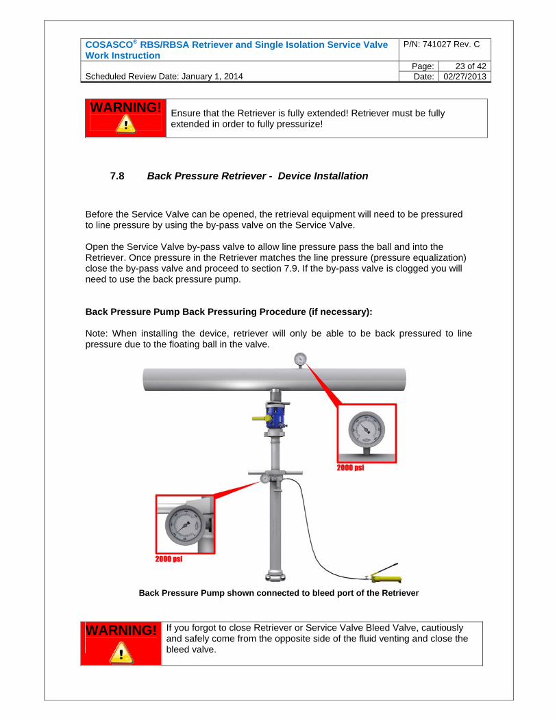
Before the Service Valve can be opened, the retrieval equipment will need to be pressured to line pressure by using the by-pass valve on the Service Valve. Open the Service Valve by-pass valve to allow line pressure pass the ball and into the Retriever. Once pressure in the Retriever matches the line pressure (pressure equalization) close the by-pass valve and proceed to section 7.9. If the by-pass valve is clogged you will need to use the back pressure pump. Back Pressure Pump Back Pressuring Procedure (if necessary): Note: When installing the device, retriever will only be able to be back pressured to line pressure due to the floating ball in the valve.
Back Pressure Pump shown connected to bleed port of the Retriever
WARNING!
Ensure that the Retriever is fully extended! Retriever must be fully extended in order to fully pressurize!
WARNING!
If you forgot to close Retriever or Service Valve Bleed Valve, cautiously and safely come from the opposite side of the fluid venting and close the bleed valve.
COSASCO® RBS/RBSA Retriever and Single Isolation Service Valve Work Instruction
P/N: 741027 Rev. C
Scheduled Review Date: January 1, 2014
Page: 24 of 42Date: 02/27/2013
1. Attach quick connect fitting to Service Valve bleed port or retrieval tool bleed port. 2. Attach high pressure hose to pump. Note - Pump, hose and all connections must be
pressure rated to same pressure rating of retrieval tool.
3. Connect other end of hose to retrieval tool or Service Valve (depending on orientation) via the quick connect coupling.
4. Fill pump reservoir with desired fluid, potable water will normally be used although hydraulic oil can be used if required.
5. Open the bleed valve on the Retriever and Service Valve bleed ports.
6. Begin actuating the pump. Once the Retriever and Service Valve are full (purged), close the bleed valve that does not have hose attached.
Keep pumping until pressure indicated on pump or retrieval tool pressure gauge is the same as the line operating pressure.
7. Once the desired pressure has been achieved, close the bleed valve on the retrieval tool
or Service Valve.
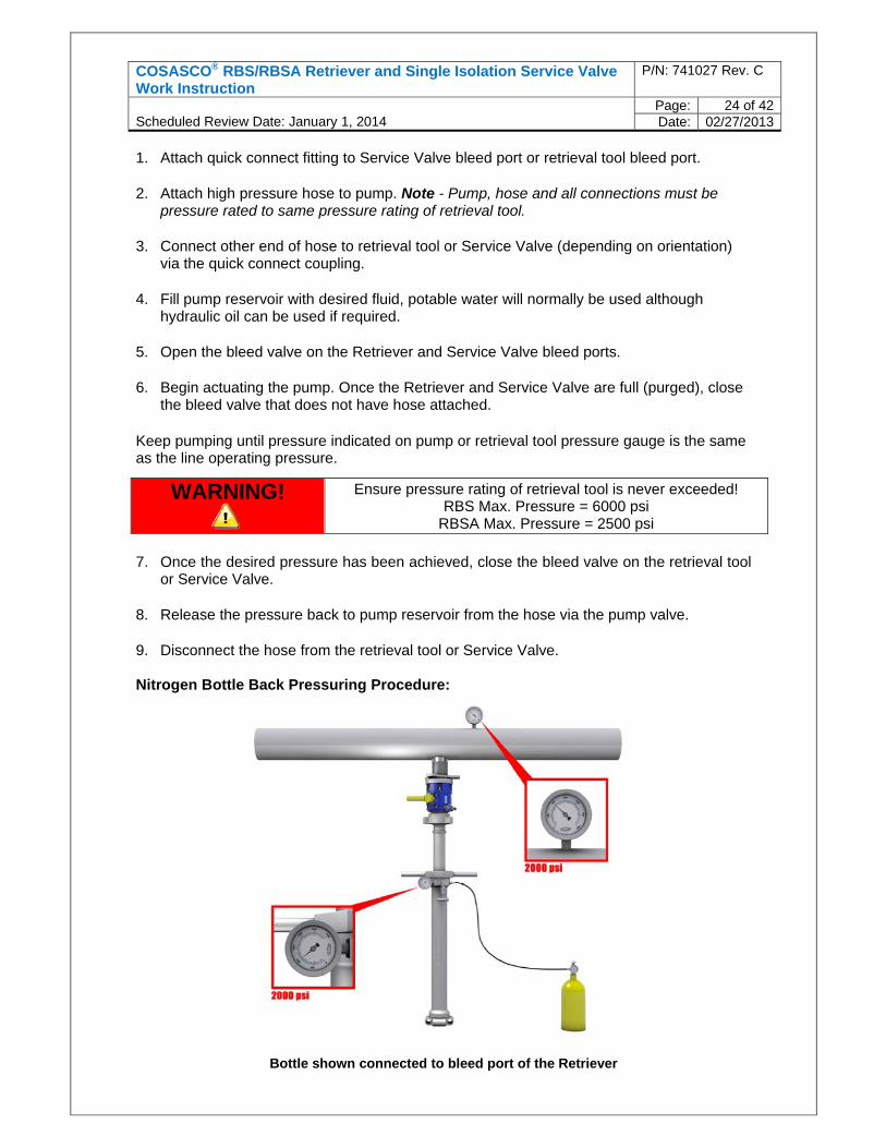
8. Release the pressure back to pump reservoir from the hose via the pump valve. 9. Disconnect the hose from the retrieval tool or Service Valve. Nitrogen Bottle Back Pressuring Procedure:
Bottle shown connected to bleed port of the Retriever
WARNING! Ensure pressure rating of retrieval tool is never exceeded! RBS Max. Pressure = 6000 psi
RBSA Max. Pressure = 2500 psi
COSASCO® RBS/RBSA Retriever and Single Isolation Service Valve Work Instruction
P/N: 741027 Rev. C
Scheduled Review Date: January 1, 2014
Page: 25 of 42Date: 02/27/2013
1. Connect a high pressure hose to the Retriever bleed valve or Service Valve bleed valve.
2. Nitrogen bottle connection. Connect the other end of the high pressure hose to the
nitrogen bottle outlet. It is recommended that:
The nitrogen bottle pressure be equal to the line pressure. The nitrogen bottle be equipped with a regulator. The nitrogen bottle be fitted with a bleed valve. (This is desirable to allow bleeding
down the hose after back pressuring is completed). 3. Nitrogen bottle control valve. Open the control valve and allow pressure build-up within
the hose to be equal with the line pressure.
4. Open the Retriever bleed valve or Service Valve bleed valve. 5. Allow the nitrogen pressure to enter the Retriever.
6. Once the desired pressure has been achieved, close the bleed valve on the retrieval tool
or Service Valve.
7. Close the nitrogen bottle control valve. Bleed off the pressure within the hose and
disconnect it from the Retriever bleed valve.
WARNING! Ensure pressure rating of retrieval tool is never exceeded! RBS Max. Pressure = 6000 psi
RBSA Max. Pressure = 2500 psi
IMPORTANT! Make sure both bleed valve on the retrieval tool and Service Valve are both closed in order to retain pressure when nitrogen bottle is disengaged!
IMPORTANT!
For all applications Retriever must be back pressured. Failure of the Retriever to pressurize is normally due to contamination or build-up of debris in the access fitting. The debris is trapped in the access fitting and pushes its way in while the plug assembly is being backed off, causing blockage and not allowing line pressure to enter the Service Valve and Retriever. Back pressuring the tool will prevent the internals of the retriever from being damaged when the plug is completely removed from the access fitting.
WARNING!
If you forgot to close Retriever or Service Valve Bleed Valve, cautiously and safely come from the opposite side of the fluid venting and close the bleed valve.
COSASCO® RBS/RBSA Retriever and Single Isolation Service Valve Work Instruction
P/N: 741027 Rev. C
Scheduled Review Date: January 1, 2014
Page: 26 of 42Date: 02/27/2013
7.9 Installation of the Carrier Plug
Once the equipment has been pressured to line pressure then the Service Valve can be opened to allow installation of the carrier plug and monitoring device.
1. Slowly open the Service Valve. 2. If used, remove the barrel clamp ensuring the weight of the outer barrel is being held by
an operator. Use a twisting motion and push / lower the extended Retriever towards the Service Valve until the 1st plug thread contacts first access fitting internal thread.
Step 2 Notes If at any stage during the execution of this step, excessive resistance or galling of the access fitting and carrier plug can be felt. Stop, remove the carrier plug and proceed to section 7.5, step 8 of this procedure. Once the Retriever is de-pressurized a thread tap will have to be run through the access fitting to clear/repair the internal threads, and the carrier plug threads will have to be checked for damage. See section 8 special tools and procedures for details on how to perform this operation.
If the carrier plug cannot be fully installed, one of the following problems may be occurring:
The device being installed is too long and is making contact with the back of the pipe before the plug is fully home. A shorter device will be required.
Thread damage to the internal thread of the access fitting or the carrier plug – see above note, the fitting will have to be thread tapped and a new carrier plug may be required.
Weld impingement not removed during installation of the access fitting, may be protruding in to the bore of the access fitting, preventing the passage of the device to be installed.
IMPORTANT! Do not use excessive force and be sure that the threads engage properly to prevent cross threading. Cross threading may require equipment to be left on the access fitting until the line is isolated.
WARNING!
If the plug assembly does not seat properly, it may be necessary to leave the Service Valve on the line until a later shut-down when repairs can be made. Do not remove until repairs have been made and plug assembly is securely seated, otherwise leakage may occur and pressure may not be held!
COSASCO® RBS/RBSA Retriever and Single Isolation Service Valve Work Instruction
P/N: 741027 Rev. C
Scheduled Review Date: January 1, 2014
Page: 27 of 42Date: 02/27/2013
3. Turn Retriever clockwise approx 14 turns until carrier plug primary seal seats in access
fitting. For bottom of line locations it will be necessary to keep the weight of the
Retriever supported upwards towards the Service Valve at all times during threading of the carrier plug in to the access fitting.
For side of line locations positive pressure should be applied on the Retriever towards the Service Valve during each rotation of the retrieval tool.
Tighten the carrier plug using sufficient force to obtain a seal. Do not fully compress the seal, as this will prevent orientation of the carrier plug.
4. Once the carrier plug is fully installed, release pressure from the Retriever in a controlled manner using either the Service Valve or Retriever bleed valve into a suitable container to catch fluids. When venting, particular notice should be paid to the location of gas detection systems and general ventilation of area. Systems with a known high H2S content must be vented via a diverter hose to a safe location, such as a closed drain, away from personnel. Step 4 Notes If pressure cannot be vented from the Retriever and valve, tighten the carrier plug further to compress the primary seal further. If pressure still cannot be fully vented, close the bleed valve. It will be necessary to remove the carrier plug to rectify the problem, which may be caused by one of the following:
The carrier plug is not fully installed – see notes in step 2 above. The primary packing seal is damaged and will have to be replaced. There is debris trapped between the primary packing and access fitting internal
sealing face, providing a leak path for pipe line product. The carrier plug will have to be removed and the access fitting seat reamer will have to be used, see section 8 special tools and procedures for details on how to perform this operation.
The access fitting internal sealing face is corroded or pitted. In this case an attempt can be made to use access fitting seat reamer, see section 8 special tools and procedures for details on how to perform this operation.
5. With bleeding of pipe line product from Retriever and Service Valve complete, close both
Retriever & Service Valve bleed valves and leave for 2 minutes to observe for pressure build up on the Retriever pressure gauge, and confirm that primary packing seal and probe seal if applicable are sealing.
6. Once it is confirmed that carrier plug seals are holding pressure, disconnect the socket adapter from the carrier plug hex by carrying out the following:
Top of line location - lift the Retriever up off of the carrier plug hex until it stops
(approximately 1”), while holding the Retriever up, turn the Retriever anticlockwise until it can be felt that the tool and carrier plug have disengaged. Take care when the Retriever is being turned that the socket does not engage the hex of the carrier plug.
Side of line location – pull the Retriever away from the valve (approx 1”) until it stops, then whilst keeping a slight pulling motion on the handles of the Retriever, turn the
COSASCO® RBS/RBSA Retriever and Single Isolation Service Valve Work Instruction
P/N: 741027 Rev. C
Scheduled Review Date: January 1, 2014
Page: 28 of 42Date: 02/27/2013
Retriever anti-clockwise until it can be felt that the socket adapter has unthreaded from the carrier plug. When turning the Retriever ensure that the socket does not engage the hex of the carrier plug.
7. Extend the Retriever to allow sufficient access to the hammer union of the retrieval tool.
It may be necessary to install a barrel clamp to support the outer barrel when in a top of line position. With one operator supporting the weight of the Retriever the other can loosen the hammer union of the retrieval tool, using a non sparking hammer, and unscrew from the Service Valve. Both operators can now lift the tool away from the Service Valve and place in a secure and stable location.
8. Using a non sparking hammer, loosen the hammer union of the Service Valve. In a top of line location there may be a small quantity of fluid in the valve cavity
(approximately 500ml), therefore ensure a sufficient means of capturing this fluid is available for when the valve is removed from the access fitting.
7.10 Carrier Plug Orientation & Access Fitting Cap Installation
1. Wipe the access fitting until clear of any residues. 2. If the installed device requires orienting with the pipe line flow direction, identify the mark
on the hex of the carrier plug and using a ring spanner turn the carrier plug clockwise until the mark is in the desired position to achieve orientation. If device does not require orientation use a ring spanner to tighten the carrier plug another ½ turn clockwise.
The following devices will require orientation:
Sand Probes Strip coupons Chemical injection quills and nozzles
3. Re-install the ½”ss pipe plug for solid carrier plugs or the plastic ½” pipe plug for hollow
plugs carrying probes not being connected to a Swagelok probe adapter. Only install the pipe plugs hand tight, and do not use any thread sealant.
4. Apply non metallic grease to the external threads and sealing face of the access fitting to
ensure adequate protection from corrosion and minimize the likelihood of the protective cover seizing in place at a later date.
IMPORTANT! Carefully remove Retriever from Service Valve! If product is liquid media a small amount of product may be lost at the disconnect junction!
WARNING!
DO NOT TURN THE PLUG ASSEMBLY HEX COUNTERCLOCKWISE TO ACHIEVE ORIENTATION! This will unseat the primary packing seal from the internal sealing face of the access fitting and leakage will occur!
COSASCO® RBS/RBSA Retriever and Single Isolation Service Valve Work Instruction
P/N: 741027 Rev. C
Scheduled Review Date: January 1, 2014
Page: 29 of 42Date: 02/27/2013
5. If a thread protecting cap is being installed, screw this on to the access fitting until hand tight. If the pipe is likely to experience excessive vibration the cap should be lightly tightened using a C spanner.
6. If a 2 hole pressure retaining cap is to be installed on the access fitting, check the
following prior to installation. O-ring is present inside the cap. Pressure gauge is installed and is in good condition and it also has thread sealant
applied at the ¼” NPT connection. Bleed valve is installed and is in good condition and it also has thread sealant applied
at the ¼” NPT connection. Thread the cap on to the access fitting and tighten lightly using a C ‘spanner.
7. If a 3 hole pressure retaining cover is being installed in conjunction with a Swagelok probe adapter follow all stages of step 6 then proceed as follows.
Apply thread sealant to the threaded section closest to the probe pin receiver holes
on the probe extension adapter.
Position the male / male threaded part of the adapter as close to the probe pin receiver holes as possible and the female Swage nut at the top of the adapter nearest the instrument connection pins
While holding the shaft in position, thread the male / male threaded section in to the ½” NPT hole on the cap. It may be necessary to remove the bleed valve on the cap for adequate access during this step. Tighten the threaded nut in to position using a suitable spanner. Note - it is important that the probe pins are not in contact with the probe adapter during tightening of the nut, otherwise damage to the probe pins can occur
Gently lower or push the shaft of the adapter towards the probe until the adapter makes contact with the probe pins
Turn the adapter in either direction until the locator pin on the probe and locator groove on the probe adapter are aligned, which should be obvious to feel. Once aligned the probe adapter can be pushed fully on to the probe pins. If the adapter cannot be easily pushed on to the probe pins, double check the alignment of the pins and adapter.
Once the probe pins are engaged with the adapter, thread the female Swage nut on to the threaded male section of the nut located in the cap. Tighten slowly to compress the metal olive, using a suitable open ended wrench – do not over tighten. Note - when tightening the female nut, observe the male threaded section to ensure it is not turning, if the male threaded section turns it means that the probe pins are being twisted and damaged, if necessary hold the threaded male section in place using another open ended wrench.
8. Ensure pressure retaining cap bleed return valve is closed 9. End of procedure
COSASCO® RBS/RBSA Retriever and Single Isolation Service Valve Work Instruction
P/N: 741027 Rev. C
Scheduled Review Date: January 1, 2014
Page: 30 of 42Date: 02/27/2013
8 SPECIAL TOOLS & PROCEDURES
The RBS/RBSA retrieval tool can be used with a number of ancillary tools and equipment which can aid with the servicing of an access fitting and may be essential in some circumstances as mentioned during earlier stages of this procedure. Below are some commonly used ancillary tools and the procedure for their safe and effective use.
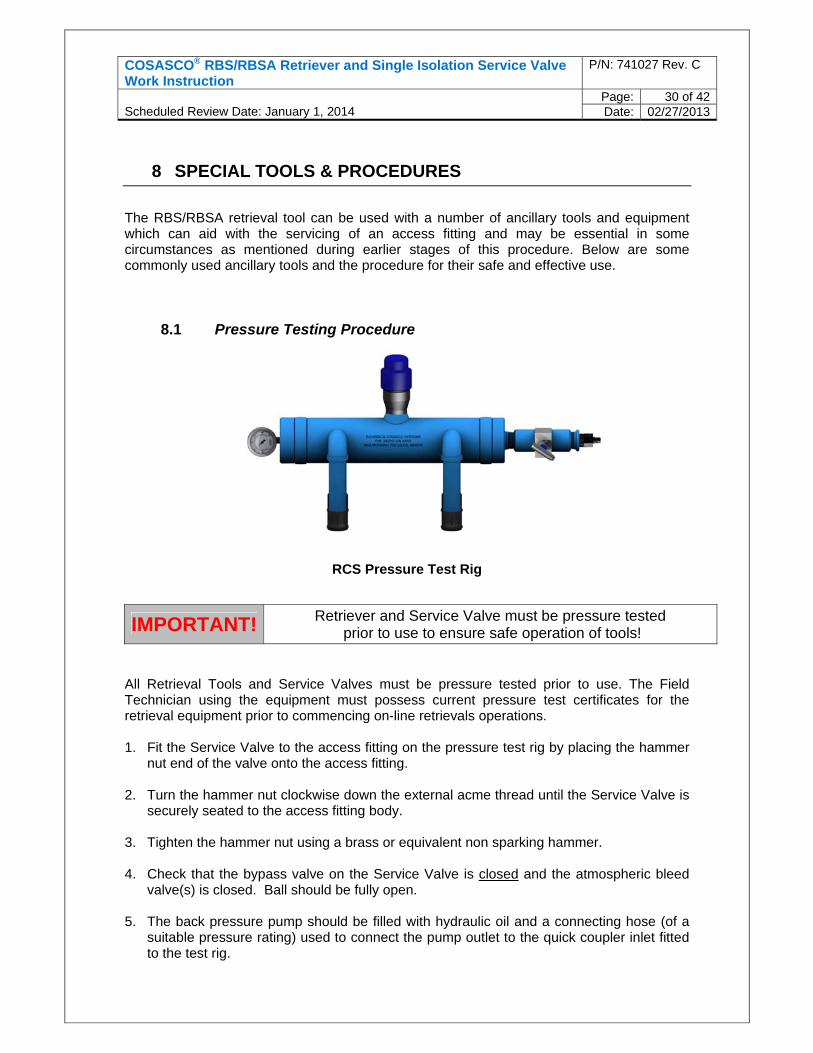
8.1 Pressure Testing Procedure
RCS Pressure Test Rig
All Retrieval Tools and Service Valves must be pressure tested prior to use. The Field Technician using the equipment must possess current pressure test certificates for the retrieval equipment prior to commencing on-line retrievals operations. 1. Fit the Service Valve to the access fitting on the pressure test rig by placing the hammer
nut end of the valve onto the access fitting.
2. Turn the hammer nut clockwise down the external acme thread until the Service Valve is securely seated to the access fitting body.
3. Tighten the hammer nut using a brass or equivalent non sparking hammer. 4. Check that the bypass valve on the Service Valve is closed and the atmospheric bleed
valve(s) is closed. Ball should be fully open.
5. The back pressure pump should be filled with hydraulic oil and a connecting hose (of a suitable pressure rating) used to connect the pump outlet to the quick coupler inlet fitted to the test rig.
IMPORTANT! Retriever and Service Valve must be pressure tested prior to use to ensure safe operation of tools!
COSASCO® RBS/RBSA Retriever and Single Isolation Service Valve Work Instruction
P/N: 741027 Rev. C
Scheduled Review Date: January 1, 2014
Page: 31 of 42Date: 02/27/2013
6. With the pump on "Pressure Hold” and at its low-pressure setting hand pump the oil into the pressure test rig.
7. Stop pumping once the oil level has passed the ball valve and close it. 8. Re-commence pumping and pressurize the assembly to the pressures stated in step 9.
Leave pressurized for 15 minutes during each stage and observe that there is no pressure drop on the pressure test rig gauge.
Note - There may be some drop in pressure during the 15 minute test period due to the compression of air still in the system and also due to oil being drawn back into the hand pump. If any pressure loss is due to leakage, this will be visible and immediately apparent.
9. Pressure test the equipment to the following pressures:
5% of pressure rating of equipment. 10% of pressure rating of equipment. 20% of pressure rating of equipment. 50% of pressure rating of equipment. 100% of pressure rating of equipment. 150% of pressure rating of equipment.
10. After completing all six tests in step 9, release pressure in the hydraulic pump.
11. After completion of the pressure test, ensure the ball valve is opened and place the
Retriever Tool onto the Service Valve. Turn the hammer nut union in a clockwise direction.
12. Tighten the hammer nut using a brass or equivalent non sparking hammer.
13. Ensure the bleed to atmosphere valve(s) on the Service Valve is closed and the Retriever bleed to atmosphere valve is opened.
14. With the hydraulic pump on "Pressure Hold” and at its low-pressure setting hand pump the oil through the Service Valve and into the Retrieval Tool, ensuring the isolating valve is fully opened.
15. Continue pumping until all air is displaced from the Retriever atmospheric bleed valve.
16. Continue pumping and during a pump action, close the Retriever atmospheric bleed valve.
17. Continue pumping and pressurize the assembly to the pressures stated in step 9. Leave pressurized for 15 minutes during each stage and observe that there is no pressure drop on the pressure test rig gauge. Note: There may be some drop in pressure during the 15 minute test period due to the compression of air still in the system and also due to water being drawn back into the hand pump. If any pressure loss is due to leakage, this will be visible and immediately apparent.
18. During each stage the Retriever requires to be stroked to check the integrity of the seals over the full travel of the outer barrel. .
COSASCO® RBS/RBSA Retriever and Single Isolation Service Valve Work Instruction
P/N: 741027 Rev. C
Scheduled Review Date: January 1, 2014
Page: 32 of 42Date: 02/27/2013
19. After completing all six tests in step 9, release pressure in the hydraulic pump Check both the pressure gauges on the test rig and retrieval tool are at zero and drain off any residual fluid trapped in the retrieval tool and Service Valve.
20. Remove both the retrieval tool and Service Valve from the test rig.
21. Complete a pressure test certificate for both the Retriever and the Service Valve and file these in the dedicated maintenance folder for each tool.
22. A scanned copy of the original should also be filed accordingly.
Note - There may be some drop in pressure during the 15 minute test period due to the compression of air still in the system and also due to water being drawn back into the hand pump. If any pressure loss is due to leakage, this will be visible and immediately apparent.
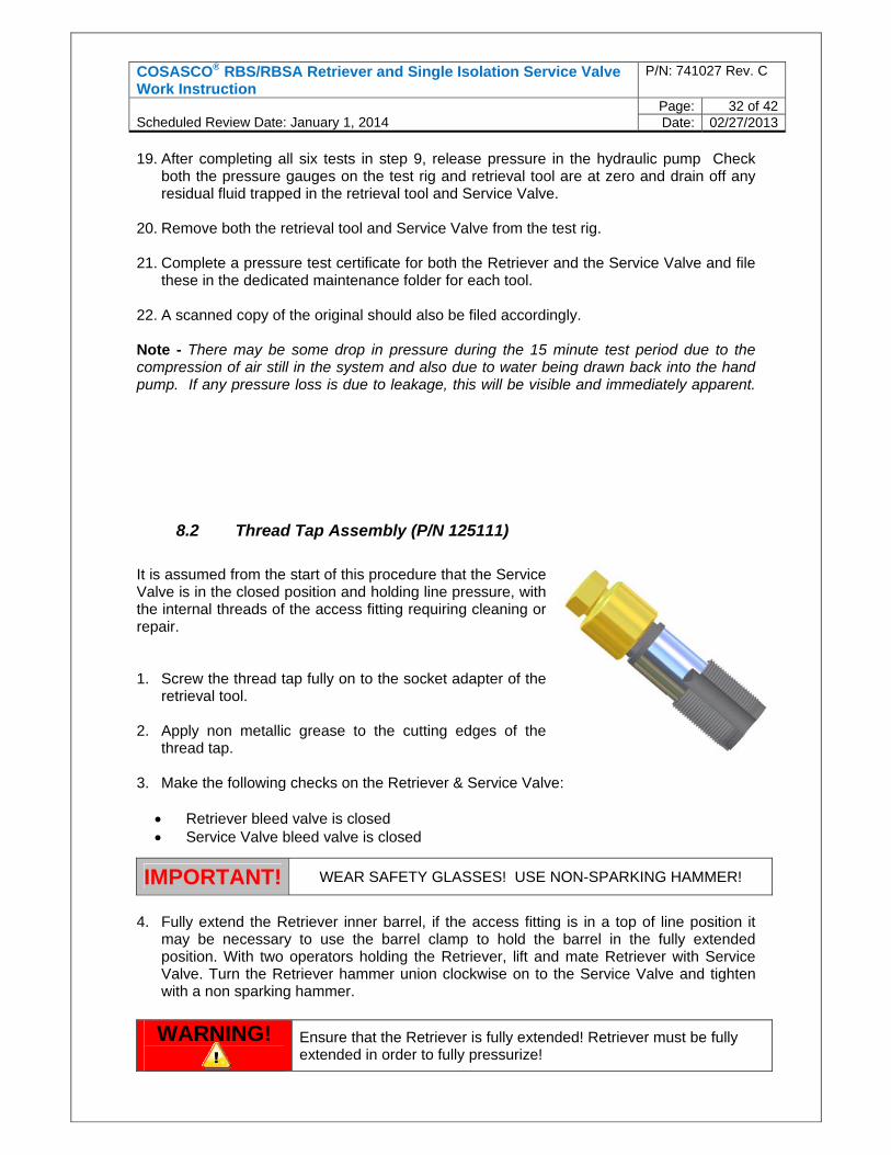
8.2 Thread Tap Assembly (P/N 125111)
It is assumed from the start of this procedure that the Service Valve is in the closed position and holding line pressure, with the internal threads of the access fitting requiring cleaning or repair. 1. Screw the thread tap fully on to the socket adapter of the
retrieval tool. 2. Apply non metallic grease to the cutting edges of the
thread tap. 3. Make the following checks on the Retriever & Service Valve:
Retriever bleed valve is closed Service Valve bleed valve is closed
4. Fully extend the Retriever inner barrel, if the access fitting is in a top of line position it
may be necessary to use the barrel clamp to hold the barrel in the fully extended position. With two operators holding the Retriever, lift and mate Retriever with Service Valve. Turn the Retriever hammer union clockwise on to the Service Valve and tighten with a non sparking hammer.
IMPORTANT! WEAR SAFETY GLASSES! USE NON-SPARKING HAMMER!
WARNING!
Ensure that the Retriever is fully extended! Retriever must be fully extended in order to fully pressurize!
COSASCO® RBS/RBSA Retriever and Single Isolation Service Valve Work Instruction
P/N: 741027 Rev. C
Scheduled Review Date: January 1, 2014
Page: 33 of 42Date: 02/27/2013
5. Back Pressure the Retriever (refer to Section 7.8) Back Pressure – Device Installation.
6. Slowly open the bypass valve on Service Valve.
7. Slowly open the Service Valve.
8. If used, remove the barrel clamp ensuring the weight of the outer barrel is being held by
an operator. Use twisting motion and push/lower the extended Retriever towards the Service Valve until the 1st thread tap cutting edge, contacts the first access fitting internal thread.
9. Slowly turn the Retriever clockwise approx until the thread tap is engaged with the first internal thread of the access fitting then continue turning clockwise for a further 15 turns. It may be necessary to work the tap clockwise and anti clockwise at times depending on how much damage or debris is encountered during insertion. Keep turning until tap runs smoothly over the fitting threads.
For bottom of line locations it will be necessary to keep the weight of the Retriever
supported upwards towards the Service Valve at all times during insertion of the thread tap in to the access fitting
For side of line locations, positive pressure should be applied on the Retriever towards the Service Valve during each rotation of the retrieval tool
10. Rotate Retriever anti-clockwise approx 15 turns to unscrew the thread plug from the
access fitting. For bottom of line locations it will be necessary to keep the weight of the Retriever
supported upwards towards the Service Valve at all times during un-threading of the thread plug from the access fitting, to ensure that the socket adapter does not accidentally unthread from the thread tap
For side of line locations positive pressure should be applied on the Retriever towards the Service Valve during each rotation of the retrieval tool, again to ensure that the socket adapter does not accidentally unthread from the thread tap
11. Fully extend Retriever, and if the fitting is in a top of line position it may be necessary to
fit a barrel clamp. 12. Close Service Valve to isolate line pressure. Note – at this stage the Retriever still
contains line pressure. 13. Release pressure from Retriever gradually using either the Service Valve or Retriever
bleed valve into a suitable container to catch fluids. When venting, particular notice should be paid to the location of gas detection systems and general ventilation of area. Note - Systems with a known high H2S content must be vented via a diverter hose to a safe location, such as a closed drain, away from personnel.
WARNING!
If you forgot to close Retriever or Service Valve Bleed Valve, cautiously and safely come from the opposite side of the fluid venting and close the bleed valve.
COSASCO® RBS/RBSA Retriever and Single Isolation Service Valve Work Instruction
P/N: 741027 Rev. C
Scheduled Review Date: January 1, 2014
Page: 34 of 42Date: 02/27/2013
14. Before removing the Retriever, close bleed valve on retrieval tool or Service Valve &
leave for 2 minutes to ensure the Service Valve is holding pressure. 15. While one operator is holding the Retriever in position, the other operator should use a
non sparking hammer to loosen the Retriever hammer union from Service Valve. Both operators can then remove the Retriever from the Service Valve. Carefully collapse the Retriever internal barrel to expose the thread tap, which can be now be removed from the retrieval tool. Ensure that the Retriever is located somewhere stable.
16. Check Retriever operation. Extend and collapse the Retriever inner barrel. If it is difficult to operate or feels contaminated with solids, rinse the internals with a suitable cleaning agent, or in some cases water is sufficient. Continue rinsing until operation of Retriever feels smooth. If flushing does not improve the function of the Retriever it will have to be stripped down and cleaned before continuing use.
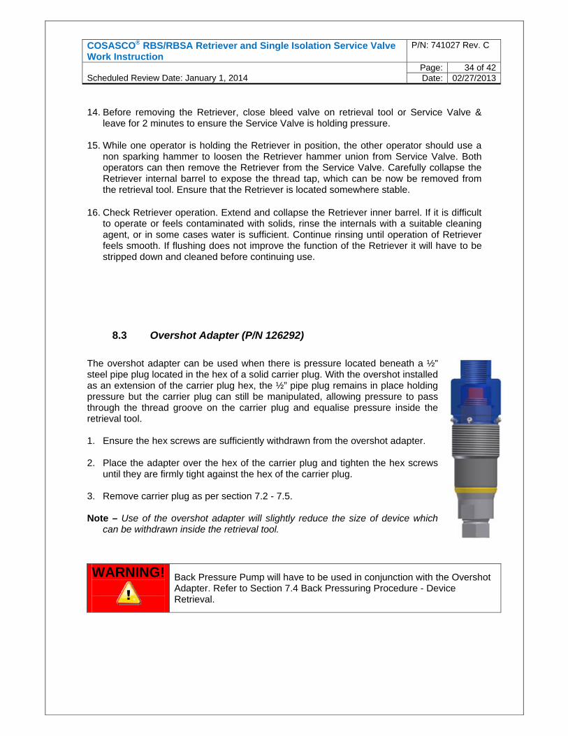
8.3 Overshot Adapter (P/N 126292)
The overshot adapter can be used when there is pressure located beneath a ½” steel pipe plug located in the hex of a solid carrier plug. With the overshot installed as an extension of the carrier plug hex, the ½” pipe plug remains in place holding pressure but the carrier plug can still be manipulated, allowing pressure to pass through the thread groove on the carrier plug and equalise pressure inside the retrieval tool. 1. Ensure the hex screws are sufficiently withdrawn from the overshot adapter. 2. Place the adapter over the hex of the carrier plug and tighten the hex screws
until they are firmly tight against the hex of the carrier plug.
3. Remove carrier plug as per section 7.2 - 7.5.
Note – Use of the overshot adapter will slightly reduce the size of device which can be withdrawn inside the retrieval tool.
WARNING!
Back Pressure Pump will have to be used in conjunction with the Overshot Adapter. Refer to Section 7.4 Back Pressuring Procedure - Device Retrieval.
COSASCO® RBS/RBSA Retriever and Single Isolation Service Valve Work Instruction
P/N: 741027 Rev. C
Scheduled Review Date: January 1, 2014
Page: 35 of 42Date: 02/27/2013
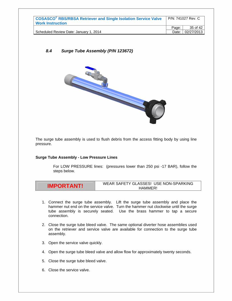
8.4 Surge Tube Assembly (P/N 123672)
The surge tube assembly is used to flush debris from the access fitting body by using line pressure. Surge Tube Assembly - Low Pressure Lines
For LOW PRESSURE lines: (pressures lower than 250 psi -17 BAR), follow the steps below.
1. Connect the surge tube assembly. Lift the surge tube assembly and place the
hammer nut end on the service valve. Turn the hammer nut clockwise until the surge tube assembly is securely seated. Use the brass hammer to tap a secure connection.
2. Close the surge tube bleed valve. The same optional diverter hose assemblies used
on the retriever and service valve are available for connection to the surge tube assembly.
3. Open the service valve quickly.
4. Open the surge tube bleed valve and allow flow for approximately twenty seconds.
5. Close the surge tube bleed valve.
6. Close the service valve.
IMPORTANT! WEAR SAFETY GLASSES! USE NON-SPARKING HAMMER!
COSASCO® RBS/RBSA Retriever and Single Isolation Service Valve Work Instruction
P/N: 741027 Rev. C
Scheduled Review Date: January 1, 2014
Page: 36 of 42Date: 02/27/2013
7. Open the surge tube bleed valve and allow the surge tube pressure to bleed off.
8. Close the surge tube valve.
9. Repeat steps 4 through 9 at least two more times.
Surge Tube Assembly - High Pressure Lines
For HIGH PRESSURE lines: (pressures higher than 250 psi -17 BAR), follow the steps below.
1. Connect the surge tube assembly. Lift the surge tube assembly and place the
hammer nut end on the service valve. Turn the hammer nut clockwise until the surge tube assembly is securely seated. Use the brass hammer to tap a secure connection.
2. Close the surge tube bleed valve. The same optional diverter hose assemblies used
on the retriever and service valve are available for connection to the surge tube assembly.
3. Open the service valve quickly. 4. Open the service valve equalizing valve. This will reduce the torque required to open
the service valve. 5. Open the service valve quickly and then close the service valve equalizing valve. 6. Open the surge tube bleed valve and allow flow for approximately twenty seconds. 7. Close and open the surge tube bleed valve - at least two more times and each time
allow flow for approximately twenty seconds. Each time the surge tube valve is in the open position, partially close and then fully open the service valve. This will help to remove solids or particles from the seat area or carrier.
8. Close all valves. Close the surge tube bleed valve, the service valve and the service
valve equalizing valve. 9. Open the surge tube bleed valve and allow the surge tube pressure to bleed-off. 10. Close the surge tube bleed valve. If the optional diverter hose assembly is being
used during the operation, it should be removed at this time.
11. Remove the surge tube assembly. Using the brass hammer, tap loose and fully
unscrew the surge tube hammer nut. Lift the surge tube assembly from the service valve.
IMPORTANT! WEAR SAFETY GLASSES! USE NON-SPARKING HAMMER!
IMPORTANT! WEAR SAFETY GLASSES! USE NON-SPARKING HAMMER!
COSASCO® RBS/RBSA Retriever and Single Isolation Service Valve Work Instruction
P/N: 741027 Rev. C
Scheduled Review Date: January 1, 2014
Page: 37 of 42Date: 02/27/2013
8.5 Thread Brush Assembly (P/N 125116)
The thread brush assembly is used to clean small amounts of debris from the access fitting body threads.
1. Attach the thread brush assembly to the socket adapter pilot threads.
2. Connect the retriever. Extend the retriever fully. Lift the retriever and place it onto the service valve. If the access fitting to be serviced is mounted on the top-of-line, install the wood clamp on the inner barrel to prevent the retriever outer barrel from collapsing of its own weight. Turn the hammer nut clockwise until the retriever is securely seated on the service valve. Use the brass hammer to tap a secure connection.
3. Back Pressure the Retriever (refer to Section 7.8) Back Pressure – Device installation.
4. Open the service valve equalizing valve and then open the service valve ball.
5. Collapse the retriever, remove the clamp and with a twisting, turning, sliding motion on the retriever outer barrel until the thread brush just barely contacts the access fitting body.
6. Brush the threads. Continue the twisting, turning, sliding motion of the brush, in a
clockwise direction, until it bottoms.
7. Retrieve the thread brush assembly. Beginning with a very slight clockwise rotation, pull the brush straight up and out of the access fitting body.
8. Extend the retriever.
9. Close the service valve and the service valve equalizing valve.
10. Bleed and remove the retriever. Open the retriever bleed valve and allow pressure to bleed off completely. Using the brass hammer, tap loose and fully unscrew the retriever hammer nut. Lift the retriever from the service valve.
11. Remove the thread brush assembly. Unscrew the thread brush assembly from the
socket adapter pilot.
IMPORTANT! WEAR SAFETY GLASSES! USE NON-SPARKING HAMMER!
IMPORTANT! WEAR SAFETY GLASSES! USE NON-SPARKING HAMMER!
COSASCO® RBS/RBSA Retriever and Single Isolation Service Valve Work Instruction
P/N: 741027 Rev. C
Scheduled Review Date: January 1, 2014
Page: 38 of 42Date: 02/27/2013
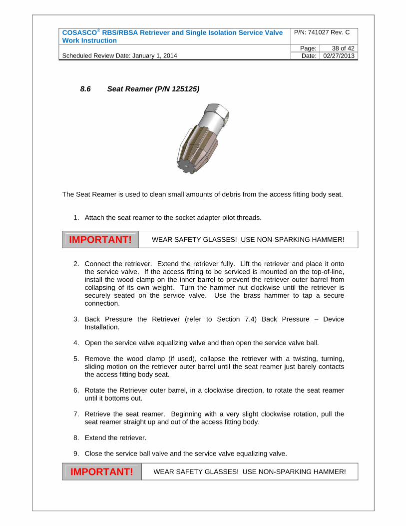
8.6 Seat Reamer (P/N 125125)
The Seat Reamer is used to clean small amounts of debris from the access fitting body seat.
1. Attach the seat reamer to the socket adapter pilot threads.
2. Connect the retriever. Extend the retriever fully. Lift the retriever and place it onto the service valve. If the access fitting to be serviced is mounted on the top-of-line, install the wood clamp on the inner barrel to prevent the retriever outer barrel from collapsing of its own weight. Turn the hammer nut clockwise until the retriever is securely seated on the service valve. Use the brass hammer to tap a secure connection.
3. Back Pressure the Retriever (refer to Section 7.4) Back Pressure – Device Installation.
4. Open the service valve equalizing valve and then open the service valve ball.
5. Remove the wood clamp (if used), collapse the retriever with a twisting, turning, sliding motion on the retriever outer barrel until the seat reamer just barely contacts the access fitting body seat.
6. Rotate the Retriever outer barrel, in a clockwise direction, to rotate the seat reamer until it bottoms out.
7. Retrieve the seat reamer. Beginning with a very slight clockwise rotation, pull the seat reamer straight up and out of the access fitting body.
8. Extend the retriever.
9. Close the service ball valve and the service valve equalizing valve.
IMPORTANT! WEAR SAFETY GLASSES! USE NON-SPARKING HAMMER!
IMPORTANT! WEAR SAFETY GLASSES! USE NON-SPARKING HAMMER!
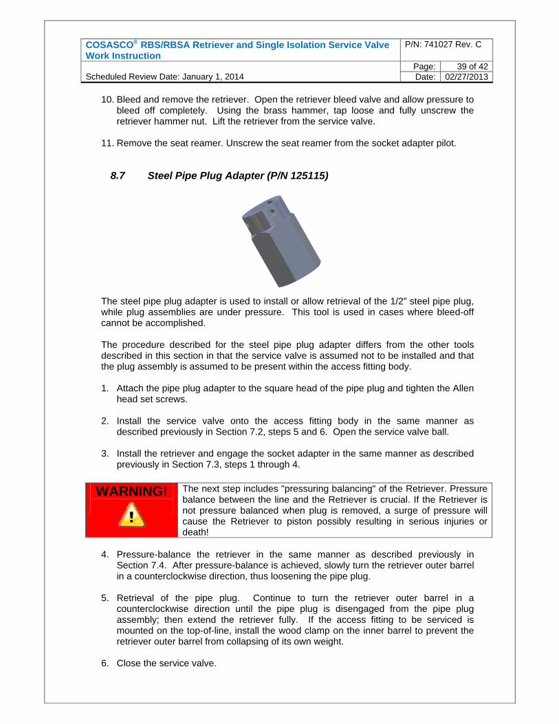
COSASCO® RBS/RBSA Retriever and Single Isolation Service Valve Work Instruction
P/N: 741027 Rev. C
Scheduled Review Date: January 1, 2014
Page: 39 of 42Date: 02/27/2013
10. Bleed and remove the retriever. Open the retriever bleed valve and allow pressure to bleed off completely. Using the brass hammer, tap loose and fully unscrew the retriever hammer nut. Lift the retriever from the service valve.
11. Remove the seat reamer. Unscrew the seat reamer from the socket adapter pilot.
8.7 Steel Pipe Plug Adapter (P/N 125115)
The steel pipe plug adapter is used to install or allow retrieval of the 1/2" steel pipe plug, while plug assemblies are under pressure. This tool is used in cases where bleed-off cannot be accomplished. The procedure described for the steel pipe plug adapter differs from the other tools described in this section in that the service valve is assumed not to be installed and that the plug assembly is assumed to be present within the access fitting body. 1. Attach the pipe plug adapter to the square head of the pipe plug and tighten the Allen
head set screws. 2. Install the service valve onto the access fitting body in the same manner as
described previously in Section 7.2, steps 5 and 6. Open the service valve ball. 3. Install the retriever and engage the socket adapter in the same manner as described
previously in Section 7.3, steps 1 through 4.
4. Pressure-balance the retriever in the same manner as described previously in
Section 7.4. After pressure-balance is achieved, slowly turn the retriever outer barrel in a counterclockwise direction, thus loosening the pipe plug.
5. Retrieval of the pipe plug. Continue to turn the retriever outer barrel in a
counterclockwise direction until the pipe plug is disengaged from the pipe plug assembly; then extend the retriever fully. If the access fitting to be serviced is mounted on the top-of-line, install the wood clamp on the inner barrel to prevent the retriever outer barrel from collapsing of its own weight.
6. Close the service valve.
WARNING!
The next step includes "pressuring balancing" of the Retriever. Pressure balance between the line and the Retriever is crucial. If the Retriever is not pressure balanced when plug is removed, a surge of pressure will cause the Retriever to piston possibly resulting in serious injuries or death!
COSASCO® RBS/RBSA Retriever and Single Isolation Service Valve Work Instruction
P/N: 741027 Rev. C
Scheduled Review Date: January 1, 2014
Page: 40 of 42Date: 02/27/2013
7. Open the bleed valve and bleed off pressure.
8. Using the brass hammer tap loose the retriever hammer nut and unscrew fully. Lift
the retriever from the service valve. Remove the wood clamp if it was installed. 9. Collapse the retriever to expose the socket adapter, the attached pipe plug adapter
and the pipe plug. Remove the adapter and the pipe plug from the socket adapter pilot.
10. Reinstall the retriever on the service valve and remove the solid plug assembly in the
same manner as described previously in Section 7.3, steps 1-13.
IMPORTANT! WEAR SAFETY GLASSES! USE NON-SPARKING HAMMER!

NOTES

Rohrback Cosasco Systems [email protected] www.cosasco.com