Embed Size (px)
Citation preview

Technology Today2011 ISSUE 2
HigHligHting RaytHeon’s tecHnology
Raytheon and the Environment Technologies to understand, monitor and preserve

A Message From Mark E. Russell Vice President of Engineering, Technology and Mission Assurance
2 2011 ISSUE 2 RAYTHEON TECHNOLOGY TODAY
Raytheon has a long history of providing solutions to complex environmental issues. Our
innovative sensing, communications, processing and visualization technologies quickly and
reliably provide decision makers with environmental information for land, sea and air.
This Environment issue of Technology Today features articles that demonstrate Raytheon’s leading
role in environmental science and engineering. We are engaged at all levels from basic science, to
managing environmental support activities and providing scientific instrumentation to academia
and government agencies, to integrating large-scale environmental monitoring systems.
Many of our world’s complex climate and environmental challenges are system-of-systems
problems, where Raytheon has deep technical expertise. We apply our domain knowledge to help
customers define climate issues, provide actionable information and develop tools to measure
outcomes. By successfully partnering with government, academia and industry, we have delivered
these capabilities from the remote regions of the Amazon to space.
As for initiatives related to sustainability, Raytheon has managed the National Science Foundation
U.S. Antarctic Program since 2000, supporting scientific activities while also minding the region’s
environmental preservation. Internally, as responsible citizens, we are employing clean energy and
conservation measures to minimize our energy footprint and our environmental impact.
In this issue’s Leaders Corner, Dan Crowley, president of Raytheon Network Centric Systems,
discusses leadership, customer engagement and NCS’ breadth of technology. Dan believes in turn-
ing challenges into opportunities by leveraging technology differentiators and providing new and
innovative products, solutions and services.
In Meet a Raytheon Leader, Brian Wells, vice president of Corporate Engineering, talks about pro-
moting synergy across the businesses, driving the use of common processes and encouraging the
use of environmentally-safe resources. An advocate for science, technology, engineering and math
(STEM) education, Brian led efforts to identify leverage points within the U.S. education system
to advance STEM.
The Events section highlights Raytheon’s participation in the 2011 Energy, Environment, Defense
and Security Conference, as well as our 2010 Excellence in Engineering and Technology Awards,
Excellence in Operations and Quality Awards, and Raytheon Six Sigma™ Awards.
We also graduated our first class of 22 Master of Science in systems engineering students from the
Johns Hopkins University. Our Special Interest and EYE on Technology sections complete this issue
with information about statistically-based test optimization and innovative technology developments.
Best regards,
Mark E. Russell
On the cover: The Moderate Resolution Imaging Spectroradiometer (MODIS) flies onboard NASA’s Aqua and Terra satellites as part of the Earth Observing System. Pictured is the Atlantic Ocean. Off the coast of France (bottom right) and the United Kingdom (top right), microscopic marine plants known as phytoplankton are blooming in the waters of the Atlantic Ocean, coloring the ocean blue and green. Visible/Infrared Imager Radiometer Suite (VIIRS), launched on Oct. 28, 2011, will replace MODIS and other environmental sensors. Photo image courtesy NASA.
View Technology Today online at: www.raytheon.com/technology_today INSIDE THIS ISSUE
Feature: Raytheon and the Environment
Overview: Technologies for Monitoring and Preserving our Environment 4
VIIRS Next-Generation Sensor for Weather/Climate Forecasting 7
Airborne Spectral Photometric Environmental Collection Technology 10
Raytheon’s Common Ground System for the Joint Polar Satellite System 12
Storm Trackers – Collaborative Adaptive Sensing of the Atmosphere 14
Raytheon Upgrades the Advanced Weather Interactive Processing System 18
Raytheon Completes Joint Environmental Toolkit Upgrades for Air Force Weather 20
Raytheon Delivers NextGen Weather Demonstrations to the FAA 22
The System for the Vigilance of the Amazon 24
A Collaborative Effort in a System-of-Systems: The Ocean Observatories Initiative 28
Operation Nanook – Arctic Monitoring and Prediction 32
Raytheon’s uFrame™ System Architecture to Provide Environmental Data Analysis 32
Environmental Technology on “The Ice” – Raytheon’s Antarctic Support Role 35
Raytheon Sustainability – Preserving the Environment for Future Generations 38
Raytheon Leaders
Leaders Corner: Q&A With President of NCS Dan Crowley 42
Meet a Raytheon Leader: Vice President of Engineering Brian Wells 44
EYE on Technology
Cognitive Computing Advancements Improve Information Gathering 46
Decentralized Cooperative Control for Autonomous UAVs 48
Man in the Mirror™ Uses Behavioral Analytics to Defend Against Cyber Attacks 50
People
First Raytheon Master of Science in Systems Engineering Class Graduates from Johns Hopkins University 51
Events
Energy, Environment, Defense and Security Conference 2011 52
2010 Raytheon Six Sigma™ Awards 53
2010 Excellence in Engineering and Technology Awards 54
2010 Excellence in Operations and Quality Awards 56
Special Interest
Design for Six Sigma Spotlight: Statistically-based Test Optimization 58
Patents 60
Technology Today is published by the Office of Engineering, Technology and Mission Assurance.
Vice President Mark E. Russell
Chief Technology Officer Bill Kiczuk
Managing Editor Cliff Drubin
Feature Editor Kenneth Kung
Senior Editors Corey Daniels Tom Georgon Eve Hofert
Art Director Debra Graham
Photography Don Bernstein Fran Brophy Rob Carlson Kathy Minette Dan Plumpton Dave Stana Bob Tures
Website Design Nick Miller
Publication Distribution Dolores Priest
Contributors Kate Emerson Melanie Plunkett Lindley Specht Frances Vandal
RAYTHEON TECHNOLOGY TODAY 2011 ISSUE 2 3

4 2011 ISSUE 2 RAYTHEON TECHNOLOGY TODAY
Feature
Raytheon’sEnvironmental Solutions
Technologies for Monitoring and Preserving our Environment
The feature articles in this issue demonstrate how Raytheon has played a leading role in environmental science and engi-neering across a broad range of activities. We are engaged in
basic science, managing environmental support activities, providing scientific instrumentation to academia and government agencies, and integrating large-scale environmental systems. Beyond this, we seek to be responsible citizens in the communities we live in by
implementing sound sustainable solutions to minimize our energy footprint and our environmental impact.
Raytheon participated in the worldwide conference on energy, en-vironment, defense and security (E2DS) May 2011 in Washington, D.C. This was the second gathering of representatives from defense companies, academia and government to collectively discuss how the vast resources and skills of the defense industry can be brought to bear on the critical environmental issues that affect our world.
Participants agreed that the magnitude of the issues we face is such that it takes the integrated and combined efforts of:
• Academia,tounderstandthebasicscience.
• Governments,tosupportanduniteinaddressingandleadingchange for the common good through research sponsorship, policy and treaties.
• Industry,toapplyitsconsiderableengineeringresourcestopro-mote and support scientific activities and to implement policy changes through application of its systems engineering expertise and technology resources.
You will read more about this conference and Raytheon’s sponsorship in our Events section.
RAYTHEON TECHNOLOGY TODAY 2011 ISSUE 2 5
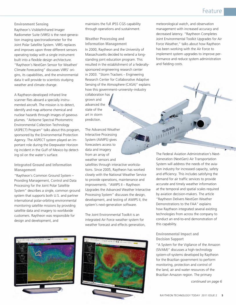
Environment Sensing Raytheon’s Visible/Infrared Imager Radiometer Suite (VIIRS) is the next-genera-tion imaging spectroradiometer for the Joint Polar Satellite System. VIIRS replaces and improves upon three different sensors operating today with a single instrument built into a flexible design architecture. “Raytheon’s NextGen Sensor for Weather/Climate Forecasting” discusses VIIRS’ ori-gins, its capabilities, and the environmental data it will provide to scientists studying weather and climate change.
A Raytheon-developed infrared line scanner flies aboard a specially instru-mented aircraft. The mission is to detect, identify and map airborne chemical and nuclear hazards through images of gaseous plumes. “Airborne Spectral Photometric Environmental Collection Technology (ASPECT) Program” talks about this program, sponsored by the Environmental Protection Agency. The ASPECT system played an im-portant role during the Deepwater Horizon rig incident in the Gulf of Mexico by detect-ing oil on the water’s surface.
Integrated Ground and Information Management “Raytheon’s Common Ground System – Providing Management, Control and Data Processing for the Joint Polar Satellite System” describes a single, common ground system that supports both U.S. and partner international polar-orbiting environmental monitoring satellite missions by providing satellite data and imagery to worldwide customers. Raytheon was responsible for design and development, and
maintains the full JPSS CGS capability through operations and sustainment.
Weather Processing and Information Management In 2000, Raytheon and the University of Massachusetts decided to extend a long-standing joint education program. This resulted in the establishment of a federally-sponsored engineering research center in 2003. “Storm Trackers – Engineering Research Center for Collaborative Adaptive Sensing of the Atmosphere (CASA)” explains how this government–university–industry collaboration has grown and advanced the state of the art in storm prediction.
The Advanced Weather Interactive Processing System (AWIPS) gives forecasters access to data and imagery from an array of weather sensors and satellites through interactive worksta-tions. Since 2005, Raytheon has worked closely with the National Weather Service to provide operations, maintenance and improvements. “AWIPS II – Raytheon Upgrades the Advanced Weather Interactive Processing System” discusses the design, development, and testing of AWIPS II, the system’s next-generation software.
The Joint Environmental Toolkit is an integrated Air Force weather system for weather forecast and effects generation,
meteorological watch, and observation management with increased accuracy and decreased latency. “Raytheon Completes Joint Environmental Toolkit Upgrades for Air Force Weather,” talks about how Raytheon has been working with the Air Force to implement system upgrades to improve per-formance and reduce system administration and fielding costs.
The Federal Aviation Administration’s Next-Generation (NextGen) Air Transportation System will address the needs of the avia-tion industry for increased capacity, safety and efficiency. This includes satisfying the demand for air traffic services to provide accurate and timely weather information at the temporal and spatial scales required by aviation decision-makers. The article “Raytheon Delivers NextGen Weather Demonstrations to the FAA” explains how Raytheon integrated several existing technologies from across the company to conduct an end-to-end demonstration of this capability.
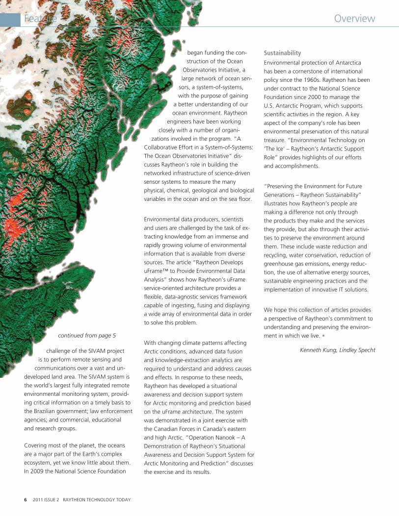
Environmental Impact and Decision Support “A System for the Vigilance of the Amazon (SIVAM)” discusses a high-technology system-of-systems developed by Raytheon for the Brazilian government to perform monitoring, protection and control of the land, air and water resources of the Brazilian Amazon region. The primary
continued on page 6
Feature
6 2011 ISSUE 2 RAYTHEON TECHNOLOGY TODAY
continued from page 5
challenge of the SIVAM project
is to perform remote sensing and
communications over a vast and un-
developed land area. The SIVAM system is
the world’s largest fully integrated remote
environmental monitoring system, provid-
ing critical information on a timely basis to
the Brazilian government; law enforcement
agencies; and commercial, educational
and research groups.
Covering most of the planet, the oceans
are a major part of the Earth’s complex
ecosystem, yet we know little about them.
In 2009 the National Science Foundation
began funding the con-
struction of the Ocean
Observatories Initiative, a
large network of ocean sen-
sors, a system-of-systems,
with the purpose of gaining
a better understanding of our
ocean environment. Raytheon
engineers have been working
closely with a number of organi-
zations involved in the program. “A
Collaborative Effort in a System-of-Systems:
The Ocean Observatories Initiative” dis-
cusses Raytheon’s role in building the
networked infrastructure of science-driven
sensor systems to measure the many
physical, chemical, geological and biological
variables in the ocean and on the sea floor.
Environmental data producers, scientists
and users are challenged by the task of ex-
tracting knowledge from an immense and
rapidly growing volume of environmental
information that is available from diverse
sources. The article “Raytheon Develops
uFrame™ to Provide Environmental Data
Analysis” shows how Raytheon’s uFrame
service-oriented architecture provides a
flexible, data-agnostic services framework
capable of ingesting, fusing and displaying
a wide array of environmental data in order
to solve this problem.
With changing climate patterns affecting
Arctic conditions, advanced data fusion
and knowledge-extraction analytics are
required to understand and address causes
and effects. In response to these needs,
Raytheon has developed a situational
awareness and decision support system
for Arctic monitoring and prediction based
on the uFrame architecture. The system
was demonstrated in a joint exercise with
the Canadian Forces in Canada’s eastern
and high Arctic. “Operation Nanook – A
Demonstration of Raytheon’s Situational
Awareness and Decision Support System for
Arctic Monitoring and Prediction” discusses
the exercise and its results.
Sustainability Environmental protection of Antarctica
has been a cornerstone of international
policy since the 1960s. Raytheon has been
under contract to the National Science
Foundation since 2000 to manage the
U.S. Antarctic Program, which supports
scientific activities in the region. A key
aspect of the company’s role has been
environmental preservation of this natural
treasure. “Environmental Technology on
‘The Ice’ – Raytheon’s Antarctic Support
Role” provides highlights of our efforts
and accomplishments.
“Preserving the Environment for Future
Generations – Raytheon Sustainability”
illustrates how Raytheon’s people are
making a difference not only through
the products they make and the services
they provide, but also through their activi-
ties to preserve the environment around
them. These include waste reduction and
recycling, water conservation, reduction of
greenhouse gas emissions, energy reduc-
tion, the use of alternative energy sources,
sustainable engineering practices and the
implementation of innovative IT solutions.
We hope this collection of articles provides
a perspective of Raytheon’s commitment to
understanding and preserving the environ-
ment in which we live. •
Kenneth Kung, Lindley Specht
Feature Overview
RAYTHEON TECHNOLOGY TODAY 2011 ISSUE 2 7
Feature
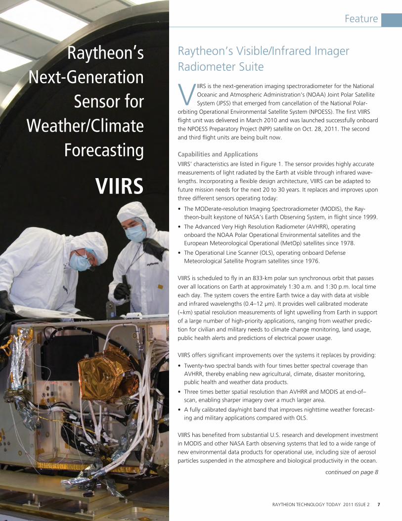
Raytheon’s Visible/Infrared Imager Radiometer Suite
VIIRS is the next-generation imaging spectroradiometer for the National Oceanic and Atmospheric Administration’s (NOAA) Joint Polar Satellite System (JPSS) that emerged from cancellation of the National Polar-
orbiting Operational Environmental Satellite System (NPOESS). The first VIIRS flight unit was delivered in March 2010 and was launched successfully onboard the NPOESS Preparatory Project (NPP) satellite on Oct. 28, 2011. The second and third flight units are being built now.
Capabilities and ApplicationsVIIRS’ characteristics are listed in Figure 1. The sensor provides highly accurate measurements of light radiated by the Earth at visible through infrared wave-lengths. Incorporating a flexible design architecture, VIIRS can be adapted to future mission needs for the next 20 to 30 years. It replaces and improves upon three different sensors operating today:
• TheMODerate-resolutionImagingSpectroradiometer(MODIS),theRay-theon-built keystone of NASA’s Earth Observing System, in flight since 1999.
• TheAdvancedVeryHighResolutionRadiometer(AVHRR),operating onboard the NOAA Polar Operational Environmental satellites and the European Meteorological Operational (MetOp) satellites since 1978.
• TheOperationalLineScanner(OLS),operatingonboardDefense Meteorological Satellite Program satellites since 1976.
VIIRS is scheduled to fly in an 833-km polar sun synchronous orbit that passes over all locations on Earth at approximately 1:30 a.m. and 1:30 p.m. local time each day. The system covers the entire Earth twice a day with data at visible and infrared wavelengths (0.4–12 μm). It provides well calibrated moderate (~km) spatial resolution measurements of light upwelling from Earth in support of a large number of high-priority applications, ranging from weather predic-tion for civilian and military needs to climate change monitoring, land usage, public health alerts and predictions of electrical power usage.
VIIRS offers significant improvements over the systems it replaces by providing:
• Twenty-twospectralbandswithfourtimesbetterspectralcoveragethanAVHRR, thereby enabling new agricultural, climate, disaster monitoring, public health and weather data products.
• ThreetimesbetterspatialresolutionthanAVHRRandMODISatend-of–scan, enabling sharper imagery over a much larger area.
• Afullycalibratedday/nightbandthatimprovesnighttimeweatherforecast-ing and military applications compared with OLS.
VIIRS has benefited from substantial U.S. research and development investment in MODIS and other NASA Earth observing systems that led to a wide range of new environmental data products for operational use, including size of aerosol particles suspended in the atmosphere and biological productivity in the ocean.
continued on page 8
Raytheon’s Next-Generation
Sensor for Weather/Climate
Forecasting
VIIRS

8 2011 ISSUE 2 RAYTHEON TECHNOLOGY TODAY
Feature
Continued from page 7
System Description and OperationA key to the VIIRS architecture is a rotat-ing telescope assembly that provides the flexibility needed to meet a diverse set of requirements for multispectral imaging spectroradiometry and low light level day/night imaging. Advantages of the rotat-ing telescope design relative to scan mirror based systems like AVHRR and MODIS include:
• Bettercontrolofstraylight.
• Smallerrangeinangleofincidenceoflight on the fore optics to reduce image distortion.
• ImmunitytoimagerotationseeninAVHRR as the scan moves out from nadir.
• Betterprotectionfromcontaminationanddegradation over time because all of the optical elements are placed deep inside the instrument housing.
Design, fabrication and testing of the rotating telescope assembly responded successfully to challenging stray light and instrument background requirements to produce a well understood high-perfor-mance subsystem. The result is an imager that is ready to provide high fidelity data for the international science, weather and other environmental data product communities with much better spatial resolution at end-of-scan than AVHRR and MODIS.
The rotating telescope assembly is followed by a fixed telescope along with other back-end optics that image the scene and separate light into three focal planes with filters that define each spectral band. A cryoradiator radiates heat from the infrared detector arrays to deep space to maintain a stable detector operating temperature as low as 78 Kelvin. The focal plane interface electronics carry signals from the detector arrays to the externally mounted Electronics Module. The EM synchronizes the rotating telescope assembly with a rotating flat mir-ror, making it possible to image the scene onto the detector arrays without image rotation. The EM also provides onboard processing of detector samples to enable a nearly constant pixel size across the en-tire scan, data compression, processing of operational and housekeeping data, and formatting of these data into the consul-tative committee on space data systems (CCSDS) format. The EM also communicates via a data bus with the spacecraft, to pro-vide VIIRS operational data and telemetry, and to receive commands, spacecraft telem-etry and software uploads. A fault tolerant design enables long mission life.
VIIRS has an on-board calibration subsystem consisting of a carefully stabilized blackbody source to provide a reference signal for the emissive infrared bands and a diffuser to provide a reference for bands domi-nated by reflected sunlight. VIIRS includes a monitor to detect changes in the optical
Orbit: 833 km polar sun-synchronousSwath: >3,000 km (±56 degrees about nadir)Scanning: Rotating telescope with dual-sided, half-angle mirrorSize: 135 x 148 x 89 cm3
Spectral Coverage: 0.4 to 12.5 µmNumber of Bands: Visible/Near Infrared: 9, plus day/night band Mid-wave Infrared: 8 Long-wave Infrared: 4Resolution: Radiometric (16 bands): 0.742 km nadir, 1.6 km EOS Imaging (5 bands): 0.371 km nadir, 0.8 km EOS Day/Night Band: 0.742 km constant across scanMass: 270 kgPower: 170 WData Rate: 8 Mbps (avg.) / 10.5 Mbps (max.)
Flight Units 1 and 2 Instrument Specifications
Figure 1. High level VIIRS Flight Unit 1 and Flight Unit 2 instrument characteristics with photo of FU1 being integrated onto the NPP spacecraft at Ball Aerospace. Photo courtesy Ball Aerospace.

RAYTHEON TECHNOLOGY TODAY 2011 ISSUE 2 9
VIIRS
characteristics of the solar diffuser over time. The VIIRS calibration subsystem has a rich MODIS heritage — a key to maintaining continuity with data from the MODIS instruments onboard the Terra and Aqua satellites.
Scientists and weather forecasters have been preparing to use VIIRS data for years. A group at the Naval Research Laboratory in Monterey, Calif., has created a tool called NextSat that simulates VIIRS data and the near real time creation of environmental data products by combining measurements from MODIS, AVHRR, OLS and the U.S. geosynchronous orbit environmental monitoring system with new processing and display methods. Figure 2 shows an example of NextSat output that illustrates the intricate detail expected from VIIRS
data and the usefulness of this wealth of information for distinguishing artificial phe-nomena such as contrails from naturally occurring clouds.
VIIRS will continue to improve upon the record of environmental data used by scien-tists to measure climate change. It is the primary instrument for 22 of 38 environ-mental data records to be collected by the JPSS for weather forecasting, sea surface temperature, ocean color, land use, biomass fires, aerosols and cloud top properties. The enhanced imagery provided by VIIRS will expand the environmental data record and improve weather forecasting and climate
monitoring for generations. •
Jeffery J. Puschell
Dr. Jeff Puschell Principal Engineering Fellow, SAS
With greater than
31 years of experi-
ence in developing
advanced technol-
ogy infrared and
visible wavelength
systems for a variety
of operational and
research applications, Dr. Jeff Puschell is an
internationally recognized expert in the sys-
tem engineering of space-based imaging and
remote sensing systems.
Puschell’s experience is broadly based and
includes: leading and contributing to the
development of visible-infrared instruments
for space-based environmental remote sens-
ing; developing and field testing of laser-based
communication and remote sensing systems;
and building and using millimeter, infrared,
visible and ultraviolet wavelength instrumenta-
tion for ground-based astronomy. Puschell is
involved early in the development process. He
works directly with key scientific and engineer-
ing members of customer organizations to
understand their emerging mission needs, and
he provides effective sensor system designs and
performance specifications.
“In the mid 1990s, I jumped at the opportunity
to work on operational remote sensing systems
for weather forecasting, because it was such a
good fit for my background and it provided
a chance to work on systems that save lives,”
states Puschell. “These systems provide vitally
needed situational awareness for U.S. forces
around the world, and they benefit humanity
by providing information on severe weather,
biological productivity, natural disasters and
climate trends. I’m excited by the possibility
of contributing to a better world through our
technology and innovation, and by
the opportunity to impact the future and bene-
fit our nation with sensor systems that provide
information to enable deeper understanding
and better informed government policies.”
ENGINEERING PROFILE
Figure 2. The Naval Research Lab NextSat tool uses data from existing systems like MODIS to illustrate how information-rich VIIRS data will enable analysts to recognize many details in scenes such as contrails and water clarity that cannot be recognized today with the operational AVHRR and OLS systems. Background image courtesy NASA.
10 2011 ISSUE 2 RAYTHEON TECHNOLOGY TODAY
Feature
Airborne Spectral Photometric Environmental Collection Technology Program
A partnership between the U.S. Environmental Protection Agency and the U.S. Department of
Defense has led to the development of a suite of remote sensing instruments mounted in a small aircraft that can obtain detailed chemical information from a safe distance. Airborne Spectral Photometric Environmental Collection Technology (ASPECT) is an emergency response sensor package operated by the EPA. It provides first responders with information on possi-ble chemical releases. The system is capable of accurately detecting and quantifying concentrations of specific chemicals in the air at levels that may present human health threats.
The EPA supports emergency first respond-ers, such as local fire departments and hazardous materials teams, with actionable information in a form that is timely, useful and compatible with existing communica-tion infrastructures. The ASPECT system, a rapid response system with requirements to be airborne in less than one hour, pro-vides airborne chemical measurements and imagery directly to the local incident commander. ASPECT integrates infrared sensors that provide standoff detection sensing of chemical plumes, automated near real-time data processing, aerial photography and data communication via satellite. The image results are overlaid on standard maps and viewed using the Google EarthTM mapping service.
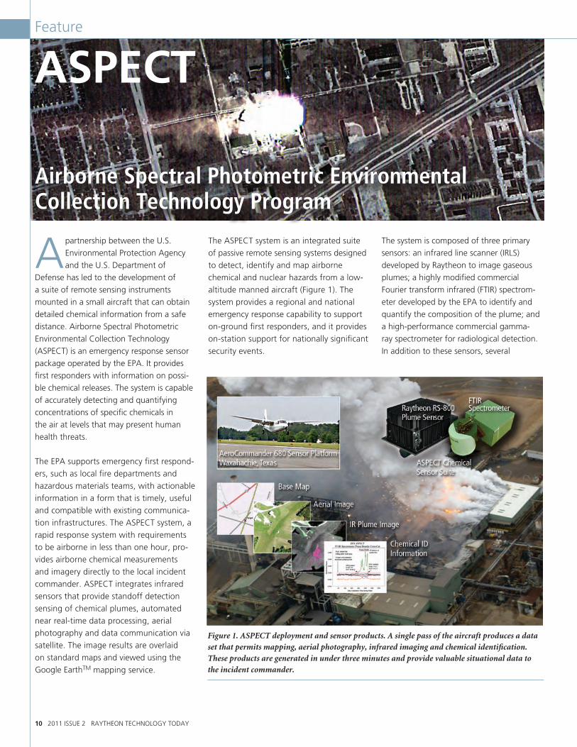
The ASPECT system is an integrated suite of passive remote sensing systems designed to detect, identify and map airborne chemical and nuclear hazards from a low-altitude manned aircraft (Figure 1). The system provides a regional and national emergency response capability to support on-ground first responders, and it provides on-station support for nationally significant security events.
The system is composed of three primary sensors: an infrared line scanner (IRLS) developed by Raytheon to image gaseous plumes; a highly modified commercial Fourier transform infrared (FTIR) spectrom-eter developed by the EPA to identify and quantify the composition of the plume; and a high-performance commercial gamma-ray spectrometer for radiological detection. In addition to these sensors, several
Figure 1. ASPECT deployment and sensor products. A single pass of the aircraft produces a data set that permits mapping, aerial photography, infrared imaging and chemical identification. These products are generated in under three minutes and provide valuable situational data to the incident commander.
ASPECT

RAYTHEON TECHNOLOGY TODAY 2011 ISSUE 2 11
Feature
high-resolution color digital cameras pro-vide high-quality context imagery. All data streams are registered to map coordinates using global positioning satellite data.
This uniquely instrumented aircraft, based on the civilian twin turboprop Aerocommander, is used to monitor air-borne environment conditions prior to and during significant events. Since 1998, ASPECT has been used by seven of the 10 EPA regions for more than 100 separate response actions, including:
• Forty-oneemergencyresponses.
• SevenDepartmentofHomelandSecurity(DHS) special event activity rating deployments.
• NineDHSNationalSpecialSecurityEvent deployments.
• FiveFederalEmergencyManagementAgency activations.
• Twelvespecialprojects.
These responses include:
• Monitoringthe2002WinterOlympicGames in Salt Lake City, Utah.
• Searchingfordangerousrocketfuelanddebris during the Columbia shuttle recovery.
• Assessingandmonitoringdamagefromhurricanes Rita, Katrina and Ike (Figure 2).
• PerformingoverheadsecurityforRoseBowls® 2008–2011, Super Bowl® XLV, and the 2008 presidential inauguration.
• Monitoringthe2010gulfoilspill (Figure 3).
• MonitoringairqualityinthevicinityofLos Alamos during the summer 2011 New Mexico wild fires.
At present, the EPA and Raytheon are work-ing together to develop a next-generation IRLS sensor that will significantly increase the system’s detection and identification ca-pabilities. This effort has been ongoing since
2006, and fielding is anticipated in 2012. •
Randall Zywicki
Figure 2. Hurricane Rita response - ammonia leak.
Figure 3. During the Deepwater Horizon rig incident in the Gulf of Mexico, the ASPECT system — which collected data in response to the oil spill — was the only technology that the EPA deemed reliable at detecting oil on the water’s surface. This achievement received congressional recognition and support during the oil disaster.

12 2011 ISSUE 2 RAYTHEON TECHNOLOGY TODAY
Feature
Raytheon’s Common Ground System – Providing Management, Control and Data Processing for the Joint Polar Satellite System
The reliability of weather forecasting that we have become dependent upon today is possible because of
data inputs to the National Weather Service forecasting models from the U.S. polar- orbiting environmental satellites. Greater than 98 percent of the inputs to the com-puters that forecast the world’s weather come from satellites.
NASA, under direction from the National Oceanic and Atmospheric Administration (NOAA), is working to maintain and en-hance our nation’s weather prediction capability by developing the Joint Polar Satellite System (JPSS). Raytheon plays a crucial role in the JPSS program, serving as the developer and operator of the Common Ground System (CGS) that receives and processes the science data and operates the satellites on behalf of NOAA.
JPSS will replace the current national polar-orbiting environmental satellite systems: NOAA’s Polar-Orbiting Environmental Satellite (POES), the U.S. Department of Defense’s (DoD) Defense Meteorological Satellite Program, and NASA’s Earth Observing System (EOS). All will be retired within this decade. Figure 1 compares JPSS and heritage system capabilities.
National Polar-orbiting Operational Environmental Satellite System (NPOESS) Preparatory ProjectAs a precursor to JPSS, NASA launched the NPOESS Preparatory Project (NPP) mission on Oct. 28, 2011. NPP reduces risk by providing an opportunity to exercise and validate new instruments and process-ing algorithms, and by demonstrating and validating aspects of the JPSS command, control, communications and ground pro-cessing capabilities prior to launching the first JPSS spacecraft, expected in 2016. NPP also provides NASA with continuing measurements of global change parameters after EOS missions, Terra and Aqua, reach end-of-life. Furthermore, NPP has taken on more of an operational role as the need to replace aging legacy on-orbit polar envi-ronmental sensing capabilities and missions becomes more urgent.
Joint Polar Satellite System JPSS will carry improved imaging and sound-ing sensors, increasing NOAA and DoD capabilities to monitor global environmen-tal conditions and collect and disseminate data related to the weather, atmosphere, oceans, land and the near-space environ-ment shown in Figure 2. The polar orbiters
are able to monitor the entire planet and provide data for long-range weather and climate forecasts.
Data and imagery obtained from JPSS will increase the timeliness and accuracy of pub-lic warnings and forecasts of climate and weather events, thus reducing the potential loss of human life and property, and mini-mizing the social and economic impact.
Raytheon’s JPSS Common Ground System (CGS)The CGS offers a single common ground system to support polar-orbiting environ-mental monitoring satellite missions for both the U.S. and its international partners. Raytheon is responsible for the full JPSS CGS capability, from design and develop-ment through operations and sustainment.
DMSPDefense Meteorological
Satellite Program
1960−2010 2000−2014 2014−2025+
POESPolar-Orbiting OperationalEnvironmental Satellites
Sensor data rates: 1.5 MbpsData latency: 100−150 min.
Sensor data rates: 15 MbpsData latency: 100−180 min.Data availability: 98%Ground revisit time: 12 hrs
Sensor data rates: 20 MbpsData latency: 28 min.Data availability: 99.95%Autonomy capability: 60 daysSelective encryption/deniabilityGround revisit time: 4−6 hrs
1.7 Gigabytes per day
6.3 Gigabytes per day
NPPNPOESS Preparatory
Project
EOSEarth Observing
System
JPSSJoint Polar
Satellite System
DWSSDefense WeatherSatellite System
2.4 Terabytes per day 5.4 Terabytes per day
2.6 Terabytes per day
Figure 1. The evolution of JPSS and its capabilities from current polar-orbiting environmental satellite systems that are approaching end-of-life.
Figure 2. NOAA’s societal benefits areas.
Natural and Human Induced Disasters
WaterResources
Ecosystems
HumanHealth andWell Being
EnergyResources
WeatherInformation,Forecasting
and Warning
SustainableAgricultureandDesertification
ClimateVariabilityand Change
Oceans
RAYTHEON TECHNOLOGY TODAY 2011 ISSUE 2 13
Feature
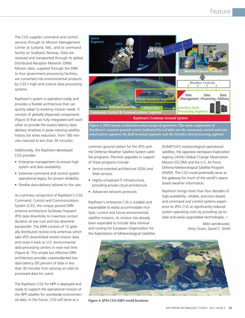
The CGS supplies command and control services through its Mission Management Center at Suitland, Md., and its command facility on Svalbard, Norway. Data are received and transported through its global Distributed Receptor Network (DRN). Mission data, supplied through the DRN to four government processing facilities, are converted into environmental products by CGS’s high-end science data processing systems.
Raytheon’s system is operation-ready and provides a flexible architecture that can quickly adapt to evolving mission needs. It consists of globally-dispersed components (Figure 3) that are fully integrated with each other to provide the lowest-latency data delivery timelines in polar-orbiting satellite history (six times reduction, from 180 min-utes reduced to less than 30 minutes).
Additionally, the Raytheon-developed CGS provides:
• Enterprisemanagementtoensurehighsystem and data availability.
• Extensivecommandandcontrolsystemoperational legacy for proven reliability.
• Flexibledata-deliverytailoredtotheuser.
As a primary component of Raytheon’s CGS Command, Control and Communications System (C3S), the unique ground DRN antenna architecture facilitates frequent JPSS data downlinks to maximize contact duration at low cost and low downlink bandwidth. The DRN consists of 15 glob-ally distributed receive-only antennas which take JPSS downlinked stored mission data and route it back to U.S. environmental data-processing centers in near-real time (Figure 4). This simple but effective DRN architecture provides unprecedented low data latency (95 percent of data in less than 30 minutes from sensing on orbit to processed data for users).
The Raytheon CGS for NPP is deployed and ready to support the operational mission of the NPP satellite for worldwide environmen-tal data. In the future, CGS will serve as a
common ground station for the JPSS and the Defense Weather Satellite System satel-lite programs. Planned upgrades in support of these programs include:
• Service-orientedarchitecture(SOA)andWeb services.
• Highly-virtualizedITinfrastructure, providing private cloud architecture.
• Advancednetworkprotocols.
Raytheon’s enterprise C3S is scalable and expandable to easily accommodate mul-tiple, current and future environmental satellite missions. Its mission has already been expanded to include data retrieval and routing for European Organization for the Exploitation of Meteorological Satellites
(EUMETSAT) meteorological operational satellites, the Japanese Aerospace Exploration Agency (JAXA) Global Change Observation Mission (GCOM) and the U.S. Air Force Defense Meteorological Satellite Program (DMSP). The CGS could potentially serve as the gateway for much of the world’s space-based weather information.
Raytheon brings more than four decades of high-availability, reliable, precision-based, and command and control systems experi-ence to JPSS CGS at significantly reduced system operating costs by providing up-to-
date and easily-upgradable technologies. •
Mike Jamilkowski, Kerry Grant, David C. Smith
Figure 3. JPSS system architecture and concept of operation. The main components of Raytheon’s common ground system (indicated by red tabs) are the command, control and com-munications segment; the field terminal segment; and the interface data processing segment.
Figure 4. JPSS CGS DRN world locations.
SpaceSegment
DWSS JPSS
NPP
Field Terminal Segment
Interface DataProcessing Segment
Weather Centrals
Weather/Climate Products
Command, Control & Communications Segment
Raytheon’s Common Ground System
Mission Data15 Globally Distributed Receptor Sites
JPSS
NPP
Data Data Data>Management >Processing >Delivery
14 2011 ISSUE 2 RAYTHEON TECHNOLOGY TODAY
Feature
Storm Trackers – Engineering Research Center for Collaborative Adaptive Sensing of the Atmosphere
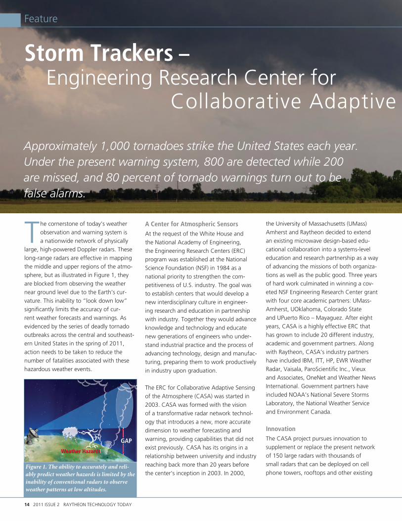
The cornerstone of today’s weather observation and warning system is a nationwide network of physically
large, high-powered Doppler radars. These long-range radars are effective in mapping the middle and upper regions of the atmo-sphere, but as illustrated in Figure 1, they are blocked from observing the weather near ground level due to the Earth’s cur-vature. This inability to “look down low” significantly limits the accuracy of cur-rent weather forecasts and warnings. As evidenced by the series of deadly tornado outbreaks across the central and southeast-ern United States in the spring of 2011, action needs to be taken to reduce the number of fatalities associated with these hazardous weather events.
A Center for Atmospheric SensorsAt the request of the White House and the National Academy of Engineering, the Engineering Research Centers (ERC) program was established at the National Science Foundation (NSF) in 1984 as a national priority to strengthen the com-petitiveness of U.S. industry. The goal was to establish centers that would develop a new interdisciplinary culture in engineer-ing research and education in partnership with industry. Together they would advance knowledge and technology and educate new generations of engineers who under-stand industrial practice and the process of advancing technology, design and manufac-turing, preparing them to work productively in industry upon graduation.
The ERC for Collaborative Adaptive Sensing of the Atmosphere (CASA) was started in 2003. CASA was formed with the vision of a transformative radar network technol-ogy that introduces a new, more accurate dimension to weather forecasting and warning, providing capabilities that did not exist previously. CASA has its origins in a relationship between university and industry reaching back more than 20 years before the center’s inception in 2003. In 2000,
the University of Massachusetts (UMass) Amherst and Raytheon decided to extend an existing microwave design-based edu-cational collaboration into a systems-level education and research partnership as a way of advancing the missions of both organiza-tions as well as the public good. Three years of hard work culminated in winning a cov-eted NSF Engineering Research Center grant with four core academic partners: UMass-Amherst, UOklahoma, Colorado State and UPuerto Rico – Mayaguez. After eight years, CASA is a highly effective ERC that has grown to include 20 different industry, academic and government partners. Along with Raytheon, CASA’s industry partners have included IBM, ITT, HP, EWR Weather Radar, Vaisala, ParoScientific Inc., Vieux and Associates, OneNet and Weather News International. Government partners have included NOAA’s National Severe Storms Laboratory, the National Weather Service and Environment Canada.
InnovationThe CASA project pursues innovation to supplement or replace the present network of 150 large radars with thousands of small radars that can be deployed on cell phone towers, rooftops and other existing
Approximately 1,000 tornadoes strike the United States each year. Under the present warning system, 800 are detected while 200 are missed, and 80 percent of tornado warnings turn out to be false alarms.
Figure 1. The ability to accurately and reli-ably predict weather hazards is limited by the inability of conventional radars to observe weather patterns at low altitudes.
GAP
WWWWWWWeWeeaWeaWeaWeaeaaWeaeaWeaWeaWeaWeaWWeWeaWeeWeaWWeaWeaaeeaeaWW aaeaeaaWWWWWWWW atthththeththeththetheththeheethetheheheeettthththetheeeetthththetttthheththhheetheththeeeerr Hrr Hr Hr Hr HHHHHHHHr Hr Hr r rrr HHHHHHHr HHHrr rrr Hrrr rr rr r azaazaazazazazaazaazaazaazaazaazaaaazazzaazaazazazazaza aazazazzazaazazaazzaaaazzazzaz rrdrdsdsdsrdssrdsdsrddsdsdsrrddsrrrr sdsrdrrddsrdsrrrdsssrdsrrdrrrdr sssdssr ssdsWeather Hazards

RAYTHEON TECHNOLOGY TODAY 2011 ISSUE 2 15
Storm Trackers – Engineering Research Center for Collaborative Adaptive Sensing of the Atmosphere
Feature
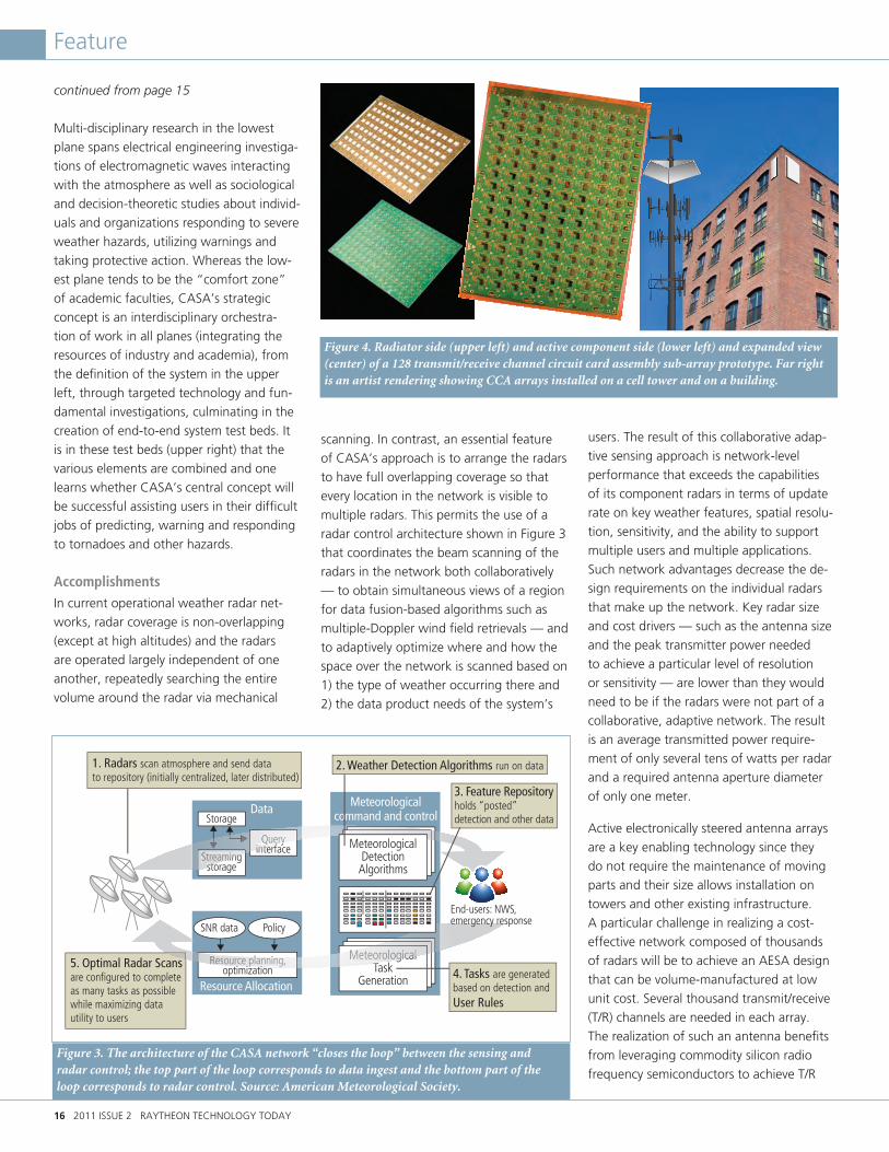
infrastructure. Utilizing Raytheon's radar de-sign and active circuit card assembly (CCA) array technology expertise, a network of low-power, lower-cost sensors will be con-nected in an intelligent network providing distributed collaborative adaptive sensing of atmospheric conditions near the Earth’s sur-face. The closer spacing of these radars will avoid the obstruction caused by the Earth’s curvature and allow forecasters to directly view the lower atmosphere with high-resolution observations. This new dimension to weather observation leads to improved characterization and better forecasting of storms, resulting in improved warning and response to tornadoes and other weather-related hazards.
The central goal is to design and deploy
a system that can sample the atmosphere
when and where the user need is greatest,
and provide accurate, timely and useful
information. It must reliably issue alerts that
the public trusts and responds to appropri-
ately. To accomplish this, the system design
must also address the software and com-
puting architecture required to maintain the
system’s many resources, the data volume,
and the communications and user interface
requirements.
CASA’s Systems ApproachThe solutions to the different problems posed by such an ambitious project are to be found through CASA’s work on three planes of engineering research and develop-ment, as shown in the ERC strategic plan diagram in Figure 2. CASA’s system focus (upper plane) is a real-time distributed sys-tem capable of focusing its resources onto particular volumes of the atmosphere and
delivering forecasts and other data to en-able forecasters, emergency managers and the public to generate accurate alerts and make effective decisions when extreme weather events occur. Realizing an effective and efficient system requires a number of new enabling technologies (middle plane) and fundamental research to create new knowledge (bottom plane).
continued on page 16
CASA
Figure 2. The weather prediction problem is addressed by leveraging the combined skills from industry and academia at three levels of research and development.
System Attributes• Achieve high temporal and spatial resolution mapping throughout troposphere.• Support multiple simultaneous end-users.• Optimize resource allocation for decision support and response to hazardous weather.
Plane 1 System Integration
Plane 2 Technology Research
Plane 3 Fundamental Research
Manysmallradars
Hazard detection/prediction Weather and User
Requirements
System Test Beds
System emulator
Minimum resource nets
Data assimilationVulnerability assessment tool
Electromagneticwave-atmosphere interaction
Cross-layer resource allocation
Small-scale atmosphere
Response tohazards
Small scale detection
User interfacesVery short-range forecast Calibration and
test facilitiesLow-cost radar nodes
Meteorological commandand control
Networked radar waveforms
Policy-steering protocol
Demonstrated Improvements• Sensing • Detecting • Forecasting• Warning• Responding
End-userdecisions
Distributed,adaptive
computationand control
16 2011 ISSUE 2 RAYTHEON TECHNOLOGY TODAY
Feature
continued from page 15
Multi-disciplinary research in the lowest plane spans electrical engineering investiga-tions of electromagnetic waves interacting with the atmosphere as well as sociological and decision-theoretic studies about individ-uals and organizations responding to severe weather hazards, utilizing warnings and taking protective action. Whereas the low-est plane tends to be the “comfort zone” of academic faculties, CASA’s strategic concept is an interdisciplinary orchestra-tion of work in all planes (integrating the resources of industry and academia), from the definition of the system in the upper left, through targeted technology and fun-damental investigations, culminating in the creation of end-to-end system test beds. It is in these test beds (upper right) that the various elements are combined and one learns whether CASA’s central concept will be successful assisting users in their difficult jobs of predicting, warning and responding to tornadoes and other hazards.
AccomplishmentsIn current operational weather radar net-works, radar coverage is non-overlapping (except at high altitudes) and the radars are operated largely independent of one another, repeatedly searching the entire volume around the radar via mechanical
scanning. In contrast, an essential feature of CASA’s approach is to arrange the radars to have full overlapping coverage so that every location in the network is visible to multiple radars. This permits the use of a radar control architecture shown in Figure 3 that coordinates the beam scanning of the radars in the network both collaboratively — to obtain simultaneous views of a region for data fusion-based algorithms such as multiple-Doppler wind field retrievals — and to adaptively optimize where and how the space over the network is scanned based on 1) the type of weather occurring there and 2) the data product needs of the system’s
users. The result of this collaborative adap-tive sensing approach is network-level performance that exceeds the capabilities of its component radars in terms of update rate on key weather features, spatial resolu-tion, sensitivity, and the ability to support multiple users and multiple applications. Such network advantages decrease the de-sign requirements on the individual radars that make up the network. Key radar size and cost drivers — such as the antenna size and the peak transmitter power needed to achieve a particular level of resolution or sensitivity — are lower than they would need to be if the radars were not part of a collaborative, adaptive network. The result is an average transmitted power require-ment of only several tens of watts per radar and a required antenna aperture diameter of only one meter.
Active electronically steered antenna arrays are a key enabling technology since they do not require the maintenance of moving parts and their size allows installation on towers and other existing infrastructure. A particular challenge in realizing a cost-effective network composed of thousands of radars will be to achieve an AESA design that can be volume-manufactured at low unit cost. Several thousand transmit/receive (T/R) channels are needed in each array. The realization of such an antenna benefits from leveraging commodity silicon radio frequency semiconductors to achieve T/R
Figure 3. The architecture of the CASA network “closes the loop” between the sensing and radar control; the top part of the loop corresponds to data ingest and the bottom part of the loop corresponds to radar control. Source: American Meteorological Society.
Figure 4. Radiator side (upper left) and active component side (lower left) and expanded view (center) of a 128 transmit/receive channel circuit card assembly sub-array prototype. Far right is an artist rendering showing CCA arrays installed on a cell tower and on a building.
DataStorage
Queryinterface
Streamingstorage
Resource Allocation
Resource planning,optimization
SNR data Policy
MeteorologicalTask
Generation
Queryyinterf
Q
Streaamingsto
1. Radars scan atmosphere and send datato repository (initially centralized, later distributed)
2. Weather Detection Algorithms run on data
5. Optimal Radar Scans are configured to complete as many tasks as possible while maximizing data utility to users
Meteorologicalcommand and control
Reesource plplanning,i i ti
p MMeteoroologicalT
End-users: NWS,emergency response
MeteorologicalDetectionAlgorithms
3. Feature Repository holds “posted” detection and other data
4. Tasks are generated based on detection and User Rules

David McLaughlin Engineering Fellow, IDS
David McLaughlin is
professor of electri-
cal and computer
engineering and
interim associate
dean of the College
of Engineering
at the University
of Massachusetts at Amherst. He is a
Distinguished Lecturer for the American
Institute of Aeronautics and Astronautics
(AIAA) and was named a Distinguished
Faculty member by the UMass Amherst
Alumni Association.
McLaughlin has held research fellowships at
the U.S. Naval Research Laboratory and the
U.S. Air Force Rome Laboratory. He also
holds an appointment as Engineering Fellow
at Raytheon’s Integrated Defense Systems
business and serves as Director of the NSF
Engineering Research Center for Collaborative
Adaptive Sensing of the Atmosphere (CASA).
CASA is a partnership among academic,
industry and government researchers from
20 different organizations pursuing the fun-
damental knowledge, enabling technologies,
and system level prototypes supporting a
new dense radar network technology that has
the potential to revolutionize how we detect,
track, forecast, warn and respond to hazardous
weather events.
McLaughlin notes that UMass Amherst and
Raytheon have worked together on education
and technological innovation for 30 years. “I’m
a product of that environment, and fortunate
to be in a position where I can work on lots of
new ideas and have access to an almost unlim-
ited range of collaborators and doers at both
organizations. I’m in awe of the team spirit,
work ethic, and incredible depth of expertise
and experience at Raytheon. It amazes me, and
every day I’m glad to be part of it.”
ENGINEERING PROFILE
RAYTHEON TECHNOLOGY TODAY 2011 ISSUE 2 17
CASA
functions, in combination with very low-cost packaging, fabrication and assembly techniques. A prototype CCA AESA, being developed by Raytheon, is shown in Figure 4, along with an artist’s rendering of anten-nas as they might appear mounted on a cellular communications tower and on the side of a building.
CASA’s first test bed was a four-radar system integrated in central Oklahoma, directly in “tornado alley.” Since 2007, this system has tracked dozens of severe thunderstorms moving through the region. Figure 5 illustrates the improved storm mor-phology achieved with the CASA prototype compared with the more limited resolution achieved with the operational NEXRAD radar network deployed across the nation. The test bed demonstrates capabilities that are beyond today’s operational state of the art, including the ability to resolve high-resolution “hook echoes,” which are important indicators of tornado genesis that are poorly resolved in today’s radar network. The life-saving implications of these capabilities were on dramatic display during the May 24, 2011, tornado outbreak
in southwestern Oklahoma. After touch-ing down in McClain County, a tornado progressed on a zigzag path, first traveling east, then north, and then northeast near the town of Newcastle. Since the direc-tional changes happened too quickly to be resolved by the national Doppler radar network, emergency management officials relied on the CASA imagery to follow the twister and move people out of its direct path while they staged rescue and response assets. Officials noted that CASA informa-tion was critical for their decision-making during the event as they worked to shelter 1,200 people. Without the imagery, they would not have known the tornado track was changing direction and they would have directed people to the wrong location.
Motivated by these trials, the CASA team is forming partnerships with weather offices, universities and government agencies in Australia, the U.K., Canada and elsewhere to explore the applicability of the technol-ogy for improved forecasting and response to floods, wind storms, bush fires and other
hazards to life and property. •
David McLaughlin
Figure 5. CASA technology achieves five times better temporal and spatial storm resolution than today’s operational system as shown in this sequence of images from CASA’s “tornado alley” test bed (top row) compared to the operational NEXRAD system (lower row). A funnel cloud, which formed at the tip of the hook-like feature in the imagery, is readily detectable in the CASA imagery. Copyright American Meteorological Society.
18 2011 ISSUE 2 RAYTHEON TECHNOLOGY TODAY
Feature
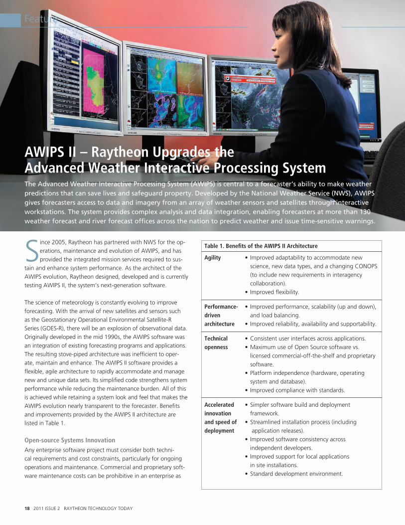
AWIPS II – Raytheon Upgrades the Advanced Weather Interactive Processing System The Advanced Weather Interactive Processing System (AWIPS) is central to a forecaster’s ability to make weather predictions that can save lives and safeguard property. Developed by the National Weather Service (NWS), AWIPS gives forecasters access to data and imagery from an array of weather sensors and satellites through interactive workstations. The system provides complex analysis and data integration, enabling forecasters at more than 130 weather forecast and river forecast offices across the nation to predict weather and issue time-sensitive warnings.
Since 2005, Raytheon has partnered with NWS for the op-erations, maintenance and evolution of AWIPS, and has provided the integrated mission services required to sus-
tain and enhance system performance. As the architect of the AWIPS evolution, Raytheon designed, developed and is currently testing AWIPS II, the system’s next-generation software.
The science of meteorology is constantly evolving to improve forecasting. With the arrival of new satellites and sensors such as the Geostationary Operational Environmental Satellite-R Series (GOES-R), there will be an explosion of observational data. Originally developed in the mid 1990s, the AWIPS software was an integration of existing forecasting programs and applications. The resulting stove-piped architecture was inefficient to oper-ate, maintain and enhance. The AWIPS II software provides a flexible, agile architecture to rapidly accommodate and manage new and unique data sets. Its simplified code strengthens system performance while reducing the maintenance burden. All of this is achieved while retaining a system look and feel that makes the AWIPS evolution nearly transparent to the forecaster. Benefits and improvements provided by the AWIPS II architecture are listed in Table 1.
Open-source Systems InnovationAny enterprise software project must consider both techni-cal requirements and cost constraints, particularly for ongoing operations and maintenance. Commercial and proprietary soft-ware maintenance costs can be prohibitive in an enterprise as
Table 1. Benefits of the AWIPS II Architecture
Agility • Improvedadaptabilitytoaccommodatenew science, new data types, and a changing CONOPS (to include new requirements in interagency collaboration). • Improvedflexibility.
Performance- • Improvedperformance,scalability(upanddown), driven and load balancing. architecture • Improvedreliability,availabilityandsupportability.
Technical •Consistentuserinterfacesacrossapplications. openness •MaximumuseofOpenSourcesoftwarevs. licensed commercial-off-the-shelf and proprietary software. •Platformindependence(hardware,operating system and database). • Improvedcompliancewithstandards.
Accelerated •Simplersoftwarebuildanddeployment innovation framework. and speed of •Streamlinedinstallationprocess(including deployment application releases). • Improvedsoftwareconsistencyacross independent developers. • Improvedsupportforlocalapplications in site installations. •Standarddevelopmentenvironment.
RAYTHEON TECHNOLOGY TODAY 2011 ISSUE 2 19
Feature
large as the NWS. To address these issues, Raytheon created an innovative next-gener-ation design for AWIPS II using open-source software. Under this initiative, Raytheon is migrating legacy AWIPS functionality to a service-oriented architecture that supports modern, standards-based interfaces.
The team focused on four of the “-ilities” to drive the new AWIPS II architecture:
• Scalability: Horizontal scalability allows the scaling of system size and perfor-mance by adding low-cost commodity hardware for cost-effective support of new satellite and sensor systems. The framework can scale down to small lap-tops, and through workstations (Figure 1), to clusters of enterprise servers without a software change.
• Flexibility: Standards-based interfaces make AWIPS II highly portable and easy to integrate with, providing end users with greater flexibility for developing and integrating new tools and capabilities to the AWIPS platform.
• Extensibility: The modernized archi-tecture allows for simplified integration of new data sets and environmental ap-plications without having to make major changes to the system infrastructure.
• Maintainability: The use of modular de-sign and loose coupling of components, along with consistent use of standards and modern development tools, results in reduced complexity and simplified main-tenance. This also aids in maintaining overall software quality.
Raytheon’s AWIPS II solution reduces main-tenance requirements, improves reliability and enhances forecasting performance. Common services and open-source software allow the NWS to be more responsive to the requirements for new weather products and services. It also gives users outside the weather community the ability to more easily ingest, process and visualize essential environmental data to support critical mission needs.
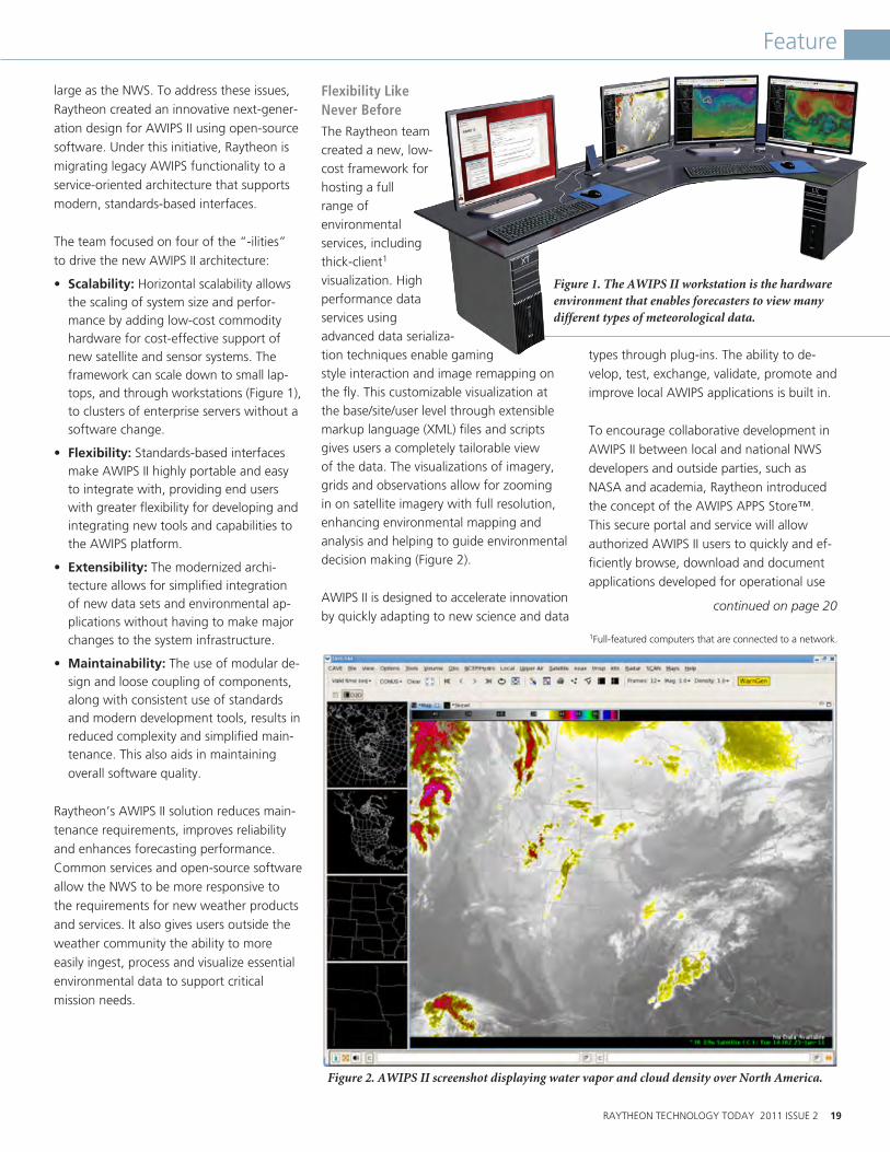
Flexibility LikeNever BeforeThe Raytheon teamcreated a new, low-cost framework for hosting a full range of environmental services, including thick-client1 visualization. High performance data services using advanced data serializa-tion techniques enable gaming style interaction and image remapping on the fly. This customizable visualization at the base/site/user level through extensible markup language (XML) files and scripts gives users a completely tailorable view of the data. The visualizations of imagery, grids and observations allow for zooming in on satellite imagery with full resolution, enhancing environmental mapping and analysis and helping to guide environmental decision making (Figure 2).
AWIPS II is designed to accelerate innovation by quickly adapting to new science and data
types through plug-ins. The ability to de-velop, test, exchange, validate, promote and improve local AWIPS applications is built in.
To encourage collaborative development in AWIPS II between local and national NWS developers and outside parties, such as NASA and academia, Raytheon introduced the concept of the AWIPS APPS Store™. This secure portal and service will allow authorized AWIPS II users to quickly and ef-ficiently browse, download and document applications developed for operational use
continued on page 20
Figure 1. The AWIPS II workstation is the hardware environment that enables forecasters to view many different types of meteorological data.
Figure 2. AWIPS II screenshot displaying water vapor and cloud density over North America.
1Full-featured computers that are connected to a network.

BackgroundThe Joint Environmental Toolkit (JET) Increment 1 solution is an integrated U.S. Air Force weather system, which is scalable and meets U.S. gov-ernment needs for weather forecast and effects generation, meteorological watch, and observa-tion management with increased accuracy and decreased latency. The system provides mission-tailored information, products and services to the U.S. Air Force and U.S. Army. Most JET capability is available to users via a standard Web browser and is currently deployed to 187 USAF and Army installations around the world, supporting the warfighter and theater operations.
Raytheon Completes Joint Environmental Toolkit Upgrades for Air Force Weather
20 2011 ISSUE 2 RAYTHEON TECHNOLOGY TODAY
Feature AWIPS
continued from page 19
and published through the NWS. The AWIPS APPS Store will enable knowledge sharing across the forecaster user community, linking operations and research across the new enterprise infrastructure to enhance all levels of weather forecasting operations.
AWIPS II leverages the open service-oriented architecture and interoperable environment to anticipate and accommodate new and advanced applications. New data types, visualization and decision support tools, and scientific algorithms can all be incorporated through the features already in the AWIPS II archi-tecture. It facilitates installation, collaboration, publication and notification, promoting a vibrant life cycle of new and improv-ing applications across the NWS enterprise.
When this community of contributors has the tools to develop applications within the AWIPS II architecture, their work will transition into operations more quickly and easily at much lower costs. Faster and more accurate warnings and forecasts will result from this rapid infusion of new science and applica-tions into the AWIPS II framework.
Next-Generation ForecastingReaching beyond the weather services and river forecast offices, Raytheon is bringing AWIPS II baseline code into the operations for NWS’ nine National Centers for Environmental Prediction, providing a seamless weather enterprise that integrates all lev-els of NWS operations.
The foundation of AWIPS II supports the future evolution for decision support services as NWS brings in other data sources and information into its systems. This provides a common operating picture to better support the customer for emergency response, aviation and more. For instance, by employing AWIPS II decision-support tools, emergency managers can improve incident management through better forecasting of the weather that impacts their operations and the lives and safety of those they serve.
AWIPS II does not change how forecasters currently do their jobs. It all happens behind the scenes. The biggest differences forecasters notice are enhanced displays and performance due to sharing of data between applications. AWIPS II pro-vides next-generation decision support for the NWS through improved data delivery, collaboration, information generation and visualization. Raytheon’s open, scalable, standards-based, service-oriented architecture provides a flexible and expandable system that meets the long-term requirements necessary for
predicting weather now and in the future. • Andy Nappi

RAYTHEON TECHNOLOGY TODAY 2011 ISSUE 2 21
Feature
The full JET capability was originally deployed to all installations due to network bandwidth limitations preventing the use of a remote server. As bandwidth improved and the concept of operations evolved, the customer and Raytheon recognized the opportunity to reduce system administration and fielding costs by only deploying the full capability at regional centers and by providing “reach-back” to remaining users via a Web browser. These changes involve re-moving the current full JET instance at the deployed locations and replacing it with a sensor collection appliance. This SCA provides local base observations and basic weather support to local air traf-fic control (ATC) facilities. In addition to the concept of operations changes, Raytheon improved the forecasting and analysis capabili-ties to increase flight safety and mitigate environmental impacts on operations.
JET DemonstrationsRaytheon has conducted demonstrations for operational users illus-trating improved weather impacts and forecasting capabilities. As a result of the demonstrations, we have created anticipation concern-ing the evolution of warfighter support capabilities and its positive impact on operations. Figure 1 depicts the real-time assessment of weather impacts on flight operations. The figure shows a mis-sion route with landing and takeoff locations in Florida, Louisiana, Maryland and Alabama. Each landing and takeoff location, indi-cated by the circle with three pie sections (site impact icons) can display the local observations and weather watches, warnings and advisories. With the addition of the radar layer, a forecaster can clearly see a high potential for impacts along the mission route. Another layer that is displayed is the PIREP data (pilot reports from aircraft flying at that location). The forecaster can select the white airplane symbol to view altitude, winds, icing, turbulence and tem-perature data, as well as the time of the report.
Key Capabilities
• Mission management. This capability provides a workflow for forecasters to generate weather briefings on planned missions for the responsible aircrew. These briefings include relevant en-vironmental data, imagery and impact assessments. JET provides interoperability with command and control systems for creating missions based on air task orders, air control orders and common route definitions.
• Integrated geospatial display (IGD). This new capability le-verages geographic information system technology and Open Geospatial Consortium services to allow users to visualize the environmental data processed by JET, fused with mission data in a geospatial context. This provides a nearly instantaneous understanding of situational awareness and potential impacts on operations. Figure 1 depicts the IGD with a planned mission route overlaid with radar data. The color icons at each point in the route indicate the environmental impact assessment for that point based on the current observation, forecast, and any weather watches, warnings or advisories.
• SCA ATC support. The ATC user interface provides airfield sensor readouts and basic local weather information for support of local air operations. This capability replaces existing displays and conforms to critical ATC display requirements.
Raytheon’s solution to Air Force Weather’s evolving concept of op-erations and requirements provides a highly available and scalable system. The modifications being made to the JET system improve the forecaster’s ability to predict weather events and the impact of those events on mission planning, resulting in increased safety to the warfighter and reduced cost to the Air Force and Army. •
Tim Ratliff, Dan Weeks
Figure 1. The new JET integrated geospatial display provides a comprehensive real-time assessment of weather impact on flight operations.

22 2011 ISSUE 2 RAYTHEON TECHNOLOGY TODAY
Feature
Raytheon Delivers NextGen Weather Demonstrations to the FAA
The goal of the Federal Aviation Administration’s (FAA) Next-Generation (NextGen) Air Transportation System is
to address the needs of the aviation industry for increased capacity, safety and efficiency. This includes the demand for air traffic ser-vices to provide accurate and timely weather information at the temporal and spatial scales required by aviation decision mak-ers. Since weather accounts for 70 percent of air traffic delays in the U.S., improving information about weather and weather impact is vital to meeting future demands for air travel. Similar challenges related to weather affect flights across the globe. As a world leader in air traffic control systems, Raytheon is focused on developing and de-livering air traffic systems and products that significantly improve the efficiencies of the global aviation fleets. Doing so will signifi-cantly reduce the amount of fuel utilized by large aircraft, which also reduces the fleets’ carbon dioxide emissions.
Figure 1 shows some of the elements of the air traffic control and weather data systems that will be integrated by NextGen to im-prove data collection, data fusion, conversion to knowledge and knowledge dissemination.
Raytheon’s NextGen Weather Demonstrations In support of the FAA’s goal, Raytheon con-ducted demonstrations that illustrate how improved weather and weather impact infor-mation will be conveyed to decision makers, including air traffic controllers and pilots. The data and information will ultimately be conveyed to systems connected via the FAA’s System Wide Information Management (SWIM) system, enabling trajectory-based operations1. These demonstrations illustrate the visualization and decision support tools that will enable NextGen weather knowl-edge collection and dissemination.
Raytheon leveraged existing technologies from across the company for the foundation of the end-to-end demonstration. These include:
• Universal Framework (uFrame™) is a data-agnostic services framework capable
of ingesting, fusing and displaying a wide array of environmental data.
• Standard Terminal Automation Replacement System (STARS) is a replacement for the Automated Radar Terminal System. STARS receives radar data and flight plan information and pres-ents it to air traffic controllers on high-resolution, 20 by 20-inch color displays, allowing the controller to monitor, control and accept handoff of air traffic.
• Electronic Data Manager (EDM) is a light, portable touchscreen computer in the form of a kneeboard that provides the aviator with a global positioning system moving-map capability, the ability to read in sunlight, and Microsoft Windows® soft-ware to replace the current kneeboard. The EDM displays moving maps with aircraft position and waypoints — along with checklists, manuals and approach plates — in PDF format. It imports mission planning data, providing capability for cal-culations of weight, balance and aircraft performance.
• Battle Command System is the primary air defense/battle management system for North American Air Defense and the U.S. Pacific Command. The interoperable, open-architecture air defense and com-mand and control platform supports the U.S. and Canadian homeland defense and drug interdiction missions.
Raytheon partnered with AirDat LLC to in-tegrate data collected with its Tropospheric Airborne Meteorological Data Report (TAMDAR) weather sensors and advanced atmospheric modeling capabilities. The infor-mation was translated through Raytheon’s uFrame system and conveyed to STARS to provide environmental impact areas for route planners in terminal radar approach control facilities. Similarly, the information could also be conveyed to Raytheon’s state-of-the-art air traffic management system, AutoTrac III2. The environmental data and impact in-formation, including reports and alerts, was conveyed to the cockpit via the EDM. Figure 2 depicts this prototype end-to-end solution.
The TAMDAR sensors were deployed on more than 300 commercial regional jet air-craft to allow collection of higher resolution atmospheric information. This information was transmitted via Inmarsat communica-tions links to the AirDat facility, where it was used to seed an advance atmospheric gridded forecast model. Environmental im-pacts to aviation were calculated within the uFrame system, following the ingestion and registration of disparate data types, includ-ing the AirDat gridded forecast model. These impacts to aviation were provided to STARS as AVOI3 regions and indicated on the STARS air traffic control display. Environmental impact areas, along with satellite and radar imagery, were provided to EDM as geo-graphic image files. In addition, extensible
Figure 1. FAA NextGen Data Fusion Challenge. NextGen must convert data to deliver appropriate and timely knowledge to decision makers at all levels.

Visualization AVOI Cap Alert
STARS ATC DisplayModeling & Analysis
SensingCockpit Display
RAYTHEON TECHNOLOGY TODAY 2011 ISSUE 2 23
Feature
markup language (XML) structures and Open Geospatial Consortium-compliant services were stood up to convey aviation impact area knowledge to other systems. Examples of the rendering of these impact areas are shown in Figure 3.
The programs that will benefit from these demonstrations and the development they represent include the NextGen Weather Processor and NextGen Network Enabled Weather program under the direction of the FAA, and the 4-D Weather Data Cube under the direction of the National Oceanic and Atmospheric Administration (NOAA), with close alignment to the needs and require-ments of the FAA. Raytheon’s approach and
the underlying technologies being developed will support the needs of these programs and will help the FAA and NOAA achieve their goals.
By equipping fleets internationally, AirDat data and resultant modeling, coupled with Raytheon’s automation systems, can be used to more accurately forecast weather events that impact flight planning, resulting in increased efficiency and reduced delays. Furthermore, this information can provide real-time weather information in regions of the world where the data and forecasts are
currently sparse or don’t exist. •
Paul Ackroyd, Bob Bowne
Figure 3. Aviation impact areas. The left image is rendered in NASA World Wind4 via XML structure. The right image is rendered via Open Geographic Consortium Services in the Thales Raytheon battle control system.
Figure 2. Raytheon’s NextGen Solution provides environmental impact knowledge to all tiers of the FAA organization.
1The concept of an air traffic management system in which every aircraft that is operating in or managed by the system is represented by a four-dimensional trajectory providing separation, sequencing, merging and spacing of flights based on a combination of their current and future positions. It operates gate-to-gate, extending benefits to all phases of flight operations. 2AutoTrac III features a new generation of flight and surveillance data processing systems to ensure the safety of air traffic. The system’s modern, open architecture design and high performance is fully adaptable and scalable to fit any air traffic management environment, from simple tower automation to a fully integrated multi-center system.3The means by which an airspace volume is designated and shared among systems. AVOIs (airspace volume of interest) may represent regions such as temporary flight restriction or special-use airspace areas. 4An open source virtual globe developed by NASA and the open source community for use on personal computers.
Bob Bowne Senior Principal Software Engineer, IIS
In his 15 years with
Raytheon, Bob
Bowne has been a
developer on sev-
eral environmental
systems, including
the Satellite Data
Handling System
Upgrade and the Joint Environmental Toolkit.
He also conducted ground demonstrations
during the proposal phase, which led to the
NPOESS/JPSS program award.
As the Environmental Chief Engineer for IIS,
Bowne oversees the development and inte-
gration of weather data processing systems.
His concentration is in the development of
software algorithms to determine mission,
platform, sensor and weapon impacts due to
environmental or climatological phenomenon.
Presently, Bowne leads Raytheon’s uFrame™
(universal framework), Raytheon’s Arctic
Monitoring and Prediction (RAMP), and
Raytheon’s Environmental Monitoring and
Prediction (REMAP) developments. Resulting
capabilities have been integrated with com-
mand and control systems and have been
demonstrated to U.S. Department of Defense
and Canadian Ministry of Defense customers
as a means to fill current operational gaps.
Bowne gives credit to his military career for
giving him insight into the user’s perspective
and the role that environmental situational
awareness plays in mission planning and
execution. Also, a close customer relationship
fostered through frequent briefings and tech-
nical interchange meetings has helped him to
focus on particular customer needs.
Bowne offers the following advice to up-and-
coming engineers: “Learn how and when
to take risks. Risk is an unavoidable part of
engineering. Engineers must know how to
understand and manage risk and its impact.”
ENGINEERING PROFILE
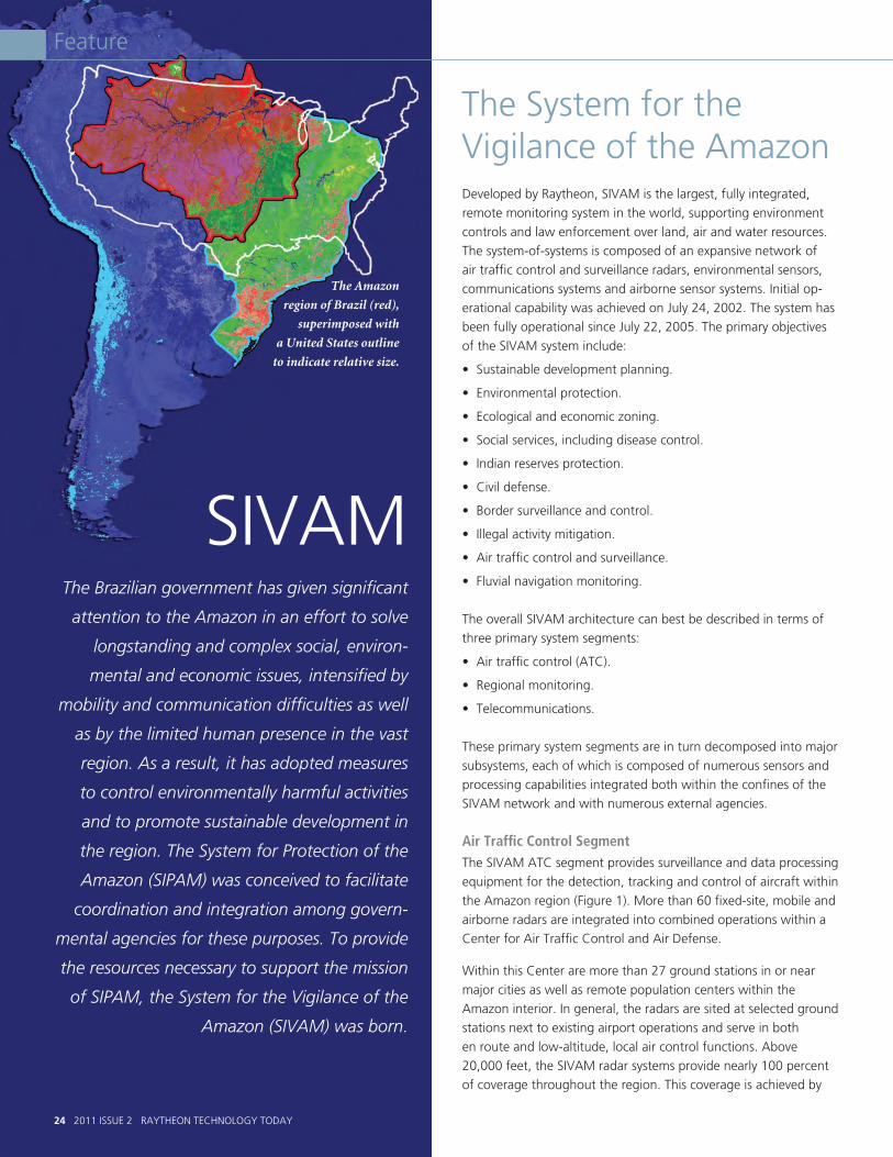
24 2011 ISSUE 2 RAYTHEON TECHNOLOGY TODAY
Feature
The System for the Vigilance of the AmazonDeveloped by Raytheon, SIVAM is the largest, fully integrated, remote monitoring system in the world, supporting environment controls and law enforcement over land, air and water resources. The system-of-systems is composed of an expansive network of air traffic control and surveillance radars, environmental sensors, communications systems and airborne sensor systems. Initial op-erational capability was achieved on July 24, 2002. The system has been fully operational since July 22, 2005. The primary objectives of the SIVAM system include:
• Sustainabledevelopmentplanning.
• Environmentalprotection.
• Ecologicalandeconomiczoning.
• Socialservices,includingdiseasecontrol.
• Indianreservesprotection.
• Civildefense.
• Bordersurveillanceandcontrol.
• Illegalactivitymitigation.
• Airtrafficcontrolandsurveillance.
• Fluvialnavigationmonitoring.
The overall SIVAM architecture can best be described in terms of three primary system segments:
• Airtrafficcontrol(ATC).
• Regionalmonitoring.
• Telecommunications.
These primary system segments are in turn decomposed into major subsystems, each of which is composed of numerous sensors and processing capabilities integrated both within the confines of the SIVAM network and with numerous external agencies.
Air Traffic Control SegmentThe SIVAM ATC segment provides surveillance and data processing equipment for the detection, tracking and control of aircraft within the Amazon region (Figure 1). More than 60 fixed-site, mobile and airborne radars are integrated into combined operations within a Center for Air Traffic Control and Air Defense.
Within this Center are more than 27 ground stations in or near major cities as well as remote population centers within the Amazon interior. In general, the radars are sited at selected ground stations next to existing airport operations and serve in both en route and low-altitude, local air control functions. Above 20,000 feet, the SIVAM radar systems provide nearly 100 percent of coverage throughout the region. This coverage is achieved by
The Brazilian government has given significant
attention to the Amazon in an effort to solve
longstanding and complex social, environ-
mental and economic issues, intensified by
mobility and communication difficulties as well
as by the limited human presence in the vast
region. As a result, it has adopted measures
to control environmentally harmful activities
and to promote sustainable development in
the region. The System for Protection of the
Amazon (SIPAM) was conceived to facilitate
coordination and integration among govern-
mental agencies for these purposes. To provide
the resources necessary to support the mission
of SIPAM, the System for the Vigilance of the
Amazon (SIVAM) was born.
SIVAM
The Amazon
region of Brazil (red),
superimposed with
a United States outline
to indicate relative size.
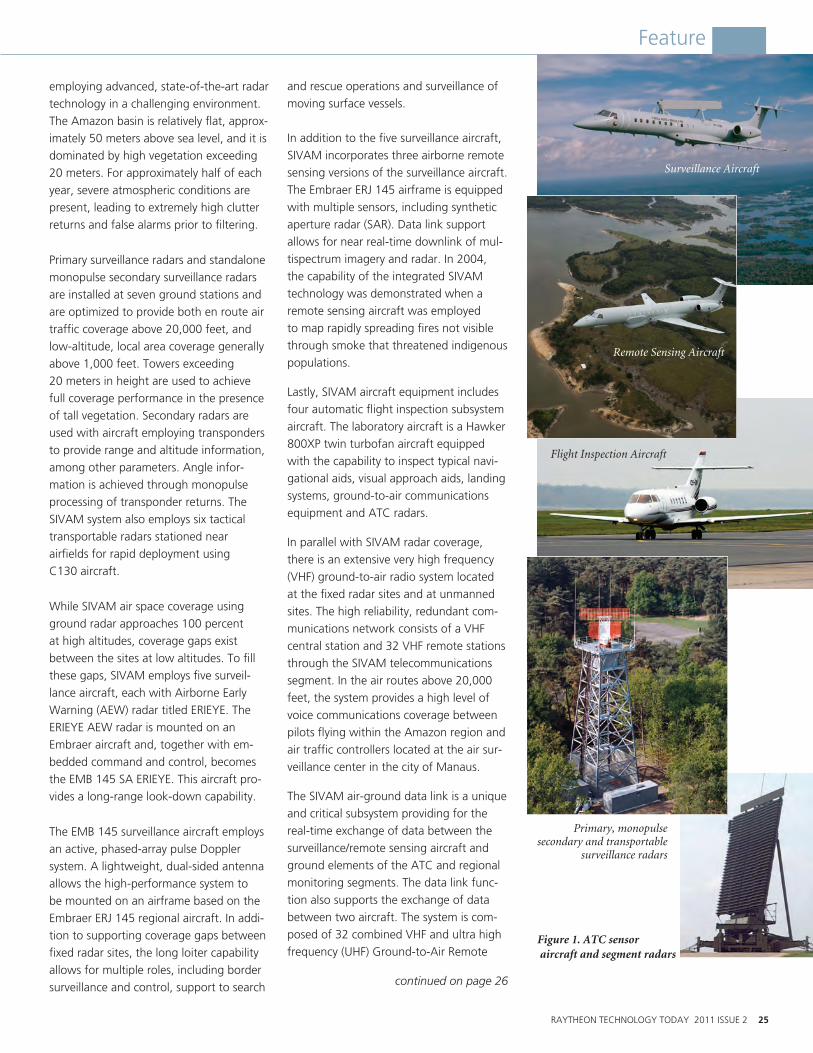
RAYTHEON TECHNOLOGY TODAY 2011 ISSUE 2 25
Feature
employing advanced, state-of-the-art radar technology in a challenging environment. The Amazon basin is relatively flat, approx-imately 50 meters above sea level, and it is dominated by high vegetation exceeding 20 meters. For approximately half of each year, severe atmospheric conditions are present, leading to extremely high clutter returns and false alarms prior to filtering.
Primary surveillance radars and standalone monopulse secondary surveillance radars are installed at seven ground stations and are optimized to provide both en route air traffic coverage above 20,000 feet, and low-altitude, local area coverage generally above 1,000 feet. Towers exceeding 20 meters in height are used to achieve full coverage performance in the presence of tall vegetation. Secondary radars are used with aircraft employing transponders to provide range and altitude information, among other parameters. Angle infor-mation is achieved through monopulse processing of transponder returns. The SIVAM system also employs six tactical transportable radars stationed near airfields for rapid deployment using C130 aircraft.
While SIVAM air space coverage using ground radar approaches 100 percent at high altitudes, coverage gaps exist between the sites at low altitudes. To fill these gaps, SIVAM employs five surveil-lance aircraft, each with Airborne Early Warning (AEW) radar titled ERIEYE. The ERIEYE AEW radar is mounted on an Embraer aircraft and, together with em-bedded command and control, becomes the EMB 145 SA ERIEYE. This aircraft pro-vides a long-range look-down capability.
The EMB 145 surveillance aircraft employs an active, phased-array pulse Doppler system. A lightweight, dual-sided antenna allows the high-performance system to be mounted on an airframe based on the Embraer ERJ 145 regional aircraft. In addi-tion to supporting coverage gaps between fixed radar sites, the long loiter capability allows for multiple roles, including border surveillance and control, support to search
and rescue operations and surveillance of moving surface vessels.
In addition to the five surveillance aircraft, SIVAM incorporates three airborne remote sensing versions of the surveillance aircraft. The Embraer ERJ 145 airframe is equipped with multiple sensors, including synthetic aperture radar (SAR). Data link support allows for near real-time downlink of mul-tispectrum imagery and radar. In 2004, the capability of the integrated SIVAM technology was demonstrated when a remote sensing aircraft was employed to map rapidly spreading fires not visible through smoke that threatened indigenous populations.
Lastly, SIVAM aircraft equipment includes four automatic flight inspection subsystem aircraft. The laboratory aircraft is a Hawker 800XP twin turbofan aircraft equipped with the capability to inspect typical navi-gational aids, visual approach aids, landing systems, ground-to-air communications equipment and ATC radars.
In parallel with SIVAM radar coverage, there is an extensive very high frequency (VHF) ground-to-air radio system located at the fixed radar sites and at unmanned sites. The high reliability, redundant com-munications network consists of a VHF central station and 32 VHF remote stations through the SIVAM telecommunications segment. In the air routes above 20,000 feet, the system provides a high level of voice communications coverage between pilots flying within the Amazon region and air traffic controllers located at the air sur-veillance center in the city of Manaus.
The SIVAM air-ground data link is a unique and critical subsystem providing for the real-time exchange of data between the surveillance/remote sensing aircraft and ground elements of the ATC and regional monitoring segments. The data link func-tion also supports the exchange of data between two aircraft. The system is com-posed of 32 combined VHF and ultra high frequency (UHF) Ground-to-Air Remote
continued on page 26
Surveillance Aircraft
Remote Sensing Aircraft
Flight Inspection Aircraft
Primary, monopulse secondary and transportable
surveillance radars
Figure 1. ATC sensor aircraft and segment radars

26 2011 ISSUE 2 RAYTHEON TECHNOLOGY TODAY
Feature
continued from page 25
Stations — co-located with the VHF ATC sites — and the air-ground data link inter-face controller (AGDLIC) located in the air surveillance center.
The AGDLIC handles up to 80 data link
connections with the VHF/UHF radio sites
and multiple aircraft in operation. Once
established, message traffic between that
aircraft and any destination within the ATC
and regional monitoring segments can be
routed transparently by the AGDLIC based
on message type or aircraft location, or as
addressed by the aircraft itself. In the ab-
sence of VHF/UHF coverage to an aircraft, a
data link can be maintained with an aircraft
using alternate high frequency radio cover-
age, effectively providing 100 percent data
link coverage of the Amazon.
Regional Monitoring Segment
The SIVAM regional monitoring segment
provides sensor data and processing ca-
pabilities for environmental monitoring.
It includes environmental data collection
platform sensors; altitude weather stations;
surface weather stations; TIROS (television
infrared observation satellite), GOES
(geostationary operational environment
satellite), the Brazilian SCD-1 (satélite de
coleta de dados) and RDSS (radio determi-
nation satellite system) ground stations; and
an extensive lightning detection network.
Environment data is collected continuously
and used to build and update detailed
knowledge of the Amazon region.
Classification and monitoring functions
include deforestation, forest fires, soil, crop
and agricultural land usage, forest cover
and changes, flooding, water pollution, air
pollution and greenhouse gases, regional
flora and fauna habitats and human inter-
vention in the environment.
Processing is performed at four coordination
subcenters in the cities of Manaus, Porto
Velho, Belém and Brasilia. These are the
data repositories, processing nodes, and the
product and service providers for SIVAM.
They are interlinked by high-bandwidth
data and voice communications, and they
provide system access to local and remote
users. They include specialized computers,
software and a network of integrated data-
bases that support data preprocessing and
detailed analysis of collected sensor data.
They provide capabilities for the retrieval,
integration, presentation and analysis of
information. In addition to SIVAM sensor
data, they provide the means to access
and maintain extensive data sets, including
historical data, library data, map data and
other pieces of reference information critical
to the user community.
Meteorological, hydrological, and both
ground- and satellite-based environmental
data are transmitted to the coordination
ManausCoordination
Subcenter
Porto VelhoCoordination
Subcenter
BelémCoordination
Subcenter
BrasiliaGeneral
CoordinationCenter
REGIONAL SUBCENTER CONNECTIVITYCOMMUNICATIONS SUBNETWORK
SURVEILLANCE CONNECTIVITYCOMMUNICATIONS SUBNETWORK
n
SatelliteData
SatelliteComms
Remote Users>1,000
Sub
t U
BroadcastComms
Surveillanceand RemoteSensing
RemoteSensors
Radars
VHF/UHFRadio
Data Link
Remote Ground Stations (27+)
Air-GroundData Link Controller
VHF/UHFRadio
Central Station
Air TrafficControlCenter
ManausAir Surveillance Center
Figure 2. The SIVAM telecommunications and support segment provides reliable high speed connectivity for command and control and for data distribution to a broad range of users.

RAYTHEON TECHNOLOGY TODAY 2011 ISSUE 2 27
SIVAM
subcenters for processing, cataloging,
analysis and visualization. The subcenters
exchange information to combine and
share data with other regions. Each sub-
center provides powerful data relationship
tools, allowing different types of sensor
data and imagery to be analyzed in user-
defined combinations. The unique analysis
products which result from these tools
provide insight into the evolving character-
istics of the environment and the human
activity within it, facilitate the correlation
of information, and provide decision aids
for operational planning, coordination
and monitoring.
The regional monitoring segment is
supported by the remote sensing aircraft
system. This system and its associated
equipment suite provides synthetic ap-
erture radar, multispectral, infrared and
visible light imagery via the air-ground
data link and magnetic tapes. Additional
imagery data is obtained from real-time
satellite passes such as GOES and TIROS.
Weather data from pulse-Doppler weather
radars located throughout the region is
transmitted to the regional monitoring
segment in real time.
Telecommunications SegmentIn addition to direct support to operations
and the scientific community, hundreds
of remote users have access to the
SIVAM database information and services
through the telecommunications segment.
A system of very small aperture terminals
provides secure satellite communications
to many remote cities where land-based
telecommunications are not available. The
remote users have computer, telephone,
and fax connectivity with the system.
Examples of the use of the user network
are the dissemination of health and safety
alerts, weather alerts and the coordination
of regional activities.
The SIVAM telecommunications seg-
ment is composed of a highly reliable,
redundant network of communications
equipment using government and com-
mercial services to provide secure voice
and data connectivity between SIVAM
sites. The communications architecture
is made up of two major subnetworks:
one provides connectivity between the
air surveillance center and more than 27
associated second-tier surveillance and
telecommunications installations, and the
other provides high-speed, multiredun-
dant connectivity between the regional
subcenters and the general coordination
center (Figure 2). Primary connectivity
uses government satellite services, while
secondary connectivity is supported by
the commercial telecommunications infra-
structure and regional service providers.
Conclusion
This high-level description of the three
major segments of the SIVAM architecture
— air traffic control, remote monitor-
ing, and telecommunications — provides
an overview of the SIVAM system-of-
systems. Since 2005, SIVAM has been
fully operational. Remote sensor data and
measurements are collected, integrated
and processed to support environmental
monitoring and protection of over
1.5 million square miles of land, air and
water resources that encompass the
Amazon region. •
Paul Ferraro
AcknowledgmentPartners in the development of SIVAM are Raytheon Company, the Brazilian Integrating Company ATECH, and Embraer S.A., working under the direction of the Coordinating Commission of the Project for the Amazon Surveillance System (CCSIVAM) and the Brazilian Air Force, Força Aérea Brasileira.
Paul Ferraro Vice President Engineering and Technology, NCS
Paul Ferraro is the
newly appointed
vice president of
Engineering and
Technology for
Network Centric
Systems. Ferraro comes to NCS from Integrated
Defense Systems where he was director of
Engineering’s Electrical Design Directorate,
responsible for all phases of the electrical design
cycle, including design, development, test, man-
ufacture and support across all programs.
Ferraro is enthusiastic about the application of
technology to develop innovative solutions. He
works with some of the world’s best and bright-
est technologists and engineers to help create
solutions to complex and challenging problems.
From 1997 through 2002, Ferraro was the
deputy program manager and technical director
responsible for all continental U.S. operations
for the System for the Vigilance of the Amazon
(SIVAM). Fully operational since July 2002,
this landmark $1.4 billion program provides
the Brazilian government with environmental
and air traffic monitoring essential to
preserving this nearly 5.2 million square
kilometers of rainforest.
Products and services provided by Ferraro’s
organization are core to many of Raytheon’s
technical solutions and integral to some of
the world’s most complex and sophisticated
systems.
“What we do is important,” Ferraro comments.
“Our products save lives. To be able
to contribute to providing mission critical
solutions to seemingly impossible problems
that have a positive impact on our customers
and our environment is both exciting and
an honor.”
ENGINEERING PROFILE

28 2011 ISSUE 2 RAYTHEON TECHNOLOGY TODAY
Feature
The oceans cover approximately 72 percent of the Earth’s surface. They are where the planet stores vast
amounts of heat and a significant amount of carbon dioxide. Increasingly, natural re-sources such as oil and minerals are being found throughout our oceans. The oceans drive our weather and are related to key climate processes. Yet we know little about the complex ocean ecosystem that so pro-foundly affects life on the planet. Figure 1 provides a perspective of the multiple interactive processes that influence the ocean environment.
Given the vastness of the oceans and the need for a greater understanding of ocean processes, oceanographers in the United States have recently begun a large-scale engineering program, a system-of-systems, called the Ocean Observatories Initiative (OOI). The OOI program, funded by the National Science Foundation, is planned as a networked infrastructure of sensor systems that will address vital science questions by measuring physical, chemical, geological and biological variables of the ocean. The OOI will provide research sci-entists, educators, students and the public
with unparalleled access to the physical, chemical, geological and biological phe-nomena of the ocean. Raytheon engineers have been working closely with a number of organizations involved in the program.
The OOI’s focuses on the following scientific themes:
• Ocean-atmosphereexchange.
• Climatevariability,oceancirculation and ecosystems.
• Turbulentmixingandbiophysical interactions.
A Collaborative Effort in a System-of-Systems:
The Ocean Observatories Initiative

RAYTHEON TECHNOLOGY TODAY 2011 ISSUE 2 29
Feature
• Coastaloceandynamicsandecosystems.
• Fluid-rockinteractionsandthe sub-seafloor biosphere.
• Plate-scaleoceangeodynamics.
Creating PartnershipsGaining insight in these scientific focus areas will allow the OOI program to address a set of broader environmental concerns, including the need for an increased under-standing of coastal ocean ecosystem health, climate change, carbon cycling, and ocean acidification. For example, the OOI may provide insight into the “ocean conveyor” (Figure 2). The ocean conveyor is of keen
interest to scientists because these circulat-ing ocean currents move heat throughout the planet and weather patterns may be af-fected if shifts occur in the conveyor.
The expertise needed to construct and manage the OOI will come from a variety of entities in the public and private sectors. The OOI program is managed and coordinated by the OOI Project Office at the Consortium for Ocean Leadership (COL) in Washington, D.C. The Consortium is responsible for construction and initial operation of the OOI network.
Four implementing organizations are responsible for construction and develop-ment of the overall program. Woods Hole Oceanographic Institution (WHOI) with its partners — Oregon State University and Scripps Institution of Oceanography — is responsible for the coastal and global
arrays and their autonomous vehicles. The University of Washington is responsible for regional cabled seafloor systems and moor-ings. The University of California, San Diego (UCSD), implements the cyberinfrastructure component. Rutgers, the State University of New Jersey, is responsible for the edu-cation and public engagement software infrastructure.
Raytheon provides specific engineering services and process rigor to COL and to three of the implementing organizations (WHOI, UCSD, and Rutgers). In varying degrees, Raytheon provides systems en-gineering, systems architecture, design engineering, technical management and planning, schedule assistance, and risk and opportunity management.
continued on page 30
< Figure 1. The ocean is a highly complex ecosystem. The OOI is designed with that complexity in mind. Key science themes drive which data will be collected to better under-stand this dynamic four-dimensional environ-ment. Biological, chemical, geological and physical processes and components will be ex-amined. Graphic courtesy of the OOI Regional Scale Nodes and Center for Environmental Visualization, University of Washington.
^ Figure 2. The OOI is designed to provide additional scientific focus on areas such as ocean circulation, carbon cycling, ocean acidification and coastal ocean ecosystem health. This figure indicates key areas where ocean-related heat is believed to be exchanged with the atmosphere.
Heat release to
atmosphere
Heat release to
atmosphere
Heat release to
atmosphere
Heat release to
atmosphere
Coldsalinedeep current
Great Ocean Conveyor Belt
Warm surfacecurrent

30 2011 ISSUE 2 RAYTHEON TECHNOLOGY TODAY
Feature
Developing a System-of-SystemsThe OOI is global in scale. Various team members are involved with the construction of the infrastructure, which includes arrays of buoys, moorings, profilers and autono-mous vehicles. Measurements and data delivery are enabled by a variety of sensors and related cyberinfrastructure. The
system will be capable of collecting many different classes of measurements using ap-proximately 800 instruments of 49 different types deployed on a variety of platforms, some of which are shown in Figure 3.
It is important to note that mobile platforms, such as profilers, gliders and autonomous underwater vehicles, will be used and that the cyberinfastructure will be able to task some of these mobile assets to enable adaptive sampling. Sensors range from traditional instruments that collect information on pH, dissolved oxygen and temperature, to hydrophones, digital cam-eras and bioacoustic equipment.
As shown in Figure 4, the system will have infrastructure at multiple key geographic locations:
• Fourglobalscalearraysathighlatitudes.
• Threeregionalscalenodesinoneareaoffthe North American Pacific coast.
• Twocoastalscalearrays,oneoneachNorth American coast.
Figure 5 is an illustration of how one of the arrays, the Pioneer Array, will operate. The Pioneer Array will be relocatable should scientists wish to gather data at a different geographic site. It will initially be located off the U.S. Atlantic coast along the continental shelf break.
These array elements will be connected via a cyberinfrastructure, enabling command and control, adaptive sampling, data distribu-tion, collaborative analysis, and a variety of interfaces for users. UCSD is building the cyberinfrastructure component of the OOI program with Raytheon’s support.
It is important to note that the OOI will collect data along a continuum of time
Figure 3. Some technologies to be used in the OOI system-of-systems: (clockwise from far left) recover-able bottom frames with mooring anchor and instrumentation, autonomous gliders, buoys with two-way telemetry, autonomous underwater vehicles and seafloor cable laying equipment. Images from oceanobservatories.org.
Courtesy Teledyne Webb Research
Courtesy Hydroid, Inc.
Photo by Craig Risien, Oregon State University
Photo by Paul Hagstrom/Cecile Durand, OOI program
continued from page 29
Figure 4. The OOI will include arrays at global sites in high latitudes (circled), the regional scale nodes cabled network off the coast of the state of Oregon, and moveable arrays of sensors off both major coasts of the United States. Graphic courtesy of the OOI Regional Scale Nodes and Center for Environmental Visualization, University of Washington.
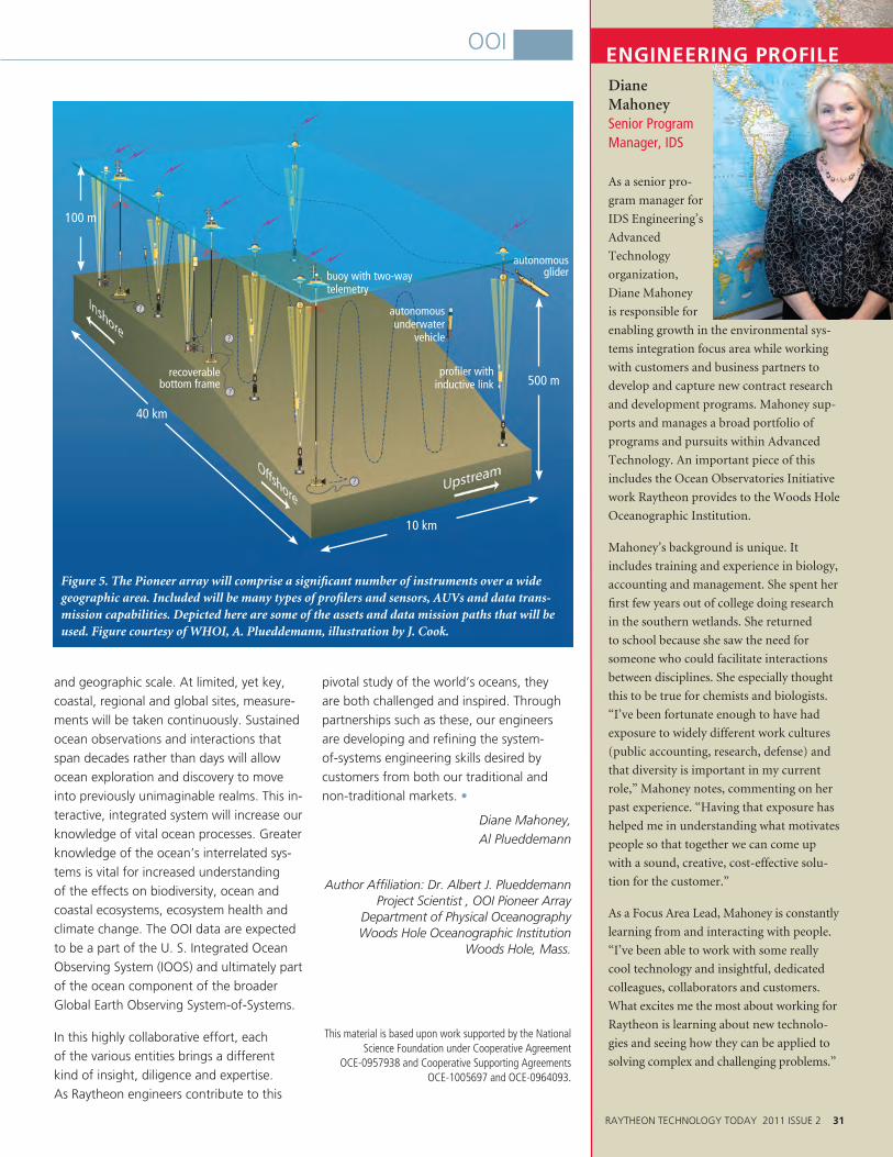
Diane Mahoney Senior Program Manager, IDS
As a senior pro-
gram manager for
IDS Engineering’s
Advanced
Technology
organization,
Diane Mahoney
is responsible for
enabling growth in the environmental sys-
tems integration focus area while working
with customers and business partners to
develop and capture new contract research
and development programs. Mahoney sup-
ports and manages a broad portfolio of
programs and pursuits within Advanced
Technology. An important piece of this
includes the Ocean Observatories Initiative
work Raytheon provides to the Woods Hole
Oceanographic Institution.
Mahoney’s background is unique. It
includes training and experience in biology,
accounting and management. She spent her
first few years out of college doing research
in the southern wetlands. She returned
to school because she saw the need for
someone who could facilitate interactions
between disciplines. She especially thought
this to be true for chemists and biologists.
“I’ve been fortunate enough to have had
exposure to widely different work cultures
(public accounting, research, defense) and
that diversity is important in my current
role,” Mahoney notes, commenting on her
past experience. “Having that exposure has
helped me in understanding what motivates
people so that together we can come up
with a sound, creative, cost-effective solu-
tion for the customer.”
As a Focus Area Lead, Mahoney is constantly
learning from and interacting with people.
“I’ve been able to work with some really
cool technology and insightful, dedicated
colleagues, collaborators and customers.
What excites me the most about working for
Raytheon is learning about new technolo-
gies and seeing how they can be applied to
solving complex and challenging problems.”
ENGINEERING PROFILE
RAYTHEON TECHNOLOGY TODAY 2011 ISSUE 2 31
OOI
and geographic scale. At limited, yet key, coastal, regional and global sites, measure-ments will be taken continuously. Sustained ocean observations and interactions that span decades rather than days will allow ocean exploration and discovery to move into previously unimaginable realms. This in-teractive, integrated system will increase our knowledge of vital ocean processes. Greater knowledge of the ocean’s interrelated sys-tems is vital for increased understanding of the effects on biodiversity, ocean and coastal ecosystems, ecosystem health and climate change. The OOI data are expected to be a part of the U. S. Integrated Ocean Observing System (IOOS) and ultimately part of the ocean component of the broader Global Earth Observing System-of-Systems.
In this highly collaborative effort, each of the various entities brings a different kind of insight, diligence and expertise. As Raytheon engineers contribute to this
pivotal study of the world’s oceans, they are both challenged and inspired. Through partnerships such as these, our engineers are developing and refining the system-of-systems engineering skills desired by customers from both our traditional and non-traditional markets. •
Diane Mahoney, Al Plueddemann
Author Affiliation: Dr. Albert J. Plueddemann Project Scientist , OOI Pioneer Array
Department of Physical Oceanography Woods Hole Oceanographic Institution
Woods Hole, Mass.
This material is based upon work supported by the National Science Foundation under Cooperative Agreement
OCE-0957938 and Cooperative Supporting Agreements OCE-1005697 and OCE-0964093.
Figure 5. The Pioneer array will comprise a significant number of instruments over a wide geographic area. Included will be many types of profilers and sensors, AUVs and data trans-mission capabilities. Depicted here are some of the assets and data mission paths that will be used. Figure courtesy of WHOI, A. Plueddemann, illustration by J. Cook.
100 m
buoy with two-way telemetry
profiler with inductive link
autonomous underwater
vehicle
autonomous glider
recoverable bottom frame 500 m
10 km
40 km
32 2011 ISSUE 2 RAYTHEON TECHNOLOGY TODAY
Feature
Climate changes in the Arctic are leading to increases in commercial shipping, oil and mineral explora-
tion, commercial fishing, tourism, research and other related activities. The U.S. Navy is the lead U.S. Department of Defense com-ponent focusing on climate change and its impact on the Arctic region. The growth of these activities requires new capabilities to execute the Navy’s missions of international cooperation, homeland security, maritime domain awareness, environmental moni-toring, humanitarian assistance, disaster response, search and rescue, and support to civil authorities.
In response to these needs, Raytheon devel-oped a situational awareness and decision support demonstration prototype software solution — Raytheon Arctic Monitoring and Prediction (RAMP). RAMP was deployed aboard the U.S. Second Fleet’s naval
destroyer USS Porter (DDG-78) during the Canadian Operation Nanook 2010 exercise.
The RAMP prototype incorporates en-vironmental data obtained from a suite of remote sensors (satellites, radars); au-tonomous sensors (data buoys, unmanned vehicles); and manned sensors (shipboard, coastal observing stations). It integrates computer-based ocean and atmospheric models with geophysical data points to provide the user with an accurate near real-time graphical display of a specific Arctic location for a given date and time. RAMP also monitors and evaluates multiple environmental factors, providing trends, analysis, prediction and decision support to aid in the safe navigation of a vessel by indicating, for example, ice-free areas and optimal shipping routes.
Operation NanookOperation Nanook1 is an exercise conducted each year by the Canadian Forces (CF) in Canada’s North. Operation Nanook 2010 was a joint operation conducted with the participation of personnel, ships and air-craft from the Canadian Army, Navy, Air and Special Forces. The 2010 exercise also included international participation from the U.S. Navy’s 2nd Fleet, the U.S. Coast Guard and the Royal Danish Navy.
The 2010 exercise took place from Aug. 6–26 in Canada’s eastern and high Arctic area as far as 75º North in Baffin Bay. It included two major components: a military exercise that focused on maintaining sover-eignty, and a whole-of-government exercise that focused on environmental containment and remediation resulting from a simulated fuel spill.
Operation Nanook – A Demonstration of Raytheon’s Situational Awareness and Decision Support System for Arctic Monitoring and Prediction
Raytheon is addressing challenges faced by environmental data pro-ducers, scientists and other users attempting to extract knowledge from a vast and rapidly growing volume of environmental infor-mation that is available from diverse sources. Raytheon’s uFrame (universal framework) service-oriented architecture (SOA) provides a data-agnostic services framework to solve this problem. This frame-work is capable of ingesting, fusing and displaying a wide array of environmental data. It is the free and open source software services solution derived from AWIPS II software being delivered by Raytheon to the National Weather Service (NWS).
Raytheon's uFrame system architecture is optimized for environmental system applications in several significant ways.
• Itisnon-proprietary,dependingonlyonleadingopen-source software packages.
• Itprovideshigh-performancedataservicesusingadvanced data serialization techniques to enable gaming-style operator interactions with dynamic data updates.
• Thevisualizationforsituationalawarenessanddecisionmakingis very adaptable and performs geographic information system (GIS)projections of all data faster than any commercial system.
• Visualizationiscustomizableatthebase/site/userlevelthroughXML files and scripts that can give users a completely tailored view of the data and concept of operations.
• ItisdesignedtoprovidewarningsandreportsquicklythroughGISinteractions and automated text generation.
• Itisplug-and-playadaptabletoavarietyofdatatypes.TheNWSAWIPS II implementation has 33 data types from large imagery data streams, text-based reports, point observations, radar data, and large arrays of scientific data from super computer weather forecast models.
• Theimplementationhasbeendesignedtodealwithalarge, complex enterprise. The NWS has 20 large national centers, 122 regional centers and many loosely connected field users. The software is customizable from a single set of installers to each of these centers and up to 4,000 individual users.
Figure 1 depicts the current end-to-end uFrame system architecture. Use of Open Geospatial Consortium standards such as Web Map Services, Web Feature Services, Sensor Web Enablement and emerg-ing standards such as Geosynchronization allow uFrame to provide network enabled sensor access and network enabled services for decision makers and C2 systems.
Raytheon Develops uFrame™ System Architecture to Provide Environmental Data Analysis

RAYTHEON TECHNOLOGY TODAY 2011 ISSUE 2 33
Feature
RequirementThe Arctic occupies by far the largest area of responsibility for the CF, spanning across 40 percent of Canada’s total land mass and 75 percent of its coastal regions. The Arctic monitoring and prediction system was developed to provide a vessel commander with a comprehensive and improved under-standing of the current and predicted Arctic physical environment. This is achieved by integrating, correlating and analyzing data accumulated from a wide variety of accred-ited sources in order to provide situational awareness and decision support for both tactical and operational missions. In addi-tion, the software was required to provide current and future weather information and oceanographic data in an integrated visual format.
Architecture The RAMP solution has been developed using a service-oriented architecture (SOA). The SOA defines interfaces in terms of pro-tocols and functionality and permits the integration of widely disparate
applications and sensors into a Web-based environment, and supports multiple imple-mentation platforms.
The architecture is illustrated in Figure 1. The core of the system is Raytheon’s uFrameTM (universal framework) SOA that
is the basis for the U.S. National Weather Service Advanced Weather Interactive Processing System (AWIPS) II program. Key features of the uFrame SOA include an extensible, flexible, tailorable, rapidly con-figurable framework that enables rapid
continued on page 34
is implemented as a plug-in. The plug-in pattern makes the server plug-and-play adaptable for all data types desired. The server piece can scale from a laptop to a cluster of servers depending on the data volumes. Services in the framework ingest, extract metadata, de-code, and save the data to high-performance file storage.
The visualization framework provides user interface services. This component allows the creation of tailored user perspectives, menus, displays and screen interactions based on user required data render-ing and data analysis. Web-based clients such as Google Earth™ mapping service or NASA World Wind can be used for situational awareness if detailed data analysis is not required.
Using this framework, Raytheon can rapidly respond to end user needs for new features and capabilities. Prototype data plug-ins have been developed in as little as two days. For Operation Nanook, a complete mission capability set (called mission packs) advanced from engineering concept to fielded capability in 83 business days, dem-onstrating the responsiveness customers are seeking. •
Bob Bowne Contributors: Tim Raglin, Matt Payne
The services framework contains the design pattern and mechanisms to ingest, index, persist and make available all data. Each data type
Services Framework
Plug Ins
Open Geospatial ConsortiumMachine-to-Machine Interface
Fixed-SiteUser Interface
Services
Hand-HeldServices
and Clients
Visualization Framework
Sensor Interfaces in Standard Formats• Imagery • Video • Radar Data • Environmental Sensor Data
ENTERPRISE SERVICE BUS
uFrame Architecture
• Tailored User Perspectives• Configurable Menus• Interactive Displays• Data Rendering & Analysis• Gaming Visualization
High PerformanceFile Storage
DataTransformer
ExternalDatabases
User
Applications
Plug-In
Extendable
Figure 1. The Raytheon uFrame system architecture includes a services framework to process data and a visualization framework for display and analysis.
1http://www.canadacom.forces.gc.ca/daily/archive-nanook10-eng.asp, Modified: 2011-02-17
Figure 1. The architecture of the Arctic monitoring and prediction software is Raytheon’s uFrame.
IMAGERYSERVICEADAPTER
VIDEOSERVICEADAPTER
RADARSERVICEADAPTER
SONARSERVICEADAPTER
ENVIRONMENTALDATA SERVICE
ADAPTER
E N V I R O N M E N T A L S E N S O R S
NaturalResources
EnergyImpacts
ClimateChanges
NationalSecurity Sea Level
RiseShipping
Lanes
Search andRescue
Ocean FloorMapping
Ice ExtentPredictions Comms Human
Impacts Tourism
A N A LY S I S
VISUALIZATION
uFrame™ Plug and PlayService Oriented Architecture (SOA)
INTERFACE REGISTRYServices
AUTOMATE STORE

34 2011 ISSUE 2 RAYTHEON TECHNOLOGY TODAY
Feature
continued from page 33
plug and play of new data types, models and sensors. It also geospatially aligns infor-mation to enable layering and analysis and includes gaming-style visualization to ma-nipulate and interact with the data.
CapabilitiesRAMP software continuously monitors en-vironmental conditions in near real time. It is designed to rapidly integrate, visualize and analyze a wide variety of data based on end-user needs. For the Nanook 2010 ex-ercise it was configured to ingest data from the following sources:
• ModerateResolutionImagingSpectrora-diometer (MODIS) and Synthetic Aperture Radar (SAR) imagery (TerraSAR-X).
• Advancedmicrowavescanning radiometer (AMSR-E).
• CanadianIceServiceandU.S.National Ice Center (NIC) image analysis charts, called “egg charts.”
• Historicalicedata(1870topresentday).
• Weatherobservations.
• Shiplocationscollectedviasatellite.
The software was then used to transform this data into knowledge.
DemonstrationIn support of the Nanook 2010 exercise, the Arctic monitoring and prediction software was configured to provide near real-time SAR and MODIS data overlays. It also pro-vided multiple data sets, such as MODIS, SAR, AMSR-E, ice data, weather observa-tions and ship Automatic Identification System (AIS) locations to be integrated onto a single screen. This unique collection of data allowed the commander to see the “big picture” and make appropriate deci-sions in an informed and timely manner.
The RAMP display allowed the operator to quickly see ocean conditions at night as well as in foggy and overcast conditions. RAMP software also calculated the shortest, safest path based on ice conditions, ocean depth, ship size and hull strength, thereby assisting
in the safe navigation of the vessel through icy and shallow waters.
ResultsThe RAMP protoytpe demonstrated how disparate data could be fused to provide decision support.
This fusion is demonstrated in Figures 2 and 3. Figure 2 shows the USS Porter in St. John’s Harbor, Newfoundland, Canada, on Aug. 1, 2010. The low overcast conditions seen in the picture were typical of the environmen-tal conditions experienced throughout the exercise. Cloud cover and fog prevented ocean imaging through the use of traditional electro-optical sensor collection.
Figure 3 shows sensor collections from Earth Observation Satellite MODIS and the TerraSAR-X, X-Band Synthetic Aperture Radar. The MODIS ice/snow image on the left shows cloud cover over eastern Newfoundland, with the TerraSAR-X SAR
image of the St. John’s Harbor area geolocated and overlaid. The right side shows the cloud-penetrating surface imaging available when using the TerraSAR-X sensor.
Being able to provide these images to the vessel commander and to the NIC in a timely manner demonstrated a new level of situational awareness, enabling a ship without an ice-reinforced hull to safely par-ticipate in the Nanook 2010 exercise and effectively perform its mission.
The prototype RAMP solution was opera-tionally deployed onboard the USS Porter for the period of the Nanook 2010 exer-cise and it was shown to be an essential asset for operation in the far north. Work is underway to provide additional capabil-ity in support of future exercises, including potential deployment on other participating vessels. •
Tony Ponsford, Bob Bowne
NANOOK
Figure 2. USS Porter in St. John’s Harbor, Newfoundland, Canada Aug. 1, 2010
Figure 3. MODIS ice/snow and TerraSAR-X imagery of St. John’s, Newfoundland (left), and zoomed view of TerraSAR-X imagery collected on Aug. 1

RAYTHEON TECHNOLOGY TODAY 2011 ISSUE 2 35
Antarctica has come to symbolize one of the last, great frontiers for science — a natural laboratory
for oceanography, glaciology, biology, astrophysics and a host of other research endeavors.
Maintaining a pristine environment — un-sullied from pollution and degradation from human activities — is one of the chief goals of the nations that operate in its biologi-cally and geologically diverse areas, on its ice sheets and near its shores. While no one nation owns this massive continent, dozens cooperate through the Antarctic Treaty system to conduct research and man-age environmental impacts. Environmental protection of Antarctica has been a cor-nerstone of international policy since the 1960s, and many areas of special interest to scientists and historians enjoy additional safeguards under various designations that dictate how national programs manage these sites.
Since 2000, Raytheon Polar Services has been the prime contractor to the National Science Foundation’s (NSF) Office of Polar Programs for the U.S. Antarctic Program. Among its many support responsibilities, Raytheon plays the important role of environmental steward, ensuring adherence to environmental pro-tocols at each U.S. research station, at field camps and on the research vessels. In May of this year, Raytheon Polar Services received an award from the NSF for outstanding service and dedication to the United States Antarctic Program and for its role in protecting the Antarctic environment.
Leading the Way for Environmental ProtectionRaytheon has done more than just ensure adherence to Antarctic Treaty requirements; we strive to lead the way in the area of environmental protection. For example, the McMurdo Dry Valleys, a relatively ice-free area that is the site of a number of scientific studies, has a series of ice-covered lakes that
contain endemic microor-ganisms. Some of these species occur in one lake but not in another, so scientists who study these ecosystems risk transport-ing a species from lake to lake. For this reason, Raytheon’s management plans include additional provisions, such as requir-ing personnel to sanitize boots before working in each lake, to prevent non-native species or cross-species contamina-tion of neighboring sites.
Other examples of Raytheon’s leadership in support of environmental protection and conservation in Antarctica include:
• Recycling and reuse. Participants in Antarctica sort their waste into about 14 categories. Even potato peelings are returned to the United States. We return 100 percent of waste for recycling, disposal or auction.
• Waste-heat recovery. The McMurdo Station power plant was recently ex-panded and upgraded to be more effi-cient. The system is able to capture most of the waste heat, which is used to heat other structures.
• Use of alternative energy. A new tur-bine farm was constructed on Ross Island, with logistical support from Raytheon. Solar power/thermal panels and small wind turbines are being tested and used for remote field camps and for temporary housing at the South Pole Station. Elec-tric lightweight utility vehicles are being tested at McMurdo Station to learn how they hold up in the harsh conditions.
• Energy conservation. Upgrades to more efficient lighting, plumbing fixtures, vari-able speed motors, etc., are routinely made at all stations.
• Construction of the South Pole Traverse. A 1,000-mile compacted snow road in Antarctica links the United States’ McMurdo Station on the coast to the Amundsen-Scott South Pole Station (Figure 1). A “tractor train” travels this route each summer season to deliver fuel, cargo and equipment, traveling across a Texas-sized ice shelf and up a glacier that cuts through the Transantarctic Mountains. The traverse also brings trash
continued on page 36
Adélie penguins being studied at Cape Hallett, along the Borchgrevink Coast, Antarctica. Photo by Jessy Jenkins
Environmental Technology on “The Ice” Raytheon’s Antarctic Support Role
Figure 1. Map of the Antarctic region
MCMURDOSTATION (USA)
SOUTH POLETRAVERSE
Feature
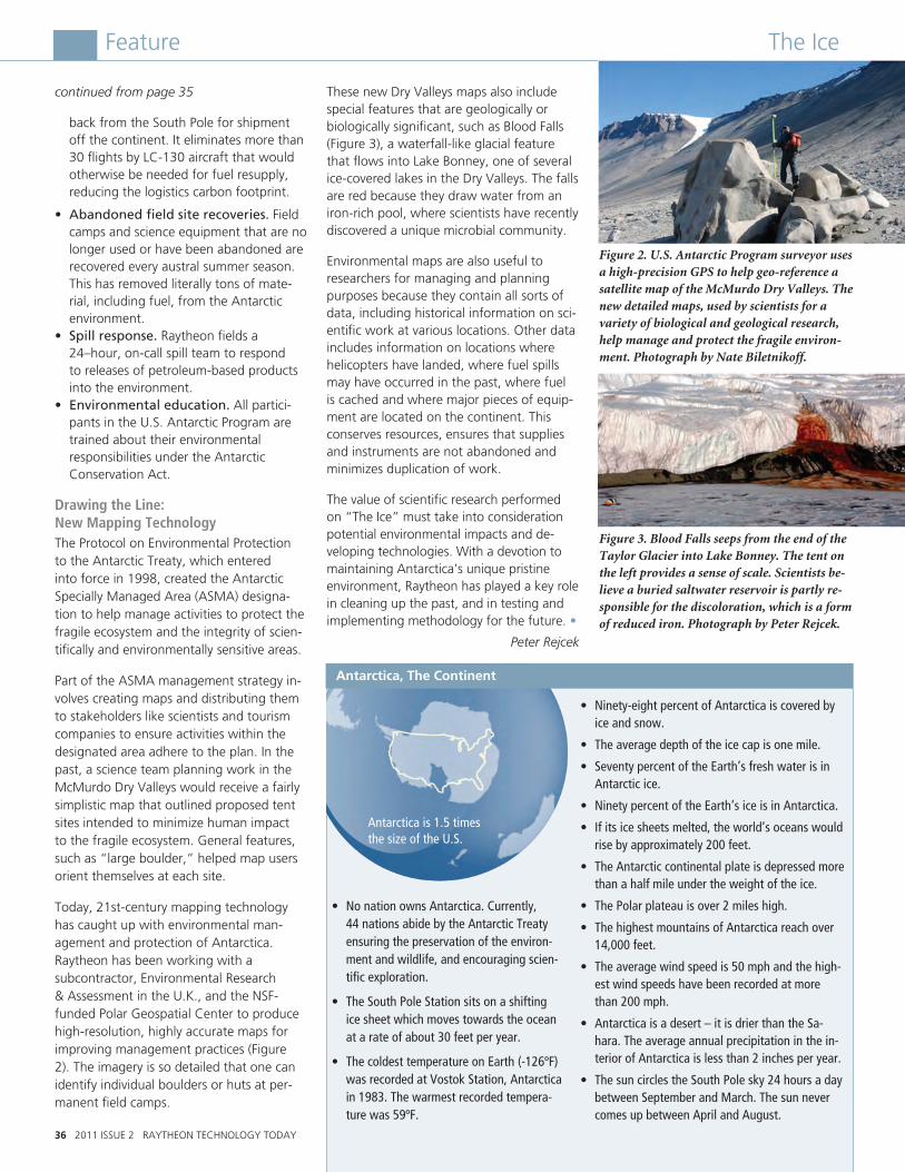
The IceFeature
continued from page 35
back from the South Pole for shipment off the continent. It eliminates more than 30 flights by LC-130 aircraft that would otherwise be needed for fuel resupply, reducing the logistics carbon footprint.
• Abandoned field site recoveries. Field camps and science equipment that are no longer used or have been abandoned are recovered every austral summer season. This has removed literally tons of mate-rial, including fuel, from the Antarctic environment.
• Spill response. Raytheon fields a 24–hour, on-call spill team to respond to releases of petroleum-based products into the environment.
• Environmental education. All partici-pants in the U.S. Antarctic Program are trained about their environmental responsibilities under the Antarctic Conservation Act.
Drawing the Line: New Mapping Technology The Protocol on Environmental Protection to the Antarctic Treaty, which entered into force in 1998, created the Antarctic Specially Managed Area (ASMA) designa-tion to help manage activities to protect the fragile ecosystem and the integrity of scien-tifically and environmentally sensitive areas.
Part of the ASMA management strategy in-volves creating maps and distributing them to stakeholders like scientists and tourism companies to ensure activities within the designated area adhere to the plan. In the past, a science team planning work in the McMurdo Dry Valleys would receive a fairly simplistic map that outlined proposed tent sites intended to minimize human impact to the fragile ecosystem. General features, such as “large boulder,” helped map users orient themselves at each site.
Today, 21st-century mapping technology has caught up with environmental man-agement and protection of Antarctica. Raytheon has been working with a subcontractor, Environmental Research & Assessment in the U.K., and the NSF-funded Polar Geospatial Center to produce high-resolution, highly accurate maps for improving management practices (Figure 2). The imagery is so detailed that one can identify individual boulders or huts at per-manent field camps.
These new Dry Valleys maps also include special features that are geologically or biologically significant, such as Blood Falls (Figure 3), a waterfall-like glacial feature that flows into Lake Bonney, one of several ice-covered lakes in the Dry Valleys. The falls are red because they draw water from an iron-rich pool, where scientists have recently discovered a unique microbial community.
Environmental maps are also useful to researchers for managing and planning purposes because they contain all sorts of data, including historical information on sci-entific work at various locations. Other data includes information on locations where helicopters have landed, where fuel spills may have occurred in the past, where fuel is cached and where major pieces of equip-ment are located on the continent. This conserves resources, ensures that supplies and instruments are not abandoned and minimizes duplication of work.
The value of scientific research performed on “The Ice” must take into consideration potential environmental impacts and de-veloping technologies. With a devotion to maintaining Antarctica’s unique pristine environment, Raytheon has played a key role in cleaning up the past, and in testing and implementing methodology for the future. •
Peter Rejcek
36 2011 ISSUE 2 RAYTHEON TECHNOLOGY TODAY
Figure 2. U.S. Antarctic Program surveyor uses a high-precision GPS to help geo-reference a satellite map of the McMurdo Dry Valleys. The new detailed maps, used by scientists for a variety of biological and geological research, help manage and protect the fragile environ-ment. Photograph by Nate Biletnikoff.
Figure 3. Blood Falls seeps from the end of the Taylor Glacier into Lake Bonney. The tent on the left provides a sense of scale. Scientists be-lieve a buried saltwater reservoir is partly re-sponsible for the discoloration, which is a form of reduced iron. Photograph by Peter Rejcek.
Antarctica, The Continent
Antarctica is 1.5 times the size of the U.S.
• Ninety-eightpercentofAntarcticaiscoveredbyice and snow.
• Theaveragedepthoftheicecapisonemile.
• SeventypercentoftheEarth’sfreshwaterisinAntarctic ice.
• NinetypercentoftheEarth’siceisinAntarctica.
• Ifitsicesheetsmelted,theworld’soceanswouldrise by approximately 200 feet.
• TheAntarcticcontinentalplateisdepressedmorethan a half mile under the weight of the ice.
• ThePolarplateauisover2mileshigh.
• ThehighestmountainsofAntarcticareachover14,000 feet.
• Theaveragewindspeedis50mphandthehigh-est wind speeds have been recorded at more than 200 mph.
• Antarcticaisadesert–itisdrierthantheSa-hara. The average annual precipitation in the in-terior of Antarctica is less than 2 inches per year.
• ThesuncirclestheSouthPolesky24hoursadaybetween September and March. The sun never comes up between April and August.
• NonationownsAntarctica.Currently, 44 nations abide by the Antarctic Treaty ensuring the preservation of the environ-ment and wildlife, and encouraging scien-tific exploration.
• TheSouthPoleStationsitsonashiftingice sheet which moves towards the ocean at a rate of about 30 feet per year.
• ThecoldesttemperatureonEarth(-126ºF)was recorded at Vostok Station, Antarctica in 1983. The warmest recorded tempera-turewas59ºF.
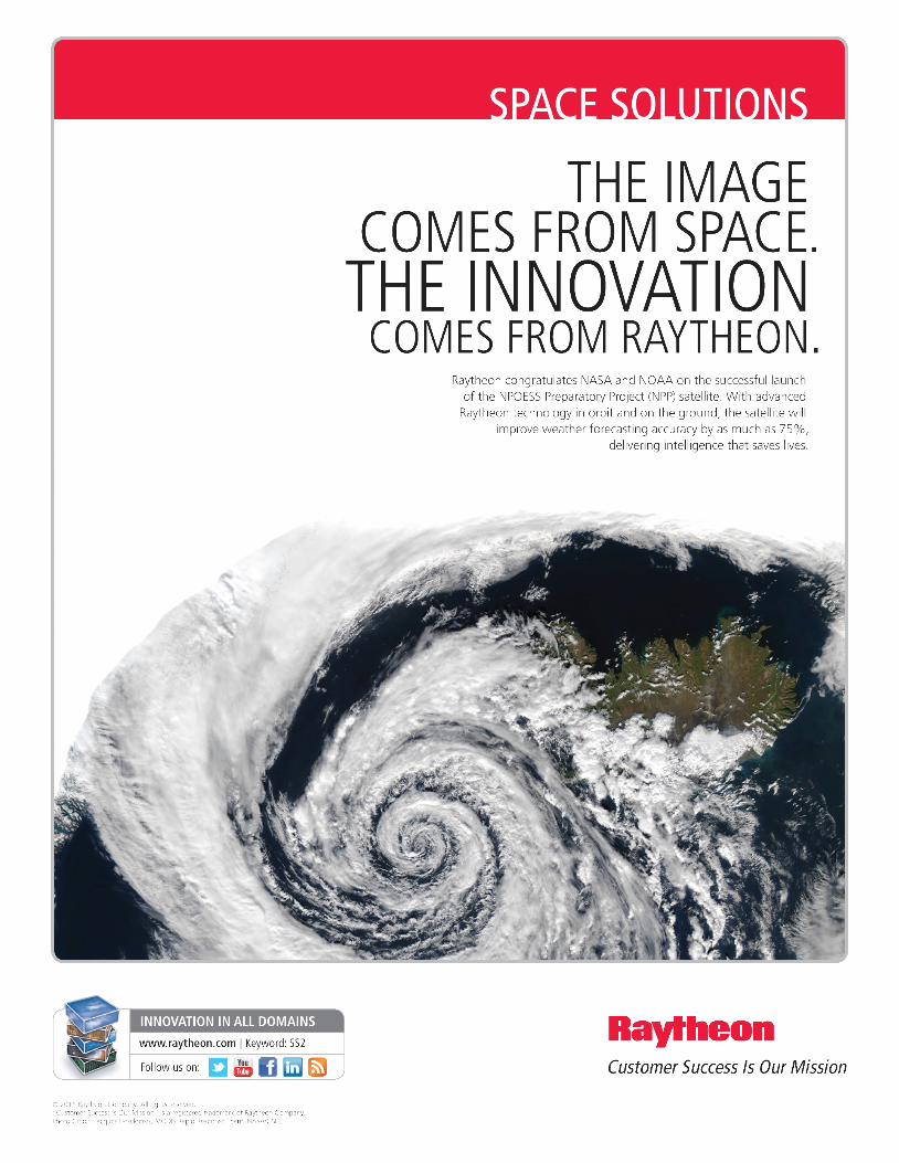
Raytheon has had a robust waste reduction and recycling program since the 1970s that has evolved over the years to become best-in-class. Reducing waste and maximizing recycling has become part of Raytheon’s culture. As a result of our efforts across the enterprise, we have been recognized by nu-merous state, local and federal organizations for our exemplary waste reduction efforts.
As of year-end 2010, our companywide recycling rate for solid waste was 64 per-cent. Since 1998, we have reduced our generation of solid waste by 58 percent, normalized by revenue. In 2008, we set a long-term sustainability goal to reduce the volume of landfill and incinerated solid waste by 25 percent by 2013; as of year-end 2010, we achieved a 17 percent reduction, normalized by revenue.
We continue to “green” not only our op-erations, but also our dining facilities. Over the last several years, we have purged our dining facilities of polystyrene and replaced to-go meal packaging with environmentally preferable materials that are compostable. During 2010, we composted more than 569 tons of organic materials that were
incorporated into landscaping materials. We now encourage the use of reusable din-ing ware in our facilities to reduce waste generation. Our New England facilities led the way on these initiatives, and they are now propagating to Raytheon facili-ties across the country and in the United Kingdom. Our Aurora, Colo. facility led the way in composting pulverized paper generated from on-site disintegration of classified documents.
Since 2008, we reduced our use of potable water by 15 percent, saving more than 190 million gallons of water. Across the com-pany, we use more than 54 million gallons of recycled water annually. Our California locations alone use 39 million gallons. Our locations have begun the installation of smart irrigation systems, which use a com-puter controller that takes into account past and predicted precipitation events. These systems help to minimize irrigation water demand across the company. We continue to pursue additional water reduction tech-niques and equipment, including cooling tower upgrades, low-flow plumbing fixtures and process modifications.
Raytheon’s energy conservation pro-gram has been in place since the 1970s. Minimizing energy use has always been a priority for our company. We have been a charter member of the U.S. Environmental Protection Agency’s (EPA) Climate Leaders® program since 2002. Since that year, Raytheon has reduced absolute greenhouse gas emissions by 21 percent, eliminating more than 570,000 metric tons of green-house gas emissions cumulatively. Since 2008, Raytheon has bought 31,000 mega-watt hours of green electricity in the form of renewable energy certificates. For the fourth consecutive year, the EPA awarded Raytheon the 2011 ENERGY STAR® Award for Sustained Excellence in Energy Management. We continue to pursue our long-term goal of an additional absolute 10 percent reduction of greenhouse gas emissions by 2015.
We are also partnering with our office sup-plier, Staples®, on numerous sustainability initiatives, including packaging reduction, responsible end-of-life electronics manage-ment, toner and ink cartridge recycling, and a reduction in vehicle trips to our facilities by eliminating one day each week of deliveries. •
Frank Marino
38 2011 ISSUE 2 RAYTHEON TECHNOLOGY TODAY
Feature
Raytheon has a long history of environmental stewardship. The company has employed dedicated environmental and energy staff positions at corporate headquarters and operating locations since 1970. Raytheon’s sustainability program underscores our commitment to future generations by engaging our employees, customers, suppliers and communities to protect our environment and conserve natural resources.
Strategic environmental focus areas:
•Recyclingandwasteminimization
•Greenhousegasemissionreductions
•Energyefficiency
•Waterconservation
•Designforsustainability
•Eco-friendlysupplychain
•Environmentalstewardship
Highlighted in the following sections are just a few examples of our ongoing sustainability initiatives.
Recycling and Waste Minimization
Preserving the Environment for Future Generations

Approximately 70 percent of the electricity in the U.S. is generated using fossil fuels, mainly coal and natural gas. Burning fossil fuels for power generation is the nation’s single largest source of industrial air pol-lution, and it is the leading contributor of greenhouse gas emissions. Despite advances in renewable energy during the last decade, less than three percent of U.S. electricity comes from renewable energy sources such as wind, solar, hydro or biomass projects.
Electricity markets have changed over time and now offer some consumers the ability to buy power that is generated from renew-able sources, or green power, primarily from wind farms. Buying green power reduces the company’s carbon footprint. Supporting renewable energy also assists in promoting energy security and energy independence, two increasingly important national security goals.
Five North Texas Raytheon sites are buying approximately 25 percent of their electricity, — about 24,000 MWh a year — from one particular renewable energy project located at a solid waste landfill. The McKinney, Texas, landfill used for this project is a closed landfill, meaning it no longer accepts materials. Electricity is generated using bio-gas (methane) a renewable energy source from the landfill. Natural gas that is burned in our heaters, boilers and gas ranges con-
tains 70 to 90 percent methane. Buying this green power will reduce our greenhouse gas emissions by 12,000 metric tons a year — a 20 percent reduction of the five sites’ total greenhouse gas emissions.
Raytheon will purchase 100 percent of the green electricity that is generated from this landfill gas project through a regional retail energy provider. Raytheon’s agreement to purchase the electricity was a driving fac-tor for the construction of the renewable
energy project. The biogas from the landfill is generated from the slow decomposition of organic waste materials. It is primarily composed of methane gas, which has a global warming potential 21 times higher than carbon dioxide, the most common greenhouse gas.
The process, shown in Figure 1, is conceptu-ally very simple: Extract the biogas from the landfill through a piping network, compress
the gas to a usable pressure and remove impurities like water vapor. The gas is then combusted in an engine that drives the generator to create electricity, which is then supplied to the electrical distribution grid. The byproducts from the methane combus-tion are carbon dioxide — a less potent greenhouse gas — and water. Capturing and combusting the biogas from the landfill minimizes odors and destroys other undesir-able gasses that may otherwise be released to the environment. The real advantage, however, is that the methane is consumed with no net greenhouse gas emissions. This means that the same amount of carbon that was previously absorbed or sequestered by the organics during their life cycle is then released during decomposition and combus-tion. So the process benefits Raytheon, the electricity provider, the community and the environment. •
Reese Brentzel
RAYTHEON TECHNOLOGY TODAY 2011 ISSUE 2 39
Feature
Figure 1. Schematic of the process of using biogas to create clean renewable energy.
Landfill Gas Pretreatment
InletSeparator
Landfill Gas
CompressorMethane Gas
EngineGeneratorSet
ElectricUtility
From Trash to Clean Renewable Power
continued on page 40
Preserving the Environment for Future Generations

continued from page 39
Reducing Energy Use of Environmental Test ChambersSome of the largest consumers of electricity at one of our Raytheon North Texas sites are the environmental test chambers used for thermal testing of our products. These chambers are used to test products such as circuit cards, night vision rifle sights, rocket launchers, and airborne surveillance and targeting systems. Products are tested in temperatures ranging between 75 degrees Celsius and minus 65 degrees Celsius to ensure they perform properly across a wide range of environmental conditions.
A typical chamber employs two 30-horse-power motors/compressors to cool the system. These compressors are properly sized to achieve the rapid temperature changes required. Once the temperature is reached, however, the system refrigerant is pulsed through a bypass circuit, since only a small amount of cooling is required to maintain the chamber temperature. While these compressors are running, the chamber is consuming about 40 kilowatts of power. Running almost 24 hours a day and 7 days a week, each chamber’s energy consumption can exceed 300,000 kilowatt hours per year.
In an effort to reduce this energy demand, Raytheon developed a smaller version of the standard refrigeration system that could be added to an existing chamber along with a more advanced controller to sense cooling demand. The enhanced system uses the original cooling system to accomplish rapid temperature changes, but when the cham-ber has reached its target temperature, the main cooling system is shut down and the smaller mini-cooler takes over the task of maintaining chamber conditions. This dramatically reduces the amount of electric-ity needed to perform a typical production temperature cycle.
The installation of these mini-coolers began in June 2010 and had an immediate impact on electricity usage (see Figure 2). Although results vary depending on individual test requirements, most typical applications have reduced overall electricity usage by 50 to 65 percent. At our current workload, we expect to save about 4 million kilowatt hours of electricity annually. This equates to at least 4,000 metric tons of carbon dioxide that won’t be released into the atmosphere each year, which is a significant step in pro-ducing a more sustainable factory. For each retrofitted test chamber, the reduction in carbon dioxide emissions is roughly equiva-lent to the annual emissions of 20 cars. We expect to have 50 mini-cooler units in place by the end of 2011. •
Mark Taylor
Conserving California’s Water SupplyA significant aspect of Raytheon’s Southern California operations is the extensive use of recycled water for irrigation and cooling tower make-up water (water supplied — such as to a steam boiler or cooling tower — to compensate for losses by evapora-tion). These measures save water, energy, money and the environment.
The recycled irrigation water project is conducted in collaboration with the West Basin Municipal Water District. The district treats municipal wastewater to various levels of cleanliness and then redistributes it for specific uses. The recycled water is used in various applications, including ir-rigation, groundwater discharge to prevent salt water intrusion, and oil refinery cooling towers and boilers. Raytheon uses this im-ported recycled water for campus irrigation, which saves 84-acre-feet a year of imported water — enough to fill 84 football stadiums to a one-foot depth (or 27 million gallons) annually. Use of this recycled water elimi-nates the need for the Metropolitan Water District of Southern California to import potable water from numerous surface water supplies in Northern California through an extensive aqueduct system that diverts water from the Colorado River.
Raytheon’s El Segundo campus also recycles its own wastewater with an on-site waste treatment plant. The treatment plant’s ef-fluent is used for water make-up in on-site cooling towers. This process saves more than 15 million gallons of potable water per year. Total cost savings from the use of the imported recycled water and the reuse of on-site treated water is approximately $35,000 per year.
Saving money helps Raytheon run more efficiently and aligns with our sustainability
40 2011 ISSUE 2 RAYTHEON TECHNOLOGY TODAY
Feature
2009
Feb
800,000
kilowatt hours Chamber Energy Usage
80% of mini-coolers installed
installed first mini-cooler700,000
600,000
500,000
400,000
300,000
0Apr June Aug Oct Dec Feb FebApr June Aug Oct Dec
2009 2010 2010 2011
Figure 2. The graph indicates a significant energy savings achieved by installing 40 mini-coolers in the environmental chambers at a Raytheon North Texas facility.
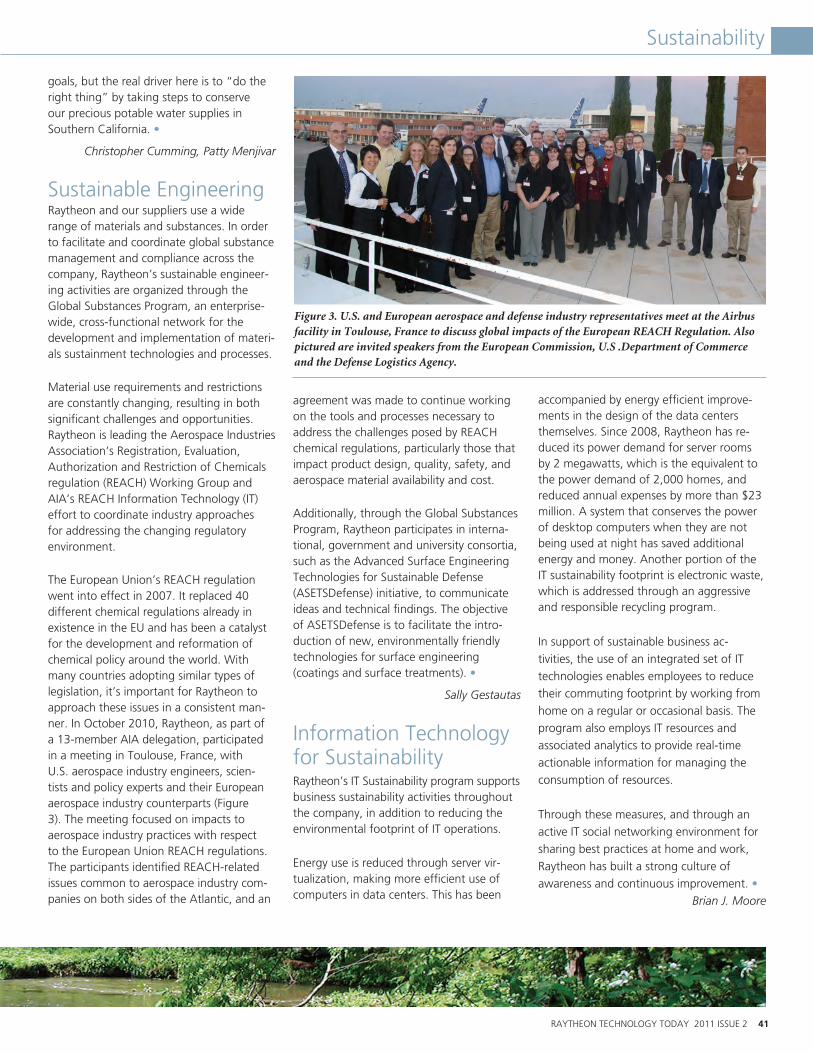
RAYTHEON TECHNOLOGY TODAY 2011 ISSUE 2 41
Sustainability
goals, but the real driver here is to “do the right thing” by taking steps to conserve our precious potable water supplies in Southern California. •
Christopher Cumming, Patty Menjivar
Sustainable EngineeringRaytheon and our suppliers use a wide range of materials and substances. In order to facilitate and coordinate global substance management and compliance across the company, Raytheon’s sustainable engineer-ing activities are organized through the Global Substances Program, an enterprise-wide, cross-functional network for the development and implementation of materi-als sustainment technologies and processes.
Material use requirements and restrictions are constantly changing, resulting in both significant challenges and opportunities. Raytheon is leading the Aerospace Industries Association’s Registration, Evaluation, Authorization and Restriction of Chemicals regulation (REACH) Working Group and AIA’s REACH Information Technology (IT) effort to coordinate industry approaches for addressing the changing regulatory environment.
The European Union’s REACH regulation went into effect in 2007. It replaced 40 different chemical regulations already in existence in the EU and has been a catalyst for the development and reformation of chemical policy around the world. With many countries adopting similar types of legislation, it’s important for Raytheon to approach these issues in a consistent man-ner. In October 2010, Raytheon, as part of a 13-member AIA delegation, participated in a meeting in Toulouse, France, with U.S. aerospace industry engineers, scien-tists and policy experts and their European aerospace industry counterparts (Figure 3). The meeting focused on impacts to aerospace industry practices with respect to the European Union REACH regulations. The participants identified REACH-related issues common to aerospace industry com-panies on both sides of the Atlantic, and an
agreement was made to continue working on the tools and processes necessary to address the challenges posed by REACH chemical regulations, particularly those that impact product design, quality, safety, and aerospace material availability and cost.
Additionally, through the Global Substances Program, Raytheon participates in interna-tional, government and university consortia, such as the Advanced Surface Engineering Technologies for Sustainable Defense (ASETSDefense) initiative, to communicate ideas and technical findings. The objective of ASETSDefense is to facilitate the intro-duction of new, environmentally friendly technologies for surface engineering (coatings and surface treatments). •
Sally Gestautas
Information Technology for SustainabilityRaytheon’s IT Sustainability program supports business sustainability activities throughout the company, in addition to reducing the environmental footprint of IT operations.
Energy use is reduced through server vir-tualization, making more efficient use of computers in data centers. This has been
accompanied by energy efficient improve-ments in the design of the data centers themselves. Since 2008, Raytheon has re-duced its power demand for server rooms by 2 megawatts, which is the equivalent to the power demand of 2,000 homes, and reduced annual expenses by more than $23 million. A system that conserves the power of desktop computers when they are not being used at night has saved additional energy and money. Another portion of the IT sustainability footprint is electronic waste, which is addressed through an aggressive and responsible recycling program.
In support of sustainable business ac-tivities, the use of an integrated set of IT technologies enables employees to reduce their commuting footprint by working from home on a regular or occasional basis. The program also employs IT resources and associated analytics to provide real-time actionable information for managing the consumption of resources.
Through these measures, and through an active IT social networking environment for sharing best practices at home and work, Raytheon has built a strong culture of awareness and continuous improvement. •
Brian J. Moore
Figure 3. U.S. and European aerospace and defense industry representatives meet at the Airbus facility in Toulouse, France to discuss global impacts of the European REACH Regulation. Also pictured are invited speakers from the European Commission, U.S .Department of Commerce and the Defense Logistics Agency.
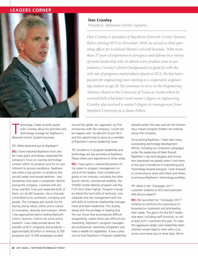
42 2011 ISSUE 2 RAYTHEON TECHNOLOGY TODAY42 2011 ISSUE 2 RAYTHEON TECHNOLOGY TODAY
Dan CrowleyPresident, Network Centric Systems
T echnology Today recently spoke with Crowley about his priorities and technology strategy for Raytheon’s
Network Centric Systems business.
TT: What attracted you to Raytheon?
DC: I have watched Raytheon from afar for many years and always respected the company’s focus on owning technology content within its products and for its com-mitment to process excellence. Raytheon was often a key partner on products like aircraft radars and missile defense – and sometimes they were a competitor. Before joining the company, I worked with Jon Jones and Rick Yuse and respected both of them, as I do Bill Swanson. He is intensely committed to his customers, company and people. The company also stands out for having strong values, ethics and a culture of innovation, diversity and inclusion. When I was approached about leading Network Centric Systems, I had to do some online research. I was really excited about the breadth of NCS’ programs and products — approximately $5 billion in revenue, 6,700 programs and 13,300 employees located
around the globe. As I approach my first anniversary with the company, I could not be happier with my decision to join NCS and the opportunity to serve as a member of Raytheon’s senior leadership team.
TT: Excellence in program leadership and technology are top priorities at Raytheon. Please share your experience in these areas.
DC: I have spent a substantial portion of my career in program management on some of the largest, most complex pro-grams in our industry, including the Atlas launch vehicle, commercial satellites, the THAAD missile defense program and the F-35 Joint Strike Fighter. Program manag-ers blend the hard skills of technical, cost, schedule and risk management with the soft skills of customer relationship manage-ment and team leadership. This duality, along with the privilege of leading and the scar tissue that accompanies difficult assignments, makes these jobs difficult but rewarding. Raytheon’s program managers are professional, extremely competent and have a wealth of capabilities. It was a plea-sure to host Raytheon’s Program Leadership
Awards earlier this year and see the tremen-dous impact program leaders are making across the company.
Since joining Raytheon, I have seen many outstanding technology development efforts, including our enterprise campaigns under the leadership of Mark Russell. Raytheon’s top technologists and innova-tors impressed me greatly when I met them at this year's Excellence in Engineering and Technology Awards banquet. I look forward to continuing to work with Mark and others to enhance Raytheon’s technology portfolio.
TT: What is the “Campaign 2011” customer initiative at NCS and what ben-efits do you expect?
DC: We launched the “Campaign 2011” initiative to reinforce the importance of knowing our customers and anticipating their needs. The goal is for the NCS leader-ship team, including staff functions, to visit at least 2,011 customers this year. To meet this aggressive target, each leadership team member would need to meet with a cus-tomer once every two or three days. We’re
Dan Crowley is president of Raytheon Network Centric Systems.
Before joining NCS in November 2010, he served as chief oper-
ating officer for Lockheed Martin’s aircraft business. With more
than 27 years of experience in aerospace and defense in a variety
of senior leadership roles in almost every product area in our
industry, Crowley’s diverse background is a great fit with the
rich mix of programs and products found at NCS. He has had a
passion for engineering since starting as a cooperative engineer-
ing student at age 20. He continues to serve on the Engineering
Advisory Board at the University of Texas at Austin where he
received both a bachelor’s and master’s degree in engineering.
Crowley also received a master’s degree in management from
Stanford University as a Sloan Fellow.
LEADERS CORNER

Feature
all working hard at this; it’s easy to go weeks without seeing a customer in person.
I believe that everyone in NCS is in busi-ness development, and to be successful, we must have the best possible customer relationships. Everyone plays a part in understanding and addressing customer needs and expectations, and in identifying new opportunities.
TT: With the breadth of NCS’ business port-folio and a changing business environment (slower DoD growth and more international opportunities), how are you reshaping NCS business strategies?
DC: Winning companies do not wish for things to be the way they were; rather they find ways to adapt to and exploit new reali-ties, and that’s our attitude at NCS. Though today’s uncertainties and the dynamic world environment are creating challenges for our business, NCS has the franchises and capa-bilities to make opportunities from these challenges.
In NCS, we are positioning ourselves for growth by analyzing our markets, evaluat-ing our differentiators and adjusting our vision, mission and strategy for success. Our new vision is to “help protect lives and ensure customer success through innovative, net-enabled solutions.” We will accomplish this by providing new and innovative products, solutions and services that tap the “Power of the Network.” By engaging the power of our global team and delivering interoperable, scalable solutions, we will help our customers achieve mission success and enable them to make critical decisions with speed and accuracy.
Each of NCS’ six product lines has their own specific technology and product strategies, but this unifying strategy for growth will shape our investments and pursuits, and ultimately our success.
TT: The ability to develop people is an im-portant skill for any business leader. What have you found to be effective ?
DC: I love how Raytheon places so much emphasis on leadership development and
offers such extensive training. Still, much of the responsibility falls on our own shoulders for self-development and helping those under our responsibility. I read extensively on the subject of leadership, and I am a student of the pioneering industrialists like Henry Ford and Thomas Edison. They had a vision for the future and engaged others in this vision, and great results followed. The next step is to build a strategy that is aligned with the needs of the customer and the company — including forming the team needed for success. Once the right people are in the right positions, my focus is to pro-vide timely, specific feedback that reinforces that impact of people’s behavior, good or bad. Annual development reviews help, but ongoing feedback has worked best for me. I also try to lead by example because people watch your hips not your lips.
TT: What is NCS doing, both internally and externally, to make a difference in the envi-ronment?
DC: A young man was once encouraged to “Buy land — they are not making any more of this stuff.” The same idea applies to environmental sustainability, which is an important priority at Raytheon and NCS. At our headquarters in McKinney, Texas, we have partnered with a company to purchase renewable energy from a landfill. This gas-to-energy facility just began operations and is now supplying 25 percent of the power at five of our North Texas sites. Using this alternative renewable energy source reduces greenhouse gas emissions by 20 percent compared to what would otherwise be gen-erated. We also discovered a way to reduce electricity use in our factories by implement-ing alternative cooling devices to maintain temperatures in environmental test cham-bers. [Both of these “green” initiatives are discussed in more detail in the “Raytheon Sustainability” article in this magazine.]
We are also developing technology to help our customers improve their carbon footprint. We are redesigning our air traf-fic radar power supplies, which cut energy consumption while improving performance and reliability. One of the more exciting
technologies we have is for wind farm mitigation. Since wind farms can have negative impacts on air traffic control, we have developed technology to minimize the effects of wind turbines on radar signals. This allows for more efficient flight routes, increased renewable energy opportunities and lower CO2 emissions.
TT: You introduced the “Winning EDGE” focus at the NCS Leadership Forum. Can you tell us more about it?
DC: The “Winning EDGE” is a simple but important framework that helps focus our efforts as a business. We must ENGAGE with fellow employees, customers, suppli-ers, teammates and in our communities based on our company’s vision and values, and then DELIVER on our commitments to our customers and each other by pro-viding best-value solutions and achieving exceptional program performance. We must GROW our business through the right strategies, capture excellence, and success-ful execution. Lastly, we must EVOLVE by improving our processes through Raytheon Six Sigma, driving innovation, adapting to the changing environment and developing ourselves and our employees on whom our success ultimately depends.
TT: Is there anything else you would like to share?
DC: Sure, when I accepted Raytheon’s offer, I knew I was joining a good firm. But I did not realize how good until after I got on board. Most of the people reading this article have been here far longer than I, so Raytheon is sort of the water they swim in — they are used to it. But the combina-tion of incredible technology, disciplined execution, enabling toolsets, collaborative leadership, and an overall positive energy has made me feel like I am where I belong. As I travel around the country and the globe, I continue to be impressed with our capable and dedicated people, incredible technology, and persistent focus on our customers’ mission and success. I feel lucky to be a part of Team Raytheon. •
RAYTHEON TECHNOLOGY TODAY 2011 ISSUE 2 43
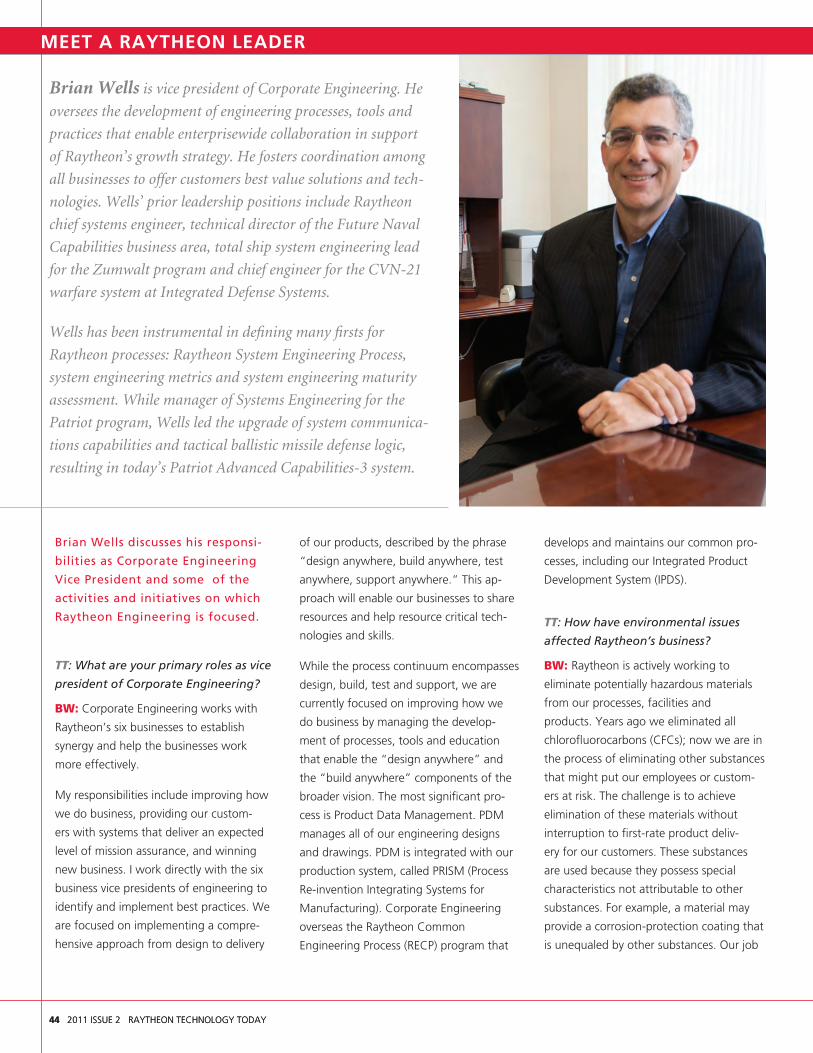
44 2011 ISSUE 2 RAYTHEON TECHNOLOGY TODAY
Brian Wells discusses his responsi-
bilities as Corporate Engineering
Vice President and some of the
activities and initiatives on which
Raytheon Engineering is focused.
TT: What are your primary roles as vice
president of Corporate Engineering?
BW: Corporate Engineering works with
Raytheon’s six businesses to establish
synergy and help the businesses work
more effectively.
My responsibilities include improving how
we do business, providing our custom-
ers with systems that deliver an expected
level of mission assurance, and winning
new business. I work directly with the six
business vice presidents of engineering to
identify and implement best practices. We
are focused on implementing a compre-
hensive approach from design to delivery
of our products, described by the phrase
“design anywhere, build anywhere, test
anywhere, support anywhere.” This ap-
proach will enable our businesses to share
resources and help resource critical tech-
nologies and skills.
While the process continuum encompasses
design, build, test and support, we are
currently focused on improving how we
do business by managing the develop-
ment of processes, tools and education
that enable the “design anywhere” and
the “build anywhere” components of the
broader vision. The most significant pro-
cess is Product Data Management. PDM
manages all of our engineering designs
and drawings. PDM is integrated with our
production system, called PRISM (Process
Re-invention Integrating Systems for
Manufacturing). Corporate Engineering
overseas the Raytheon Common
Engineering Process (RECP) program that
develops and maintains our common pro-
cesses, including our Integrated Product
Development System (IPDS).
TT: How have environmental issues
affected Raytheon’s business?
BW: Raytheon is actively working to
eliminate potentially hazardous materials
from our processes, facilities and
products. Years ago we eliminated all
chlorofluorocarbons (CFCs); now we are in
the process of eliminating other substances
that might put our employees or custom-
ers at risk. The challenge is to achieve
elimination of these materials without
interruption to first-rate product deliv-
ery for our customers. These substances
are used because they possess special
characteristics not attributable to other
substances. For example, a material may
provide a corrosion-protection coating that
is unequaled by other substances. Our job
Feature
Brian Wells is vice president of Corporate Engineering. He
oversees the development of engineering processes, tools and
practices that enable enterprisewide collaboration in support
of Raytheon’s growth strategy. He fosters coordination among
all businesses to offer customers best value solutions and tech-
nologies. Wells’ prior leadership positions include Raytheon
chief systems engineer, technical director of the Future Naval
Capabilities business area, total ship system engineering lead
for the Zumwalt program and chief engineer for the CVN-21
warfare system at Integrated Defense Systems.
Wells has been instrumental in defining many firsts for
Raytheon processes: Raytheon System Engineering Process,
system engineering metrics and system engineering maturity
assessment. While manager of Systems Engineering for the
Patriot program, Wells led the upgrade of system communica-
tions capabilities and tactical ballistic missile defense logic,
resulting in today’s Patriot Advanced Capabilities-3 system.
44 2011 ISSUE 2 RAYTHEON TECHNOLOGY TODAY
MEET A RAYTHEON LEADER

is to find suitable substitutes for these
materials that meet customer require-
ments. I sponsor a committee, composed
of our leading experts, who focus on this
on an ongoing basis
TT: What activities are you currently
pursuing to help improve our
engineering capabilities?
BW: Raytheon has many targeted
programs to develop the engineering
expertise necessary to be competitive and
ensure customer success. Over the past
ten years we have greatly strengthened
our systems engineering and architec-
ture capabilities through the Systems
Engineering technical development pro-
gram (SEtdp) and the Raytheon Certified
Architect Program (RCAP). We have
trained more than 750 systems engineers
through SEtdp and more than 400 archi-
tects through RCAP. We have certified
more than 150 Raytheon architects. Both
programs have been a tremendous success
and have helped to improve our capa-
bilities in critical skill areas. In 2010, we
initiated our new Cyber Security Learning
program to address this critical need and
trained more than 50 engineers.
This year, partnered with Johns Hopkins
University (JHU), we graduated the first
class of Masters of Science in Systems
Engineering (MSSE) students. With greater
than 200 students enrolled in the JHU
MSSE program, we continue to expand
and build a strong cadre of systems
engineers.
The newest initiative aimed at all engi-
neers is the Talent and Career Explorer
(TACE) system. Initially rolled out at Missile
Systems this year, it will extend to our
other businesses within the next year.
TACE provides engineers with a method
of identifying their skills and comparing
these to the requirements for the roles
that interest them. With their skill assess-
ment, engineers can select courses via
LMS (Raytheon’s learning management
system) to close known skill gaps. TACE
also provides managers with a method of
quickly identifying engineers with critical
skills who are needed to support specific
programs. With TACE we can locate
talent across the enterprise and improve
our organizational synergy.
TT: For the past five years you have
led teams who have examined the
U.S. education system to determine
methods for improving science, tech-
nology, engineering and math (STEM)
graduation rates from U.S. universities
and colleges. What was the purpose of
those activities and what are you
currently doing in this area?
BW: Our STEM activities started in 2006
with the goal of identifying the high lever-
age points in the U.S. education system.
Our CEO asked us to determine where
investment by government and industry
would have the most benefit. To answer
this question we had students in the SEtdp
apply systems engineering methods to
the U.S. education system. SEtdp teams
analyzed this complex system as their way
of learning systems engineering processes
and methods. Through their research,
computer modeling activities and systems
engineering activities, we determined that
the highest leverage point is freshman
year of college. Only about 40 percent of
freshman who declare a STEM degree will
graduate with one in six years. This is a
tremendous loss, given that these students
were interested in STEM and were profi-
cient upon university entrance. We also
learned that, for engineering, women are
significantly underrepresented. Only about
20 percent of engineers are women and
only about 33 percent of physical scientists
are women, despite the fact that they are
equally as proficient as men in STEM up
through 12th grade. Additionally, about
20 percent of disadvantaged and minority
high school students, who are proficient
and interested in STEM, do not even
attend college. Based on this data,
Raytheon has strengthened our focus
on attracting women and minorities to
science, technology, engineering and
mathematics.
TT: What other activities are you
involved with that provide mission
assurance to our customers?
BW: One of my areas of concentration is
on programs where there are issues that
affect mission assurance. Engineering
works closely with the Mission Assurance
and Operations organizations. Our sys-
tems must provide our customers with
the capabilities they expect the first time
and every time. To ensure this, especially
on the most challenging and highest risk
programs, I actively participate in program
and technical reviews. These are often the
most challenging engineering problems
where Raytheon employs leading-edge
technology. My job is to connect with the
best technical experts across the enterprise
to address these challenges. We have
tremendous capabilities within our com-
pany, and we perform best when the
right people are quickly assigned. •
RAYTHEON TECHNOLOGY TODAY 2011 ISSUE 2 45

on Technology
46 2011 ISSUE 2 RAYTHEON TECHNOLOGY TODAY
Raytheon’s recent advances in cognitive computing (software/hardware that mim-ics human mental processes of perception, memory, intelligence and consciousness) have shown that computers have the poten-tial to do as well as humans at assimilating and analyzing information. This includes dealing with information across multiple information sources (e.g., newspapers, magazines, Web, chat, television, radio, telephone, recordings) and information types (e.g., hard copy or electronic). These advances have resulted in the development of an artificial cognitive neural framework that uses metacognitive (knowledge about knowing) and metamemory (knowledge about memory) processing concepts simi-lar to those that the human brain uses to process, categorize and link information. Current applications include Integrated System Health Management and Adaptive Learning Systems for command, control, communications, computers, intelligence, surveillance and reconnaissance (C4ISR).
Artificial CognitionTo understand the world we live in, we gather information via our senses and pro-cess that information in ways that enable us to reason about what we perceive. The accuracy of our perception is determined by the accuracy of our information (e.g., credibility, applicability, comprehensiveness, representativeness and context) and how we apply reasoning to that data through the lens of our beliefs and assumptions.
This is also true when information analysts mine diverse information sources for clues and insights. First, the information is col-lected from diverse sources, each with its own context and error source. Because of the diverse error sources and contexts,
ambiguity is introduced into the correla-tion and inference processes applied to the combined information. This ambiguity can make it difficult for information analysts to use such data to find related events and infer likely outcomes. Moreover, an ana-lyst’s personal variables (e.g., health, focus, experience, learning, emotions, beliefs and assumptions) may also affect the analysis process.
To assist the information analyst, Raytheon has developed a processing architecture that employs intelligent information software agents (ISAs) that operate within an artifi-cial cognitive neural framework (ACNF), as shown in Figure 1. ISAs are active, persistent software components that perceive, reason, act and communicate with each other. The ACNF is a hybrid computing architecture that uses genetic learning algorithms, neural networks and fuzzy classification algorithms that allow diverse information sources and
events to be associated and correlated, enabling the ACNF to make observations, process information, make inferences and recommend decisions.
The ACNF uses continuously recombinant neural fiber networks that map complex memory and learning patterns as the ACNF evolves or adapts to its environ-ment. Continuously recombinant neural fiber networks are neural networks whose internal topology adapts as the system learns and evolves. The entire system func-tions and communicates via the ISAs that mimic human capabilities (analysis, reason-ing, learning, and reporting; i.e., cognitive intelligence). These capabilities can process diverse information types and sources and translate them into actionable information within the ACNF framework. Specifically, this cognitive intelligence can answer ques-tions and explain situations.
Cognitive Computing Advances Help Computers Work More Like the Human Brain, Improve Information Gathering
Figure 1. The Artificial Cognitive Neural Framework (ACNF) provides a software environment that allows the computer system to mimic human cognitive processes.
Mediator (ArtificialPrefrontal Cortex)
BroadcastsMemories
FixedInformation
Gathers and ProvidesInformation
Provides Analysis and ThoughtProcesses
Take InOutside
InformationProvides Emotional Context
Provides Contextual Awareness
Create, Modify and Update
CognitivePerceptrons
ArtificialCognition
LearningAlgorithms
NeuralMemories
ArtificialNeuralEmotions
ArtificialConsciousness

RAYTHEON TECHNOLOGY TODAY 2011 ISSUE 2 47
One category of ISAs within the ACNF takes the form of cognitive perceptrons, a type of ISA used to carry cognitive information throughout the ACNF, which can learn from experiences and can be used to predict future states (prognostics). Cognitive per-ceptron ISAs analyze sensor data to detect complex states and diagnose problems. They can interface with other autonomic software agents within the system to form software agent coalitions. They can also reason using domain-specific application objects and can have autonomous be-haviors and goals. The ACNF framework provides memory categories similar to those of human memory systems, includ-ing sensory memories, short-term (working) memories and long-term memories. These memory categories retain not only knowl-edge, but also the contextual, temporal and spatial information relevant to the sensory data and information processed and re-tained by the ACNF processes.
Other types of ISAs furnish the artificial cog-nition and the artificial prefrontal cortex1 (mediator) processes that allow the ACNF to function autonomously (without supervi-sion). These ISAs are autonomous software agents that create, in essence, an informa-tion agent ecosystem, comprehending its external and internal environment and acting on it over time, in pursuit of its own agenda and goals, so as to affect what it comprehends in the future. The three main subsystems within the ACNF are:
• The mediator (the artificial prefrontal cortex), shown in green: This takes infor-mation processed through the artificial cognition processes from the cogni-tive perceptrons, forming coalitions of perceptrons that are used to update the short-term, long-term and episodic memories.
• The memory system, shown in tan: The memory system consists of sensory, short-term and long-term memories. The memory system continually broadcasts the information that is available within the ACNF memories (what the system has learned and “knows”) to the conscious perceptrons that form the cognitive cen-ter of the system.
• The cognitive system, shown in blue: This provides the cognitive, learning, emotion and consciousness structures, which are responsible for the cognitive functionality of perception, conscious-ness, emotions, information processing and other cognitive functions within the ACNF.
Cognitive PerceptronsFour types of cognitive perceptrons operate within the ACNF (Figure 2):
• Thedata steward perceptron generates and maintains the metadata required to find and extract information from hetero-geneous information sources.
• Theadvisor perceptron generates and maintains the topical/subject information required to find information within the memory system relative to the current problem (or topic) being processed.
• Thereasoner perceptron analyzes ques-tions and relevant source information to provide answers to analysts and to develop cognitive rules within the ACNF for future cognitive processes (adapt and evolve the system as it learns).
• Theanalyst perceptron uses inferences (patterns of thinking) to direct question-and-answer generation and to create situational analysis, based on the current and learned information about a current topic, with integrated explanations based on all available information.
ConclusionsOur research has shown that the cogni-tive perceptrons, in combination with the ACNF, provide an architecture, framework, and processes that facilitate cognition, learning, memories and information pro-cessing in an autonomous fashion, similar to human reasoning, and can greatly assist information analysts. Future work includes providing knowledge density (a measure of how much the system knows/has learned about a particular topic/subject) and analyti-cal competency (a measure of the system’s ability to reason or analyze information per-taining to a particular topic/subject).These processes will enable the system to assess its own capabilities and knowledge gaps. •
Dr. James A. Crowder
1In humans, the prefrontal cortex carries out executive functions that provide the ability to differentiate among conflicting thoughts, determine correct actions and de-termine future consequences of current activities. It also provides our metacognitive and metamemory capabilities.
Figure 2. The cognitive perceptron ISAs take in sensory information, analyze it, reason about it and provide feedback (advice) to information analysts about their findings.
Mem
orie
s
ReasonerPerceptron
AdvisorPerceptron
AnalystPerceptronPatterns
LexiconOntology
DataSteward
Perceptron
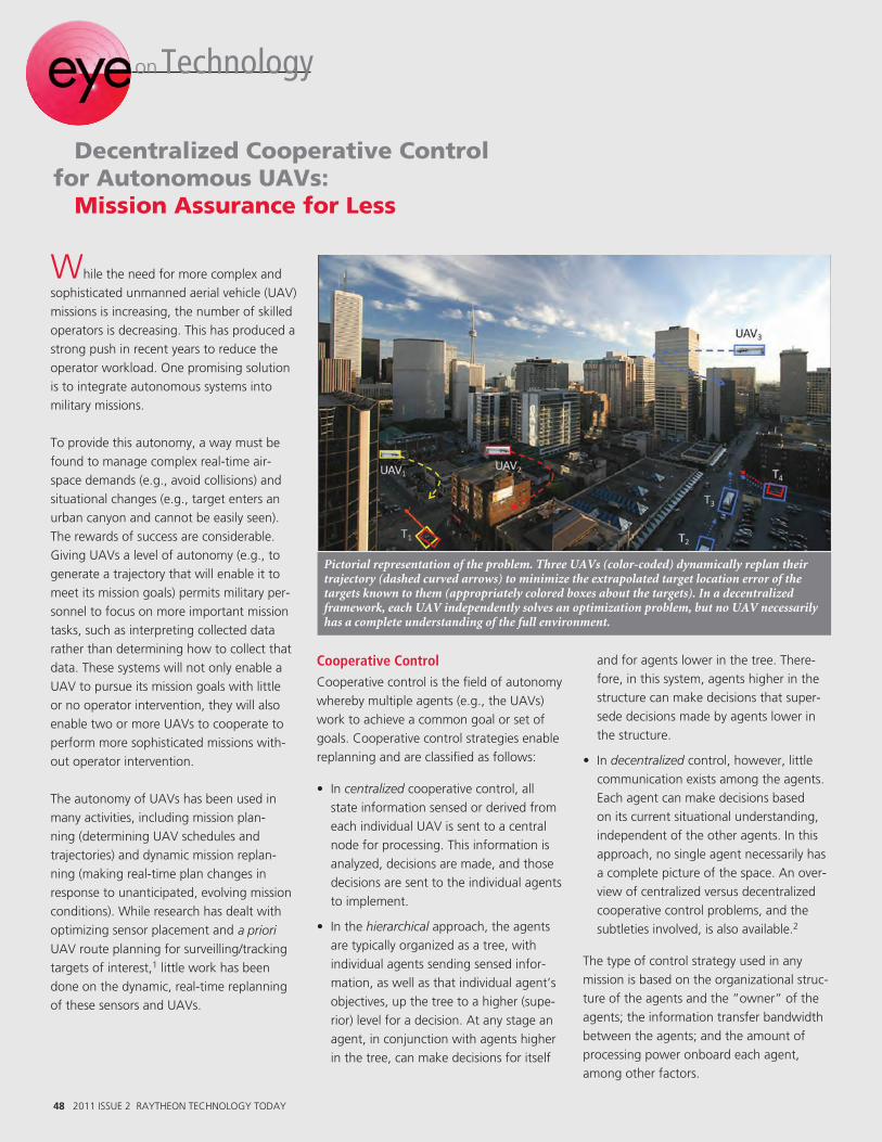
48 2011 ISSUE 2 RAYTHEON TECHNOLOGY TODAY
While the need for more complex and sophisticated unmanned aerial vehicle (UAV) missions is increasing, the number of skilled operators is decreasing. This has produced a strong push in recent years to reduce the operator workload. One promising solution is to integrate autonomous systems into military missions.
To provide this autonomy, a way must be found to manage complex real-time air-space demands (e.g., avoid collisions) and situational changes (e.g., target enters an urban canyon and cannot be easily seen). The rewards of success are considerable. Giving UAVs a level of autonomy (e.g., to generate a trajectory that will enable it to meet its mission goals) permits military per-sonnel to focus on more important mission tasks, such as interpreting collected data rather than determining how to collect that data. These systems will not only enable a UAV to pursue its mission goals with little or no operator intervention, they will also enable two or more UAVs to cooperate to perform more sophisticated missions with-out operator intervention.
The autonomy of UAVs has been used in many activities, including mission plan-ning (determining UAV schedules and trajectories) and dynamic mission replan-ning (making real-time plan changes in response to unanticipated, evolving mission conditions). While research has dealt with optimizing sensor placement and a priori UAV route planning for surveilling/tracking targets of interest,1 little work has been done on the dynamic, real-time replanning of these sensors and UAVs.
Cooperative ControlCooperative control is the field of autonomy whereby multiple agents (e.g., the UAVs) work to achieve a common goal or set of goals. Cooperative control strategies enable replanning and are classified as follows:
• Incentralized cooperative control, all state information sensed or derived from each individual UAV is sent to a central node for processing. This information is analyzed, decisions are made, and those decisions are sent to the individual agents to implement.
• Inthehierarchical approach, the agents are typically organized as a tree, with individual agents sending sensed infor-mation, as well as that individual agent’s objectives, up the tree to a higher (supe-rior) level for a decision. At any stage an agent, in conjunction with agents higher in the tree, can make decisions for itself
and for agents lower in the tree. There-fore, in this system, agents higher in the structure can make decisions that super-sede decisions made by agents lower in the structure.
• Indecentralized control, however, little communication exists among the agents. Each agent can make decisions based on its current situational understanding, independent of the other agents. In this approach, no single agent necessarily has a complete picture of the space. An over-view of centralized versus decentralized cooperative control problems, and the subtleties involved, is also available.2
The type of control strategy used in any mission is based on the organizational struc-ture of the agents and the ”owner” of the agents; the information transfer bandwidth between the agents; and the amount of processing power onboard each agent, among other factors.
Pictorial representation of the problem. Three UAVs (color-coded) dynamically replan their trajectory (dashed curved arrows) to minimize the extrapolated target location error of the targets known to them (appropriately colored boxes about the targets). In a decentralized framework, each UAV independently solves an optimization problem, but no UAV necessarily has a complete understanding of the full environment.
on Technology
Decentralized Cooperative Control for Autonomous UAVs: Mission Assurance for Less

RAYTHEON TECHNOLOGY TODAY 2011 ISSUE 2 49
Although much research exists on central-ized control, little exists on the problems posed by decentralized control. In response to this, we developed a decentralized coop-erative control approach for UAVs tasked to track moving ground targets through an urban environment.3 In this approach, each UAV flies below the height of the buildings and must balance three types of constraints:
• CommunicatewithotherUAVs(tosharerelative positions and sensed information on targets).
• Maintainlineofsighttothetarget(tak-ing into account sensor limitations and target obfuscation by buildings).
• AvoidacollisionwithotherdynamicUAVs and buildings.
To accomplish these tasks, each UAV imple-ments its own dynamic feedback loop, solving a highly nonlinear receding-horizon trajectory optimization problem.
The figure depicts this problem at a given snapshot in time. The pictured scenario con-sists of three UAVs and four targets in an urban environment. The three UAVs all have a current, planned trajectory moving for-ward in time (dashed curved arrows). Each UAV’s estimate of the targets known to it is represented by the appropriately colored boxes about the targets. The dotted arrows coming from the colored boxes represent the extrapolated trajectory of the targets, from the UAV’s perspective. Each UAV must consider the potential movements of the targets, as well as the potential move-ments of the other UAVs, and dynamically replan its trajectory to jointly minimize the anticipated target location error of all of the targets known to that UAV.
Solution ApproachTo efficiently solve this trajectory optimi-zation problem, we use a relatively new approximation routine (i.e., heuristic), the Continuous Greedy Adaptive Search Procedure (C-GRASP).4 This is a multi-start
local search procedure with each iteration consisting of two phases: a construction phase and a local search phase. In the construction phase, interactions between greediness (locally good) and randomization (arbitrary movement) generate a diverse set of high-quality solutions. The local search phase improves upon the solutions found in the construction phase. The best solu-tion over all of the multi-start iterations is adopted.
A solution for a given UAV is its flight path, as well as the predicted paths of the UAV’s neighbors. Note that the UAV does not communicate its solution to its neighbors because each neighbor is also solving its own problem and potentially has additional information for use. At each time-step, each UAV solves a problem for itself and its neighbors based on its own knowledge. Each UAV then implements its own solution.
Experimental ResultsThe formulation and heuristic described above were exercised by varying the num-ber of available UAVs in a scenario having six targets operating in an urban setting. These ground targets were simulated with minimum and maximum speeds of 0 and 30 miles per hour, respectively. Eight buildings, each 150 meters high, comprised the urban setting. The study involved having one to five UAVs in the scenario autonomously track the moving ground targets.
Results from the study5 indicate that the uncertainty in target location decreases as UAVs are added to the scenario. This is to be expected. What was not expected was the diminished rate of return in the target location uncertainty as the number of UAVs increases. This was especially apparent once all of the targets were discovered in the sce-nario. When detailed plots were analyzed, it was clear to see that our decentralized cooperative control approach exploits the availability of multiple UAVs for cooperative tracking by defining flight trajectories that result in improved track accuracy of the targets in the scenario.
ConclusionsAutonomous systems will play an increas-ing role in tasks that require split-second decision making. As our experimentation on cooperative tracking as a function of the number of UAVs in the scenario shows, this approach does indeed produce an ac-curate representation of targets in an urban setting. Future research will investigate heterogeneous UAV sensor capabilities and how they affect cooperative tracking perfor-mance. This research shows that distributed platforms and sensors lacking continuous net-centric communication connectivity could work together to aid in data fusion. Whether the mission is target tracking or reconnaissance and surveillance, an ana-lytically rigorous process for managing the sensing platforms is critical to success.
The mathematical model is extensible both in the domain and to the objectives of dif-ferent applications. For example, a very similar formulation could be used for unat-tended sensors, manned vehicles and even virtual agents working in cyberspace. This problem formulation and methodology can be applied to all modes of process refine-ment as an integral part of the data fusion process. •
Dr. Michael J. Hirsch
1G. Gu, P.R. Chandler, C.J. Schumacher, A. Sparks, and M. Pachter, “Optimal cooperative sensing using a team of UAVs,” IEEE Transactions on Aerospace and Electronic Systems, vol. 42, no.4, 1446–1458, 2006; J. Kim and J. L. Crassidis, “UAV path planning for maximum visibility of ground targets in an urban area,” in Proceedings of the 13th International Conference on Information Fusion, 2010.2P. Chandler, M. Pachter, “Challenges in UAV Cooperative Decision and Control,” T. Shima and S. Rasmussen, Eds. SIAM, 2009, 15–36.3M.J. Hirsch, H. Ortiz-Pena, and C. Eck, “Cooperative tracking of multiple targets by a team of autonomous UAVs,” International Journal of Operations Research and Information Systems, vol. 3, no.1, 2012. 4M.J. Hirsch, P.M. Pardalos, and M.G.C. Resende, “Speeding up Continuous GRASP,” European Journal of Operational Research, 205(3), 507–521, 2010.5M.J. Hirsch, H. Ortiz-Pena, and M. Sudit, “Decentralized Cooperative Urban Tracking of Multiple Ground Targets by a Team of Autonomous UAVs,” Proc. of the 14th International Conference on Information Fusion, 1196–1202, Chicago, Ill. July 2011.

50 2011 ISSUE 2 RAYTHEON TECHNOLOGY TODAY
on Technology
50 2011 ISSUE 2 RAYTHEON TECHNOLOGY TODAY
Existing cyber defense methods, includ-ing manual analysis, firewalls and anti-virus products, are reactive by design and must wait for attacks to occur before they can try to respond. Our adversary, the advanced persistent threat (APT),1 actively leverages numerous tools, from covert information gathering agents to cyber attack platforms, against these defenses. Moreover, well-funded, military-style hacker communities are working around the clock to sabotage and steal from our most sensitive networks.
Defense industry assets, including network servers and employees, have been targeted by the APT for several years, and hard-to-detect, well-organized attacks often flourish unnoticed over long periods of time. To combat the APT’s ever-changing and increas-ingly sophisticated attacks, a flexible, active defense must be developed that will stop the first instance of an emerging attack.
To answer this need, the Man in the Mirror (MiM) algorithms were conceived to provide both preemptive and real-time attack pro-tection. MiM detects and deters malware packages by applying advanced behavioral analytics. Whereas firewalls try to defend the perimeter at network ports that must remain open, MiM adds another layer of protection by guarding the individual user “inside the walls.” Figure 1 depicts how MiM integrates with existing security layers.
MiM achieves this protection by comparing user interaction with associated application and network activity for threat indicators, acting definitively in response. And, while a user must always stay vigilant in regard to security, an additional benefit of MiM’s pro-active defense strategy is that it relieves the user of much of the safety burden.
Figure 2 highlights a few of MiM’s benefits.
• MiMislikehavingacomputeremer-gency response team malware expert protecting every desktop, but at dramati-cally lowered costs.
• MiM’son-the-desktopprotectionrespondsto attacks immediately, significantly reduc-ing the chances for data exfiltration.
• MiM’sreal-timedetection capa-bilities offer con-tinual protection against zero-day threats, minimiz-ing the attack window available to malware authors.
MiM develop-ment focused on creating pragmatic behavioral methods that could be im-mediately tested and observed in functional prototypes. Subjecting MiM prototypes to real-world malware threats provided sink-or-swim tuning opportunities that inspired sophisticated detection and deterrence algorithms. These novel algorithms evalu-ate threats at their most observable points, using behavioral tells.2 It is these tells that provide a streamlined approach which, with-out specific knowledge of particular threats, can successfully detect over 70 percent of real-world malware, regardless of how the threats are introduced to the system (whether USB, email or website). In fact, one of MiM’s unique features is that it has no need for a threat database. Instead, behav-ioral algorithms use straightforward rules to determine threat likelihood in real time.
MiM, operating much like a computer secu-rity expert, reacts based on the context of the scenario.
MiM is currently undergoing productization to prepare it for deployment on networks run-ning the Raytheon SureView™ infrastructure. SureView is a proactive, information-pro-tection solution, monitoring behavior on computer endpoints for policy violations and high-risk activity. It was the use of SureView’s extensibility and existing footprint that allowed the MiM team to focus on the de-velopment of core behavioral algorithms and rapidly deliver positive results. These benefits are summarized in Table 1.
MiM offers a comprehensive, active defense solution against both today’s battles and tomorrow's threats. • Jim Bostick
The Man in the Mirror™ System Uses Behavioral Analytics to Actively Defend Against Cyber Attacks
Figure 2. MiM compared with manual detection and response methods in four areas: operating costs, response time, detection confidence, and likelihood of real-time detection and deterrence of zero-day threats. Although MiM’s overall detec-tion has a slightly lower level of confidence, it costs less, detects threats more quickly and has a higher likelihood of stopping zero-day threats.
1A group, such as a foreign nation-state government, with both the capability and the intent to persistently and effectively target a specific entity.2A tell, as applied to MiM, is a subtle but detectable trait that reveals intent.
Figure 1. MiM enhances layered security by protecting users’ desktops.
End UserReduces the burden of security on the user (e.g., even though users often open every email they receive, MiM lessens the negative impacts of instinctive compliance).
Does not interfere with user productivity. MiM protects without bothering the user with distracting popups or questions to answer.
Detects and stops malware processes and associated network activity, allowing users to maintain full network connectivity, even during an attack.
Provides active defense with only negligible CPU impact.
EnterpriseStops existing and future malware threats due to protection based on generalized behavioral descrip-tions and responses.
Enables sophisticated threat management capabilities for enterprise-level information security operations by incorporating human inputs (e.g., current THREATCON level and behavioral descriptions of new threats).
Easy to deploy and update using SureView’s exist-ing infrastructure.
MiM’s threat detection leverages the local process-ing overhead of the user it protects, eliminating the need for additional servers.
Table 1. MiM Benefits for the End User and the Enterprise
10k Days Minutes
Man in the MirrorManual detection and response
Seconds100k 1M
High
Med
ium
Low
High
Med
ium
Low
Hig
k Minutes
Man
Second100k
ghM
ediu
mum
Days1M
mLo
wM
ediu
mLo
w
y
w
Likelihood of real-time detection anddeterrence of zero-day threats
Detectionconfidence
Operating costs ($/yr) Response time
MiM
SureView
Anti-virus
RShield
Firewall solutions

RAYTHEON TECHNOLOGY TODAY 2011 ISSUE 2 51
People
First Raytheon Master of Science in Systems Engineering Class Graduates from Johns Hopkins
Beginning January 2009, Raytheon
Engineering partnered with Johns
Hopkins University to offer a new onsite
certificate and Master of Science in
Systems Engineering (MSSE) degree
program. Its purpose is to assist students
in developing the systems engineering
knowledge, skills and tools necessary to
successfully lead the planning, development
and engineering of large, complex systems.
The first Raytheon-JHU MSSE class of
22 graduates celebrated at a June 10, 2010
ceremony held at the Pima Air and Space
Museum in Tucson, Ariz.
Congratulations to all the MSSE graduates:
Thomas Betts Justin Jochum
Giselle Bonilla-Ortiz Wilmer Justiniano
Jeffrey Brunet Kenneth Leong
Arnaldo Colon Shun Lo
Natalie Davila-Rendon Stanley Pebley, Jr.
Aaron Ellis Thomas Reinert
Jaime Erickson Luis Rivera
Nathanial Ernst Jarret Sample
Richard Espino Mark Szlemko
Mark Fox Luicina Terrien
Allison Henrickson Michael Wethington
The Raytheon–JHU MSSE program
currently has more than 200 Raytheon
employees participating from across the
company. The initial five courses in the
degree program are standard across the
company, ensuring common language,
practices and processes. The remaining
five courses are customized to address
business and location-specific technologies
and applications.
Giselle Bonilla-Ortiz has been with Raytheon for five years. She supported the devel-opment, testing and performance evaluation of fea-ture extraction and fusion algorithms
for various missile programs. Currently, she works as a software engineer and RF analyst. Her responsibilities include the design of soft-ware algorithms and their implementation into missile tactical software, and the testing and performance data analysis of these algorithms.
Bonilla-Ortiz recalled, “Even as I worked towards my bachelor’s in computer engineer-ing at the University of Puerto Rico, Mayagüez Campus, I was drawn to the methodologies and processes used to produce technically effective software products, and to software engineering’s systematic principles to create high-quality, affordable and maintainable prod-ucts quickly and efficiently. Later I learned that many of these same principles can be applied to complex systems, beyond the boundaries of software.” For Bonilla-Ortiz, the JHU systems engineering curriculum provided the skills nec-essary to effectively interface across the systems’ components and to the stakeholders involved.
According to Bonilla-Ortiz, “A systemwide perspective is beneficial regardless of an indi-vidual’s role in a program. Becoming familiar with the entire system is crucial for effective communication across groups. I have also made it a priority to understand the interfaces between sub-products and the performance implications my software designs impose on the system. The significance of having a systems viewpoint has also given me the initiative to ask questions, thereby acquiring more in-depth knowledge, furthering my comprehension of how each algorithm affects a system’s performance.”
Bonilla-Ortiz found that the JHU program provided greater insight into how Raytheon conducts business throughout all phases of a program lifecycle. Also, by learning about the tools and processes for engineering large, com-plex systems, it has provided a solid foundation to build a career and undertake lifelong learn-ing, critical to the role of systems engineers.
Jarret Sample has worked 12 years for Raytheon as an electrical design engineer with an emphasis on telemetry subsystem devel-opment. During
this time, he supported a number of pro-grams. He’s had the opportunity to engage in all phases of a product life cycle, spanning concept development, requirements genera-tion, product development, integration and testing, production, fielding and training the customer in the use of the product.
When asked about his motivation for pursuing a career in systems engineering, Sample remarked, “Although I thoroughly enjoyed my time working with subsystems, I realized my true interest lies in the system as a whole. My natural curiosity about the sys-tem and the many engineering disciplines required to develop, produce and maintain it influenced my decision to become a sys-tems engineer.”
Speaking to the value of the JHU program, Sample further explained, “I believe a great systems engineer is able to strike a balance between having broad technical knowledge, spanning the various engineering disci-plines, and the ability to dive deeper into specific focus areas as required. The JHU program offered me the ability to greatly expand my knowledge of the systems engi-neering discipline and provided me with a solid foundation for success. By completing in-depth coursework that addressed the various phases of the engineering life cycle of a system, I have developed a key set of tools that will help me excel as a systems engineer.”
Sample also noted that an important benefit of the JHU program is the opportu-nity to interact and learn from some of the top engineering minds in Raytheon. The Raytheon instructors augmented lessons in the principles of systems engineering, by providing key insight drawn from their personal experiences.
Graduate Profile Graduate Profile

52 2011 ISSUE 2 RAYTHEON TECHNOLOGY TODAY
Events
Energy, Environment, Defense and Security (E2DS) Conference 2011
Held in Washington, D.C., May 3-4, the E2DS conference brought together technology leaders in the defense indus-try, domestic and international representatives from the
government and defense communities, and university research-ers to discuss solutions to global environmental challenges. This was the second conference; the first was held in London in 2009. Raytheon was an industry sponsor and participant.
Addressing the complexity and far-reaching impacts of regional and world environmental issues we face today requires the coordi-nated efforts of academia to understand the science, governments to establish and carry out policy, and industry to help implement solutions. The defense industry has a well established history of working closely with these partners to solve difficult, multi-faceted problems. As demonstrated in this issue of Technology Today, and the previous issue on energy, a significant part of Raytheon’s heritage is working hand-in-hand with universities, governments and industry partners to understand our environment, address our energy needs and mitigate the detrimental effects of weather, climate change and environmental pollution on our society. We provide unique capabilities as a technology company, as a systems integrator and as a problem solver.
At the conference, Raytheon Vice President of Engineering, Technology and Mission Assurance Mark E. Russell participated in a panel with other de-fense company technology leaders to discuss the abil-ity of the defense sector to provide solutions to global environmental problems. He pointed to Raytheon’s leadership roles on the System for Vigilance of the Amazon (SIVAM), Collaborative Adaptive Sensing of the Atmosphere (CASA), the Ocean Observatories Initiative (OOI), the Joint Polar Satellite System (JPSS), and the development of scal-able and renewable energy solutions as examples of significant Raytheon contributions that reach beyond the realm of defense.
Bruce Snider, director of Technology for Raytheon’s Network Centric Systems, and Diane Mahoney, program manager for Raytheon’s Ocean Observatories Initiative support to the Woods Hole Oceanographic Institution, participated on a panel addressing global environmental needs at a system-of-systems level.
Snider presented Raytheon’s capabilities and experience in the design and operation of large complex systems and associated data man-agement. He discussed how Raytheon’s work addresses cyber security
for the national power grid and the development of renew-able energy solutions for microgrids. Raytheon collaborates with the University of Arizona in managing the biosphere. We have had an active decade-long contract with the National Science Foundation to provide technical and environmental oversight and training at three year-round U.S. locations, numerous field camps, and on two research vessels in the Antarctic regions. Raytheon has also developed a systems architecture for the Global Earth Observatories System-of-Systems (GEOSS).
Diane Mahoney teamed with Woods Hole to discuss the highly collaborative develop-ment of a vast system of ocean-monitoring sensors for understanding its complex eco-system. As Mahoney explained, 72 percent of the earth is covered by ocean, where the planet stores heat, CO2 and natural resources. The purpose of the NSF-funded project is to understand the ocean as a sys-tem. Started in 2009, the OOI project will take five years to construct and is being designed to collect and process data for 25 years. Many partners are involved in the project. Woods Hole is a key implementing organization and Raytheon is providing select engineering services.
All participants acknowledge the immense challenges ahead. In his remarks, Nick Cook, the conference organizer, noted that since the first meeting in 2009, the discussion had matured from a debate over the extent of the problem to a debate on how best to solve it. •
Engaging the Aerospace, Defense and Security Sectors in Energy, Environment and Counter-Climate Change Markets

RAYTHEON TECHNOLOGY TODAY 2011 ISSUE 2 53
Events
2010 Raytheon Six Sigma™ President’s and CEO Awards
On June 7, 2011, the achievements of Raytheon Six
Sigma teams across the enterprise were recognized
for providing substantial and measurable results
and impact for Raytheon’s businesses, customers and sup-
pliers. Raytheon leaders, Raytheon Six Sigma Experts and
honorees gathered for the event at the Fairmont Copley
Plaza Hotel in Boston, Mass.
Fourteen teams were selected for the Raytheon Six Sigma
President’s Award, presented to the top project or projects
within a business for overall excellence. Seven teams were
honored with the prestigious Raytheon Six Sigma CEO
Award, presented for projects selected as best-in-class by
Raytheon Chairman and CEO, William H. Swanson. The
selection criteria included project value to the customer,
measurable business results and potential for future
application across the enterprise.
Vertical banners illustrating the teams’ achievements
were displayed during the event reception. Swanson and
Raytheon leaders toured the gallery of presentations and
discussed the project highlights with the team members.
Raytheon Six Sigma – A Decade of Transformation
Swanson delivered the keynote remarks reflecting on
Raytheon Six Sigma’s contributions to the company’s suc-
cess. He noted that since Raytheon Six Sigma was founded
more than 10 years ago, it has been indispensable in
transforming the company, starting with a mindset that
conveyed, “Do what’s right by our customers.”
Mark E. Russell, Raytheon vice president of Engineering,
Technology and Mission Assurance opened the event and
congratulated the award winners for making fundamen-
tal contributions to the future of Raytheon. “Our award
winners have made a commitment, both individual and
collective, to get the job done right,” said Russell. Master
of ceremonies for the evening was John Bergeron, director
of Raytheon Six Sigma, who is leading the program's enter-
prisewide revitalization. It was a great evening highlighted
by successes across the enterprise. •
2010 Raytheon Six Sigma Award Winners
Corporate Development Acquisition Integration Process Team - CEO AwardLynn Bailey, Paul Clemente, Anthony Delaporta, Daniel Gilmore, Nathaniel Jensen
Corporate ISS Staffing TeamPaul Clegg, James Cronin, Susan McCarthy, Carlos Pelayo
IDS Consolidated Contractor Logistics Support Operational Availability TeamNicholas Depalo, Gail DiGangi, Robert Enzmann, Jeffrey Mollica, Craig Walker
IDS DFSS Ceradyne Supplier Project Team - CEO AwardBrian Foley, Howard Henderson, Jean Imholt, Steven Wakefield, Bryan Wells
IIS Earned Value Lite TeamBrian Bevan, Clare Fitzgerald, Terry Godwin, Mark Shirey, Mark Thorwart
IIS Joint Polar Satellite System Common Ground System Win Team - CEO AwardDarla Duval, Regina Gradishar, Jeffrey McCall,
Tamara Nichelson, William Sullivan
MS Mald Airframe Process Improvement TeamDavid Blanchard, Stephen Bliss, Tyler William Davis, Juliette Haggh,
Charles Lyman, Dan Reller
MS Small Diameter Bomb II Affordability Team - CEO AwardJohn Bloom, Juliette Haggh, Jack Mallgren, Timothy Owensby,
Thomas Russo, John Whiteside
NCS Affordable Competitive Solutions — NCS Flexcareers Team - CEO AwardDarrel Andrews, Aimee Benfield, Peter Coroneos, Donna Holmes, Arlene Lamsa
NCS Zumwalt Excomms Critical Customer Delivery Challenge TeamSteven Hess, James Panagopoulos, Jerold Platt, Wayne Varteresian, Staci Williams
RTSC F/A-18 Radar Repair Turnaround Time Improvement Team - CEO AwardRex Beach, James Dellarocco, John McAllen Jr., Jonathan Phelps,
Diana Tracy, Darren Webb
RTSC Microwave Repair Cycle Time Reduction TeamHumberto Carrasco, Manuel Leos, Joyce Napier, Philip Schneider
SAS APG-79 Capacity and Velocity Improvement Team - CEO AwardKaren Giraudo, David Hotaling, Jerry Keith, Howard Kwan, Denise Meredith
SAS F-15E Radar Modernization Program Critical Chain Culture TeamSherry Barone, Forest Henderson III, Kenneth Hitt, Gary Miller,
Thomas Pulte, Doreen Sasaki
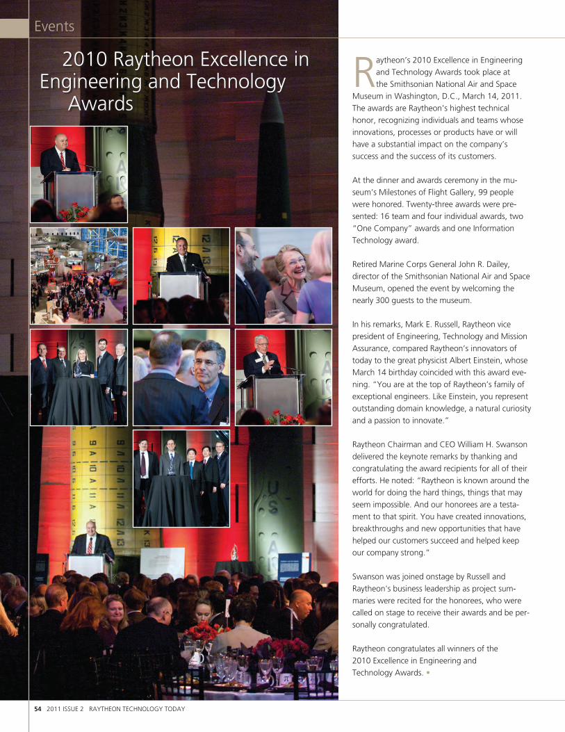
54 2011 ISSUE 2 RAYTHEON TECHNOLOGY TODAY
Events
2010 Raytheon Excellence in Engineering and Technology Awards
Raytheon’s 2010 Excellence in Engineering and Technology Awards took place at the Smithsonian National Air and Space
Museum in Washington, D.C., March 14, 2011. The awards are Raytheon’s highest technical honor, recognizing individuals and teams whose innovations, processes or products have or will have a substantial impact on the company’s success and the success of its customers.
At the dinner and awards ceremony in the mu-seum’s Milestones of Flight Gallery, 99 people were honored. Twenty-three awards were pre-sented: 16 team and four individual awards, two “One Company” awards and one Information Technology award.
Retired Marine Corps General John R. Dailey, director of the Smithsonian National Air and Space Museum, opened the event by welcoming the nearly 300 guests to the museum.
In his remarks, Mark E. Russell, Raytheon vice president of Engineering, Technology and Mission Assurance, compared Raytheon’s innovators of today to the great physicist Albert Einstein, whose March 14 birthday coincided with this award eve-ning. “You are at the top of Raytheon’s family of exceptional engineers. Like Einstein, you represent outstanding domain knowledge, a natural curiosity and a passion to innovate.”
Raytheon Chairman and CEO William H. Swanson delivered the keynote remarks by thanking and congratulating the award recipients for all of their efforts. He noted: “Raytheon is known around the world for doing the hard things, things that may seem impossible. And our honorees are a testa-ment to that spirit. You have created innovations, breakthroughs and new opportunities that have helped our customers succeed and helped keep our company strong.”
Swanson was joined onstage by Russell and Raytheon's business leadership as project sum-maries were recited for the honorees, who were called on stage to receive their awards and be per-sonally congratulated.
Raytheon congratulates all winners of the 2010 Excellence in Engineering and Technology Awards. •

RAYTHEON TECHNOLOGY TODAY 2011 ISSUE 2 55
Events
ONE COMPANY AWARDSMALD–J Block II Mid-Band GaN Amplifier Project TeamTyler William Davis (MS), Elizabeth French (SAS), George Hobbs (SAS), Steven Kromer (MS), Robert Leoni (IDS), Erik Patterson (MS), Allen Hubert Trac (SAS)For creating a gallium nitride MMIC amplifier design which provides a substantial increase in jammer effectiveness in a small, low-cost package.
W-Band Solid State Module TeamAndrew Brown (MS), James Chen (IDS), Darin Gritters (MS), Thomas Hanft (SAS), Kiuchul Hwang (IDS), Patrick Kocurek (SAS), Michael Sotelo (MS) For developing and producing a state-of-the-art high-power W-band module that was used to demonstrate an amplifier for a Joint Non-Lethal Weapons Directorate directed energy array.
INTEGRATED DEFENSE SYSTEMSIndividual AwardJohn ShortFor successfully leading a team of more than 200 engineers supporting the specifi-cation and integration of Air Warfare Destroyer subsystems through the Combat System critical design review.
Air Missile Defense Radar TeamJim Barry, Mike Meservey, William Kennedy, Michael Yeomans, Leon GreenFor developing an innovative, fully compliant radar design in 18 months with new technologies including gallium nitride T/R modules, distributed digital receiver/ex-citers, fully scalable electrical/mechanical design and adaptive digital beamforming.
Space Fence Prototype Demonstration TeamPatrick Makridakis, Peter Maloney, Bruce Myers, Jack Schuss, Thomas SikinaFor developing and demonstrating an affordable, low-risk solution for the Raytheon Space Fence radar design.
X-Band Radar Spiral 1 Debris Mitigation TeamFrancis Joyner, Jason Murphy, Harry G Smith, Benjamin Travisano, Nora TgavalekosFor leading the design, development and verification activity to incorporate new, state-of-the-art, fuel debris mitigation capabilities into the X-band radar system.
INTELLIGENCE & INFORMATION SYSTEMS Green Thunder TeamMike Hanavan, Tony Perry, Rick Poole, Robert Stell, John Terry For developing a complex system architecture for laptops and smartphones that gives soldiers, who are directing operations in the field, access to real-time imagery and signals intelligence data from national systems.
MAJIIC Coalition Data Broker TeamAndrew Askey, Patrick Daulton, Ethan Knepp, Robert Senator, Donald Smith For automating a manual search process for requesting information among coalition partners, making millions of records available to analysts and enabling more accurate decisions to be made in a timely manner.
MISSILE SYSTEMS Individual AwardRobert WickliffeFor leading the Joint Air-to-Ground Missile program to a perfect missile flight test record (six for six).
Joint Air-to-Ground Missile System Software Development Team James Cook, Jonathan Johansen, Lukas Kunz, Lee Miller, Joshua Whorf For successfully developing the operational flight software, seeker algorithms and integrated flight simulations, enabling the program to intercept targets with each mode of its uncooled tri-mode seeker.
Laser Coudé Path TeamCliff Andressen, Ernie Fasse, Rick Koehler, Dave Markason, Bob Rinker For developing active coudé path auto-alignment stabilization that reduces system angular errors by three orders of magnitude and optical decentering errors by a factor of twenty.
Submarine Over the Horizon Organic Capability TeamWilliam Blind, David Bossert, Jeffrey Zerbe For developing the concept and executing the first ever launch, transition-to-flight and control of an unmanned aircraft system from a submerged submarine.
NETWORK CENTRIC SYSTEMS Individual AwardBruce McIntireFor resolving performance and fit issues during system integration for the Florida Turnpike Highway Management System, while processing more than 2.5 million transactions per day and containing approximately 3.6 million rows of data.
Helicopter Alert and Threat Termination Acoustic Rapid Insertion Team Cola Atkinson, James Barger, Daniel Cruthirds, Chris Remer, Scott RitterFor taking a DARPA prototype helicopter small-arms, self-protection system to a flight-certified, deployed system in under 12 months.
Joint Precision Approach and Landing Systems (JPALS) Guidance Algorithm TeamPat Buckner, Rob Fries, Steve Peck, Howard Wan, Shuwu WuFor completing detailed design and validation of the central core of algorithms for the highly variable and restrictive constraints of U.S. Navy ship installation in
10 months, and maintaining the program’s critical path.
NMT Development Test/Operational Assessment Execution Team Peter Eisemann, Richard Foley, Clark Hockenbury, William Pacheco, John Shea, Jr.For confirming more than 1,100 requirements leading to delivery and installation of five Navy Multiband Terminals into operational naval platforms, bringing the new Advanced Extremely High Frequency satellite capability to the fleet.
RAYTHEON TECHNICAL SERVICES COMPANY MultiPurpose Bomb Rack TeamRobert Bailey, Adam Coker, Gregory Deininger, Brian Kavalar, Justin RayFor successfully applying pneumatic technology to offer our customers a superior high ejection velocity weapon release capability for the F/A-18 aircraft while eliminating safety hazards associated with pyrotechnic devices.
RAYTHEON UK Battery Monitor Development TeamLes Allen, Ray Blane, Richard Brown, Scott Dinning, Stewart Ritchie For developing a model for the chemical and temperature effects on battery operation while using a non-intrusive method to accurately measure battery current from milliamps to more than 1,000 amps.
SPACE AND AIRBORNE SYSTEMS Individual AwardEdmond Griffin IIFor his effort on the JLENS SuR program — developing a system that provides long-endurance, wide-area, over-the-horizon detection and tracking capabilities required
to defeat the proliferating cruise-missile threat.
Contango TeamLinda Cunningham, Gary De Mas,Wayne Gardner, Lori Tonder, Paul VawterFor demonstrating engineering excellence in their development efforts that led to
successful attainment of program milestones, yielding an extraordinary customer solution.
Raytheon Advanced Combat Radar TeamJames Conway, Kurt Haidl, Samuel Haslam, Michael McCann, Harold Rounds For the design and development of a form, fit, function, drop-in, exportable Active Electronically Scanned Array radar for the F-16 and early model F/A-18 aircraft.
Seismic and Acoustic Vibration Imaging TeamMaurice Halmos, Matthew Klotz, Victor Leyva, Philip Shimon, Donald Wissuchek For developing a technology demonstrator using Laser Doppler Vibrometry to detect land mines, tunnels, and improvised explosive devices via acoustic and seismic excitation and Doppler measurement of ground surface vibrations.
INFORMATION TECHNOLOGY Structured and Semi-Structured Data Analysis and Correlation TeamNicholas Barrett, Christopher Markley, Josh PyleFor developing a flexible method to synthesize 120 information sources (budget documents, briefs, news articles, request for proposals, reports, etc.) and formulating a sophisticated algorithm to deliver contextually relevant articles and documents directly to the user.
2010 Raytheon Excellence in Engineering and Technology Award Winners

56 2011 ISSUE 2 RAYTHEON TECHNOLOGY TODAY
Events
The Boston Harbor Hotel at historic Rowes Wharf, overlooking Boston’s sunlit harbor, served as a dramatic setting for the 2010
Excellence in Operations and Quality (EiOQ) Awards event on May 20.
One of Raytheon’s highest honors, the EiOQ awards recognize those who demonstrate the pursuit of excellence, dedicated leadership and a commitment to customers by providing the best solutions.
All six businesses were represented. Of the 19 teams, nine were recognized for Accelerating Knowledge Transfer — leveraging knowledge and lessons learned across the enterprise; and two teams were recognized for Energy Conservation.
Mark E. Russell, Raytheon vice president of Engineering, Technology and Mission Assurance, acknowledged 94 award recipients for their achievements. Each recipient contributed to Raytheon’s growth by improving processes, reinforcing the Operations and Performance Excellence culture and, ultimately, ensuring customer satisfaction.
“Tonight’s honorees have demonstrated leadership by solving the tough problems,” said Russell. “They have persisted and addressed the challenges, supporting Raytheon’s mission to ensure customer success.”
The winning teams were joined by their guests, members of the Engineering, Technology and Mission Assurance leadership team, and the business vice presidents for Operations and Mission Assurance.
We recognize this year’s awardees for achieving this honor. Thank you for your outstanding contributions. •
2010 Excellence in Operations and Quality Awards

RAYTHEON TECHNOLOGY TODAY 2011 ISSUE 2 57
Events
ONE COMPANYRaytheon Lessons Learned Solution (RLLS) Team Accelerating Knowledge Transfer AwardMary Carrell (SAS), Steven Clark (IDS), Alan Exley (IDS), Joshua Medor (IDS), Ann Morrison (MS) Created the RLLS — a single, enterprisewide lessons learned system that enables employees and functions in all businesses to share lessons.
INTEGRATED DEFENSE SYSTEMSIndustry Week’s Best Plant Award Application Team Accelerating Knowledge Transfer AwardElizabeth Bowers, Todd Fournier, David Macary, Joseph Shepard, Felicia Thomas The Integrated Air Defense Center was selected as one of only ten facilities to receive “Industry Week’s” Best Plant Award for 2010.Supplier Transparency TeamAccelerating Knowledge Transfer AwardTorrey Cady, Frank Francione Jr., Michelle Hudson, Rosemary McGovern, Mark Salmonsen Connected customers, employees and supplier partners to improve operational excellence across the supplier base resulting in a 42 percent reduction in red rated suppliers, from 28 to 16.
INTELLIGENCE AND INFORMATION SYSTEMSDulles Transition Team Energy Conservation AwardBrian Burns, Carlos Hall, Margaret Mayhugh, Robert O’Connor, John Steele Successfully executed the consolidation of IIS facilities from Falls Church, Reston, and Herndon, Va., into one new campus in Dulles, Va.Global Hawk Platinum TeamJames Bowyer, Dennis Cunningham, Michael Logan, Robert Poole, Charles SwanickAchieved a defect escape rate of less than one-half percent for eight consecutive quarters enabling Raytheon Falls Church to be recognized by their customer as a Platinum Level supplier.Predictive Execution Improvement TeamJames Kiley, Margie Leopold, Melvin Otts Jr., Peter Petohazy, Mark TurnerDeployed advanced predictive tools which significantly improved program performance and secured customer confidence.
MISSILE SYSTEMSFactory Modernization TeamAccelerating Knowledge Transfer AwardKarol Ginorio, Hirath Ghori, Michael O’Haver, Gregory Sprenger, Hillary UllrichImproved factory efficiency and affordability to help Raytheon compete to satisfy customers with high-value products while reducing costs. Joint Standoff Weapon (JSOW) Team Accelerating Knowledge Transfer AwardHelen Do, Kris Gregory, Casey Jacobs, Robert Steffen, Lindsey WeberResolved the issue when a JSOW program supplier of a highly complex machined structure encountered financial instability. Mission Assurance University TeamHeather Ann Adams, Carl Herring III, Kathleen Sheehan, Sandra Sprague, Catherine WdowiakCreated an innovative learning program which enables employees to better perform their work by taking them through scenarios and simulations on a phantom program from Gates 1 through 10.
NETWORK CENTRIC SYSTEMSLean High Rate Soldier Weapon and Sensor Systems Factory Team Accelerating Knowledge Transfer AwardJeff Jarvis, Tu Nguyen, Scott Martin, James Dortch, Stephen MillsDesigned and built a benchmark Lean manufacturing facility for high-volume electromechanical assembly. Semiconductor High Temperature Silicon Carbide (HiTSiC) Team Energy Conservation AwardRobin Thompson, Jennifer Cormack, David Clark, Ewan RamsayCreated an advanced silicon carbide manufacturing technology that enabled the world’s first 400°C complementary metal oxide semicon-ductor transistors and 300°C CMOS integrated circuits. Thermal Weapon Sight II Bridge Factory Statistical Process Control TeamDawn Marrocco, Danny Singleton, Katherine Sisk, Lindsey Waddell, Melvin Willingham Designed and implemented a factory-wide SPC program in one month, enabling prompt resumption of shipments and improving first pass yield by 40 percent.
RAYTHEON TECHNICAL SERVICES COMPANYCustomized Engineering and Depot Support Manufacturing and Depot Operations Chaff Pod Lean/Continuous Flow Project Team Accelerating Knowledge Transfer AwardAndrew Braden, Beth Dugan, Joella Hedge, Everett Padgett, Curtis White Development of an improved chaff dispensing system to reduce loss of U.S. Armed Forces’ lives.Transportation Security Administration Security Equipment Integration Services Task Order 2 TeamDean Fish, Michael Gillman, Seamus McCormick, Rebeca Newell, Gary Treff Deployed 330 Advanced Imaging Technology units at 54 airports nationwide within nine months, providing a remarkable enhancement to airport security for millions of passengers every day.CMMI® for Services TeamVeronica Brenner, Michael Hilton, Jeffrey Kennedy, David Lytell, Theodore Saari Led an initiative to achieve a CMMI for Services Level 3 rating.Nuclear Weapons Storage Security TeamChris Coghill, Anna Isaeva, Elena Konovalova, Natalia Kosova, James LuscherAchieved greater than 98 percent award fees on a very complex, inter-national, nuclear weapons safety and security sustainment program.
SPACE AND AIRBORNE SYSTEMSForest Kaizen Culture TeamAngela Blackburn, Todd Clapp, Jerry Keith, Lesia Toney, Adrienne WillisA strategic initiative at Forest Consolidated Manufacturing Center was established to accelerate the site’s continuous improvement culture. Advanced Products Center Texas Award for Performance Excellence Accelerating Knowledge Transfer AwardDavid Elliott, Amy Foster, Alison Howlett, Gary Hurst, Ronald PisarikLed a four-year, cross-functional initiative to identify performance gaps, drive improvements and demonstrate best-in-industry perfor-mance, culminating in the receipt of the Texas Award for Performance Excellence in 2010.E-2D LRIP Product Yield and Customer Satisfaction Team Accelerating Knowledge Transfer AwardJames Alford, Desmond Perryman, Lenora Rollenhagen, Gina Walters, Ernest YoungLed a step function improvement initiative for LRIP I/II (low rate initial production) resulting in more than $1.5 million in program savings and improved customer satisfaction.
2010 Raytheon Excellence in Operations and Quality Award Winners

There is no way around it — we have to find ways to do more with less. The
integrated program use of statisti-cal techniques such as Design of Experiments, have proven them-selves to be powerful enablers in our test optimization efforts to reduce cost and cycle time while providing our customers with confidence that our systems will perform.”
Dr. Tom Kennedy, President, Raytheon Integrated Defense Systems
Design for Six Sigma (DFSS) is a methodol-ogy used to predict, manage and improve performance, producibility and affordability for the benefit of Raytheon’s customers. Figure 1 shows how DFSS practices sup-port every stage of the Integrated Product Development System (IPDS), Raytheon’s structured development process. These practices include:
• “Voiceofthecustomer”modelingandevaluation as an integral part of the requirements analysis process.
• Statisticalperformancemodeling and optimization.
• FocusedapplicationofDesignfor Manufacture and Assembly (DFMA) principles and best practices.
• Statistically-basedtestoptimizationtech-niques enablement of more effective and efficient testing.
• Predictableaccelerationofproductdevel-opment cycle time using lean and critical chain concepts.
• ImprovedsupplierperformanceusingDFSS methodologies.
Raytheon is being challenged by customers to develop and deliver increasingly complex systems that meet user requirements in the shortest time, with the highest reliability, at the lowest cost. Given this challenge, there is increased pressure on integration, verification and validation (IV&V) activities to optimize performance. Toward this end, this article discusses the enabling application of use case modeling and analysis, and test case optimization strategies in IV&V.
Use Case Modeling and AnalysisA powerful enabler for validating that a system is achieving its intended mission is use case modeling and analysis. The applica-tion of use cases for modeling and analysis is, of course, standard practice in the realm of systems engineering. It is uncommon, however, for these use case models to be fully leveraged in the development of system test cases.
Given the complexities of modern systems, the testing of all possible scenarios quickly becomes unfeasible. The decision, then, is not just how to test but also what to
test. The most common approach is for system and test engineers to consider the requirements and technologies involved in determination of the representative tests to be conducted. This typically results in requirements based testing that may not adequately consider whether the test conditions are statistically likely, or of high criticality, in operational scenarios. The integration of usage based probabilistic models with domain expertise has been shown to improve upon up-front under-standing of requirements and result in greater system test efficiencies and test effectiveness.
For those unfamiliar with state diagrams and transition probabilities, let’s discuss an application from everyday life — use of an ATM. Users who visit an ATM are inter-ested in different use-case scenarios. They may be interested in withdrawing cash, checking their balance, depositing money, reviewing the status of a loan, or any com-bination or sequence of these (or other) banking activities. Capturing this informa-tion in the form of a state diagram (Figure
Design for Six Sigma Spotlight: Statistically-based Test Optimization
58 2011 ISSUE 2 RAYTHEON TECHNOLOGY TODAY
Special Interest
Figure 1. Integrated DFSS practices support every stage of IPDS. Each practice should be integrated as early as applicable. Test optimization, for example, can be employed during Requirements Development to maximize impact at System IV&V.
“
1. Business Strategy/ Planning Execution
Program Capture/Proposal
Bus.Strat/Plan
4. Product Designand Development
5. System Integration,Verification and
Validation
2. Project Planning, Management and Control
VOC Modeling
Critical Chain
Statistical Optimization
Critical Parameter Management
Design for Mfg and Assembly
DFSS with Suppliers
Test Optimization
Planning
Planning
-1 0 1 32 4
6
7 8 9
10
11
6. Production and Deployment
7. Operations and Support
5
3. Requirements and Architecture
Development

RAYTHEON TECHNOLOGY TODAY 2011 ISSUE 2 59
Special Interest
2), along with the expected (or transition) probability of each path enables develop-ment of a model. This model is used to simulate operational use, generating likely combinatorial paths (user scenarios) and their relative frequency of occurrence. Based on a Pareto analysis of these fre-quencies, likely paths are identified for further exploration and development of representative use cases. Critical but sta-tistically unlikely paths are then typically added to the listing in order to ensure test completeness. A Raytheon project employ-ing this usage-based model approach has demonstrated a 50 percent reduction in test associated costs while significantly improving upon its previously experienced quality levels during system certification testing.
Test Case OptimizationAnother industry best practice has emerged with the motivation of further integrating domain expertise and statistical meth-ods in order to most effectively cover the test space at the minimum cost and cycle time. Combinatorial design methods are employed to statistically assess the test cov-erage of existing and under-development test plans. This is accomplished by determin-ing the percentage of n-way combinations between identified input test parameters that are covered by alternative test plans. Specific interest is given to those n-way combinations that are of technical interest from a domain and/or use-case perspec-tive. The rdExpert™ statistical package
designates individual requirements and two-way combinations to represent “critical test coverage” and higher-order combina-tions (typically including three- and four-way combinations) as part of an overall test coverage assessment. If three-way or higher combinations are of specific interest, they should be given priority over two-way combinations of lesser priority in the assess-ment of test coverage risk. Once the key individual and interoperability requirements have been identified from a technical and use case perspective, an optimized test plan is developed using Design of Experiments algorithms. The resulting experimental designs are mathematically orthogonal, thereby enabling resulting analysis and root
causal analysis. Figure 3 is an example of a resulting rdExpert test coverage analysis dia-gram for an optimized plan. Benefits from the integrated program application of this test case optimization approach include an average 30 percent reduction in test costs while maintaining or improving upon exist-ing test coverage.
SummaryThe application of statistical methods (in-cluding those of use-case modelling and analysis, Combinatorial Design Methods and Design of Experiments) have been cited as an aerospace industry best practice that enables the achievement of higher levels of mission assurance, reduced cycle time, increased productivity and reduced cost. Raytheon’s integrated program appli-cation of these techniques has delivered on this potential through enablement of our identification of risk and the optimization of our test planning and execution. •
Kurt Mittelstaedt, Neal Mackertich, Peter Kraus
Figure 2. An ATM use-case modeling diagram with percentages representing the probability of that path occurring.
Figure 3. Test coverage analysis diagrams show increased coverage after the application of Design of Experiments and Combinatorial Design Methods – diagrams created using rdExpert (courtesy of Phadke Associates, Inc.).
Start
CheckBalance
Fast CashEnd
LoansWithdraw
100%
10%10%
50%
15%
25%5%
5%
40%40%
40%
40%
40%
10%
10%40%
10%
10%Deposit
Test No. 6 12 18 24 30 36 42 48 54 60 660
Test No. 6 12 18 24 30 36 42 48 54 60 66
Critical Overall
102030405060708090
100
0102030405060708090
100
% C
over
age
% C
over
age
Critical Overall
Weapons Fire Detection and Classification System
• Evaluated test coverage• Identified 750+ test gaps in original test cases
• Reduced T&E execution cost & schedule: Reduced test cases (10% less tests)• Reduced T&E risk: Eliminated all 750+ test gaps• Review and optimization took less than 1 man-week
Baseline - no DFSS methods Improvement using DFSS

60 2011 ISSUE 2 RAYTHEON TECHNOLOGY TODAY
CRAIG KOBREN, ROBERT C MOEHL, JOSEPH M SILCOX, DANIEL TEIJIDO7921289 secure compartmented mode knowledge management portal
BILLY D ABLES, JOHN EHMKE, ROLAND GOOCH7867874 method and apparatus for packaging circuit devices
JON-MICHAEL BROOK, RANDALL S BROOKS, MATTHEW RIXON, TROY ROCKWOOD 7895649 dynamic rule generation for an enterprise intrusion detection system
DAVID D HESTON, JON MOONEY7884442 integrated circuit resistor
EDWARD I HOLMES, PRISCO TAMMARO7870701 radiation limiting opening for a structure
JOSEPH P BIONDI, RONNI J CAVENER, JEFFREY COTTON, ROBERT CUMMINGS, MARK R DELUCA, GEORGE LAFAVE, KEITH D TROTT,7948332 n-channel multiplexer
PHILIP C THERIAULT7939046 microporous graphite foam and process for producing same
WENDELL D BRADSHAW, MICHAEL HOWARD, DAVID PAYTON, TIMOTHY D SMITH7908040 system and method for automated search by distributed elements
MATTHEW JONAS7896607 method and system for adjusting a position of an object
OLEG EFIMOV7864388 method and apparatus for recoding holographic diffraction gratings
QUANG HA, SAMAN JANNATI, GILES D JONES, LEE OURN7927102 simulation devices and systems for rocket propelled gre-nades and other weapons
QUANG HA, SAMAN JANNATI, GILES D JONES. LEE OURN7922491 methods and apparatus to provide training against improvised explosive devices using a multiple integrated laser engagement device
ALEXANDER A BETIN, KALIN SPARIOSU7889767 self-coherent combining technique for high power laser implementation and method
DEREK L BUDISALICH, MATTHEW B CASTOR, CHARLES M DE LAIR, MATTHEW FRANCIS, CHRISTOPHER OWAN, JEFFERY P SOWERS7908973 lightweight deployment system and method
JOHN R STALEY, FRANK C SULZBACH7948682 method and apparatus for combining optical information
NEAL M CONRARDY, RICHARD DRYER7905178 methods and apparatus for selectable velocity projectile system
RICHARD DRYER, RICHARD JANIK7905182 multi-mode modular projectile
STEVEN P DAVIES7890797 system having parallel data processors which generate redundant effector data to detect errors methods and apparatus for processor system having fault tolerance
KENNETH W BROWN, REID F LOWELL, ALAN RATTRAY, A-LAN V REYNOLDS,7889499 weapon having lethal and non-lethal directed-energy portions
ANTHONY T MCDOWELL, DANIEL ROTH7957453 rake receiver and method for operation
KERRIN A RUMMEL, RICHARD M WEBER, WILLIAM G WYATT7908874 method and apparatus for cooling electronics with a coolant at a subambient pressure
JOHN A COGLIANDRO, MAUREEN COGLIANDRO, BRIAN CONSIDINE, JOHN HANNON, JOHN MARKIEWICZ,JOHN MOSES7875120 method for extraction of hydrocarbon fuels or contami-nants using electrical energy and critical fluids
FRANK P LABARBA, SHELLEY L ROSENBAUM LIPMAN, BRUCE C STACEY7891630 electronic equipment console for a vehicle
LORA J CLARK, MICHAEL D HINMAN, WARREN J KLINE, DIANE M MCCREA, PAULA D POPE, DARCIE H RAKICKAS,7912746 method and system for analyzing schedule trends
MARK A KOEHNKE, STEPHEN J PEREIRA7898365 integrated saw device heater
MARK B HANNA, JAMES HARTSOCK7930814 manufacturing method for a septum polarizer
MARK E BEHRENS, DANIEL A COLICA, KENNETH W VIRGIL7930052 automated logistics support system incorporating a prod-uct integrity analysis system
TIMOTHY J GLAHN, ROBERT G KURTZ JR7952873 passive conductive cooling module
ROBERT SCHOLZ7911687 sighted device operable in visible-wavelength or electro-optical/visible-wavelength sighting modes
MICHAEL HOWARD, DAVID PAYTON7912631 system and method for distributed engagement
BRIEN ROSS, STAN SZAPIEL7869125 multi-magnification viewing and aiming scope
CONRAD STENTON7877921 method and apparatus for combining light from two sources to illuminate a reticle
ERAN MARCUS, NATHANIEL WYCKOFF7965890 target recognition system and method
JOSEPH B LAIL 7881337 methods and apparatus for information management systems JERRY L ALDERMAN, GEORGE RUNGER7890306 optimal methodology for allocation and flowdown
ANDREW J HINSDALE, ARTHUR SCHNEIDER7913606 inductive power transfer system and method
ARTHUR SCHNEIDER, JEFFREY S SUPP7946209 launcher for a projectile having a supercapacitor power supply
POLWIN C CHAN, TIMOTHY E DEARDEN, MARK S HAUHE, CLIFTON QUAN, STEPHEN E SOX, SAMUEL D TONOMURA, TSE E WONG7888176 stacked integrated circuit assembly
LUKE M FLAHERTY, RANDAL E KNAR, TIFFANIE RANDALL7956114 water immiscible rosin mildly activated flux
STEVEN D BERNSTEIN, WILLIAM E HOKE, RALPH KORENSTEIN, JEFFREY R LAROCHE7968865 boron aluminum boron nitride diamond heterostructure
WAYNE P O'BRIEN7900189 computer program generating
JAMES M IRION II, ROBERT S ISOM7948441 low profile antenna
TIMOTHY E ADAMS, JAMES F KVIATKOFSKY, CHRISTOPHER MOSHENROSE, JAMES A PRUETT, WILLIAM G WYATT7921655 topping cycle for a sub-ambient cooling cycle
DEREK C CRESS, MAX W NORTHUP, ZHEN-QI GAN7865487 system and method for providing remote access to events from a database access system
JOHN BEDINGER, ROBERT B HALLOCK, THOMAS E KAZIOR, MICHAEL A MOORE, KAMAL TABATABAIE7902083 passivation layer for a circuit device and method of manufacture
BARRY J LILES, COLIN S WHELAN7863665 method and structure for reducing cracks in a dielectric layer in contact with metal
CHRISTOPHER KOLLER, GARY SMITH, JOSEPH WHITE7885906 the real time optimization service
MICHAEL G ADLERSTEIN, FRANCOIS Y COLOMB 7968978 microwave integrated circuit package and method for forming such package
RONALD KUSNER, HERBERT LANDAU, JOHN-DAVID SERGI7941292 associating observations in a multi-sensor system using an adaptive gate value
JOSEPH C OBRIEN, ERIC J VENGHAUS7905695 methods and apparatus for locking element
FREDERICK A AHRENS, KENNETH W BROWN, JEFF L VOLLIN7961133 system and method for diverting a guided missile
E. RUSS ALTHOF, WILLIAM HAWKINS, HENRI Y KIM7921775 warhead booster explosive lens
KENNETH W BROWN7865152 RF waveform modulation apparatus and method
RICHARD DRYER7947938 methods and apparatus for projectile guidance
SAMUEL D SIRIMARCO, GERALD E VAN ZEE7902489 torsional spring aided control actuator for a rolling missile
SHEK M CHEUNG, ERIK A FJERSTAD, THOMAS LEE, GREGORY E LONGERICH7906749 system and method for deployment and actuation
EVAN CAMERON, CONRAD STENTON7910889 wavelength-conversion system with a heated or cooled wavelength-conversion target
BRIEN ROSS, KEVIN WAGNER7876501 optical sight having an unpowered reticle illumination source
ALEXANDER A BETIN, VLADIMIR V SHKUNOV7899292 thermal nonlinearity cell for guiding electromagnetic energy through a nonlinear medium
ROBERT W MARTIN, DAMON C TURNER7952055 methods and apparatus for deploying control surfaces sequentially
DANIEL P BROWN, PATRICIA D CHIN, JAMES STRAYER7906735 electrically conductive dynamic environmental seal
GARY L FOX, SHAWN B HARLINE, NICHOLAS E KOSINSKI7883071 methods and apparatus for isolation system
DANIEL P BROWN, PATRICIA D CHIN, JAMES STRAYER7878814 electrically conductive bearing retainers
CHAD E BOYACK, GEORGE R CUNNINGTON, PETER J DRAKE, JAMES E FAORO, CYNTHIA KONEN, JAMES R MYERS, KEVIN PAULSON, STEVEN N PETERSON, ISIS ROCHE-RIOS7880298 semiconductor device thermal connection
KENNETH W BROWN, JAMES R GALLIVAN7921588 safeguard system for ensuring device operation in con-formance with governing laws
STEPHEN DOLFINI, THOMAS G GARDNER, JAMES N HEAD, GREGORY V HOPPA, KARLEEN G SEYBOLD, TOMAS SVITEK, KAREN I TSETSENEKOS7967255 autonomous space flight system and planetary lander for executing a discrete landing sequence to remove unknown navigation error, perform hazard avoidance and relocate the lander and method
JUSTIN C JENIA, DANIEL R MELONIS, JAMES L PORTER, BYRON B TAYLOR, DANIEL VUKOBRATOVICH7946207 methods and apparatus for countering a projectile
KIM L CHRISTIANSON, JAMES H DUPONT, HENRI Y KIM, TRAVIS P WALTER7930978 forward firing fragmentation warhead
At Raytheon, we encourage people to work on
technological challenges that keep America
strong and develop innovative commercial
products. Part of that process is identifying and
protecting our intellectual property. Once again,
the U.S. Patent Office has recognized our
engineers and technologists for their contribu-
tions in their fields of interest. We compliment
our inventors who were awarded patents
from January through June 2011.
U.S. Patents Issued to Raytheon

RAYTHEON TECHNOLOGY TODAY 2011 ISSUE 2 61
FREDERICK B KOEHLER, WARD D LYMAN, KENNETH E SCHMIDT7950634 linear filament compression and torsion spring
DARIN S WILLIAMS7899271 system and method of moving target based calibration of non-uniformity compensation for optical imagers
RICHARD P HEON, RICHARD NICHOLS, JOEL C ROPER, GILBERT M SHOWS7898476 method and system for controlling the direction of an antenna beam
BRANDON H ALLEN, KEVIN W CHEN, KERRIN A RUMMEL, GREGORY PHILLIP SCHAEFER, DANIEL J WEISSMANN,7940524 remote cooling of a phased array antenna
KEVIN W CHEN, KERRIN A RUMMEL7934386 system and method for cooling a heat generating structure
TONY CHAN7928808 selectable local oscillator
WILLIAM C STRAUSS7862348 connector for an electrical circuit embedded in a com-posite structure
THOMAS P DEARDORFF, CHRISTOPHER R HARM, JOHN HENNESSY, JONATHON P SMITH, DANIEL P TRUITT7889888 system and method for grouping and visualizing data
PAUL J LANZKRON7880667 methods and apparatus for using interferometry to pre-vent spoofing of ADS-B targets
FRANK P LABARBA, JASON A RATHBONE7918425 universal antenna mount
JASON A RATHBONE, JAMES DROBERGE 7886671 height adjustable workstation
ROBERT A BAILEY, DAVID HOWARD7946208 ejection system for deploying a store
TIMOTHY J IMHOLT, ALEXANDER F ST. CLAIRE7878103 systems and methods for mitigating a blast wave
PETER R DRAKE, YUCHOI F LOK7948429 methods and apparatus for detection/classification of radar targets including birds and other hazards
RICHARD M WEBER7935180 removing non-condensable gas from a subambient cool-ing system
ROBERT ANDREWS, JAMES CHRISTIAN, BERNARD HARRIS, HARRY ING, MICHAEL V HYNES, EUGENE E LEDNUM, JOHN E MCELROY, MICHAEL SQUILLANTE, MARK WALLACE, GREGORY VAN TUYLE7863567 multimodal radiation imager
GARY A FRAZIER7894123 multilayer light modulator
ERIKA BELOTE, JAMES MASON, RONALD RICHARDSON, JAMES S WILSON7898810 air cooling for a phased array radar
MARC A BROWN, EDWARD M GABORIAULT JR, DAVID GIROUX, FRANK HITZKE, CHRISTOPHER MELLO, EMILY J PIKOR, DAVID A SHARP, DOUGLAS VEILLEUX II THOMAS S WIGGIN7963242 anchor containing a self deploying mooring system and method of automatically deploying the mooring system from the anchor
STEPHEN JACOBSEN, DAVID MARCEAU, DAVID MARKUS, SHAYNE ZURN7881578 ultra-high density connector
MICHAEL L FORSMAN, MICHAEL W SMITH, MICHAEL L WILLIAMS7912956 service level agreement based control of a distributed computing system
DACHE' P BARNHART, WILLIAM T JENNINGS7966147 generating images according to points of intersection for integer multiples of a sample-time distance
CHUL J LEE, AXEL R VILLANUEVA7880671 electromagnetic solver using a shooting bouncing ray technique
STANLEY BIRELSON, RAYMOND SAMANIEGO7898468 radar image generation device
MARY CHEN, PETER DEELMAN7892881 fabricating a device with a diamond layer
DANIEL GREGOIRE, ANDREW HUNTER7923688 multiple-band detector using frequency selective slots
JUSTIN C JENIA, DAVID MICHIKA, RICHARD A PAIVA7952688 multi-waveband sensor system and methods for seeking targets
NATHAN M MINTZ, MARK R SKIDMORE7967257 space object deployment system and method
CHRISTOPHER FLETCHER, JEFFREY M PETERSON, KENTON VEEDER7863097 method of preparing detectors for oxide bonding to readout integrated chips
THOMAS P MCCREERY, TERRY M SANDERSON, DAVID R SAR7939178 shape-changing structure with superelastic foam material
E. RUSS ALTHOF, SCOTT A MUSE, WALTER S POPE, WAYNE K WOODALL7921539 integrated nutplate and clip for a floating fastener and method of manufacture and assembly
DELMAR L BARKER, MEAD MASON JORDAN, W. HOWARD POISL7883580 particle beam carbon nanotube growth method
DAVID E BOSSERT, RAY SAMPSON, JEFFREY N ZERBE7946241 methods and apparatus for marine deployment
ANDREW K BROWN, KENNETH W BROWN, DARIN M GRITTERS7940123 DC series-fed amplifier array
JASON A DAHAR, JAIME ROBLEDO7913593 installation tool for a threaded object
NATHAN M MINTZ, MARK R SKIDMORE, KALIN SPARIOSU7916065 countermeasure system and method using quantum dots
JODEAN D WENDT, DARIN S WILLIAMS7920982 optical distortion calibration for electro-optical sensors
DOUG BAKER, MICHAEL R BEYLOR, KRISTA L LANGE, JOSE OURCADEZ 7915970 bi-phase modulator apparatus and method
DENPOL KULTRAN, NICK J ROSIK, MARK E STADING, RICHARD D YOUNG7902903 programmable efuse and sense circuit
TERRY M SANDERSON7887734 method of manufacture of one-piece composite parts with a polymer form that transitions between its glassy and elas-tomeric states
DANIEL J MOSIER, DAVID J PARK 7952691 method and system of aligning a track beam and a high energy laser beam
KENNETH W BROWN, WILLIAM E DOLASH, TRAVIS B FEENSTRA, MICHAEL J SOTELO7920100 foldable reflect array
BRANDEIS MARQUETTE, JAGANNATH RATH, RAYMOND SAMANIEGO7864101 radar tracking system
VERNON R GOODMAN, TIMOTHY R HOLZHEIMER7969349 system and method for suppressing close clutter in a radar system
RICHARD M WEBER, WILLIAM G WYATT7907395 heat removal system for computer rooms
LIEWEI HE7868703 passive spectrum control for pulsed RF amplifiers
KENNETH D CAREY, GREGORY LEEDBERG, GEORGE W SPENCER JR7970814 method and apparatus for providing a synchronous inter-face for an asynchronous service
JAMES IANNI7904420 identification and verification of common cluster files residing on nodes in a cluster
JOHN G HESTON, JON MOONEY7949240 method and system for amplifying a signal using a trans-former matched transistor
FREDERICK V PETITTI7949241 anamorphic focal array
BRANDON W BLACKBURN, BERNARD HARRIS, MICHAEL V HYNES, JOHN E MCELROY7970103 interrogating hidden contents of a container
JAYSON KAHLE BOPP7885056 F-16 center pedestal display housing
JOSEPH SCATES7953620 method and apparatus for critical infrastructure protection
STEVEN D BERNSTEIN, RALPH KORENSTEIN, STEPHEN J PEREIRA7884373 fabricating a gallium nitride layer with diamond layers
ROBERT J BARILE, ROBERT C HABERMAN7896126 methods and apparatus for sound suppression
DAVID CHANG, TERENCE DE LYON, DANIEL GREGOIRE, DEBORAH KIRBY, JEFFERY J PUSCHELL, FREDERIC STRATTON7923689 multi-band sub-wavelength IR detector having frequency selective slots and method of making the same
KENT D CHRISTENSEN, PETER F HARRINGTON, GEOFFREY C SPALT7942703 methods and apparatus for modular utility connection system
CLIFTON QUAN7876263 asymmetrically thinned active array T/R module and antenna architecture
ANDREW K BROWN, KENNETH W BROWN, THEAGENIS J ABATZOGLOU, JOHAN ENMANUEL GONZALEZ, HOWARD S NUSSBAUM, CLIFTON QUAN7969345 fast implementation of a maximum likelihood algorithm for the estimation of target motion parameters
JAMES H DUPONT, STEVEN J ELDER, RICHARD D LOEHR, WILLIAM N PATTERSON7895948 buoyancy dissipator and method to deter an errant vessel
KAPRIEL V KRIKORIAN, MARY KRIKORIAN, ROBERT A ROSEN7965226 agile beam pulse to pulse interleaved radar modes
ROBERT CAVALLERI, THOMAS A OLDEN7964830 large cross-section interceptor vehicle and method
DAVID G ANTHONY, FREDERICK B KOEHLER, DAVID J MARKASON, ROBERT RINKER THOMAS E ROBERTS, WILLIAM D WERRIES7929125 gimbaled system with optical coudé path and method transferring data
JAMES S WILSON7924564 an integrated antenna structure with an embedded cooling channel
DAVID A CORDER, KEVIN W ELSBERRY7958780 wind tunnel testing technique
MICKY HARRIS, JEONG-GYUN SHIN7928762 systems and methods for digitally decoding integrated circuit blocks
BRIEN ROSS, PETER ROZITIS7957072 method and apparatus for moving a component in an optical sight
ALAN CURTIS, PAUL J REMINGTON, ISTVAN VER7970148 simultaneous enhancement of transmission loss and absorption coefficient using activated cavities
LACY G COOK7933067 flat field schmidt telescope with extended field of view
EDWARD KITCHEN, DARIN S WILLIAMS7912247 method of boresight correlation of imager video to refer-ence video
EDWARD KITCHEN, DARIN S WILLIAMS7881495 FLIR-to-missile boresight correlation and non-uniformity compensation of the missile seeker
GARY A FRAZIER, ROGER LAKE7893854 optical digital to analog converter
LARRY W PETERSON7898571 versatile video data acquisition and analysis system
STEVEN COTTEN, BENJAMIN DOLGIN, BRETT GOLDSTEIN, DONALD GRINDSTAFF, JOHN HILL III, WILLIAM SULIGA, DAVID VICKERMAN7870912 centralizer-based survey and navigation device and method
International patents begin on page 62

ARGENTINAKARL G DAXLAND, FREDERICK FRODYMA, JOHN R GUARINO, NAMIR W HABBOOSH, WILLIAM HORAN, RAYMOND JANSSEN, LEONARD V LIVERNOIS, DAVID A SHARPAR0055182B1 method and apparatus for acoustic system having a transceiver module
AUSTRALIAKAICHIANG CHANG, SHARON A ELSWORTH, MARVIN I FREDBERG, PETER H SHEAHAN2008229966 radome with polyester-polyarylate fibers and a method of making same
KEVIN BALCH, TUNNEY A DONG, JEFFREY K FIELDS, H HUTCHINGS IV, WILLIAM W KAAKE, ROSEMARIE SPENCER2004232287 system and method for transferring large amounts of stored data
IAN KERFOOT, JAMES KOSALOS2005309977 method and system for synthetic aperture sonar
REGINA ESTKOWSKI, PETER TINKER2005278160 system and method for adaptive path planning
FREDERICK DINAPOLI2005239296 method and system for swimmer denial
WENDELL D BRADSHAW, MICHAEL HOWARD, DAVID PAYTON, TIMOTHY D SMITH2005274861 system and method for automated search by distributed element
REZA DIZAJI, RICK MCKERRACHER, ANTHONY PONSFORD2005242826 system and method for concurrent operation of mul-tiple radar or active sonar systems on a common frequency
KARL G DAXLAND, FREDERICK FRODYMA, JOHN R GUARINO, NAMIR W HABBOOSH, WILLIAM HORAN, RAYMOND JANSSEN, LEONARD V LIVERNOIS, DAVID A SHARP2006297752 method and apparatus for acoustic system having a transceiver module
LAURA A CHEUNG, MOHINDER GREWAL, PO-HSIN HSU2006295225 method and apparatus for wide area augmentation system having L1/L5 bias estimation
DAVID A LANCE, PATRIC M MCGUIRE, STEVEN T SIDDENS2008254982 methods and apparatus for testing software with real-time source data from a projectile
ZHEN DING, MOHAMAD FAROOQ, THIA KIRUBARAJAN, ABHIJIT SINHA2007201638 track quality based multi-target tracker
QUENTON JONES, MARTIN STEVENS495465 secondary radar message decoding
AUSTRIA, BELGIUM, CZECH REPUBLIC, DENMARK, FRANCE, GERMANY, ITALY, NETHERLANDS, NEW ZEALAND, POLAND, SPAIN, SWEDEN, TURKEY, UKPATRICK M KILGORE2062432 system and method for adaptive non-uniformity compen-sation for a focal plane array
BRAZILROY P MCMAHONPI0206573-8 electrical cable having an organized signal placement and its preparation
CANADASTAN W LIVINGSTON2474492 solid state transmitter circuit
STEPHEN KERNER, CLIFTON QUAN, RAQUEL Z ROKOSKY2525620 embedded RF vertical interconnect for flexible conformal antenna
HAROLD FENGER, MARK S HAUHE, CLIFTON QUAN, KEVIN C ROLSTON, TSE E WONG2538100 circuit board assembly and method of attaching a chip to a circuit board with a fillet bond not covering RF traces
EDWARD I HOLMES, PRISCO TAMMARO2632118 radiation limiting opening for a structure
RICHARD M LLOYD2597607 kinetic energy rod warhead with projectile spacing
DAN VARON2382396 air traffic control system
CHILERANDY C BARNHART, CRAIG S KLOOSTERMAN, MELINDA C MILANI, DONALD V SCHNAIDT, STEVEN TALCOTT0609/06 data handling in a distributed communication network
CHINAPHILLIP ROSENGARD20073805962.2 compressing cell headers for data communication
DAVID D HESTON, JON MOONEY200780002188.1 method system for high power switching
BILLY D ABLES, PREMJEET CHAHAL, FRANCIS J MORRIS, S RAJENDRAN200780040327.X method for sealing vias in a substrate
STEPHEN JACOBSEN200780049718.8 serpentine robotic crawler
CZECH REPUBLICDOUGLAS M KAVNER302605 system and method for reading license plates
CZECH REPUBLIC, FRANCE, GERMANY, UKEMERALD J ADAIR, GRAY FOWLER, MICHAEL M LIGGETT1848755 improved phthalonitrile composites
DENMARK, GERMANY, IRELAND, SWITZERLANDQUENTON JONES, MARTIN STEVENS1730548 secondary radar message decoding
FINLAND, FRANCE, GERMANY, ITALY, SPAIN, SWEDEN, UKIKE CHANG, IRWIN NEWBERG1927157 antenna transceiver system
FRANCE, GERMANY, ITALY, SWEDEN, UKPAUL KLOCEK, DAVID RESTER, WAYNE WEIMER1346562 method and apparatus for generating a visible image with an infrared transmissive window
FRANCE, GERMANY, ITLAY, SPAIN, SWEDEN, SWITZERLAND, UKKWANG CHO, LEO H HUI1913418 efficient autofocus method for swath SAR
FRANCE, GERMANY, ITLAY, UKWENDY CONNOR1886384 top loaded disk monopole antenna
FRANCE, GERMANY, NORWAY, UKGEORGE A BLAHA, CHRIS E GESWENDER, SHAWN B HARLINE1627200 missile with odd symmetry tail fins
FRANCE, GERMANY, SPAIN, SWEDEN, UKABRAHAM CRAIG, WILLIAM F DIXON, TROY FUCHSER2140282 temporal CW nuller
FRANCE, GERMANY, SWEDEN, UKSTEVEN J MANSON1625519 automated translation of high order complex geometry from a CAD model into a surface based combinatorial geometry format
FRANCE, GERMANY, TURKEY, UKJOSEPH F BORCHARD, CRAIG BROOKS, JOHN P SCHAEFER, CHARLES STALLARD , DEUARD V WORTHEN1454175 precisely aligned lens structure and a method for its fabrication
FRANCE, GERMANY, UKJOHN SELIN1749342 quadrature offset power amplifier
RANDY C BARNHART, MELINDA C MILANI, DONALD V SCHNAIDT, JEFFREY SCHREIBER1735954 data monitoring and recovery
DAVID D HESTON, JON MOONEY1790009 integrated circuit resistor
ALEXANDER A BETIN, OLEG EFIMOV1584970 nonreciprocal optical element with independent control of transmission opposite directions
ANTHONY O LEE , CHRISTOPHER ROTH, PHILIP C THERIAULT1817619 adjustable optical mounting
DAVID FILGAS, SCOTT T JOHNSON, JOHN H SCHROEDER1849220 foil slot impingement cooler with effective light-trap cavities
ALEXANDER A BETIN, KALIN SPARIOSU 1864357 high energy solid-state laser with offset pump and ex-traction geometry
ALEXANDER A BETIN, RICHARD GENTILMAN, PATRICK HOGAN, MICHAEL USHINSKY1834387 articulated glaze cladding for laser crystal components and method of encapsulation
ALBERT PAYTON, KERRIN A RUMMEL, RICHARD M WEBER, WILLIAM G WYATT1796447 electronic chassis and rack mounted electronics with an integrated subambient cooling system
ALEXANDER A BETIN, MICHAEL LOCASCIO, WEI LIU, KALIN SPARIOSU1845594 lasers based on quantum dot activated media with forster resonant energy transfer excitation
CHRISTOPHER HIRSCHI, STEPHEN JACOBSEN, BRIAN MACLEAN, RALPH PENSEL2081814 conformable track assembly for a robotic crawler
GERMANY, GREECE, ITALY, POLAND, SPAIN, TURKEY, UKRICHARD M LLOYD1583933 fixed deployed net for hit-to-kill vehicle
INDIAFAISAL AL-BAKR, SHERI MOORE, WILLIAM B NOBLE247803 multilingual system having dynamic language selection
ISRAELJOHN ALLEN160534 apparatus and a method for pulse detection and characterization
LACY G COOK174554 dual-band, dual-focal length, relayed, refractive imager
KAICHIANG CHANG, SHARON A ELSWORTH, MARVIN I FREDBERG, PETER H SHEAHAN173119 radome with polyester-polyarylate fibers and a method of making same
JAY P CHARTERS, GERALD L EHLERS162514 semiconductor article harmonic indentification
ERNEST C FACCINI, RICHARD M LLOYD157718 warhead with aligned projectiles
RICHARD M LLOYD184857 tandem warhead
SUSANNAH R CAMPBELL, JOHN N CARBONE RICHARD J ERNST, JEFFREY D LEWIS, CARL POINDEXTER, RICK D SCOGGINS, ANDREW L URQUHART170517 system and method for processing electronic data from multiple data sources
MARWAN KRUNZ, PHILLIP ROSENGARD165331 method and system for encapsulating cells
ERNEST C FACCINI, RICHARD M LLYOD167147 kinetic energy rod warhead with imploding charge for isotropic firing of the penetrators
DANIEL T MCGRATH166916 low profile wideband antenna array
LACY G COOK, ROGER WITHRINGTON163522 method and laser beam directing system with rotatable diffraction gratings
JAMES F ASBROCK, GEORGE W DIETRICH, LLOYD LINDER181276 readout integrated circuit for ladar system and method for using same
MARY ONEILL161558 method for protecting an aircraft against a threat that utilizes an infrared sensor
G. VAN ANDREWS172996 method and apparatus for generation of arbitrary mono-cycle waveforms
ROBERT F ANTONELLI, DAVID HARPER, DENNIS PAPE, WAYNE REED, RICHARD SEEMAN173667 mobile battle center and command table for a mobile battle center
62 2011 ISSUE 2 RAYTHEON TECHNOLOGY TODAY
International Patents Issued to Raytheon
Titles are those on the U.S.-filed patents; actual titles on
foreign counterparts are sometimes modified and not
recorded. While we strive to list current international
patents, many foreign patents issue much later than
corresponding U.S. patents and may not yet be reflected.

SHARON A ELSWORTH, MARVIN I FREDBERG, THAD FREDERICKSON, WILLIAM H FOSSEY JR, STUART PRESS169448 high strength, long durability strutural fabric/seam system
JOHN ALBUS, GRACE Y CHEN, JULIE R SCHACHT166030 correlation tracker breaklock detection
PETER V MESSINA165561 system and method for automatically calibrating an align-ment reference source
ROBERT W BYREN, DAVID FILGAS165577 phase conjugate relay mirror apparatus for high energy laser system and method
JEFFREY M PETERSON168120 method for preparing a device structure having a wafer structure deposited on a composite substrate having a matched coefficient of thermal expansion
CHRISTOPHER FLETCHER, DAVID GULBRANSEN166956 multi-mode high capacity dual integration direct injection detector input circuit
ALEXANDER A BETIN, ROBERT W BYREN, DANA FRANZ166072 self-adjusting interferometric outcoupler and method
ALEXANDER A BETIN, STEVEN MATTHEWS, ROBIN A REEDER, ARTHUR SCHNEIDER170679 system and method for locating a target and guiding a vehicle toward the target
FRANK N CHEUNG, ROBERT J CODA169131 digital timing rate buffering for thermal stability of un-cooled detectors
RICHARD M LLOYD175201 vehicle-borne system and method for countering an incoming threat
JAMES FLORENCE, CLAY E TOWERY170388 electronic firearm sight, and method of operating same
STEVEN J MANSON169149 automated translation of high order complex geometry from a CAD model into a surface based combinatorial geometry format
VINH ADAMS, WESLEY DWELLY177676 versatile attenuator
FRANK N CHEUNG169631 efficient memory controller
ARTHUR SCHNEIDER175977 RF attitude measurement system and method
MILTON BIRNBAUM, KALIN SPARIOSU175821 modulated saturable absorber controlled laser
FREDERICK DINAPOLI178312 method and system for swimmer denial
MATTHEW JONAS182133 method and system for adjusting a position of an object
JOHN S ANDERSON, CHUNGTE CHEN176188 compact, wide-field-of-view, imaging optical system
JOHN S ANDERSON, CHUNGTE CHEN QUENTEN E DUDEN, CHENG-CHIH TSAI174553 dual-band sensor system utilizing a wavelength-selective beamsplitter
VINH ADAMS, DENNIS BRAUNREITER, WESLEY DWELLY182942 pseudo-orthogonal waveforms radar system, quadratic polyphase waveforms radar and methods for locating targets
ALEXANDER A BETIN, RICHARD GENTILMAN, PATRICK HOGAN, MICHAEL USHINSKY180556 articulated glaze cladding for laser crystal components and method of encapsulation
WENDY CONNOR184484 top loaded disk monopole antenna
JOE A ORTIZ184486 method and control circuitry for providing average current mode control in a power converter and an active power filter
KAPRIEL V KRIKORIAN, ROBERT A ROSEN184485 technique for compensation of transmit leakage in radar receiver
THEODORE B BAILEY183193 methods and apparatus for presenting images
JONATHAN LYNCH183651 millimeter-wave transreflector and system for generating a collimated coherent wavefront
DELMAR L BARKER, WILLIAM RICHARD OWENS182944 Smith-Purcell radiation source using negative-index metamaterial
JEAN-PAUL BULOT, MAURICE J HALMOS, MATTHEW J KLOTZ182552 optical delay line to correct phase errors in coherent ladar
EDWARD KITCHEN, DARIN S WILLIAM181937 FLIR-to-missile boresight correlation and non-uniformity compensation of the missile seeker
WAYNE N ANDERSON, ANDREW B FACCIANO, PAUL LEHNER157861 dissolvable thrust vector control vane
L SWEENY136265 electronically configurable towed decoy for dispensing infrared emitting flares
DAVID J KNAPP165094 optical system with variable dispersion
ISRAEL, SOUTH KOREAMARWAN KRUNZ, PHILLIP ROSENGARD169095 method and system for encapsulating variable-size packets
JAPANTHOMAS V SIKINA4698121 mechanically stearable array antenna
RICHARD LAPALME4757489 method and apparatus for intelligent information retrieval
MICHAEL G ADLERSTEIN4660484 integrated thermal sensor for microwave transistors
PHIL MARSH, COLIN S WHELAN4685785 photodiode passivation technique
MARLIN SMITH JR4728222 radio frequency clamping circuit
ALDON L BREGANTE, RAO RAVURI, WILLIAM H WELLMAN4673301 sensor system and method for sensing in an elevated-temperature environment, with protection against external heating
GEORGE A BLAHA, CHRIS E GESWENDER, SHAWN B HARLINE4740125 missile with odd symmetry tail fins
FRANK N CHEUNG, ROBERT J CODA4659750 digital timing rate buffering for thermal stability of un-cooled detectors
ROMULO J BROAS, WILLIAM HENDERSON, ROBERT T LEWIS, RALSTON S ROBERTSON4768749 transverse device array radiator ESA
RANDY C BARNHART, CRAIG S KLOOSTERMAN, MELINDA C MILANI, DONALD V SCHNAIDT, STEVEN TALCOTT4767314 data handling in a distributed communication network
WILLIAM COLEMAN JR, FONZIE SANDERS, CHRISTOPHER YATES II4750106 differential mode inductor with a center tap
JOHN P SCHAEFER4664277 high precision mirror, and a method of making it
DOUGLAS ANDERSON, JOSEPH F BORCHARD, WILLIAM H WELLMAN4695072 optical system for a wide field of view staring infrared sensor having improved optical symmetry
FRANK N CHEUNG, RICHARD CHIN4741484 system and method for aligning signals in multiple clock systems
TAMRAT AKALE, ALLEN WANG4740257 bandpass filter
LOUIS LUH4659832 Q enhancement circuit and method
LOUIS LUH, KEH-CHUNG WANG4741672 comparator with resonant tunneling diodes
ABRAM ALANIZ, KEN CICCARELLI, CARL KIRKCONNELL4673380 multi-stage cryocooler with concentric second stage
JONATHAN LYNCH4746090 millimeter-wave transreflector and system for generating a collimated coherent wavefront
RICHARD BORNFREUND, ALAN HOFFMAN, MICHAEL RAY4677044 dual band imager with visible or SWIR detectors com-bined with uncooled LWIR detectors
ROBERT W BYREN, DAVID SUMIDA4741148 method and apparatus dynamic integrated circuits for non-dispersive face cooling of multi-crystal nonlinear optical devices
LEONARD P CHEN, MARY HEWITT, JOHN L VAMPOLA4741173 multiplex bucket brigade circuit
JAPAN, SOUTH KOREAWILLIAM E HOKE, PETER S LYMAN4681301 quaternary-ternary semiconductor devices
JORDANWILLIAM T STIFFLER2582 programmable cockpit upgrade system
MALAYSIAANTHONY RICHOUXMY-142928-A scheduling in a high-performance computing system
NEW ZEALANDWILLIAM G WYATT552033 sub-ambient refrigerating cycle
QUENTEN E DUDEN, ALLAN T MENSE565162 catalyzed decomposing foam for encapsulating space-based kinetic objects
CHARLES B BRADLEY II, THOMAS FARLEY, RICARDO J RODRIGUEZ586248 dynamic multi-attribute authentication
NORWAYMICHAEL MC FARLAND, ARTHUR SCHNEIDER, WAYNE V SPATE3306320 missile system with multiple submunitions
SINGAPORETAMRAT AKALE, EDUARDO D BARRIENTOS JR, MICHAEL T CRNKOVICH, LAWRENCE DALCONZO, DAVID J DRAPEAU, CHRISTOPHER A MOYE200801042-3 compact multilayer circuit
IKE CHANG, IRWIN NEWBERG200801038-1 antenna transceiver system
KWANG CHO, LEO H HUI139935 efficient autofocus method for swath SAR
SOUTH KOREAJOSEPH M CROWDER, PATRICIA S DUPUIS, MICHAEL C FALLICA, ANGELO M PUZELLA10-1023991 multilayer stripline radio frequency circuits and inter-connection methods
BRUCE W CHIGNOLA, GARO K DAKESSIAN, BORIS S JACOBSON, DENNIS R KLING, KEVIN E MARTIN, EBERHARDT PRAEGER, WILLIAM WESOLOWSKI10-1027328 electrical transformer
YONAS NEBIYELOUL-KIFLE, WALTER G WOODINGTON10-1021346 automotive side object detection sensor blockage detection system and related techniques
MICHAEL G ADLERSTEIN, JOHN C TREMBLAY10-1020169 radio frequency limiter circuit
TAMRAT AKALE, EDUARDO D BARRIENTOS JR, MICHAEL T CRNKOVICH, LAWRENCE DALCONZO, DAVID J DRAPEAU, CHRISTOPHER A MOYE,10-1014472 compact multilayer circuit
JOHN P BETTENCOURT10-1023992 thermoelectric bias voltage generator
MICHAEL G ADLERSTEIN, VALERY S KAPER10-1043664 phased array radar systems and subassemblies thereof
TAIWANSTEPHEN HERSHEY, WILLIAM SUI340570 distributed dynamic channel selection in a communication network
JAMES BALLEW, GARY R EARLYI338232 high performance computing system and method
Raytheon’s Intellectual Property is valuable. If you become aware of any entity that may be using any of Raytheon’s proprietary inventions, patents, trademarks, software, data or designs, or would like to license any of the foregoing, please contact your Raytheon IP counsel: David Rikkers (IDS), Craig J. Bristol (IIS), John Horn (MS), Robin R. Loporchio (NCS and Corporate), Charles Thomasian (SAS) and Horace St. Julian (RTSC and NCS).
RAYTHEON TECHNOLOGY TODAY 2011 ISSUE 2 63

Copyright © 2011 Raytheon Company. All rights reserved. Approved for public release. Printed in the USA. “Customer Success Is Our Mission” is a registered trademark of Raytheon Company. Raytheon Six Sigma, AWIPS APPS Store, Man in the Mirror, uFrame and SureView are trademarks of Raytheon Company. ENERGY STAR and Climate Leaders are registered trademarks of the U.S. Environmental Protection Agency. Capability Maturity Model and CMMI are registered in the U.S. Patent and Trademark Office by Carnegie Mellon University. Google Earth is a trademark of Google Inc. Rose Bowl is a registered trademark of the City of Pasadena. Super Bowl is a registered trademark of the National Football League.rdExpert is a trademark of Phadke Associates, Inc. Windows Media is a registered trademark or trademark of Microsoft Corporation. Staples is a registered trademark of Staples, Inc.


![Applied Materials Today - Qing Pengqpeng.org/publication/pdf/Peng_2017_APMT_InN.pdf · Applied Materials Today 7 (2017) ... entropy, and heat capacity at constant vol- ... [13] depending](https://img.pdfslide.us/doc/110x75/5aace83a7f8b9a2b4c8dc237/applied-materials-today-qing-materials-today-7-2017-entropy-and-heat-capacity.jpg)