Embed Size (px)
Citation preview
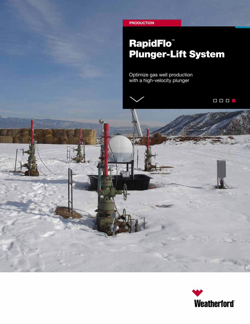
RapidFlo™ Plunger-Lift System
PRODUCTION
Optimize gas well production with a high-velocity plunger
2 © 2015 Weatherford. All rights reserved.
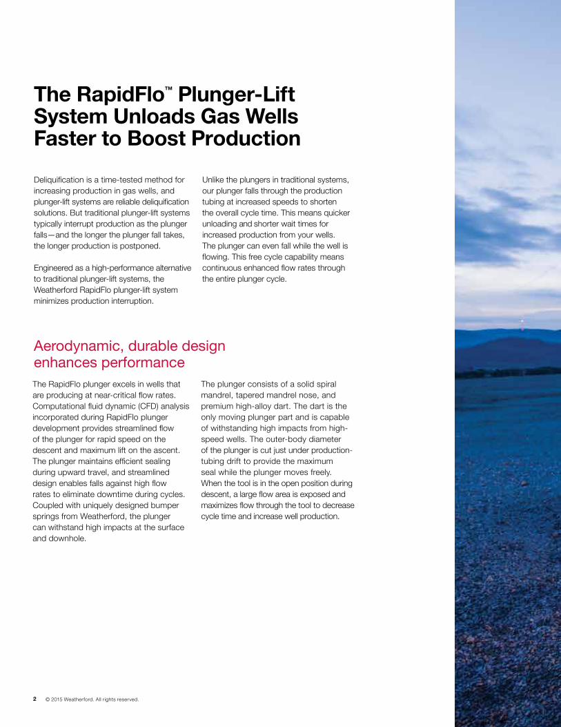
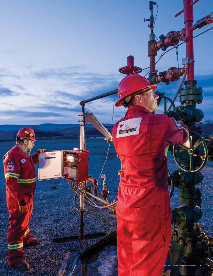
Deliquification is a time-tested method for increasing production in gas wells, and plunger-lift systems are reliable deliquification solutions. But traditional plunger-lift systems typically interrupt production as the plunger falls—and the longer the plunger fall takes, the longer production is postponed.
Engineered as a high-performance alternative to traditional plunger-lift systems, the Weatherford RapidFlo plunger-lift system minimizes production interruption.
Unlike the plungers in traditional systems, our plunger falls through the production tubing at increased speeds to shorten the overall cycle time. This means quicker unloading and shorter wait times for increased production from your wells. The plunger can even fall while the well is flowing. This free cycle capability means continuous enhanced flow rates through the entire plunger cycle.
The RapidFlotm Plunger-Lift System Unloads Gas Wells Faster to Boost Production
The RapidFlo plunger excels in wells that are producing at near-critical flow rates. Computational fluid dynamic (CFD) analysis incorporated during RapidFlo plunger development provides streamlined flow of the plunger for rapid speed on the descent and maximum lift on the ascent. The plunger maintains efficient sealing during upward travel, and streamlined design enables falls against high flow rates to eliminate downtime during cycles. Coupled with uniquely designed bumper springs from Weatherford, the plunger can withstand high impacts at the surface and downhole.
The plunger consists of a solid spiral mandrel, tapered mandrel nose, and premium high-alloy dart. The dart is the only moving plunger part and is capable of withstanding high impacts from high-speed wells. The outer-body diameter of the plunger is cut just under production- tubing drift to provide the maximum seal while the plunger moves freely. When the tool is in the open position during descent, a large flow area is exposed and maximizes flow through the tool to decrease cycle time and increase well production.
Aerodynamic, durable design enhances performance
© 2015 Weatherford. All rights reserved. 3© 2015 Weatherford. All rights reserved. 3
4 © 2015 Weatherford. All rights reserved.
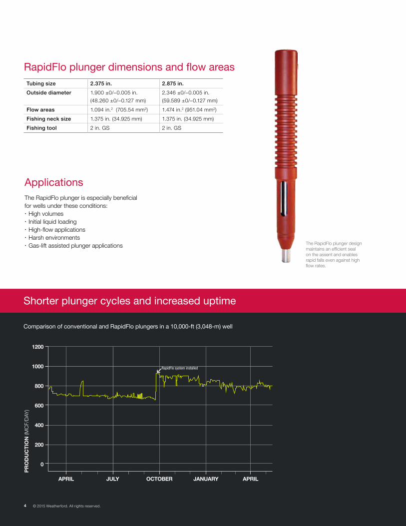
RapidFlo plunger dimensions and flow areas
ApplicationsThe RapidFlo plunger is especially beneficial for wells under these conditions: x High volumes x Initial liquid loading x High-flow applications x Harsh environments x Gas-lift assisted plunger applications
1200
1000
800
600
400
200
0
APRIL JULY OCTOBER JANUARY APRIL
RapidFlo system installed
Comparison of conventional and RapidFlo plungers in a 10,000-ft (3,048-m) well
PR
OD
UC
TIO
N (M
CF/
DAY
)
The RapidFlo plunger design maintains an efficient seal on the assent and enables rapid falls even against high flow rates.
Shorter plunger cycles and increased uptime
4 © 2015 Weatherford. All rights reserved.
Tubing size 2.375 in. 2.875 in.
Outside diameter 1.900 ±0/ –0.005 in.
(48.260 ±0/–0.127 mm)
2.346 ±0/–0.005 in.
(59.589 ±0/–0.127 mm)
Flow areas 1.094 in.2 (705.54 mm2) 1.474 in.2 (951.04 mm2)
Fishing neck size 1.375 in. (34.925 mm) 1.375 in. (34.925 mm)
Fishing tool 2 in. GS 2 in. GS
© 2015 Weatherford. All rights reserved. 5
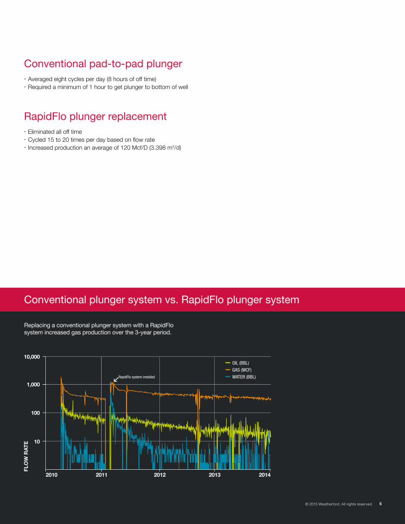
Conventional plunger system vs. RapidFlo plunger system
RapidFlo plunger replacement x Eliminated all off time x Cycled 15 to 20 times per day based on flow rate x Increased production an average of 120 Mcf/D (3.398 m3/d)
Conventional pad-to-pad plunger x Averaged eight cycles per day (8 hours of off time) x Required a minimum of 1 hour to get plunger to bottom of well
Replacing a conventional plunger system with a RapidFlo system increased gas production over the 3-year period.
10,000
1,000
100
10
2010 2011 2012 2013 2014
RapidFlo system installed
OIL (BBL)
GAS (MCF)
WATER (BBL)
FLO
W R
AT
E
© 2015 Weatherford. All rights reserved. 5
6 © 2015 Weatherford. All rights reserved.
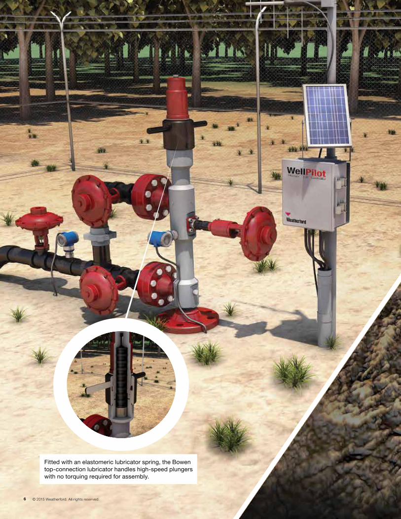
Fitted with an elastomeric lubricator spring, the Bowen top-connection lubricator handles high-speed plungers with no torquing required for assembly.
7© 2015 Weatherford. All rights reserved.
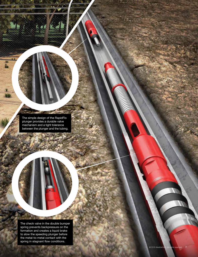
The check valve in the double bumper spring prevents backpressure on the formation and creates a liquid brake to slow the speeding plunger before the metal-to-metal contact with the spring in stagnant flow conditions.
The simple design of the RapidFlo plunger provides a durable valve mechanism and a tight tolerance between the plunger and the tubing.
8 © 2015 Weatherford. All rights reserved.
© 2015 Weatherford. All rights reserved. 9
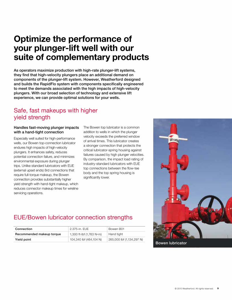
Bowen lubricator
As operators maximize production with high-rate plunger-lift systems, they find that high-velocity plungers place an additional demand on components of the plunger-lift system. However, Weatherford designed and builds the RapidFlo system with components specifically engineered to meet the demands associated with the high impacts of high-velocity plungers. With our broad selection of technology and extensive lift experience, we can provide optimal solutions for your wells.
EUE/Bowen lubricator connection strengths
Handles fast-moving plunger impacts with a hand-tight connection
Especially well suited for high-performance wells, our Bowen top-connection lubricator endures high impacts of high-velocity plungers. It enhances safety, reduces potential connection failure, and minimizes environmental exposure during plunger trips. Unlike standard lubricators with EUE (external upset ends) 8rd connections that require full-torque makeup, the Bowen connection provides substantially higher yield strength with hand-tight makeup, which reduces connector makeup times for wireline servicing operations.
The Bowen top lubricator is a common addition to wells in which the plunger velocity exceeds the preferred window of arrival times. This lubricator creates a stronger connection that protects the critical lubricator-spring housing against failures caused by high plunger velocities. By comparison, the impact load rating of industry-standard lubricators with EUE top connections between the flow-tee body and the top spring housing is significantly lower.
Optimize the performance of your plunger-lift well with our suite of complementary products
Safe, fast makeups with higher yield strength
Connection 2.375-in. EUE Bowen B01
Recommended makeup torque 1,300 ft-lbf (1,763 Nm) Hand tight
Yield point 104,340 lbf (464,104 N) 265,000 lbf (1,134,297 N)
10 © 2015 Weatherford. All rights reserved.
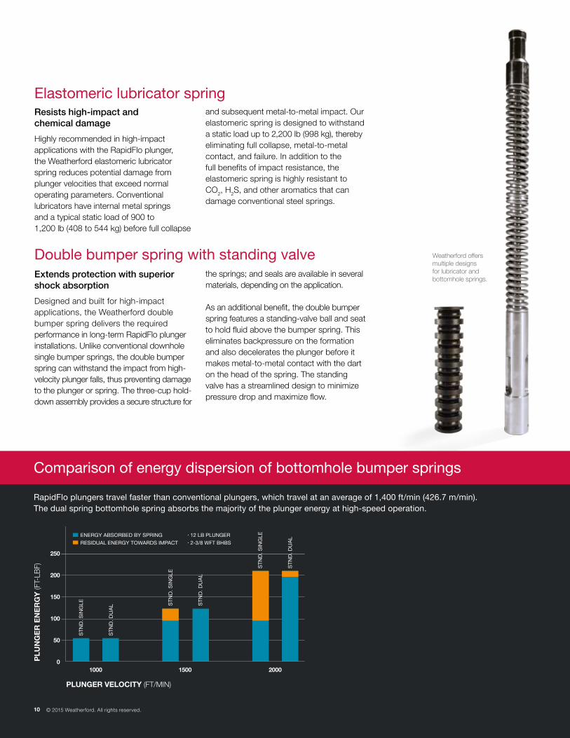
RapidFlo plungers travel faster than conventional plungers, which travel at an average of 1,400 ft/min (426.7 m/min). The dual spring bottomhole spring absorbs the majority of the plunger energy at high-speed operation.
Comparison of energy dispersion of bottomhole bumper springs
Resists high-impact and chemical damage
Highly recommended in high-impact applications with the RapidFlo plunger, the Weatherford elastomeric lubricator spring reduces potential damage from plunger velocities that exceed normal operating parameters. Conventional lubricators have internal metal springs and a typical static load of 900 to 1,200 lb (408 to 544 kg) before full collapse
and subsequent metal-to-metal impact. Our elastomeric spring is designed to withstand a static load up to 2,200 lb (998 kg), thereby eliminating full collapse, metal-to-metal contact, and failure. In addition to the full benefits of impact resistance, the elastomeric spring is highly resistant to CO2, H2S, and other aromatics that can damage conventional steel springs.
Elastomeric lubricator spring
Extends protection with superior shock absorption
Designed and built for high-impact applications, the Weatherford double bumper spring delivers the required performance in long-term RapidFlo plunger installations. Unlike conventional downhole single bumper springs, the double bumper spring can withstand the impact from high- velocity plunger falls, thus preventing damage to the plunger or spring. The three-cup hold-down assembly provides a secure structure for
the springs; and seals are available in several materials, depending on the application. As an additional benefit, the double bumper spring features a standing-valve ball and seat to hold fluid above the bumper spring. This eliminates backpressure on the formation and also decelerates the plunger before it makes metal-to-metal contact with the dart on the head of the spring. The standing valve has a streamlined design to minimize pressure drop and maximize flow.
Double bumper spring with standing valve
250
200
150
100
50
01000 1500 2000
ST
ND
. SIN
GLE
ST
ND
. DU
AL S
TN
D. S
ING
LE
ST
ND
. DU
AL
ST
ND
. SIN
GLE
ST
ND
. DU
ALENERGY ABSORBED BY SPRING
RESIDUAL ENERGY TOWARDS IMPACT
12 LB PLUNGER
2-3/8 WFT BHBS
PLUNGER VELOCITY (FT/MIN)
PLU
NG
ER
EN
ER
GY
(FT-
LBF)
10 © 2015 Weatherford. All rights reserved.
Weatherford offers multiple designs for lubricator and bottomhole springs.
© 2015 Weatherford. All rights reserved. 11
FLO
W R
AT
E
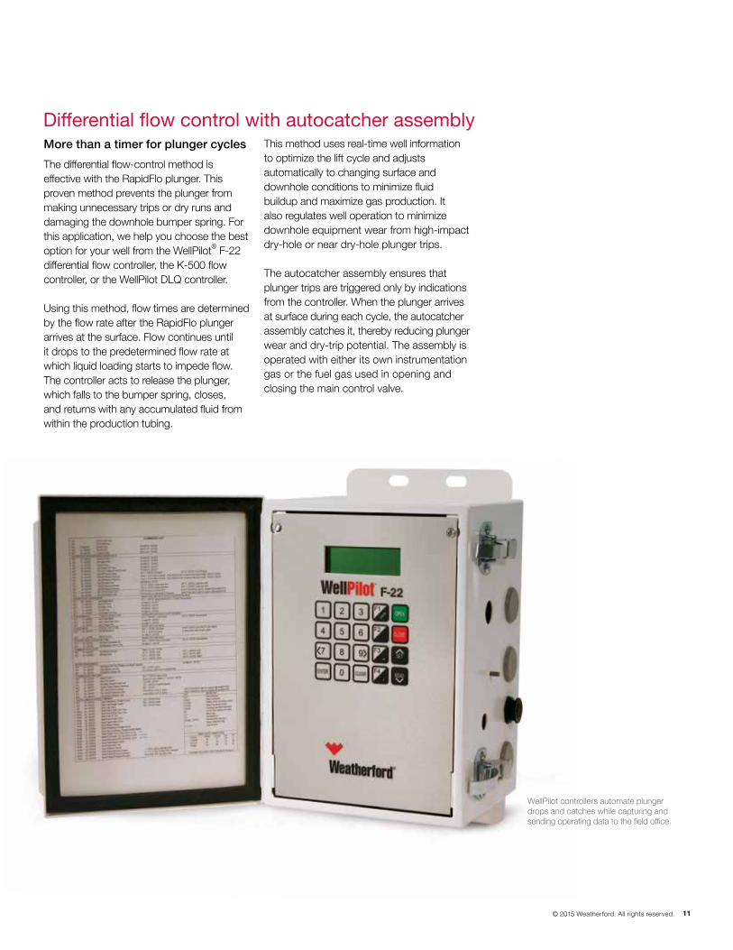
Differential flow control with autocatcher assemblyMore than a timer for plunger cycles
The differential flow-control method is effective with the RapidFlo plunger. This proven method prevents the plunger from making unnecessary trips or dry runs and damaging the downhole bumper spring. For this application, we help you choose the best option for your well from the WellPilot® F-22 differential flow controller, the K-500 flow controller, or the WellPilot DLQ controller.
Using this method, flow times are determined by the flow rate after the RapidFlo plunger arrives at the surface. Flow continues until it drops to the predetermined flow rate at which liquid loading starts to impede flow. The controller acts to release the plunger, which falls to the bumper spring, closes, and returns with any accumulated fluid from within the production tubing.
This method uses real-time well information to optimize the lift cycle and adjusts automatically to changing surface and downhole conditions to minimize fluid buildup and maximize gas production. It also regulates well operation to minimize downhole equipment wear from high-impact dry-hole or near dry-hole plunger trips.
The autocatcher assembly ensures that plunger trips are triggered only by indications from the controller. When the plunger arrives at surface during each cycle, the autocatcher assembly catches it, thereby reducing plunger wear and dry-trip potential. The assembly is operated with either its own instrumentation gas or the fuel gas used in opening and closing the main control valve.
WellPilot controllers automate plunger drops and catches while capturing and sending operating data to the field office.
weatherford.com
Weatherford products and services are subject to the Company’s standard terms and conditions, available on request or at weatherford.com. For more information contact an authorized Weatherford representative. Unless noted otherwise, trademarks and service marks herein are the property of Weatherford and may be registered in the United States and/or other countries. Weatherford products named herein may be protected by one or more U.S. and/or foreign patents. Specifications are subject to change without notice. Weatherford sells its products and services in accordance with the terms and conditions set forth in the applicable contract between Weatherford and the client.
© 2015 Weatherford. All rights reserved. 9687.00
Weatherford brings global expertise, comprehensive solutions, and an unparalleled depth of products for you to optimize your wells. For more information on the RapidFlo plunger system or any of our production optimizing solutions, contact us at [email protected].