Embed Size (px)
Citation preview
Plunger lift insPection and rePlacement: recommended guidelines

2
Plunger lift insPection and rePlacement: recommended guidelines
There are a number of methodologies for determining when to inspect and replace the plunger in a plunger lift well. Production Control Services (PCS) does not adhere to any single method, but instead suggests that operators and their service technicians consider a number of variables, which will be discussed here.
The plunger is the moving part in the plunger lift system. It will naturally wear with use and time and, as it does, will become less effective. The expense of regular plunger replacement is negligible as compared to the production gained from a plunger lift system that is operating at peak performance. PCS can establish a scheduled replacement program, based on your specific well characteristics and budget, to ensure your plunger lift system—and wells—are producing optimally.
Regular plunger replacement offers these benefits:Extends the life, and productivity, of a well ➤
Enables the well to more easily lift and remove liquids ➤
Lowers long-term operating and maintenance costs ➤
Ensures better removal of paraffin, hydrate and other solids ➤
Decreases the risk and cost of damage to downhole equipment ➤
PCS recommends that most plungers be inspected every three months. Flow-Thru™ plungers (also called continuous flow or by-pass plungers) should be inspected monthly.
In wells where corrosive gases are present—such as CO2 or H2S—the same guidelines will apply, assuming the correct plunger material is being used. The type of material depends on the percentage of corrosion detected. Please consult PCS for assistance in choosing the correct material for your specific well conditions.
It is also advised that the plunger be checked more frequently when first installing a plunger lift system. This allows the operator and PCS to establish the baseline characteristics of the well. This information can then be used to determine the appropriate schedule for future inspections, as well as make any changes to the operating settings and the plunger selection to ensure optimum performance.
Keep your plunger lift system operating at peak performance
Plunger inspection guidelines
3
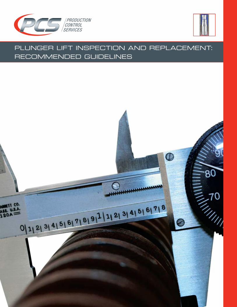
The production rate changes significantly ➤
A too-fast plunger trip occurs ➤
Ideal travel speed is 700-900 feet per minute. Most controllers ➤
store a history of plunger travel speeds. If a too-fast trip has occurred, both the plunger and lubricator spring should be inspected immediately. If one or both have been damaged, they should be replaced before excessive damage occurs that will likely require a wireline or rig job.
Before any on-site inspections, make sure you are wearing ➤
company-required PPE (Personal Protective Equipment). Complete a JSA (Job Safety Analysis) to identify potential hazards ➤
such as slipping or falling. Determine if a ladder or fall protection will be needed to conduct a ➤
safe inspection.
Visible wear (see Inspection Methods by Plunger Type) ➤
Wear as measured by calipers or a gauge ring ➤
(see Plunger O.D. Wear Allowances chart)Missed arrivals ➤
Quick arrivals ➤
Erratic plunger travel times ➤
>10% change in typical daily well production ➤
Inspect the plunger immediately if any of the following occur
Always put safety first
Signs that a plunger may need to be replaced
4
insPection methods for Pad Plungers
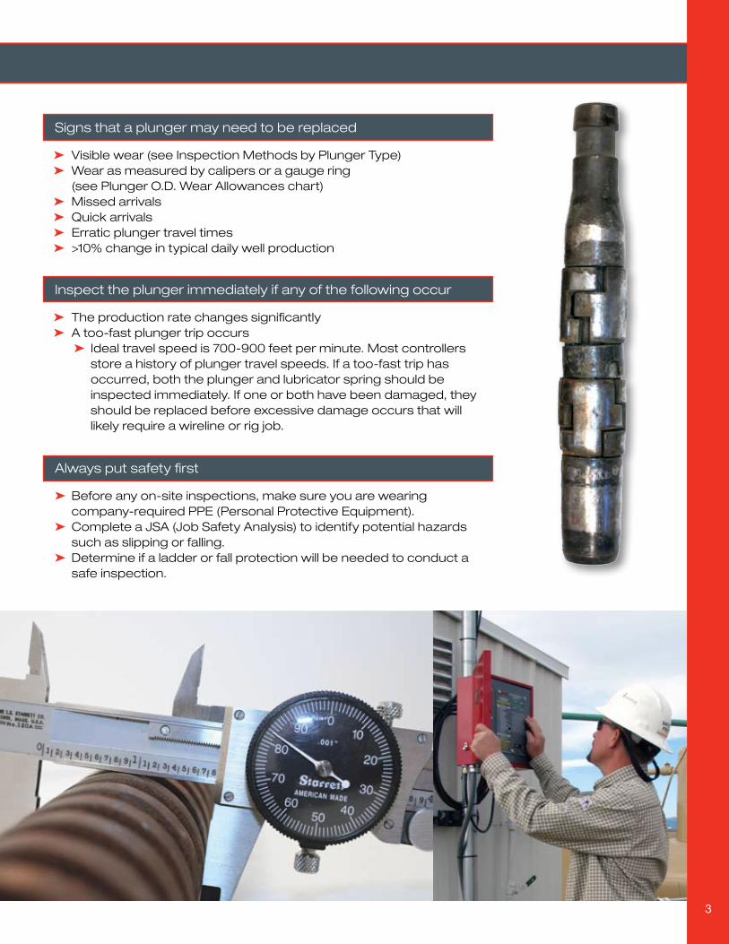
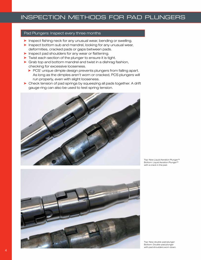
Inspect fishing neck for any unusual wear, bending or swelling. ➤
Inspect bottom sub and mandrel, looking for any unusual wear, ➤
deformities, cracked pads or gaps between pads. Inspect pad shoulders for any wear or flattening. ➤
Twist each section of the plunger to ensure it is tight. ➤
Grab top and bottom mandrel and twist in a dishrag fashion, ➤
checking for excessive looseness.PCS’ unique dimple design prevents plungers from falling apart. ➤
As long as the dimples aren’t worn or cracked, PCS plungers will run properly, even with slight looseness.
Check tension of pad springs by squeezing all pads together. A drift ➤
gauge ring can also be used to test spring tension.
Pad Plungers: Inspect every three months
Top: New Liquid Aeration Plunger™Bottom: Liquid Aeration Plunger™ with a crack in the pad.
Top: New double-pad plungerBottom: Double-pad plunger with pad shoulders worn down.
5
insPection methods for solid Plungers
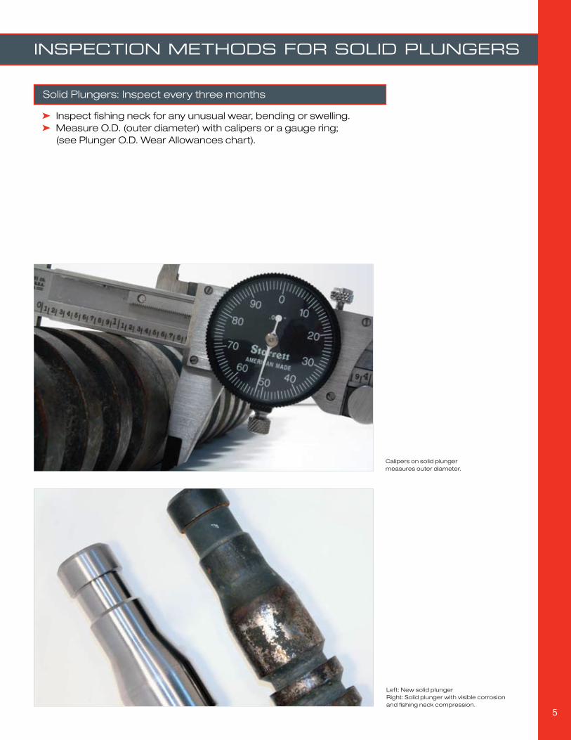
Inspect fishing neck for any unusual wear, bending or swelling. ➤
Measure O.D. (outer diameter) with calipers or a gauge ring; ➤
(see Plunger O.D. Wear Allowances chart).
Solid Plungers: Inspect every three months
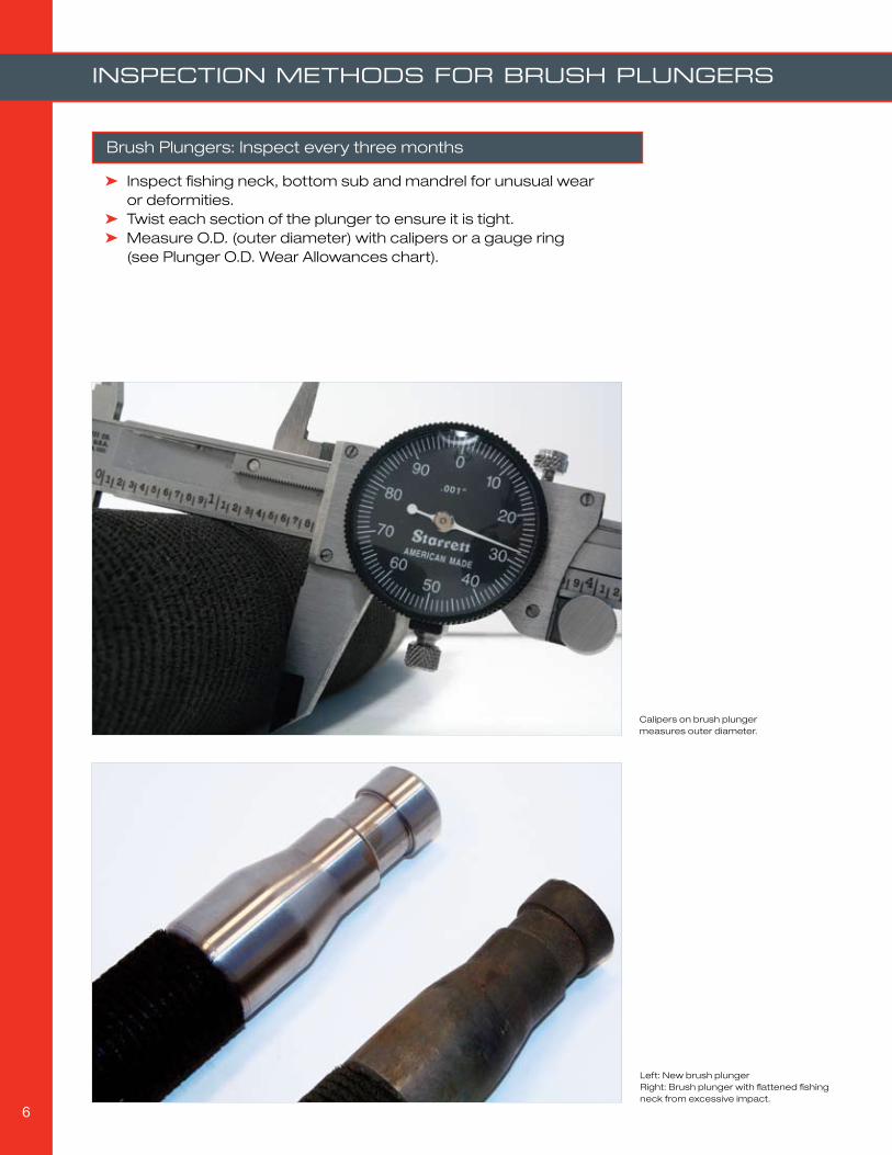
Left: New solid plungerRight: Solid plunger with visible corrosion and fishing neck compression.
Calipers on solid plunger measures outer diameter.
6
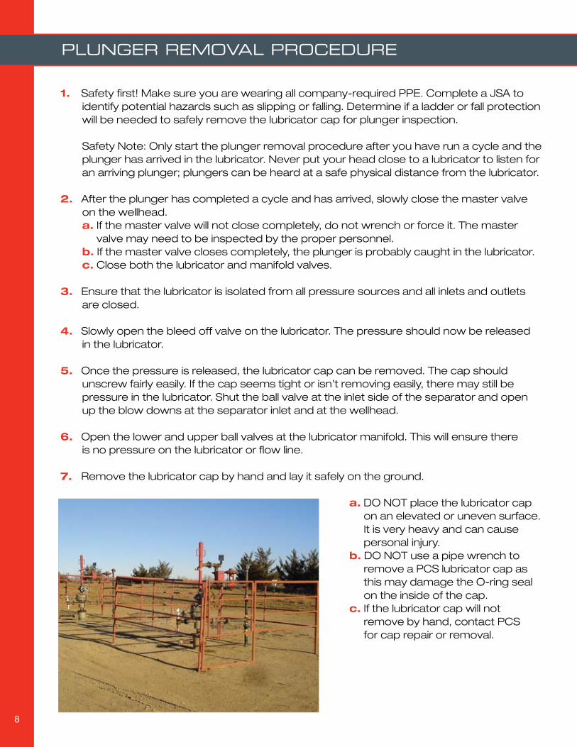
Inspect fishing neck, bottom sub and mandrel for unusual wear ➤
or deformities.Twist each section of the plunger to ensure it is tight. ➤
Measure O.D. (outer diameter) with calipers or a gauge ring ➤
(see Plunger O.D. Wear Allowances chart).
Brush Plungers: Inspect every three months
insPection methods for brush Plungers
Calipers on brush plunger measures outer diameter.
Left: New brush plungerRight: Brush plunger with flattened fishing neck from excessive impact.

7
Inspect fishing neck for any unusual wear, bending or swelling. ➤
Test shift rods or pucks to ensure they are shifting properly. ➤
Twist each section of the plunger to ensure it is tight. ➤
Measure O.D. (outer diameter) with calipers or a gauge ring ➤
(see Plunger O.D. Wear Allowances chart).
Flow-Thru™ (By-Pass) Plungers: Inspect monthly
insPection methods for flow-thru™ Plungers
Calipers on Flow-Thru plunger measures outer diameter.
Left: New Flow-Thru PlungerRight: Flow-Thru Plunger with swollen fishing neck from excessive impact.
8
Plunger removal Procedure
Safety first! Make sure you are wearing all company-required PPE. Complete a JSA to 1. identify potential hazards such as slipping or falling. Determine if a ladder or fall protection will be needed to safely remove the lubricator cap for plunger inspection. Safety Note: Only start the plunger removal procedure after you have run a cycle and the plunger has arrived in the lubricator. Never put your head close to a lubricator to listen for an arriving plunger; plungers can be heard at a safe physical distance from the lubricator.
After the plunger has completed a cycle and has arrived, slowly close the master valve 2. on the wellhead. a. If the master valve will not close completely, do not wrench or force it. The master valve may need to be inspected by the proper personnel. b. If the master valve closes completely, the plunger is probably caught in the lubricator. c. Close both the lubricator and manifold valves.
Ensure that the lubricator is isolated from all pressure sources and all inlets and outlets 3. are closed.
Slowly open the bleed off valve on the lubricator. The pressure should now be released 4. in the lubricator.
Once the pressure is released, the lubricator cap can be removed. The cap should 5. unscrew fairly easily. If the cap seems tight or isn’t removing easily, there may still be pressure in the lubricator. Shut the ball valve at the inlet side of the separator and open up the blow downs at the separator inlet and at the wellhead.
Open the lower and upper ball valves at the lubricator manifold. This will ensure there 6. is no pressure on the lubricator or flow line.
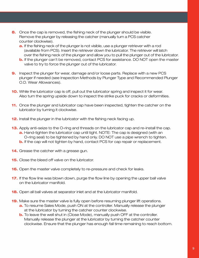
Remove the lubricator cap by hand and lay it safely on the ground. 7.
a. DO NOT place the lubricator cap on an elevated or uneven surface. It is very heavy and can cause personal injury. b. DO NOT use a pipe wrench to remove a PCS lubricator cap as this may damage the O-ring seal on the inside of the cap. c. If the lubricator cap will not remove by hand, contact PCS for cap repair or removal.
9
Once the cap is removed, the fishing neck of the plunger should be visible. 8. Remove the plunger by releasing the catcher (manually turn a PCS catcher counter clockwise). a. If the fishing neck of the plunger is not visible, use a plunger retriever with a rod (available from PCS). Insert the retriever down the lubricator. The retriever will latch over the fishing neck of the plunger and allow you to pull the plunger out of the lubricator. b. If the plunger can’t be removed, contact PCS for assistance. DO NOT open the master valve to try to force the plunger out of the lubricator.
Inspect the plunger for wear, damage and/or loose parts. Replace with a new PCS 9. plunger if needed (see Inspection Methods by Plunger Type and Recommended Plunger O.D. Wear Allowances).
While the lubricator cap is off, pull out the lubricator spring and inspect it for wear. 10. Also turn the spring upside down to inspect the strike puck for cracks or deformities.
Once the plunger and lubricator cap have been inspected, tighten the catcher on the 11. lubricator by turning it clockwise.
Install the plunger in the lubricator with the fishing neck facing up. 12.
Apply anti-seize to the O-ring and threads on the lubricator cap and re-install the cap. 13. a. Hand-tighten the lubricator cap until tight. NOTE: The cap is designed (with an O-ring seal) to be tightened by hand only. DO NOT use a pipe wrench to tighten. b. If the cap will not tighten by hand, contact PCS for cap repair or replacement.
Grease the catcher with a grease gun. 14.
Close the bleed off valve on the lubricator. 15.
Open the master valve completely to re-pressure and check for leaks. 16.
If the flow line was blown down, purge the flow line by opening the upper ball valve 17. on the lubricator manifold.
Open all ball valves at separator inlet and at the lubricator manifold. 18.
Make sure the master valve is fully open before resuming plunger lift operations. 19. a. To resume Sales Mode, push ON at the controller. Manually release the plunger at the lubricator by turning the catcher counter clockwise. b. To leave the well shut in (Close Mode), manually push OFF at the controller. Manually release the plunger at the lubricator by turning the catcher counter clockwise. Ensure that the plunger has enough fall time remaining to reach bottom.
10
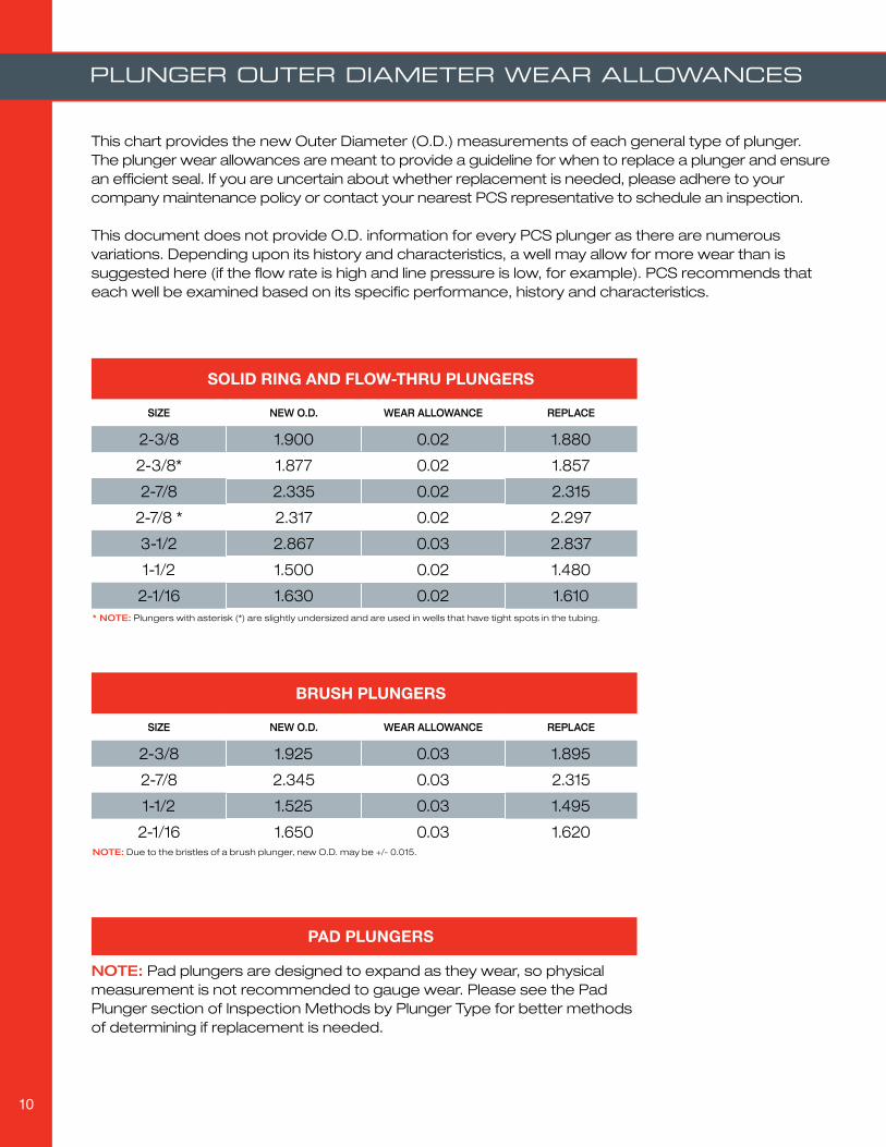
This chart provides the new Outer Diameter (O.D.) measurements of each general type of plunger. The plunger wear allowances are meant to provide a guideline for when to replace a plunger and ensure an efficient seal. If you are uncertain about whether replacement is needed, please adhere to your company maintenance policy or contact your nearest PCS representative to schedule an inspection.
This document does not provide O.D. information for every PCS plunger as there are numerous variations. Depending upon its history and characteristics, a well may allow for more wear than is suggested here (if the flow rate is high and line pressure is low, for example). PCS recommends that each well be examined based on its specific performance, history and characteristics.
Plunger outer diameter wear allowances
SOLID RING AND FLOW-THRU PLUNGERS
SIZE NEW O.D. WEAR ALLOWANCE REPLACE
2-3/8 1.900 0.02 1.880
2-3/8* 1.877 0.02 1.857
2-7/8 2.335 0.02 2.315
2-7/8 * 2.317 0.02 2.297
3-1/2 2.867 0.03 2.837
1-1/2 1.500 0.02 1.480
2-1/16 1.630 0.02 1.610
BRUSH PLUNGERS
SIZE NEW O.D. WEAR ALLOWANCE REPLACE
2-3/8 1.925 0.03 1.895
2-7/8 2.345 0.03 2.315
1-1/2 1.525 0.03 1.495
2-1/16 1.650 0.03 1.620
PAD PLUNGERS
NOTE: Due to the bristles of a brush plunger, new O.D. may be +/- 0.015.
* NOTE: Plungers with asterisk (*) are slightly undersized and are used in wells that have tight spots in the tubing.
NOTE: Pad plungers are designed to expand as they wear, so physical measurement is not recommended to gauge wear. Please see the Pad Plunger section of Inspection Methods by Plunger Type for better methods of determining if replacement is needed.

11
BHBS-238LCSV-BH
It is recommended that the lubricator spring and strike puck be inspected each time the cap is removed or when a plunger inspection is performed. PCS’ patented Poly-SpringTM is engineered to absorb the plunger’s impact and withstands arrival speeds up to 3,000 feet per minute. Unlike metal springs, the PCS Poly-Spring will not break down or lose its memory. Carefully unscrew and remove the lubricator cap. Pull out the spring and inspect for wear. Turn the spring upside down and inspect the strike puck for cracks or deformities. If the spring is stuck in the lubricator, contact your PCS Service Technician to replace the spring and strike puck.
equiPment insPection guidelines
Seated, Tubing Stop and Latch Down Bumper SpringsExample Part Numbers:
BHBS-238LCSV-BH ➤
TS-238 (Tubing Stop) ➤
BHBS-238LDL (Latch Down Bumper Spring) ➤
Because of the wireline expense involved, springs are seldom inspected unless a problem occurs. It is recommended that they be inspected once per year, ideally when a wireline rig is on-site performing other work. If the plunger becomes lodged and needs to be retrieved using a wireline, the spring should also be pulled and inspected at that time.
Visually inspect the spring for cracks, a bent or mushroomed fishing neck, and scale build up. Also, test for good spring tension and tightness of the assembly. If the tension is soft, or if there are any visual defects or damage, replace the spring. If tightening only is needed, contact your PCS service technician.
Free Floating Bumper SpringExample Part Number: BHBS-238FF
PCS recommends inspecting this type of spring every three months, or during typical plunger inspections. The spring can be removed with a fishing neck retrieval plunger (best for non-magnetic stainless steel plungers) or a magnetic retrieval plunger (best for damaged equipment).
If the spring lodges in the tubing above the liquid level, the spring should be removed immediately using a wireline. This will avoid potential damage to the lubricator cap and plunger as a result of dry runs.
NOTE: PCS Viton® Plungers can eliminate the need for downhole springs. For information on styles and sizes available, contact your PCS sales and service office.
For additional information or questions about plunger maintenance and replacement, please contact your local PCS sales and service office. To find the PCS office nearest you, please visit www.pcslift.com
Lubricator spring inspection guidelines
Bottom hole bumper spring inspection guidelines
PCS Plunger Lift / Opti-Flow™ Gas Lift / Nitro2Go™ Nitrogen Generation / PCS Well Site SCADA
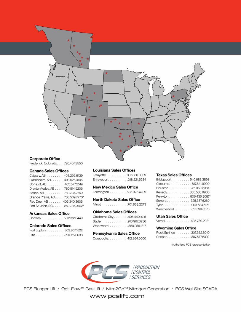
Corporate OfficeFrederick, Colorado. . . 720.407.3550
Canada Sales OfficesCalgary, AB . . . . . . . . 403.266.6139Claresholm, AB. . . . . . 403.625.4105Consort, AB. . . . . . . . .403.577.2519Drayton Valley, AB . . . . .780.514.5206Edson, AB . . . . . . . . . 780.723.2759Grande Prairie, AB. . . . 780.539.7773 *Red Deer, AB . . . . . . . 403.340.3605Fort St. John, BC. . . . . 250.785.0762 *
Arkansas Sales OfficeConway . . . . . . . . . . 501.932.0449
Colorado Sales OfficesFort Lupton . . . . . . . . .303.857.1522
Rifle . . . . . . . . . . . . . 970.625.0638
Louisiana Sales OfficesLafayette. . . . . . . . . . 337.886.0009Shreveport . . . . . . . . .318.221.5934
New Mexico Sales OfficeFarmington . . . . . . . . 505.326.4239
North Dakota Sales OfficeMinot . . . . . . . . . . . . .701.838.2273
Oklahoma Sales OfficesOklahoma City . . . . . . .405.440.1015Stigler. . . . . . . . . . . . .918.967.3236Woodward . . . . . . . . . 580.256.1317
Pennsylvania Sales OfficeCoraopolis. . . . . . . . . 412.264.6000
Texas Sales OfficesBridgeport. . . . . . . . . 940.683.3898Cleburne. . . . . . . . . . . 817.641.9900Houston . . . . . . . . . . 281.350.2084Kenedy. . . . . . . . . . . 830.583.9900 Perryton . . . . . . . . . . 806.435.3087 *Sonora . . . . . . . . . . . 325.387.6260Tyler. . . . . . . . . . . . . .903.534.5151Weatherford . . . . . . . .817.599.6570
Utah Sales OfficeVernal. . . . . . . . . . . . 435.789.2031
Wyoming Sales OfficeRock Springs . . . . . . . .307.362.6010Casper . . . . . . . . . . . .307.577.6392
www.pcslift.com
*Authorized PCS representative