Embed Size (px)
Citation preview
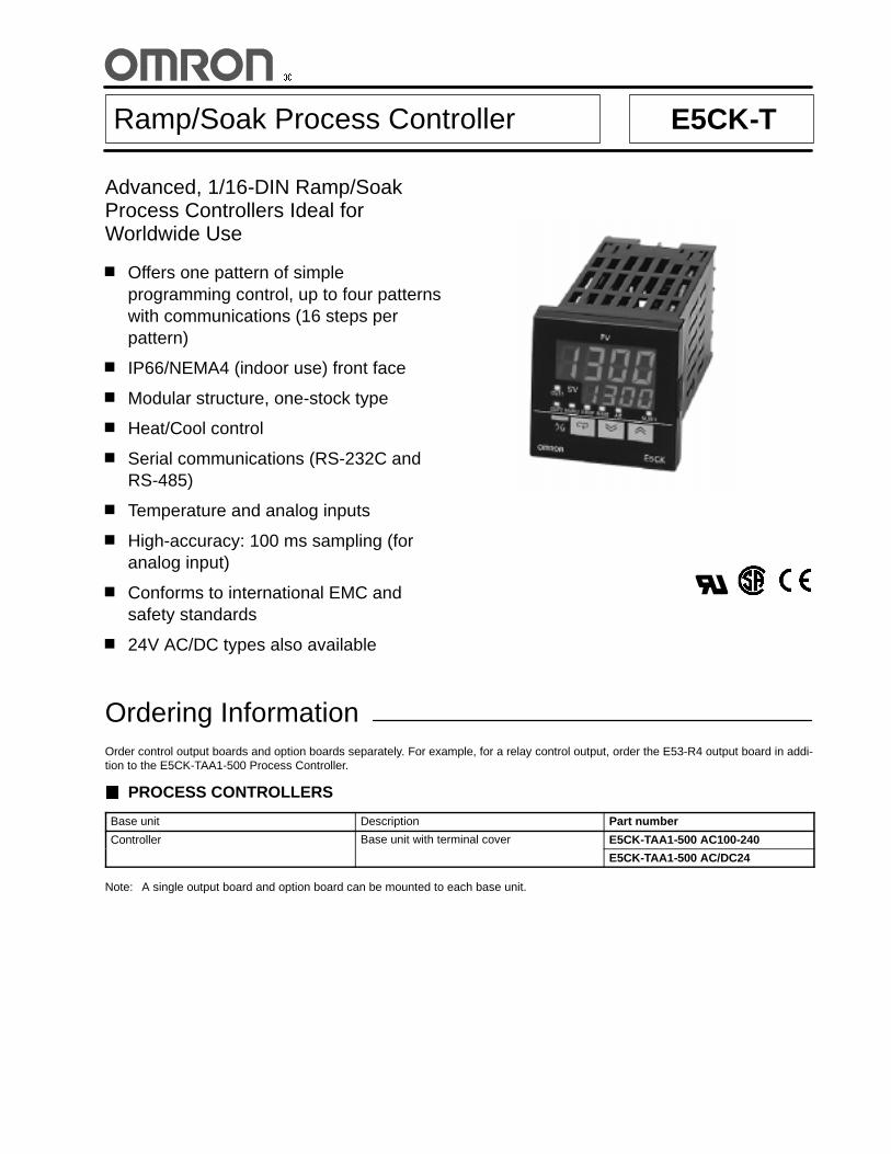
Ramp/Soak Process Controller E5CK-T
Advanced, 1/16-DIN Ramp/SoakProcess Controllers Ideal forWorldwide Use
Offers one pattern of simpleprogramming control, up to four patternswith communications (16 steps perpattern)
IP66/NEMA4 (indoor use) front face
Modular structure, one-stock type
Heat/Cool control
Serial communications (RS-232C andRS-485)
Temperature and analog inputs
High-accuracy: 100 ms sampling (foranalog input)
Conforms to international EMC andsafety standards
24V AC/DC types also available
Ordering InformationOrder control output boards and option boards separately. For example, for a relay control output, order the E53-R4 output board in addi-tion to the E5CK-TAA1-500 Process Controller.
PROCESS CONTROLLERS
Base unit Description Part number
Controller Base unit with terminal cover E5CK-TAA1-500 AC100-240
E5CK-TAA1-500 AC/DC24
Note: A single output board and option board can be mounted to each base unit.
E5CK-T E5CK-T
OUTPUT BOARDS
Item Description Part number
Output board Relay/Relay E53-R4R4
Pulse (NPN)/Relay E53-Q4R4
Pulse (PNP)/Relay E53-Q4HR4
Linear (4 to 20 mA)/Relay E53-C4R4
Linear (0 to 20 mA)/Relay E53-C4DR4
Linear (0 to 10 V)/Relay E53-V44R4
Pulse (NPN)/Pulse (NPN) E53-Q4Q4
Pulse (PNP)/Pulse (PNP) E53-Q4HQ4H
OPTION BOARDS
Item Description Part number
Option board RS-232C E53-CK01
RS-485 E53-CK03
Event input: 1 point E53-CKB
Transfer output (4 to 20 mA) E53-CKF
Inspection Report
The Process Controller can be provided together with an inspection report. Refer to the following legend with the suffix “K” when orderinga model provided together with an inspection report: E5CK-TAA1-K, E53-CKF-K
ACCESSORIES (ORDER SEPARATELY)
Terminal Cover
Item Part number
Terminal cover E53-COV07
TEMPERATURE RANGES
Platinum Resistance Thermometer
Input (See Note.) JPt100 Pt100
Range °C --199.9° to 650.0° --199.9° to 650.0°°F --199.9° to 999.9° --199.9° to 999.9°
Resolution (°C/°F) (main setting and alarm) 0 1
Note: Switch selectable.
E5CK-T E5CK-T
Thermocouple
Input (See Note.) K1 K2 J1 J2 T E L1 L2 U N R S B W PL
Range °C --200to1,300
0.0 to500.0
--100to 850
0.0 to400.0
--199.9to400.0
0 to600
--100to 850
0.0 to400.0
--199.9to400.0
--200to1,300
0 to1,700
0 to1,700
100 to1,800
0 to2,300
0 to1,300
°F --300to2,300
0.0 to900.0
--100to1,500
0.0 to750.0
--199.9to700.0
0 to1,100
--100to1,500
0.0 to750.0
--199.9to700.0
--300to2,300
0 to3,000
0 to3,000
300 to3,200
0 to4,100
0 to2,300
Resolution(°C/°F)(main settingand alarm)
2 3 4 5 6 7 8 9 10 11 12 13 14 15 16
Note: Switch selectable: Setting number is factory-set to 2 (K1).Thermocouple W is W/Re 5-26 (tungsten rhenium 5, tungsten rhenium 26).
Current/Voltage
Input (switch selectable) Current input Voltage input
4 to 20 mA 0 to 20 mA 1 to 5 V 0 to 5 V 0 to 10 V
Range One of following ranges depending on results of scaling--1999 to 9999--199.9 to 999.9--19.99 to 99.99--1.999 to 9.999
Resolution (°C/°F) main setting andalarm
17 18 19 20 21
Specifications RATINGS
Model E5CK-T (Standard) E5CK-T (24 V Type)
Supply voltage 100 to 240 VAC, 50/60 Hz 24 VAC/VDC, 50/60 Hz
Power consumption 15 VA 6 VA, 3.5 W
Operating voltage range 85% to 110% of rated supply voltage
Input Thermocouple K, J, T, E, L, U, N, R, S, B, W, PL
Platinum resistancethermometer
JPt100, Pt100
Current input 4 to 20 mA, 0 to 20 mA
Voltage input 1 to 5 V, 0 to 5 V, 1 to 10 V
Input impedance Current input 150 ΩVoltage input 1 MΩ min.
Control output According to Output Board (see Output Board Ratings and Characteristics)
Auxiliary output SPST-NO, 1 A at 250 VAC (resistive load)
Control method ON/OFF or advanced PID control
Setting method Digital setting using front panel keys or communications features
Indication method 7-segment digital display and LEDs
Additional functions Standard Manual output, heating/cooling control, SP limiter, loop burnout alarm, MV limiter,MV change rate limiter, input digital filter, input shift, run/reset, protect functions,scaling function
E5CK-T E5CK-T
CHARACTERISTICS
Indication accuracy(S N t 1 )
Thermocouple (±0.3% of indication value or ±1°C, whichever greater) ±1 digit max.y(See Note 1.) Platinum resistance
thermometer(±0.2% of indication value or ±0.8°C, whichever greater) ±1 digit max.
Analog input ±0.2% (of indication value) ±1 digit max.
Hysteresis 0.01% to 99.99% FS (in units of 0.01% FS)
Proportional band (P) 0.1% to 999.9% FS (in units of 0.1% FS)
Integral (reset) time (I) 0 to 3,999 s (in units of 1 s)
Derivative (rate) time (D) 0 to 3,999 s (in units of 1 s)
Control period 1 to 99 s (in units of 1 s)
Manual reset value 0.0% to 100.0% (in units of 0.1%)
Alarm setting range --1,999 to 9,999 or --199.9 or 999.9 (decimal point position dependent on inputtype)
Set time 0 to 99 hrs 59 min or 0 to 99 min 59 s
Program capacity 1 pattern, 16 steps (possible to use up to 4 patterns with the communicationsfunction.)
Programming method Time or ramp setting method
Time accuracy ±0.2% (±500 ms) of the set value
Sampling period(S N t 2 )
Temperature input 250 msg(See Note 2.) Analog input 100 ms
Insulation resistance 20 MΩ min. (at 500 VDC)
Dielectric strength 2,000 VAC, 50/60 Hz for 1 min between terminals of different polarities
Vibration resistance Malfunction: 10 to 55 Hz, 10 m/s2 (approx. 1G) for 10 min each in X, Y, and ZdirectionsDestruction: 10 to 55 Hz, 20 m/s2 (approx. 2G) for 2 hrs each in X, Y, and Zdirections
Shock resistance Malfunction: 200 m/s2 min. (approx. 20G), 3 times each in 6 directions(100 m/s2 (approx. 10G) applied to the relay)Destruction: 300 m/s2 min. (30G), 3 times each in 6 directions
Ambient temperature Operating --10°C to 55°C (with no icing)/3-year warranty period: --10°C to 50°CStorage --25°C to 65°C (with no icing)
Ambient humidity Operating 35% to 85%
Enclosure ratings Front panel NEMA4 for indoor use (equivalent to IP66)g
Rear case IEC standard IP20
Terminals IEC standard IP00
Memory protection Non-volatile memory (number of writings: 100,000 operations)
Weight Approx. 170 g;Adapter: approx. 10 g
(This table continues on the next page.)
Note: 1. The indication accuracy of the K1, T, and N thermocouples at a temperature of -100°C max. is ±2°C ±1 digit maximum. Theindication accuracy of the U and L thermocouples at any temperature is ±2°C ±1 digit maximum.The indication accuracy of the B thermocouple at a temperature of 400°C max. is unrestricted.The indication accuracy of the R and S thermocouples at a temperature of 200°C max. is ±3°C ±1 digit maximum.The indication accuracy of the W thermocouple at any temperature is (±0.3% of the indicated value or ±3°C, whichever is great-er) ±1 digit maximum. The indication accuracy of the PL thermocouple at any temperature is (±0.3% or ±2°C, whichever isgreater) ±1 digit maximum.
2. The sampling period of the standard model with CT and remote SP inputs is 250 ms.
E5CK-T E5CK-T
Characteristics Table -- continued from previous page
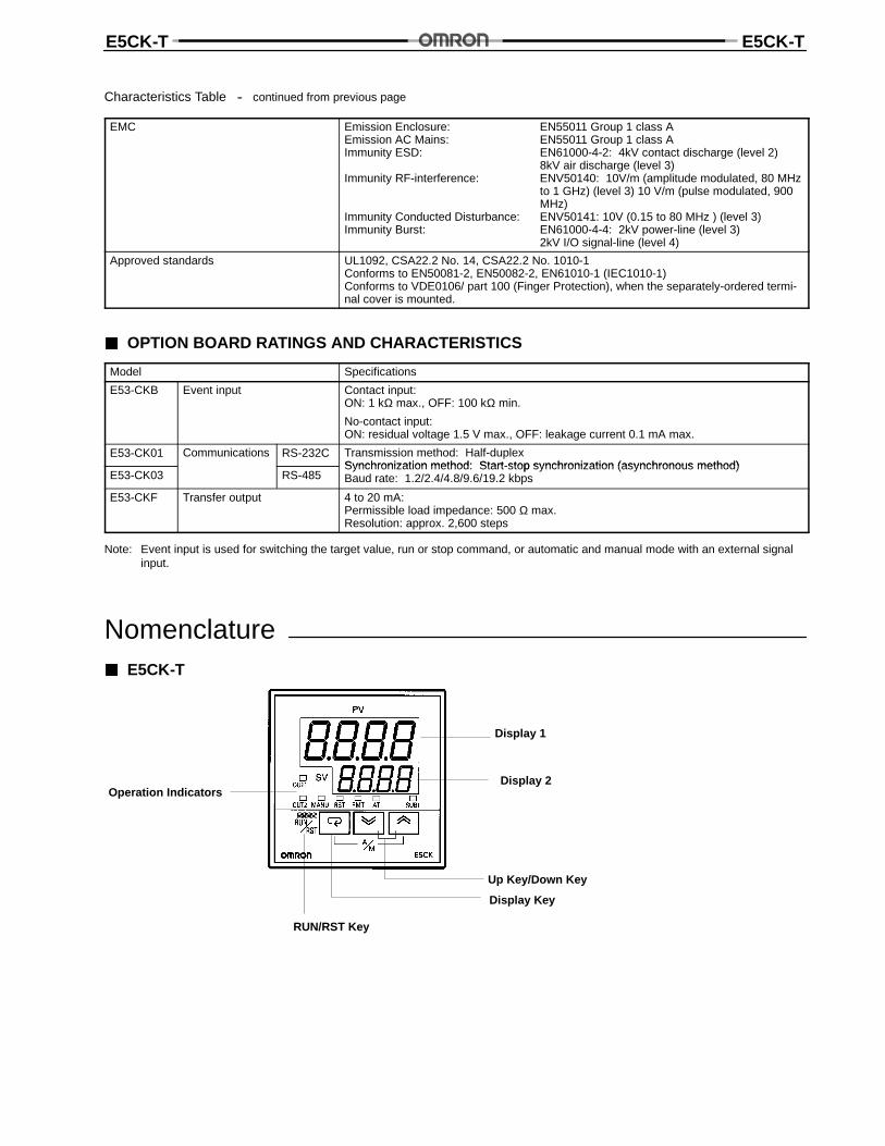
EMC Emission Enclosure: EN55011 Group 1 class AEmission AC Mains: EN55011 Group 1 class AImmunity ESD: EN61000-4-2: 4kV contact discharge (level 2)
8kV air discharge (level 3)Immunity RF-interference: ENV50140: 10V/m (amplitude modulated, 80 MHz
to 1 GHz) (level 3) 10 V/m (pulse modulated, 900MHz)
Immunity Conducted Disturbance: ENV50141: 10V (0.15 to 80 MHz ) (level 3)Immunity Burst: EN61000-4-4: 2kV power-line (level 3)
2kV I/O signal-line (level 4)
Approved standards UL1092, CSA22.2 No. 14, CSA22.2 No. 1010-1Conforms to EN50081-2, EN50082-2, EN61010-1 (IEC1010-1)Conforms to VDE0106/ part 100 (Finger Protection), when the separately-ordered termi-nal cover is mounted.
OPTION BOARD RATINGS AND CHARACTERISTICS
Model Specifications
E53-CKB Event input Contact input:ON: 1 kΩ max., OFF: 100 kΩ min.
No-contact input:ON: residual voltage 1.5 V max., OFF: leakage current 0.1 mA max.
E53-CK01 Communications RS-232C Transmission method: Half-duplexSynchronization method: Start-stop synchronization (asynchronous method)
E53-CK03 RS-485Synchronization method: Start-stop synchronization (asynchronous method)Baud rate: 1.2/2.4/4.8/9.6/19.2 kbps
E53-CKF Transfer output 4 to 20 mA:Permissible load impedance: 500 Ω max.Resolution: approx. 2,600 steps
Note: Event input is used for switching the target value, run or stop command, or automatic and manual mode with an external signalinput.
Nomenclature E5CK-T
Operation Indicators
RUN/RST Key
Up Key/Down Key
Display Key
Display 1
Display 2
E5CK-T E5CK-T
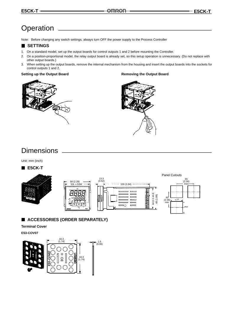
OperationNote: Before changing any switch settings, always turn OFF the power supply to the Process Controller
SETTINGS1. On a standard model, set up the output boards for control outputs 1 and 2 before mounting the Controller.
2. On a position-proportional model, the relay output board is already set, so this setup operation is unnecessary. (Do not replace withother output boards.)
3. When setting up the output boards, remove the internal mechanism from the housing and insert the output boards into the sockets forcontrol outputs 1 and 2.
Setting up the Output Board Removing the Output Board
DimensionsUnit: mm (inch)
E5CK-T
60(2.36)min.
Panel Cutouts65
(2.56)min.
48(1
.89)
58 (2.28)13.3
(0.52)100 (3.94)53L x 53W
44.8
X44
.8
ACCESSORIES (ORDER SEPARATELY)
Terminal Cover
E53-COV07
44.3(1.74)
44.3(1.74)
1.5(0.06)
E5CK-T E5CK-T
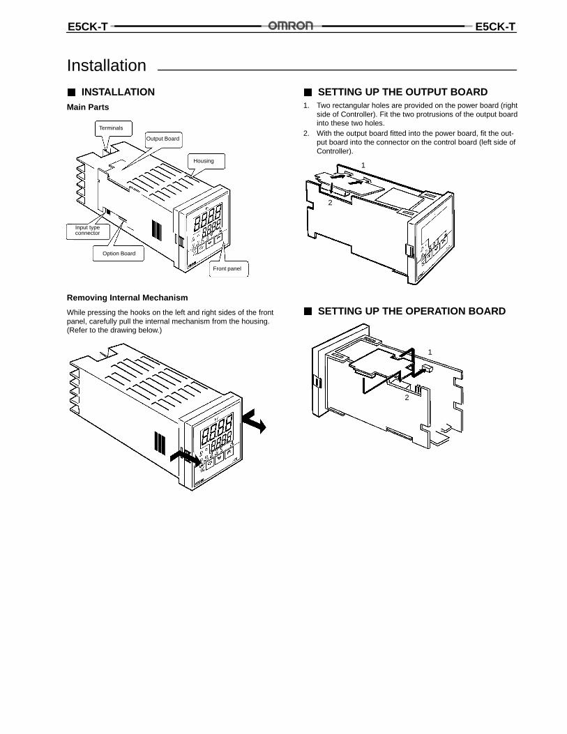
Installation
INSTALLATIONMain Parts
Terminals
Output Board
Housing
Front panel
Option Board
Input typeconnector
Removing Internal Mechanism
While pressing the hooks on the left and right sides of the frontpanel, carefully pull the internal mechanism from the housing.(Refer to the drawing below.)
SETTING UP THE OUTPUT BOARD1. Two rectangular holes are provided on the power board (right
side of Controller). Fit the two protrusions of the output boardinto these two holes.
2. With the output board fitted into the power board, fit the out-put board into the connector on the control board (left side ofController).
1
2
SETTING UP THE OPERATION BOARD
1
2
E5CK-T E5CK-T
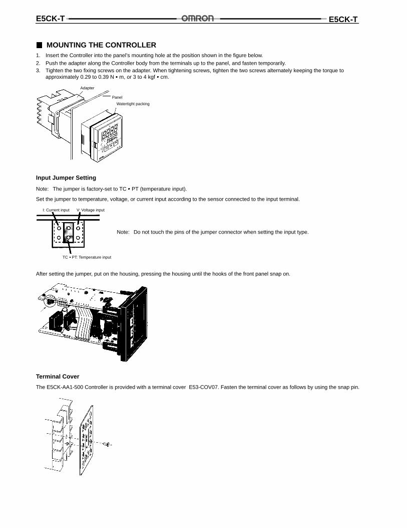
MOUNTING THE CONTROLLER1. Insert the Controller into the panel’s mounting hole at the position shown in the figure below.
2. Push the adapter along the Controller body from the terminals up to the panel, and fasten temporarily.3. Tighten the two fixing screws on the adapter. When tightening screws, tighten the two screws alternately keeping the torque to
approximately 0.29 to 0.39 N m, or 3 to 4 kgf cm.
Adapter
Panel
Watertight packing
Input Jumper Setting
Note: The jumper is factory-set to TC PT (temperature input).
Set the jumper to temperature, voltage, or current input according to the sensor connected to the input terminal.
I: Current input V: Voltage input
TC PT: Temperature input
Note: Do not touch the pins of the jumper connector when setting the input type.
After setting the jumper, put on the housing, pressing the housing until the hooks of the front panel snap on.
Terminal Cover
The E5CK-AA1-500 Controller is provided with a terminal cover E53-COV07. Fasten the terminal cover as follows by using the snap pin.
E5CK-T E5CK-T
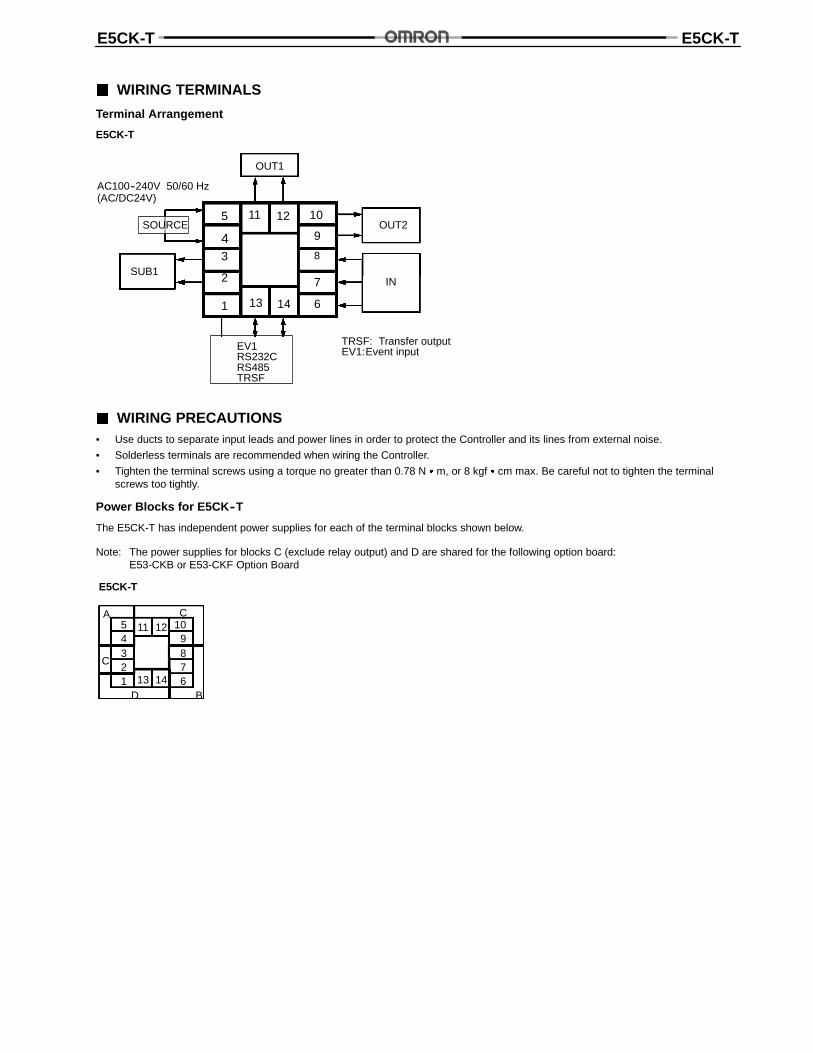
WIRING TERMINALS
Terminal Arrangement
E5CK-T
5
43
2
1
10
9
8
7
613 14
11 12
OUT1
OUT2
SUB1IN
SOURCE
EV1RS232CRS485TRSF
TRSF: Transfer outputEV1:Event input
AC100--240V 50/60 Hz(AC/DC24V)
WIRING PRECAUTIONS• Use ducts to separate input leads and power lines in order to protect the Controller and its lines from external noise.
• Solderless terminals are recommended when wiring the Controller.
• Tighten the terminal screws using a torque no greater than 0.78 N m, or 8 kgf cm max. Be careful not to tighten the terminalscrews too tightly.
Power Blocks for E5CK--T
The E5CK-T has independent power supplies for each of the terminal blocks shown below.
Note: The power supplies for blocks C (exclude relay output) and D are shared for the following option board:E53-CKB or E53-CKF Option Board
E5CK-T
A C54321
109876
C
D B
11 12
13 14
E5CK-T E5CK-T
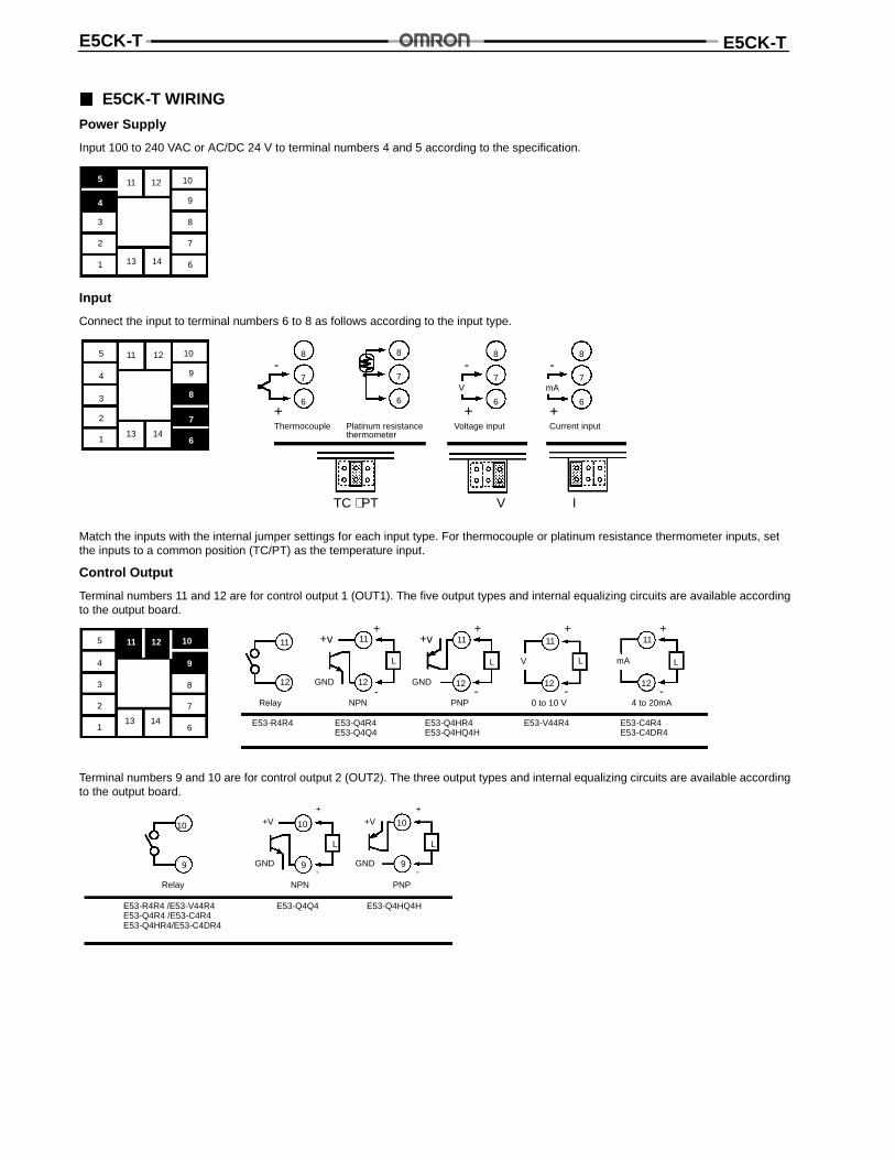
E5CK-T WIRING
Power Supply
Input 100 to 240 VAC or AC/DC 24 V to terminal numbers 4 and 5 according to the specification.
5
4
3
2
1
10
9
8
7
613 14
11 12
Input
Connect the input to terminal numbers 6 to 8 as follows according to the input type.
8
7
6
8
7
6
8
7
6
8
7
6
-
+
-
+
-
+
V mA
TC ⋅ PT V I
Thermocouple Platinum resistancethermometer
Voltage input Current input
5
4
3
2
1
10
9
8
7
613 14
11 12
Match the inputs with the internal jumper settings for each input type. For thermocouple or platinum resistance thermometer inputs, setthe inputs to a common position (TC/PT) as the temperature input.
Control Output
Terminal numbers 11 and 12 are for control output 1 (OUT1). The five output types and internal equalizing circuits are available accordingto the output board.
5
4
3
2
1
10
9
8
7
613 14
11 12 11
12
11
12
L
11
12
L
11
12
L
11
12
L
E53-R4R4 E53-Q4R4E53-Q4Q4
E53-Q4HR4E53-Q4HQ4H
E53-V44R4 E53-C4R4E53-C4DR4
NPN PNP 0 to 10 V 4 to 20mA
+v+
-
+
-
+
-
+
-GND
mA
Relay
V
+v
GND
Terminal numbers 9 and 10 are for control output 2 (OUT2). The three output types and internal equalizing circuits are available accordingto the output board.
10
9
10
9
L
10
9
L
+V+
-
+
-GND
E53-Q4Q4 E53-Q4HQ4H
NPN PNP
E53-R4R4 /E53-V44R4E53-Q4R4 /E53-C4R4E53-Q4HR4/E53-C4DR4
Relay
+V
GND
E5CK-T E5CK-T
Specifications for Each Type of Output
Output type Specifications
RelayVoltage (NPN)Voltage (PNP)
3 A at 250 VAC20 mA at 12 VDC (with short-circuit protection)20 mA at 12 VDC (with short-circuit protection)
0 to 10 V4 to 20 mA
0 to 10 VDC, permissible load impedance: 1 kΩ min., resolution: approx. 2,6004 to 20 mA, permissible load impedance: 500 Ω max., resolution: approx. 2,600
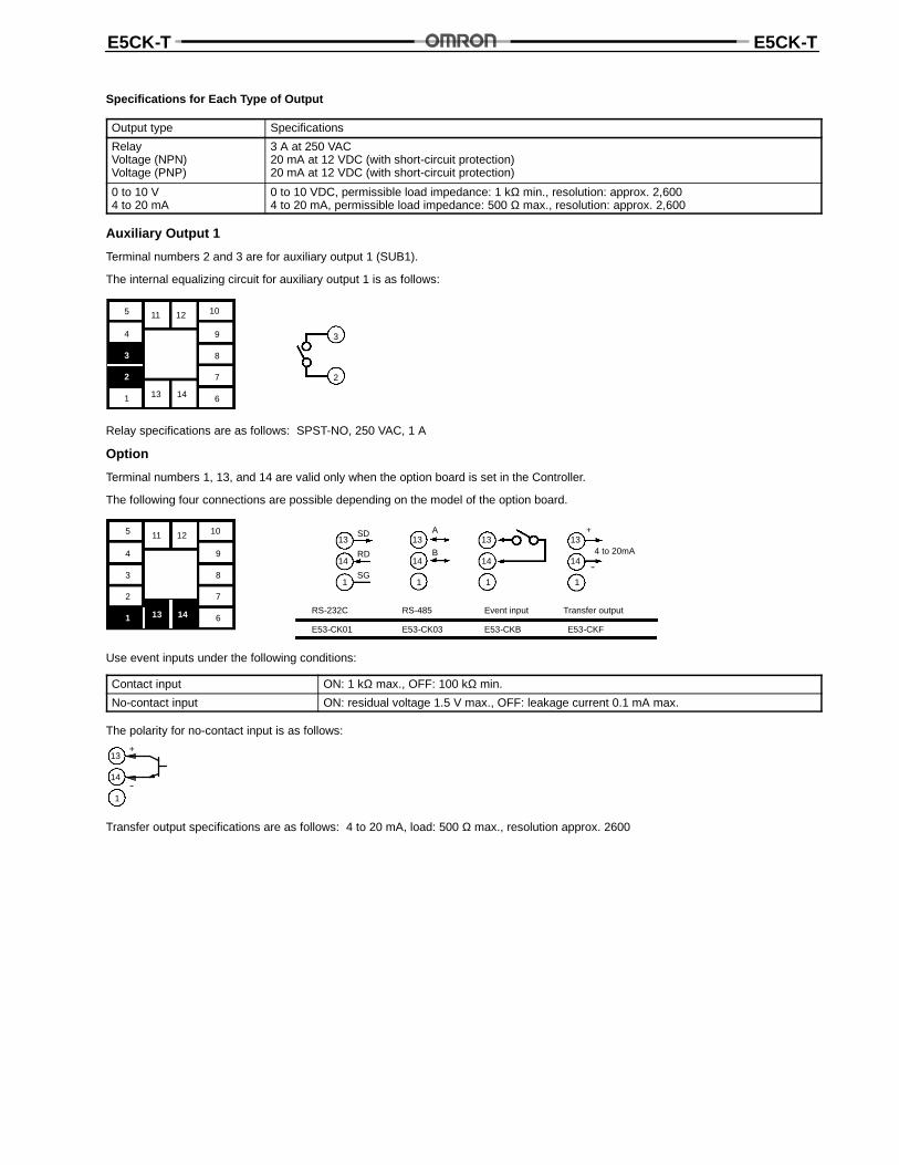
Auxiliary Output 1
Terminal numbers 2 and 3 are for auxiliary output 1 (SUB1).
The internal equalizing circuit for auxiliary output 1 is as follows:
5
4
3
2
1
10
9
8
7
613 14
11 12
3
2
Relay specifications are as follows: SPST-NO, 250 VAC, 1 A
Option
Terminal numbers 1, 13, and 14 are valid only when the option board is set in the Controller.
The following four connections are possible depending on the model of the option board.
5
4
3
2
1
10
9
8
7
613 14
11 12 13
14
1
13
14
1
13
14
1
13
14
1
SD
RD
SG
A
B
+
--
4 to 20mA
E53-CK01
RS-232C
E53-CK03
RS-485
E53-CKB E53-CKF
Event input Transfer output
Use event inputs under the following conditions:
Contact input ON: 1 kΩ max., OFF: 100 kΩ min.
No-contact input ON: residual voltage 1.5 V max., OFF: leakage current 0.1 mA max.
The polarity for no-contact input is as follows:
13
14
1
+
--
Transfer output specifications are as follows: 4 to 20 mA, load: 500 Ω max., resolution approx. 2600
E5CK-T E5CK-T
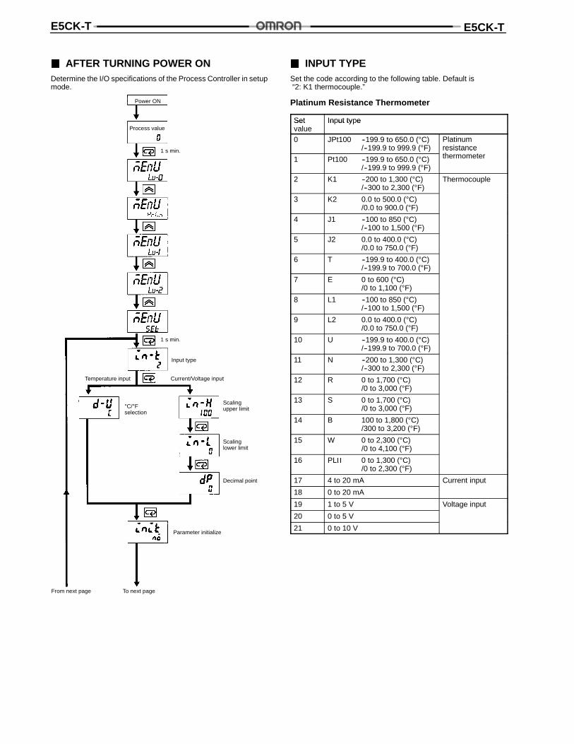
AFTER TURNING POWER ONDetermine the I/O specifications of the Process Controller in setupmode.
Power ON
Process value
1 s min.
1 s min.
Input type
Temperature input Current/Voltage input
°C/°Fselection
Scalingupper limit
Scalinglower limit
Decimal point
Parameter initialize
From next page To next page
INPUT TYPESet the code according to the following table. Default is“2: K1 thermocouple.”
Platinum Resistance Thermometer
Set Input typeSetvalue
In ut ty e
0 JPt100 --199.9 to 650.0 (°C)/--199.9 to 999.9 (°F)
Platinumresistanceh1 Pt100 --199.9 to 650.0 (°C)
/--199.9 to 999.9 (°F)
resistancethermometer
2 K1 --200 to 1,300 (°C)/--300 to 2,300 (°F)
Thermocouple
3 K2 0.0 to 500.0 (°C)/0.0 to 900.0 (°F)
4 J1 --100 to 850 (°C)/--100 to 1,500 (°F)
5 J2 0.0 to 400.0 (°C)/0.0 to 750.0 (°F)
6 T --199.9 to 400.0 (°C)/--199.9 to 700.0 (°F)
7 E 0 to 600 (°C)/0 to 1,100 (°F)
8 L1 --100 to 850 (°C)/--100 to 1,500 (°F)
9 L2 0.0 to 400.0 (°C)/0.0 to 750.0 (°F)
10 U --199.9 to 400.0 (°C)/--199.9 to 700.0 (°F)
11 N --200 to 1,300 (°C)/--300 to 2,300 (°F)
12 R 0 to 1,700 (°C)/0 to 3,000 (°F)
13 S 0 to 1,700 (°C)/0 to 3,000 (°F)
14 B 100 to 1,800 (°C)/300 to 3,200 (°F)
15 W 0 to 2,300 (°C)/0 to 4,100 (°F)
16 PL 0 to 1,300 (°C)/0 to 2,300 (°F)
17 4 to 20 mA Current input
18 0 to 20 mA
19 1 to 5 V Voltage input
20 0 to 5 V
21 0 to 10 V
E5CK-T E5CK-T
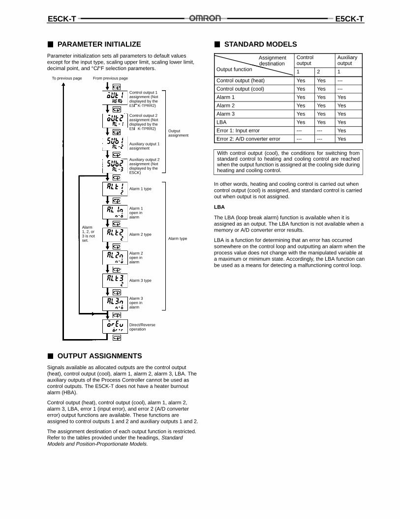
PARAMETER INITIALIZE
Parameter initialization sets all parameters to default valuesexcept for the input type, scaling upper limit, scaling lower limit,decimal point, and °C/°F selection parameters.
To previous page From previous page
Control output 1assignment (Notdisplayed by theE5K-TPRR2)
Control output 2assignment (Notdisplayed by theE5K-TPRR2)
Auxiliary output 1assignment
Outputassignment
Auxiliary output 2assignment (Notdisplayed by theE5CK)
Alarm 1 type
Alarm 1open inalarm
Alarm 2 typeAlarm type
Alarm 2open inalarm
Alarm1, 2, or3 is notset.
Alarm 3 type
Alarm 3open inalarm
Direct/Reverseoperation
OUTPUT ASSIGNMENTS
Signals available as allocated outputs are the control output(heat), control output (cool), alarm 1, alarm 2, alarm 3, LBA. Theauxiliary outputs of the Process Controller cannot be used ascontrol outputs. The E5CK-T does not have a heater burnoutalarm (HBA).
Control output (heat), control output (cool), alarm 1, alarm 2,alarm 3, LBA, error 1 (input error), and error 2 (A/D convertererror) output functions are available. These functions areassigned to control outputs 1 and 2 and auxiliary outputs 1 and 2.
The assignment destination of each output function is restricted.Refer to the tables provided under the headings, StandardModels and Position-Proportionate Models.
STANDARD MODELS
Assignmentdestination
O f i
Controloutput
Auxiliaryoutputdestination
Output function 1 2 1
Control output (heat) Yes Yes ---
Control output (cool) Yes Yes ---
Alarm 1 Yes Yes Yes
Alarm 2 Yes Yes Yes
Alarm 3 Yes Yes Yes
LBA Yes Yes Yes
Error 1: Input error --- --- Yes
Error 2: A/D converter error --- --- Yes
With control output (cool), the conditions for switching fromstandard control to heating and cooling control are reachedwhen the output function is assigned at the cooling side duringheating and cooling control.
In other words, heating and cooling control is carried out whencontrol output (cool) is assigned, and standard control is carriedout when output is not assigned.
LBA
The LBA (loop break alarm) function is available when it isassigned as an output. The LBA function is not available when amemory or A/D converter error results.
LBA is a function for determining that an error has occurredsomewhere on the control loop and outputting an alarm when theprocess value does not change with the manipulated variable ata maximum or minimum state. Accordingly, the LBA function canbe used as a means for detecting a malfunctioning control loop.
E5CK-T E5CK-T
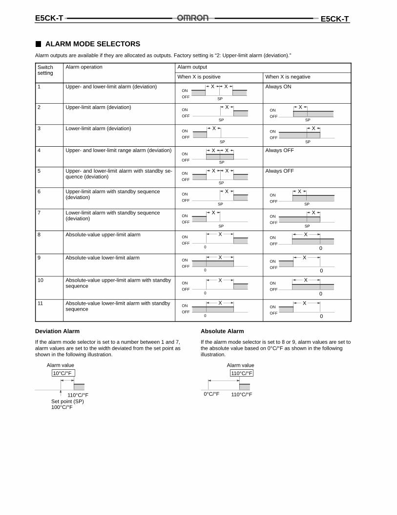
ALARM MODE SELECTORS
Alarm outputs are available if they are allocated as outputs. Factory setting is “2: Upper-limit alarm (deviation).”
Switchsetting
Alarm operation Alarm outputsetting
When X is positive When X is negative
1 Upper- and lower-limit alarm (deviation) X XON
OFF SP
Always ON
2 Upper-limit alarm (deviation) X
SP
ON
OFF
X
SP
ON
OFF
3 Lower-limit alarm (deviation) X
SP
ON
OFF
X
SP
ON
OFF
4 Upper- and lower-limit range alarm (deviation) X X
SP
ON
OFF
Always OFF
5 Upper- and lower-limit alarm with standby se-quence (deviation)
X X
SP
ON
OFF
Always OFF
6 Upper-limit alarm with standby sequence(deviation)
X
SP
ON
OFF
X
SP
ON
OFF
7 Lower-limit alarm with standby sequence(deviation)
X
SP
ON
OFF
X
SP
ON
OFF
8 Absolute-value upper-limit alarm X
0
ON
OFF0
XON
OFF
9 Absolute-value lower-limit alarm X
0
ON
OFF0
XON
OFF
10 Absolute-value upper-limit alarm with standbysequence
X
0
ON
OFF0
XON
OFF
11 Absolute-value lower-limit alarm with standbysequence
X
0
ON
OFF0
XON
OFF
Deviation Alarm
If the alarm mode selector is set to a number between 1 and 7,alarm values are set to the width deviated from the set point asshown in the following illustration.
Set point (SP)100°C/°F
Alarm value
10°C/°F
110°C/°F
Absolute Alarm
If the alarm mode selector is set to 8 or 9, alarm values are set tothe absolute value based on 0°C/°F as shown in the followingillustration.
0°C/°F
Alarm value
110°C/°F
110°C/°F
E5CK-T E5CK-T
CLOSE IN ALARM/OPEN IN ALARM
When the Controller is set to “close in alarm,” the status of the alarm output function is output as it is. When set to “open in alarm,”the status of the alarm output function is output inverted.
Condition Alarm Output Output LED
Close in alarm ON ON Lit
OFF OFF Not lit
Open in alarm ON OFF Lit
OFF ON Not lit
Alarm type and close in alarm (normally open)/open in alarm (normally close) can be set independently from each alarm.
Close in alarm/Open in alarm is set in the “alarm 1 to 3 open in alarm” parameters (setup mode).Factory setting is “close in alarm” [ ].
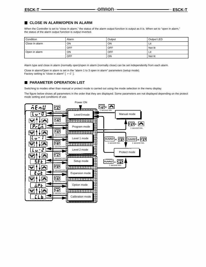
PARAMETER OPERATION LIST
Switching to modes other than manual or protect mode is carried out using the mode selection in the menu display.
The figure below shows all parameters in the order that they are displayed. Some parameters are not displayed depending on the protectmode setting and conditions of use.
Power ON
Level 0 mode
Level 1 mode
Level 2 mode
Setup mode
Expansion mode
Option mode
Calibration mode
1 second min.
Program mode
Protect mode
Manual mode
1 second min.
1 second min. 1 second min.
1 second min.
1 second min.
1 second min.
1 second min.
1 second min.
1 second min.
1 second min.
1 second min.
1 second min.
E5CK-T E5CK-T
PARAMETERS AND MENUS
All functions selected with the Controller in setup or expansion mode or all optional functions of the Process Controller may not bedisplayed.
Note: All references to Heater Burnout Alarm Function and “position-proportional” apply only to E5EK/AK-T and are not applicable toE5CK-T.
Protect Mode
The protect function is for preventing unwanted modification of parameters and switching between run and reset operation or autoand manual operation.
Manual Mode
In this mode, the Controller can be switched to manual operation. The manipulated variable can be manipulated manually only in thismode.
Level 0 Mode
Set the Controller to this mode during normal operation. In this mode, you can change the set point and pattern during operation, andexecute step operation (e.g. advance). You can only monitor (not change) the process value, step No., standby time, pattern elapsingtime, pattern execution count, and manipulated variable.
Program Mode
This is the programming mode. In this mode, you can set the number of steps used in each pattern, pattern execution count, alarmvalues, set points for each step, step time, and time signals for two steps.
Level 1 Mode
This is the main mode for adjusting control. In this mode, you can execute AT (auto-tuning), set up the control period, change PIDparameters, and set alarm values.
Level 2 Mode
This is the auxiliary mode for adjusting control. In this mode, you can set the parameters for limiting the manipulated variable, switchbetween the remote and local modes, and set the loop break alarm (LBA), alarm hysteresis, and the digital filter value of inputs.
Setup Mode
This is the mode for setting the basic specifications. In this mode, you can set parameters that must be checked or set before anoperation such as the input type, scaling, output assignments, and direct/reverse operation.
Expansion Mode
This is the mode for setting expanded functions. In this mode, you can set SP setting limiter, switching between advanced PID controlor ON/OFF control, program time unit, selection of step time/rate of rise, time unit of ramp rise rate, and the time for automatic returnto the monitoring display.
Option Mode
This is the mode for setting optional functions. You can select this mode only when an option board is mounted in the Controller. Inthis mode, you can set the communications conditions, transfer output and event input parameters to match the type of option boardmounted in the Controller.
Calibration Mode
This mode is provided so that the user can calibrate inputs and output. When calibrating input, the selected input type is calibrated.Whereas, transfer output can be calibrated only when the communications board (E53-CKF) is set in the Controller.
E5CK-T E5CK-T
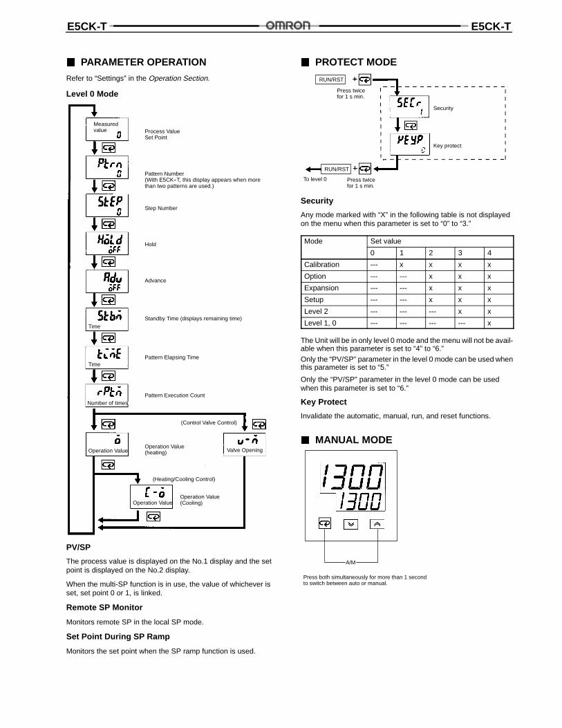
PARAMETER OPERATION
Refer to “Settings” in the Operation Section.
Level 0 Mode
Process ValueSet Point
Pattern Number(With E5CK--T, this display appears when morethan two patterns are used.)
Step Number
Hold
Advance
Standby Time (displays remaining time)
Pattern Elapsing Time
Pattern Execution Count
Operation Value(heating)
(Control Valve Control)
(Heating/Cooling Control)
Operation Value(Cooling)
Operation Value Valve Opening
Operation Value
Time
Time
Number of times
Measuredvalue
PV/SP
The process value is displayed on the No.1 display and the setpoint is displayed on the No.2 display.
When the multi-SP function is in use, the value of whichever isset, set point 0 or 1, is linked.
Remote SP Monitor
Monitors remote SP in the local SP mode.
Set Point During SP Ramp
Monitors the set point when the SP ramp function is used.
PROTECT MODE
Press twicefor 1 s min.
Security
Key protect
To level 0 Press twicefor 1 s min.
RUN/RST
RUN/RST
Security
Any mode marked with “X” in the following table is not displayedon the menu when this parameter is set to “0” to “3.”
Mode Set value
0 1 2 3 4
Calibration --- x x x x
Option --- --- x x x
Expansion --- --- x x x
Setup --- --- x x x
Level 2 --- --- --- x x
Level 1, 0 --- --- --- --- x
The Unit will be in only level 0 mode and the menu will not be avail-able when this parameter is set to “4” to “6.”
Only the “PV/SP” parameter in the level 0 mode can be used whenthis parameter is set to “5.”
Only the “PV/SP” parameter in the level 0 mode can be usedwhen this parameter is set to “6.”
Key Protect
Invalidate the automatic, manual, run, and reset functions.
MANUAL MODE
A/M
Press both simultaneously for more than 1 secondto switch between auto or manual.
E5CK-T E5CK-T
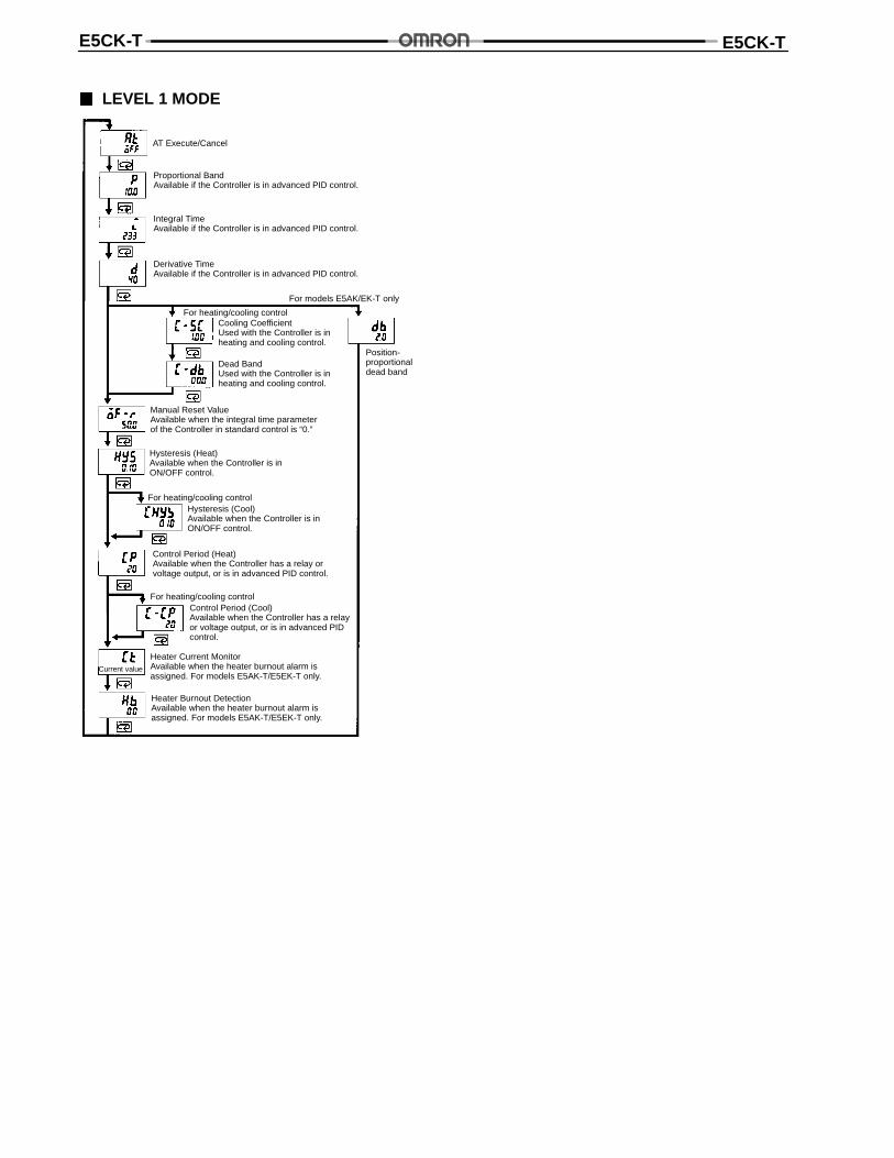
LEVEL 1 MODE
AT Execute/Cancel
Proportional BandAvailable if the Controller is in advanced PID control.
Integral TimeAvailable if the Controller is in advanced PID control.
Derivative TimeAvailable if the Controller is in advanced PID control.
For heating/cooling control
For models E5AK/EK-T only
Cooling CoefficientUsed with the Controller is inheating and cooling control.
Dead BandUsed with the Controller is inheating and cooling control.
Manual Reset ValueAvailable when the integral time parameterof the Controller in standard control is “0.”
Hysteresis (Heat)Available when the Controller is inON/OFF control.
For heating/cooling controlHysteresis (Cool)Available when the Controller is inON/OFF control.
Control Period (Heat)Available when the Controller has a relay orvoltage output, or is in advanced PID control.
For heating/cooling controlControl Period (Cool)Available when the Controller has a relayor voltage output, or is in advanced PIDcontrol.
Current value
Heater Current MonitorAvailable when the heater burnout alarm isassigned. For models E5AK-T/E5EK-T only.
Heater Burnout DetectionAvailable when the heater burnout alarm isassigned. For models E5AK-T/E5EK-T only.
Position-proportionaldead band
E5CK-T E5CK-T
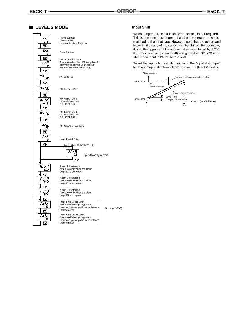
LEVEL 2 MODE
Remote/LocalUsed for thecommunications function.
LBA Detection TimeAvailable when the LBA (loop breakalarm) is assigned as an output.For models E5AK/EK-T only.
MV at Reset
MV at PV Error
MV Upper LimitUnavailable to theE5K-TPRR2.
MV Lower LimitUnavailable to theE5K-TPRR2.
MV Change Rate Limit
Input Digital Filter
Alarm 1 HysteresisAvailable only when the alarmoutput 1 is assigned.
Alarm 2 HysteresisAvailable only when the alarmoutput 2 is assigned.
Alarm 3 HysteresisAvailable only when the alarmoutput 3 is assigned.
Input Shift Upper LimitAvailable if the input type is athermocouple or platinum resistancethermometer.
Input Shift Lower LimitAvailable if the input type is athermocouple or platinum resistancethermometer.
(See Input Shift)
For models E5AK/EK-T only
Open/Close hysteresis
Standby time
Input Shift
Temperature
Upper limit
Upper-limit compensation value
Aftercompensation
Before compensation
Lower limitLower-limitcompensation value
Input (% of full scale)
When temperature input is selected, scaling is not required.This is because input is treated as the “temperature” as it ismatched to the input type. However, note that the upper- andlower-limit values of the sensor can be shifted. For example,if both the upper- and lower-limit values are shifted by 1.2°C,the process value (before shift) is regarded as 201.2°C aftershift when input is 200°C before shift.
To set the input shift, set shift values in the “input shift upperlimit” and “input shift lower limit” parameters (level 2 mode).
E5CK-T E5CK-T
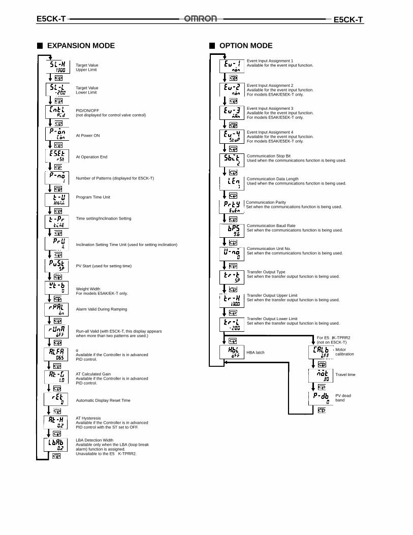
EXPANSION MODE
Target ValueUpper Limit
Target ValueLower Limit
PID/ON/OFF(not displayed for control valve control)
αAvailable if the Controller is in advancedPID control.
AT Calculated GainAvailable if the Controller is in advancedPID control.
AT HysteresisAvailable if the Controller is in advancedPID control with the ST set to OFF.
LBA Detection WidthAvailable only when the LBA (loop breakalarm) function is assigned.Unavailable to the E5K-TPRR2.
At Power ON
At Operation End
Automatic Display Reset Time
Number of Patterns (displayed for E5CK-T)
Program Time Unit
Time setting/Inclination Setting
Inclination Setting Time Unit (used for setting inclination)
PV Start (used for setting time)
Weight WidthFor models E5AK/EK-T only.
Alarm Valid During Ramping
Run-all Valid (with E5CK-T, this display appearswhen more than two patterns are used.)
OPTION MODE
Event Input Assignment 1Available for the event input function.
Event Input Assignment 2Available for the event input function.For models E5AK/E5EK-T only.
Event Input Assignment 3Available for the event input function.For models E5AK/E5EK-T only.
Event Input Assignment 4Available for the event input function.For models E5AK/E5EK-T only.
Communication Stop BitUsed when the communications function is being used.
Communication Data LengthUsed when the communications function is being used.
Communication ParitySet when the communications function is being used.
Communication Baud RateSet when the communications function is being used.
Communication Unit No.Set when the communications function is being used.
Transfer Output TypeSet when the transfer output function is being used.
Transfer Output Upper LimitSet when the transfer output function is being used.
Transfer Output Lower LimitSet when the transfer output function is being used.
Motorcalibration
Travel time
PV deadband
HBA latch
For E5K-TPRR2(not on E5CK-T)
E5CK-T E5CK-T
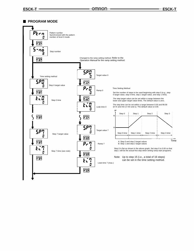
PROGRAM MODE
Pattern numberSynchronized with the patternnumber of level 0 mode.
Step number
Changed to the ramp setting method. Refer to theOperation Manual for the ramp setting method.
Time setting methodTarget value 0
Step 0 target value
Ramp 0
Step 0 time
Leak time 0
Target value 7
Step 7 target value
Ramp 7
Step 7 time (see note)
Leak time 7 (max.)
Time Setting Method
Set the number of steps to be used beginning with step 0 (e.g., step0 target value, step 0 time, step 1 target value, and step 1 time).
The step target value can be set within a range between thelower and upper target value limits. The default value is zero.
The step time can be set within a range between 0.00 and 99.59(in hr and min or min and s). The default value is 0.00.
Step 0 Step 1 Step 3Step 2
Step 0 time Step 1 time Step 2 time Step 3 time
A: Step 0 and step 3 target valuesB: Step 1 and step 2 target values
Time
Step 0 is flat as shown in the above graph. Set step 0 to 0.00 so thatstep 1 will be the actual first step when writing ramp-start programs.
Note: Up to step 15 (i.e., a total of 16 steps)can be set in the time setting method.
E5CK-T E5CK-T
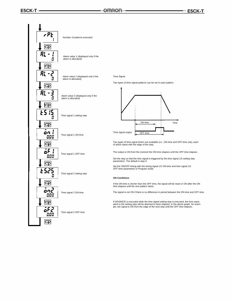
Time signal 1 setting step
Time signal 1 ON time
Time signal 1 OFF time
Time signal 2 setting step
Time signal 2 ON time
Time signal 2 OFF time
Time Signal
Two types of time signal patterns can be set in each pattern.
Time signal output
ON time Time
OFF time
Two types of time signal timers are available (i.e., ON-time and OFF-time use), eachof which starts with the edge of the step.
The output is ON from the moment the ON time elapses until the OFF time elapses.
Set the step so that the time signal is triggered by the time signal 1/2 setting stepparameters. The default is step 0.
Set the ON/OFF timing with the timing signal 1/2 ON-time and time signal 1/2OFF-time parameters in Program mode.
ON Conditions
If the ON time is shorter than the OFF time, the signal will be reset or ON after the ONtime elapses until the next pattern starts.
The signal is not ON if there is no difference in period between the ON time and OFF time.
If ADVANCE is executed while the time signal setting step is executed, the time equiv-alent to the setting step will be deemed to have elapsed. In the above graph, for exam-ple, the signal is ON from the edge of the next step until the OFF time elapses.
Number of patterns executed
Alarm value 1 (displayed only if thealarm is allocated)
Alarm value 2 (displayed only if thealarm is allocated)
Alarm value 3 (displayed only if thealarm is allocated)
E5CK-T E5CK-T
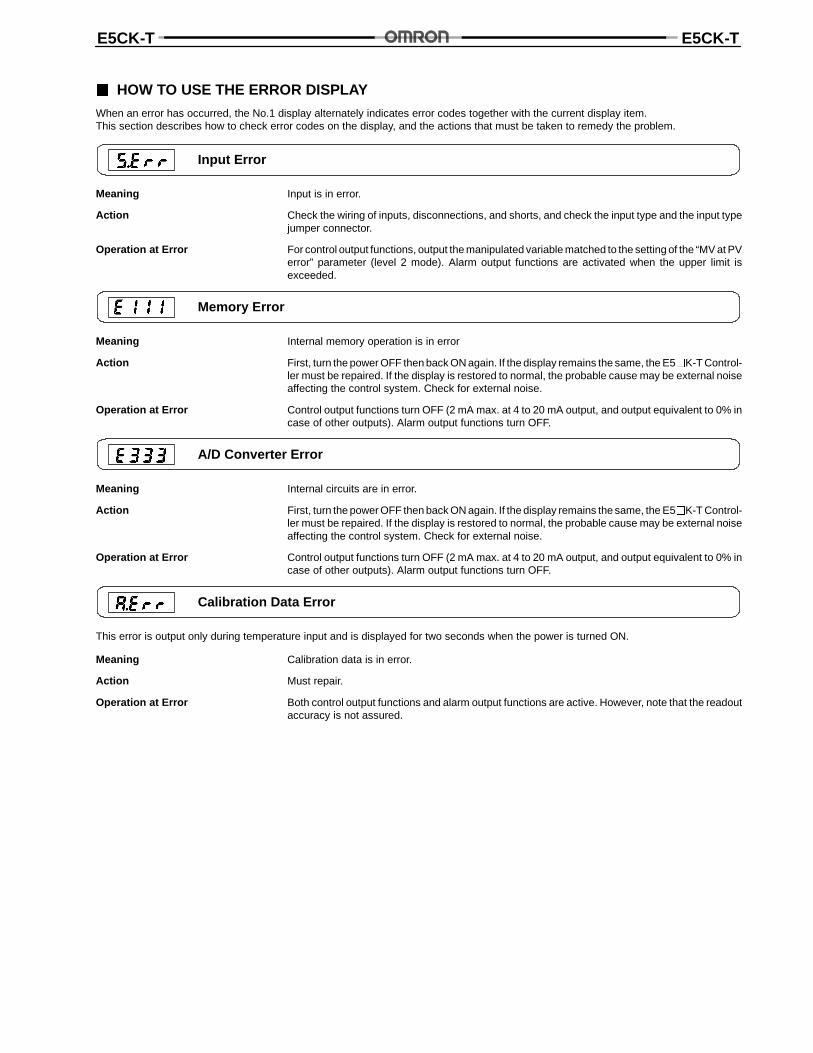
HOW TO USE THE ERROR DISPLAY
When an error has occurred, the No.1 display alternately indicates error codes together with the current display item.This section describes how to check error codes on the display, and the actions that must be taken to remedy the problem.
Input Error
Meaning Input is in error.
Action Check the wiring of inputs, disconnections, and shorts, and check the input type and the input typejumper connector.
Operation at Error For control output functions, output the manipulated variable matched to the setting of the “MV at PVerror” parameter (level 2 mode). Alarm output functions are activated when the upper limit isexceeded.
Memory Error
Meaning Internal memory operation is in error
Action First, turn the power OFF then back ON again. If the display remains the same, the E5K-T Control-ler must be repaired. If the display is restored to normal, the probable cause may be external noiseaffecting the control system. Check for external noise.
Operation at Error Control output functions turn OFF (2 mA max. at 4 to 20 mA output, and output equivalent to 0% incase of other outputs). Alarm output functions turn OFF.
A/D Converter Error
Meaning Internal circuits are in error.
Action First, turn the power OFF then back ON again. If the display remains the same, the E5K-T Control-ler must be repaired. If the display is restored to normal, the probable cause may be external noiseaffecting the control system. Check for external noise.
Operation at Error Control output functions turn OFF (2 mA max. at 4 to 20 mA output, and output equivalent to 0% incase of other outputs). Alarm output functions turn OFF.
Calibration Data Error
This error is output only during temperature input and is displayed for two seconds when the power is turned ON.
Meaning Calibration data is in error.
Action Must repair.
Operation at Error Both control output functions and alarm output functions are active. However, note that the readoutaccuracy is not assured.
E5CK-T E5CK-T
Display Range Over
Meaning Though not an error, this is displayed when the process value exceeds the display range when thecontrol range (setting range ±10%) is larger than the display range (--1999 to 9999).
• When less than “--1999”
• When greater than “9999”
Operation Control continues, allowing normal operation.
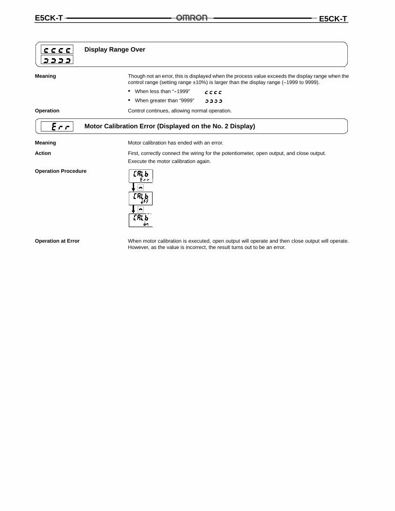
Motor Calibration Error (Displayed on the No. 2 Display)
Meaning Motor calibration has ended with an error.
Action First, correctly connect the wiring for the potentiometer, open output, and close output.
Execute the motor calibration again.
Operation Procedure
Operation at Error When motor calibration is executed, open output will operate and then close output will operate.However, as the value is incorrect, the result turns out to be an error.
E5CK-T E5CK-T
Precautions
OPERATING ENVIRONMENT• Operate the Controller within the rated ambient operating
temperature, ambient operating humidity, and storage tem-perature ranges.
• Use the Controller according to the vibration resistance,shock resistance, and enclosure ratings.
• Do not install the Controller in places with corrosive gas orexcessive dust.
• Do not install the Controller near machines generating high-frequency noise.
MOUNTING• The dimensions of the Controller conform to DIN 43700.
• Recommended panel thickness is 1 to 8 mm.
• Mount the Unit horizontally.
CONNECTION• To reduce inductive noise influence, the lead wires connect-
ing the input type to the Controller must be separated fromthe power lines and load lines.
• Use the specified compensating conductors for thermocou-ples. Use lead wires having a small resistance for platinumresistance thermometers.
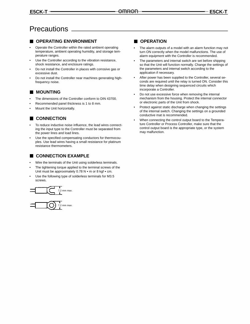
CONNECTION EXAMPLE• Wire the terminals of the Unit using solderless terminals.
• The tightening torque applied to the terminal screws of theUnit must be approximately 0.78 N m or 8 kgf cm.
• Use the following type of solderless terminals for M3.5screws.
7.2 mm max.
7.2 mm max.
OPERATION• The alarm outputs of a model with an alarm function may not
turn ON correctly when the model malfunctions. The use ofalarm equipment with the Controller is recommended.
• The parameters and internal switch are set before shippingso that the Unit will function normally. Change the settings ofthe parameters and internal switch according to theapplication if necessary.
• After power has been supplied to the Controller, several se-conds are required until the relay is turned ON. Consider thistime delay when designing sequenced circuits whichincorporate a Controller.
• Do not use excessive force when removing the internalmechanism from the housing. Protect the internal connectoror electronic parts of the Unit from shock.
• Protect against static discharge when changing the settingsof the internal switch. Changing the settings on a groundedconductive mat is recommended.
• When connecting the control output board to the Tempera-ture Controller or Process Controller, make sure that thecontrol output board is the appropriate type, or the systemmay malfunction.
E5CK-T E5CK-T
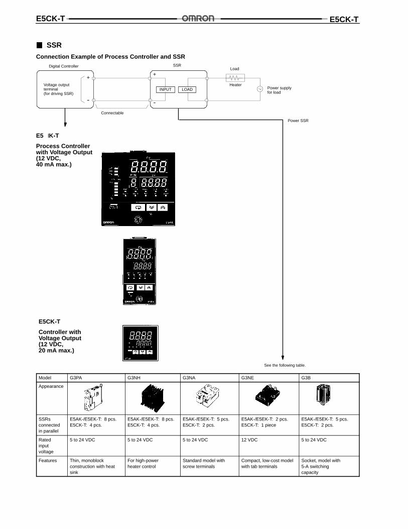
SSR
Connection Example of Process Controller and SSR
+
--
+
--
Digital Controller
Voltage outputterminal(for driving SSR)
Connectable
Load
HeaterPower supplyfor load
Power SSR
SSR
E5K-T
Process Controllerwith Voltage Output(12 VDC,40 mA max.)
See the following table.
E5CK-T
Controller withVoltage Output(12 VDC,20 mA max.)
INPUT LOAD
Model G3PA G3NH G3NA G3NE G3B
Appearance
SSRsconnectedin parallel
E5AK-/E5EK-T: 8 pcs.E5CK-T: 4 pcs.
E5AK-/E5EK-T: 8 pcs.E5CK-T: 4 pcs.
E5AK-/E5EK-T: 5 pcs.E5CK-T: 2 pcs.
E5AK-/E5EK-T: 2 pcs.E5CK-T: 1 piece
E5AK-/E5EK-T: 5 pcs.E5CK-T: 2 pcs.
Ratedinputvoltage
5 to 24 VDC 5 to 24 VDC 5 to 24 VDC 12 VDC 5 to 24 VDC
Features Thin, monoblockconstruction with heatsink
For high-powerheater control
Standard model withscrew terminals
Compact, low-cost modelwith tab terminals
Socket, model with5-A switchingcapacity

E5CK-T E5CK-T
Cat. No. GCTC12 1/99 Specifications subject to change without notice. Printed in U.S.A.
OMRON ELECTRONICS, INC.One East Commerce DriveSchaumburg, IL 60173
1-800-55-OMRON
OMRON CANADA, INC.885 Milner AvenueScarborough, Ontario M1B 5V8
416-286-6465