Embed Size (px)
Citation preview

COMMANDER 350COMMANDER 360
User Guide
Modbus™ SerialCommunications
COMMANDER 360
X
PV
SPW
360.0360.0
36OP1
MOP2
SEGPRG
COMMANDER 350
X
PV
SPW
YOP
351.0351.0
35
MST SLV R
OP1M OP2 FF

REGISTERE
D
0255
The CompanyABB Automation is an established world force in the design andmanufacture of instrumentation for industrial process control, flowmeasurement, gas and liquid analysis and environmental applications.
As a part of ABB, a world leader in process automation technology, we offercustomers application expertise, service and support worldwide.
We are committed to teamwork, high quality manufacturing, advancedtechnology and unrivalled service and support.
The quality, accuracy and performance of the Company’s products resultfrom over 100 years experience, combined with a continuous program ofinnovative design and development to incorporate the latest technology.
The NAMAS Calibration Laboratory (No. 0255) is just one of ten flowcalibration plants operated by the Company, and is indicative of ABBAutomation’s dedication to quality and accuracy.
BS EN ISO 9001
St Neots, U.K. – Cert. No. Q5907Stonehouse, U.K. – Cert. No. FM 21106
EN 29001 (ISO 9001)
Lenno, Italy – Cert. No. 9/90A
Stonehouse, U.K.
Use of Instructions
Warning.An instruction that draws attention to the risk ofinjury or death.
Caution.An instruction that draws attention to the risk ofdamage to the product, process or surroundings.
Note.Clarification of an instruction or additionalinformation.
Information.Further reference for more detailed informationor technical details.
Although Warning hazards are related to personal injury, and Caution hazards are associated with equipment orproperty damage, it must be understood that operation of damaged equipment could, under certain operationalconditions, result in degraded process system performance leading to personal injury or death. Therefore, complyfully with all Warning and Caution notices.
Information in this manual is intended only to assist our customers in the efficient operation of our equipment. Useof this manual for any other purpose is specifically prohibited and its contents are not to be reproduced in full or partwithout prior approval of Marketing Communications Department, ABB Automation.
Health and Safety
To ensure that our products are safe and without risk to health, the following points must be noted:
1. The relevant sections of these instructions must be read carefully before proceeding.
2. Warning labels on containers and packages must be observed.
3. Installation, operation, maintenance and servicing must only be carried out by suitably trained personneland in accordance with the information given.
4. Normal safety precautions must be taken to avoid the possibility of an accident occurring when operatingin conditions of high pressure and/or temperature.
5. Chemicals must be stored away from heat, protected from temperature extremes and powders kept dry.Normal safe handling procedures must be used.
6. When disposing of chemicals ensure that no two chemicals are mixed.
Safety advice concerning the use of the equipment described in this manual or any relevant hazard datasheets (where applicable) may be obtained from the Company address on the back cover, together withservicing and spares information.
ABB AUTOMATION

1
CONTENTS
Section Page
1 INTRODUCTION ..................................... 2
2 ELECTRICAL INSTALLATION .............. 32.1 Host Computer Serial
Communications ........................... 32.2 OPTO22 Boards for use with
Personal Computers ..................... 32.3 Two-wire and Four-wire
Connection .................................... 32.4 Pull-up and Pull-down
Resistors ....................................... 42.5 Termination Resistor ..................... 42.6 Serial Connections ........................ 5
3 CONFIGURATION .................................. 63.1 Accessing the Serial
Configuration Displays .................. 63.2 Setting the Serial
Transmission Parameters ............. 7
4 MODBUS PROTOCOL ........................... 84.1 Introduction ................................... 84.2 Modbus Function Codes ............... 9
5 MODBUS FUNCTIONS ........................ 105.1 Read Coil Status –
Function Code 01 ........................ 105.2 Read Holding Register –
Function Code 03 ......................... 115.3 Force Single Coil –
Function Code 05 ........................ 125.4 Preset Single Register –
Function Code 06 ........................ 135.5 Loopback Test –
Function Code 08 ........................ 145.6 Force Multiple Coils –
Function Code 15 ........................ 155.7 Write Multiple Registers –
Function Code 16 ........................ 16
6 EXCEPTION RESPONSES .................. 176.1 Examples .................................... 17
Section Page
7 ADDRESSABLE PARAMETERS ......... 187.1 Coils ............................................ 187.2 Analog Input Registers ............... 207.3 Single Loop Parameters
(Templates 1 and 2) .................... 207.4 Auto/manual Station and
Analog Backup Parameters(Templates 3 to 6) ....................... 21
7.5 Indicator and ManualLoader Station Parameters(Templates 7 and 8) .................... 21
7.6 Feedforward Parameters(Templates 9 and 10) .................. 21
7.7 Cascade Parameters(Templates 11 and 12) ................ 22
7.8 Cascade with FeedforwardParameters(Template 13) .............................. 22
7.9 Ratio Station andController Parameters(Templates 14 to 17) ................... 23
7.10 Control Monitor ........................... 237.11 Tuning Parameters ..................... 247.12 Set Point Parameters .................. 247.13 Alarm Parameters ....................... 257.14 Motorized Valve Parameters ...... 267.15 Basic Configuration ..................... 277.16 Math Blocks ................................. 287.17 Ramp/Soak Program Parameters
(COMMANDER 355 and 360Instruments Only) ....................... 29
7.18 Ramp/Soak SegmentParameters .................................. 30

2
1 INTRODUCTION
This Operating Guide describes the COMMANDER 350 and 360 series of instruments Modbus™serial data communications options and must be used in conjunction with the standard User Guide(part no. IM/C351, IM/C355 or IM/C360) supplied with the instrument.
Information.The Modbus option provides the following facilities:• Standard RS422/485 communications.• Modbus RTU protocol – for master (host computer) to slave (COMMANDER 350 or 360)
system.• Isolation from external connections to the instrument. Dielectric strength 500V d.c. for
1 minute.• Two-wire or four-wire communication.• 2400, 9600 or 19200 baud transmission rate.• Parity-checking – odd, even or none.

3
+5V
0V
1.8kΩ Pull-upResistor
1.8kΩ Pull-downResistor
Host Computer
Rx–Rx+Tx–Tx+
'A'
'A'
'B'
'B'
2021222324
C350/C360
GND
Common
Tx+/Rx+
Tx–/Rx–
2 ELECTRICAL INSTALLATION
This section describes the connection of serial data transmission cables between the master (hostcomputer) and slave COMMANDER 350 series or 360 series of instruments on a Modbus serial link.All connections other than those used for serial communication are shown in Section 5 of the relevantUser Guide.
2.1 Host Computer Serial CommunicationsAn RS422/485 communications driver must be fitted to the host computer. It is stronglyrecommended that the interface has galvanic isolation to protect the computer from lightningdamage and increase signal immunity to noise pick-up.
2.2 OPTO22 Boards for use with Personal ComputersWhere a personal computer is used as the host computer, the following OPTO22 boards arerecommended for use with the COMMANDER 350 and 360 series of instruments:
Part No. Computer TypeAC24 AT AT Bus IBM PC compatibleAC34 Microchannel IBM PC
2.3 Two-wire and Four-wire Connection – Figs. 2.1 and 2.2Modbus serial communications must be configured as either two-wire or four-wire serial links –see Figs. 2.1 and 2.2. Two-/four-wire operation must also be selected in the Configuration Mode– see Section 3.1.
Fig. 2.1 Pull-up and Pull-down Resistors (Two-wire Operation)

4
Host Computer+5V
0V
'A'
'B'
1.8kΩPull-downResistor
1.8kΩ Pull-upResistor0V
+5V
0V
'A'
'B'
1.8kΩPull-down Resistor
1.8kΩPull-upResistor
Rx+
Rx–
Tx–
Tx+
C2021222324
C350/C360
First Slave Last Slave
C
Rx+
Rx–
Tx+
Tx–
120ΩTermination Resistor
(External)
Master
GNDTx+Tx–Rx+Rx–
20
21
22
23
24
HostComputer
C
Rx+
Rx–
Tx+
Tx–
C350/C360
20
21
22
23
24
…2 ELECTRICAL INSTALLATION
2.4 Pull-up and Pull-down Resistors – Figs. 2.1 and 2.2To prevent false triggering of slaves when the master (host computer) is inactive, pull-up and pull-down resistors must be fitted to the RS422/485 interface in the host computer – see Figs. 2.1 and 2.2.
2.5 Termination Resistor – Fig. 2.3For long transmission lines, a 120Ω termination resistor must be fitted to the last slave in the chain– see Fig. 2.3.
Fig. 2.2 Pull-up and Pull-down Resistors (Four-wire Operation)
Fig. 2.3 Connecting Multiple Slaves

5
Tx+
Tx–
Rx+
Rx–
GND
OPTO22 AdaptorBoard Connections
Screen
4
5
8
9
3
Rx+
Rx–
Tx–
Tx+
C2021222324
C350/C360
2 ELECTRICAL INSTALLATION…
2.6 Serial Connections – Figs. 2.1 to 2.4
Information.• Up to 10 slaves can be connected to a single RS422 adaptor card on a PC.• Up to 32 slaves can be connected to a single RS485 adaptor card on a PC.The number of slaves can be increased if the driver's serial port permits.
Connections to the Modbus serial board must be made as shown in Figs. 2.1, 2.2 or 2.4. Connectionson links with multiple slaves must be made in parallel, as shown in Fig. 2.3. When connecting cablescreens, ensure that no 'ground loops' are introduced.
The maximum serial data transmission line length for both RS422 and RS485 systems is 1200m. The typesof cable that can be used are determined by the total line length:
Up to 6m – standard screened or twisted pair cable.
Up to 300m – twin twisted pair with overall foil screen and an integral drain wire, e.g. Belden 9502or equivalent.
Up to 1200m – twin twisted pair with separate foil screens and integral drain wires, e.g. Belden9729 or equivalent.
Fig. 2.4 OPTO22 Board Connections

6
xxxxCOdE
50AtNE
LEV2 LEV5tUNE VALV
LEV6APPL
LEVdSErL
LEV1OPEr Press
and hold
Pressand hold Set the
correctpassword
351.5
351.5
60
350.0
351.5
70
x 7x 3x 1 (•1)or
x 4 (•2)
•1 COMMANDER 351 or COMMANDER 355 with ramp/soak disabled.•2 COMMANDER 360 or COMMANDER 355 with ramp/soak enabled.
3 CONFIGURATION
Information.• Programmable baud rate – 2400, 9600 or 19200 baud.• Selectable parity – odd, even or none.• Address range – 1 to 99.
For Modbus communications to operate correctly, each COMMANDER 350 or 360 must beconfigured with the correct serial transmission parameters and assigned a unique address.
3.1 Accessing the Serial Configuration Displays
Fig. 3.1 Access to Serial Configuration Displays

7
SErLLEVdd.00
1Addrd.03
NONEPrtYd.02
0S.CFGd.01
3 CONFIGURATION
3.2 Setting the Serial Transmission Parameters
Level d – Serial Communications Configuration
Note. To select this frame from anywhere in this page,press the key for a few seconds.
Serial Configuration
0 – OFF1 – 2-wire connection, 2400 baud rate2 – 4-wire connection, 2400 baud rate3 – 2-wire connection, 9600 baud rate4 – 4-wire connection, 9600 baud rate5 – 2-wire connection, 19200 baud rate6 – 4-wire connection, 19200 baud rate
Parity
NONE
Odd
EVEN
Modbus address
[1 to 99]
Return to top of page.

8
4 MODBUS PROTOCOL
Information.• The COMMANDER 350 and 360 operate as Modbus, Remote Terminal Unit (RTU) slaves.• Parity checking – detects transmission errors in individual characters.• Cyclic redundancy checking – detects errors in the master messages and slave responses.
4.1 IntroductionModbus communication uses the master/slave principle to send messages to one or more slaves.Each slave is given a unique identity address (between 1 and 99).
A broadcast address (address zero) can be used to write to all slave devices simultaneously, usingone command. In this instance there is no slave acknowledgment.
Slaves cannot accept new messages until the current message has been processed and a reply sentto the master (maximum response time 125ms). The slave monitors the elapsed time betweenreceipt of characters. If the elapsed time without a new character is 31/2 character times, the slaveassumes the next character received is the start of a new message.
Note. Modbus RTU requires 1 start bit, 8 data bits, 1 parity bit (optional) and 1 or 2 stopbits.

9
noitcnuFedoC
eltiTnoitcnuF noitpircseD
10lioCdaeR
sutatS
.tniopgnitratscificepsamorfstniop)naelooB(etercsidevitucesnoc23otpudaeRataddenifedniatnoctonodhcihwstnioprofsorezsnruter06/053REDNAMMOCehT
.06nahtretaergsrebmuntnioproftseuqeryna*sKANdna
30gnidloHdaeR
retsigeR
ehT.retsigergnitratscificepsamorfsretsigerevitucesnoc8otpudaeRdnaataddenifedniatnoctonodhcihwstnioprofsorezsnruter06/053REDNAMMOC
.022nahtretaergsrebmuntnioproftseuqeryna*sKAN
50elgniSecroF
lioCsitniopehtfisiht*sKAN053REDNAMMOCehT.tniop)naelooB(etercsidenoetirW
.elbaetirwyltnerructon
60elgniSteserP
retsigeR
erofebretsigerehtotstimilgnitsixeynaseilppaoslaedocsihT.retsigerenoetirWtonsiretsigerehtfi*sKAN06/053REDNAMMOCehT.tnemurtsniehtniegarots
.elbaetirwyltnerruc
80 kcaBpooL .detroppussi’yreuQfonruteR‘ylnO.egassemehtohcE
51teserP
slioCelpitluMsliocehtfoynafi*sKAN06/053REDNAMMOCehT.emitataslioc23otpuetirW
.dilaverahcihwsetirwehtllatuoseirractub,elbaetirwyltnerructonera
61teserPelpitluMsretsigeR
ehT.retsigergnitratsdeificepsamorfsretsigerevitucesnocthgieotpuetirWtub,elbaetirwyltnerructonerasretsigerehtfoynafi*sKAN06/053REDNAMMOC
eulavehtotstimilgnitsixeynagniylppa,dilaverahcihwsetirwehtllatuoseirrac.tnemurtsniehtniegarotserofeb
tnemgdelwonkcAevitageN=KAN*
4 MODBUS PROTOCOL
4.2 Modbus Function CodesThe function code instructs the addressed slave which function to perform. Table 4.1 shows thefunction codes, and describes the action they initiate.
Table 4.1 Modbus Function Codes

10
sserddA noitcnuF tnuoCetyBlioCataD01sutatS
71ot
lioCataD81sutatS
52ot
dleiFkcehCrorrE)61CRC(
10 10 20 C7 C0 99 93
sserddA noitcnuFtesffOtratSlioC slioCfo.oN dleiFkcehCrorrE
)61CRC(hgiH woL hgiH woL
10 10 00 90 00 01 DE 4C
5 MODBUS FUNCTIONS
This section shows typical examples of Modbus function codes 01, 03, 05, 06, 08, 15 and 16.
5.1 Read Coil Status – Function Code 015.1.1 Read Coil Status QueryThis function obtains the ON/OFF status of logic coils used to control discrete outputs from theaddressed slave. Broadcast mode is not supported with this function code. In addition to the slaveaddress and function fields, the information field must contain the initial coil offset address (startingaddress) and the number of each location to be interrogated.
Note. The coil offset address is one less than the coil number, e.g. to start at coil 10 thestart address must be set to 09 (09H).
Example. Read 16 coils from slave (01) starting at coil 10 (alarm state 1).
5.1.2 Read Coil Status ResponseThe data is packed one bit for each coil (1 = ON, 0 = OFF). The response includes the slave address,function code, quantity of data characters, the data characters and error checking. The low order bitof the first character contains the first addressed coil and the remainder follow. For coil quantities thatare not multiples of eight, the last characters are packed with zeros at the high order end.
ExampleAlarms A3, A4, A5, A6 & A7 activeAlarms A1, A2, & A8 inactiveAlarms A3 & A4 are unacknowledgedAlarms A1, A2, A5, A6, A7 & A8 are acknowledged

11
sserddA noitcnuFtesffOretsigeR sretsigeRfo.oN dleiFkcehCrorrE
)61CRC(hgiH woL hgiH woL
10 30 00 00 00 20 4C B0
sserddA noitcnuFetyB
tnuoC
10retsigeRgnidloH 20retsigeRgnidloH kcehCrorrE)61CRC(dleiFhgiH woL hgiH woL
10 30 40 A0 E8 00 10 3D CC
5 MODBUS FUNCTIONS
5.2 Read Holding Register – Function Code 035.2.1 Read Holding Register QueryThe Read Holding Register Query obtains the contents of up to eight holding registers in theaddressed slave.
Note. The data start register must contain the offset address of the first register to beaccessed, e.g. to start at register 1 the data start register must contain 00 (00H).
Broadcast mode is not supported by Function Code 03.
Example. Read two holding registers from slave (01) starting at holding address 01 (processvariable input).
5.2.2 Read Holding Register ResponseThe addressed slave responds with its address and function code, followed by the information field.The information field contains one byte describing the quantity of data bytes to be returned. Twobytes are used to return each register requested, the first byte containing the high order bits and thesecond the low order bits.
ExamplePV input (two registers) – 270PV decimal places – 1

12
sserddA noitcnuFtesffOtratSlioC eulaVataD dleiFkcehCrorrE
)61CRC(hgiH woL hgiH woL
10 50 00 62 FF 00 D6 1F
sserddA noitcnuFtesffOtratSlioC eulaVataD dleiFkcehCrorrE
)61CRC(hgiH woL hgiH woL
10 50 00 62 FF 00 D6 1F
…5 MODBUS FUNCTIONS
5.3 Force Single Coil – Function Code 055.3.1 Force Single Coil QueryThis message forces a single coil either ON or OFF. The data value 65,280 (FF00 HEX) sets the coilON and the value zero turns it OFF. All other values are illegal and have no effect on coil status.
Note. To write to a coil its offset address (one less than the coil number) must be used, e.g.to write to coil 39, the coil address 38 (26H) is transmitted.
The use of slave address zero (broadcast mode) forces all attached slaves to modify the desired coil.
Example. Switch ON coil address 39 (auto/manual state) in slave 01.
5.3.2 Force Single Coil ResponseThe response is confirmation of the query after the coil state has been altered.
Example

13
sserddA noitcnuFtesffOretsigeR eulaVataD dleiFkcehCrorrE
)61CRC(hgiH woL hgiH woL
10 60 00 76 10 4F 83 20
sserddA noitcnuFtesffOretsigeR eulaVataD dleiFkcehCrorrE
)61CRC(hgiH woL hgiH woL
10 60 00 76 10 4F 83 20
5 MODBUS FUNCTIONS…
5.4 Preset Single Register – Function Code 065.4.1 Preset Single Register QueryThe Preset Single Register Query modifies the contents of a holding register.
Note. Function codes 05, 06, 15 and 16 are the only messages that are recognized asvalid for broadcast.
Example. Write the value 500 to holding register address 104 (proportional band 1 – heat) in slave 01.
Note. To write to a register, its offset address (one less than the register number) must beused, e.g. to write to register 104, the offset address 103 (67H) is transmitted.
5.4.2 Preset Single Register ResponseThe response to a Preset Single Register Response request is to retransmit the query message afterthe register has been altered.
Example
14
sserddA noitcnuFedoCcitsongaiDataD
*ataD *ataDdleiFkcehCrorrE
)61CRC(hgiH woL
10 80 00 00 5A 73 AD D8
sserddA noitcnuFedoCcitsongaiDataD
*ataD *ataDdleiFkcehCrorrE
)61CRC(hgiH woL
10 80 00 00 5A 73 AD D8
…5 MODBUS FUNCTIONS
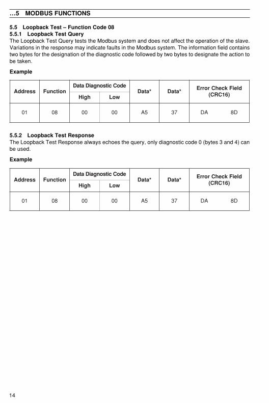
5.5 Loopback Test – Function Code 085.5.1 Loopback Test QueryThe Loopback Test Query tests the Modbus system and does not affect the operation of the slave.Variations in the response may indicate faults in the Modbus system. The information field containstwo bytes for the designation of the diagnostic code followed by two bytes to designate the action tobe taken.
Example
5.5.2 Loopback Test ResponseThe Loopback Test Response always echoes the query, only diagnostic code 0 (bytes 3 and 4) canbe used.
Example

15
sserddA noitcnuFtesffOtratSlioC slioCfo.oN dleiFkcehCrorrE
)61CRC(hgiH woL hgiH woL
10 F0 00 62 00 20 53 1C
sserddA noitcnuFtesffOtratSlioC slioCforebmuN etyB
tnuoC
ataDlioCsutatS
kcehCrorrE)61CRC(dleiFhgiH woL hgiH woL
10 F0 00 62 00 20 10 10 61 09
5 MODBUS FUNCTIONS…
5.6 Force Multiple Coils – Function Code 155.6.1 Force Multiple Coils QueryThis message is used to force up to 32 coils at a time to the ON or OFF state. When used with slaveaddress zero (broadcast mode) all slave controllers force the selected coils to the state(s) specified.
Note. To write to a coil, its offset address (one less than the register number) must beused, e.g. to write to coil 39, the offset address 38 (26H) is transmitted.
Example. Force coil 39 to ON (Select manual mode) and coil 40 to OFF (Select Local Set Pointmode).
5.6.2 Force Multiple Coils ResponseThe Force Multiple Coils Response confirms slave identification, function code, starting registeraddress and quantity only.
Example

16
sserddA noitcnuFtesffOtratSretsigeR sretsigeRfo.oN dleiFkcehCrorrE
)61CRC(hgiH woL hgiH woL
10 01 00 76 00 20 AF 71
rddA tcnuF
retsigeRtesffOtratS
forebmuNsretsigeR etyB
tnuoC
gnidloH401retsigeR
gnidloH501retsigeR
kcehCrorrEdleiF
)61CRC(hgiH woL hgiH woL hgiH woL hgiH woL
10 01 00 76 00 20 40 10 4F 00 46 5F 48
5 MODBUS FUNCTIONS
5.7 Write Multiple Registers – Function Code 165.7.1 Write Multiple Registers QueryThis message is used to change the contents of up to eight holding registers at a time. When usedwith slave address zero (broadcast mode) all slave controllers load the selected registers with thecontents specified.
Note. To write to a register, its offset address (one less than the register number) must beused, e.g. to write to register 104, the offset address 103 (67H) is transmitted.
Example. Write the value 500 to the register address 104 (proportional band 1 – heat) and the value100 to the register address 105 (integral action time) in slave 01.
5.7.2 Write Multiple Registers ResponseThe Write Multiple Registers Response confirms slave identification, function code, starting registeraddress and quantity only.
Example

17
sserddA noitcnuF noitpecxEdleiFkcehCrorrE
)61CRC(
10 38 20 0C 1F
sserddA noitcnuFtesffOtratSretsigeR sretsigeRfo.oN dleiFkcehCrorrE
)61CRC(hgiH woL hgiH woL
10 30 10 B2 00 60 4B C3
noitpecxEesnopseR
edoC
noitpecxEemaNesnopseR
noitinifeDesnopseRnoitpecxE
10 noitcnuFlagellIehtnonoitcnufelbawollanatonsideviecernoitcnufegassemehT
.063/053REDNAMMOC
20ataDlagellI
sserddArofsserddaelbawollanatonsidleifatadehtniecnerefersserddaehT
.063/053REDNAMMOCeht
30 eulaVataDlagellIdesserddaehtnoelbawollatonsidleifatadehtnidecnerefereulavehT
.noitacolevals
70evitageN
tnemegdelwonkcA.demrofrepebtonnacdetseuqertsujnoitcnufehT
80ytiraPyromeM
rorrE.deviecersretcarahcehtfoeromroenonirorrenasetacidnikcehcytiraP
6 EXCEPTION RESPONSES
The exception response codes sent by the slave are shown in Table 6.1. When a slave detects oneof these errors, it sends a response message to the master consisting of slave address, functioncode, error code and error check fields.
6.1 ExamplesA Read Register Request to read holding register address 300 of Slave 01 (undefined address forSlave, beyond address limit).
The slave replies with an exception response signifying an ‘illegal data address’. To indicate that theresponse is a notification of an error, the most significant bit of the function code is set to 1.
Table 6.1 Exception Response Codes

18
.oNlioC lebaLelbairaV etirW/daeR seulaV/stimiL
10 etatsliafelbairavssecorP R;liaF=1;ssaP=0
liaFJC=3;ydaeRtoN=2
20 etatsliaftnioptesetomeR R deliaF=1
30 etatsliaf1tupnigolanA R deliaF=1
40 etatsliaf2tupnigolanA R deliaF=1
50 etatsliaf3tupnigolanA R deliaF=1
60 1rotinoMkaerBpooL R deliaF=1
70 devreseR –
01 etats1AmralA R evitcA=1
11 etats2AmralA R evitcA=1
21 etats3AmralA R evitcA=1
31 etats4AmralA R evitcA=1
41 etats5AmralA R evitcA=1
51 etats6AmralA R evitcA=1
61 etats7AmralA R evitcA=1
71 etats8AmralA R evitcA=1
81 etats1AegdelwonkcamralA R evitcA=1
91 etats2AegdelwonkcamralA R evitcA=1
02 etats3AegdelwonkcamralA R evitcA=1
12 etats4AegdelwonkcamralA R evitcA=1
22 etats5AegdelwonkcamralA R evitcA=1
32 etats6AegdelwonkcamralA R evitcA=1
42 etats7AegdelwonkcamralA R evitcA=1
52 etats8AegdelwonkcamralA R evitcA=1
72 etats1tupnilatigiD R evitcA=1
82 etats2tupnilatigiD R evitcA=1
92 etats3tupnilatigiD R evitcA=1
03 etats4tupnilatigiD R evitcA=1
13 etats1tuptuolatigiD R evitcA=1
23 devreseR –
33 etats1yaleR R dezigrenE=1
43 etats2yaleR R dezigrenE=1
53 etats3yaleR R dezigrenE=1
63 etats4yaleR R dezigrenE=1
73 )taeh(1tuptuoetatsffo/nO R nO=1
83 )looc(2tuptuoetatsffo/nO R nO=1
93 etatslaunam/otuA W/R launaM=1;otuA=0 1•
04 edomtniopteS W/R etomeR=1;lacoL=0
55liocees–srellortnocedacsacotelbacilppatoN1•
…deunitnoC
7 ADDRESSABLE PARAMETERS
7.1 Coils

19
.oNlioC lebaLelbairaV etirW/daeR seulaV/stimiL14 etats1noitauqecigoL R evitcA=1
24 etats2noitauqecigoL R evitcA=1
34 etats3noitauqecigoL R evitcA=1
44 etats4noitauqecigoL R evitcA=1
54 etats5noitauqecigoL R evitcA=1
64 etats6noitauqecigoL R evitcA=1
74 etats1mralaemitlaeR R evitcA=1
84 etats2mralaemitlaeR R evitcA=1
94 etats1remityaleD R evitcA=1
05 etats2remityaleD R evitcA=1
15 SUBDOM 1langis W/R evitcA=1
25 SUBDOM 2langis W/R evitcA=1
35 SUBDOM 3langis W/R evitcA=1
45 SUBDOM 4langis W/R evitcA=1
55 etatslaunam/otuA W/R launaM=1;otuA=0 1•
06ot65 desUtoN –
16 stinuemitmargorP W/R sruoh=1;setunim=0 2•
26 epytpmartceleS W/R;etarpmar=0
emitpmar=12•
36 elbanetnioptesgnikees-fleS W/R sey=1;on=0 2•
46 1etatstneveemittnerruC R evitca=1;evitcani=0 2•
56 2etatstneveemittnerruC R evitca=1;evitcani=0 2•
66 3etatstneveemittnerruC R evitca=1;evitcani=0 2•
76 4etatstneveemittnerruC R evitca=1;evitcani=0 2•
talpmeT(ylnosrellortnocedacsaC1• )31dna21,11se
dna553REDNAMMOC2• ylno063
7 ADDRESSABLE PARAMETERS…
…7.1 Coils

20
retsigeR.oN
lebaLelbairaV etirW/daeR seulaV/stimiL
1 elbairavssecorP R 9999ot999–
2 )pd(secalplamicedVP R secalplamiced3ot0
3 tupnitnioptesetomeR R 9999ot999–
4 pdtnioptesetomeR R secalplamiced3ot0
5 1tupnigolanA R 9999ot999–
6 pd1tupnigolanA R secalplamiced3ot0
7 2tupnigolanA R 9999ot999–
8 pd2tupnigolanA R secalplamiced3ot0
9 3tupnigolanA R 9999ot999–
01 pd3tupnigolanA R secalplamiced3ot0
retsigeR.oN
lebaLelbairaV etirW/daeR seulaV/stimiL
02 VP R 9999ot999–
12 tniopteslortnoC #R 9999ot999–
22 )taeH(1tuptuO *W/R )%0.001ot0.0=(0001ot0
32 )looC(2tuptuO *W/R )%0.001–ot0.0=(0001–ot0
52 oitartnioptesetomeR W/R 999.9ot100.0
62 saibtnioptesetomeR W/R 9999ot999–
eulavtniopteslacolehtotetirw,eulavtnioptesaegnahcoT#
ylnoedomlaunamnietirW*
…7 ADDRESSABLE PARAMETERS
7.2 Analog Input Registers
7.3 Single Loop Parameters (Templates 1 and 2)

21
retsigeR.oN
lebaLelbairaV etirW/daeR seulaV/stimiL
03 VP R 9999ot999–
13 tuptuoretsaM R )%0.001ot0.0gnitneserper(0001ot0
23 tuptuolortnoC *W/R )%0.001ot0.0gnitneserper(0001ot0
33 tniopteslortnoC R 9999ot999–
ylnoedomlaunam:etirW*
retsigeR.oN
lebaLelbairaV etirW/daeR seulaV/stimiL
04 VP R 9999ot999–
14 tniopteslortnoC #R 9999ot999–
24 1tuptuO *W/R )%0.001ot0.0gnitneserper(0001ot0
34 2tuptuO *W/R )%0.001ot0.0gnitneserper(0001ot0
44 elbairavecnabrutsiD R )%0.001ot0.0gnitneserper(0001ot0
54 langisdrawrofdeeF R )%0.001ot0.0gnitneserper(0001ot0
64tnioptesetomeR
oitarW/R 999.9ot100.0
74 saibtnioptesetomeR W/R 9999ot999–
84 niagdrawrofdeeF W/R 9.999ot1.0
94 saibdrawrofdeeF W/R0001ot0001–
)%0.001ot0.001–gnitneserper(
seulavtniopteslacolehtotetirweulavtnioptesegnahcoT#
ylnoedomlaunamnietirW*
retsigeR.oN
lebaLelbairaV etirW/daeR seulaV/stimiL
53 1VP R 9999ot999–
63 2VP R 9999ot999–
73 tuptuOlortnoC W/R )%0.001ot0.0gnitneserper(0001ot0
7 ADDRESSABLE PARAMETERS…
7.4 Auto/manual Station and Analog Backup Parameters (Templates 3 to 6)
7.5 Indicator and Manual Loader Station Parameters (Templates 7 and 8)
7.6 Feedforward Parameters (Templates 9 and 10)

22
retsigeR.oN
lebaLelbairaV etirW/daeR seulaV/stimiL
56 VPretsaM R 9999ot999–
66 tniopteslortnocretsaM #R 9999ot999–
76 tuptuolortnocretsaM *W/R )%0.001ot0.0gnitneserper(0001ot0
86 VPevalS R 9999ot999–
96 tnioptesevalS *W/R 9999ot999–
07 elbairavecnabrutsiD R )%0.001ot0.0gnitneserper(0001ot0
17 langisdrawrofdeeF R )%0.001ot0.0gnitneserper(0001ot0
27 oitartnioptesetomeR W/R 999.9ot100.0
37 saibtnioptesetomeR W/R 9999ot999–
47 oitartnioptesevalS W/R 999.9ot100.0
57 saibtnioptesevalS W/R 9999ot999–
67 )taeh(1tuptuoevalS *W/R )%0.001ot0.0gnitneserper(0001ot0
77 )looc(2tuptuoevalS *W/R )%0.001ot0.0gnitneserper(0001ot0
87 niagdrawrofdeeF W/R 9.999ot1.0
97 saibdrawrofdeeF W/R0001ot0001–
)%0.001ot0.001–gnitneserper(
seulavtniopteslacolehtotetirweulavtnioptesegnahcoT#
ylnoedomlaunamnietirW*
retsigeR.oN
lebaLelbairaV etirW/daeR seulaV/stimiL
05 VPretsaM R 9999ot999–
15 tniopteslortnoCretsaM #R 9999ot999–
25 tuptuolortnoCretsaM *W/R )%0.001ot0.0gnitneserper(0001ot0
35 VPevalS R 9999ot999–
45 tnioptesevalS *W/R 9999ot999–
55 oitartnioptesetomeR W/R 999.9ot100.0
65 saibtnioptesetomeR W/R 9999ot999–
75 oitartnioptesevalS W/R 999.9ot100.0
85 saibtnioptesevalS W/R 9999ot999–
95 )taeh(1tuptuoevalS *W/R )%0.001ot0.0gnitneserper(0001ot006 )looc(2tuptuoevalS *W/R )%0.001ot0.0gnitneserper(0001ot0
seulavtniopteslacolehtotetirweulavtnioptesegnahcoT#
ylnoedomlaunamnietirW*
…7 ADDRESSABLE PARAMETERS
7.7 Cascade Parameters (Templates 11 and 12)
7.8 Cascade with Feedforward Parameters (Template 13)

23
retsigeR.oN
lebaLelbairaV etirW/daeR seulaV/stimiL
09 hcaorppafoetaR R etunim/stinugneni9999ot0
19 toohsrevO Rot0gnitneserper(0001ot0
)egnahcpetsehtfo%00129 oitaryaceD R )99.99ot00.0gnitneserper(9999ot039 emitgniltteS R sdnoces9999ot049 largetnirorrE R stinugneni9999ot0
retsigeR.oN
lebaLelbairaV etirW/daeR seulaV/stimiL
08 elbairavssecorP R 9999ot999–
18 oitarlautcA R 999.9ot100.0
28 oitarderiseD *W/R 999.9ot100.0
38 elbairavdliW R 9999ot999–
48 saiB W/R 9999ot999–
58 tniopteslortnoC R 9999ot999–
68 tuptuolortnoC *W/R )%0.001ot0.0gnitneserper(0001ot0
ylnoedomlaunamnietirW*
7 ADDRESSABLE PARAMETERS…
7.9 Ratio Station and Controller Parameters (Templates 14 to 17)
7.10 Control Monitor

24
retsigeR.oN
lebaLelbairaV etirW/daeR seulaV/stimiL
001 1emitelcyC W/R )ffo/no(9.0ro0.003ot0.1
101 2emitelcyC W/R )ffo/no(9.0ro0.003ot0.1
201 1siseretsyhffo/nO W/R 9999ot0
301 2siseretsyhffo/nO W/R 9999ot0
401 1dnabporP W/R 9.999ot1.0
501 1emitnoitcalargetnI W/R 0027ot0
601 1emitnoitcaevitavireD W/R 9.999ot0.0
701 eulavteserlaunaM W/R0001ot0001–
)%0.001ot0.001–gnitneserper(801 2dnabporP W/R 9.999ot1.0
901 2emitnoitcalargetnI W/R 0027ot0
011 2emitnoitcaevitavireD W/R 9.999ot0.0
111 3dnabporP W/R 9.999ot1.0
211 3emitnoitcalargetnI W/R 0027ot0
311 4dnabporP W/R 999.9ot1.0
411 4emitnoitcalargetnI W/R 0027ot0
511 niagdrawrofdeeF W/R 999.9ot100.0
611 saibdrawrofdeeF W/R 9999ot999–
711 dnabdaedlortnoC W/R 9999ot999–
811 trats1tuptuolooc/taeH W/R )%0.001ot0.0gnitneserper(0001ot0
911 trats2tuptuolooc/taeH W/R )%0.001ot0.0gnitneserper(0001ot0
retsigeR.oN
lebaLelbairaV etirW/daeR seulaV/stimiL
021 eulav1tniopteslacoL W/R 9999ot999–
121 eulav2tniopteslacoL W/R 9999ot999–
221 eulav3tniopteslacoL W/R 9999ot999–
321 eulav4tniopteslacoL W/R 9999ot999–
421 etarpmaR W/R 9999ot0
…7 ADDRESSABLE PARAMETERS
7.11 Tuning Parameters
7.12 Set Point Parameters

25
retsigeR.oN
lebaLelbairaV etirW/daeR seulaV/stimiL
031 epyt1AmralA R 0123456789011121314151617181910212
;enoN;VP,ssecorPhgiH;VP,ssecorPwoL
;VP,hctaLhgiH;VP,hctaLwoL;noitaiveDhgiH;noitaiveDwoL
;1P/IssecorPhgiH;1P/IssecorPwoL;2P/IssecorPhgiH;2P/IssecorPwoL;3P/IssecorPhgiH;3P/IssecorPwoL
;tuptuOwoL;tuptuOhgiH;hgiH1kcolBhtaM;woL1kcolBhtaM;hgiH2kcolBhtaM;woL2kcolBhtaM;hgiH3kcolBhtaM;woL3kcolBhtaM;hgiH4kcolBhtaM
woL4kcolBhtaM131 pirt1AmralA W/R 9999ot999–
231 siseretsyh1AmralA W/R stinugneni9999ot0
331 siseretsyhemit1AmralA W/R sdnoces9999ot0
431 epyt2AmralA R 12ot0
531 pirt2AmralA W/R 9999ot999–
631 siseretsyh2AmralA W/R stinugneni9999ot0
731 siseretsyhemit2AmralA W/R sdnoces9999ot0
831 epyt3AmralA R 12ot0
931 pirt3AmralA W/R 9999ot999–
041 siseretsyh3AmralA W/R stinugneni9999ot0
141 siseretsyhemit3AmralA W/R sdnoces9999ot0
241 epyt4AmralA R 12ot0
341 pirt4AmralA W/R 9999ot999–
441 siseretsyh4AmralA W/R stinugneni9999ot0
541 siseretsyhemit4AmralA W/R sdnoces9999ot0
…deunitnoC
7 ADDRESSABLE PARAMETERS…
7.13 Alarm Parameters
26
retsigeR.oN
lebaLelbairaV etirW/daeR seulaV/stimiL
071 noitisopevlaV R0001ot0
)%0.001ot0.0gnitneserper(
171 noitisopevlavderiseD *W/R0001ot0
)%0.001ot0.0gnitneserper(271 oitarevlavdezirotoM W/R )00.01ot10.0gnitneserper(0001ot1
371 saibevlavdezirotoM W/R0001ot0001–
)%0.001ot0.001–gnitneserper(
471evlavdezirotoM
dnabdaedW/R
0001ot0)%0.001ot0.0gnitneserper(
571 emitlevartrotalugeR W/R sdnoces0005ot0
ylnoedomlaunamnietirW*
retsigeR.oN
lebaLelbairaV etirW/daeR seulaV/stimiL
641 epyt5AmralA R 12ot0
741 pirt5AmralA W/R 9999ot999–
841 siseretsyh5AmralA W/R stinugneni9999ot0
941emit5AmralA
siseretsyhW/R sdnoces9999ot0
051 epyt6AmralA R 12ot0
151 pirt6AmralA W/R 9999ot999–
251 siseretsyh6AmralA W/R stinugneni9999ot0
351emit6AmralA
siseretsyhW/R sdnoces9999ot0
451 epyt7AmralA R 12ot0
551 pirt7AmralA W/R 9999ot999–
651 siseretsyh7AmralA W/R stinugneni9999ot0
751emit7AmralA
siseretsyhW/R sdnoces9999ot0
851 epyt8AmralA R 12ot0
951 pirt8AmralA W/R 9999ot999–
061 siseretsyh8AmralA W/R stinugneni9999ot0
161emit8AmralA
siseretsyhW/R sdnoces9999ot0
…7 ADDRESSABLE PARAMETERS
…7.13 Alarm Parameters
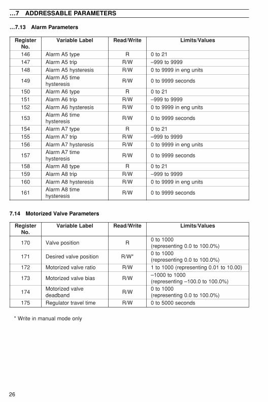
7.14 Motorized Valve Parameters

27
retsigeR.oN
lebaLelbairaV etirW/daeR seulaV/stimiL
081 noitacilppaetalpmeT R 12
3
4
5
6
789
01
112131
4151
6171
;tniopteslacolhtiwpoolelgniStesetomerhtiwpoolelgniS
;tniophtiwnoitatslaunaM/otuA
;noitceleslangiswolhtiwnoitatslaunaM/otuA
;noitceleslatigidhtiwpukcabgolanA
;noitceleslangiswolhtiwpukcabgolanA;noitceleslatigid
;redaollaunam/rotacidnielgniS;redaollaunam/rotacidnielbuoD
drawrofdeefhtiwpoolelgniS;tniopteslacoldna
drawrofdeefhtiwpoolelgniS;tnioptesetomerdna
;tniopteslacolhtiwedacsaC;tnioptesetomerhtiwedacsaC
drawrofdeefhtiwedacsaC;tniopteslacoldna
;rellortnocoitaRlanretxehtiwrellortnocoitaR
;oitar;noitatsoitaR
oitarlanretxehtiwnoitatsoitaR
…deunitnoC
7 ADDRESSABLE PARAMETERS…
7.15 Basic Configuration

28
retsigeR.oN
lebaLelbairaV etirW/daeR seulaV/stimiL
012 tluser1kcolbhtaM R 9999ot999–
112 tluser2kcolbhtaM R 9999ot999–
212 tluser3kcolbhtaM R 9999ot999–
312 tluser4kcolbhtaM R 9999ot999–
412 s'pd1kcolbhtaM R 3ot0
512 s'pd2kcolbhtaM R 3ot0
612 s'pd3kcolbhtaM R 3ot0
712 s'pd4kcolbhtaM R 3ot0
retsigeR.oN
lebaLelbairaV etirW/daeR seulaV/stimiL
181 epyttuptuO R 012345
6
7
8
901
1121
;enoN;)1oa=POC(tuptuogolanA;)1YLR=POC(tuptuoyaleR
;)1od=POC(tuptuolatigiD;kcabdeefhtiwevlavdezirotoM
tuohtiwevlavdezirotoM;kcabdeefhtiwlooc/taeH
;yaler=2PO,yaler=1PO,yaler=1POhtiwlooc/taeH
;tuptuolatigid=2POhtiwlooc/taeH
,tuptuolatigid=1PO;yaler=2PO
;desUtoNhtiwlooc/taeH
;yaler=2PO,golana=1PO;desUtoN
htiwlooc/taeH,golana=1PO
golana=2PO281 noitcalortnoC R 0
123
45
;esreveR=1PO;tceriD=1PO
;tceriD=2PO,esreveR=1PO,esreveR=1PO
esreveR=2PO;esreveR=2PO,tceriD=1PO
tceriD=2PO,tceriD=1PO
…7 ADDRESSABLE PARAMETERS
…7.15 Basic Configuration
7.16 Math Blocks

29
retsigeR.oN
lebaLelbairaV etirW/daeR seulaV/stimiL
003 nigeB1margorP W/R 99ot1;ffo=0
103 dnE1margorP W/R 99ot1
203 staepeR1margorP W/R ytinifnI=001;99ot0
303deetnarauG1margorP
siseretsyhpmarW/R 9999ot0
403deetnarauG1margorP
siseretsyhkaosW/R 9999ot0
503 ecruoS1margorP W/Rsecruoslatigidforebmunot0
1.7elbaTees–903ot603 desUtoN – –
513ot013 sretemaraP2margorP
W/RsretemaraP1margorPeeS
)503ot003sretsigeR(
523ot023 sretemaraP3margorP
533ot033 sretemaraP4margorP
543ot043 sretemaraP5margorP
553ot053 sretemaraP6margorP
563ot063 sretemaraP7margorP
573ot073 sretemaraP8margorP
583ot083 sretemaraP9margorP
593ot093 sretemaraP01margorP 1•
504ot004 sretemaraP11margorP 1•
514ot014 sretemaraP21margorP 1•
524ot024 sretemaraP31margorP 1•
534ot034 sretemaraP41margorP 1•
544ot044 sretemaraP51margorP 1•
554ot054 sretemaraP61margorP 1•
564ot064 sretemaraP71margorP 1•
574ot074 sretemaraP81margorP 1•
584ot084 sretemaraP91margorP 1•
594ot094 sretemaraP02margorP 1•
ylno063REDNAMMOC1•
7 ADDRESSABLE PARAMETERS…
7.17 Ramp/Soak Program Parameters (COMMANDER 355 and 360 Instruments Only)
Note. On the instrument display, programs 10 to 20 are represented by the letters A to L(excluding I).
30
retsigeR.oN
lebaLelbairaV etirW/daeR seulaV/stimiL
005 eulaVtratS1tnemgeS W/R.pdon,stinugnireenigneni9999ot0
0152sa01.52,0001saderetnesi0.001105 eulaVdnE1tnemgeS W/R stinugnireenigneni9999ot0
2051tnemgeS
etaRpmaR/emiTkaoSW/R
:26dna16slioCfosgnittesnosdnepeDro)sruoh0.861ot0.0=(0861ot0
ro)setunim9.999ot0.0=(9999ot0nim/rorh/*stinugnireenignE9999ot1
lortnocehtnahtecalplamicederomeno*.p.d3fomumixamaotpu,tnioptes
305deetnarauG1tnemgeSelbanesiseretsyhpmar
W/R;ylnotnioptesevobasiseretsyh=1;ffo=0
;ylnotniopteswolebsiseretsyh=2.tniopteswolebdnaevobasiseretsyh=3
405 etatStnevEemiT W/R
1=nO1tnevE2=nO2tnevE4=nO3tnevE8=nO4tnevE
tes,evitca4dna2stneveekamoT.g.E01=2+8otretsigersiht 01 A( 61 )
505 desUtoN –605 eulaVdnE2tnemgeS W/R
sretemaraP1tnemgeSeeS
7052tnemgeS
etaRpmaR/emiTkaoSW/R
805deetnarauG2tnemgeSelbanesiseretsyhpmar
W/R
905 etatStnevEemiT W/R015 desUtoN –
515ot115 sretemarap3tnemgeS
W/R
: :056ot646 sretemarap03tnemgeS556ot156 sretemarap13tnemgeS 1•
: : 1•599ot199 sretemaraP99tnemgeS 1•
699 eulavtsujdaemitkaoS W/Rni0.001ot0.0gnitneserper,0001ot0
detcelesstinuemit799 troteR W/R BepyT=2;AepyT=1;ffo=0
899–kaoSpmaR
margorptnerrucnuRW/RroR
smargorP02ot1 rororororo dloh/nurnehwylno'POTS'=noitca
999–kaoSpmaR
tnemgestnerrucnuRR 99ot1
0001 noitcAdloH/nuRtnerruC R
dloHrotarepO=0potS=1nuR=2dnE=3
dloHlaunaM=4dloHkcabdloH=5
ylno063REDNAMMOC1•
…7 ADDRESSABLE PARAMETERS
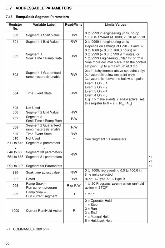
7.18 Ramp/Soak Segment Parameters

31
latigiDecruoS
.oNnoitpircseD
latigiDecruoS
.oNnoitpircseD
0 eslaFsyawla–langisffO 24 1mralaemitlaeR1 )taeh(1tuptuolortnoC 34 2mralaemitlaeR2 )looc(2tuptuolortnoC 44 1remityaleD3 yaleRnepOevlavdezirotoM 54 2remityaleD4 yaleResolCevlavdezirotoM 64 1langissubdoM5 evitca1mralA 74 2langissubdoM6 evitca2mralA 84 3langissubdoM7 evitca3mralA 94 4langissubdoM8 evitca4mralA 05 eurTsyawla–langisnO9 evitca5mralA 15 1etatstneveemiT01 evitca6mralA 25 2etatstneveemiT11 evitca7mralA 35 3etatstneveemiT21 evitca8mralA 45 4etatstneveemiT31 egdelwonkca1mralA 55 tnevemargorpfodnE41 egdelwonkca2mralA 65 1etatstnevemargorP51 egdelwonkca3mralA 75 2etatstnevemargorP61 egdelwonkca4mralA 85 3etatstnevemargorP71 egdelwonkca5mralA 95 4etatstnevemargorP81 egdelwonkca6mralA 06 5etatstnevemargorP91 egdelwonkca7mralA 16 6etatstnevemargorP02 egdelwonkca8mralA 26 7etatstnevemargorP12 1tupnilatigiD 36 8etatstnevemargorP22 2tupnilatigiD 46 9etatstnevemargorP32 3tupnilatigiD 56 )A(01etatstnevemargorP 1•42 4tupnilatigiD 66 )B(11etatstnevemargorP 1•52 edomlortnoclaunaM 76 )C(21etatstnevemargorP 1•62 edomlortnocotuA 86 )D(31etatstnevemargorP 1•72 lortnoclacoL/tniopteslacoL
detceles96 )E(41etatstnevemargorP 1•07 )F(51etatstnevemargorP 1•
82 etomeR/tnioptesetomeRdetceleslortnoc
17 )G(61etatstnevemargorP 1•27 )H(71etatstnevemargorP 1•
92 deliaf1tupnI 37 )J(81etatstnevemargorP 1•03 deliaf2tupnI 47 )K(91etatstnevemargorP 1•13 deliaf3tupnI 57 )L(02etatstnevemargorP 1•23 1p/ogolanakaerbpooL 67 1etatstnevetnemgeS33 desUtoN : :43 evitcagodhctaW 501 03etatstnevetnemgeS53 liafrewoP 601 13etatstnevetnemgeS 1•63 eurt1noitauqecigoL : : 1•73 eurt2noitauqecigoL 471 99etatstnevetnemgeS 1•83 eurt3noitauqecigoL 571 gninnuRmargorP93 eurt4noitauqecigoL 671 dloHmargorPkcabdloH04 eurt5noitauqecigoL 771 dloHmargorProtarepO14 eurt6noitauqecigoL 871 eurTsyawla–langisnO
ylno063REDNAMMOC1•
7 ADDRESSABLE PARAMETERS
Table 7.1 Digital Sources

32
NOTES

PRODUCTS & CUSTOMER SUPPORTProductsAutomation Systems
• for the following industries:– Chemical & Pharmaceutical– Food & Beverage– Manufacturing– Metals and Minerals– Oil, Gas & Petrochemical– Pulp and Paper
Drives and Motors• AC and DC Drives, AC and DC Machines,
AC motors to 1kV• Drive systems• Force Measurement• Servo Drives
Controllers & Recorders• Single and Multi-loop Controllers• Circular Chart , Strip Chart and Paperless
Recorders• Paperless Recorders• Process Indicators
Flexible Automation• Industrial Robots and Robot Systems
Flow Measurement• Electromagnetic Magnetic Flowmeters• Mass Flow Meters• Turbine Flowmeters• Wedge Flow Elements
Marine Systems & Turbochargers• Electrical Systems• Marine Equipment• Offshore Retrofit and Referbishment
Process Analytics• Process Gas Analysis• Systems Integration
Transmitters• Pressure• Temperature• Level• Interface Modules
Valves, Actuators and Positioners• Control Valves• Actuators• Positioners
Water, Gas & Industrial AnalyticsInstrumentation
• pH, conductivity, and dissolved oxygentransmitters and sensors
• ammonia, nitrate, phosphate, silica,sodium, chloride, fluoride, dissolvedoxygen and hydrazine analyzers.
• Zirconia oxygen analyzers, katharometers,hydrogen purity and purge-gas monitors,thermal conductivity.
Customer SupportABB Automation provides a comprehensive after salesservice via our Worldwide Service Organization.Contact one of the following offices for details on yournearest Service and Repair Centre.
United KingdomABB Automation LimitedTel: +44 (0)1480-475-321Fax: +44 (0)1480-217-948
United States of AmericaABB Automation Inc.Instrumentation DivisionTel: +1 215-674-6000Fax: +1 215-674-7183
Client Warranty
Prior to installation, the equipment referred to inthis manual must be stored in a clean, dryenvironment, in accordance with the Company'spublished specification. Periodic checks must bemade on the equipment's condition.
In the event of a failure under warranty, thefollowing documentation must be provided assubstantiation:
1. A listing evidencing process operation andalarm logs at time of failure.
2. Copies of operating and maintenancerecords relating to the alleged faulty unit.

ABB Automation LtdHoward Road, St. NeotsCambridgeshire, PE19 8EUUKTel: +44 (0)1480-475-321Fax: +44 (0)1480-217-948
ABB Automation Inc125 E. County Line RoadWarminster, PA 18974USATel: +1 215-674-6000Fax: +1 215-674-7183
ABB has Sales & Customer Support expertisein over 100 countries worldwide
www.abb.com
IM/C
350–
MO
DIs
sue
5
The Company’s policy is one of continuous productimprovement and the right is reserved to modify the informationcontained herein without notice.
© ABB 2001 Printed in UK (05.01)


![Soak It Up! [#052 Special]](https://img.pdfslide.us/doc/110x75/568c52a41a28ab4916b77dde/soak-it-up-052-special.jpg)