Embed Size (px)
Citation preview
Cat. No. H078-E1-03C
USER’S MANUAL
E5CKDigital Controller

E5CK
Digital Controller
User's Manual
Cat. No. H078-E1-03C
Terms and Conditions of Sale1. Offer; Acceptance. These terms and conditions (these "Terms") are deemed
part of all quotes, agreements, purchase orders, acknowledgments, price lists,catalogs, manuals, brochures and other documents, whether electronic or inwriting, relating to the sale of products or services (collectively, the "Products")by Omron Electronics LLC and its subsidiary companies (“Omron”). Omronobjects to any terms or conditions proposed in Buyer’s purchase order or otherdocuments which are inconsistent with, or in addition to, these Terms.
2. Prices; Payment Terms. All prices stated are current, subject to change with-out notice by Omron. Omron reserves the right to increase or decrease priceson any unshipped portions of outstanding orders. Payments for Products aredue net 30 days unless otherwise stated in the invoice.
3. Discounts. Cash discounts, if any, will apply only on the net amount of invoicessent to Buyer after deducting transportation charges, taxes and duties, and willbe allowed only if (i) the invoice is paid according to Omron’s payment termsand (ii) Buyer has no past due amounts.
4. Interest. Omron, at its option, may charge Buyer 1-1/2% interest per month orthe maximum legal rate, whichever is less, on any balance not paid within thestated terms.
5. Orders. Omron will accept no order less than $200 net billing. 6. Governmental Approvals. Buyer shall be responsible for, and shall bear all
costs involved in, obtaining any government approvals required for the impor-tation or sale of the Products.
7. Taxes. All taxes, duties and other governmental charges (other than generalreal property and income taxes), including any interest or penalties thereon,imposed directly or indirectly on Omron or required to be collected directly orindirectly by Omron for the manufacture, production, sale, delivery, importa-tion, consumption or use of the Products sold hereunder (including customsduties and sales, excise, use, turnover and license taxes) shall be charged toand remitted by Buyer to Omron.
8. Financial. If the financial position of Buyer at any time becomes unsatisfactoryto Omron, Omron reserves the right to stop shipments or require satisfactorysecurity or payment in advance. If Buyer fails to make payment or otherwisecomply with these Terms or any related agreement, Omron may (without liabil-ity and in addition to other remedies) cancel any unshipped portion of Prod-ucts sold hereunder and stop any Products in transit until Buyer pays allamounts, including amounts payable hereunder, whether or not then due,which are owing to it by Buyer. Buyer shall in any event remain liable for allunpaid accounts.
9. Cancellation; Etc. Orders are not subject to rescheduling or cancellationunless Buyer indemnifies Omron against all related costs or expenses.
10. Force Majeure. Omron shall not be liable for any delay or failure in deliveryresulting from causes beyond its control, including earthquakes, fires, floods,strikes or other labor disputes, shortage of labor or materials, accidents tomachinery, acts of sabotage, riots, delay in or lack of transportation or therequirements of any government authority.
11. Shipping; Delivery. Unless otherwise expressly agreed in writing by Omron:a. Shipments shall be by a carrier selected by Omron; Omron will not drop ship
except in “break down” situations.b. Such carrier shall act as the agent of Buyer and delivery to such carrier shall
constitute delivery to Buyer;c. All sales and shipments of Products shall be FOB shipping point (unless oth-
erwise stated in writing by Omron), at which point title and risk of loss shallpass from Omron to Buyer; provided that Omron shall retain a security inter-est in the Products until the full purchase price is paid;
d. Delivery and shipping dates are estimates only; ande. Omron will package Products as it deems proper for protection against nor-
mal handling and extra charges apply to special conditions.12. Claims. Any claim by Buyer against Omron for shortage or damage to the
Products occurring before delivery to the carrier must be presented in writingto Omron within 30 days of receipt of shipment and include the original trans-portation bill signed by the carrier noting that the carrier received the Productsfrom Omron in the condition claimed.
13. Warranties. (a) Exclusive Warranty. Omron’s exclusive warranty is that theProducts will be free from defects in materials and workmanship for a period oftwelve months from the date of sale by Omron (or such other period expressedin writing by Omron). Omron disclaims all other warranties, express or implied.(b) Limitations. OMRON MAKES NO WARRANTY OR REPRESENTATION,EXPRESS OR IMPLIED, ABOUT NON-INFRINGEMENT, MERCHANTABIL-
ITY OR FITNESS FOR A PARTICULAR PURPOSE OF THE PRODUCTS.BUYER ACKNOWLEDGES THAT IT ALONE HAS DETERMINED THAT THEPRODUCTS WILL SUITABLY MEET THE REQUIREMENTS OF THEIRINTENDED USE. Omron further disclaims all warranties and responsibility ofany type for claims or expenses based on infringement by the Products or oth-erwise of any intellectual property right. (c) Buyer Remedy. Omron’s sole obli-gation hereunder shall be, at Omron’s election, to (i) replace (in the formoriginally shipped with Buyer responsible for labor charges for removal orreplacement thereof) the non-complying Product, (ii) repair the non-complyingProduct, or (iii) repay or credit Buyer an amount equal to the purchase price ofthe non-complying Product; provided that in no event shall Omron be responsi-ble for warranty, repair, indemnity or any other claims or expenses regardingthe Products unless Omron’s analysis confirms that the Products were prop-erly handled, stored, installed and maintained and not subject to contamina-tion, abuse, misuse or inappropriate modification. Return of any Products byBuyer must be approved in writing by Omron before shipment. Omron Compa-nies shall not be liable for the suitability or unsuitability or the results from theuse of Products in combination with any electrical or electronic components,circuits, system assemblies or any other materials or substances or environ-ments. Any advice, recommendations or information given orally or in writing,are not to be construed as an amendment or addition to the above warranty.See http://oeweb.omron.com or contact your Omron representative for pub-lished information.
14. Limitation on Liability; Etc. OMRON COMPANIES SHALL NOT BE LIABLEFOR SPECIAL, INDIRECT, INCIDENTAL, OR CONSEQUENTIAL DAMAGES,LOSS OF PROFITS OR PRODUCTION OR COMMERCIAL LOSS IN ANYWAY CONNECTED WITH THE PRODUCTS, WHETHER SUCH CLAIM ISBASED IN CONTRACT, WARRANTY, NEGLIGENCE OR STRICT LIABILITY.Further, in no event shall liability of Omron Companies exceed the individualprice of the Product on which liability is asserted.
15. Indemnities. Buyer shall indemnify and hold harmless Omron Companies andtheir employees from and against all liabilities, losses, claims, costs andexpenses (including attorney's fees and expenses) related to any claim, inves-tigation, litigation or proceeding (whether or not Omron is a party) which arisesor is alleged to arise from Buyer's acts or omissions under these Terms or inany way with respect to the Products. Without limiting the foregoing, Buyer (atits own expense) shall indemnify and hold harmless Omron and defend or set-tle any action brought against such Companies to the extent based on a claimthat any Product made to Buyer specifications infringed intellectual propertyrights of another party.
16. Property; Confidentiality. Any intellectual property in the Products is the exclu-sive property of Omron Companies and Buyer shall not attempt to duplicate itin any way without the written permission of Omron. Notwithstanding anycharges to Buyer for engineering or tooling, all engineering and tooling shallremain the exclusive property of Omron. All information and materials suppliedby Omron to Buyer relating to the Products are confidential and proprietary,and Buyer shall limit distribution thereof to its trusted employees and strictlyprevent disclosure to any third party.
17. Export Controls. Buyer shall comply with all applicable laws, regulations andlicenses regarding (i) export of products or information; (iii) sale of products to“forbidden” or other proscribed persons; and (ii) disclosure to non-citizens ofregulated technology or information.
18. Miscellaneous. (a) Waiver. No failure or delay by Omron in exercising any rightand no course of dealing between Buyer and Omron shall operate as a waiverof rights by Omron. (b) Assignment. Buyer may not assign its rights hereunderwithout Omron's written consent. (c) Law. These Terms are governed by thelaw of the jurisdiction of the home office of the Omron company from whichBuyer is purchasing the Products (without regard to conflict of law princi-ples). (d) Amendment. These Terms constitute the entire agreement betweenBuyer and Omron relating to the Products, and no provision may be changedor waived unless in writing signed by the parties. (e) Severability. If any provi-sion hereof is rendered ineffective or invalid, such provision shall not invalidateany other provision. (f) Setoff. Buyer shall have no right to set off any amountsagainst the amount owing in respect of this invoice. (g) Definitions. As usedherein, “including” means “including without limitation”; and “Omron Compa-nies” (or similar words) mean Omron Corporation and any direct or indirectsubsidiary or affiliate thereof.
Certain Precautions on Specifications and Use1. Suitability of Use. Omron Companies shall not be responsible for conformity
with any standards, codes or regulations which apply to the combination of theProduct in the Buyer’s application or use of the Product. At Buyer’s request,Omron will provide applicable third party certification documents identifyingratings and limitations of use which apply to the Product. This information byitself is not sufficient for a complete determination of the suitability of the Prod-uct in combination with the end product, machine, system, or other applicationor use. Buyer shall be solely responsible for determining appropriateness ofthe particular Product with respect to Buyer’s application, product or system.Buyer shall take application responsibility in all cases but the following is anon-exhaustive list of applications for which particular attention must be given:(i) Outdoor use, uses involving potential chemical contamination or electricalinterference, or conditions or uses not described in this document.(ii) Use in consumer products or any use in significant quantities. (iii) Energy control systems, combustion systems, railroad systems, aviationsystems, medical equipment, amusement machines, vehicles, safety equip-ment, and installations subject to separate industry or government regulations. (iv) Systems, machines and equipment that could present a risk to life or prop-erty. Please know and observe all prohibitions of use applicable to this Prod-uct. NEVER USE THE PRODUCT FOR AN APPLICATION INVOLVING SERIOUSRISK TO LIFE OR PROPERTY OR IN LARGE QUANTITIES WITHOUTENSURING THAT THE SYSTEM AS A WHOLE HAS BEEN DESIGNED TO
ADDRESS THE RISKS, AND THAT THE OMRON’S PRODUCT IS PROP-ERLY RATED AND INSTALLED FOR THE INTENDED USE WITHIN THEOVERALL EQUIPMENT OR SYSTEM.
2. Programmable Products. Omron Companies shall not be responsible for theuser’s programming of a programmable Product, or any consequence thereof.
3. Performance Data. Data presented in Omron Company websites, catalogsand other materials is provided as a guide for the user in determining suitabil-ity and does not constitute a warranty. It may represent the result of Omron’stest conditions, and the user must correlate it to actual application require-ments. Actual performance is subject to the Omron’s Warranty and Limitationsof Liability.
4. Change in Specifications. Product specifications and accessories may bechanged at any time based on improvements and other reasons. It is our prac-tice to change part numbers when published ratings or features are changed,or when significant construction changes are made. However, some specifica-tions of the Product may be changed without any notice. When in doubt, spe-cial part numbers may be assigned to fix or establish key specifications foryour application. Please consult with your Omron’s representative at any timeto confirm actual specifications of purchased Product.
5. Errors and Omissions. Information presented by Omron Companies has beenchecked and is believed to be accurate; however, no responsibility is assumedfor clerical, typographical or proofreading errors or omissions.
I
�������������� ������������������� ����������������������������������
���������������������������������������������
• ������������������ �������� ������������������� �� ���� ����� �!
• �������� ������������������������ ���������� � ������������!
• "��������� ����� ����#�$�������!
• %���������������� �&��'()� ' �(�����)����!
• "�������������������������
• ����&������� �������������� �
• *������������������������������������� +�%),���-�.��������*$//!
�����"���0��%�����������&���������������������� ���������#�����������������#
�������
(������������������������������������������������������������������
����������������
About this manual
� OMRON, 1995(1) All rights reserved. No part of this publication may be reproduced, stored in a retrieval system, or transmitted,
in any form, or by any means, mechanical, electronic, photocopying, recording, recording, or otherwise, withoutthe prior written permission of OMRON.
(2) No patent liability is assumed with respect to the use of the information contained herein.(3) Moreover, because OMRON is constantly striving to improve its high-quality products, the information in this
manual is subject to change without notice. Every precaution has been taken in the preparation of this manual.Nevertheless, OMRON assumes no responsibility for errors or omissions. Neither is any liability assumed fordamages resulting from the use of the information contained in this publication.
Preface
II
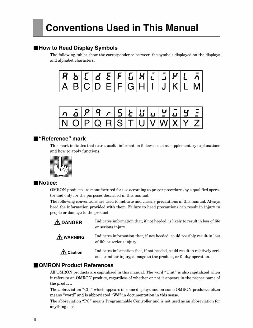
�How to Read Display Symbols��������������&����������������� �������&��������������&������ ��������������� ����
������ ��&��������������
A B C D E F G H I J K L M
N O P Q R S T U V W X Y Z
�“Reference” mark��������������������������1����������������������������������� �����������1 ��������
���������� �����������
�Notice:2%32+� �������������������������������������� � ��� ��������&����-�������� ���#
������������������ � ����������&�����������������
��������������.��������������������������������������� ������������������������)�����
������������������� �.����������������4������������� ������������������������5����
� ������������������ �����
*����������������������������������������������������������������������
����������5���
*������������������������������������������� ���&���������������
�����������������5���
*����������������������������������������������������������.��������#
�����������5����������������� �������������� �������
�OMRON Product References)���2%32+� ������������ �����6��������������������������7"���8���������� �����6�������
���������������2%32+� ������������������������������������ ������������ � ���������
���� �����
�����&&��.������7���8�������� ��������������� ���������������2%32+� �����������
������7���8���������&&��.������79�8�����������������������������
�����&&��.������7$�8�������$�������&���������������������������������&&��.��������
��������������
Conventions Used in This Manual
DANGER
WARNING
Caution
III
�How this Manual is Organized
Purpose Title Description
Learning about the gen-eral features of the E5CK
��� ����:��*�������� ����� ��� ���� ������&��� ���� ���#����� �� ���� ������ ������ � ������������ �������������
Setting up the E5CK ��� ����;��$�� ������� �������� ����������&������� ���#����� ����� �� ���� ������ � ����� ������������� ������� ���������� ��������!� &����� �� ���������������
Basic E5CK operations ��� ����<��(�����2 ��������� �������$���������
������ ��� ����� ������&�� ���������������� ������������������.����������� �������������������� ������������������5�����#�����������������
Applied E5CK operations ��� ����,��) �����2 ��������� �������$���������
������ ��� ����� ������&�� ����� ������������������������������� �� ��� ���� �������������������������������������
Communications with ahost computer
��� ����/��"������������#���������4�����
����� ��� ���� ������� ������&������ ��������������������������.��� �������1�� ����
Calibration ��� ����,��) �����2 ������=�,�������&�����
����� ��� ���� ������&��� �������������������&��������������
Troubleshooting ��� ����>����&�������� �������� ����������&������������������ �&���������
IV
� *�������.�������������������������������.����������� �����������������������
������������
� ?�����.�������� �����&�������������������� ����������������� ������������
��������������������������� ��!
� "�����.������ )�:@@#;,@A ��)�=?�;,A ����@���/@�B6!��)�� ����2+������ ��#
����&���.��������.�������&����������������������������
� 9������������� ����� �������������������������� ������������� ������������
�������������������������������.�������
C• )�������-����� ����&����������������.�����=������� �������������������� �=�#
��������
C• ).��� ��������������������������������.���������������� ������������������
��������������
C• "������� �������� � ������������������������������������������ ����������������������
������������������������.�������
� )������������ ������� ���&���&��������������������������.��������������������� �#
��������������-����� ����#���-������������������#���-���������������������������
����!�����������������.�������������������������
� *������������������� ���#����������� ��� ��������.��������������������������������������
� ����������������������������.�������� ����������������������������������������
*�� ���������������������������������������������������������.��������������
�� ��������������������������������.����������������
� 9������������������ ��������&������������������������������0��.����������������
�� �������������������������������������� ���&������������������
� ?����������������������� �����������������������������������������.������ �� �#
������������6�������������������!��������.�&�������� ����������-������������#
� ����������)�����.��� �����������������������������&���&5��������������������
��������� �����������������!������������ ���������������
� )�&�������� �����������&���� ��&�������#:@�����������)�&�����������������&�
�� ��&�������<�D3B���E�D3B� �������������������������!��*�����������������
�������������������������&�����������&�������� �����������&���� ������������
���������������� ��������������������������*�������������������&5������������
��������������������������������������������������������������
� ��������������������������&�������� �������&�������#;������/�����������&����
������������&��&�������<�D3B���E�D3B� �������������������������!�
� +�.��� ��������.��&5����������� ��� ����������������������������������������
����������������������������������������
� ).������������������������ �����������������������.���������������������������������
��������.������������������������&��������������.������������������ �����������
�������������
Pay Attention to the Following when Installingthis Controller
Preface I. . . . . . . . . . . . . . . . . . . . . . . . . . . . . . . . . . . . . . Conventions Used in This Manual II. . . . . . . . . . . . . . . Pay Attention to the Following when Installingthis Controller IV. . . . . . . . . . . . . . . . . . . . . . . . . . . . . . . . .
CHAPTER 1 INTRODUCTION 1–1. . . . . . . . . . . . . . . . . . . . . . . . . . This chapter introduces the E5CK. First-time users should read this chapter with-out fail.For details on how to use the controller and parameter settings, see Chapters 2onwards.
1.1 Names of parts 1–2. . . . . . . . . . . . . . . . . . . . . . . . . . . . . . . . . . . . . . . . . .
1.2 Input and Output 1–4. . . . . . . . . . . . . . . . . . . . . . . . . . . . . . . . . . . . . . . . . 1.3 Parameters and Menus 1–6. . . . . . . . . . . . . . . . . . . . . . . . . . . . . . . . . . .
1.4 About the Communications Function 1–9. . . . . . . . . . . . . . . . . . . . . . . 1.5 About Calibration 1–10. . . . . . . . . . . . . . . . . . . . . . . . . . . . . . . . . . . . . . . .
CHAPTER 2 PREPARATIONS 2–1. . . . . . . . . . . . . . . . . . . . . . . . . . This chapter describes the operations you should carry out before turning theE5CK ON.
2.1 Setting up 2–2. . . . . . . . . . . . . . . . . . . . . . . . . . . . . . . . . . . . . . . . . . . . . . . 2.2 Installation 2–4. . . . . . . . . . . . . . . . . . . . . . . . . . . . . . . . . . . . . . . . . . . . . . 2.3 Wiring Terminals 2–6. . . . . . . . . . . . . . . . . . . . . . . . . . . . . . . . . . . . . . . . .
CHAPTER 3 BASIC OPERATION 3–1. . . . . . . . . . . . . . . . . . . . . . . . This chapter describes an actual example for understanding the basic operationof the E5CK.
3.1 Control Example 3–2. . . . . . . . . . . . . . . . . . . . . . . . . . . . . . . . . . . . . . . . . 3.2 Setting Input Specifications 3–3. . . . . . . . . . . . . . . . . . . . . . . . . . . . . . .
3.3 Setting Output Specifications 3–5. . . . . . . . . . . . . . . . . . . . . . . . . . . . . . 3.4 Setting Alarm Type 3–7. . . . . . . . . . . . . . . . . . . . . . . . . . . . . . . . . . . . . . . 3.5 Protect Mode 3–10. . . . . . . . . . . . . . . . . . . . . . . . . . . . . . . . . . . . . . . . . . . .
3.6 Starting and Stopping Operation 3–11. . . . . . . . . . . . . . . . . . . . . . . . . . . 3.7 Adjusting Control Operation 3–12. . . . . . . . . . . . . . . . . . . . . . . . . . . . . . .
CHAPTER 4 APPLIED OPERATION 4–1. . . . . . . . . . . . . . . . . . . . . This chapter describes each of the parameters required for making full use of thefeatures of the E5CK. Read this chapter while referring to the parameter descrip-tions in chapter 5.
4.1 Selecting the Control Method 4–2. . . . . . . . . . . . . . . . . . . . . . . . . . . . . .
4.2 Operating Condition Restrictions 4–4. . . . . . . . . . . . . . . . . . . . . . . . . . . 4.3 How to Use Option Functions 4–7. . . . . . . . . . . . . . . . . . . . . . . . . . . . . 4.4 LBA 4–9. . . . . . . . . . . . . . . . . . . . . . . . . . . . . . . . . . . . . . . . . . . . . . . . . . . .
4.5 Calibration 4–11. . . . . . . . . . . . . . . . . . . . . . . . . . . . . . . . . . . . . . . . . . . . . .
Table of Contents
CHAPTER 5 PARAMETERS 5–1. . . . . . . . . . . . . . . . . . . . . . . . . . . . This chapter describes the parameters of the E5CK. Use this chapter as a refer-ence guide.
Conventions Used in this Chapter 5–2. . . . . . . . . . . . . . . . . . . . . . . . . . . . . .
Protect Mode 5–3. . . . . . . . . . . . . . . . . . . . . . . . . . . . . . . . . . . . . . . . . . . . . . . .
Manual Mode 5–5. . . . . . . . . . . . . . . . . . . . . . . . . . . . . . . . . . . . . . . . . . . . . . . .
Level 0 Mode 5–6. . . . . . . . . . . . . . . . . . . . . . . . . . . . . . . . . . . . . . . . . . . . . . . .
Level 1 Mode 5–9. . . . . . . . . . . . . . . . . . . . . . . . . . . . . . . . . . . . . . . . . . . . . . . .
Level 2 Mode 5–15. . . . . . . . . . . . . . . . . . . . . . . . . . . . . . . . . . . . . . . . . . . . . . . .
Setup Mode 5–21. . . . . . . . . . . . . . . . . . . . . . . . . . . . . . . . . . . . . . . . . . . . . . . . .
Expansion Mode 5–27. . . . . . . . . . . . . . . . . . . . . . . . . . . . . . . . . . . . . . . . . . . . .
Option Mode 5–32. . . . . . . . . . . . . . . . . . . . . . . . . . . . . . . . . . . . . . . . . . . . . . . . .
Calibration Mode 5–36. . . . . . . . . . . . . . . . . . . . . . . . . . . . . . . . . . . . . . . . . . . . .
CHAPTER 6 USING THE COMMUNICATIONS FUNCTION 6–1.This chapter mainly describes communications with a host computer and com-munications commands.
6.1 Outline of the Communications Function 6–2. . . . . . . . . . . . . . . . . . . .
6.2 Preparing for Communications 6–3. . . . . . . . . . . . . . . . . . . . . . . . . . . .
6.3 Command Configuration 6–5. . . . . . . . . . . . . . . . . . . . . . . . . . . . . . . . . .
6.4 Commands and Responses 6–6. . . . . . . . . . . . . . . . . . . . . . . . . . . . . . .
6.5 How to Read Communications Error Information 6–10. . . . . . . . . . . . .
6.6 Program Example 6–12. . . . . . . . . . . . . . . . . . . . . . . . . . . . . . . . . . . . . . .
CHAPTER 7 TROUBLESHOOTING 7–1. . . . . . . . . . . . . . . . . . . . . . This chapter describes how to find out and remedy the cause if the E5CK doesnot function properly.
7.1 Initial Checks 7–2. . . . . . . . . . . . . . . . . . . . . . . . . . . . . . . . . . . . . . . . . . . .
7.2 How to Use the Error Display 7–3. . . . . . . . . . . . . . . . . . . . . . . . . . . . . .
7.3 How to Use Error Output 7–5. . . . . . . . . . . . . . . . . . . . . . . . . . . . . . . . . .
7.4 Checking Operation Restrictions 7–6. . . . . . . . . . . . . . . . . . . . . . . . . . .
APPENDIXSPECIFICATIONS A–2. . . . . . . . . . . . . . . . . . . . . . . . CONTROL BLOCK DIAGRAM A–5. . . . . . . . . . . . . . SETTING LIST A–6. . . . . . . . . . . . . . . . . . . . . . . . . . . PARAMETER OPERATIONS LIST A–8. . . . . . . . . . FUZZY SELF–TUNING A–10. . . . . . . . . . . . . . . . . . . . MODEL LIST A–13. . . . . . . . . . . . . . . . . . . . . . . . . . . . . X FORMAT A–14. . . . . . . . . . . . . . . . . . . . . . . . . . . . . . . ASCII CODE LIST A–17. . . . . . . . . . . . . . . . . . . . . . . .
INDEXREVISION HISTORY
CHAPTER 1 INTRODUCTION
1–1
CHAPTER 1INTRODUCTION
�������� �����������������������4����#������������������������
��� ���������������
4������������������������������������� ����������������������
��� �����;��������
CHAPTER1
:�: +������� ���� :F;������������������������������������������������
%���� ���� :F;��������������������������������������������������������
4���� ���� :F;������������������������������������������������������
)&��������� ���� :F<������������������������������������������
B����������� :F<����������������������������������������������
:�; *� ������2� � :F,��������������������������������������������
*� � :F,������������������������������������������������������������������
2� � :F�����������������������������������������������������������������
:�< $��������������%��� :F/����������������������������������
$����������� �� :F/����������������������������������������������
�������������� :F>������������������������������������������������
���������� ��������� :FE��������������������������������������
4�1������������ :FE��������������������������������������������������
:�, )&������������������4����� :FG��������
:�� )&������&����� :F:@��������������������������������������������
CHAPTER 1 INTRODUCTION
1–2
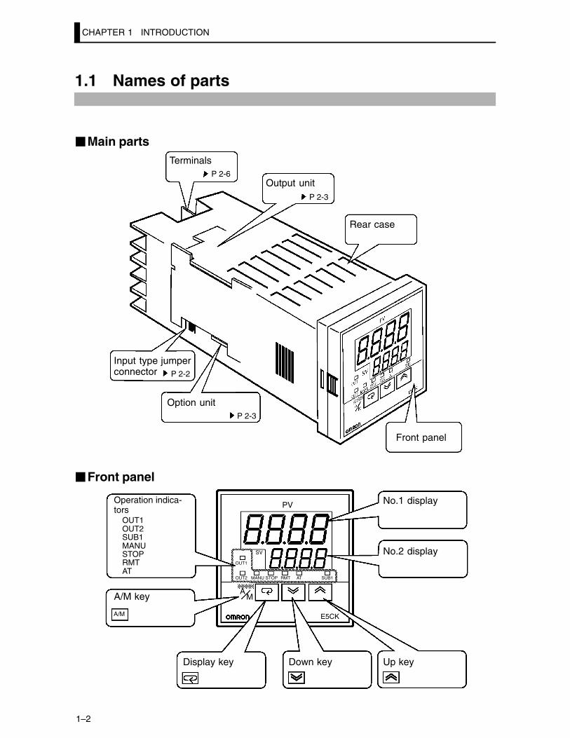
1.1 Names of parts
�Main parts
P 2-6
P 2-3
P 2-2
P 2-3
Input type jumperconnector
Option unit
Terminals
Rear case
Output unit
Front panel
�Front panel
OUT1OUT2SUB1MANUSTOPRMTAT
Operation indica-tors
A/M key
Display key Down key Up key
No.2 display
No.1 display
E5CK
PV
SV
OUT1
OUT2 MANU STOP RMT AT SUB1
AM
A/M
1.1 Names of parts
1–3
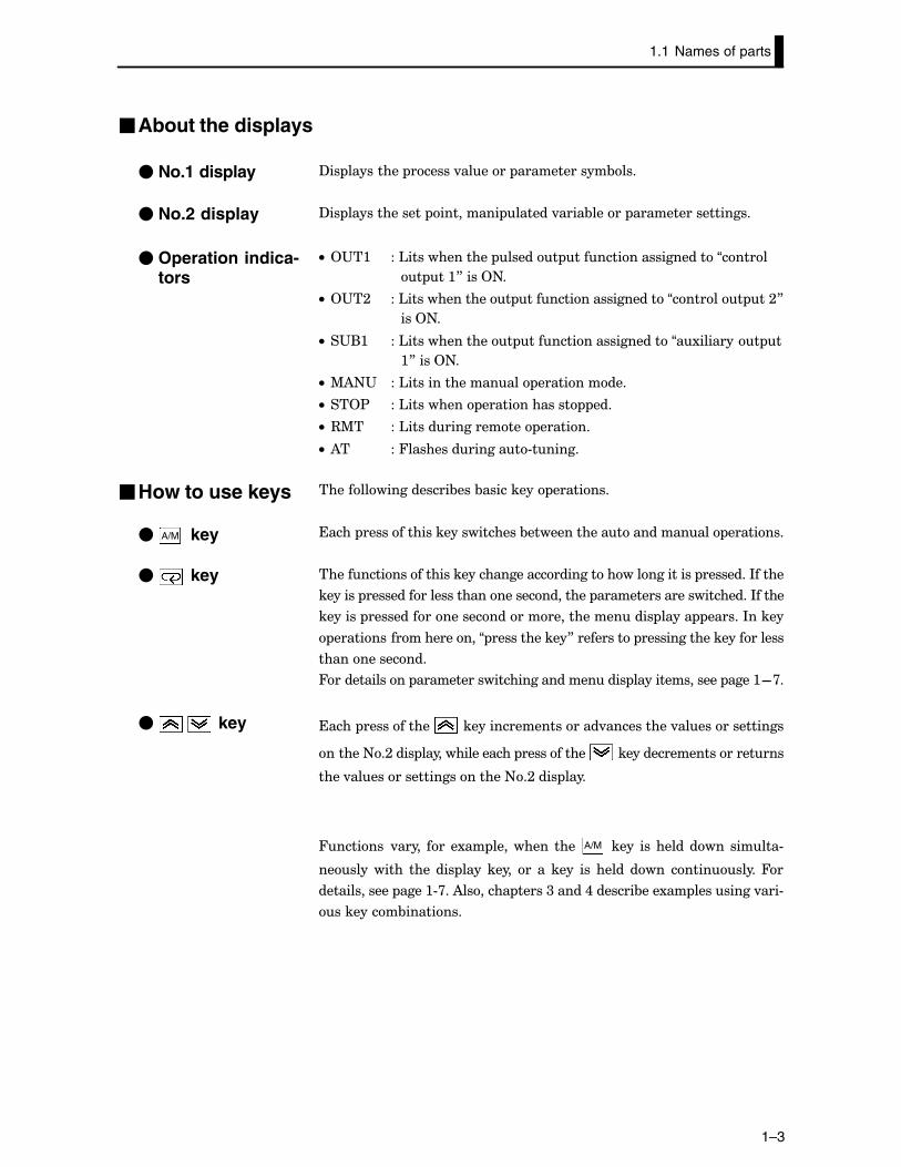
�About the displays
?�� ��������� ������.������ ������������&���
?�� ������������� ��������� ������.����&����� ������������������
C• 2"�: ��'������������� ������ ��������������������“������
� ��:8����2+�
C• 2"�; ��'�������������� ��������������������“������� ��;8
���2+�
C• �"(: ��'�������������� ��������������������“�1�������� �
:8����2+�
C• %)+" ��'����������������� �����������
C• ��2$ ��'��������� ������������� ���
C• 3%� ��'���������������� �������
C• )� ��4���������������#������
������������������&���&��������� ��������
����� �������������������������&������������������������ ��������
������������������������������������������������������ ��������*�����
������� ���������������������������������� ������������������������*�����
������� ������������������������������������� ����� ������*�����
��������������������“ ������������8���������� �����������������������
��������������
4������������ ������������������������������ ��������������� ����:F>�
����� ����������� ��������������������.����������.���������������
������+�;���� ���������������� ����������� ������������������������
����.����������������������+�;���� ����
4������� .����� ��� �1�� ��������� ���� A/M � ���� ��� ����� ���� ������#
����������� ���� ��� ���� ����� �� �� ���� ��� ����� ���� ����������4�
������������� ����:#>��)������� �����<�����,�������&���1�� ���������.���#
��������&��������
� No.1 display
� No.2 display
� Operation indica-tors
�How to use keys
� keyA/M
� key
� key
CHAPTER 1 INTRODUCTION
1–4
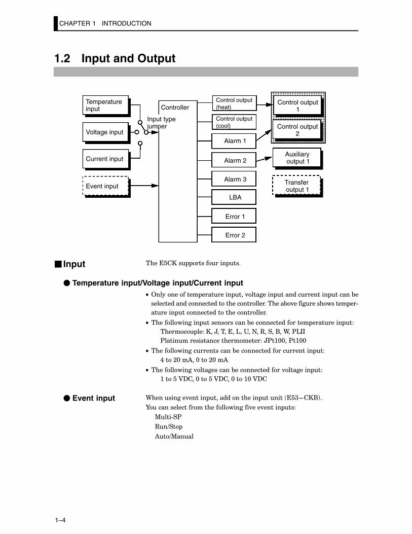
1.2 Input and Output
Alarm 2
Temperatureinput
Voltage input
Current input
Event input
ControllerControl output(heat)
Control output(cool)
Alarm 1
Alarm 3
LBA
Error 1
Error 2
Control output1
Control output2
Auxiliaryoutput 1
Transfer output 1
Input typejumper
���������� ��������� ���
� Temperature input/Voltage input/Current inputC• 2������������ ��������� ���.�������� ��������������� ������&�
�������������������������������������������&.���������������� ��#
������� ��������������������������
C• �������������� �������������&����������������� ��������� ��
������ ��� ���H��������'��"��+��3�����(��9��$'**
$������������������������������H$�:@@��$�:@@
C• ������������������������&����������������������� ��
,���;@��)��@���;@��)
C• ������������.�����������&��������������.�������� ��
:�����A?���@�����A?���@���:@�A?�
9����������.������ ��������������� ������ ��<F��(!�
I������������������������������.���.������ ���
%���#�$
3�=��
)�=%����
� Input
� Event input
1.2 Input and Output
1–5
�Output���������� �������������������� ���
������� ��:
������� ��;
)1�������� ��:
���������� �
9���������������� ���:�����;����������� ������ ������ �������!�
������� ������������.����&�������������� ��������������������
9������������������� ���������������������������� ��<F��4!�
Note: ����� �������������������������� �����������.�����������#
����������������������2+�
���������� ����������������������� ����������
������� �� ����!
������� �� ��!
)������:���<
'()
�����:� �� ������!
�����;� )=?���.����������!
)������������� ������������������� ���:�����;������1��������#
��:�
2����������� �� ����!��������� �� ��!���������:���<������'()
����&�������������������� ���:�����;��)���������������:���<��'()�
����������:�����;�����&��������������1�������� ��:�
*�������1�� ��������� ��.��� �����7������� �� ����!8������������
��7������� ��:8��7������:8���������������7������� ��;8�����
7������;8���������������7�1�������� ��:8��)����������������������#
������������������������������� ����������������������� ��:�
����������� ����������������������� ��;������1�������� ��:�
*������������������������������������7������� �� ��!8���������
��7������� ��:8���7������� ��;8�
���������� ������������������.������������ ���
���� ���
���� �����������$����
$������.���
B���������������� ������.����&��
��������������� ������.����&��
������ ���������� ��� ����&��� ��������&�������������������������
���������.��������������������������������.�������������������.����
����������������&������������
� Output assign-ments
� Transfer output
CHAPTER 1 INTRODUCTION
1–6
1.3 Parameters and Menus
����� ��������������������&����&�����������������������������
$���������
%��������
'�.���@����
'�.���:����
'�.���;����
��� ����
�1 ���������
2 �������
����&���������
��������������� ����������������������.�������� �1����������� �����
�����������������!�����&����������������������&����������������
������� ����
����������������������������������������� A/M ����������� ���������#
���������� ��.���������������������������� �����������������������
&������������������������ �������
*�� ����� ����� ���� ��������� ���� &�� ��������� ������ �������� ���
���� ������.����&�������&������ ������������������������������
���������������������������������������� ��������*�������������
������������������� ���������� �������������� ����������� �������
I��������������� ���������!����� ������.�������� ��$��������� #
������.����&���
��������������������������5�������������*�������������������1����
)�� ��#�����!����������������.���������������� ���������$*?� ����#
������
�������������1����������������5�������������*���������������������
���� ������������������������������ ������.����&����������� �����������
&��������������������������������������������� �&����������� '()!�
����������������������������������������.�������� ���
�������������������������������&������ �������������*�����������������
���� �������������������&����������������&����� �����������������
�� ���� ������������� ������������������������=��.����� �������
����������������������������1 ���������������*���������������������
��� ����#�����!���$�������������������������������.������$*?���2+=244
�������� ����������������������&����-������������������������������6�#
������ ��������������������������������������������������� ����
�Parameter types
� Protect mode
� Manual mode
� Level 0 mode
� Level 1 mode
� Level 2 mode
� Setup mode
� Expansion mode
1.3 Parameters and Menus
1–7
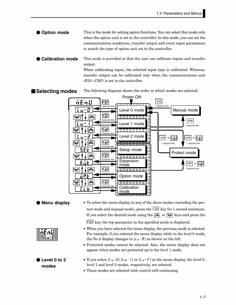
��������������������������� �������������I������������������������
��������� ��������������������������������*�������������������������
�������������������������������� �������.������ �� ���������
�������������� ���� ����������������������������
������������ �.����������������������������&������� ���������������
� ��
9���� ����&������� �� ������������������ ���� ���������&�������9�������
��������� � �� ����&�� ����&������ ��������� ���� ���������������
��<F��4!������������������������
�������������������������������������������������������������
A/M
A/M
A/M
A/M
A/M + +
+
1 second min.
Level 0 mode
Level 1 mode
Level 2 mode
Setup mode
Expansionmode
Option mode
Calibrationmode
1 second min.
Manual mode
1 second min.
1 second min. 1 second min.
Protect mode
1 second min.
1 second min.
Power ON
1 second min.
1 second min.
1 second min.
1 second min.
1 second min.
C• �������������������� ������������������&.������� �1����������� �#
����������������������!�� ��������� ��������:��������������
*������������������������������������ ��� ���������� ��������
����������� � ����������������� ������������������ ������
C• 9��������.���������������������� ��������� ��.�������������������
4���1�� ����������������������������� �������������������.���@�����
����+�;���� ��������������J K��������������������
C• $�������������������&������������)��������������� ����������
� ������������������ �������� ���������.���:�����
C• *�����������J K�J K���J K��������������� �����������.���@�
��.���:�������.���;���������� ����.������������������
C• ��������������������������������������������������
� Option mode
� Calibration mode
�Selecting modes
� Menu display
� Level 0 to 2modes
CHAPTER 1 INTRODUCTION
1–8
C• *�����������JCC K�JCC K�JCC K���JCC K��������������� ��������
��� �� �1 ������� ���� ���� ����&������ ������ ��� ����.����� ���
���������
C• 9����������������������������������������������������������� ��
�����1�������� ������������244��9��������������������������
���������������������������������������
C• ������������������������� ����������������������������.���@����
�������� ����������� ��������� A/M ��������� ��������:�����������#
���������������
C• ������������������������������������ ��������� A/M ��������:������
����������������.���@���;����������������������.���@������������
����������� ��������� A/M ��������:��������������
C• 9������������������������������ ����������� �����������������
���������
C• *���� ��������� ����������������������� ����������������� ����������
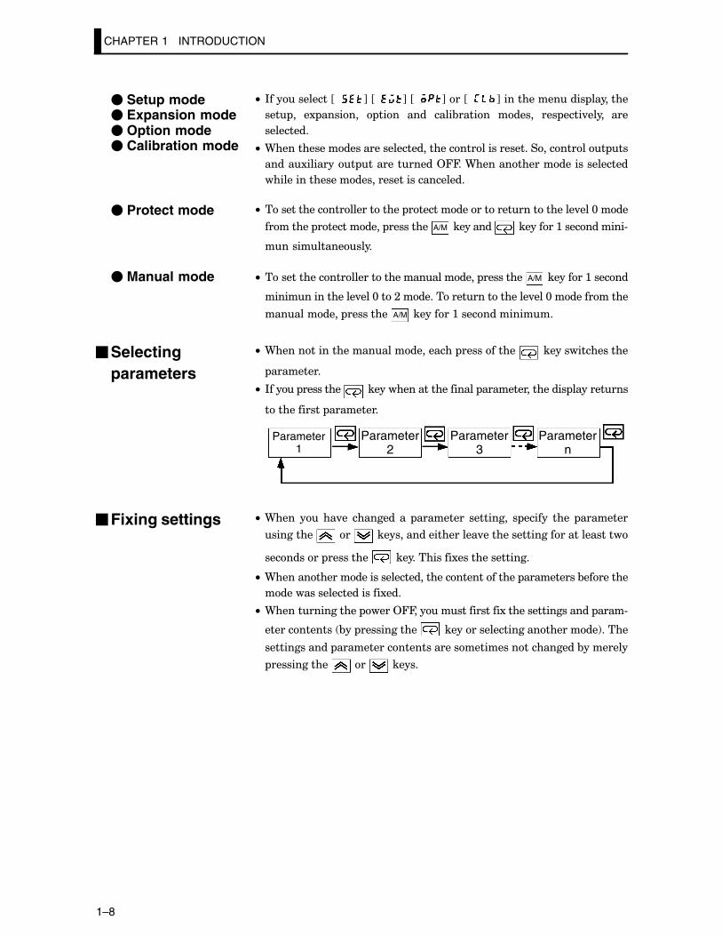
������������ ���������
Parameter1
Parameter2
Parameter3
Parametern
C• 9���� �� ��.�� �������� �� ��������� ��������� � ������ ���� ��������
��������� ��� ���������������������.����������������������������
��������� ��������� �������������1���������������
C• 9��������������������������������������������� ����������&��������
����������������������1���
C• 9��������������� ����244����������������1������������������ ����#
������������� &�� ������������ ���������������������������!�����
������������� �����������������������������������������&��������
������������ ��� ������
� Setup mode� Expansion mode� Option mode� Calibration mode
� Protect mode
� Manual mode
�Selectingparameters
�Fixing settings
1.4 About the Communications Function
1–9
1.4 About the Communications Function
�������������&�� �.�����������������������������������������
��������������������������� ���������������������� �����*�����
������������������������-��������������������������������
4����������������������������������������������� ����/�
9��������������������������������������3�F;<;����������������
���������������������� ��<F��@:!�
9��������������������������������������3�F,E����������������
���������������������� ��<F��@<!�
� RS-232C
� RS-485
CHAPTER 1 INTRODUCTION
1–10
1.5 About Calibration
�������������������������&������&�������� �����������������������
��������������������&���������������������������������������
B��.�����������������������������&������&������&�����������������
���������� �.������������������&�������� ��������� ����������� �
.�������������!��������������� ��
)�����������������&�������������� �������������������.�����������������
���������������������&�����������&���������������&�������� ��������
�����������������&����������������������&������&����������
������ ���� ������������������ �����������������������&������&����������
�������� �.�����������������������������&������ ����������
C• ������ ��
C• $����������������������������
C• ��������� �
C• A�������� �
��� �������������� �.�������������� �������.�������� ��
��������� � �� ���� &�� ����&������ ����� ���� ������������ ���
��<F��4!������������
9���� ����&������� ����� ������ ���� ����&������ ����� ��� ��� ������� �����#
���������������������&��������������������������&�����������������������
��������.��&��������������&������������������������&����� ������������#
���������������&�������������������������
9�����������������������������������������������������������&�����
����&��������������������������������
�� ����&����� ������ ������� ���� ���� ���� �� ���� �� ������ ��������
��.����������-� ������4��������������������������������������.����
�����-� ��������������������� ����.���������
4���������������,�������&������ ����,F::!�
� Calibratinginputs
� Calibrating trans-fer output
� Registering cal-ibration data
CHAPTER 2 PREPARATIONS
2–1
CHAPTER 2PREPARATIONS
�������� ����������&������� �����������������������&��������#
�������������2+�
CHAPTER2
;�: �������� ;F;����������������������������������������������������������
?���#� ;F;������������������������������������������������������������
�������������� ���� � ;F;������������������������������������
�������� ������ ����� ;F<����������������������������
�������� ����� ������� ;F<������������������������������
;�; *���������� ;F,��������������������������������������������������������
?�������� ;F,��������������������������������������������������������
$�������� ;F,������������������������������������������������������
%����� ;F�����������������������������������������������������������
;�< 9��������������� ;F/��������������������������������������������
�������������������� ;F/����������������������������������
$�������������������� ;F/������������������������������
9����� ;F/����������������������������������������������������������������
CHAPTER 2 PREPARATIONS
2–2
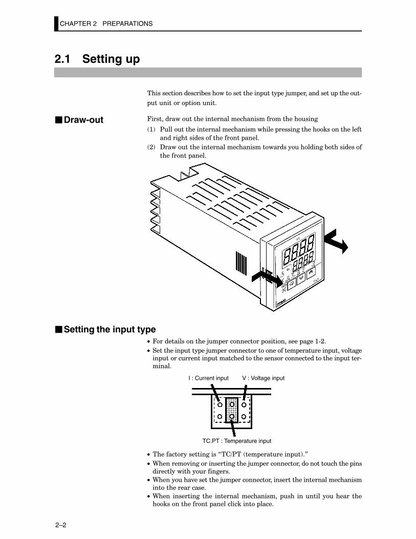
2.1 Setting up
������������������&������������������ ���� ��5� ������������ ������#
�������� ��������
4�������������������������������������������������
:! $���������������������������������� ��������������������������
��������������������������� �����
;! ?���������������������������������������������&����������
��������� �����
�Setting the input typeC• 4����������������5� ����������� ����������� ����:#;�
C• ���������� ���� ��5� ��������������������� ��������� ���.������� ������������� ��������������������������������������� �����#
������
I : Current input V : Voltage input
TC.PT : Temperature input
C• ����������������������7��=$�� ��� ��������� �!�8
C• 9�������.��������������������5� ������������������������� ���
�������������������������
C• 9��������.����������5� �����������������������������������������
������������������
C• 9���� ���������� ���� �������������������� ��� �������� ������� ���
��������������� ��������������� �����
�Draw-out
2.1 Setting up
2–3
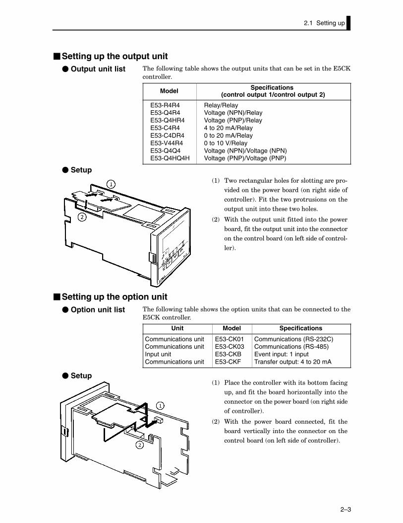
�Setting up the output unit��������������&������������� ����������������&�����������������
���������
Model Specifications(control output 1/control output 2)
E53-R4R4E53-Q4R4E53-Q4HR4E53-C4R4E53-C4DR4E53-V44R4E53-Q4Q4E53-Q4HQ4H
Relay/RelayVoltage (NPN)/RelayVoltage (PNP)/Relay4 to 20 mA/Relay0 to 20 mA/Relay0 to 10 V/RelayVoltage (NPN)/Voltage (NPN)Voltage (PNP)/Voltage (PNP)
� Setup :! ���������������������������������� �#
.����������� ����&���� ��������������
��������!��4���������� �������������
� ������������������������
;! 9��������� ��������������������� ���
&�������������� ���������������������
������������&���� �������������������#
���!�
�Setting up the option unit��������������&������������ ������������������&����������������
��������������
Unit Model Specifications
Communications unitCommunications unitInput unitCommunications unit
E53-CK01E53-CK03E53-CKBE53-CKF
Communications (RS-232C)Communications (RS-485)Event input: 1 inputTransfer output: 4 to 20 mA
� Setup :! $���������������������������&����������
��������������&�������6��������������
�������������� ����&���� ������������
����������!�
;! 9���� ���� ���� &���� ���������� ���� ���
&���� .�������������������������������
������&���� ����������������������!�
� Output unit list
� Option unit list
CHAPTER 2 PREPARATIONS
2–4
2.2 Installation
�Dimensions
5853� 13 100
44.8
48
�
�Panel cutout
45 +0.60
45 +0.60
Unit (mm)65 mm min
60 mm min
C• 3���������� ����� ���������� ���:����
���
C• %������������� ��������.���������������#
6������������� ����&��������������#
�������
�����������������&��������������
.���������������6�������
2.2 Installation
2–5
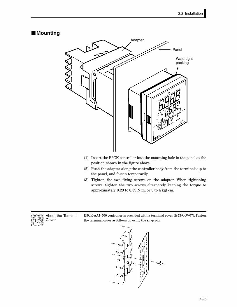
�MountingAdapter
Panel
Watertight packing
:! *�������������������������������������������������� �����������
�������������������������&.��
;! $���������� ����������������������&��������������������� ��
���� �������������������� �������
<! �������� ���� ��� ��1���� ������� �� ���� ��� ����� 9���� ����������
�������� �������� ���� ��� ������� ������������ ��� ���� ���� ��-�� �
� �1��������@�;G���@�<G�+L�����<���,����L���
����#)):#�@@������������� �.����������������������.��� ��<#�2A@>!��4�����
��������������.������������&�������������� � ���
About the TerminalCover
CHAPTER 2 PREPARATIONS
2–6
2.3 Wiring Terminals
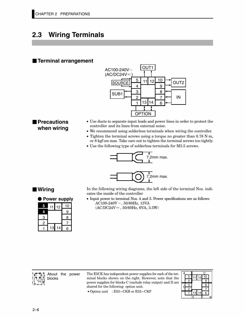
�Terminal arrangement
54321
10987613 14
11 12
OUT1
OUT2
SUB1
OPTION
IN
AC100-240V(AC/DC24V )
SOURCE
C• "������������ �������� ������������ �������������������� �������������������������������������1������������
C• 9�������������������������������������������������������������
C• �������������������������������������-�����������������@�>E�+L����E����L�����1�������������������������������������������������������
C• "����������������� ���������������������������%<����������
7.2mm max.
7.2mm max.
*������������������������������������������������������������+�������#
�������������������������������
C• *� �� ���������������+���,��������$����� �������������������������)�:@@#;,@A ���@=/@B6��:�A) )�=?�;,A ���@=/@B6��/A)��<��9!
����������������� ������� ����� ����������������������#
������ &����� ������� �����������B��.�������� ����� ���
����� ��������&������� �1������������ �!�����?����
����������������������� ��������
C• 2 ������� ����<F��(�����<F��4
About the powerblocks
A C54321
109876
C
D B
11 12
13 14
�Precautionswhen wiring
�Wiring
� Power supply5
432
1
10
9
87
613 14
11 12
2.3 Wiring Terminals
2–7
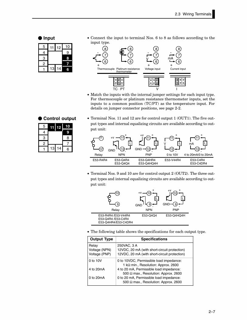
C• ������������� �������������+���/���E�������������������������� ���� ��
8
7
6
8
7
6
8
7
6
8
7
6
-
+
-
+
-
+
V mA
TC ⋅ PT V I
Thermocouple Platinum resistancethermometer
Voltage input Current input
C• %����������� ���������������������5� ���������������������� ���� ��4�������� ����� ������������������������������� ������������� ��� �� �� ����� ������ ��=$�!���� ���� ��� ������� �� ���4�����������5� ����������� ������������ ����;#;�
C• ���������+���::�����:;��������������� ��:� 2"�:!��������.���#
���� �����������������-���6�����������������.����&���������������#
������
11
12
11
12
L
11
12
L
11
12
L
11
12
L
E53-R4R4 E53-Q4R4E53-Q4Q4
E53-Q4HR4E53-Q4HQ4H
E53-V44R4 E53-C4R4E53-C4DR4
NPN PNP 0 to 10V 4 to 20mA/0 to 20mA
+v+
-
+
-
+
-
+
-GND
mA
Relay
V
GND
+v
C• ���������+���G�����:@��������������� ��;� 2"�;!�������������#
���� �����������������-���6�����������������.����&���������������#
������
10
9
10
9
L
10
9
L
+v+
-
+
-GND
E53-Q4Q4 E53-Q4HQ4H
NPN PNP
E53-R4R4 /E53-V44R4E53-Q4R4 /E53-C4R4E53-Q4HR4/E53-C4DR4
Relay
GND
+v
C• ��������������&������������� ��������������������� ���� ��
Output Type Specifications
RelayVoltage (NPN)Voltage (PNP)
250VAC, 3 A12VDC, 20 mA (with short-circuit protection)12VDC, 20 mA (with short-circuit protection)
0 to 10V
4 to 20mA
0 to 20mA
0 to 10VDC, Permissible load impedance: 1 kΩ min., Resolution: Approx. 2600
4 to 20 mA, Permissible load impedance: 500 Ω max., Resolution: Approx. 2600
0 to 20 mA, Permissible load impedance: 500 Ω max., Resolution: Approx. 2600
� Input
5
4
32
1
10
9
87613 14
11 12
� Control output
5
4
3
2
1
10
98
7
613 14
11 12
CHAPTER 2 PREPARATIONS
2–8
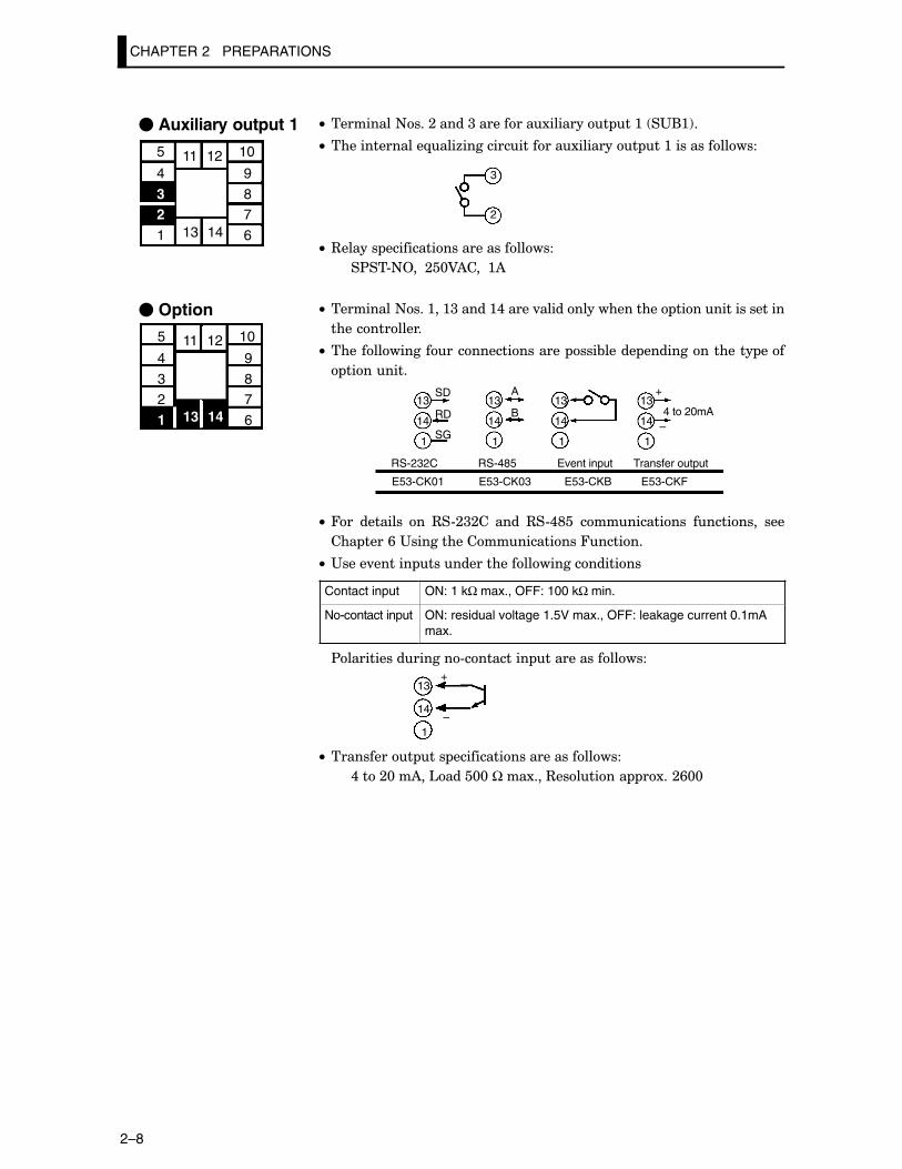
C• ���������+���;�����<���������1�������� ��:� �"(:!�
C• ��������������-���6���������������1�������� ��:�������������
3
2
C• 3������ �������������������������
�$��#+2���;�@A)����:)
C• ���������+���:��:<�����:,�����.������������������ �����������������
�������������
C• ����������������������������� ���&����� ��������������� ���
��������
13
14
1
13
14
1
13
14
1
13
14
1
SD
RD
SG
A
B
+
–4 to 20mA
E53-CK01
RS-232C
E53-CK03
RS-485
E53-CKB E53-CKF
Event input Transfer output
C• 4�� �������� �� 3�#;<;�� ���� 3�#,E�� ������������ ��������� ���
��� ����/�"���������������������4������
C• "����.������ ����������������������������
Contact input ON: 1 kΩ max., OFF: 100 kΩ min.
No-contact input ON: residual voltage 1.5V max., OFF: leakage current 0.1mAmax.
$����������������#��������� ���������������
13
14
1
+
–
C• ���������� ��� �������������������������
,���;@��)��'����@@����1���3�������� �1��;/@@
� Auxiliary output 1
5
4
321
10
9
87
613 14
11 12
� Option
5
4
32
1
10
9
87
613 14
11 12
CHAPTER 3 BASIC OPERATION
3–1
CHAPTER 3BASIC OPERATION
�������� ����������&�������������1�� �����������������������&����
������������������
CHAPTER3
<�: �������1�� �� <F;����������������������������������������������
<�; ��������*� ��� ����������� <F<��������������������������
*� ���� � <F<����������������������������������������������������������
������� <F<����������������������������������������������������������������
<�< ��������2� ��� ����������� <F�����������������������
2� ������������� <F�����������������������������������������
?�����=��.����� ������ <F���������������������������������
������ ���� <F/��������������������������������������������������
<�, ��������)������� � <F>����������������������������������������
)������� � <F>��������������������������������������������������������
)�����.��� <F>������������������������������������������������������
)��������������� <FE����������������������������������������������
�������������= ����������� <FE������������������������
<�� $������%�� <F:@����������������������������������������������������
������� <F:@��������������������������������������������������������������
)=%����� ����� <F:@������������������������������������������������
<�/ ��������������� ����2 ������ <F::����������������
<�> )�5������������2 ������ <F:;������������������������
����������������� ��� <F:;����������������������������������
%����� ������ <F:;��������������������������������������������
)�#������ )���! <F:<������������������������������������������
CHAPTER 3 BASIC OPERATION
3–2
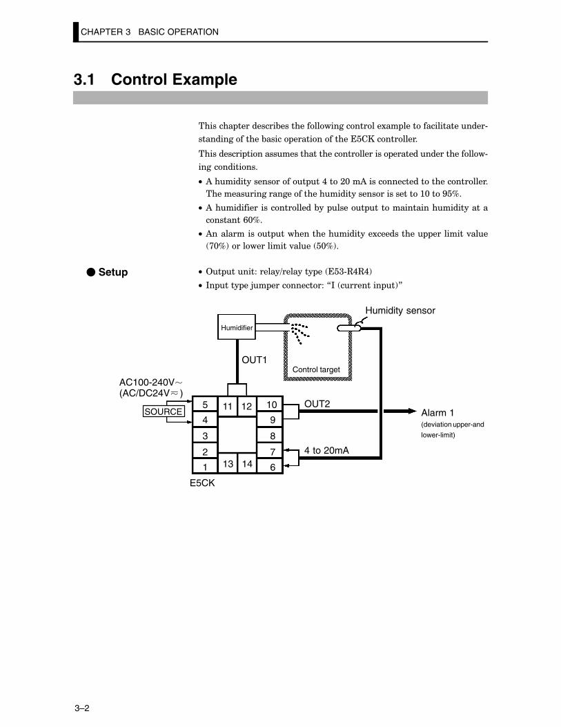
3.1 Control Example
�������� ����������&����������������������1�� ��������������������#
���������������&����� ���������������������������
����������� �������������������������������� ��������������������#
�������������
C• )������������������ ��,���;@��)����������������������������
������������������������������������������������:@���G�D�
C• )�����������������������&�� ����� �������������������������
��������/@D�
C• )������������ ��������������������1���������� ���������.���
>@D!��������������.���� �@D!�
C• 2� ������������=�������� �� ��<#3,3,!
C• *� ���� ��5� ������������7*� ��������� �!8
5
4
3
2
1
10
9
8
7
613 14
11 12
OUT1
OUT2
4 to 20mA
Humidifier
Control target
Humidity sensor
Alarm 1 (deviation upper-and
lower-limit)
E5CK
SOURCE
AC100-240V(AC/DC24V )
� Setup
���������������� ���������������7��8���7�48������� ����������������������
����������������=�4���������8� �����������JMMMMMMK�����JMMMMMMMK�
About the tempera-ture unit
3.2 Setting Input Specifications
3–3
3.2 Setting Input Specifications
C• ���������� ��+�� @���;:!��������7�� ���� �8� ������������������������#
��������7;���:� ������ ��!�8
C• 4�������������� ���� ��������������������������� �����#;;�
C• 9��������.�������� ��������������� �������������������������������
�����������������-�����
C• ����7�������� ��� �����8��7�������� ����� �����8�����7�������� ���8
���������� ��� ����!�������������������
C• ����7�������� ��� �����8� ������������������ ��������-���������&�
�1 �������&������ ���������.�������� �����������7������������������8
������������������ ��������-���������&���1 �������&����������������
.�������� �������7�������� ���8� ��������������������&�����������
���������������� ����
C• ��������������������������������1�� �����,���;@��)��� ���)����
��������� ����������������&�����������������*�����������������7�������
���8� ������������������7:8�
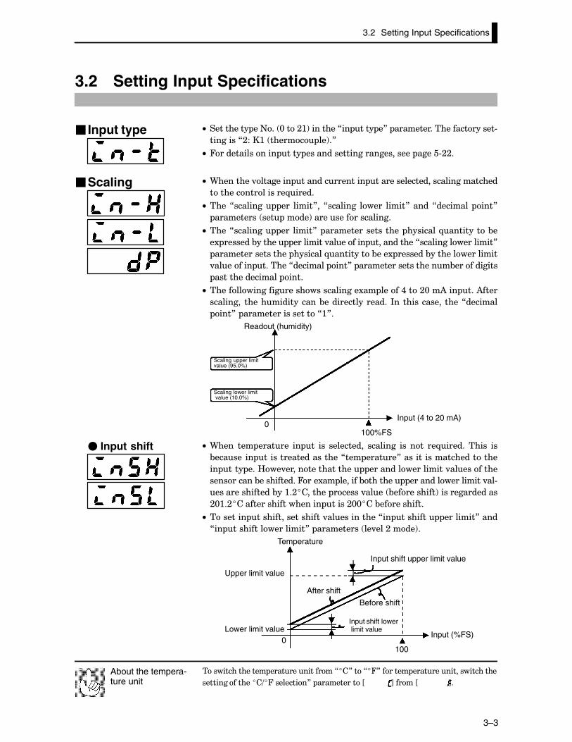
100%FS0
Readout (humidity)
Scaling upper limit value (95.0%)
Scaling lower limit value (10.0%)
Input (4 to 20 mA)
C• 9���� ��� ������� �� �� ��� ���������� �������� ��� ��� ��-����������� ��
&������ �� ��������������������7��� ������8�����������������������
�� ���� ���B��.����������������� ������������������.����������
����������&�����������4���1�� �������&������� ������������������.��#
���������������&��:�;�������� ������.���� &����������!���������������
;@:�;���������������������� �����;@@���&�����������
C• �������� �������������������.������������7�� �������� ��������8����
7�� ������������������8� ���������� ��.���;����!�
0100
Temperature
Upper limit value
Lower limit value
Input shift upper limit value
After shift
Before shift
Input shift lower limit value
Input (%FS)
� Input type
�Scaling
� Input shift
CHAPTER 3 BASIC OPERATION
3–4
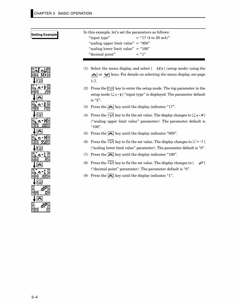
*��������1�� �������0���������� �������������������
7�� ���� �8 N�7:>� ,���;@��)!8
7�������� ���������.���8 N�7G�@8
7�������������������.���8 N�7:@@8
7�������� ���8 N�7:8
:! ������������������ ����������������JMM K� ��� ����!���������
��� �������4��������������������������������� ��������� ���
:#>�
;! $��������� �������������������� ����������� � ���������������
��� �����J K�7�� ���� �8������� ����������� ���������������
���7;8�
<! $��������� ����������������� ��������������7:>8�
,! $��������� ���������1���������.������������ ��������������J K
7�������� ��� ������ .���8� ��������!������ ���������������� ��
7:@@8�
�! $��������� ����������������� ��������������7G�@8�
/! $��������� ���������1���������.������������ ��������������J K
“�������������������.���8� ��������!������ �������������������7@8�
>! $��������� ����������������� ��������������7:@@8�
E! $��������� ���������1���������.������������ ��������������JCCCCC K
7�������� ���8� ��������!������ �������������������7@8�
G! $��������� ����������������� ��������������7:8�
Setting Example
3.3 Setting Output Specifications
3–5
3.3 Setting Output Specifications
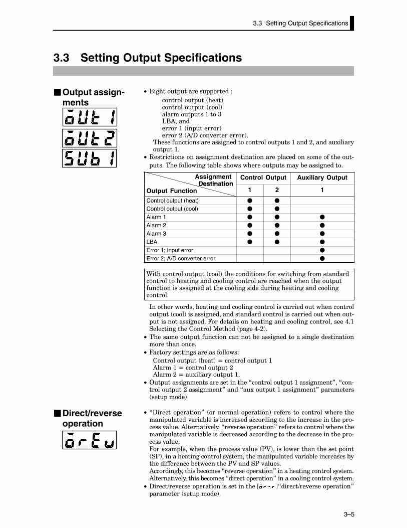
C• ������� ������� ������
������� �� ����!������� �� ��!������� ���:���<'()����������:� �� ������!�����;� )=?���.����������!�
������������������������������������ ���:�����;�������1������� ��:�
C• 3��������������������������������������� �������������������#
������������������&��������������� �������&�������������
AssignmentDestination
Control Output Auxiliary OutputDestination
Output Function 1 2 1
Control output (heat) � �
Control output (cool) � �
Alarm 1 � � �
Alarm 2 � � �
Alarm 3 � � �
LBA � � �
Error 1; Input error �
Error 2; A/D converter error �
9����������� �� ��!��������������������������������������������������������������������������������������������� �������������������������������������������������������������������
*������������������������������������������������������������� �� ��!����������������������������������������������������# ������������������4�����������������������������������������,�:��������������������%����� ����,#;!�
C• ���������� ����������������&���������������������������������������������
C• 4����������������������������
������� �� ����!�N�������� ��:)�����:�N�������� ��;)�����;�N��1�������� ��:�
C• 2� �����������������������������7������� ��:�����������8��7��#����� ��;�����������8�����7�1�� ��:�����������8� ��������� ��� ����!�
C• 7?������ ������8� �������� ������!� ������� �� ������������������� ������.����&����������������������������������������������� �#�����.�����)��������.�����7��.����� ������8����������������������������� ������.����&����������������������������������������������� �#�����.����4���1�� ������������� ������.���� $A!����������������������� ��� �$!������������������������������������� ������.����&�������������&����������������&�����������$A������$�.�����)����������������&������7��.����� ������8���������������������������)��������.����������&������7������� ������8�������������������������
C• ?�����=��.����� ���������������������J K7������=��.����� ������8 ��������� ��� ����!�
�Output assign-ments
�Direct/reverseoperation
CHAPTER 3 BASIC OPERATION
3–6
C• 9��������� ��������� ����� ���������������� ����������� ���
� �������� ������ ����!���������������� ���� ����� �.����
&������������ ��������������������� ����������&����������������
������1 ��������������� �������������������������������� �
�������������
C• ���������� �������������������7������ ����� ����!8� ��������� ��.��
:����!��4�����������������7;@�;@��������8
*��������1�� �������0���������� �������������������
7������� ��:�����������8 N�7������� �� ����!8
7������� ��;�����������8 N�7������� ��:8
7������=��.����� ������8 N�7��.����� ������8
7������ ����8 N�7;@�������8
)����������&.��������������������1�� ����������������������������������
�1�� �������������������������������� ������������������
:! ������������������ ����������������JCCC K� ��� ����!���������
��� �������4��������������������������������� ��������� ���
:#>�
;! $��������� �������������������� ����������� � ���������������
��� �����J K�7�� ���� �8������� �������*��������1�� �������
��������������������7:>��,���;@��)�8
<! $����� ���� � ���� ����� J K� 7������ � �� :� ����������8
��������!������� ����������� �������������������J K�
,! )�����������������������1�� ��������&����������������� ��������� �����
���� ��� ���� �������� �� J K� 7������ � �� ;� ����������8
��������!������ �������������������J K�
�! )�����������������������1�� ��������&����������������� ��������� ����
����� J K� 7������=��.����� ������8� ��������!� ��� ��� ������
���� �������������������J K�
/! )�����������������������1�� ��������&����������������� ��������� ���
��������������J K� ��.���:����!��4�����������������������������
��� ��������� ����:#>�
>! $��������� �������������������.���:����������� � ���������������
��.���:�����JCCCC K�7)���1����=������8������� ������
E! $��������� ����������JCCCC K� 7������ ����8� ��������!�������#
����������� �������������������7;@8��)�����������������������1�� ��
�����&�����������������-������� �������
�Control period
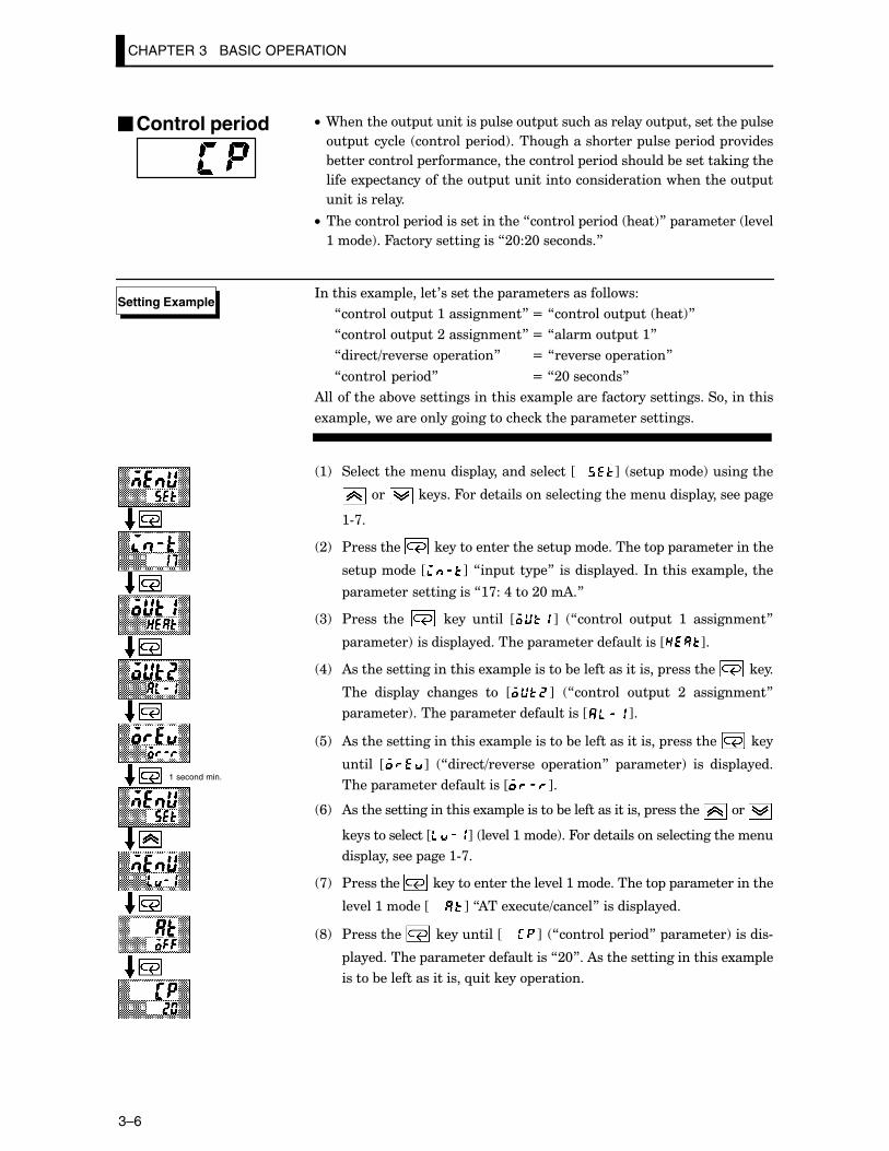
Setting Example
1 second min.
3.4 Setting Alarm Type
3–7
3.4 Setting Alarm Type
C• ������������� �������� �������������:���<��2����������������
����������������������� ������&������
C• )������ �������������������������������������������&������
������7�������� �8��7������.���8�����7����������������8� ��������
���������
C• �������������������������������� �����2+�����&��������7 ��8
��7�����8��������7�������������= �����������8� ���������
C• ��������������&�������������������� ���� �����&�������������#
�������������������� ����.�� ��������
Alarm TypeAlarm Output Operation
Alarm TypeWhen X is positive When X is negative
1 Upper-and lower-limit alarm (deviation)
ONOFF
X X
SPAlways ON
2 Upper-limit alarm (deviation) ONOFF
X
SP
ONOFF
X
SP
3 Lower-limit alarm (deviation) ONOFF
X
SP
XONOFF
SP
4 Upper-and lower-limit rangealarm (deviation)
ONOFF
X X
SPAlways OFF
5Upper-and lower-limit alarmwith standby sequence (deviation)
ONOFF
X X
SPAlways OFF
6 Upper-limit alarm withstandby sequence (deviation)
ONOFF
X
SP
ONOFF
X
SP
7 Lower-limit alarm withstandby sequence (deviation)
ONOFF
X
SP
ONOFF
X
SP
8 Absolute-value upper-limitalarm
ONOFF
X
0
ONOFF
X
0
9 Absolute-value lower-limitalarm
ONOFF
X
0
ONOFF
X
0
10 Absolute-value upper-limitalarm with standby sequence
ONOFF
X
0
ONOFF
X
0
11 Absolute-value lower-limitalarm with standby sequence
ONOFF
X
0
ONOFF
X
0
C• )������� ��������������� ������������������������������7������:���<8 ���������� ��� ����!��4�����������������7;��" ��#������������ ��.�#
����!8�
C• )�����.��������� ����������&��7O8� ��� ���� ��&����&.���)������ �
��������������������������������������.������������������� ����.�
��������.��
C• )�����.����������������� ������������������������������7������.���
:���<8� ���������� ��.���:����!��4�����������������7@8�
�Alarm type
�Alarm value
CHAPTER 3 BASIC OPERATION
3–8
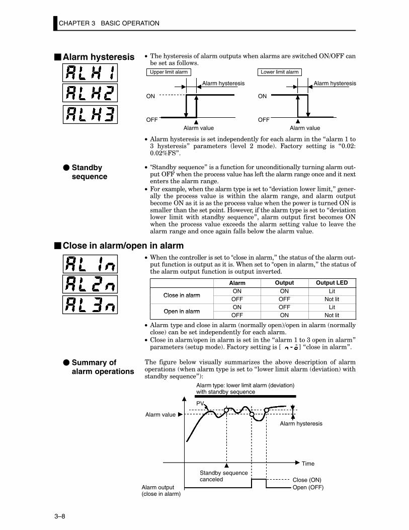
C• ������������������������ ����������������������������2+=244����&���������������
ON
OFF
Alarm hysteresis
Alarm value Alarm value
ON
OFF
Upper limit alarm Lower limit alarm
Alarm hysteresis
C• )��������������������������� ������������������������������7������:��<� ����������8� ���������� ��.��� ;� ���!�� 4������ �������� ��� 7@�@;�@�@;D4�8�
C• “�����&����-����8�������������������������������������������# ��244���������� ������.������������������������������������������1������������������������
C• 4���1�� ��������������������� �����������“��.�����������������8������#����� ���� ������ .���� ��� ������� ���� ������ ������� ���� ������ � �&�����2+����������������� ������.������������� �������������2+������������������������ �����B��.������������������� �����������7��.���������� ����������� �����&�� ��-����8�� ������� �� ������&������2+����� ���� ������.���� �1������ ������������������.���� �� ���.�� �����������������������������������&��������������.����
�Close in alarm/open in alarmC• 9��������������������������“��������������8������������������������#
������������� ������������9����������“ ������������8����������������������� ������������� ����.������
Alarm Output Output LED
Close in alarmON ON Lit
Close in alarmOFF OFF Not lit
Open in alarmON OFF Lit
Open in alarmOFF ON Not lit
C• )������� �������������������� �������� ��!= ������������ �����������!�����&���������� �����������������������
C• �������������= ��������������������������7������:���<� �����������8 ���������� ��� ����!��4�����������������JCC K�7�������������8�
���� ������ &���� .������� ������6��� ���� �&.�� ������ ���� �� ����� �������� ������������� �����������7����������������� ��.�����!����������&����-����8!�
Alarm type: lower limit alarm (deviation)with standby sequence
Alarm value
Alarm output (close in alarm)
Standby sequencecanceled
PV
Alarm hysteresis
Time
Close (ON)Open (OFF)
�Alarm hysteresis
� Standbysequence
� Summary ofalarm operations
������������ ����������������.�������������������������������7�������� ���8
��������� ��� ����!��*��������1�� ��������7�������� ���8� �����������������
7:8�� ?�������� ��������� ��������������� ����������������.������������
��������������!
About the DecimalPoint of the AlarmValue
3.4 Setting Alarm Type
3–9
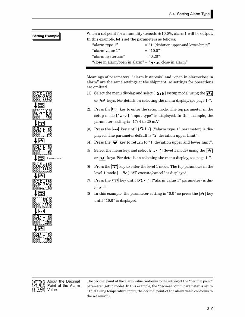
9���������� ������������������1�������:@�@D�������:������&��� ��
*��������1�� �������0���������� �������������������
7�������� ��:8 N�7:�� ��.������ ��#��������#�����!8
7������.����:8 N�7:@�@8
7����������������8 N�7@�;@8
7�������������= �����������8N�7 ���������������8
%���������� �����������7����������������8�����7 �����������=�������
�����8��������������������������������� �������������������� �������
�����������
:! ������������������ ����������������JCC K� ��� ����!����������
�� �������4��������������������������������� ��������� ����:#>�
;! $��������� �������������������� ����������� � ���������������
��� �����J K�7�� ���� �8������� �������*��������1�� �������
��������������������7:>��,���;@��)8�
<! $��������� ����������J K� 7�������� ��:8� ��������!�������#
����������� �������������������7;����.������ ��������8�
,! $��������� ���������������7:����.������ �����������������8�
�! �������������������������������J K� ��.���:����!����������
�� �������4��������������������������������� ��������� ����:#>�
/! $��������� �������������������.���:����������� � ���������������
��.���:�����JCCCC K�7)���1����=������8������� ������
>! $��������� ����������J K� 7������.����:8� ��������!�������#
������
E! *��������1�� �������� ��������������������7@�@8��� ��������� ����
�����7:@�@8������� ������
Setting Example
1 second min.
CHAPTER 3 BASIC OPERATION
3–10
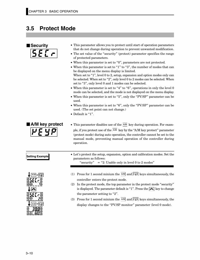
3.5 Protect Mode
C• ����� ������������������� ������������������� ������� ���������
����������������������� ��������� ��.�����������������������
C• ��������.����������7�������8� �����!� ���������� �����������������
�� �������� ����������
C• 9��������� ������������������7@8�� ����������������� ��������
C• 9��������� ������������������7:8���7<8��������&������������������
&����� ������������������� ���������������
9����������7:8����.���@���;����� ���1 ���������� ����������������
&������������9����������7;8��������.���@���;����������&������������9���
������7<8��������.���@�����:����������&�����������
C• 9��������� ������������������7,8���7/8�� ���������������������.���@
��������&��������������������������������� ������������������� ����
C• 9��������� ������������������7�8����������7$A=�$8� �������������&�
����
C• 9��������� ������������������7/8����������7$A=�$8� �������������&�
����� �������� ������������������!
C• ?���������7:8�
C• ����� �������������&������������� A/M ����������� ��������4���1��#
��������� ��������������� A/M �����&������7)=%����� �����8� ��������
���������!���������� ���������������������������&�����������
����������� ��.������������� ������� �� ���� ��������������
�������
• '��0�� ������������� ���1 ������� ������������&�������������������
�������������������
7�������8 N�7;��"��&������������.���@���;�����8
:! $��������:����������������� A/M ����� ����������������������
�������������������� ����������
;! *������ ���������������� � ���������������� ����������7�������8
������ ����������� �������������������7:8��$��������� �������������
���� �������������������7;8�
<! $��������:����������������� A/M ����� ����������������������
��� ������������������7$A=�$������8� ��������� ��.���@����!�
�Security
�A/M key protect
Setting Example
A/M
A/M
3.6 Starting and Stopping Operation
3–11
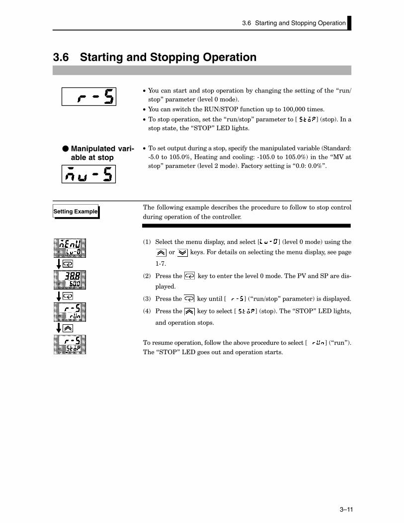
3.6 Starting and Stopping Operation
C• I����������������� � �������&�����������������������������7��=
�� 8� ��������� ��.���@����!�
C• I����������������3"+=��2$�������� ���:@@�@@@�������
C• ���� � ����������������7��=�� 8� �����������JC K� �� !��*���
�� ������������7��2$8�'�?��������
C• ������� ������������ ��� �������������� ������.����&��� ���������
#��@���:@��@D��B������������������#:@��@���:@��@D!��������7%A���
�� 8� ��������� ��.���;����!��4�����������������7@�@��@�@D8�
���� ���������1�� ���������&������� ������������������ ������
������ ����������������������
:! ������������������ ����������������J K� ��.���@����!���������
��� �������4��������������������������������� ��������� ���
:#>�
;! $��������� �������������������.���@����������$A������$��������#
������
<! $��������� ����������JCCC K� 7��=�� 8� ��������!������� ������
,! $��������� ��������������JC K� �� !������7��2$8�'�?��������
���� ��������� ��
�������� ������������������&.�� ����������������JCCC K� 7��8!�
����7��2$8�'�?����������� ��������������
� Manipulated vari-able at stop
Setting Example
�� ��.����������������������������� ������.����&������������������&������
������������� �������� ��������������������������.�����������������.�
������������&����� �����������������������������.�������&�������������
������������.���������������������� ��������������������
Balance-less,Bump-less Opera-tion
CHAPTER 3 BASIC OPERATION
3–12
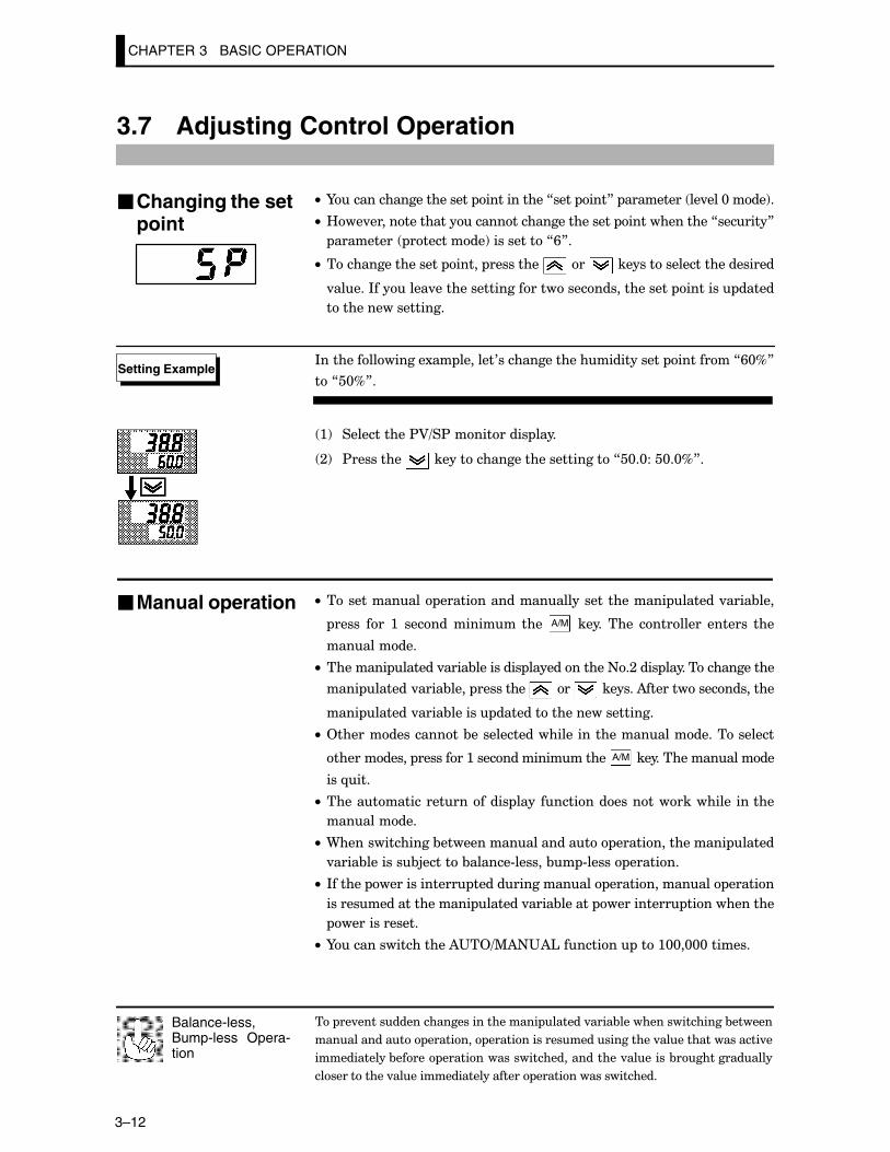
3.7 Adjusting Control Operation
C• I�������������������� �����������7���� ���8� ��������� ��.���@����!�
C• B��.������������������������������������ �������������7�������8
��������� ���������!����������7/8�
C• ����������������� ����� ��������� ��� ��������������������������
.�����*�������.������������������������������������ ������� �����
������������������
*���������������1�� �������0������������������������� ��������7/@D8
��7�@D8�
:! �����������$A=�$���������� ����
;! $��������� ����������������������������7�@�@���@�@D8�
C• ������������ ������������������������������� ������.����&���
����� ��� :� ������ ������� ���� A/M � ����� ���� ��������� ������� ���
����������
C• �������� ������.����&��������� ������������+�;���� �����������������
���� ������.����&���� ��������� ��� �������)�������������������
���� ������.����&������ ������������������������
C• 2����������������&�������������������������������������������
����������� ��������:������������������ A/M �������������������
���-���
C• ����������������������� ���� ������������������������ ������
����������
C• 9��������������&�������������������� ���������������� �����
.����&�������&5������&������#������&� #����� �������
C• *������ ������������� ���������������� �������������� ������
��������������������� ������.����&������ ���������� ������������
�������������
C• I����������������)"�2=%)+")'�������� ���:@@�@@@�������
�Changing the setpoint
Setting Example
�Manual operation
3.7 Adjusting Control Operation
3–13
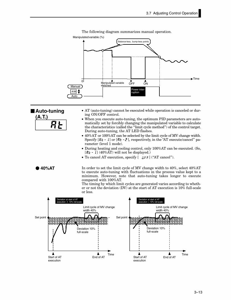
��������������������������6��������� �������
OFF ON
A/M
0
Manipulated variable (%)Balance-less, bump-less points
Manual
Auto
TimeManipulated variableswitched
Power inter-ruption
C• )�� ��#�����!�������&���1������������ �����������������������#����2+=244�������
C• 9�������1�������#����������� �����$*?� ����������������#��������������&������&�������������������� ������.����&��������������������������������� �����������7�����������������8!��������������������?�������#�����������)��'�?���������
C• ,@D)����:@@D)������&�����������&��������������������%A��������������� ������J K���J K����� ����.������������“)���1����=������8� �#�������� ��.���:����!�
C• ?����������������������������������:@@D)������&���1������� ��J K� ,@D)�!���������&����� ������!
C• ���������)���1�������� ������JCCC K� 7)��������8!�
*�������������������������������%A����������������,@D���������,@D)����1�������#���������������������������� ������.������ ������������� B��.���� ���� ����� ��#������ ������ ������ �� �1������ ����������:@@D)�������������&�����������������������������������.����������������������#��������������.������ ?A!����������������)���1���������:@D����#������������
Deviation at start of ATexecution � 10% full-scale
Deviation at start of ATexecution < 10% full-scale
Limit cycle of MV changewidth 40%
Limit cycle of MV changewidth 40%
Set point Set point
Start of ATexecution
End of AT Start of ATexecution
End of ATTime Time
Deviation 10%full-scale
Deviation 10%full-scale
�Auto-tuning(A.T.)
� 40%AT
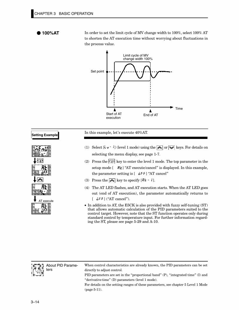
9������������������������������������������������$*?� ��������������&�����
�������������5���������
$*?� �������������������������7 � �������&���8� $!��7���������������8� *!����
7����.���.������8� ?!� ���������� ��.���:����!�
4��������������������������������������� ������������������ ������'�.���:�%��
�����#::!�
About PID Parame-ters
CHAPTER 3 BASIC OPERATION
3–14
*�������������������������������%A����������������:@@D���������:@@D�)�
�������������)���1��������������������������&��������������
���� ������.����
Set point
Start of ATexecution
End of AT
Time
Limit cycle of MVchange width 100%
*��������1�� �������0���1�����,@D)��
:! �������J K� ��.���:����!���������� ��� �������4�����������
��������������������� ��������� ����:#>�
;! $��������� �������������������.���:����������� � ���������������
��� �����JCCCC K�7)���1����=������8������� �������*��������1�� ���
���� ��������������������JCCC K�7)��������8
<! $��������� �������� ������J K�
,! ����)��'�?��������������)���1��������������9��������)��'�?����
�� ������)���1�����!�� ���� �����������������������������
JCCC K� 7)��������8!�
C• *������������)������������������� �.�����������66������#������ ��!�����������������������������������$*?� �����������������������������������B��.��������������������������� �������������������������������&����� ��������� ���4�������������������������#������������ ���������� �����#;G�����)#:@�
� 100%AT
Setting Example
AT execute
CHAPTER 4 APPLIED OPERATION
4–1
CHAPTER 4APPLIED OPERATION
�������� ����������&�������������� ������������-������������������
�����������������������������3������������ �������������������������
��������������� ����������� ������
CHAPTER4
,�: ��������������������%���� ,F;������������������������
B���������������������� ,F;��������������������������
2+=244������ ,F<����������������������������������������������
,�; 2 ����������������3���������� ,F,����������������
%��� ������.����&�������������� ,F,����������������
���� ����������� ,F�����������������������������������������������
�$���� ,F�������������������������������������������������������������
,�< B����"���2 ����4������ ,F>����������������������
�.������ � ,F>������������������������������������������������������
���������� � ,FE������������������������������������������������
,�, '() ,FG��������������������������������������������������������������������
,�� ����&����� ,F::��������������������������������������������������������
����&������������� �� ,F:;������������������������������
����&������� �������
��������������������� ,F:�����������������������������������
����&���������������� � ,F:>������������������������������
����&�������.�������� � ,F:E������������������������������
�������������������������� ,F;@������������������������
CHAPTER 4 APPLIED OPERATION
4–2
4.1 Selecting the Control Method
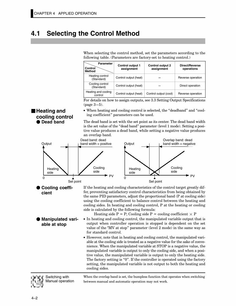
9��������������������������������������� ������������������������
����������&���� $��������������������#��������������������!
Parameter
Control Method
Control output 1assignment
Control output 2assignment
Direct/Reverseoperations
Heating control(Standard) Control output (heat) – Reverse operation
Cooling control(Standard) Control output (heat) – Direct operation
Heating and coolingcontrol Control output (heat) Control output (cool) Reverse operation
4������������������������� ��������<�<���������2� ��� �����������
����<F�!�
C• 9���������������������������������������������7����&���8�����7��#
��������������8� ��������������&������
���������&������������������������ ����������������������������&���������
�����������.����������7�����&���8� ��������� ��.���:����!������������ ��#
��.��.���� �������������&���������������������������.��.���� ��������.���� �&����
0 PV 0 PV
Output OutputDead band: deadband width = positive
Overlap band: deadband width = negative
Heatingside
Heatingside
Coolingside
Coolingside
Set point Set point
*����������������������������������������������������������������������#
����� ��.���������������������������������������������&�����&�������&����������$*?� �������������5������� � �������&���� $��������������!
����������������������������&�������������&����������������������
�������������*���������������������������$�����������������������
������������������&��������������������
B������������$�N�$P������������$�N��������������������$
C• *����������������������������������� ������.����&���� ���������
� ���������������� ������� ��� �� ��� ����� ��������� ���� ���
.����������“%A������ 8� ��������� ��.���;����!�������������������
������������������
C• B��.������������������������������������������������� ������.���#
�&�������������������������������������������.��.��������������������.�#��������9������������ ������.����&��������2$������������.��.��������
���� ������.����&������� ����������������������������������� ��#
��.��.������������� ������.����&������� �������������������������
����������������������7@8��*������������������ ����������������������
����������������� ������.����&���������� ����&������������������������������
9��������.���� �&����������������&� ����������������� ���������������������
&������������������������� ������������������
Switching withManual operation
�Heating andcooling control� Dead band
� Cooling coeffi-cient
� Manipulated vari-able at stop
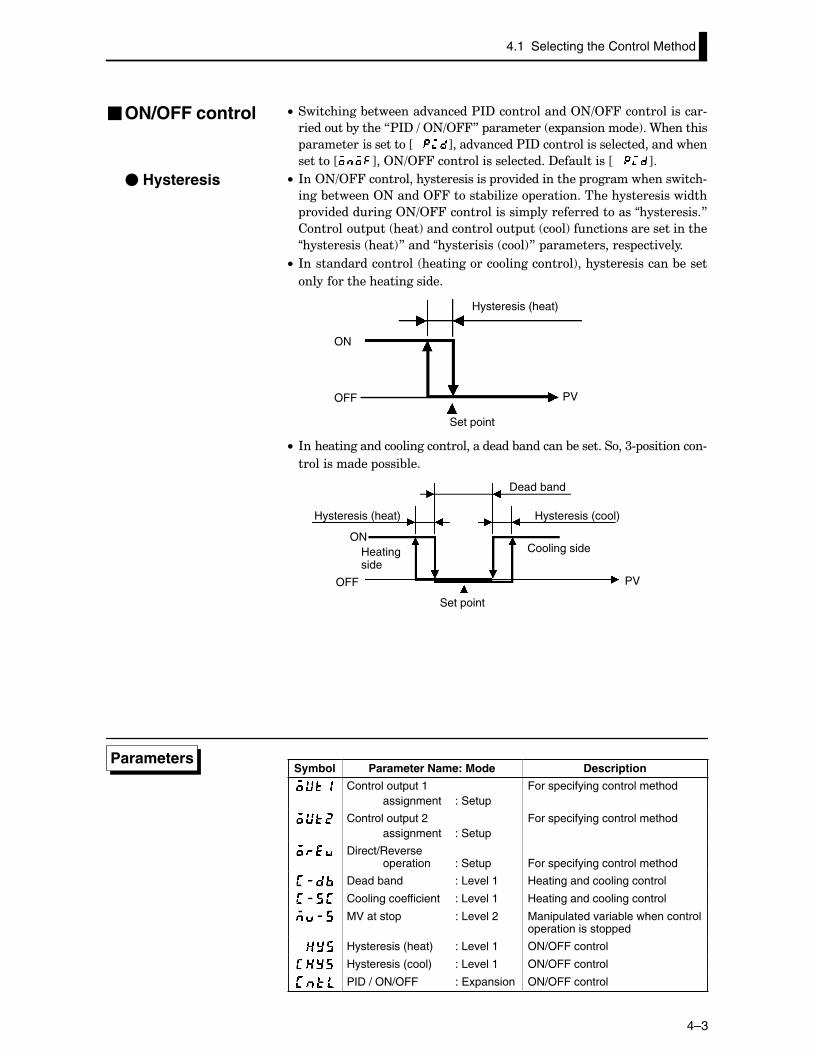
4.1 Selecting the Control Method
4–3
C• ����������&���������.������$*?�����������2+=244�������������#
�������&������7$*?�=�2+=2448� ��������� �1 ���������!��9��������
������������������JCCC K����.������$*?����������������������������
������J K��2+=244��������������������?���������JCCC K�
C• *��2+=244���������������������� �.������������ �����������������#
����&�������2+�����244������&���6�� ����������������������������
�.�����������2+=244������������� �����������������“�����������8
������� �� ����!������������ �� ��!�����������������������
“����������� ����!8�����“����������� ��!8� �������������� ����.����
C• *����������������� ���������������������!�����������������&�����
������������������������
ON
OFF PV
Hysteresis (heat)
Set point
C• *����������������������������������&��������&����������<# ��������#
������������ ���&���
ON
OFF PV
Hysteresis (heat)
Heatingside
Set point
Cooling side
Hysteresis (cool)
Dead band
Symbol Parameter Name: Mode Description
Control output 1assignment : Setup
For specifying control method
Control output 2assignment : Setup
For specifying control method
Direct/Reverseoperation : Setup For specifying control method
Dead band : Level 1 Heating and cooling control
Cooling coefficient : Level 1 Heating and cooling control
MV at stop : Level 2 Manipulated variable when controloperation is stopped
Hysteresis (heat) : Level 1 ON/OFF control
Hysteresis (cool) : Level 1 ON/OFF control
PID / ON/OFF : Expansion ON/OFF control
�ON/OFF control
� Hysteresis
Parameters
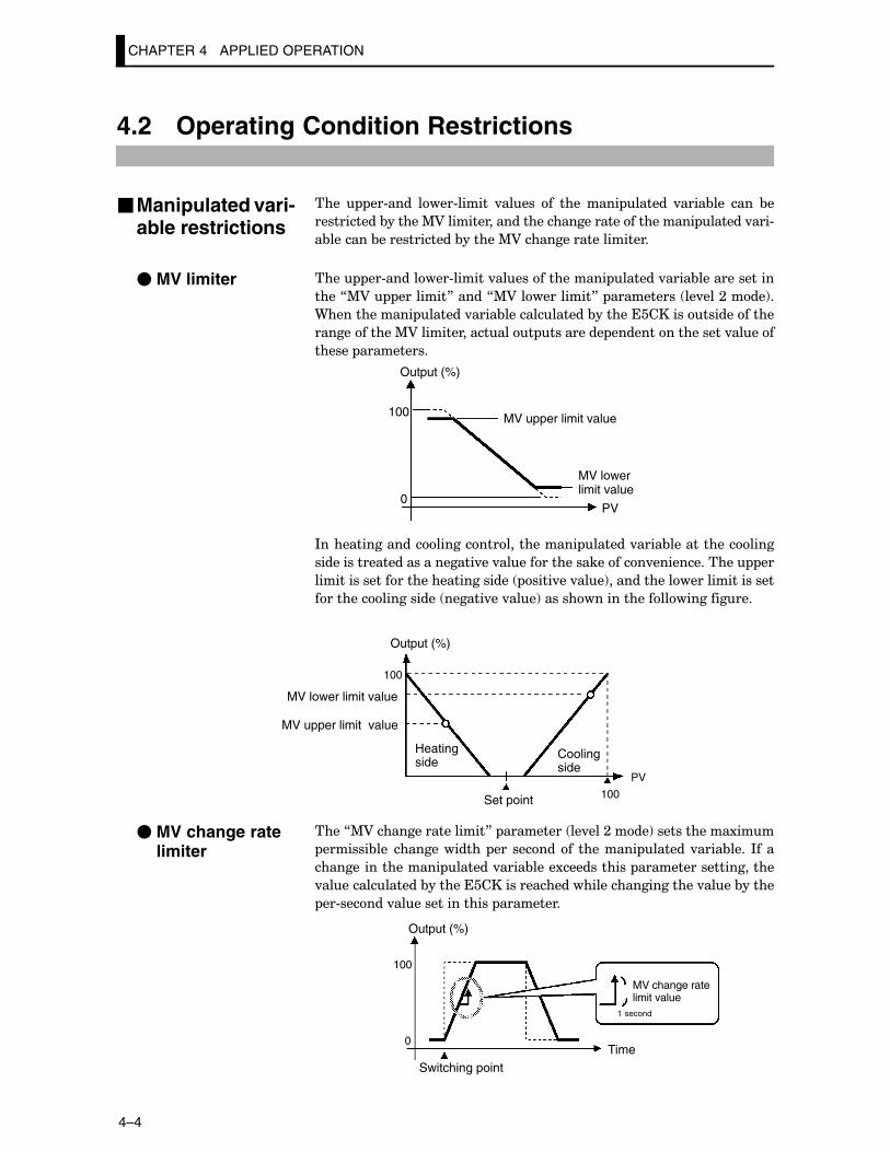
CHAPTER 4 APPLIED OPERATION
4–4
4.2 Operating Condition Restrictions
���� ��#���� ����#������ .����� �� ���� ���� ������ .����&��� ���� &�
�����������&������%A���������������������������������������� ������.���#
�&�������&�������������&������%A���������������������
���� ��#��������#������.��������������� ������.����&�������������
����7%A� ��������8�����7%A�����������8� ���������� ��.���;����!�
9������������ ������.����&�������������&�������������������������
������������%A����������������� ��������� �����������������.�����
������ ����������
100
0PV
Output (%)
MV upper limit value
MV lowerlimit value
*����������������������������������� ������.����&���������������
���������������������������.��.��������������������.������������� ��
��������������������������������� ����.��.���!���������������������������
������������������ ������.��.���!������������������������������
100
100
PV
Output (%)
MV upper limit value
MV lower limit value
Heatingside
Set point
Coolingside
����7%A������������������8� ��������� ��.���;����!������������1���
�������&��� ������������� ��� �������� �������� ������.����&���� *���
������������������ ������.����&����1����������� ���������������������
.��������������&�����������������������������������������.����&�����
��#������.���������������� ���������
100
0
Output (%)
Switching pointTime
MV change ratelimit value
1 second
�Manipulated vari-able restrictions
� MV limiter
� MV change ratelimiter
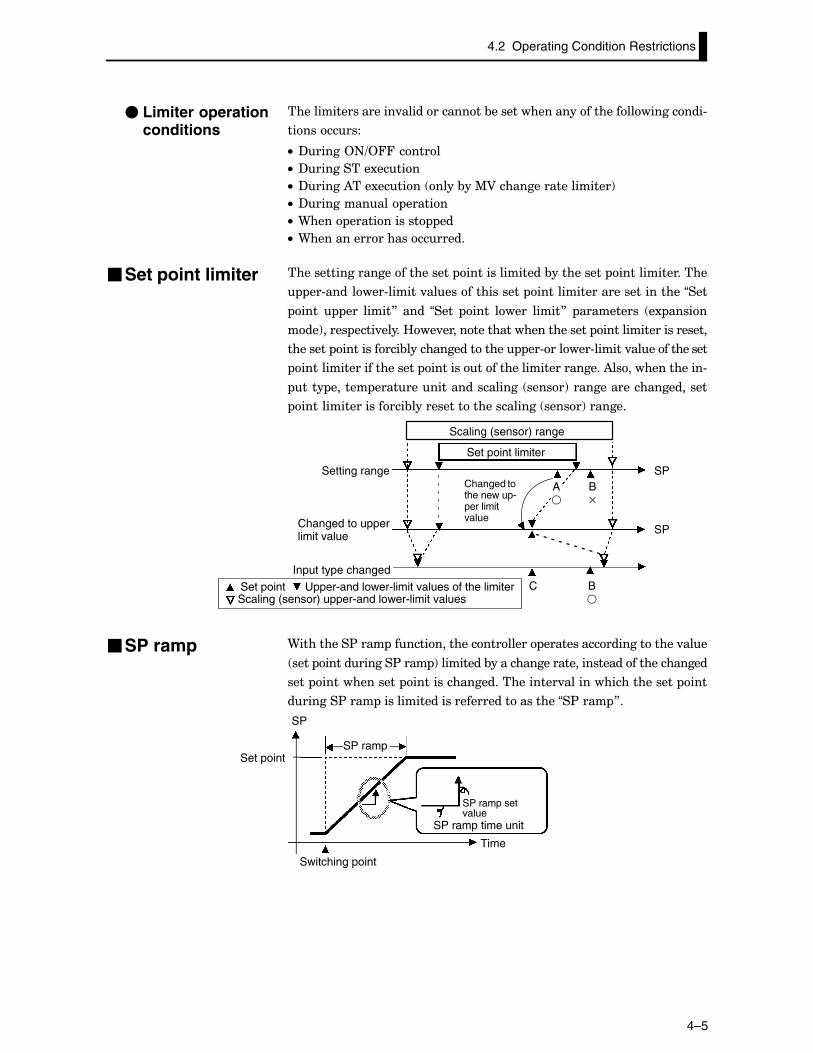
4.2 Operating Condition Restrictions
4–5
�������������������.�������������&���������������������������������#
����������
C• ?�����2+=244������
C• ?���������1�����
C• ?�����)���1������ ����&��%A��������������������!
C• ?����������� ������
C• 9���� ������������ ��
C• 9�����������������������
���������������������������� ���������������&���������� ����������������
��#��������#������.���������������� ���������������������������“���
���� ��� �����8� ���� “���� ���� ����� �����8� ���������� �1 �����
���!����� ����.�����B��.�������������������������� ���������������������
�������� �����������&����������������� ��#������#������.�������������
����������������������� ������������������������������)���������������#
���� ������ ����������������������� �����!�����������������������
�������������������&����������������������� �����!�������
Scaling (sensor) upper-and lower-limit values
Changed tothe new up-per limitvalue
Scaling (sensor) range
SP
Set point Upper-and lower-limit values of the limiter
Set point limiter
Setting range
Changed to upperlimit value
Input type changed
SP
A�
B�
C B�
9���������$���� ���������������������� ����������������������.���
���� �����������$���� !���������&��������������������������������������
���� ������������� �������������������������.�������������������� ���
�������$���� ���������������������������������“�$���� 8�
SP
Set pointSP ramp
SP ramp setvalue
SP ramp time unit
Time
Switching point
� Limiter operationconditions
�Set point limiter
�SP ramp
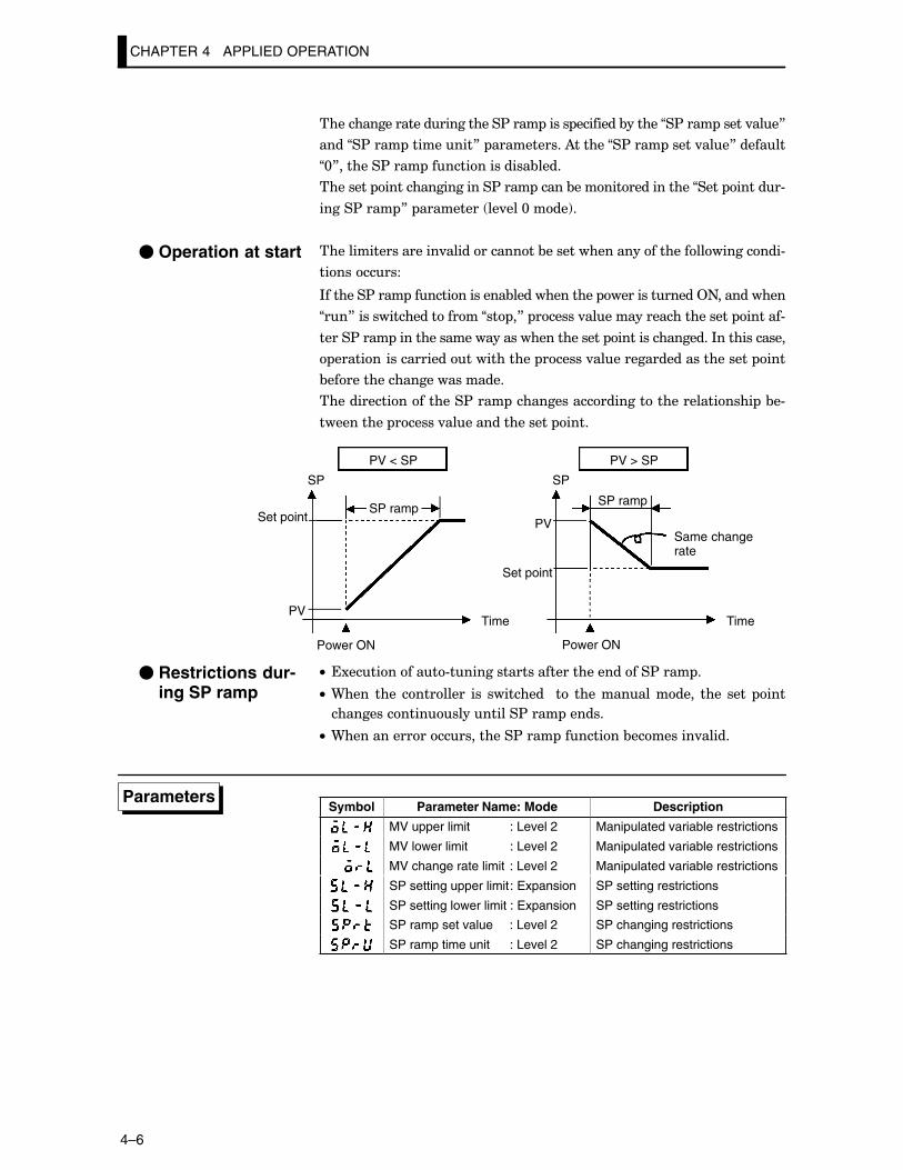
CHAPTER 4 APPLIED OPERATION
4–6
���������������������������$���� ����� ��������&������“�$���� �����.���8
����“�$���� ���������8� �����������)������“�$���� �����.���8�������
“@8�������$���� ���������������&����
�������� �����������������$���� �����&�����������������“���� ������#
�����$���� 8� ��������� ��.���@����!�
�������������������.�������������&���������������������������������#
����������
*�������$���� ��������������&������������� �������������2+����������
“��8�������������������“�� �8� ������.���������������������� ������#
�����$���� ��������������������������������� ����������������*������������
����������������������������� ������.������������������������ ���
&�������������������������
��������������������$���� ���������������������������������� �&�#
���������� ������.���������������� ����
SP
PV
SP
PV
PV < SP PV > SP
Set pointSP ramp
SP ramp
Same changerate
Set point
Power ON
Time Time
Power ON
C• �1����������#������������������������������$���� �
C• 9���� ���� ��������� ��� ��������� � �� ��������������� ���� ���� ���
�����������������������$���� ������
C• 9�����������������������$���� ��������&��������.�����
Symbol Parameter Name: Mode Description
MV upper limit : Level 2 Manipulated variable restrictions
MV lower limit : Level 2 Manipulated variable restrictions
MV change rate limit : Level 2 Manipulated variable restrictions
SP setting upper limit: Expansion SP setting restrictions
SP setting lower limit : Expansion SP setting restrictions
SP ramp set value : Level 2 SP changing restrictions
SP ramp time unit : Level 2 SP changing restrictions
� Operation at start
� Restrictions dur-ing SP ramp
Parameters
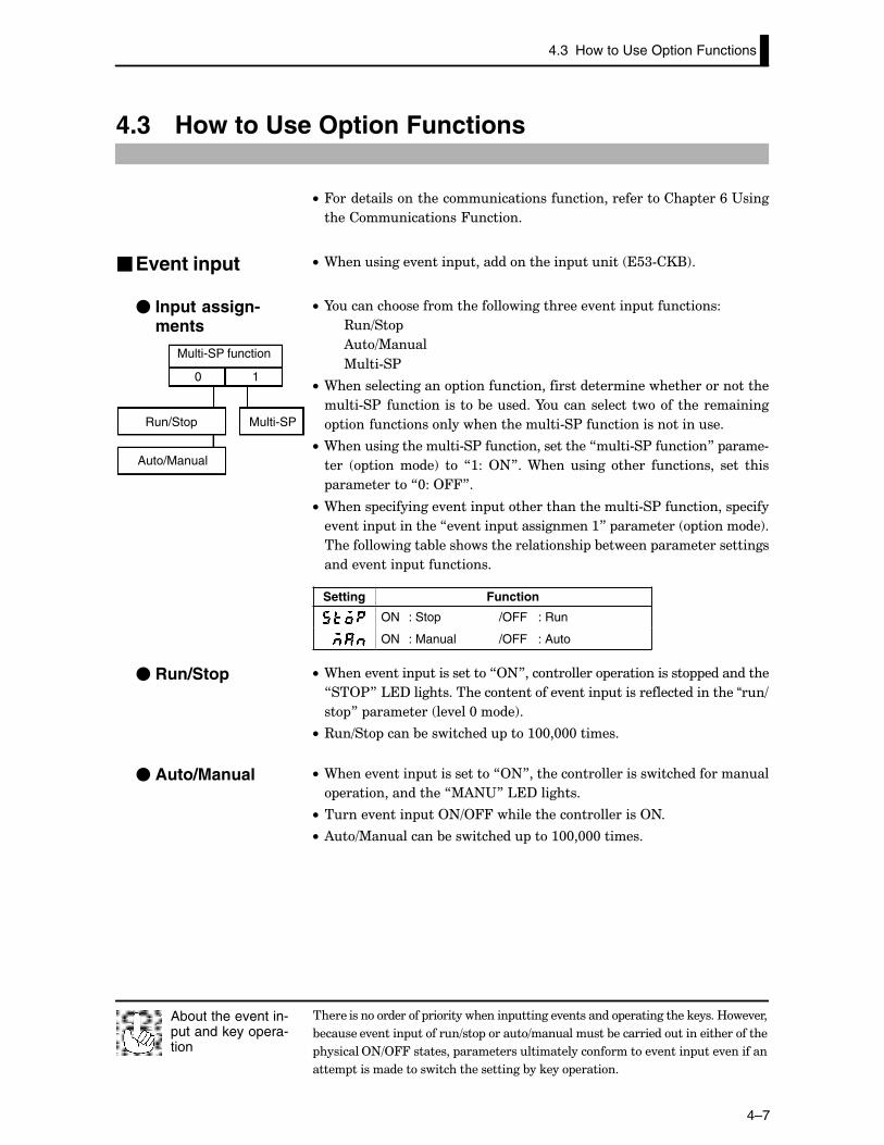
������������������ �������������� �������.��������� ������������������B��.���
&�������.������ ������=�� �����=����������&���������������������������
��������2+=244��������� �����������������������������.������ ���.��������
����� �������������������������������&������ �������
About the event in-put and key opera-tion
4.3 How to Use Option Functions
4–7
4.3 How to Use Option Functions
C• 4����������������������������������������������� ����/�"����
����������������4������
C• 9����������.������ ��������������� ������ ��<#��(!�
C• I���������������������������������.������ ����������
3�=��
)�=%����
%���#�$
C• 9����������������� ��������������������������������������������
����#�$�������������&�������I������������ ����� �������������
�����������������������������#�$��������������������
C• 9�����������������#�$�����������������7����#�$�������8� �����#
���� �������!� �� 7:�� 2+8��9���� ����� ����� ��������� ���� ����
�����������7@��2448�
C• 9����� ����������.������ ��������������������#�$���������� �����
�.������ ���������7�.������ ������������:8� ��������� �������!�
��������������&���������������������� �&������� �����������������
�����.������ ����������
Setting Function
ON : Stop /OFF : Run
ON : Manual /OFF : Auto
C• 9�����.������ �����������72+8����������� ������������ ����������
7��2$8�'�?�����������������������.������ ����������������������“��=
�� 8� ��������� ��.���@����!�
C• 3�=�� �����&����������� ���:@@�@@@�������
C• 9�����.������ �����������72+8�����������������������������������
����������������7%)+"8�'�?��������
C• �����.������ ��2+=244�����������������������2+�
C• )�=%���������&����������� ���:@@�@@@�������
�Event input
� Input assign-ments
0 1
Multi-SP function
Run/Stop
Auto/Manual
Multi-SP
� Run/Stop
� Auto/Manual
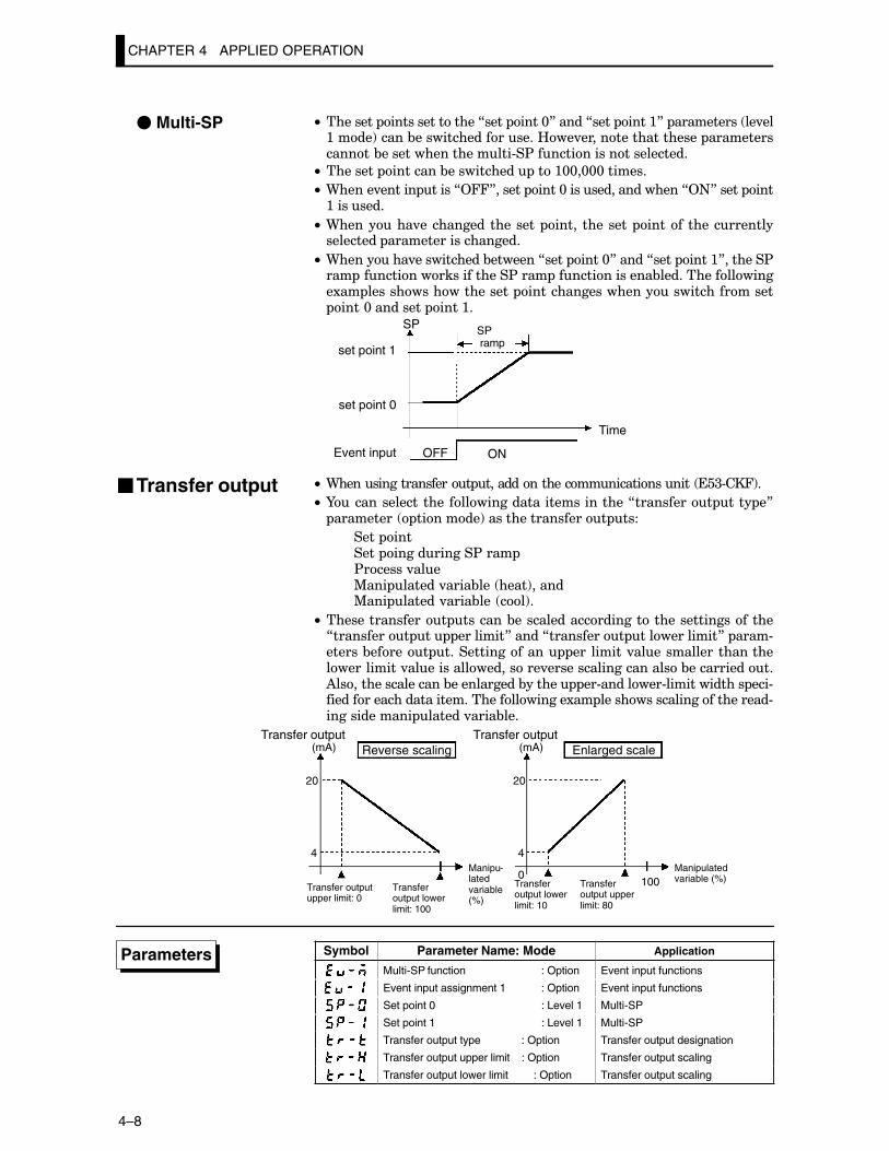
CHAPTER 4 APPLIED OPERATION
4–8
C• �������� ���������������7���� ����@8�����7���� ����:8� ���������� ��.��:����!�����&������������������B��.������������������� ���������������&�������������������#�$�����������������������
C• �������� ��������&����������� ���:@@�@@@�������
C• 9�����.������ �����72448������ ����@������������������72+8����� ���:��������
C• 9��������.������������������ ����� �������� ��������������������������� ��������������������
C• 9��������.�����������&�������7���� ����@8�����7���� ����:8�������$��� ���������������������$���� ��������������&�����������������1�� �������������������� ��������������������������������� ����@��������� ����:�
OFF ON
SP
set point 1
set point 0
Event input
Time
SP ramp
C• 9������������������� ����������������������������� ��<#��4!�
C• I������������������������������������������7���������� ���� �8 ��������� �������!������������������ ���
���� ������� �����������$���� $������.���%��� ������.����&��� ����!�����%��� ������.����&��� ��!�
C• ���������������� �������&��������������������������������������7���������� �� ��������8�����7���������� ������������8� ����#������&������ ���������������� ��� ������.�������������������������������.�������������������.���������������������&������������)������������������&�����������&������ ��#��������#������������� ���#�������������������������������������1�� ��������������������������#������������� ������.����&���
(mA)
20
4
20
4
0100
(mA)Transfer output Transfer output
Reverse scaling Enlarged scale
Transfer outputupper limit: 0
Transfer output lowerlimit: 100
Manipu-latedvariable(%)
Transfer output lowerlimit: 10
Transfer output upperlimit: 80
Manipulatedvariable (%)
Symbol Parameter Name: Mode Application
Multi-SP function : Option Event input functions
Event input assignment 1 : Option Event input functions
Set point 0 : Level 1 Multi-SP
Set point 1 : Level 1 Multi-SP
Transfer output type : Option Transfer output designation
Transfer output upper limit : Option Transfer output scaling
Transfer output lower limit : Option Transfer output scaling
� Multi-SP
�Transfer output
Parameters
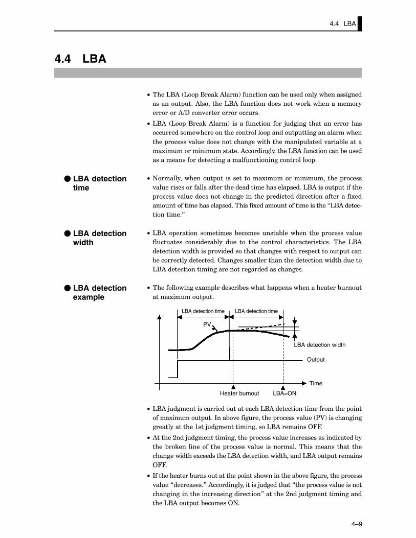
4.4 LBA
4–9
4.4 LBA
C• ����'()� ' �(�����)����!������������&�����������������������
������� ���)��������'()�������������������������������
�������)=?���.����������������
C• '()� ' �(�����)����!� ����� ������� ��� 5����������������������
����������������������������� ������ �������������������
���� ������.������������������������������� ������.����&�������
��1��������������������)���������������'()������������&�����
���������������������������������������������� �
C• +�������������� �� ��� ���� ����1�������������� ���� �����
.��������������������������������������������� �����'()����� ��������
������.������������������������� ����������������������������1��
������������������� ������������1����������������������7'()������#
���������8
C• '()� ������� ��������� &����������&�������� ���� ������.���
��������� ��������&��� ��� �� ���� ������ ����������������� ���� '()
������������������ �.���������������������������� ������� �����
&�����������������������������������������������������������������
'()��������������������������������������������
C• �������������1�� ���������&���������� ������������������&���
�����1����� ��
PV
LBA=ON
LBA detection time
LBA detection width
Output
Time
Heater burnout
LBA detection time
C• '()�5����������������������������'()����������������������� ���
����1����� ���*���&.������������� ������.���� $A!������������
���������������:���5�����������������'()���������244�
C• )������;���5������������������� ������.���������������������������&�
���� &����� ������� ���� ������.���� ��������������������� ����� ���
��������������1����������'()���������������������'()�� ���������
244�
C• *�������������&������������� �����������������&.������������� �����
.����7����������8�)�����������������5����������7���� ������.���������
�����������������������������������8��������;���5�����������������
����'()�� ��&������2+�
� LBA detectiontime
� LBA detectionwidth
� LBA detectionexample
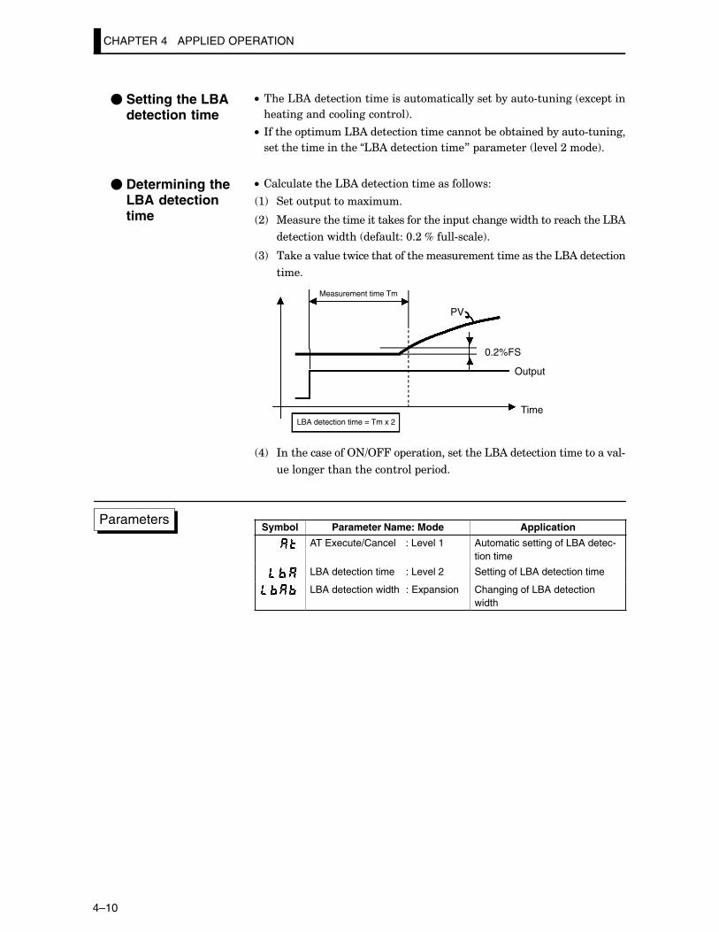
CHAPTER 4 APPLIED OPERATION
4–10
C• ����'()����������������������������������&����#������ �1�� ����
�����������������������!�
C• *������ �����'()���������������������&��&�������&����#������
��������������������“'()��������������8� ��������� ��.���;����!�
C• �������������'()������������������������
:! ����� ������1����
;! %��������������������������������� ���������������������������'()
��������������� ��������@�;�D����#�����!�
<! �������.��������������������������������������������'()���������
�����
PV
0.2%FS
Measurement time Tm
LBA detection time = Tm x 2
Output
Time
,! *�������������2+=244� ����������������'()�������������������.��#
����������������������� �����
Symbol Parameter Name: Mode Application
AT Execute/Cancel : Level 1 Automatic setting of LBA detec-tion time
LBA detection time : Level 2 Setting of LBA detection time
LBA detection width : Expansion Changing of LBA detectionwidth
� Setting the LBAdetection time
� Determining theLBA detectiontime
Parameters
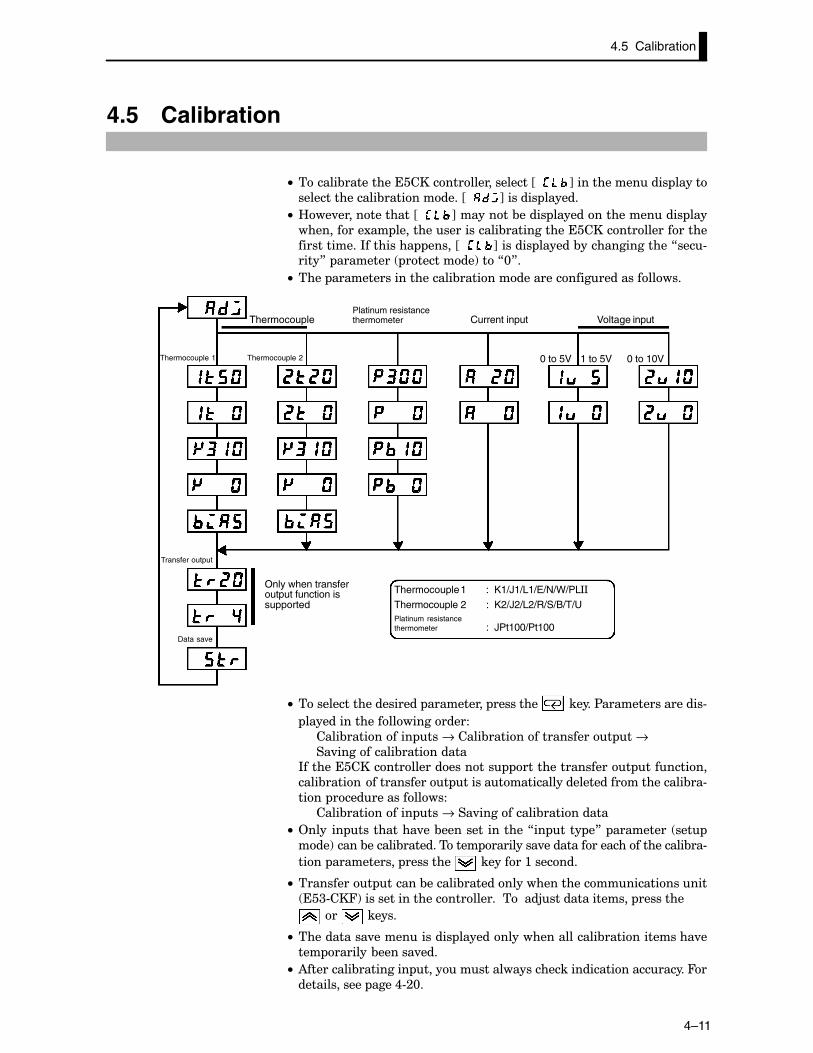
4.5 Calibration
4–11
4.5 Calibration
C• ������&�������������������������������JCC K��������������� �����
���������������&�����������JCC K������� ������
C• B��.�������������JCC K��������&����� ������������������� ���
����������1�� �������������������&�������������������������������
������������*��������� �����JCC K������� ������&���������������7���#����8� ��������� ���������!���7@8�
C• ���� ���������������������&��������������������������������
0 to 10V0 to 5V 1 to 5V
Thermocouple
Thermocouple 1
Transfer output
Data save
Platinum resistance thermometer Voltage inputCurrent input
Thermocouple 2
Thermocouple 1 : K1/J1/L1/E/N/W/PL**
Thermocouple 2 : K2/J2/L2/R/S/B/T/UPlatinum resistance thermometer : JPt100/Pt100
Only when transferoutput function issupported
C• ��������������������� ���������� ��������� ������$�����������������#
��������������������������
����&���������� ���→�����&������������������ ��→�
��.����������&����������*���������������������������� ����������������� ���������
����&������������������ �������������������������������������&��#
���� ����������������
����&���������� ���→���.����������&����������
C• 2������ ����������.��&���������������7�� ���� �8� ��������� ���
���!�����&������&������������ ���������.�������������������������&��#
���� ����������� ��������� ��������:�������
C• ���������� ������&������&����������������������������������
��<#��4!C��C���C��C���C���������M�M��5��C����C������C ����C���
��� ������
C• �����������.������������ �����������������������&��������������.�
��� �������&������.���
C• )���������&��������� �����������������������������������������4�
������������� ����,#;@�
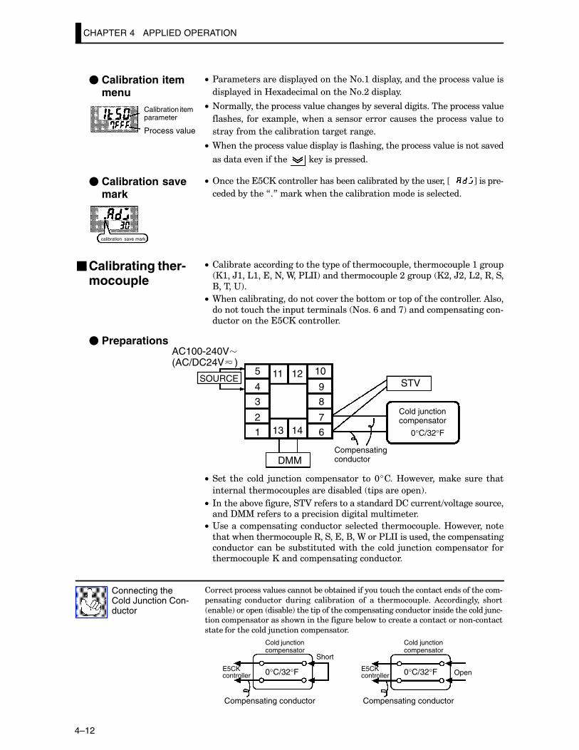
CHAPTER 4 APPLIED OPERATION
4–12
C• $����������������� ������������+�:���� ������������� ������.������
��� ���������B�1���������������+�;���� ����
C• +������������ ������.������������&����.����������������� ������.���
��������� ����1�� �������������������������������� ������.�����
������������������&�������������������
C• 9�������� ������.������� ��������������������� ������.������������.��
���������.���������� �������� �������
C• 2��������������������������&��������&������&�����������JCCC K���� ��#
������&������7�8�������������������&����������������������
C• ����&���������������������� ���������� ���������� ���:���
�:��H:��':�����+��9��$'**!����������� ���;��� � �;��H;��';��3����
(�����"!�
C• 9��������&��������������.�������&������� �����������������)���
��������������� ������������ +���/�����>!������� �����������#
�������������������������
� Preparations
5
4
3
2
1
10
9
8
7
613 14
11 12STV
DMM
0°C/32°F
Cold junctioncompensator
Compensatingconductor
SOURCE
AC100-240V(AC/DC24V )
C• ���� ���� ���� 5������ �� ������� �� @����B��.��������� ���� ����
��������������� ������������&���� �� ������ ��!�
C• *�������&.�����������A���������������������?��������=.���������������?%%������������ ��������������������������
C• "������� ������������������������������� ����B��.�������
���������������� ���3��������(��9���$'**��������������� ��������
�����������&���&��������������������� 5�������� ������� �������� ����������� ����������������
������� ������.�����������&��&����������������������������������������#
��������� ������� ������ ����&������ �� �� ������ ���� )����������� ����
���&��!��� ��� ����&��!������� ��������� �������������������������������5��#
������ ����������������������������&��������������������������#������
�����������������5�������� �������
Connecting theCold Junction Con-ductor
0°C/32°F 0°C/32°F
Cold junctioncompensator
Cold junctioncompensator
E5CKcontroller
E5CKcontroller
Compensating conductor Compensating conductor
Short
Open
� Calibration itemmenu
Calibration itemparameter
Process value
� Calibration savemark
calibration save mark
�Calibrating ther-mocouple
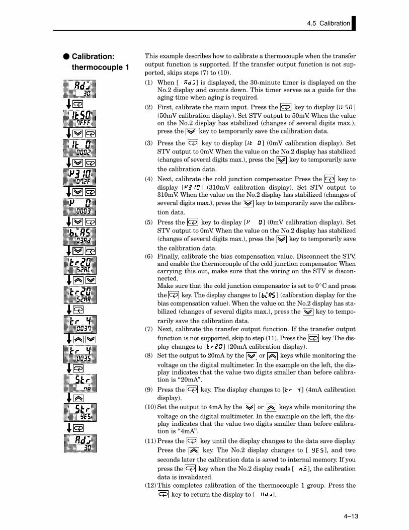
4–13
������1�� ���������&������������&������������� ��������������������
� ������������� ������*���������������� ���������������� #
��������� ����� �� >!��� :@!�
:! 9����JCCC K������� �����������<@#������������������ �����������+�;���� ��������������������������������.����������������������������������������������-�����
;! 4����������&���������������� ���$��������� ���������� ����J K
�@�A�����&��������� ���!��������A�� �����@�A��9��������.���������+�;���� �����������&���6��� ������������.��������������1�!�
��������� ���������� ���������.����������&�����������
<! $��������� ���������� ����J K� @�A�����&��������� ���!�����
��A�� ����@�A��9��������.����������+�;���� �����������&���6��
������������.��������������1�!�� ��������� ���������� ���������.�
��������&�����������
,! +�1�������&�������������5�������� ��������$��������� ������
��� ���� J K� <:@�A� ����&������ ��� ���!�� ���� ��A� � �� �<:@�A��9��������.����������+�;���� �����������&���6��� ���������
��.��������������1�!�� ��������� ���������� ���������.����������&��#
���������
�! $��������� ���������� ����J K� @�A�����&��������� ���!�����
��A�� ����@�A��9��������.����������+�;���� �����������&���6��
������������.��������������1�!�� ��������� ���������� ���������.�
��������&�����������
/! 4������������&���������&������ ��������.�����?���������������A��������&������������� �������������5�������� ��������9�����������������������������������������������������A���������#�������%���������������������5�������� ����������������@������� ����
���� ������������� ��������������J K� ����&��������� ����������
&������ ��������.���!��9��������.����������+�;���� �����������#
&���6��� ������������.��������������1�!�� ��������� ���������� #
���������.����������&�����������
>! +�1�������&������������������� ����������*���������������� �
�������������� ��������� ������ � ::!��$��������� �������������#
��������������J K� ;@�)�����&��������� ���!�
E! ��������� ����;@�)�&������ ��� ������������������������
.�������������������������������*�������1�� ����������������������# �����������������������.���������������������������&���������&��#�������7;@�)8�
G! $��������� ������������� ��������������J K� ,�)�����&�����
��� ���!�
:@! ��������� ����,�)�&������ ��� ������������������������
.�������������������������������*�������1�� ����������������������# �����������������������.���������������������������&���������&��#�������7,�)8�
::!$��������� ����������������� �������������������������.����� ����
$����� ���� � ����� ����+�;� ��� ���� �������� �� JCC K�� ���� ��
���������������������&����������������.���������������������*���
��������� ��������������+�;���� ����������JCCC K����������&�����
����������.���������
:;!������� ����������&�������� ���������� ���:��� ��$��������
�������������������� ������JCCC K�
� Calibration: thermocouple 1
4.5 Calibration
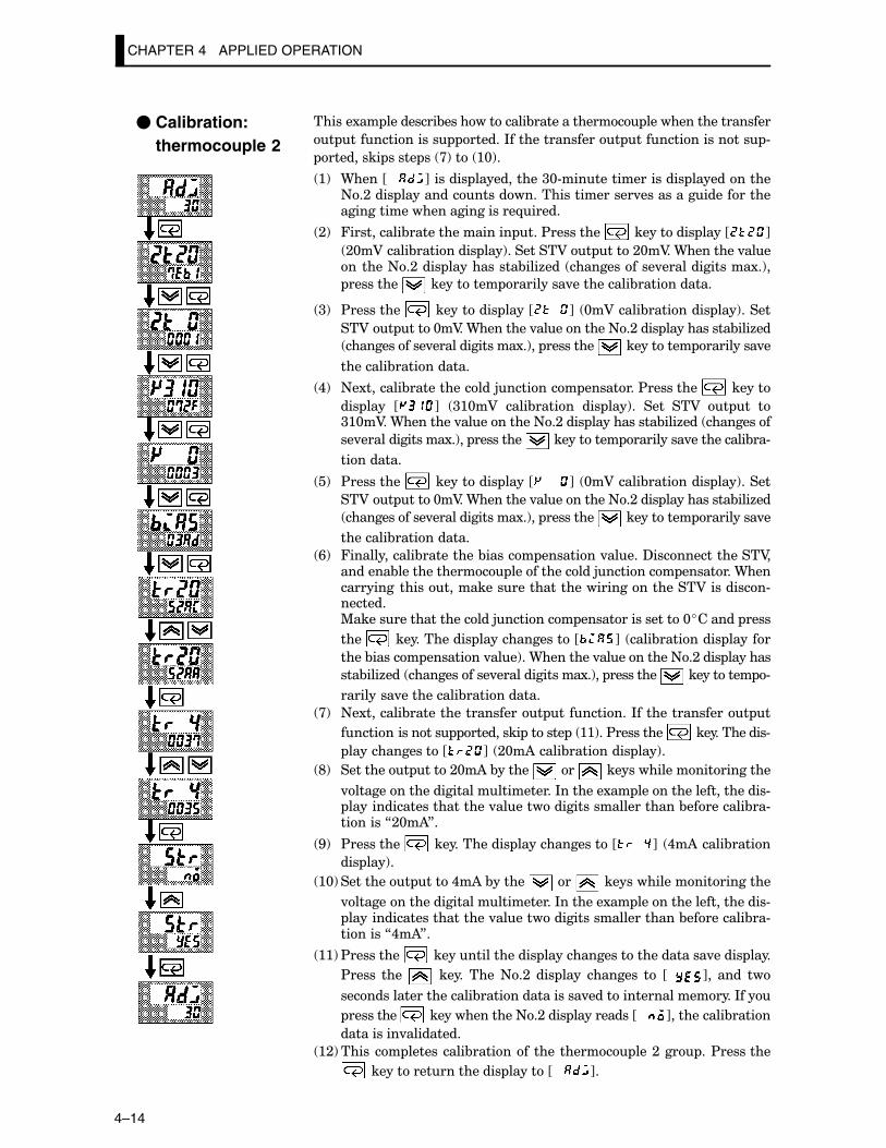
CHAPTER 4 APPLIED OPERATION
4–14
������1�� ���������&������������&������������� ��������������������
� ������������� ������*���������������� ���������������� #
��������� ����� �� >!��� :@!�
:! 9����JCCC K������� �����������<@#������������������ �����������+�;���� ��������������������������������.����������������������������������������������-�����
;! 4����������&���������������� ���$��������� ���������� ����J K
;@�A�����&��������� ���!��������A�� ����;@�A��9��������.���������+�;���� �����������&���6��� ������������.��������������1�!�
��������� ���������� ���������.����������&�����������
<! $��������� ���������� ����J K� @�A�����&��������� ���!�����
��A�� ����@�A��9��������.����������+�;���� �����������&���6��
������������.��������������1�!�� ��������� ���������� ���������.�
��������&�����������
,! +�1�������&�������������5�������� ��������$��������� ������
��� ���� J K� <:@�A� ����&������ ��� ���!�� ���� ��A� � �� �<:@�A��9��������.����������+�;���� �����������&���6��� ���������
��.��������������1�!�� ��������� ���������� ���������.����������&��#
���������
�! $��������� ���������� ����J K� @�A�����&��������� ���!�����
��A�� ����@�A��9��������.����������+�;���� �����������&���6��
������������.��������������1�!�� ��������� ���������� ���������.�
��������&�����������
/! 4������������&���������&������ ��������.�����?���������������A��������&������������� �������������5�������� ��������9�����������������������������������������������������A���������#�������%���������������������5�������� ����������������@������� ����
���� ������������� ��������������J K� ����&��������� ������
����&������ ��������.���!��9��������.����������+�;���� �������
���&���6��� ������������.��������������1�!�� ��������� ���������� #
���������.����������&�����������
>! +�1�������&������������������� ����������*���������������� �
�������������� ��������� ������ � ::!��$��������� �������������#
��������������J K� ;@�)�����&��������� ���!�
E! ��������� ����;@�)�&������ ��� ������������������������
.�������������������������������*�������1�� ����������������������# �����������������������.���������������������������&���������&��#�������7;@�)8�
G! $��������� ������������� ��������������J K� ,�)�����&�����
��� ���!�
:@! ��������� ����,�)�&������ ��� ������������������������
.�������������������������������*�������1�� ����������������������# �����������������������.���������������������������&���������&��#�������7,�)8�
::!$��������� ����������������� �������������������������.����� ����
$����� ���� � ����� ����+�;� ��� ���� �������� �� JCC K�� ���� ��
���������������������&����������������.���������������������*���
��������� ��������������+�;���� ����������JCCC K����������&�����
����������.���������
:;!������� ����������&�������� ���������� ���;��� ��$��������
�������������������� ������JCCC K�
� Calibration:thermocouple 2
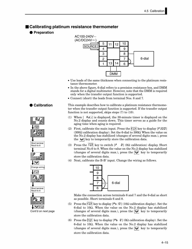
4–15
�Calibrating platinum resistance thermometer� Preparation
5
4
3
2
1
10
9
8
7
613 14
11 12
6-dial
DMM
SOURCE
AC100-240V(AC/DC24V )
C• "��������������������������������������������������� ������������#�����������������
C• *�������&.���������/#���������������� �������������������&1������?%%�������������������������������B��.�����������������?%%������-��������������������������� ������������� �����
C• ������� ����!������������������������+���/�����>�
������1�� ���������&������������&������� �������������������������#
����������������������� ������������� ������*���������������� �
�������������� ��������� ����� �� >!��� :@!�
:! 9����JCCC K������� �����������<@#������������������ �����������+�;���� ��������������������������������.����������������������������������������������-�����
;! 4����������&���������������� ���$��������� ���������� ����J K
<@@�����&��������� ���!����������/#�������<@@��9��������.���������+�;���� �����������&���6��� ������������.��������������1�!�� �������� ���������� ��������������������&�����������
<! $��������� ��������������J K� @� ����&�����!���� ���������
���������+�/���E��9��������.����������+�;���� �����������&���6��
������������.��������������1�!�� ��������� � ���� �� ��� ������
�������������&�����������
,! +�1�������&���������(#(0��� ������������������������������
10
9
8
7
6
6-dial
%���������������������������������/�����>���������/#������������
��� ���&�������������������/�����E�
�! $��������� ���������� ����J K� :@�����&��������� ���!���������
/#����� �� :@���9���� ���� .���� �� ����+�;� ��� ���� ���� ���&���6�� ������������.��������������1�!�� ��������� � ���� �� ��� ������
�������������&�����������
/! $��������� ���������� ����J K� @�����&��������� ���!���������
/#����� �� :@���9���� ���� .���� �� ����+�;� ��� ���� ���� ���&���6��
������������.��������������1�!�� ��������� � ���� �� ��� ������
�������������&�����������
� Calibration
Cont’d on next page
Change wiring.
Short terminalNos.6 to 8
Short terminalNos.6 to 8
4.5 Calibration
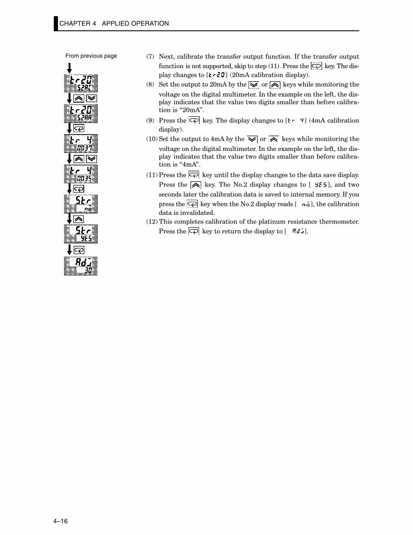
CHAPTER 4 APPLIED OPERATION
4–16
>! +�1�������&������������������� ����������*���������������� �
�������������� ��������� ������ � ::!��$��������� �������������#
��������������J K� ;@�)�����&��������� ���!�
E! ��������� ����;@�)�&������ ��� ������������������������
.�������������������������������*�������1�� ����������������������#
�����������������������.���������������������������&���������&��#
�������7;@�)8�
G! $��������� ������������� ��������������J K� ,�)�����&�����
��� ���!�
:@! ��������� ����,�)�&������ ��� ������������������������
.�������������������������������*�������1�� ����������������������#
�����������������������.���������������������������&���������&��#
�������7,�)8�
::!$��������� ����������������� �������������������������.����� ����
$����� ���� � ����� ����+�;� ��� ���� �������� �� JCC K�� ���� ��
���������������������&����������������.���������������������*���
��������� ��������������+�;���� ����������JCCC K����������&�����
����������.���������
:;!������� ����������&������������ �����������������������������
$��������� �������������������� ������JCCC K�
From previous page
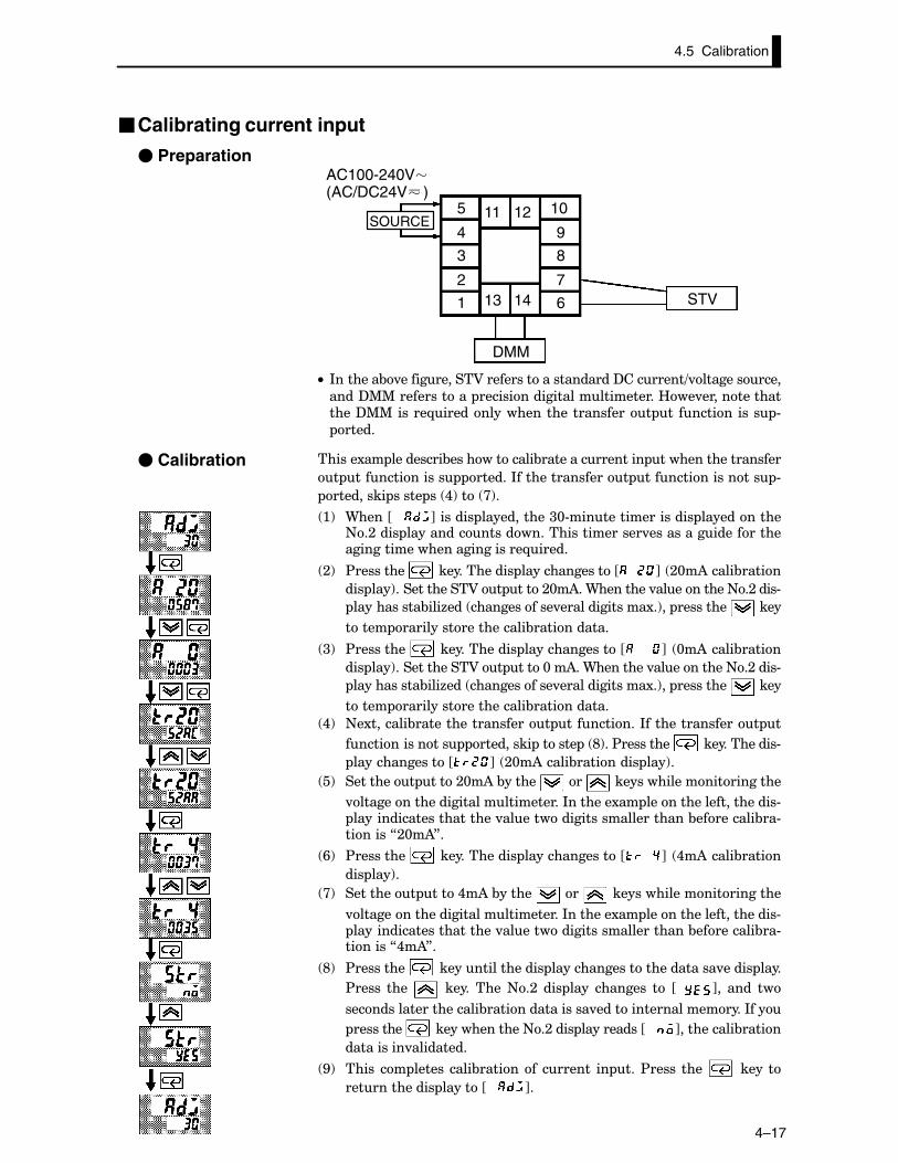
4–17
�Calibrating current input
� Preparation
5
4
3
2
1
10
9
8
7
613 14
11 12
STV
DMM
SOURCE
AC100-240V(AC/DC24V )
C• *�������&.�����������A���������������������?��������=.�����������
����?%%������������ ���������������������������B��.����������������?%%������-���������������������������� �� ������� ���� #
�����
������1�� ���������&������������&���������������� �������������������
� ������������� ������*���������������� ���������������� #
��������� ����� �� ,!��� >!�
:! 9����JCCC K������� �����������<@#������������������ �����������+�;���� ��������������������������������.����������������������������������������������-�����
;! $��������� ������������� ��������������J K� ;@�)�����&�����
��� ���!������������A�� ����;@�)��9��������.����������+�;����#
�����������&���6��� ������������.��������������1�!�� ��������� ����
����� ��������������������&�����������
<! $��������� ������������� ��������������J K� @�)�����&�����
��� ���!������������A�� ����@��)��9��������.����������+�;����#
�����������&���6��� ������������.��������������1�!�� ��������� ����
����� ��������������������&�����������
,! +�1�������&������������������� ����������*���������������� �
�������������� ��������� ������ � E!��$��������� �������������#
��������������J K� ;@�)�����&��������� ���!�
�! ��������� ����;@�)�&������ ��� ������������������������
.�������������������������������*�������1�� ����������������������# �����������������������.���������������������������&���������&��#�������7;@�)8�
/! $��������� ������������� ��������������J K� ,�)�����&�����
��� ���!�
>! ��������� ����,�)�&������ ��� ������������������������
.�������������������������������*�������1�� ����������������������# �����������������������.���������������������������&���������&��#�������7,�)8�
E! $��������� ����������������� �������������������������.����� ����
$����� ���� � ����� ����+�;� ��� ���� �������� �� JCC K�� ���� ��
���������������������&����������������.���������������������*���
��������� ��������������+�;���� ����������JCCC K����������&�����
����������.���������
G! ����� �� ������ ����&�������� ������� �� ���$����� ���� ������
������������� ������JCCC K�
� Calibration
4.5 Calibration
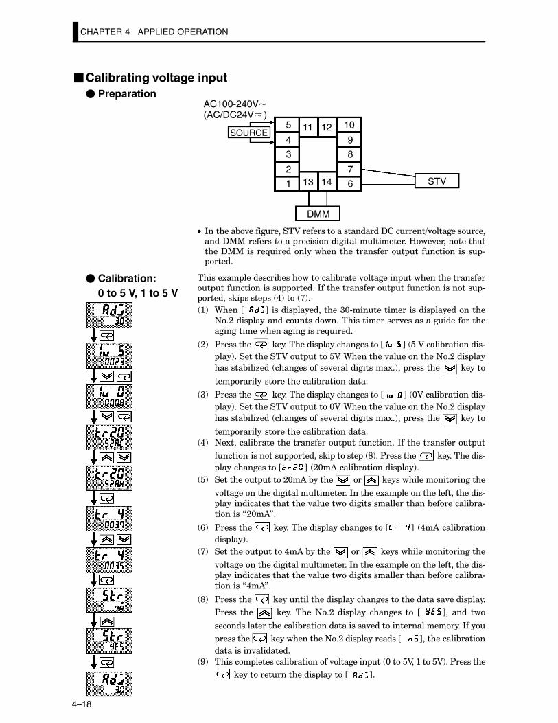
CHAPTER 4 APPLIED OPERATION
4–18
�Calibrating voltage input� Preparation
5
4
3
2
1
10
9
8
7
613 14
11 12
STV
DMM
SOURCE
AC100-240V(AC/DC24V )
C• *�������&.�����������A���������������������?��������=.���������������?%%������������ ���������������������������B��.����������������?%%������-���������������������������� �� ������� ���� # �����
������1�� ���������&������������&�����.�������� �������������������� ������������� ������*���������������� ���������������� # ��������� ����� �� ,!��� >!�
:! 9����JCC K������� �����������<@#������������������ �����������
+�;���� ��������������������������������.����������������������������������������������-�����
;! $��������� ������������� ��������������J K� ��A�����&���������#
���!������������A�� �����A��9��������.����������+�;���� ���
�������&���6��� ������������.��������������1�!�� ��������� ������
��� ��������������������&�����������
<! $��������� ������������� ��������������J K� @A�����&���������#
���!������������A�� ����@A��9��������.����������+�;���� ���
�������&���6��� ������������.��������������1�!�� ��������� ������
��� ��������������������&�����������
,! +�1�������&������������������� ����������*���������������� �
�������������� ��������� ������ � E!��$��������� �������������#
��������������J K� ;@�)�����&��������� ���!�
�! ��������� ����;@�)�&������ ��� ������������������������
.�������������������������������*�������1�� ����������������������#
�����������������������.���������������������������&���������&��#
�������7;@�)8�
/! $��������� ������������� ��������������J K� ,�)�����&�����
��� ���!�
>! ��������� ����,�)�&������ ��� ������������������������
.�������������������������������*�������1�� ����������������������#
�����������������������.���������������������������&���������&��#
�������7,�)8�
E! $��������� ����������������� �������������������������.����� ����
$����� ���� � ����� ����+�;� ��� ���� �������� �� JCC K�� ���� ��
���������������������&����������������.���������������������*���
��������� ��������������+�;���� ����������JCCC K����������&�����
����������.���������
G! ������� ����������&��������.�������� �� @����A��:����A!��$��������
�������������������� ������JCC K�
� Calibration: 0 to 5 V, 1 to 5 V
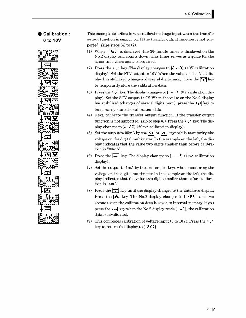
4–19
������1�� ���������&������������&�����.�������� �������������������
� ������������� ������*���������������� ���������������� #
��������� ����� �� ,!��� >!�
:! 9����JCC K������� �����������<@#������������������ �����������
+�;���� ��������������������������������.�������������������
���������������������������-�����
;! $��������� ������������� ��������������J K� :@A�����&�����
��� ���!������������A�� ����:@A��9��������.����������+�;����#
�����������&���6��� ������������.��������������1�!�� ��������� ����
����� ��������������������&�����������
<! $��������� ������������� ��������������J K� @A�����&���������#
���!������������A�� ����@A��9��������.����������+�;���� ���
�������&���6��� ������������.��������������1�!�� ��������� ������
��� ��������������������&�����������
,! +�1�������&������������������� ����������*���������������� �
�������������� ��������� ������ � E!��$��������� �������������#
��������������J K� ;@�)�����&��������� ���!�
�! ��������� ����;@�)�&������ ��� ������������������������
.�������������������������������*�������1�� ����������������������#
�����������������������.���������������������������&���������&��#
�������7;@�)8�
/! $��������� ������������� ��������������J K� ,�)�����&�����
��� ���!�
>! ��������� ����,�)�&������ ��� ������������������������
.�������������������������������*�������1�� ����������������������#
�����������������������.���������������������������&���������&��#
�������7,�)8�
E! $��������� ����������������� �������������������������.����� ����
$����� ���� � ����� ����+�;� ��� ���� �������� �� JCC K�� ���� ��
���������������������&����������������.���������������������*���
��������� ��������������+�;���� ����������JCCC K����������&�����
����������.���������
G! ������� ����������&��������.�������� �� @���:@A!��$���������
������������������� ������JCC K�
� Calibration : 0 to 10V
4.5 Calibration
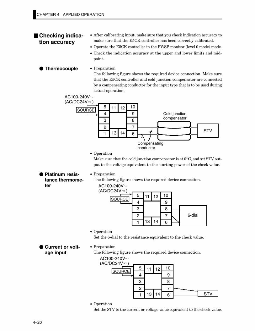
CHAPTER 4 APPLIED OPERATION
4–20
C• )���������&��������� ��������������������������������������������
������������������������������������&�����������������&������
C• 2 �������������������������������$A=�$������� ��.���@����!�����
C• ����������������������������������� ��������������������������#
����
C• $�� ������
�����������������������������-�������.��������������%�������
�������������������������������5�������� �������������������
&������ ������������������������� ���� ������������&�����������
������ �������
5
4
3
2
1
10
9
8
7
613 14
11 12
STV
Cold junctioncompensator
Compensatingconductor
SOURCE
AC100-240V(AC/DC24V )
C• 2 ������
%���������������������5�������� �������������@��������������A��#
��������.�������-�.��������������������� ����������������.����
C• $�� ������
�����������������������������-�������.�������������
5
4
3
2
1
10
9
8
7
613 14
11 12
6-dial
SOURCE
AC100-240V(AC/DC24V )
C• 2 ������
��������/#�����������������������-�.������������������.����
C• $�� ������
�����������������������������-�������.�������������
5
4
3
2
1
10
9
8
7
613 14
11 12
STV
SOURCE
AC100-240V(AC/DC24V )
C• 2 ������
����������A����������������.������.�����-�.������������������.����
�Checking indica-tion accuracy
� Thermocouple
� Platinum resis-tance thermome-ter
� Current or volt-age input
CHAPTER 5 PARAMETERS
5–1
CHAPTER 5PARAMETERS
�������� ����������&������� ����������������������"����������� ������
�����������������
CHAPTER5
��.�������"��������������� ��� �#;������������������������
$������%�� �#<��������������������������������������������������������������
%�����%�� �#�������������������������������������������������������������
'�.���@�%�� �#/��������������������������������������������������������������
'�.���:�%�� �#G��������������������������������������������������������������
'�.���;�%�� �#:���������������������������������������������������������������
��� �%�� �#;:����������������������������������������������������������������
�1 ������%�� �#;>��������������������������������������������������������
2 ����%�� �#<;��������������������������������������������������������������
����&������%�� �#</������������������������������������������������������
CHAPTER 5 PARAMETERS
5–2
�The meaning of icons used in this chapter
?�����&��������������������� ���������
?�����&������������������������������� �����������������
"������������#���������� ����������
?�����&�������������������������.�����
?�����&����� ������������ ������������� �������������������
?�����&����������� ��������������������
?�����&��� ������ �� ���� ����� �� ���� ����� � ������ ���� ��������� &����
������&���
�About parameter display2������������������������� �������������������&������������� ������������� �������������
��� �������������������7�����������"��8������������������� �������������������������������
B��.���������������������������� �������� ��������������������.�������������������� �����
�������������������������������
Conditions of UseThe controller must be in operation.
AT Execute/cancel
Conventions Used in this Chapter
Function
Comment
Monitor
Example of use
See
Model
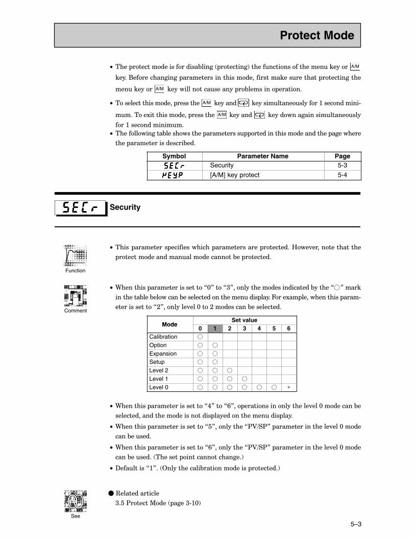
5–3
C• ���� ��������������������&����� ��������!����������������������������� A/M
�����(�������������� ������������������������������������������� ������������
���������� A/M ���������������������� �&�������� �������
C• ������������������� ��������� A/M ��������� ��������������������:�����������#
�������1������������� ��������� A/M ��������� ��������������������������
���:��������������
C• ��������������&������������ ����������� ������������������������� ���������
���� ������������������&���
Symbol Parameter Name PageSecurity 5-3
[A/M] key protect 5-4
Security
C• ����� ���������� �������������� �������������� ���������B��.����������������
������������������������������&�� ��������
C• 9��������� ������������������7@8���7<8�������������������������&������7�8�����
���������&���&��������&������������������������ �����4���1�� �������������� ����#
��������������7;8��������.���@���;����������&�����������
ModeSet value
Mode0 1 2 3 4 5 6
Calibration �
Option � �
Expansion � �
Setup � �
Level 2 � � �
Level 1 � � � �
Level 0 � � � � � � ∗
C• 9��������� ������������������7,8���7/8�� ���������������������.���@���������&�
������������������������������� ������������������� ����
C• 9��������� ������������������7�8����������7$A=�$8� ������������������.���@����
����&������
C• 9��������� ������������������7/8����������7$A=�$8� ������������������.���@����
����&������� �������� �����������������!
C• ?���������7:8�� 2������������&������������� ��������!
�C3��������������
<���$������%��� ����<#:@!
Protect Mode
Function
Comment
See
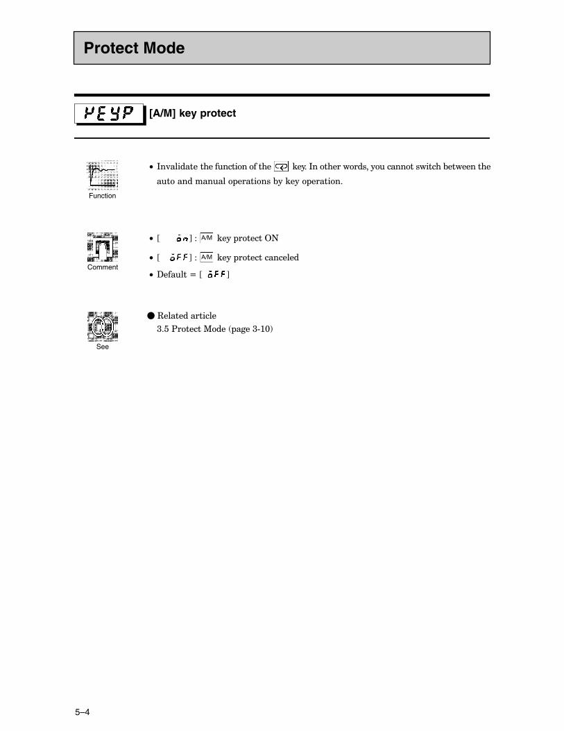
CHAPTER 5 PARAMETERS
5–4
[A/M] key protect
C• *�.������������������������� ������*����������������������������&����������
������������� ��������&������ �������
C• JC CCC K �� A/M ����� ������2+
C• J K �� A/M ����� ��������������
C• ?������N�J K
�C3��������������
<���$������%��� ����<#:@!
Protect Mode
Function
Comment
See
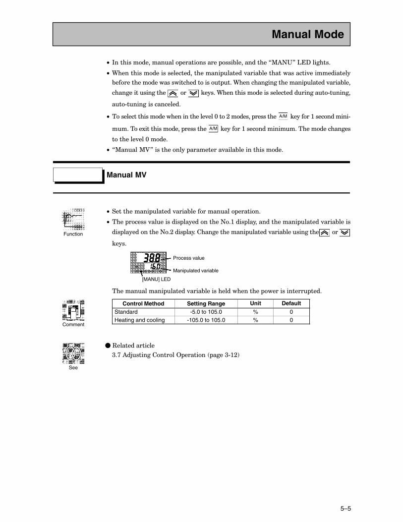
5–5
C• *������������������ ������������ ���&������������7%)+"8�'�?��������
C• 9���������������������������������� ������.����&����������������.�������������
&�������������������������������� ���9��������������������� ������.����&���
������������������� ��� �������9���������������������������������#������
��#������������������
C• ��������������������������������.���@���;������� ��������� A/M ��������:�����������#
�������1������������� ��������� A/M ��������:������������������������������
��������.���@�����
C• 7%�����%A8������������ ����������.����&���������������
Manual MV
C• ������������ ������.����&������������ �������
C• ���� ������.���������� ������������+�:���� ����������������� ������.����&�����
��� ������������+�;���� �������������������� ������.����&����������� ���
�����
Process value
Manipulated variable
[MANU] LED
�������������� ������.����&�������������������� ������������� ����
Control Method Setting Range Unit Default
Standard -5.0 to 105.0 % 0Heating and cooling -105.0 to 105.0 % 0
�C3��������������
<�>�)�5������������2 ������� ����<#:;!
Manual Mode
Function
Comment
See
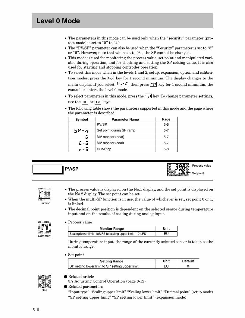
CHAPTER 5 PARAMETERS
5–6
C• ���� ��������������������������&�������������������7�������8� ��������� �#
��������!����������7@8���7,8�
C• ����7$A=�$8� �����������������&���������������7�������8� ������������������7�8
��7/8��B��.������������������������7/8�������$�������&����������
C• �������������������������������� ������.��������� ������������ ������.���#
�&��������� �����������������������������������������$���������.�����*��������
���������������������� ������������� �������
C• ��������������������������������.����:�����;����� ���1 ������� ������������&��#
���������� ��������� ��������:���������������������� �����������������
������� �����*�����������J K������ ����� ��������:������������������
����������������������.���@�����
C• ��������� ����������������������� ��������� ��������������� ������������������
������� ��� ������
C• ��������������&������������ ����������� ������������������������� ���������
���� ������������������&���
Symbol Parameter Name Page
PV/SP 5-6
Set point during SP ramp 5-7
MV monitor (heat) 5-7
MV monitor (cool) 5-7
Run/Stop 5-8
PV/SP
C• ���� ������.���������� ������������+�:���� ����������������� ���������� �������
����+�;���� ������������� ��������&������
C• 9������������#�$����������������������.������������.��������������� ����@���:�
����������
C• ������������ ���� ����������� ������������������������������������� ������
�� ������������������������������������������� ��
C• $������.���
Monitor Range UnitScaling lower limit -10%FS to scaling upper limit +10%FS EU
?�������� ��������� ����������������������������������������������������������
������������
C• ���� ���
Setting Range Unit Default
SP setting lower limit to SP setting upper limit EU 0
�C3��������������<�>�)�5������������2 ������� ����<#:;!
�C3������� ���������
7*� ���� �8�7�������� ��������8�7������������������8�7?������� ���8� ��� ����!
7�$��������� ��������8�7�$�������������������8� �1 ���������!
Level 0 Mode
Process value
Set point
Function
Comment
See
5–7
Set point during SP ramp Conditions of UseThe SP ramp function must be enabled.
C• ������������� ����
Moniter Range Unit DefaultSP setting lower limit to SP setting upper limit EU 0
�C3��������������
<�>�)�5������������2 ������� ����<F:;!
�C3������� ���������
7$A=�$8� ��.���@����!
7�$���� ���������8�7�$���� �����.���8� ��.���;����!
7���� ���� ��������8�7���� ��������������� �1 ���������!
MV monitor (heat)
MV monitor (cool)
C• ����� ���������������&������
C• %�������������� ������.����&������������������������������
C• �������� ������.����&������������������������������������������������7%A����#
��� ����!8� ���������
C• ����7%A������� ��!8� �������������&������������������������������������#
����
C• %A������� ����!
Control Monitor Range Unit
Standard -5.0 to 105.0 %Heating and cooling 0.0 to 105.0 %
C• %A������� ��!
Control Monitor Range Unit
Heating and cooling 0.0 to 105.0 %
Level 0 Mode
Function
Monitor
See
Function
Monitor
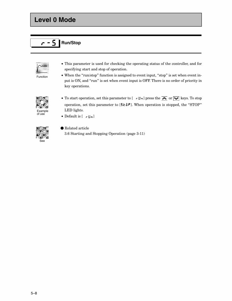
CHAPTER 5 PARAMETERS
5–8
Run/Stop
C• ����� �������������������������������� ������������������������������������
� ��������������������� ��� �������
C• 9��������7��=�� 8�����������������������.������ ���7�� 8��������������.������#
�����2+������7��8��������������.������ �����244�������������������� ���������
���� ��������
C• �������� ����������������� �����������JCCC K� ��������� ��� �����������
����������������� �����������J K��9���� ������������ ��������7��2$8
'�?��������
C• ?���������JCCC K�
�C3��������������
<�/���������������� ����2 ������� ����<#::!
Level 0 Mode
Function
Example of use
See
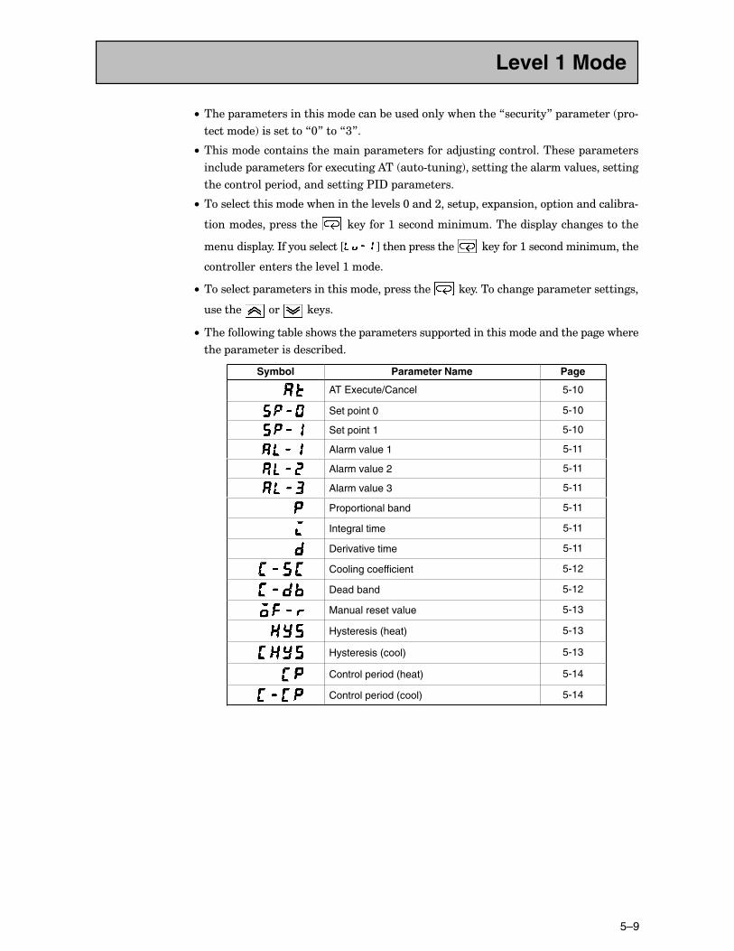
5–9
C• ���� ��������������������������&�������������������7�������8� ��������� �#
��������!����������7@8���7<8�
C• �������������������������� ���������������5������������������� ���������
������� ��������������1�������)�� ��#�����!��������������������.�������������
���������� ������������������$*?� ����������
C• ��������������������������������.����@�����;����� ���1 ������� ������������&��#
���������� ��������� ��������:���������������������� �����������������
������� �����*�����������J K������ ��������� ��������:������������������
����������������������.���:�����
C• ��������� ����������������������� ��������� ��������������� ������������������
������� ��� ������
C• ��������������&������������ ����������� ������������������������� ���������
���� ������������������&���
Symbol Parameter Name Page
AT Execute/Cancel 5-10
Set point 0 5-10
Set point 1 5-10
Alarm value 1 5-11
Alarm value 2 5-11
Alarm value 3 5-11
Proportional band 5-11
Integral time 5-11
Derivative time 5-11
Cooling coefficient 5-12
Dead band 5-12
Manual reset value 5-13
Hysteresis (heat) 5-13
Hysteresis (cool) 5-13
Control period (heat) 5-14
Control period (cool) 5-14
Level 1 Mode
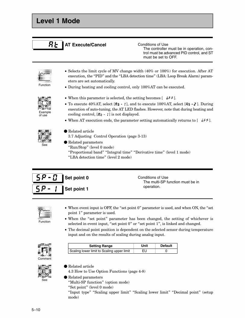
CHAPTER 5 PARAMETERS
5–10
AT Execute/Cancel Conditions of UseThe controller must be in operation, con-trol must be advanced PID control, and STmust be set to OFF.
C• ��������������������������%A�������������� ,@D���:@@D!�����1�������)�����)�
�1�����������7$*?8���������7'()��������������8� '()��' �(�����)����!� ����#
��������������������������
C• ?����������������������������������:@@D)������&���1������
C• 9��������� ����������������������������������&������JCCC K�
C• ���1�����,@D)����������J K���������1�����:@@D)����������J K��?����
�1����������#�����������)��'�?����������B��.������������������������������
�������������J K���������� ������
C• 9����)���1���������������� ��������������������������������������JCCC K�
�C3��������������
<�>�)�5�������������2 ������� ����<#:<!
�C3������� ���������
73�=�� 8� ��.���@����!
7$� �������&���8�7*������������8�7?���.���.������8� ��.���:����!
7'()��������������8� ��.���;����!
Set point 0
Set point 1
Conditions of UseThe multi-SP function must be in operation.
C• 9�����.������ �����244������7���� ����@8� ��������������������������2+������7���
����:8� ����������������
C• 9���� ���� 7���� ���8� ��������� ���� &���� ��������� ���� �������� �� ������.��� ��
�������������.������ ���7���� ����@8���7���� ����:8������������������������
C• ������������ ���� ����������� ������������������������������������� ������
�� ������������������������������������������� ��
Setting Range Unit Default
Scaling lower limit to Scaling upper limit EU 0
�C3��������������
,�<�B����"���2 ����4������� ����,#E!
�C3������� ���������
7%���#�$�������8� �������!
7���� ���8� ��.���@����!
7*� �� �� �8� 7�������� ��� �����8�7�������� ����� �����8�7?������� ���8� ���
���!
Level 1 Mode
Function
Example of use
See
Function
Comment
See
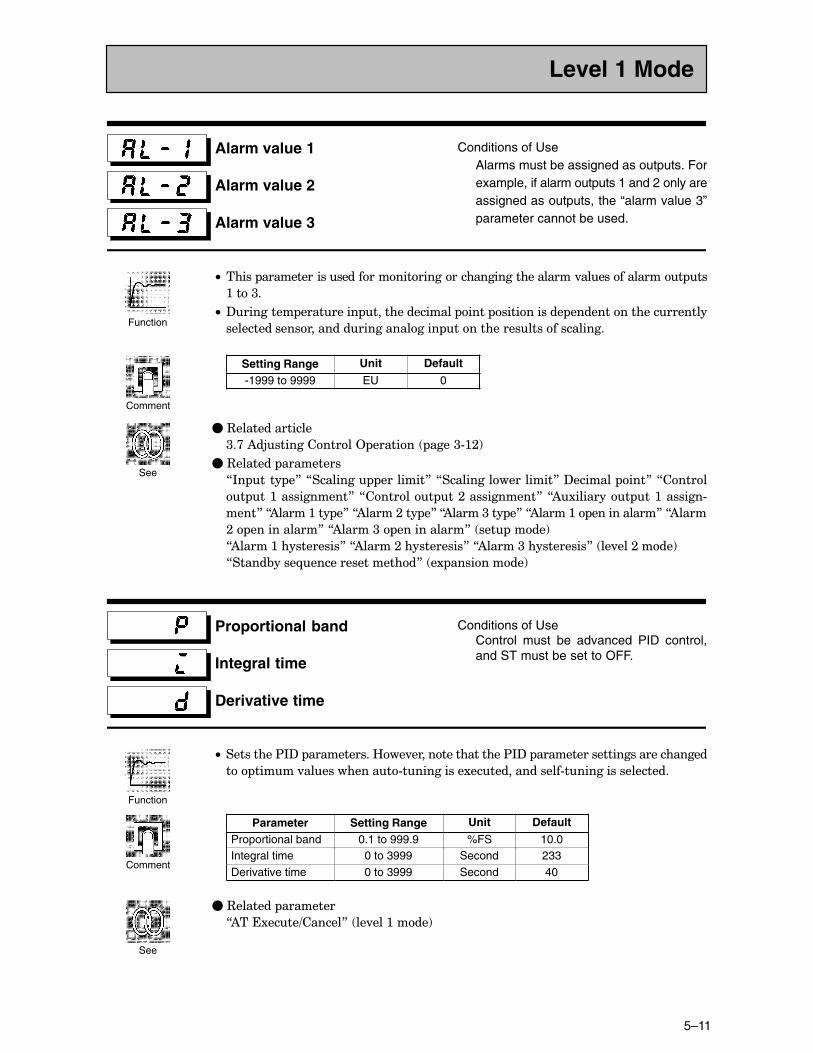
5–11
Alarm value 1
Alarm value 2
Alarm value 3
Conditions of UseAlarms must be assigned as outputs. Forexample, if alarm outputs 1 and 2 only areassigned as outputs, the “alarm value 3”parameter cannot be used.
C• ����� �������������������������������������������������.�������������� ��
:���<�
C• ?�������� ��������� ��������������� ���� ����������� ���������������������
���������������������������������� �������������������������
Setting Range Unit Default
-1999 to 9999 EU 0
�C3��������������
<�>�)�5������������2 ������� ����<#:;!
�C3������� ���������
7*� ���� �8�7�������� ��������8�7������������������8�?������� ���8�7�����
� ��:�����������8�7������� ��;�����������8�7)1�������� ��:�������#
����8�7)�����:��� �8�7)�����;��� �8�7)�����<��� �8�7)�����:� �����������8�7)����
;� �����������8�7)�����<� �����������8� ��� ����!
7)�����:�����������8�7)�����;�����������8�7)�����<�����������8� ��.���;����!
7�����&����-����������������8� �1 ���������!
Proportional band
Integral time
Derivative time
Conditions of UseControl must be advanced PID control,and ST must be set to OFF.
C• ���������$*?� �����������B��.�����������������$*?� �����������������������������
�� �����.������������#����������1���������������#������������������
Parameter Setting Range Unit Default
Proportional band 0.1 to 999.9 %FS 10.0Integral time 0 to 3999 Second 233Derivative time 0 to 3999 Second 40
�C3������� ��������
7)���1����=������8� ��.���:����!
Level 1 Mode
Function
Comment
See
Function
Comment
See
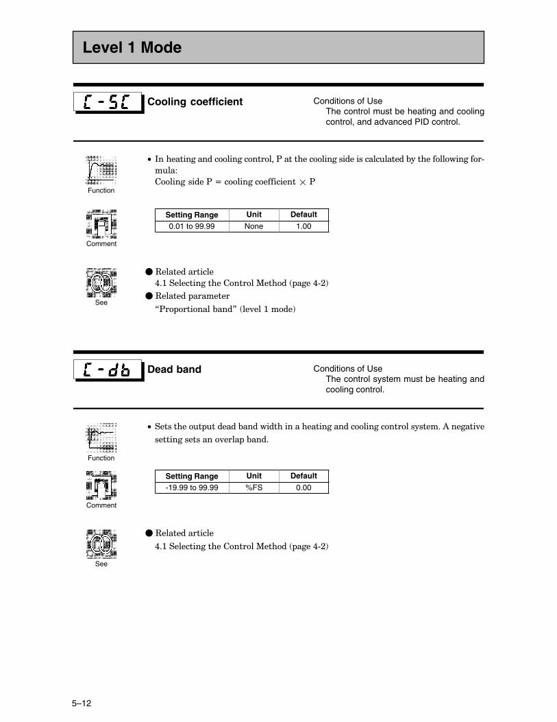
CHAPTER 5 PARAMETERS
5–12
Cooling coefficient Conditions of UseThe control must be heating and coolingcontrol, and advanced PID control.
C• *���������������������������$��������������������������������&����������������#
����
�����������$�N��������������������$
Setting Range Unit Default
0.01 to 99.99 None 1.00
�C3��������������
,�:���������������������%����� ����,#;!
�C3������� ��������
7$� �������&���8� ��.���:����!
Dead band Conditions of UseThe control system must be heating andcooling control.
C• ���������� �������&�����������������������������������������������)�������.�
����������������.���� �&����
Setting Range Unit Default
-19.99 to 99.99 %FS 0.00
�C3��������������
,�:���������������������%����� ����,#;!
Level 1 Mode
Function
Comment
See
Function
Comment
See
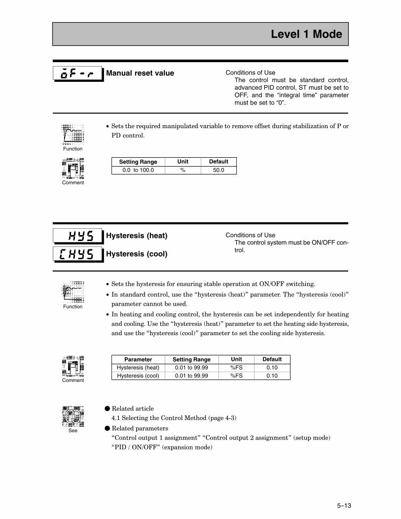
5–13
Manual reset value Conditions of UseThe control must be standard control,advanced PID control, ST must be set toOFF, and the “integral time” parametermust be set to “0”.
C• �����������-��������� ������.����&��������.�����������������&���6�������$��
$?�������
Setting Range Unit Default
0.0 to 100.0 % 50.0
Hysteresis (heat)
Hysteresis (cool)
Conditions of UseThe control system must be ON/OFF con-trol.
C• ����������������������������������&��� ����������2+=244�����������
C• *�������������������������7����������� ����!8� ��������������7����������� ��!8
���������������&������
C• *����������������������������������������������&���������� �������������������
�����������"�������7����������� ����!8� �������������������������������������������
�����������7����������� ��!8� �����������������������������������������
Parameter Setting Range Unit DefaultHysteresis (heat) 0.01 to 99.99 %FS 0.10Hysteresis (cool) 0.01 to 99.99 %FS 0.10
�C3��������������
,�:���������������������%����� ����,#<!
�C3������� ���������
7������� ��:�����������8�7������� ��;�����������8� ��� ����!
7$*?�=�2+=2448� �1 ���������!
Level 1 Mode
Function
Comment
Function
Comment
See
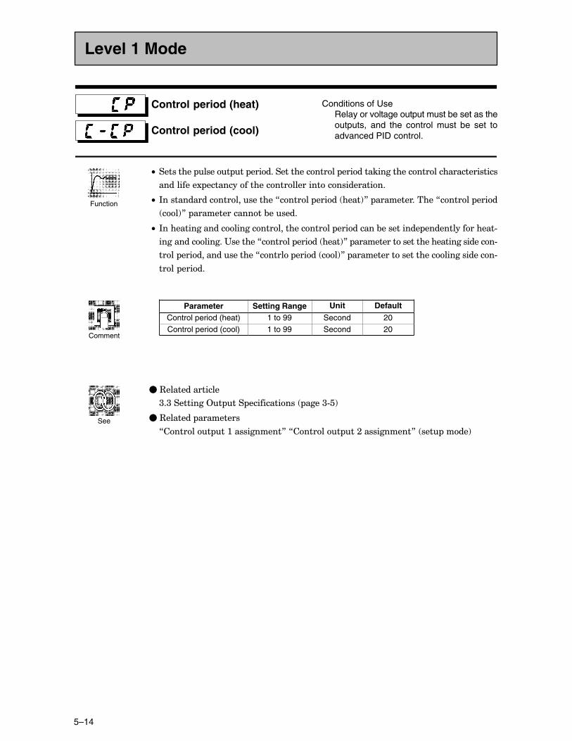
CHAPTER 5 PARAMETERS
5–14
Control period (heat)
Control period (cool)
Conditions of UseRelay or voltage output must be set as theoutputs, and the control must be set toadvanced PID control.
C• ��������� ����� �� �������������������� �������������������������������������
����������1 ���������������������������������������
C• *�������������������������7������ ����� ����!8� ��������������7������ ����
��!8� ���������������&������
C• *������������������������������������� ���������&���������� ����������������#
���������������"�������7������ ����� ����!8� ����������������������������������#
���� �����������������7������ ����� ��!8� ��������������������������������#
���� �����
Parameter Setting Range Unit Default
Control period (heat) 1 to 99 Second 20Control period (cool) 1 to 99 Second 20
�C3��������������
<�<���������2� ��� ������������ ����<#�!
�C3������� ���������
7������� ��:�����������8�7������� ��;�����������8� ��� ����!
Level 1 Mode
Function
Comment
See
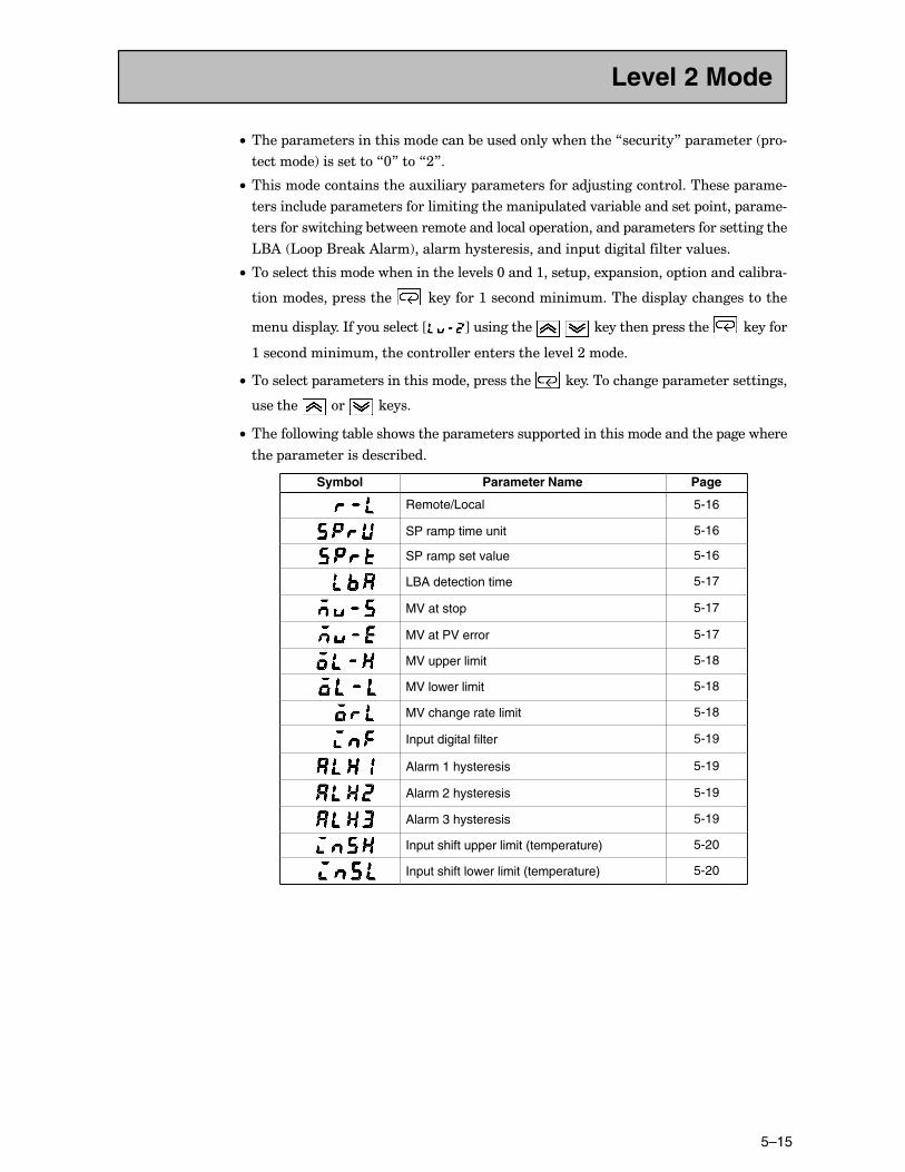
5–15
C• ���� ��������������������������&�������������������7�������8� ��������� �#
��������!����������7@8���7;8�
C• ����������������������1������� ���������������5������������������� �����#
������������ ������������������������������ ������.����&����������� ����� �����#
������������������&���������������������� ������������ ������������������������
'()� ' �(�����)����!�������������������������� �����������������.�����
C• ��������������������������������.����@�����:����� ���1 ������� ������������&��#
���������� ��������� ��������:���������������������� �����������������
������� �����*�����������J K���������� � ���������� ��������� �������
:�����������������������������������������.���;�����
C• ��������� ����������������������� ��������� ��������������� ������������������
������� ��� ������
C• ��������������&������������ ����������� ������������������������� ���������
���� ������������������&���
Symbol Parameter Name Page
Remote/Local 5-16
SP ramp time unit 5-16
SP ramp set value 5-16
LBA detection time 5-17
MV at stop 5-17
MV at PV error 5-17
MV upper limit 5-18
MV lower limit 5-18
MV change rate limit 5-18
Input digital filter 5-19
Alarm 1 hysteresis 5-19
Alarm 2 hysteresis 5-19
Alarm 3 hysteresis 5-19
Input shift upper limit (temperature) 5-20
Input shift lower limit (temperature) 5-20
Level 2 Mode
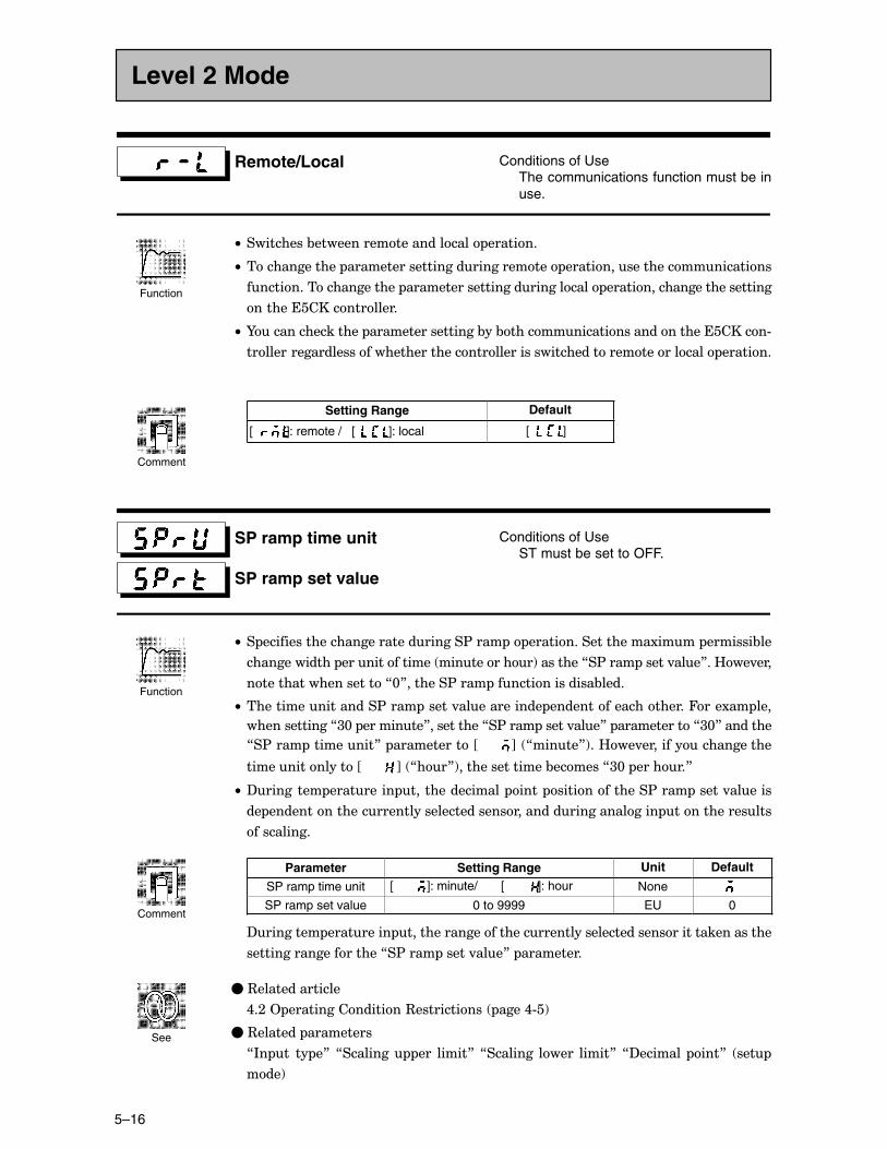
CHAPTER 5 PARAMETERS
5–16
Remote/Local Conditions of UseThe communications function must be inuse.
C• ���������&���������������������� �������
C• ������������� ����������������������������� ��������������������������
��������������������� ���������������������������� ��������������������������
��������������������
C• I��������������� �����������������&��&��������������������������������#
�������������������������������������������������������������������� �������
Setting Range Default
[ ]: remote / [ ]: local [ ]
SP ramp time unit
SP ramp set value
Conditions of UseST must be set to OFF.
C• � �������������������������������$���� � ������������������1���� �������&��
������������� �������������� ����������!��������7�$���� �����.���8��B��.���
��������������������7@8�������$���� ���������������&����
C• ������������������$���� �����.������������ ��������������������4���1�� ���
�������������7<@� ��������8����������7�$���� �����.���8� �����������7<@8��������
7�$���� ���������8� �����������JCCCCCC K� 7�����8!��B��.�������������������
���������������JCCCCCC K� 7��8!���������������&������7<@� ������8
C• ?�������� ��������� ��������������� ���� �������������$���� �����.������
�� �������������������������������������������������������� ��������������
����������
Parameter Setting Range Unit Default
SP ramp time unit [ ]: minute/ [ ]: hour None
SP ramp set value 0 to 9999 EU 0
?�������� ��������� ����������������������������������������������������������
���������������������7�$���� �����.���8� ���������
�C3��������������
,�;�2 ����������������3����������� ����,#�!
�C3������� ���������
7*� �� �� �8� 7�������� ��� �����8�7�������� ����� �����8�7?������� ���8� ���
���!
Level 2 Mode
Function
Comment
Function
Comment
See
5–17
LBA detection time Conditions of UseThe LBA (Loop Break Alarm) functionmust be assigned as an output.
C• ����� ����������������������������&��)���1������
C• ����'()����� ���������������������������� ������.����������&����@�;�D���#�����
����������� ������������� ���������������������� ������.����&�����������������7%A
��������8���7%A�����������8� ����������
C• ����'()���������������&�������������� ������������������7@8�
Setting Range Unit Default
0 to 9999 Second 0
�C3��������������
,�,�'()� ����,#G!
>�<�B����"��������2� �� ����>#�!
�C3������� ���������
7)���1����=������8� ��.���:����!
7������� ��:�����������8�7������� ��;�����������8�7)1�������� ��:
����������8� ��� ����!
MV at stop
MV at PV error
C• ����7%A������ 8� ���������������������� ������.����&�������� ��������� ��
C• ����7%A����$A�����8� ���������������������� ������.����&������������� ������
�����
C• ������������������������������������������������������������������������������#
����
C• �������� ������.����&�����������������������������������������������������
�1 ������������������.��.����
Control Method Setting Range Unit Default
Standard -5.0 to 105.0 % 0Heating and cooling -105.0 to 105.0 % 0
�C3���������������
%A������ ��<�/���������������� ����2 ������� ����<#::!
%A����$A����� ��>�;�B����"������������?�� ���� ����>#<!
Level 2 Mode
Function
Comment
See
Function
Comment
See
CHAPTER 5 PARAMETERS
5–18
MV upper limit
MV lower limit
MV change rate limit
Conditions of UseThe control must be advanced PID con-trol, and ST must be set to OFF.
C• ����7%A� ��������8�����7%A�����������8� ������������������ ���������������#
�������������� ������.����&����9������������ ������.����&�������������&�����
����������������������������� ��#��������#����������������� ����������
����������������������� �������������� ������ ����.����
C• ����7%A������������������8� ��������������������1���� �������&���������������
��� �������� �������� ������.����&���� *�� �� ������� ��� �������� ������.����&��
����������� �������������������&���1����������������������.��������������������
�������������.����&������ ��#������.���������������� ���������
����7%A������������������8���������������&�������������� ������������������7@�@8�
C• %A� ��������
���������������������������������������������������������������������������#
��������)������������ ������.����&��������������������������������������������
����������1 ������������������.��.����
Control Method Setting Range Unit Default
Standard MV lower limit +0.1 to 105.0 % 105.0Heating and cooling 0.0 to 105.0 % 105.0
C• %A�����������
���������������������������������������������������������������������������#
��������)������������ ������.����&��������������������������������������������
����������1 ������������������.��.����
Control Method Setting Range Unit Default
Standard -5.0 to MV upper limit -0.1 % -5.0Heating and cooling -105.0 to 0.0 % -105.0
C• %A������������������
Setting Range Unit Default
0.0 to 100.0 % 0.0
�C3��������������
,�;�2 ����������������3����������� ����,#,!
Level 2 Mode
Function
Comment
See
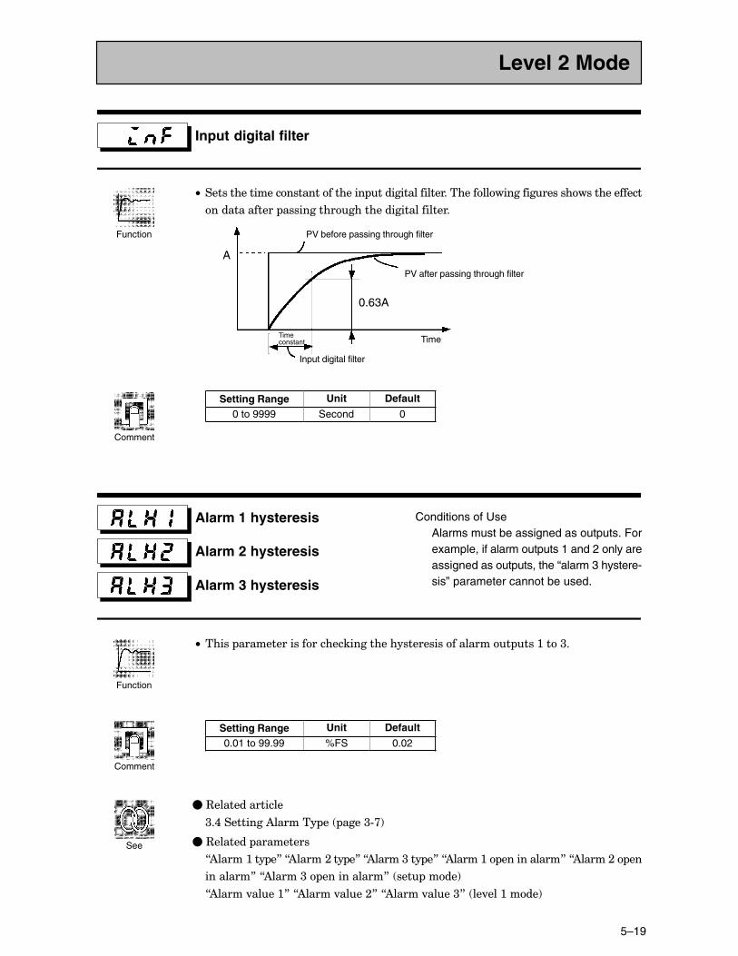
5–19
Input digital filter
C• ������������������������������ ����������������������������������������������������
������������� ��������������������������������
A
PV before passing through filter
PV after passing through filter
0.63A
Input digital filter
Time constant Time
Setting Range Unit Default
0 to 9999 Second 0
Alarm 1 hysteresis
Alarm 2 hysteresis
Alarm 3 hysteresis
Conditions of UseAlarms must be assigned as outputs. Forexample, if alarm outputs 1 and 2 only areassigned as outputs, the “alarm 3 hystere-sis” parameter cannot be used.
C• ����� ������������������������������������������������ ���:���<�
Setting Range Unit Default
0.01 to 99.99 %FS 0.02
�C3��������������
<�,���������)������� �� ����<#>!
�C3������� ���������
7)�����:��� �8�7)�����;��� �8�7)�����<��� �8�7)�����:� �����������8�7)�����;� ��
��������8�7)�����<� �����������8� ��� ����!
7)�����.����:8�7)�����.����;8�7)�����.����<8� ��.���:����!
Level 2 Mode
Function
Comment
Function
Comment
See
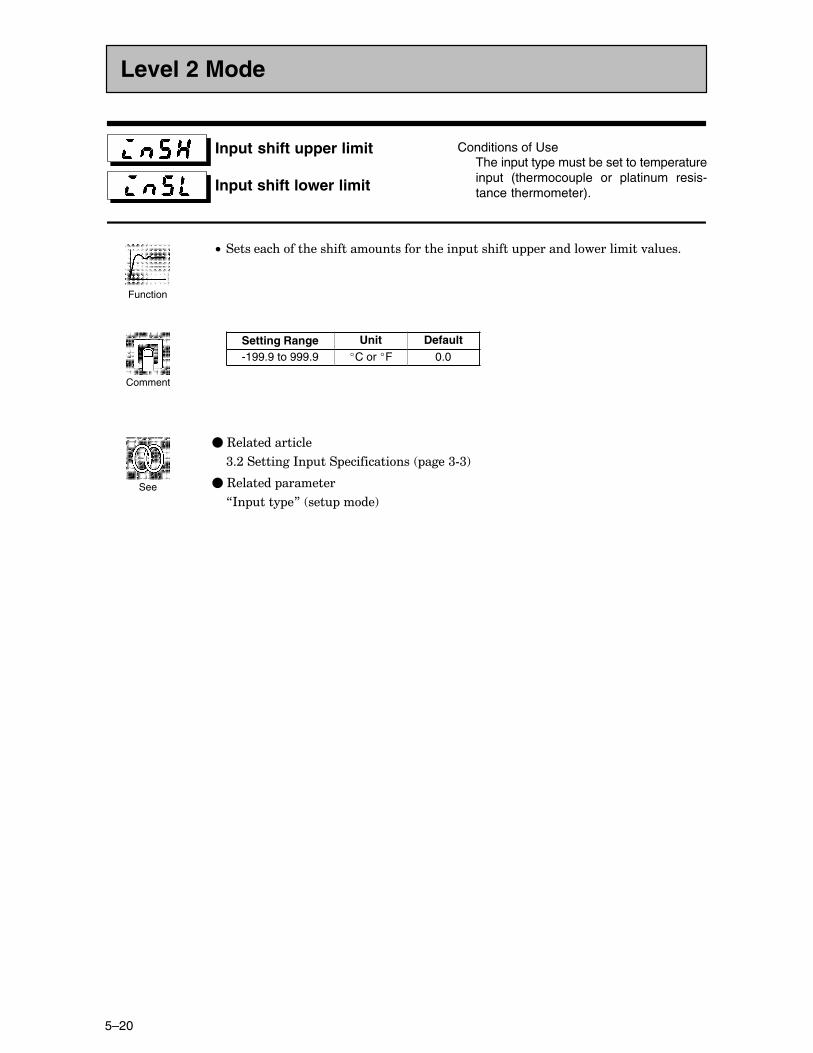
CHAPTER 5 PARAMETERS
5–20
Input shift upper limit
Input shift lower limit
Conditions of UseThe input type must be set to temperatureinput (thermocouple or platinum resis-tance thermometer).
C• ������������������������������������� �������� ������������������.�����
Setting Range Unit Default-199.9 to 999.9 �C or �F 0.0
�C3��������������
<�;���������*� ��� ������������ ����<#<!
�C3������� ��������
7*� ���� �8� ��� ����!
Level 2 Mode
Function
Comment
See
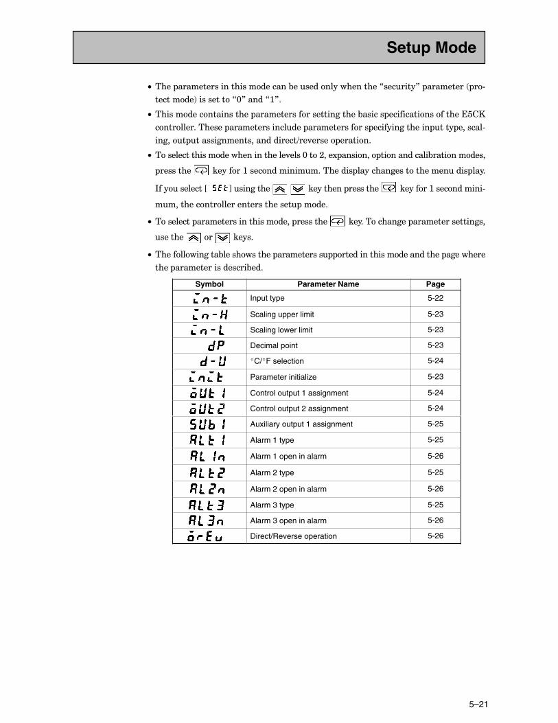
5–21
C• ���� ��������������������������&�������������������7�������8� ��������� �#
��������!����������7@8�����7:8�
C• ��������������������� �������������������������&������ ����������������������
���������������� ����������������� �������������� ��������������� ���� �������#
������ �������������������������=��.����� �������
C• ��������������������������������.����@���;���1 ������� ������������&�����������
��������� ��������:���������������������� ������������������������� ����
*�����������JCC K���������� � ���������� ��������� ��������:�����������#
������������������������������� �����
C• ��������� ����������������������� ��������� ��������������� ������������������
������� ��� ������
C• ��������������&������������ ����������� ������������������������� ���������
���� ������������������&���
Symbol Parameter Name Page
Input type 5-22
Scaling upper limit 5-23
Scaling lower limit 5-23
Decimal point 5-23
�C/�F selection 5-24
Parameter initialize 5-23
Control output 1 assignment 5-24
Control output 2 assignment 5-24
Auxiliary output 1 assignment 5-25
Alarm 1 type 5-25
Alarm 1 open in alarm 5-26
Alarm 2 type 5-25
Alarm 2 open in alarm 5-26
Alarm 3 type 5-25
Alarm 3 open in alarm 5-26
Direct/Reverse operation 5-26
Setup Mode
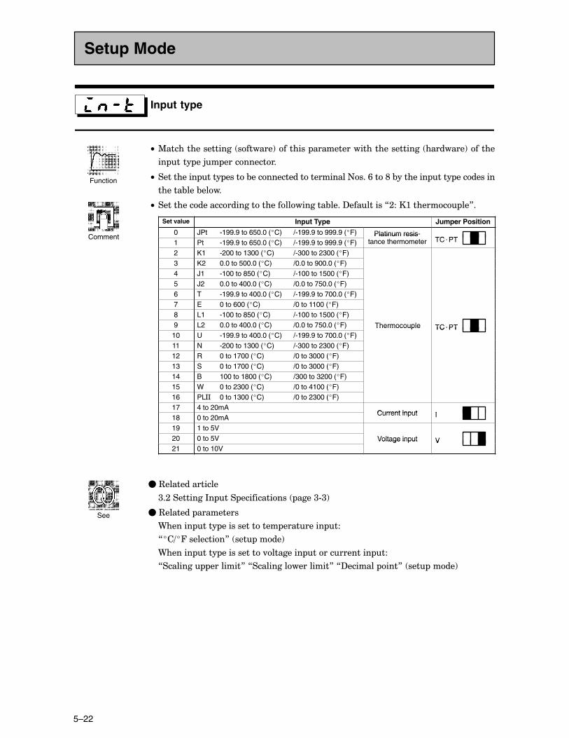
CHAPTER 5 PARAMETERS
5–22
Input type
C• %����������������� �������!�������� �������������������������� ��������!������
�� ���� ��5� �����������
C• ���������� ���� �����&����������������������+���/���E�&�������� ���� ���������
������&���&����
C• �������������������������������������&����?���������7;���:������� ��8�
Set value Input Type Jumper Position
0 JPt -199.9 to 650.0 (�C) /-199.9 to 999.9 (�F) Platinum resis-TC PT1 Pt -199.9 to 650.0 (�C) /-199.9 to 999.9 (�F)
Platinum resistance thermometer TC�PT
2 K1 -200 to 1300 (�C) /-300 to 2300 (�F)3 K2 0.0 to 500.0 (�C) /0.0 to 900.0 (�F)4 J1 -100 to 850 (�C) /-100 to 1500 (�F)5 J2 0.0 to 400.0 (�C) /0.0 to 750.0 (�F)6 T -199.9 to 400.0 (�C) /-199.9 to 700.0 (�F)7 E 0 to 600 (�C) /0 to 1100 (�F)8 L1 -100 to 850 (�C) /-100 to 1500 (�F)9 L2 0.0 to 400.0 (�C) /0.0 to 750.0 (�F) Thermocouple TC�PT10 U -199.9 to 400.0 (�C) /-199.9 to 700.0 (�F)
Thermocouple TC�PT
11 N -200 to 1300 (�C) /-300 to 2300 (�F)12 R 0 to 1700 (�C) /0 to 3000 (�F)13 S 0 to 1700 (�C) /0 to 3000 (�F)14 B 100 to 1800 (�C) /300 to 3200 (�F)15 W 0 to 2300 (�C) /0 to 4100 (�F)16 PL** 0 to 1300 (�C) /0 to 2300 (�F)17 4 to 20mA
Current input I18 0 to 20mACurrent input I
19 1 to 5V20 0 to 5V Voltage input V21 0 to 10V
Voltage input V
�C3��������������
<�;���������*� ��� ������������ ����<#<!
�C3������� ���������
9������ ���� �������������� ��������� ��
7��=�4���������8� ��� ����!
9������ ���� �����������.�������� ������������� ���
7�������� ��������8�7������������������8�7?������� ���8� ��� ����!
Setup Mode
Function
Comment
See
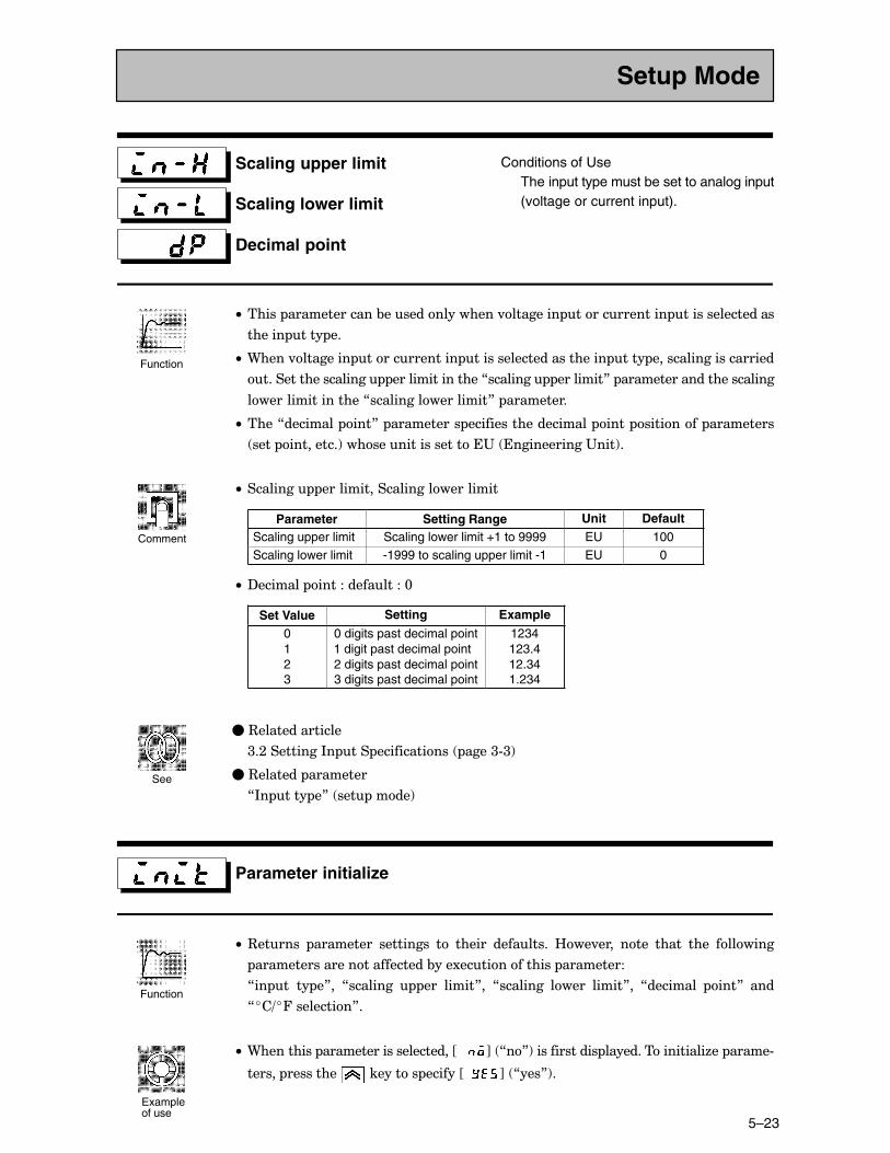
5–23
Scaling upper limit
Scaling lower limit
Decimal point
Conditions of UseThe input type must be set to analog input(voltage or current input).
C• ����� �������������&���������������.�������� ������������� ����������������
������ ���� ��
C• 9����.�������� ������������� ����������������������� ���� ���������������������
������������������� ����������������7�������� ��������8� ������������������������
������������������7������������������8� ���������
C• ����7�������� ���8� ���������� �������������������� ���� �������� ���������
���� ���������!��������������������"� ������������"���!�
C• �������� ����������������������������
Parameter Setting Range Unit DefaultScaling upper limit Scaling lower limit +1 to 9999 EU 100Scaling lower limit -1999 to scaling upper limit -1 EU 0
C• ?������� ���������������@
Set Value Setting Example
0123
0 digits past decimal point1 digit past decimal point2 digits past decimal point3 digits past decimal point
1234123.412.341.234
�C3��������������
<�;���������*� ��� ������������ ����<#<!
�C3������� ��������
7*� ���� �8� ��� ����!
Parameter initialize
C• 3������ ��������� ��������� �� ������ ��������� B��.���� ���� ����� ���� �������
��������������������������&���1������������� ���������
7�� �� �� �8�� 7�������� ��� �����8�� 7�������� ����� �����8�� 7�������� ���8� ���
7��=�4���������8�
C• 9��������� ����������������������JCCC K� 7�8!������������� �����������������6�� �����#
������ ��������� �������� ������JCC K� 7���8!�
Setup Mode
Function
Comment
See
Function
Example of use
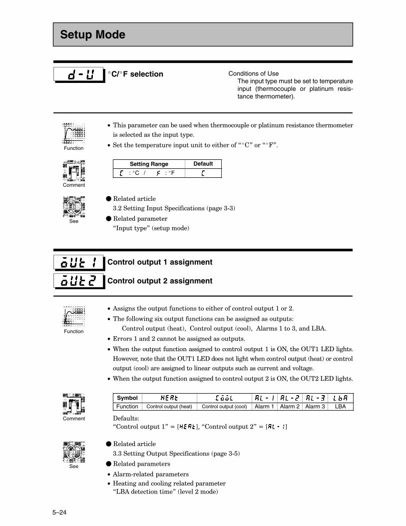
CHAPTER 5 PARAMETERS
5–24
�C/�F selection Conditions of UseThe input type must be set to temperatureinput (thermocouple or platinum resis-tance thermometer).
C• ����� �������������&����������������� ����� ����������������������������
��������������������� ���� ��
C• ����������� ��������� �����������������7��8���7�48�
Setting Range Default
: �C / : �F
�C3��������������
<�;���������*� ��� ������������ ����<#<!
�C3������� ��������
7*� ���� �8� ��� ����!
Control output 1 assignment
Control output 2 assignment
C• )������������ ���������������������������� ��:���;�
C• ��������������1�� ��������������&��������������� ���
������� �� ����!���������� �� ��!���)������:���<������'()�
C• ������:�����;�������&��������������� ���
C• 9��������� ��������������������������� ��:����2+������2"�:�'�?��������
B��.�����������������2"�:�'�?�������������������������� �� ����!��������
� �� ��!������������������������ ���������������������.������
C• 9��������� ��������������������������� ��;����2+������2"�;�'�?��������
Symbol
Function Control output (heat) Control output (cool) Alarm 1 Alarm 2 Alarm 3 LBA
?�������
7������� ��:8�N�J K��7������� ��;8�N�J K
�C3��������������
<�<���������2� ��� ������������ ����<#�!
�C3������� ���������
C• )����#�������� ���������
C• B������������������������� ��������
7'()��������������8� ��.���;����!
Setup Mode
Function
Comment
See
Function
Comment
See
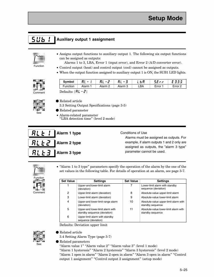
5–25
Auxiliary output 1 assignment
C• )�������� �������������1�������� ��:����������������1�� ���������
����&��������������� ���
)������:���<��'()�������:� �� ������!�����������;� )=?���.����������!�
C• ������� �� ����!������������ �� ��!�������&��������������� ���
C• 9��������� ���������������������1�������� ��:����2+�������"(:�'�?��������
Symbol
Function Alarm 1 Alarm 2 Alarm 3 LBA Error 1 Error 2
?��������J K
�C3��������������
<�<���������2� ��� ������������ ����<#�!
�C3������� ��������
C• )����#�������� ��������7'()��������������8� ��.���;����!�
Alarm 1 type
Alarm 2 type
Alarm 3 type
Conditions of UseAlarms must be assigned as outputs. Forexample, if alarm outputs 1 and 2 only areassigned as outputs, the ”alarm 3 type”parameter cannot be used.
C• 7)�����:���<��� �8� ����������� ���������� �������������������&��������������
����.����������������������&����4������������ ������������������������ ����<#>�
Set Value Settings Set Value Settings1 Upper-and lower-limit alarm
(deviation)7 Lower-limit alarm with standby
sequence (deviation)
2 Upper-limit alarm (deviation) 8 Absolute-value upper-limit alarm
3 Lower-limit alarm (deviation) 9 Absolute-value lower-limit alarm
4 Upper-and lower-limit range alarm(deviation)
10 Absolute-value upper-limit alarm withstandby sequence
5 Upper-and lower-limit alarm withstandby sequence (deviation)
11 Absolute-value lower-limit alarm withstandby sequence
6 Upper-limit alarm with standbysequence (deviation)
?��������?�.������ ��������
�C3��������������
<�,���������)������� �� ����<#>!
�C3������� ���������
7)�����.����:8�7)�����.����;8�7)�����.����<8� ��.���:����!
7)�����:�����������8�7)�����;�����������8�7)�����<�����������8� ��.���;����!
7)�����:� �����������8�7)�����;� �����������8�7)�����<� �����������8�7�����
� ��:�����������8�7������� ��;�����������8� ��� ����!
Setup Mode
Function
Comment
See
Function
Comment
See
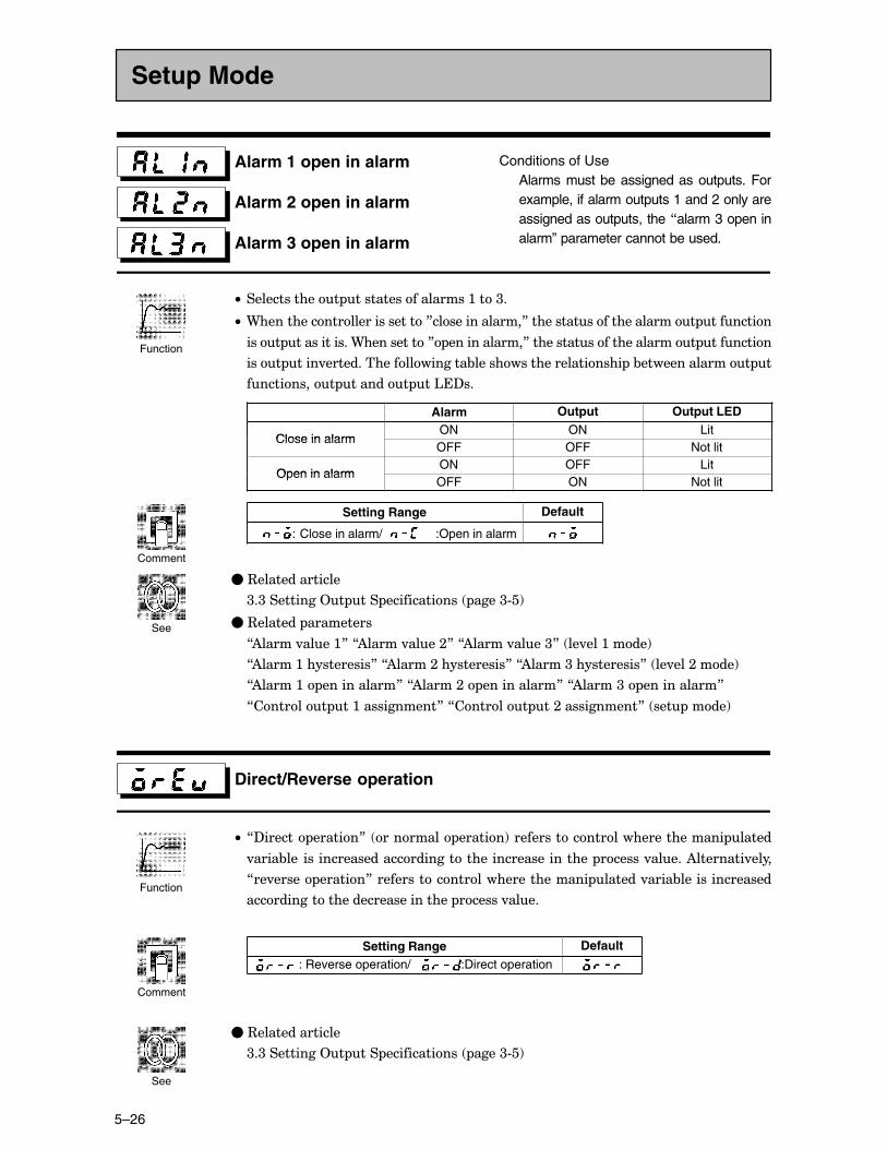
CHAPTER 5 PARAMETERS
5–26
Alarm 1 open in alarm
Alarm 2 open in alarm
Alarm 3 open in alarm
Conditions of UseAlarms must be assigned as outputs. Forexample, if alarm outputs 1 and 2 only areassigned as outputs, the 7alarm 3 open inalarm” parameter cannot be used.
C• ������������� ������������������:���<�
C• 9��������������������������8��������������8������������������������ ��������
���� ������������9����������8 ������������8������������������������ ��������
���� ����.���������������������&���������������������� �&�������������� �
���������� ������� ��'�?��
Alarm Output Output LED
Close in alarmON ON Lit
Close in alarmOFF OFF Not lit
Open in alarmON OFF Lit
Open in alarmOFF ON Not lit
Setting Range Default
:�Close in alarm/ :Open in alarm
�C3��������������
<�<���������2� ��� ������������ ����<#�!
�C3������� ���������
7)�����.����:8�7)�����.����;8�7)�����.����<8� ��.���:����!
7)�����:�����������8�7)�����;�����������8�7)�����<�����������8� ��.���;����!
7)�����:� �����������8�7)�����;� �����������8�7)�����<� �����������8
7������� ��:�����������8�7������� ��;�����������8� ��� ����!
Direct/Reverse operation
C• 7?������ ������8� �������� ������!������������������������������ �����
.����&����������������������������������������������� ������.�����)��������.����
7��.����� ������8������������������������������ ������.����&���������������
������������������������������� ������.����
Setting Range Default
: Reverse operation/ :Direct operation
�C3��������������
<�<���������2� ��� ������������ ����<#�!
Setup Mode
Function
Comment
See
Function
Comment
See
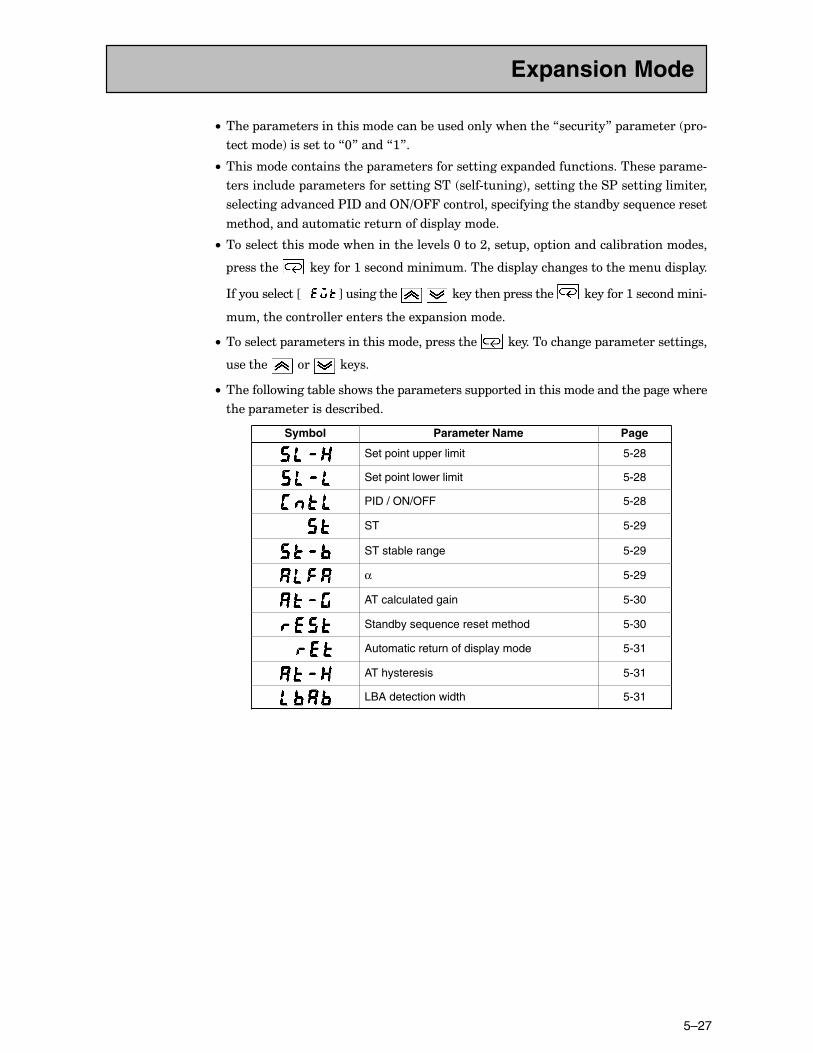
5–27
C• ���� ��������������������������&�������������������7�������8� ��������� �#
��������!����������7@8�����7:8�
C• ��������������������� ����������������������1 ��������������������� �����#
������������ ������������������������ ����#�����!���������������$�����������������
������������.������$*?�����2+=244��������� ������������������&����-����������
������������������������������ ��������
C• ��������������������������������.����@���;����� �� ������������&�����������
��������� ��������:���������������������� ������������������������� ����
*�����������JCCC K���������� � ���������� ��������� ��������:�����������#
�����������������������������1 ����������
C• ��������� ����������������������� ��������� ��������������� ������������������
������� ��� ������
C• ��������������&������������ ����������� ������������������������� ���������
���� ������������������&���
Symbol Parameter Name Page
Set point upper limit 5-28
Set point lower limit 5-28
PID / ON/OFF 5-28
ST 5-29
ST stable range 5-29
α 5-29
AT calculated gain 5-30
Standby sequence reset method 5-30
Automatic return of display mode 5-31
AT hysteresis 5-31
LBA detection width 5-31
Expansion Mode
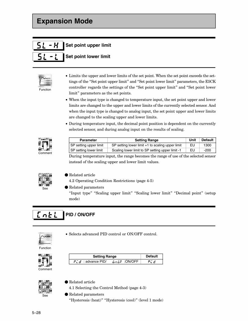
CHAPTER 5 PARAMETERS
5–28
Set point upper limit
Set point lower limit
C• '���������� ����������������������������� �����9������������ �����1�������������#
������������7���� ���� ��������8�����7���� ��������������8� �������������������
������������������������������������7���� ���� ��������8�����7���� ��������
�����8� ��������������������� �����
C• 9���������� ���� ������������������ ��������� ����������� ���� �����������
������������������������� ��������������������������������������������������)��
����������� ���� ����������������������� ����������� ���� ������������������
�������������������������� �������������������
C• ?�������� ��������� ��������������� ���� ����������� ���������������������
���������������������������������� �������������������������
Parameter Setting Range Unit Default
SP setting upper limit SP setting lower limit +1 to scaling upper limit EU 1300SP setting lower limit Scaling lower limit to SP setting upper limit -1 EU -200
?�������� ��������� �������������&�����������������������������������������
���������������������� ������������������.�����
�C3��������������
,�;�2 ����������������3����������� ����,#�!
�C3������� ���������
7*� �� �� �8� 7�������� ��� �����8�7�������� ����� �����8�7?������� ���8� ���
���!
PID / ON/OFF
C• ����������.������$*?���������2+=244�������
Setting Range Default
: advance PID/ :ON/OFF
�C3��������������
,�:���������������������%����� ����,#<!
�C3������� ���������
7B���������� ����!8�7B���������� ��!8� ��.���:����!
Expansion Mode
Function
Comment
See
Function
Comment
See
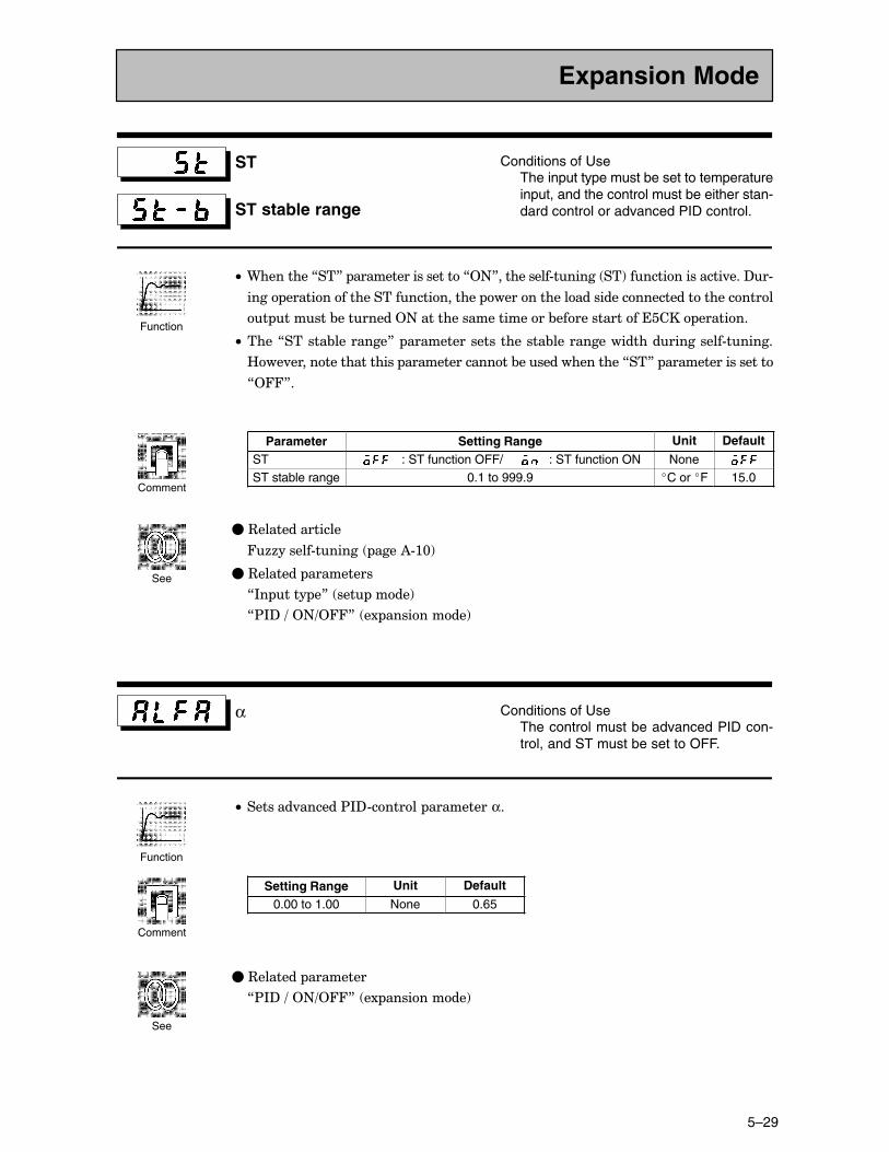
5–29
ST
ST stable range
Conditions of UseThe input type must be set to temperatureinput, and the control must be either stan-dard control or advanced PID control.
C• 9��������7��8� ������������������72+8����������#������ ��!���������������.���?�#
���� ���������������������������� ���������������������������������������
� ������&��������2+��������������������&������������������ �������
C• ����7������&��������8� ���������������������&�������������������������#������
B��.������������������ ���������������&���������������7��8� �����������������
72448�
Parameter Setting Range Unit Default
ST : ST function OFF/ : ST function ON NoneST stable range 0.1 to 999.9 �C or �F 15.0
�C3��������������
466������#������ ����)#:@!
�C3������� ���������
7*� ���� �8� ��� ����!
7$*?�=�2+=2448� �1 ���������!
α Conditions of UseThe control must be advanced PID con-trol, and ST must be set to OFF.
C• �������.������$*?#������ ���������α�
Setting Range Unit Default
0.00 to 1.00 None 0.65
�C3������� ��������
7$*?�=�2+=2448� �1 ���������!
Expansion Mode
Function
Comment
See
Function
Comment
See
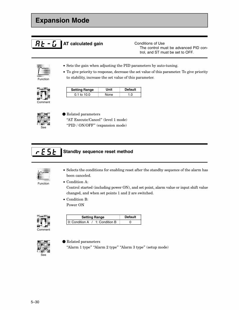
CHAPTER 5 PARAMETERS
5–30
AT calculated gain ��������������
The control must be advanced PID con-trol, and ST must be set to OFF.
C• ���������������������5����������$*?� ����������&����#������
C• ����.�� ������������ ����������������������.����������� ��������������.�� ������
�����&������������������������.����������� ���������
Setting Range Unit Default
0.1 to 10.0 None 1.0
�C3������� ���������
7)���1����=������8� ��.���:����!
7$*?�=�2+=2448� �1 ���������!
Standby sequence reset method
C• ���������������������������&��������������������������&����-��������������������
&�������������
C• ��������)�
�������������� ��������� ����2+!���������� �����������.�������� ��������.���
���������������������� �����:�����;��������������
C• ��������(�
$����2+
Setting Range Default
0: Condition A / 1: Condition B 0
�C3������� ���������
7)�����:��� �8�7)�����;��� �8�7)�����<��� �8� ��� ����!
Expansion Mode
Function
Comment
See
Function
Comment
See
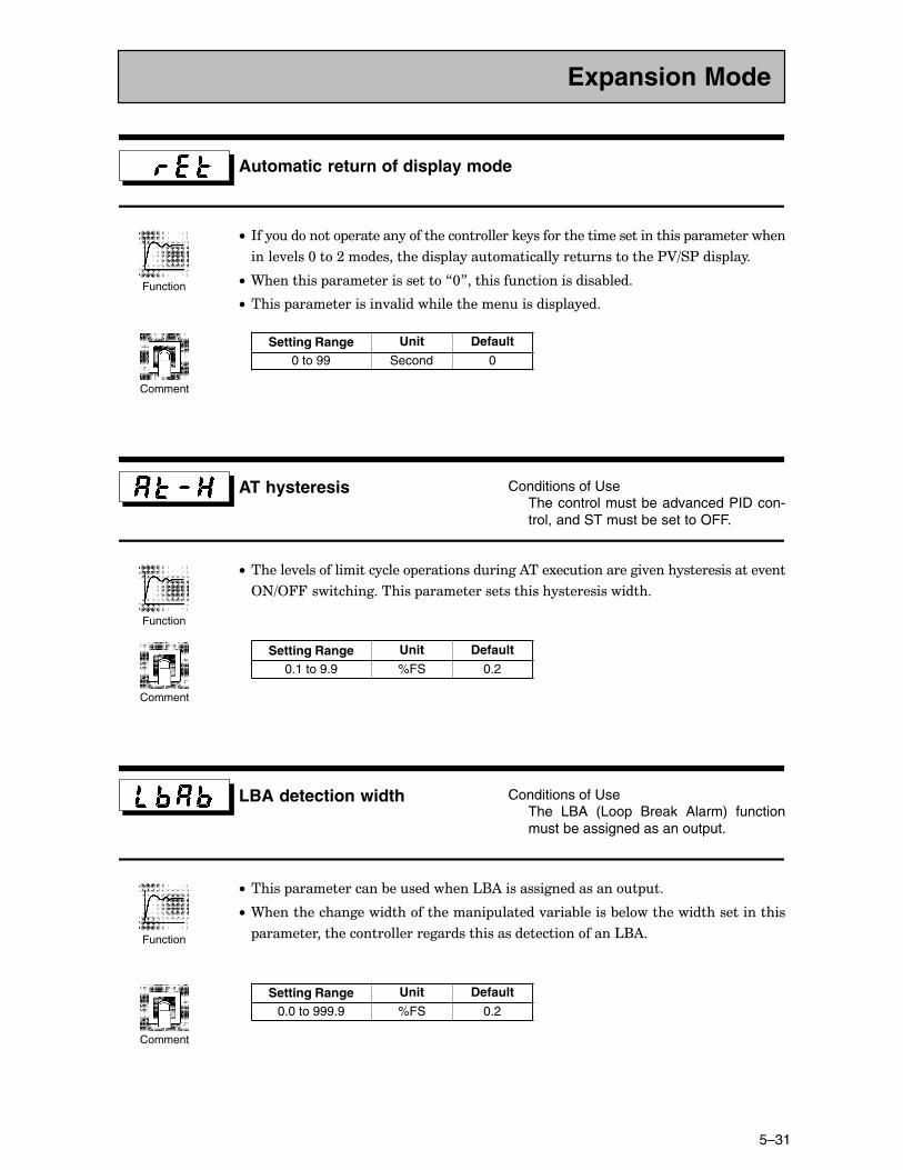
5–31
Automatic return of display mode
C• *��������� ������������������������������������������������������ �������������
�����.����@���;�������������� �����������������������������$A=�$���� ����
C• 9��������� ������������������7@8���������������������&����
C• ����� ��������������.������������������������� ������
Setting Range Unit Default
0 to 99 Second 0
AT hysteresis Conditions of UseThe control must be advanced PID con-trol, and ST must be set to OFF.
C• ������.������������������ ��������������)���1������������.������������������.���
2+=244����������������� ������������������������������������
Setting Range Unit Default
0.1 to 9.9 %FS 0.2
LBA detection width Conditions of UseThe LBA (Loop Break Alarm) functionmust be assigned as an output.
C• ����� �������������&�����������'()�������������������� ��
C• 9������������������������������� ������.����&������&�������������������������
�����������������������������������������������������'()�
Setting Range Unit Default
0.0 to 999.9 %FS 0.2
Expansion Mode
Function
Comment
Function
Comment
Function
Comment
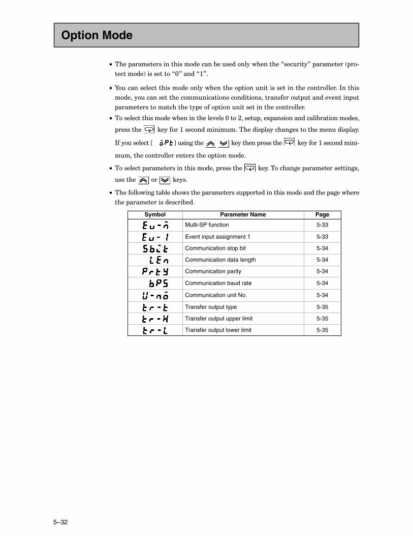
CHAPTER 5 PARAMETERS
5–32
C• ���� ��������������������������&�������������������7�������8� ��������� �#
��������!����������7@8�����7:8�
C• I���������������������������������� ��������������������������������*������
��������������������������������������������������� �������.������ �
������������������������ ���� ����������������������������
C• ��������������������������������.����@���;����� ���1 ��������������&�����������
��������� ��������:���������������������� ������������������������� ����
*�����������JCCCC K���������� � ���������� ��������� ��������:�����������#
���������������������������� ��������
C• ��������� ����������������������� ��������� ��������������� ������������������
������� ��� ������
C• ��������������&������������ ����������� ������������������������� ���������
���� ������������������&���
Symbol Parameter Name Page
Multi-SP function 5-33
Event input assignment 1 5-33
Communication stop bit 5-34
Communication data length 5-34
Communication parity 5-34
Communication baud rate 5-34
Communication unit No. 5-34
Transfer output type 5-35
Transfer output upper limit 5-35
Transfer output lower limit 5-35
Option Mode
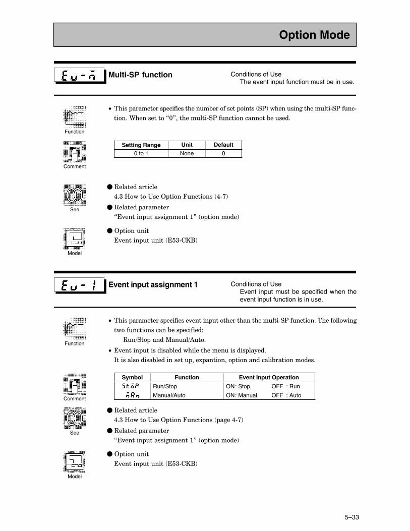
5–33
Multi-SP function Conditions of UseThe event input function must be in use.
C• ����� ���������� ��������������&��������� ����� �$!�������������������#�$����#
�����9����������7@8����������#�$��������������&������
Setting Range Unit Default
0 to 1 None 0
�C3��������������
,�<�B����"���2 ����4������� ,#>!
�C3������� ��������
7�.������ �������������:8� �������!
�C2 �������
�.������ ������ ��<#��(!
Event input assignment 1 Conditions of UseEvent input must be specified when theevent input function is in use.
C• ����� ���������� ���������.������ ��������������������#�$��������������������
���������������&��� ��������
3�=�� �����%����=)��
C• �.������ ���������&������������������������ ������
*�������������&����������� ���1 ������� ������������&�����������
Symbol Function Event Input Operation
Run/Stop ON: Stop, OFF : Run
Manual/Auto ON: Manual, OFF : Auto
�C3��������������
,�<�B����"���2 ����4������� ����,#>!
�C3������� ��������
7�.������ �������������:8� �������!
�C2 �������
�.������ ������ ��<#��(!
Option Mode
Function
Comment
See
Model
Function
Comment
See
Model
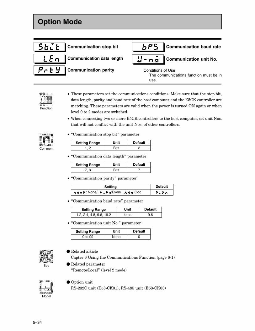
CHAPTER 5 PARAMETERS
5–34
Communication stop bit
Communication data length
Communication parity
Communication baud rate
Communication unit No.
Conditions of UseThe communications function must be inuse.
C• ������ ����������������������������������������%������������������� �&���
������������� ����������&�������������������� �����������������������������
���������������� ��������������.�������������� �������������2+�������������
��.���@���;�������������������
C• 9�������������������������������������������������� �������������+��
����������������������������������+��������������������
C• 7������������� �&��8� ��������
Setting Range Unit Default1, 2 Bits 2
C• 7����������������������8� ��������
Setting Range Unit Default
7, 8 Bits 7
C• 7����������� �����8� ��������
Setting Default
: None/ :Even/ :Odd
C• 7�����������&�������8� ��������
Setting Range Unit Default
1.2, 2.4, 4.8, 9.6, 19.2 kbps 9.6
C• 7���������������+�8� ��������
Setting Range Unit Default
0 to 99 None 0
�C3��������������
�� ����/�"���������������������4������ ����/#:!
�C3������� ��������
73����='���8� ��.���;����!
�C2 �������
3�#;<;������ ��<#��@:!��3�#,E������ ��<#��@<!
Option Mode
Function
Comment
See
Model
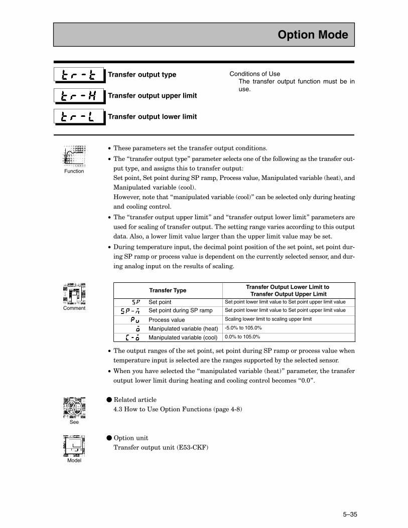
5–35
Transfer output type
Transfer output upper limit
Transfer output lower limit
Conditions of UseThe transfer output function must be inuse.
C• ������ ���������������������������� �����������
C• ����7���������� ���� �8� ���������������������������������������������������#
���� �������������������������������� ��
���� ��������� �����������$���� ��$������.�����%��� ������.����&��� ����!�����
%��� ������.����&��� ��!�
B��.�������������7���� ������.����&��� ��!8�����&����������������������������
����������������
C• ����7���������� �� ��������8�����7���������� ������������8� �������������
��������������������������� ���������������������.����������������������� �
������)�����������������.�������������������� ���������.��������&������
C• ?�������� ��������� ��������������� ���� ���������������� ��������� ������#
�����$���� ��� ������.��������� ��������������������������������������������#
������������ �������������������������
Transfer Type Transfer Output Lower Limit to Transfer Output Upper Limit
Set point Set point lower limit value to Set point upper limit value
Set point during SP ramp Set point lower limit value to Set point upper limit value
Process value Scaling lower limit to scaling upper limit
Manipulated variable (heat) -5.0% to 105.0%
Manipulated variable (cool) 0.0% to 105.0%
C• ����� ������������������� ��������� �����������$���� ��� ������.��������
��� ��������� ������������������������������ �����&���������������������
C• 9��������.���������������7���� ������.����&��� ����!8� ����������������������
� �������������������������������������������&������7@�@8�
�C3��������������
,�<�B����"���2 ����4������� ����,#E!
�C2 �������
���������� ������ ��<#��4!
Option Mode
Function
Comment
See
Model
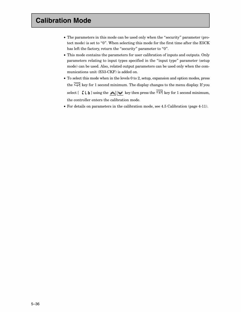
CHAPTER 5 PARAMETERS
5–36
C• ���� ��������������������������&�������������������7�������8� ��������� �#
��������!����������7@8��9�������������������������������������������������������
�������������������������������7�������8� �����������7@8�
C• ��������������������� ���������������������&���������� �������� ����2���
����������������������� ���� ���� ���������������7�� ���� �8� ��������� ���
���!�����&�������)������������� �� ��������������&���������������������#
�������������� ��<#��4!������������
C• ��������������������������������.����@���;����� ���1 ���������� ���������� ����
���� ��������:���������������������� ������������������������� �����*���
�������JCCC K���������� � ���������� ��������� ��������:��������������
����������������������������&����������
C• 4������������ ���������������������&���������������,�������&������ ����,#::!�
Calibration Mode
CHAPTER 6 USING THE COMMUNICATIONS FUNCTION
6–1
CHAPTER 6USING THECOMMUNICATIONSFUNCTION
�������� �����������������&���������������������������� ���
������������������������
CHAPTER6
/�: 2��������
����������������4����� /F;��������������������
2����� /F;��������������������������������������������������������������
��������� ������ /F;������������������������������������������
*�������� /F;������������������������������������������������������������
/�; $�� �������������������� /F<��������������������
��&������������ /F<��������������������������������������������
������������������������
� ����������� /F,����������������������������������������������������
/�< ����������������� /F���������������������������������
/�, ������������3�� ���� /F/����������������������������
3������=�������� ��������� /F/��������������������������
*������� ������������� /FG������������������������������
/�� B����3����������������
�����*�������� /F:@������������������������������������������
"������������� /F::������������������������������������������������
/�/ $�������1�� �� /F:;��������������������������������������������
B������� ������ /F:;��������������������������������������
$����������� ���������*(%�$�! /F:<����������������
�1�� �������� /F:,������������������������������������������������
CHAPTER 6 USING THE COMMUNICATIONS FUNCTION
6–2
6.1 Outline of the Communications Function
���� ������������ ������� ������ �� �� ������ ���� ���� ����
����������&���� ������ �� �������������������������� ������#
������� �� ���� ����� ���������� ����� ��� ���� ������&��� �������� ��
.�������������������� ����
9������������������������������������� �����������3�#;<;���
3�#,E������������������&�������������������������������
�������������������������������������
C• 3������=���������� ���������P
C• 2 �����������������P����
C• ������������������������.���
���������������������������������������������������
C• 9������� �� ���������� ��� ���&��� ��� ������ ������ �������� )���
����������������&�����������������1����������#�����P
C• 9������� �������������� �.����������������������.����9���������������
��������������� �����������������������.���
����������.���:� +������������
����������.���@� 9��������� �������������������� ������1 ����������
������� ���&�����
C• 4����������������������&�����������������.��������� ����/#G�
C• ����7��=�� 8��7�����=����8�����7)���1����=������8� �������������
������������������� �������������� ����������������� ����������
��������
���������� ������������7������������8������������������������
������������������7��� ���������8������ ������������������������
������������&������������ �����*������������������ ������������
����������������������������������
���� �������� �������� ����� ������� �����=��� ���� ������ ���#
�����
Command frame Command frame
Response frame
Host computerE5CK
���� ���� �� ���� �������� �� ������������ ��������� �� ���
3�#;<;����3�#,E������������� ������������
2 ���������� ����������3�#;<;������3�#,E��� ���������������������#
����
C• 2 ��������
��<#��@:� 3�#;<;�!
��<#��@<� 3�#,E�!
�Outline
�Transfer procedure
� Interface
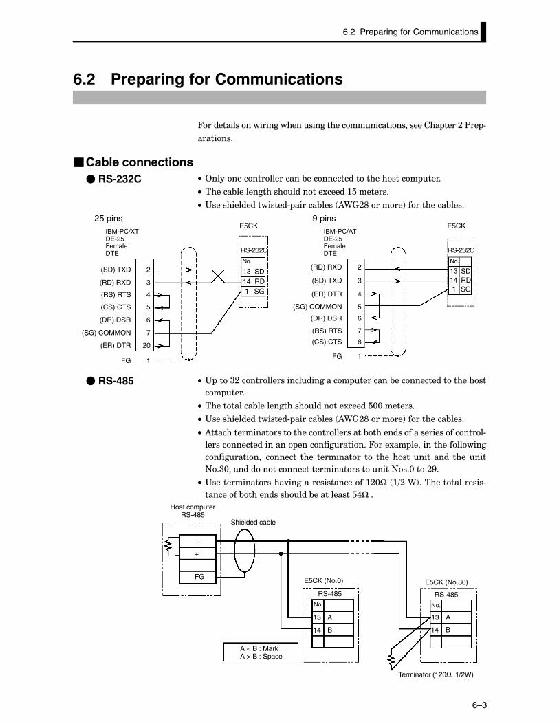
6.2 Preparing for Communications
6–3
6.2 Preparing for Communications
4����������������������������������������������������� ����;�$�� #
��������
�Cable connectionsC• 2��������������������&����������������������� ����
C• ������&�������������������1�����:���������
C• "�������������������# ������&���� )9Q;E������!����������&����
RS-232C
No.
13 SDRD14
1 SG
E5CK
RS-232C
No.
13 SDRD14
1 SG
E5CKIBM-PC/XTDE-25FemaleDTE
(SD) TXD
(RD) RXD
(RS) RTS
(CS) CTS
(SG) COMMON
(ER) DTR
(DR) DSR
2
3
4
5
20
6
7
FG 1
(RD) RXD
(SD) TXD
(ER) DTR
(SG) COMMON
(RS) RTS
(CS) CTS
(DR) DSR
2
3
4
5
8
6
7
FG 1
25 pinsIBM-PC/ATDE-25FemaleDTE
9 pins
C• " ���<;������������������������ ��������&��������������������
�� ����
C• �����������&�������������������1������@@��������
C• "�������������������# ������&���� )9Q;E������!����������&����
C• )������������������������������������&��������������������������#
�������������������� ���������������4���1�� ������������������
������������ ������� ���� ���������� �� ���� ���� ���� ���� ���� ���
+�<@�����������������������������������+��@���;G�
C• "����������������.�������������������:;@Ω� :=;�9!����������������#
��������&�������������&������������,٠�
-
+
FG
RS-485
No.
13
14
RS-485
No.
13 A
B14
Host computerRS-485
Shielded cable
E5CK (No.0) E5CK (No.30)
Terminator (120Ω 1/2W)
A
B
A < B : MarkA > B : Space
� RS-232C
� RS-485
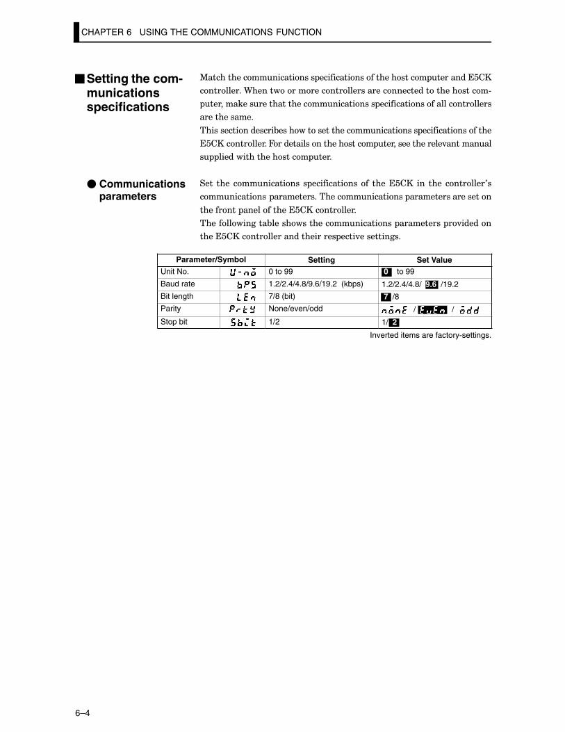
CHAPTER 6 USING THE COMMUNICATIONS FUNCTION
6–4
%���������������������� ������������������������ ������������
����������9������������������������������������������������#
������������������������������������ ���������������������������
�������������
������������������&����������������������������� �����������������
���������������4���������������������� �����������������.���������
� �������������������� ����
���� ���� ������������ � ������������ �� ��������� ��� ���� ��������0�
������������ ��������������������������� �������������������
��������� �������������������������
��������������&������������������������ ���������� �.������
������������������������������� ����.�����������
Parameter/Symbol Setting Set ValueUnit No. 0 to 99 0 to 99
Baud rate 1.2/2.4/4.8/9.6/19.2 (kbps) 1.2/2.4/4.8/ 9.6 /19.2
Bit length 7/8 (bit) 7 /8
Parity None/even/odd / /
Stop bit 1/2 1/ 2
Inverted items are factory-settings.
�Setting the com-municationsspecifications
� Communicationsparameters
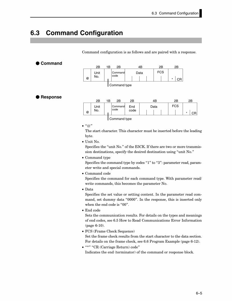
6.3 Command Configuration
6–5
6.3 Command Configuration
�������������������������������������� ���������������� ����
� Command
UnitNo.
Commandcode
Data FCS
CR
Command type
@ *
2B 1B 2B 4B 2B 2B
� Response
UnitNo.
Commandcode
Data FCS
Command type
CR
Endcode
@ *
2B 1B 2B 4B 2B 2B2B
C• 7R8
����������������������������������������&�����������&����������������
&����
C• "����+�
� ������������7����+�8�������������*�����������������������������#
������������������ ����������������������������������7����+�8
C• ��������� �
� ��������������������� ��&�������7:8���7<8�� ��������������� ����#
���������������� ��������������
C• ����������
� ������������������������������������ ���9���� �������������=
��������������������&���������� ���������+�
C• ?���
� ����������������.����������������������*������ ����������������#
��������������������7@@@@8��*��������� ���������� ��� ������������
��������������������7@@8�
C• �������
����������������������������4������������������ ���������������
����������������/���B����3���������������������*��������
����/#:@!�
C• 4��� 4�������������-����!
���������������������������������������������������������������������
4���������������������������������/�/�$�������1�� ��� ����/#:;!�
C• 7S8�7�3� ���������3����!����8
*����������������� ���������!������������������� ����&����
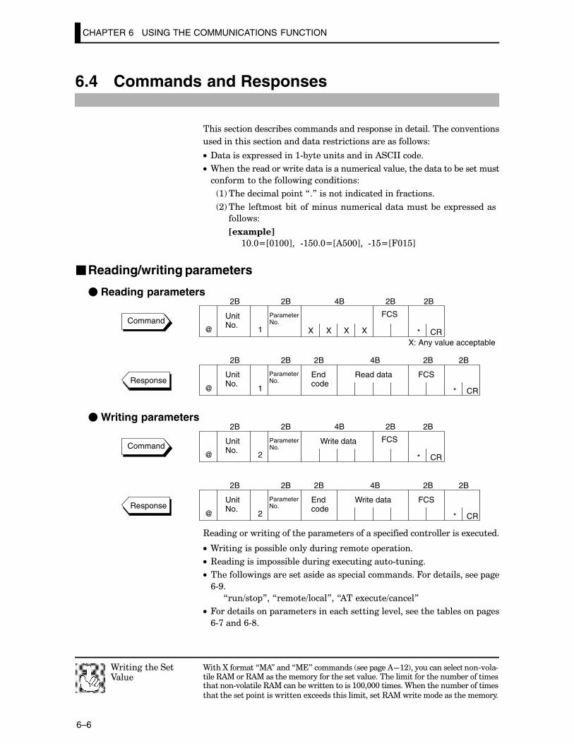
CHAPTER 6 USING THE COMMUNICATIONS FUNCTION
6–6
6.4 Commands and Responses
������������������&������������������ ���������������������.������
�����������������������������������������������������
C• ?��������1 ����������:#&����������������)��**�����
C• 9����������������������������������������.����������������&���������
�����������������������������
:!������������ ����7�8�����������������������������
;!���� ��������&����������������������������&���1 ����������
������
��������
:@�@NJ@:@@K���#:�@�@NJ)�@@K���#:�NJ4@:�K
�Reading/writing parameters
� Reading parameters
Command
ParameterNo.
ParameterNo.
UnitNo.
FCS
CR
UnitNo.
Read data FCS
CR
Endcode
@
@
*
*
2B 2B 4B 2B 2B
2B 2B 4B 2B 2B2B
1 X X X X
1Response
X: Any value acceptable
� Writing parameters
Command
ParameterNo.
ParameterNo.
UnitNo.
Write data FCS
CR
UnitNo.
Write data FCS
CR
Endcode
@
@
*
*
2B 2B 4B 2B 2B
2B 2B 4B 2B 2B2B
2
2Response
3����������������������� ��������������� ���������������������1������
C• 9���������� ���&������������������� �������
C• 3������������ ���&����������1���������#������
C• ������������������������������� ���������������4��������������� ���
/#G�
7��=�� 8��7�����=����8��7)���1����=������8
C• 4������������ ����������������������������.��������������&������ ����
/#>�����/#E�
9����O�������7%)8�����7%�8��������� ���� ����)F:;!�������������t ��#.��#�����3)%���3)%�������������������������.������������������������&�����������������#.�������3)%�����&���������������:@@�@@@��������9����������&����������
������������ ����������������1����������������������3)%������������������������
9��������������A���
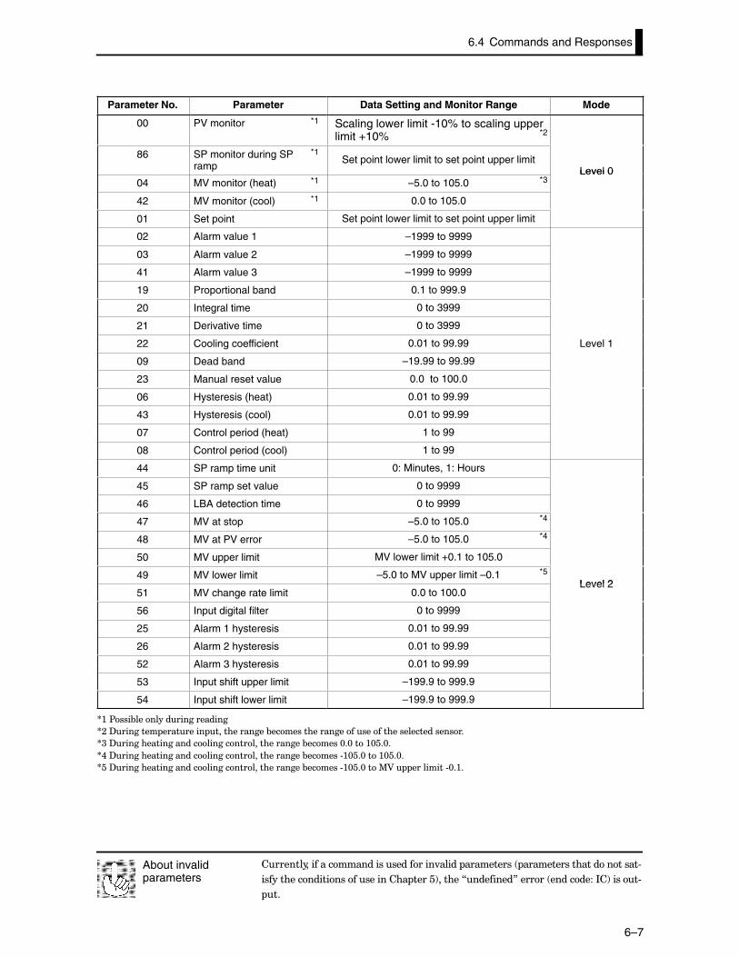
6.4 Commands and Responses
6–7
Parameter No. Parameter Data Setting and Monitor Range Mode
00 PV monitor *1 Scaling lower limit -10% to scaling upperlimit +10%
86 SP monitor during SP *1
rampSet point lower limit to set point upper limit
Level 004 MV monitor (heat) *1 –5.0 to 105.0
Level 0
42 MV monitor (cool) *1 0.0 to 105.0
01 Set point Set point lower limit to set point upper limit
02 Alarm value 1 –1999 to 9999
03 Alarm value 2 –1999 to 9999
41 Alarm value 3 –1999 to 9999
19 Proportional band 0.1 to 999.9
20 Integral time 0 to 3999
21 Derivative time 0 to 3999
22 Cooling coefficient 0.01 to 99.99 Level 1
09 Dead band –19.99 to 99.99
23 Manual reset value 0.0 to 100.0
06 Hysteresis (heat) 0.01 to 99.99
43 Hysteresis (cool) 0.01 to 99.99
07 Control period (heat) 1 to 99
08 Control period (cool) 1 to 99
44 SP ramp time unit 0: Minutes, 1: Hours
45 SP ramp set value 0 to 9999
46 LBA detection time 0 to 9999
47 MV at stop –5.0 to 105.0
48 MV at PV error –5.0 to 105.0
50 MV upper limit MV lower limit +0.1 to 105.0
49 MV lower limit –5.0 to MV upper limit –0.1Level 2
51 MV change rate limit 0.0 to 100.0Level 2
56 Input digital filter 0 to 9999
25 Alarm 1 hysteresis 0.01 to 99.99
26 Alarm 2 hysteresis 0.01 to 99.99
52 Alarm 3 hysteresis 0.01 to 99.99
53 Input shift upper limit –199.9 to 999.9
54 Input shift lower limit –199.9 to 999.9
S:�$���&��������������������
S;�?�������� ��������� �������������&������������������������������������������
S<�?����������������������������������������&������@�@���:@��@�
S,�?����������������������������������������&������#:@��@���:@��@�
S��?����������������������������������������&������#:@��@���%A� ���������#@�:�
����������������������������������.����� ���������� �����������������������#
����������������������������� �����!������7��������8������ ���������*�!�����#
��
About invalidparameters
*2
*3
*4
*4
*5
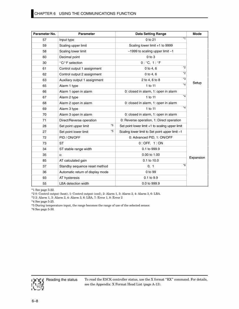
CHAPTER 6 USING THE COMMUNICATIONS FUNCTION
6–8
Parameter No. Parameter Data Setting Range Mode
57 Input type 0 to 21
59 Scaling upper limit Scaling lower limit +1 to 9999
58 Scaling lower limit –1999 to scaling upper limit –1
60 Decimal point 0 to 3
30 �C/�F selection 0 : �C, 1 : �F
61 Control output 1 assignment 0 to 4, 6
62 Control output 2 assignment 0 to 4, 6
63 Auxiliary output 1 assignment 2 to 4, 6 to 8Setup
65 Alarm 1 type 1 to 11Setup
66 Alarm 1 open in alarm 0: closed in alarm, 1: open in alarm
67 Alarm 2 type 1 to 11
68 Alarm 2 open in alarm 0: closed in alarm, 1: open in alarm
69 Alarm 3 type 1 to 11
70 Alarm 3 open in alarm 0: closed in alarm, 1: open in alarm
71 Direct/Reverse operation 0: Reverse operation, 1: Direct operation
28 Set point upper limit *5 Set point lower limit +1 to scaling upper limit
27 Set point lower limit *5 Scaling lower limit to Set point upper limit –1
72 PID / ON/OFF 0: Advanced PID, 1: ON/OFF
73 ST 0 : OFF, 1 : ON
34 ST stable range width 0.1 to 999.9
35 α 0.00 to 1.00Expansion
85 AT calculated gain 0.1 to 10.0Expansion
37 Standby sequence reset method 0, 1
36 Automatic return of display mode 0 to 99
93 AT hysteresis 0.1 to 9.9
55 LBA detection width 0.0 to 999.9
S:����� �����#;;�
S;�@��������� �� ����!��:��������� �� ��!��;��)�����:��<��)�����;��,��)�����<��/��'()�
S<�;��)�����:��<��)�����;��,��)�����<��/��'()��>�������:��E�������;
S,����� �����#;��
S��?�������� ��������� �������������&������������������������������������������
S/����� �����#<@�
���������������������������������������O�������73O8���������4����������
��������) ����1��O�4�����B����'���� ����)#:<!�
Reading the status
*1
*2
*2
*3
*4
*4
*4
*6
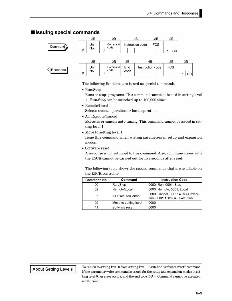
6.4 Commands and Responses
6–9
� Issuing special commands
Commandcode
Commandcode
UnitNo.
Instruction code FCS
CR
UnitNo.
Instruction code FCS
CR
Endcode
@
@
*
*
2B 2B 4B 2B 2B
2B 2B 4B 2B 2B2B
3
3
Command
Response
���������������������������������� ��������������
C• 3�=��
3������� �� ��������������������������&���������������������.��
:���3�=�� �����&����������� ���:@@�@@@�������
C• 3����='���
�������������� �������������� �������
C• )���1����=������
�1������������������#�������������������������&��������������#
�������.���:�
C• %.��������������.���:
*����������������������������� ���������������� ������1 �����
�����
C• �������������
)���� ���������������������������������)��������������������
���������������&�����������������.���������������������
��������������&������������� ������������������������.����&����
������������������
Command No. Command Instruction Code
00 Run/Stop 0000: Run, 0001: Stop02 Remote/Local 0000: Remote, 0001: Local
07 AT Execute/Cancel0000: Cancel, 0001: 40%AT execu-tion, 0002: 100% AT execution
09 Move to setting level 1 000011 Software reset 0000
��������������������.���@���������������.���:�����������7�������������8��������
*������ ����������������������������������������� ������1 �����������������#
�������.���@�������������������������������� @?�N��������������&���1�����!
�����������
About Setting Levels
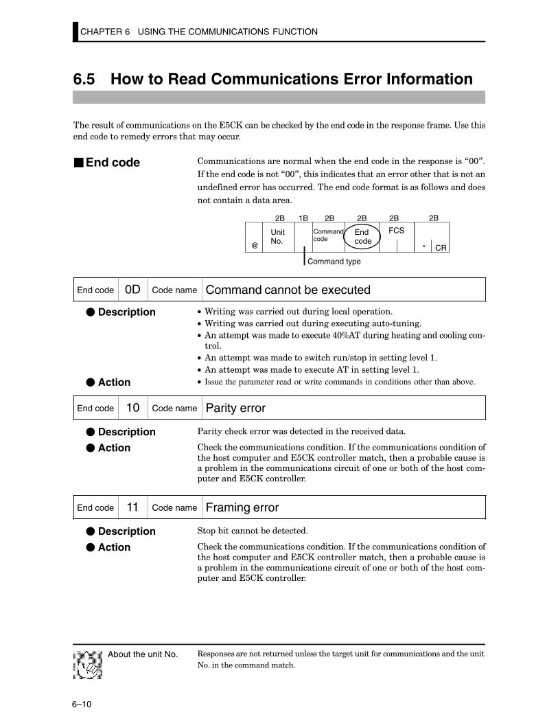
CHAPTER 6 USING THE COMMUNICATIONS FUNCTION
6–10
6.5 How to Read Communications Error Information
���������������������������������������&����������&������������������������ �����������"�������
������������������������������������
������������������������������������������������� �������7@@8�
*��������������������7@@8������������������������������������������������
���������������������������������������������������������������
����������������������
CR
UnitNo.
Commandcode
FCS
Command type
Endcode
@ *
2B2B 1B 2B 2B2B
End code 0D Code name Command cannot be executed
C• 9�������������������������������� �������
C• 9����������������������������1���������#������
C• )������� ��������������1�����,@D)����������������������������#
����
C• )������� ����������������������=�� ��������������.���:�
C• )������� ��������������1�����)���������������.���:�
C• Issue the parameter read or write commands in conditions other than above.
End code 10 Code name Parity error
$������������������������������������������.��������
�������������������������������*���������������������������
���������� ������������������������������������ �&�&������������ �&�������������������������������������&���������������#
����������������������
End code 11 Code name Framing error
�� �&���������&�����������
�������������������������������*���������������������������
���������� ������������������������������������ �&�&����������
�� �&�������������������������������������&���������������# ����������������������
3�� �������������������������������������������������������������������
+����������������������
About the unit No.
�End code
� Description
� Action
� Description
� Action
� Description
� Action
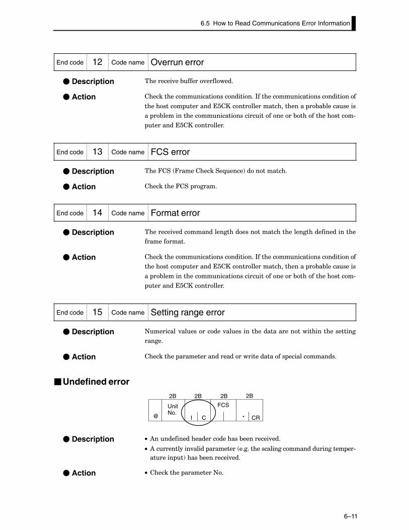
6.5 How to Read Communications Error Information
6–11
End code 12 Code name Overrun error
���������.��&�����.��������
�������������������������������*���������������������������
���������� ������������������������������������ �&�&����������
�� �&�������������������������������������&���������������#
����������������������
End code 13 Code name FCS error
����4��� 4�������������-����!������������
����������4��� ������
End code 14 Code name Format error
���������.�������������������������������������������������������
������������
�������������������������������*���������������������������
���������� ������������������������������������ �&�&����������
�� �&�������������������������������������&���������������#
����������������������
End code 15 Code name Setting range error
+��������.�����������.������������������������������������������
������
���������� ���������������������������������� ��������������
�Undefined error
CR
UnitNo.
FCS
@ *
2B2B 2B 2B
CI
C• )��������������������������&���������.���
C• )������������.����� ��������� ��������������������������������� ��#
������� �!�����&���������.���
C• ���������� ���������+�
� Description
� Action
� Description
� Action
� Description
� Action
� Description
� Action
� Description
� Action
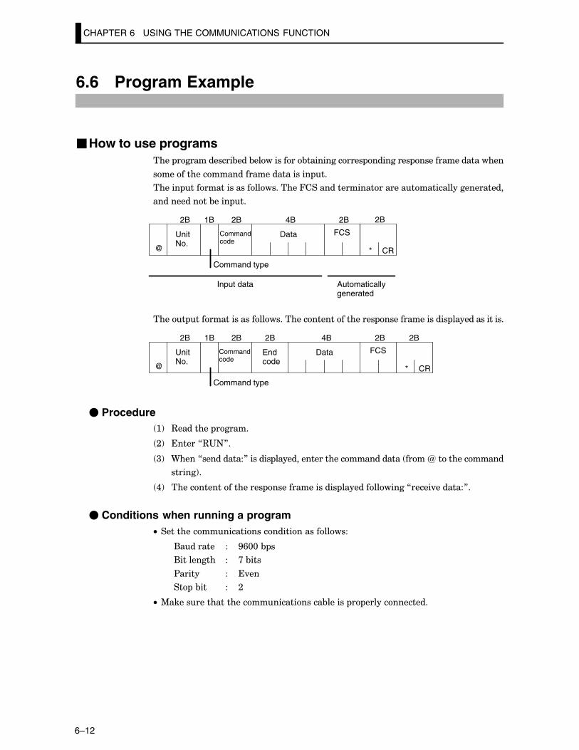
CHAPTER 6 USING THE COMMUNICATIONS FUNCTION
6–12
6.6 Program Example
�How to use programs���� ������������&���&����������&������������� ��������� �������������������
��������������������������������� ��
������ �������������������������4�������������������������������������������
������������&���� ��
CR
UnitNo.
Commandcode
Data FCS
Command type
@ *
2B2B 1B 2B 4B 2B
Input data Automaticallygenerated
����� ����������������������������������������� ���������������� ���������������
UnitNo.
Commandcode
Data FCS
Command type
CR
Endcode
@ *
2B 1B 2B 4B 2B 2B2B
� Procedure :! 3�������� ������
;! ������73"+8�
<! 9����7����������8������� ����������������������������� ����R�������������
������!�
,! �������������������� ���������������� ��������������7�����.�������8�
� Conditions when running a programC• �������������������������������������
(������� � G/@@�& �
(��������� � >�&���
$����� � �.��
�� �&�� � ;
C• %�������������������������������&������ � ��������������
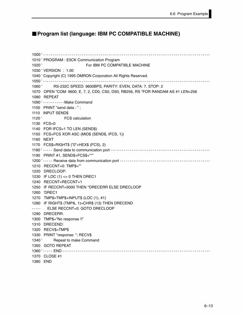
6.6 Program Example
6–13
�Program list (language: IBM PC COMPATIBLE MACHINE)
1000 ’1010 ’ PROGRAM : E5CK Communication Program1020 ’ For IBM PC COMPATIBLE MACHINE1030 ’ VERSION : 1.001040 ’ Copyright (C) 1995 OMRON Corporation All Rights Reserved.1050 ’1060 ’ RS-232C SPEED: 9600BPS, PARITY: EVEN, DATA: 7, STOP: 21070 OPEN ”COM: 9600, E, 7, 2, CD0, CS0, DS0, RB256, RS ”FOR RANDAM AS #1 LEN=2561080 REPEAT1090 ’ Make Command1100 PRINT ”send data : ” ;1110 INPUT SEND$1120 ’ FCS calculation1130 FCS=01140 FOR IFCS=1 TO LEN (SEND$)1150 FCS=FCS XOR ASC (MID$ (SEND$, IFCS, 1))1160 NEXT1170 FCS$=RIGHT$ (”0”+HEX$ (FCS), 2)1180 ’ Send data to communication port1190 PRINT #1, SEND$+FCS$+”*”1200 ’ Receive data from communication port1210 RECCNT=0: TMP$=””1220 DRECLOOP:1230 IF LOC (1) <> 0 THEN DREC11240 RECCNT=RECCNT+11250 IF RECCNT=5000 THEN *DRECERR ELSE DRECLOOP1260 ‘DREC11270 TMP$=TMP$+INPUT$ (LOC (1), #1)1280 IF RIGHT$ (TMP&, 1)=CHR$ (13) THEN DRECEND
ELSE RECCNT=0: GOTO DRECLOOP1290 DRECERR:1300 TMP$=”No response !!”1310 DRECEND:1320 RECV$=TMP$1330 PRINT ”response: ”; RECV$1340 ’ Repeat to make Command1350 GOTO REPEAT1360 ’ END1370 CLOSE #11380 END
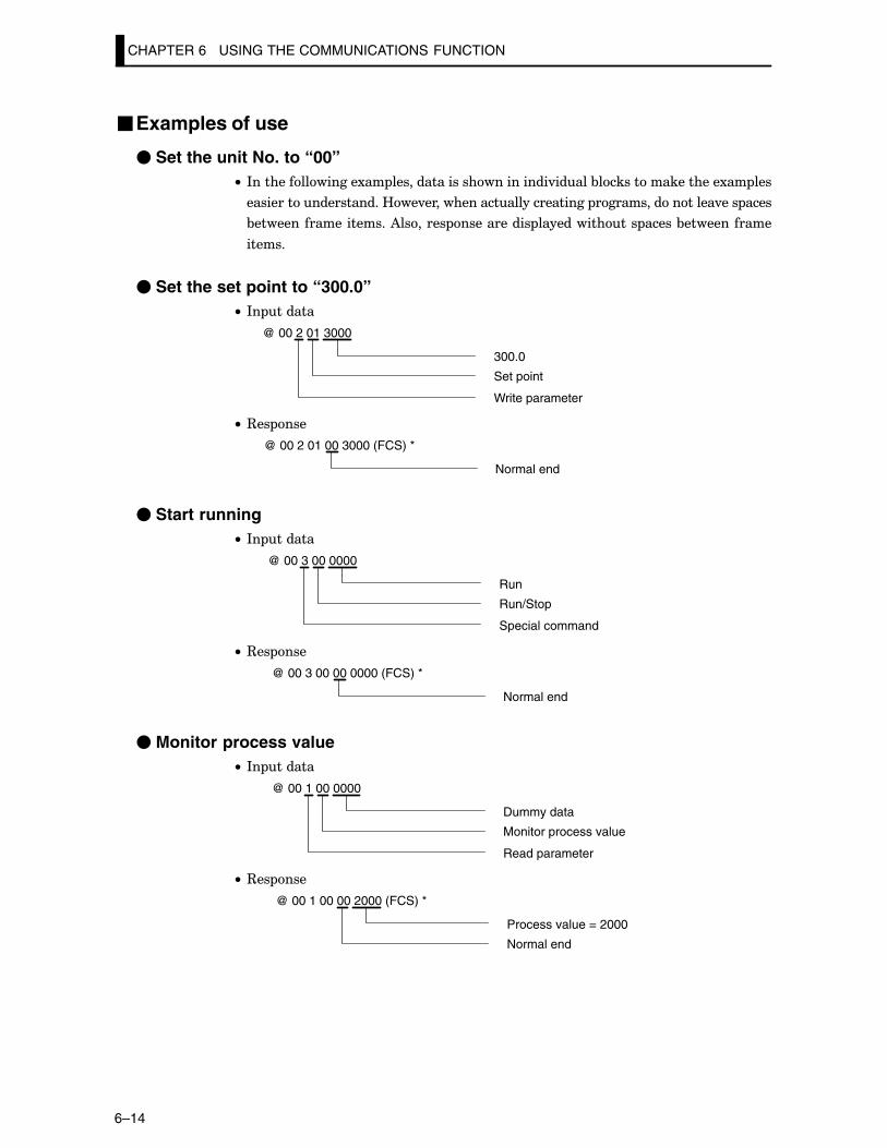
CHAPTER 6 USING THE COMMUNICATIONS FUNCTION
6–14
�Examples of use
� Set the unit No. to “00”C• *���������������1�� �������������������������.�����&�����������������1�� ���
��������������������B��.�������������������������� ����������������.��� ����
&��������������������)������� ����������� ������������� �����&������������
������
� Set the set point to “300.0”C• *� ������
@ 00 2 01 3000
300.0
Set point
Write parameter
C• 3�� ���
@ 00 2 01 00 3000 (FCS) *
Normal end
� Start runningC• *� ������
@ 00 3 00 0000
Run
Run/Stop
Special command
C• 3�� ���
@ 00 3 00 00 0000 (FCS) *
Normal end
� Monitor process valueC• *� ������
@ 00 1 00 0000
Dummy data
Monitor process value
Read parameter
C• 3�� ���
@ 00 1 00 00 2000 (FCS) *
Process value = 2000
Normal end
CHAPTER 7 TROUBLESHOOTING
7–1
CHAPTER 7TROUBLESHOOTING
�������� ����������&����������������������������������������������
�������������� � �����
CHAPTER7
>�: *������������� >F;����������������������������������������������������
>�; B����"������������?�� ��� >F<����������������������
>�< B����"��������2� � >F�������������������������������
>�, ���������2 �������3���������� >F/����������������
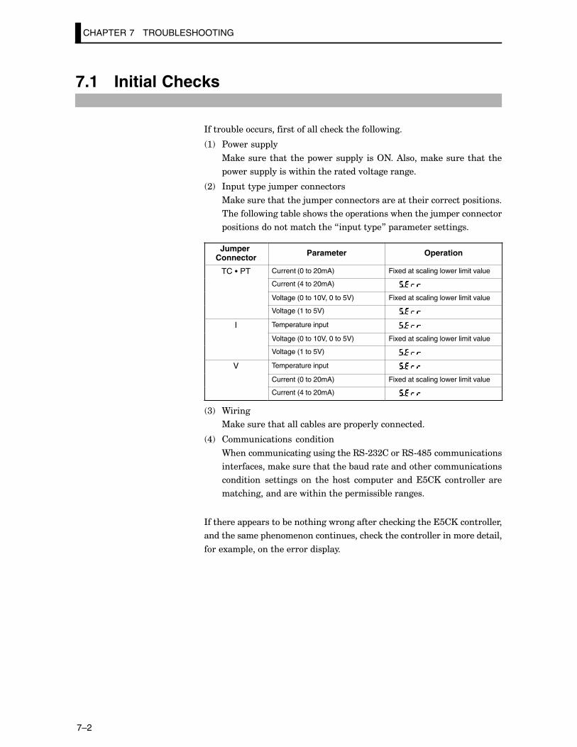
CHAPTER 7 TROUBLESHOOTING
7–2
7.1 Initial Checks
*����&���������������������������������������
:! $����� ��
%�������� ����� ���� ����� ��� ���2+��)���������������������
����� �����������������������.������������
;! *� ���� ��5� �����������
%�����������������5� �������������������������������� �������
��������������&������������ �����������������5� ����������
����������������������7�� ���� �8� ������������������
Jumper Connector Parameter Operation
TC � PT Current (0 to 20mA) Fixed at scaling lower limit value
Current (4 to 20mA)
Voltage (0 to 10V, 0 to 5V) Fixed at scaling lower limit value
Voltage (1 to 5V)
I Temperature input
Voltage (0 to 10V, 0 to 5V) Fixed at scaling lower limit value
Voltage (1 to 5V)
V Temperature input
Current (0 to 20mA) Fixed at scaling lower limit value
Current (4 to 20mA)
<! 9�����
%�������������������&�������� � ��������������
,! ������������ �������
9�������������������������3�#;<;����3�#,E�������������
������������������������������&����������������������������
�������� ��������� �� ���� ���� �� ���� ��������� ������������
����������������������������� �������&����������
*��������� �������&�����������������������������������������������
������������� ��������������������������������������������������
����1�� ������������������ ����
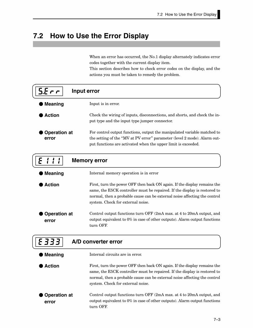
7.2 How to Use the Error Display
7–3
7.2 How to Use the Error Display
9����������������������������+�:���� ������������������������������
�������������������������������� ���������
������������������&��������������������������������� ������������
�������������&��������������������� �&����
Input error
*� �������������
��������������������� ���������������������������������������������#
���� ������������ ���� ��5� �����������
4��������� ������������ ���������� ������.����&������������
������������������7%A����$A�����8� ��������� ��.���;����!��)������#
������������������.�������������� �������������1�������
Memory error
*�������������� �����������������
4�������������� ����244������&����2+��������*��������� ���������������
����������������������������&���� �������*��������� ����������������
�������������� �&�&������������&���1�������������������������������
������������������1������������
������� ��������������244� ;�)���1�����,���;@�)�� ������
� ���-�.��������@D����������������� ��!��)������ ���������
����244�
A/D converter error
*����������������������������
4�������������� ����244������&����2+��������*��������� ���������������
����������������������������&���� �������*��������� ����������������
�������������� �&�&������������&���1�������������������������������
������������������1������������
������� ��������������244� ;�)���1�����,���;@�)�� ������
� ���-�.��������@D����������������� ��!��)������ ���������
����244�
� Meaning
� Action
� Operation aterror
� Meaning
� Action
� Operation aterror
� Meaning
� Action
� Operation aterror
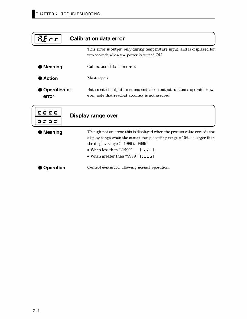
CHAPTER 7 TROUBLESHOOTING
7–4
Calibration data error
�������������� ��������������� ��������� ������������� ��������
������������������� �������������2+�
����&����������������������
%����� ����
(���������� ��������������������� ���������� �������B�#
�.����������������������������������������
Display range over
���������������������������� ��������������� ������.�����1���������
��� ������������������������������� ��������������T:@D!���������������
������� ���������� F:GGG���GGGG!�
C• 9��������������7#:GGG8 J K
C• 9�����������������7GGGG8 J K
����������������������������� �������
� Meaning
� Action
� Operation aterror
� Meaning
� Operation
7.3 How to Use Error Output
7–5
7.3 How to Use Error Output
����������������������������������������� ������������������#
���
4������������� �������������������<�<���������2� ��� �����������
����<#�!�
C• '()� ' �(�����)����!� ����&����������������� ������������� �
&���������������������� ��������������������������4��������������
����,#G�
C• '()������������������������������������
:!�B������&���
;!�2� ������� �������������������������������������!
<!������������ ���������� ��.����������!
C• *�����������'()������������������ �&��������������������������
�� �������������������������� �������7'()��������������8� ��������
��.���;����!�
C• *����������������:��������� ���������������&��� ��������� �
������������9���������������������������&�������������������� ���
���7*� ������8� ����>#<!�
C• *����������������;��������� ���������������&��� �����������)=?
��.������������������9���������������������������&�������������
������ �������7)=?���.����������8� ����>#<!�
� LBA
� Input errors
� A/D convertererror
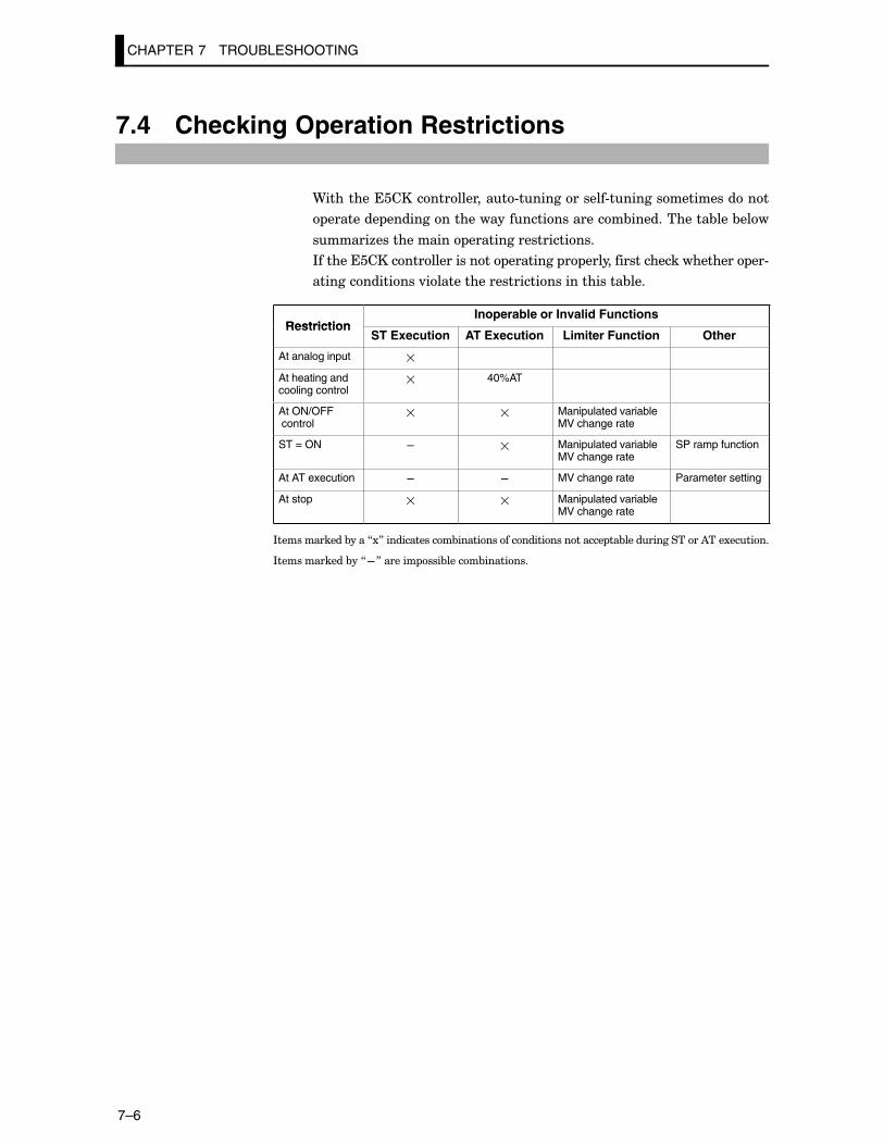
CHAPTER 7 TROUBLESHOOTING
7–6
7.4 Checking Operation Restrictions
9�������������������������#������������#�������������������
�������� �������������������������������&������������&���&���
������6������������ ��������������������
*�������������������������� �������� � �������������������������� ��#
���������������.��������������������������������&���
RestrictionInoperable or Invalid Functions
RestrictionST Execution AT Execution Limiter Function Other
At analog input �
At heating andcooling control
� 40%AT
At ON/OFF control
� � Manipulated variableMV change rate
ST = ON – � Manipulated variableMV change rate
SP ramp function
At AT execution – – MV change rate Parameter setting
At stop � � Manipulated variableMV change rate
*������������&����718�������������&�������������������������� ��&��������������)���1������
*������������&��7F8������� ���&�����&��������
APPENDIX
A–1
APPENDIX
�$��*4*�)�*2+� )F;��������������������������������������������������
�2+�32'�('2���?*)Q3)% )F�����������������������������
����*+Q�'*�� )F/��������������������������������������������������������
$)3)%���3�2$�3)�*2+��'*�� )FE��������������������
4"UUI���'4#�"+*+Q )F:@������������������������������������������
%2?�'�'*�� )F:<������������������������������������������������������������
O�423%)� )F:,����������������������������������������������������������������
)��**��2?��'*�� )F:>����������������������������������������������������
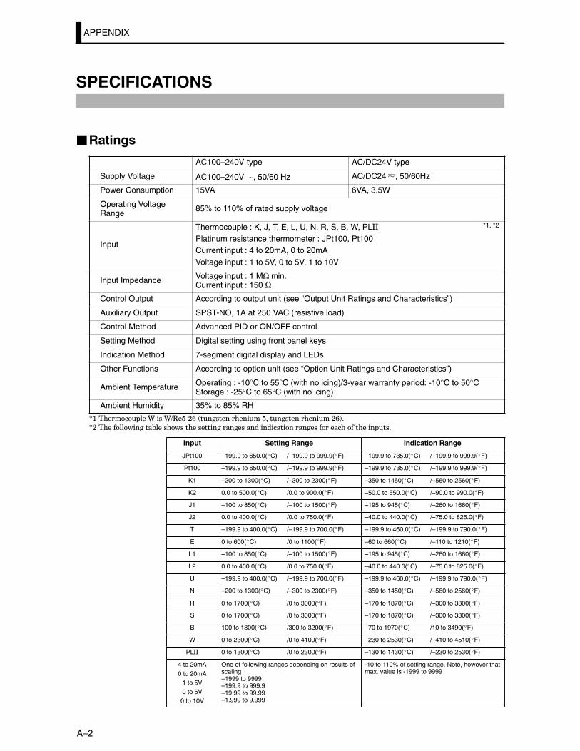
APPENDIX
A–2
SPECIFICATIONS
�Ratings
AC100–240V type AC/DC24V type
Supply Voltage AC100–240V , 50/60 Hz~ AC/DC24 , 50/60Hz
Power Consumption 15VA 6VA, 3.5W
Operating VoltageRange
85% to 110% of rated supply voltage
Input
Thermocouple : K, J, T, E, L, U, N, R, S, B, W, PL**
Platinum resistance thermometer : JPt100, Pt100Current input : 4 to 20mA, 0 to 20mAVoltage input : 1 to 5V, 0 to 5V, 1 to 10V
Input Impedance Voltage input : 1 MΩ min.Current input : 150 Ω
Control Output According to output unit (see “Output Unit Ratings and Characteristics”)
Auxiliary Output SPST-NO, 1A at 250 VAC (resistive load)
Control Method Advanced PID or ON/OFF control
Setting Method Digital setting using front panel keys
Indication Method 7-segment digital display and LEDs
Other Functions According to option unit (see “Option Unit Ratings and Characteristics”)
Ambient Temperature Operating : -10°C to 55°C (with no icing)/3-year warranty period: -10°C to 50°CStorage : -25°C to 65°C (with no icing)
Ambient Humidity 35% to 85% RH
S:������� ���9����9=3��#;/� ���������������������������������;/!�
S;���������������&���������������������������������������������������������������� ���
Input Setting Range Indication Range
JPt100 –199.9 to 650.0(�C) /–199.9 to 999.9(�F) –199.9 to 735.0(�C) /–199.9 to 999.9(�F)
Pt100 –199.9 to 650.0(�C) /–199.9 to 999.9(�F) –199.9 to 735.0(�C) /–199.9 to 999.9(�F)
K1 –200 to 1300(�C) /–300 to 2300(�F) –350 to 1450(�C) /–560 to 2560(�F)
K2 0.0 to 500.0(�C) /0.0 to 900.0(�F) –50.0 to 550.0(�C) /–90.0 to 990.0(�F)
J1 –100 to 850(�C) /–100 to 1500(�F) –195 to 945(�C) /–260 to 1660(�F)
J2 0.0 to 400.0(�C) /0.0 to 750.0(�F) –40.0 to 440.0(�C) /–75.0 to 825.0(�F)
T –199.9 to 400.0(�C) /–199.9 to 700.0(�F) –199.9 to 460.0(�C) /–199.9 to 790.0(�F)
E 0 to 600(�C) /0 to 1100(�F) –60 to 660(�C) /–110 to 1210(�F)
L1 –100 to 850(�C) /–100 to 1500(�F) –195 to 945(�C) /–260 to 1660(�F)
L2 0.0 to 400.0(�C) /0.0 to 750.0(�F) –40.0 to 440.0(�C) /–75.0 to 825.0(�F)
U –199.9 to 400.0(�C) /–199.9 to 700.0(�F) –199.9 to 460.0(�C) /–199.9 to 790.0(�F)
N –200 to 1300(�C) /–300 to 2300(�F) –350 to 1450(�C) /–560 to 2560(�F)
R 0 to 1700(�C) /0 to 3000(�F) –170 to 1870(�C) /–300 to 3300(�F)
S 0 to 1700(�C) /0 to 3000(�F) –170 to 1870(�C) /–300 to 3300(�F)
B 100 to 1800(�C) /300 to 3200(�F) –70 to 1970(�C) /10 to 3490(�F)
W 0 to 2300(�C) /0 to 4100(�F) –230 to 2530(�C) /–410 to 4510(�F)
PL** 0 to 1300(�C) /0 to 2300(�F) –130 to 1430(�C) /–230 to 2530(�F)
4 to 20mA0 to 20mA
1 to 5V0 to 5V0 to 10V
One of following ranges depending on results ofscaling–1999 to 9999–199.9 to 999.9–19.99 to 99.99–1.999 to 9.999
-10 to 110% of setting range. Note, however thatmax. value is -1999 to 9999
*1, *2
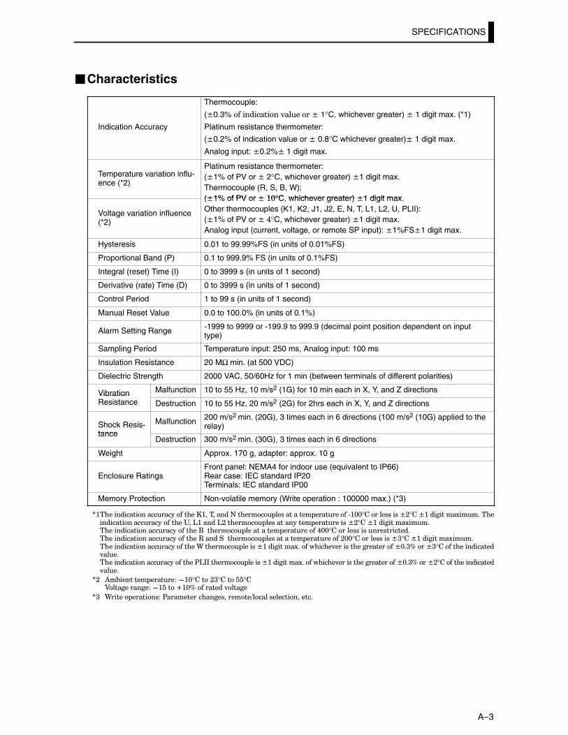
SPECIFICATIONS
A–3
�Characteristics
Indication Accuracy
Thermocouple:
(T0.3% ������������.������T 1°C, whichever greater) T 1 digit max. (*1)
Platinum resistance thermometer:
(T0.2% of indication value or T 0.8°C whichever greater)T 1 digit max.
Analog input: T0.2%T 1 digit max.
Temperature variation influ-ence (*2)
Platinum resistance thermometer:(T1% of PV or T 2°C, whichever greater) T1 digit max.Thermocouple (R, S, B, W):(T1% of PV or T :@°C whichever greater) T1 digit max
Voltage variation influence(*2)
(T1% of PV or T�:@°C, whichever greater) T1 digit max.Other thermocouples (K1, K2, J1, J2, E, N, T, L1, L2, U, PLII):(T1% of PV or T�,°C, whichever greater) T1 digit max.Analog input (current, voltage, or remote SP input): T1%FST1 digit max.
Hysteresis 0.01 to 99.99%FS (in units of 0.01%FS)
Proportional Band (P) 0.1 to 999.9% FS (in units of 0.1%FS)
Integral (reset) Time (I) 0 to 3999 s (in units of 1 second)
Derivative (rate) Time (D) 0 to 3999 s (in units of 1 second)
Control Period 1 to 99 s (in units of 1 second)
Manual Reset Value 0.0 to 100.0% (in units of 0.1%)
Alarm Setting Range -1999 to 9999 or -199.9 to 999.9 (decimal point position dependent on inputtype)
Sampling Period Temperature input: 250 ms, Analog input: 100 ms
Insulation Resistance 20 MΩ min. (at 500 VDC)
Dielectric Strength 2000 VAC, 50/60Hz for 1 min (between terminals of different polarities)
Vibration Malfunction 10 to 55 Hz, 10 m/s2 (1G) for 10 min each in X, Y, and Z directionsVibrationResistance Destruction 10 to 55 Hz, 20 m/s2 (2G) for 2hrs each in X, Y, and Z directions
Shock Resis-tance
Malfunction 200 m/s2 min. (20G), 3 times each in 6 directions (100 m/s2 (10G) applied to therelay)
tanceDestruction 300 m/s2 min. (30G), 3 times each in 6 directions
Weight Approx. 170 g, adapter: approx. 10 g
Enclosure RatingsFront panel: NEMA4 for indoor use (equivalent to IP66)Rear case: IEC standard IP20Terminals: IEC standard IP00
Memory Protection Non-volatile memory (Write operation : 100000 max.) (*3)
S:�����������������������������:���������+������� ������������ ���������#:@@°������������T;°��T:���������1��������������������������������"��':�����';������� �������������� ����������T;°��T:���������1��������������������������������(�������� ����������� ���������,@@°����������������������������������������������������3�������������� ������������ ���������;@@°������������T<°��T:���������1��������������������������������9������� ������T:���������1����������.��������������������T@�<D���T<°�����������������.��������������������������������$'**������� ������T:���������1����������.��������������������T@�<D���T;°�����������������.����
S; )�&�������� ��������F:@°����;<°������°�A�������������F:����V:@D���������.�����
S< 9����� ���������$�����������������������=�������������������
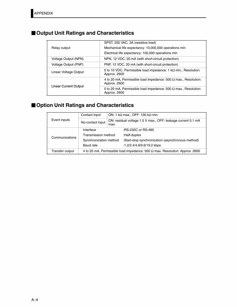
APPENDIX
A–4
�Output Unit Ratings and Characteristics
Relay output
SPST, 250 VAC, 3A (resistive load)
Mechanical life expectancy: 10,000,000 operations min
Electrical life expectancy: 100,000 operations min
Voltage Output (NPN) NPN, 12 VDC, 20 mA (with short-circuit protection)
Voltage Output (PNP) PNP, 12 VDC, 20 mA (with short-circuit protection)
Linear Voltage Output 0 to 10 VDC, Permissible load impedance: 1 kΩ min., Resolution:Approx. 2600
Linear Current Output
4 to 20 mA, Permissible load impedance: 500 Ω max., Resolution:Approx. 2600
Linear Current Output0 to 20 mA, Permissible load impedance: 500 Ω max., Resolution:Approx. 2600
�Option Unit Ratings and Characteristics
Contact input ON: 1 kΩ max., OFF: 100 kΩ min.
Event inputsNo-contact input ON: residual voltage 1.5 V max., OFF: leakage current 0.1 mA
max.
Communications
Interface :RS-232C or RS-485
Transmission method :Half-duplex
Synchronization method :Start-stop synchronization (asynchronous method)
Baud rate :1.2/2.4/4.8/9.6/19.2 kbps
Transfer output 4 to 20 mA, Permissible load impedance: 500 Ω max. Resolution: Approx. 2600
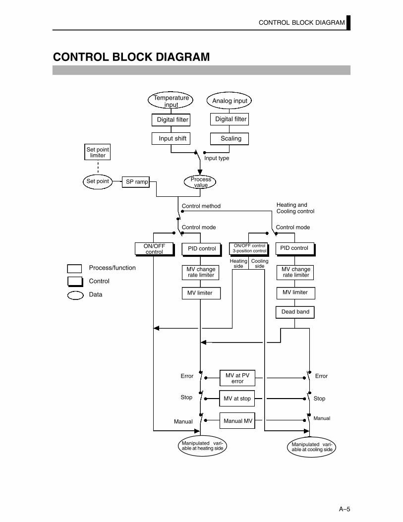
CONTROL BLOCK DIAGRAM
A–5
CONTROL BLOCK DIAGRAM
Temperatureinput
Digital filter
Input shift
Analog input
Digital filter
Scaling
Input type
Control method
Control mode
ON/OFFcontrol
PID controlON/OFF control3-position control PID control
Control mode
Process/function
Control
Data
MV changerate limiter
MV limiter
Heatingside
Coolingside
MV changerate limiter
MV limiter
Dead band
Error
Stop
Manual
MV at PVerror
MV at stop
Manual MV
Error
Stop
Manual
Manipulated vari-able at heating side
Manipulated vari-able at cooling side
Set pointlimiter
Processvalue
Set point SP ramp
Heating and Cooling control
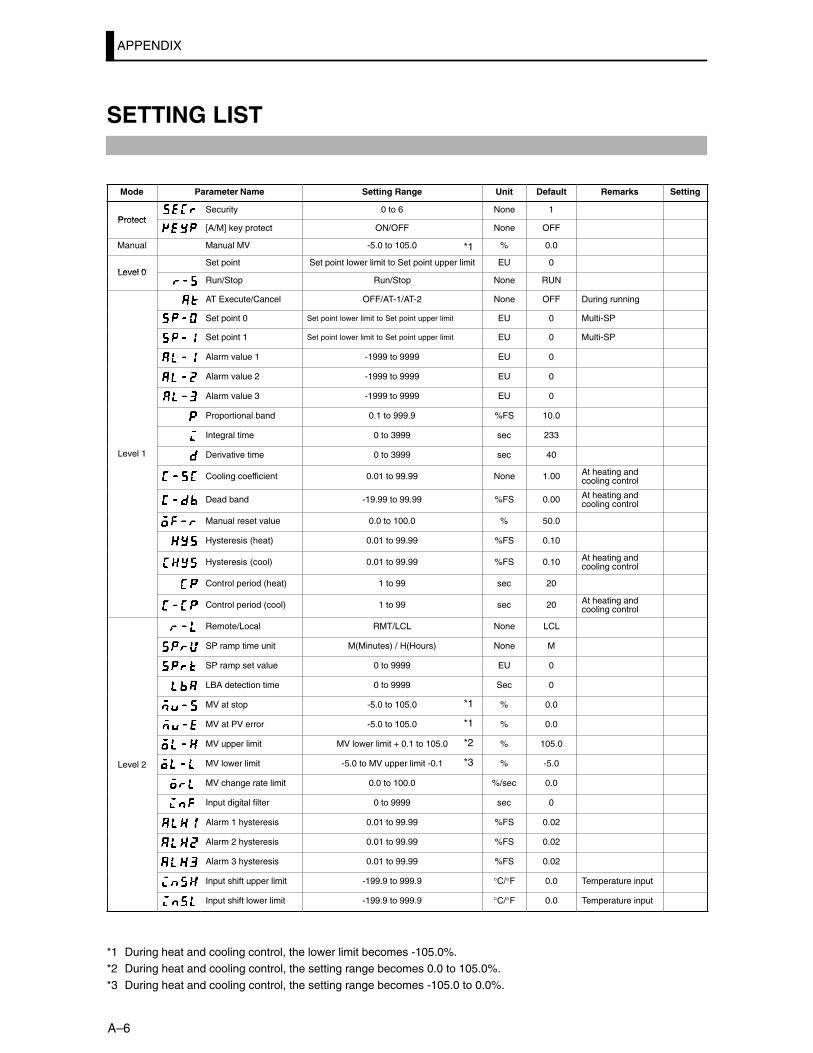
APPENDIX
A–6
SETTING LIST
Mode Parameter Name Setting Range Unit Default Remarks Setting
ProtectSecurity 0 to 6 None 1
Protect[A/M] key protect ON/OFF None OFF
Manual Manual MV -5.0 to 105.0 % 0.0
Level 0Set point Set point lower limit to Set point upper limit EU 0
Level 0Run/Stop Run/Stop None RUN
AT Execute/Cancel OFF/AT-1/AT-2 None OFF During running
Set point 0 Set point lower limit to Set point upper limit EU 0 Multi-SP
Set point 1 Set point lower limit to Set point upper limit EU 0 Multi-SP
Alarm value 1 -1999 to 9999 EU 0
Alarm value 2 -1999 to 9999 EU 0
Alarm value 3 -1999 to 9999 EU 0
Proportional band 0.1 to 999.9 %FS 10.0
Integral time 0 to 3999 sec 233
Level 1 Derivative time 0 to 3999 sec 40
Cooling coefficient 0.01 to 99.99 None 1.00 At heating andcooling control
Dead band -19.99 to 99.99 %FS 0.00 At heating andcooling control
Manual reset value 0.0 to 100.0 % 50.0
Hysteresis (heat) 0.01 to 99.99 %FS 0.10
Hysteresis (cool) 0.01 to 99.99 %FS 0.10 At heating andcooling control
Control period (heat) 1 to 99 sec 20
Control period (cool) 1 to 99 sec 20 At heating andcooling control
Remote/Local RMT/LCL None LCL
SP ramp time unit M(Minutes) / H(Hours) None M
SP ramp set value 0 to 9999 EU 0
LBA detection time 0 to 9999 Sec 0
MV at stop -5.0 to 105.0 % 0.0
MV at PV error -5.0 to 105.0 % 0.0
MV upper limit MV lower limit + 0.1 to 105.0 % 105.0
Level 2 MV lower limit -5.0 to MV upper limit -0.1 % -5.0
MV change rate limit 0.0 to 100.0 %/sec 0.0
Input digital filter 0 to 9999 sec 0
Alarm 1 hysteresis 0.01 to 99.99 %FS 0.02
Alarm 2 hysteresis 0.01 to 99.99 %FS 0.02
Alarm 3 hysteresis 0.01 to 99.99 %FS 0.02
Input shift upper limit -199.9 to 999.9 °C/°F 0.0 Temperature input
Input shift lower limit -199.9 to 999.9 °C/°F 0.0 Temperature input
*1 During heat and cooling control, the lower limit becomes -105.0%.*2 During heat and cooling control, the setting range becomes 0.0 to 105.0%.*3 During heat and cooling control, the setting range becomes -105.0 to 0.0%.
*1
*1
*1
*2
*3
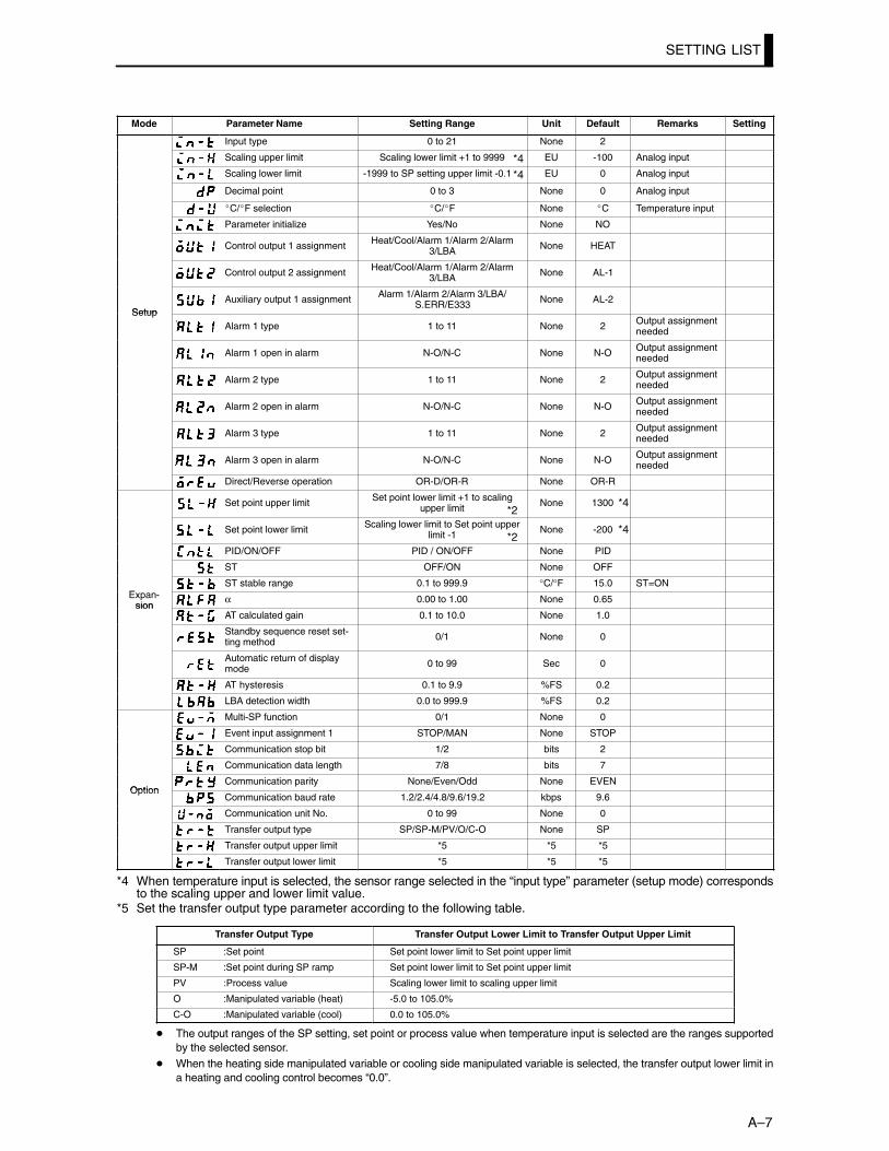
SETTING LIST
A–7
Mode Parameter Name Setting Range Unit Default Remarks Setting
Input type 0 to 21 None 2
Scaling upper limit Scaling lower limit +1 to 9999 EU -100 Analog input
Scaling lower limit -1999 to SP setting upper limit -0.1 EU 0 Analog input
Decimal point 0 to 3 None 0 Analog input
�C/�F selection �C/�F None �C Temperature input
Parameter initialize Yes/No None NO
Control output 1 assignment Heat/Cool/Alarm 1/Alarm 2/Alarm3/LBA None HEAT
Control output 2 assignment Heat/Cool/Alarm 1/Alarm 2/Alarm3/LBA None AL-1
SetupAuxiliary output 1 assignment Alarm 1/Alarm 2/Alarm 3/LBA/
S.ERR/E333 None AL-2Setup
Alarm 1 type 1 to 11 None 2 Output assignmentneeded
Alarm 1 open in alarm N-O/N-C None N-O Output assignmentneeded
Alarm 2 type 1 to 11 None 2 Output assignmentneeded
Alarm 2 open in alarm N-O/N-C None N-O Output assignmentneeded
Alarm 3 type 1 to 11 None 2 Output assignmentneeded
Alarm 3 open in alarm N-O/N-C None N-O Output assignmentneeded
Direct/Reverse operation OR-D/OR-R None OR-R
Set point upper limit Set point lower limit +1 to scalingupper limit None 1300
Set point lower limit Scaling lower limit to Set point upperlimit -1 None -200
PID/ON/OFF PID / ON/OFF None PID
ST OFF/ON None OFF
EST stable range 0.1 to 999.9 °C/°F 15.0 ST=ON
Expan-sion
α 0.00 to 1.00 None 0.65sion
AT calculated gain 0.1 to 10.0 None 1.0
Standby sequence reset set-ting method 0/1 None 0
Automatic return of displaymode 0 to 99 Sec 0
AT hysteresis 0.1 to 9.9 %FS 0.2
LBA detection width 0.0 to 999.9 %FS 0.2
Multi-SP function 0/1 None 0
Event input assignment 1 STOP/MAN None STOP
Communication stop bit 1/2 bits 2
Communication data length 7/8 bits 7
OptionCommunication parity None/Even/Odd None EVEN
OptionCommunication baud rate 1.2/2.4/4.8/9.6/19.2 kbps 9.6
Communication unit No. 0 to 99 None 0
Transfer output type SP/SP-M/PV/O/C-O None SP
Transfer output upper limit *5 *5 *5
Transfer output lower limit *5 *5 *5
*4 When temperature input is selected, the sensor range selected in the “input type” parameter (setup mode) correspondsto the scaling upper and lower limit value.
*5 Set the transfer output type parameter according to the following table.
Transfer Output Type Transfer Output Lower Limit to Transfer Output Upper Limit
SP :Set point Set point lower limit to Set point upper limit
SP-M :Set point during SP ramp Set point lower limit to Set point upper limit
PV :Process value Scaling lower limit to scaling upper limit
O :Manipulated variable (heat) -5.0 to 105.0%
C-O :Manipulated variable (cool) 0.0 to 105.0%
� The output ranges of the SP setting, set point or process value when temperature input is selected are the ranges supportedby the selected sensor.
� When the heating side manipulated variable or cooling side manipulated variable is selected, the transfer output lower limit ina heating and cooling control becomes “0.0”.
*4*4
*4*2
*2*4
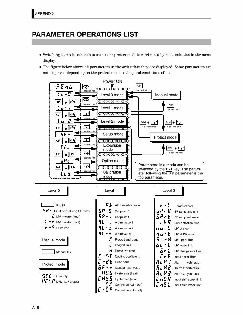
APPENDIX
A–8
PARAMETER OPERATIONS LIST
C• ����������������������������������� �����������������������&�������������������������
��� ����
C• ����������&������������� ��������������������������������������� ����������� �������������
������ �������� ������������� ������������������������������������
A/M
A/M
A/MA/M
A/M
+ +
+
1 second min.
Level 0 mode
Level 1 mode
Level 2 mode
Setup mode
Expansionmode
Option mode
Calibrationmode
1 second min.
Manual mode
Protect mode
1 second min.
1 second min. 1 second min.
1 second min.
Parameters in a mode can beswitched by the key. The param-eter following the last parameter is thetop parameter.
Level 0
PV/SP
Set point during SP ramp
MV monitor (heat)
MV monitor (cool)
Run/Stop
Manual MV
Security
[A/M] key protect
Manual mode
Protect mode
AT Execute/Cancel
Set point 0
Set point 1
Alarm value 1
Alarm value 2
Alarm value 3
Proportional band
Integral time
Derivative time
Cooling coefficient
Dead band
Manual reset value
Hysteresis (heat)
Hysteresis (cool)
Control period (heat)
Control period (cool)
Level 1
Remote/Local
SP ramp time unit
SP ramp set value
LBA detection time
MV at stop
MV at PV error
MV upper limit
MV lower limit
MV change rate limit
Input digital filter
Alarm 1 hysteresis
Alarm 2 hysteresis
Alarm 3 hysteresis
Input shift upper limit
Input shift lower limit
Level 2
1 second min.
Power ON
1 second min.
1 second min.
1 second min.
1 second min.
1 second min.
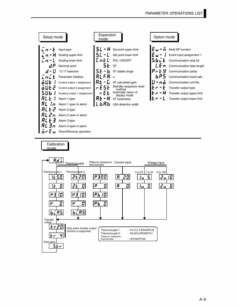
PARAMETER OPERATIONS LIST
A–9
Input type
Scaling upper limit
Scaling lower limit
Decimal point
�C/�F selection
Parameter initialize
Control output 1 assignment
Control output 2 assignment
Auxiliary output 1 assignment
Alarm 1 type
Alarm 1 open in alarm
Alarm 2 type
Alarm 2 open in alarm
Alarm 3 type
Alarm 3 open in alarm
Direct/Reverse operation
Setup mode
Set point upper limit
Set point lower limit
PID / ON/OFF
ST
ST stable range
α
AT calculated gainStandby sequence reset
methodAutomatic return of
display modeAT hysteresis
LBA detection width
Expansionmode
Multi-SP function
Event input assignment 1
Communication stop bit
Communication data length
Communication parity
Communication baud rate
Communication unit No.
Transfer output type
Transfer output upper limit
Transfer output lower limit
Option mode
Calibrationmode
Thermocouple Platinum resistancethermometer
Current input Voltage input
Thermocouple 1 Thermocouple 2
Transfer output
Data save
0 to 5V 1 to 5V 0 to 10V
Only when transfer outputfunction is supported Thermocouple 1 : K1/J1/L1/E/N/W/PL**
Thermocouple 2 : K2/J2/L2/R/S/B/T/UPlatinum resistance thermometer : JPt100/Pt100
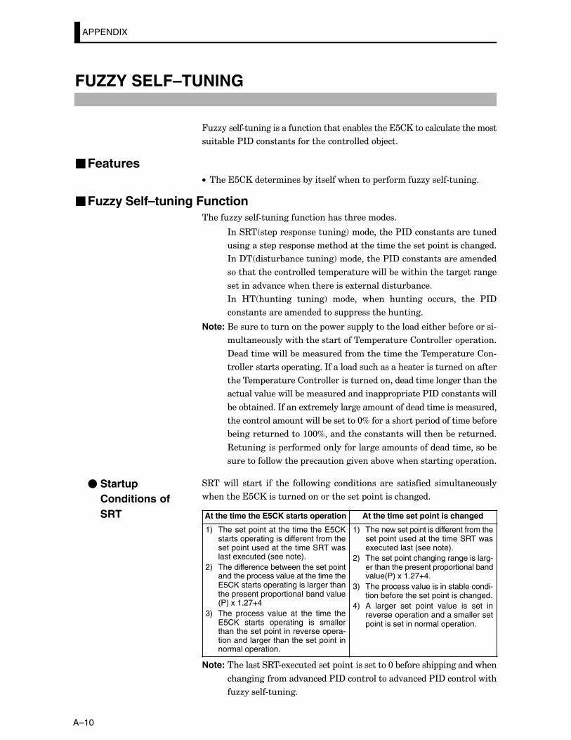
APPENDIX
A–10
FUZZY SELF–TUNING
466������#��������������������������&�������������������������������
����&���$*?��������������������������&5����
�FeaturesC• ��������������������&���������������� �������66������#������
�Fuzzy Self–tuning Function�����66������#����������������������������
*���3� ��� ���� ���������!����������$*?������������������
���������� ���� ������������������������������ ���������������
*��?� �����&����������!����������$*?���������������������
����������������������� ������������&�������������������������
���������.��������������������1������������&�����
*�� B� ������� �����!� ����� ����� ������� ������ ���� $*?
������������������������ ����������������
Note: (������������������ ����� ��������������������&���������#
������������������������������ ���������������� �������
?��������������&������������������������������ ���������#
�������������� ���������*����������������������������������������
������� ����������������������������������������������������
������.���������&����������������� � ������$*?��������������
&��&��������*������1������������������������������������������
��������������������&��������@D����������� ������������&����
&���������������:@@D�����������������������������&����������
3���������� ������������������������������������������&�
��������������� ����������.����&.���������������� �������
�3������� ������ ��� ���� �������� ��������� ���� ���������� �����������
����������������������������������� ���������������
At the time the E5CK starts operation At the time set point is changed
1) The set point at the time the E5CKstarts operating is different from theset point used at the time SRT waslast executed (see note).
2) The difference between the set pointand the process value at the time theE5CK starts operating is larger thanthe present proportional band value(P) x 1.27+4
3) The process value at the time theE5CK starts operating is smallerthan the set point in reverse opera-tion and larger than the set point innormal operation.
1) The new set point is different from theset point used at the time SRT wasexecuted last (see note).
2) The set point changing range is larg-er than the present proportional bandvalue(P) x 1.27+4.
3) The process value is in stable condi-tion before the set point is changed.
4) A larger set point value is set inreverse operation and a smaller setpoint is set in normal operation.
Note: ����������3�#�1���������� �������������@�&�������� ������������
���������������.������$*?�����������.������$*?�����������
�66������#������
� Startup Conditions of SRT
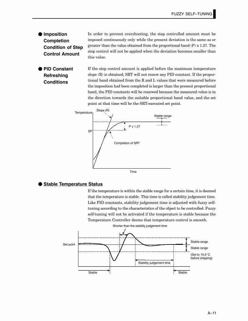
FUZZY SELF–TUNING
A–11
*������� �� ��.����.���������� ���� ��� � ������������������&�
�� ��������������������������� ���������.����������������������
�����������������.����&��������������� � �������&���� $!�1�:�;>�����
��� ���������������&��� ����������������.������&������������������
�����.����
*��������� ���������������� �����&�����������1������� ������
�� �� 3!����&���������3��������������������$*?����������*������ � �#
������&����&���������������3�����'�.�����������������������&����
������ ����������&������ ������������������������� ������� � ������
&���������$*?���������������&����������&������������������.���������
����������������������������&��� � �������&����.����������������
����������������������&�������3�#�1���������� ����
TemperatureSlope (R)
SP
Stable range
P x 1.27
Completion of SRT
Time
� Stable Temperature Status*��������� ������������������������&����������������������������������������
������������ �������������&���������������������������&������5�������������
'����$*?��������������&������5������������������5�����������66������#
�������������������������������������������&5������&������������466�
����#��������������&������.��������������� �������������&���&���������
��� ������������������������������ ���������������������
Stable
Stable range
Stable range
Stable
Stability judgement time
Set point
Shorter than the stability judgement time
(Set to 15.0�Cbefore shipping)
� ImpositionCompletionCondition of StepControl Amount
� PID Constant RefreshingConditions
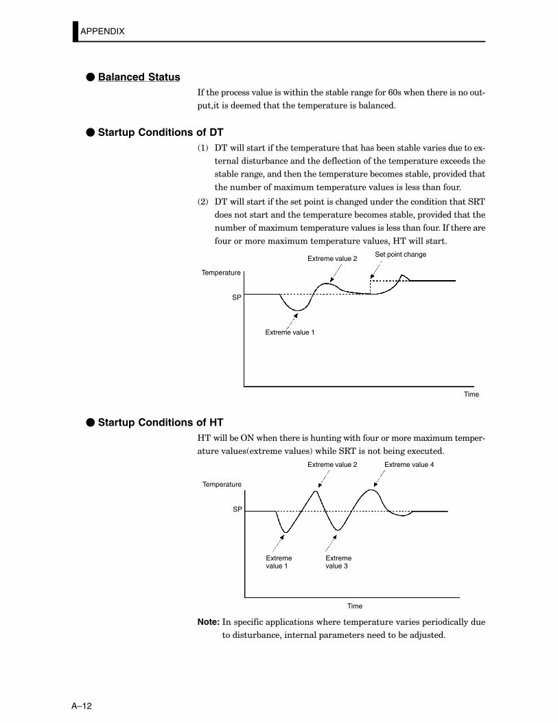
APPENDIX
A–12
� Balanced Status*������ ������.���������������������&������������/@�������������������#
��������������������������� ����������&��������
� Startup Conditions of DT :! ?����������������������� ����������������&�������&���.������������1#
������������&�������������������������������� ��������1���������
���&�������������������������� �������&���������&���� �.���������
������&�������1������� �������.���������������������
;! ?������������������������ ��������������������������������������3�
������������������������ �������&���������&���� �.�������������
��&�������1������� �������.����������������������*�����������
�����������1������� �������.������B�������������
Temperature
Extreme value 2
SP
Set point change
Extreme value 1
Time
� Startup Conditions of HTB�������&��2+��������������������������������������1������� ��#
�����.���� �1������.����!��������3��������&������1������
Temperature
Extreme value 2
SP
Extreme value 4
Extremevalue 1
Time
Extremevalue 3
Note: *��� �������� ������������������ �������.������ �������������
�������&��������������� �����������������&����5�����
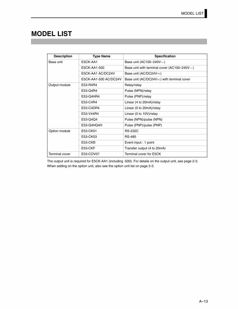
MODEL LIST
A–13
MODEL LIST
Description Type Name Specification
Base unit E5CK-AA1 Base unit (AC100–240V )
E5CK-AA1-500 Base unit with terminal cover (AC100–240V )
E5CK-AA1 AC/DC24V Base unit (AC/DC24V )
E5CK-AA1-500 AC/DC24V Base unit (AC/DC24V ) with terminal cover
Output module E53-R4R4 Relay/relay
E53-Q4R4 Pulse (NPN)/relay
E53-Q4HR4 Pulse (PNP)/relay
E53-C4R4 Linear (4 to 20mA)/relay
E53-C4DR4 Linear (0 to 20mA)/relay
E53-V44R4 Linear (0 to 10V)/relay
E53-Q4Q4 Pulse (NPN)/pulse (NPN)
E53-Q4HQ4H Pulse (PNP)/pulse (PNP)
Option module E53-CK01 RS-232C
E53-CK03 RS-485
E53-CKB Event input : 1 point
E53-CKF Transfer output (4 to 20mA)
Terminal cover E53-COV07 Terminal cover for E5CK
The output unit is required for E5CK-AA1 (including -500). For details on the output unit, see page 2-3.When adding on the option unit, also see the option unit list on page 2-3.
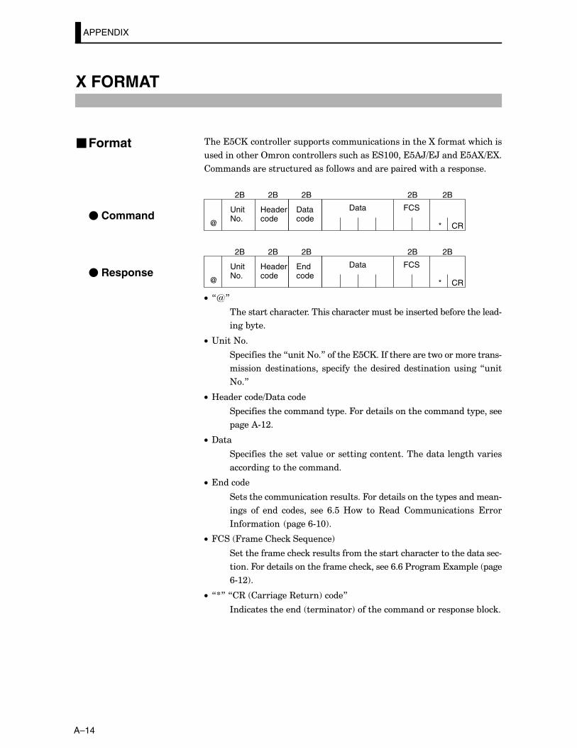
APPENDIX
A–14
X FORMAT
������������������� �����������������������O���������������
������������2�����������������������:@@����)H=�H�������)O=�O�
�������������������������������������� ���������������� ����
Headercode
UnitNo.
FCS
CR@ *
2B 2B 2B 2B
Datacode
2B
Data
Headercode
UnitNo.
FCS
CR@ *
2B 2B 2B 2B
Endcode
2B
Data
C• 7R8
����������������������������������������&�����������&�������������#
����&����
C• "����+�
� ������������7����+�8�������������*��������������������������#
�������������������� � ������ ����������������������������7���
+�8
C• B���������=?�������
� ��������������������� ���4������������������������� ������
����)#:;�
C• ?���
� ����������������.��������������������������������������.�����
����������������������
C• �������
����������������������������4������������������ �����������#
����� �� ���� ������ ���� /���B�� �� 3���� ������������ ����
*��������� ����/#:@!�
C• 4��� 4�������������-����!
�����������������������������������������������������������������#
�����4���������������������������������/�/�$�������1�� ��� ���
/#:;!�
C• 7S8�7�3� ���������3����!����8
*����������������� ���������!������������������� ����&����
�Format
� Command
� Response
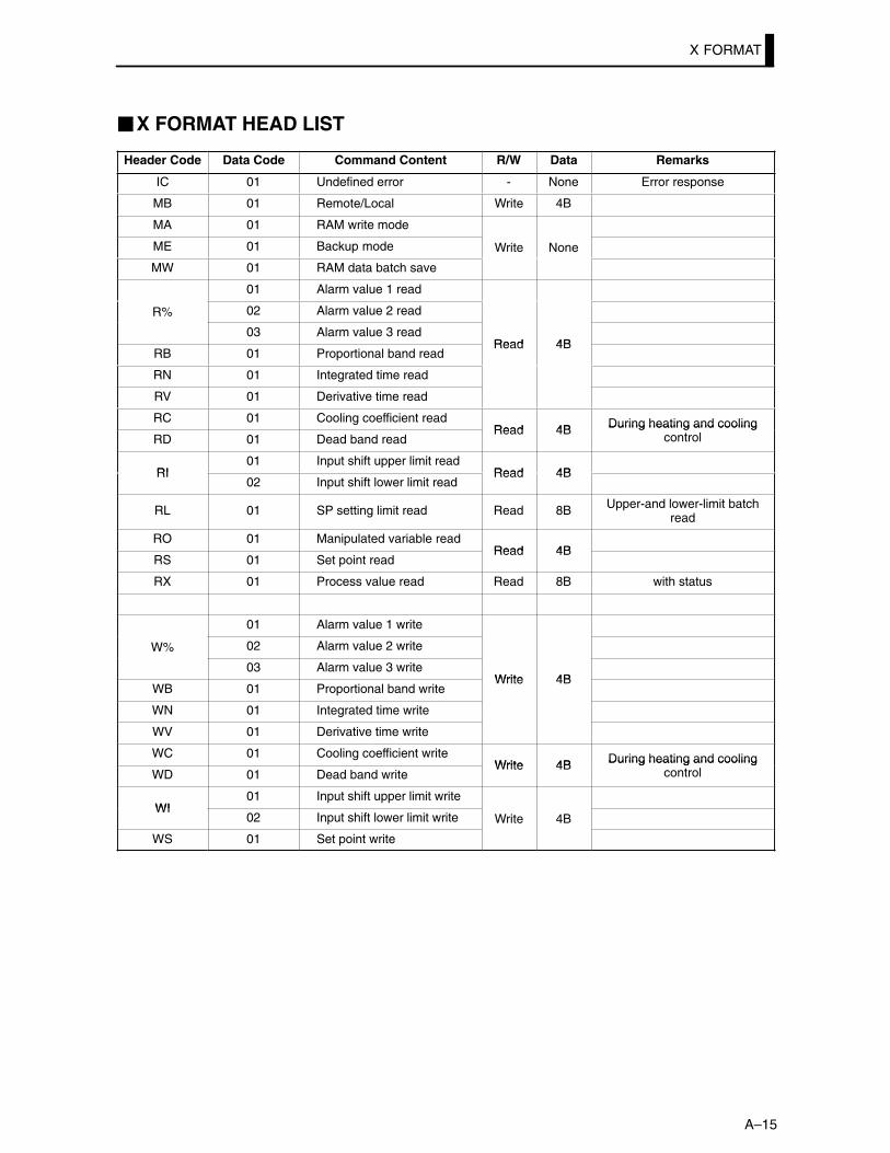
X FORMAT
A–15
�X FORMAT HEAD LIST
Header Code Data Code Command Content R/W Data Remarks
IC 01 Undefined error - None Error response
MB 01 Remote/Local Write 4B
MA 01 RAM write mode
ME 01 Backup mode Write None
MW 01 RAM data batch save
01 Alarm value 1 read
R% 02 Alarm value 2 read
03 Alarm value 3 readRead 4B
RB 01 Proportional band readRead 4B
RN 01 Integrated time read
RV 01 Derivative time read
RC 01 Cooling coefficient readRead 4B During heating and cooling
RD 01 Dead band readRead 4B During heating and cooling
control
RI01 Input shift upper limit read
Read 4BRI02 Input shift lower limit read
Read 4B
RL 01 SP setting limit read Read 8B Upper-and lower-limit batchread
RO 01 Manipulated variable readRead 4B
RS 01 Set point readRead 4B
RX 01 Process value read Read 8B with status
01 Alarm value 1 write
W% 02 Alarm value 2 write
03 Alarm value 3 writeWrite 4B
WB 01 Proportional band writeWrite 4B
WN 01 Integrated time write
WV 01 Derivative time write
WC 01 Cooling coefficient writeWrite 4B During heating and cooling
WD 01 Dead band writeWrite 4B During heating and cooling
control
WI01 Input shift upper limit write
WI02 Input shift lower limit write Write 4B
WS 01 Set point write
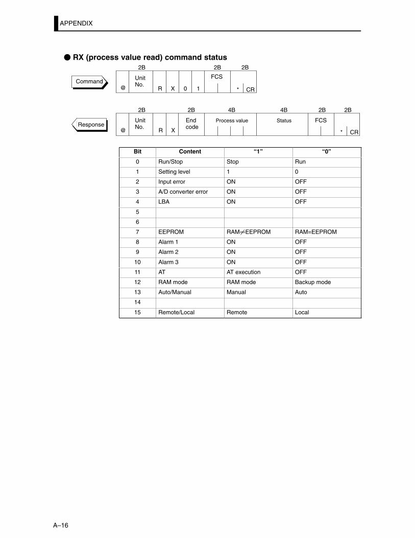
APPENDIX
A–16
� RX (process value read) command status
CommandUnitNo.
FCS
CR
UnitNo.
Process value FCS
CR
Endcode
@
@
*
*
2B 2B 2B
2B 4B 2B 2B2B
R X 0 1
RResponse
X
4B
Status
Bit Content “1” “0”
0 Run/Stop Stop Run
1 Setting level 1 0
2 Input error ON OFF
3 A/D converter error ON OFF
4 LBA ON OFF
5
6
7 EEPROM RAM�EEPROM RAM=EEPROM
8 Alarm 1 ON OFF
9 Alarm 2 ON OFF
10 Alarm 3 ON OFF
11 AT AT execution OFF
12 RAM mode RAM mode Backup mode
13 Auto/Manual Manual Auto
14
15 Remote/Local Remote Local
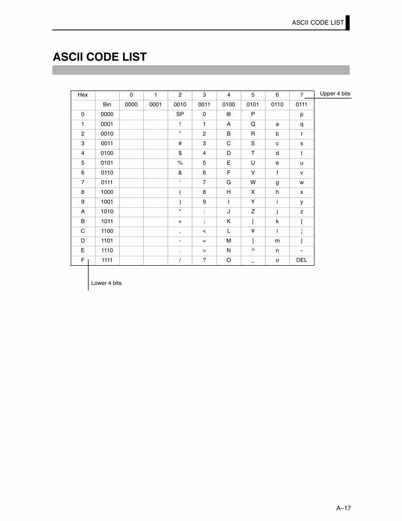
ASCII CODE LIST
A–17
ASCII CODE LIST
Hex 0 1 2 3 4 5 6 7
Bin 0000 0001 0010 0011 0100 0101 0110 0111
0 0000 SP 0 @ P p
1 0001 ! 1 A Q a q
2 0010 ” 2 B R b r
3 0011 # 3 C S c s
4 0100 $ 4 D T d t
5 0101 % 5 E U e u
6 0110 & 6 F V f v
7 0111 ’ 7 G W g w
8 1000 ( 8 H X h x
9 1001 ) 9 I Y i y
A 1010 * : J Z j z
B 1011 + ; K [ k {
C 1100 , < L ¥ l |
D 1101 - = M ] m }
E 1110 . > N ^ n ~
F 1111 / ? O _ o DEL
Upper 4 bits
Lower 4 bits
Revision History
)���������.���������� ��������������1����������������&���������������.���������������
�����+��B@>E#�:#@<�
3�.��������
��������������&����������������������������������������������������.������$������&����������� ��.���.������
Revision code Date Revised content
1 September 1995 Original production
2 April 1996 Page IV: Changed “100 to 240 VAC” to “AC100–240V or AC/DC24V”.
Page 1–3: Modified the spellings in Operation indicators.Page 1–7: Modified the diagram of mode.
Page 2–6: Modified the power specifications in “Terminalarrangement”.
Page 2–7: Modified the diagram in “Control output“.Page 3–2: Modified the diagram in “Setup”.Page 3–8: Added some texts to summary of alarm operations.Page 3–9: Changed “temperature” to “humidity”.
Added“upper and” to the text of step (4).Page 3–12: Changed “temperature” to“humidity” in “Setting example”
Changed“�C” to “%” in “Setting example”.Page 3–13: Moved a block(that was the 7th bullet) to the end of the
step (4) of “Setting example”on page 3–14.Page 4–5: Modified the diagram in “Set point limiter”.Page 4–7: Added some texts to “Input assignments”, “Run/Stop”
and “Auto/Manual”.Page 4–11: Changed a text in the diagram.Page 4–12: Added text to Preparations.Page 4–15: Modified the diagram in “Preparation”.Page 4–17: Modified the diagram in “Preparation”.
Changed “voltage” to “current” in step (9).Page 4–18: Modified the diagram in “Preparation”.Page 4–20: Modified the diagrams on this page.Page 5–2: Added some texts to the meanings of the model icons.Page 5–3: Added some texts to the comment descriptions.Page 5–5: Added some texts to Manual Mode.Page 5–6: Added some texts to Level 0 Mode.Page 5–7: Deleted “Related parameters”in “Set point during SP
ramp”.Page 5–17: Deleted some texts in “LBA detection time”.Page 5–18: Added a sentence to the Function descriptions.Page 5–27: Changed “SP setting” to “Set point”on the table.Page 5–30: Added some texts to Condition A:.Page 5–34: Changed the descriptions of “Related article”.Page 6–3: Changed the diagram of RS–232C.Page 6–7: Changed “–999.9” to “–199.9”in the parameters No.53
and 54.Page 6–9: Added a sentence to Run/Stop.Page 6–10: Added the“End code“.Page 6–13: Changed the program address No. “1110” to “1120”.Page 7–6: Changed “Not possible only with 40%AT” to “40%AT”on
the table.Page A–2: Changed the table of “Ratings”.Page A–3: Changed “0.1%FS” to “0.01%FS” in the description of
Hysteresis on table.Page A–5: Added some texts to the diagram.Page A–6,7:Modified the setting list table.Page A–10: Changed the descriptions of “ SRT Startup Conditions ”.Page A–13: Modified the list table of “Model list”.
2A July 1996 Page 6–9: Changed the table of “Instruction Code”.
2B September 1996 Page 1–7: Modified the diagram in “Selecting modes”.Page 5–33: Changed the Event Input Operation “ON:Run” to
“OFF:Run”.Page A–2: Added text to *1.Page A–8: Modified the diagram in “PARAMETER OPERATIONS
LIST”.Page A–10: Changed the letter “k” to “K”.
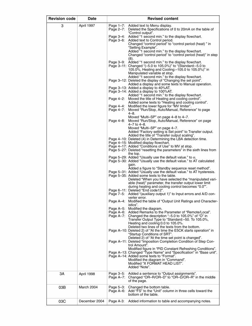
Revision code Revised contentDate
3 April 1997 Page 1–7: Added text to Menu display.Page 2–7: Deleted the Specifications of 0 to 20mA on the table of
“Control output”.Page 3–4: Added “1 second min.” to the display flowchart.Page 3–6: Added text to Control period.
Changed “control period” to “control period (heat) ” in“Setting Example”.Added “1 second min.” to the display flowchart.Changed “control period” to “control period (heat)” in step(8).
Page 3–9: Added “1 second min.” to the display flowchart.Page 3–11: Changed “(–5.0 to 105.0%)” to “(Standard:–5.0 to
105.0%, Heating and Cooling:–105.0 to 105.0%)” inManipulated variable at stop.Added “1 second min.” to the display flowchart.
Page 3–12: Deleted the display of “Changing the set point”.Added a display and some texts to Manual operation.
Page 3–13: Added a display to 40%AT.Page 3–14: Added a display to 100%AT.
Added “1 second min.” to the display flowchart.Page 4–2: Moved the title of Heating and cooling control”.
Added some texts to “Heating and cooling control”.Page 4–4: Modified the lower figure for “MV limiter”.Page 4–7: Moved “Run/Stop, Auto/Manual, Reference” to page
4–8.Moved “Multi–SP” on page 4–8 to 4–7.
Page 4–8: Moved “Run/Stop, Auto/Manual, Reference” on page4–7 to 4–8.Moved “Multi–SP” on page 4–7.Added “Factory setting is Set point” to Transfer output.Added the title of “Transfer output scaling”.
Page 4–10: Deleted (4) in Determining the LBA detection time.Page 4–15: Modified display flowchart.Page 4–17: Added “Conditions of Use” to MV at stop.Page 5–27: Deleted “resetting the parameters” in the sixth lines from
the top.Page 5–29: Added “Usually use the default value.” to α.Page 5–30: Added “Usually use the default value.” to AT calculated
gain.Added a figure to “Standby sequence reset method”.
Page 5–31: Added “Usually use the default value.” to AT hysteresis.Page 5–35: Added some texts to the table.
Deleted “When you have selected the “manipulated vari-able (heat)” parameter, the transfer output lower limitduring heating and cooling control becomes “0.0””.
Page 6–11: Deleted “End code12”.Page 7–5: Added “(auxiliary output 1)” to Input errors and A/D con-
verter error.Page A–4: Modified the table of “Output Unit Ratings and Character-
istics”.Page A–5: Modified the diagram.Page A–6: Added Remarks to the Parameter of “Remote/Local”.Page A–7: Changed the description “–5.0 to 105.0%” of “O” in
Transfer Output Type to “Standard:–50. To 105.0%,Heating and cooling:0.0 to 105.0%.Deleted two lines of the texts from the bottom.
Page A–10: Deleted 2) of “At the time the E5CK starts operation” in“Startup Conditions of SRT”.Deleted 2) of “At the time set point is changed”.
Page A–11: Deleted “Imposition Completion Condition of Step Con-trol Amount”.Modified figure in “PID Constant Refreshing Conditions”.
Page A–13: Changed “Type Name” and “Specification” in “Base unit”.Page A–14: Added some texts to “Format”.
Modified the diagram in “Command”.Modified “X FORMAT HEAD LIST”.Added “Note”.
3A April 1998 Page 3–5: Added a sentence to “Output assignments”.Page A–7: Changed “OR–R/OR–D” to “OR–D/OR–R” in the middle
of the page.
03B March 2004 Page 5–3: Changed the bottom table.Page A–6: Add “FS” to the “Unit” column in three cells toward the
bottom of the table.
03C December 2004 Page A-3: Added information to table and accompanying notes.
INDEX
A)=?���.���������� <F��>F���������������������������
)=%���� :F<����������������������������������������������������������
)=%����� ����� <F:@������������������������������������������
J)=%K����� ����� �F,����������������������������������������
)��**��2?��'*�� )F:>����������������������������������
)���1����=������ �F:@������������������������������������
)���������������� �F<@������������������������������������
)������������ �F<:����������������������������������������������
)&������&����� :F:@��������������������������������������
)&����.����� ��������� /F>��������������������������
)&��$*?�$��������� <F:,����������������������������
)&������?�������$����������)�����A��� <FG��������������������������������������
)&������ ����&���� ;F/������������������������������
)&�������.������ ��������� ������J�.���� �� �K ,F>��������������������������
)�5������������2 ������ <F:;������������������
)�����:����������� �F:G������������������������������������
)�����:� ����������� �F;/������������������������������
)�����:��� � �F;�����������������������������������������������
)�����;����������� �F:G������������������������������������
)�����;� ����������� �F;/������������������������������
)�����;��� � �F;�����������������������������������������������
)�����<����������� �F:G������������������������������������
)�����<� ����������� �F;/������������������������������
)�����<��� � �F;�����������������������������������������������
)��������������� <FE������������������������������������������
)������� � <F>����������������������������������������������������
)�����.��� <F>��������������������������������������������������
)�����.����: <F>��F::����������������������������������
)�����.����; <F>��F::����������������������������������
)�����.����< <F>��F::����������������������������������
)�#����� )���! :F<�<F:<����������������������������
)�=%���� <F:;�,F>������������������������������������
)������������������ ������� �F<:����������
)1�������� ��:����������� �F;�����������������
)1�������� ��:J���������+��K ;FE����������
B(������#������(� #�����2 ������ <F:;��������
C�2+�32'�('2���?*)Q3)% )F���������������
��&��C���������J�����������K /F<������
����&���������������� � ,F:>������������������������
����&������C�� �� :F:@������������������������������������
����&������� ���������������������������� ,F:�����������������������������������������������
����&������C������ �� ,F:;������������������������
����&������C���������� � :F:@��������������������
����&�������.�������� � ,F:E������������������������
����&����� ,F::��������������������������������������������������
����&�������������� ,F:;����������������������������
����&��������� :F>��F</����������������������������
����&��������.������ ,F:;������������������������������
����������������� ��� <F:;������������������������������
�������������������������� ,F;@������������������
�������������= ����������� <FE��������������������
�����������������J�����������K /F�����������������������������������
������������3�� ����J�����������K /F/����������������������������������
�����������&������� �F<,����������������������
���������������������� �F<,��������������������
����������� ����� �F<,������������������������������
������������� �&�� �F<,��������������������������
���������������+� �F<,��������������������������
������������ ��������� /F,��������������������
������������������H����������� ,F:;����������������������������������������������
������� ��:����������� �F;,������������������
������� ��;����������� �F;,������������������
������� �J���������+��K ;F>����������������
������ ���� <F/����������������������������������������������
������ ���� ��! �F:,����������������������������������
������ ���� ����! �F:,����������������������������������
���������������� ,F;��F:;��������������������������
��������� � :F,����������������������������������������������
D?����&��� ,F;��F:;������������������������������������������
?������� ��� �F;<��������������������������������������������
?���.���.������ �F::������������������������������������������
?�������� ;F,��������������������������������������������������
?�����=��.����� ������ <F���F;/����������������
?������� :F<������������������������������������������������������
?���#� ;F;��������������������������������������������������������
E�����?�� ��� >F<������������������������������������������������
������ � >F�������������������������������������������������
�.������ � :F,�,F>����������������������������������������
�.������ �������������: �F<<������������������������
�1 ��������� :F/��F;>������������������������������
F4�1������������ :FE����������������������������������������������
4���� ���� :F;��������������������������������������������������
HB���������������������� ,F;����������������������
B����3�������������������� *�������� /F:@��������������������������������
INDEX
B����"���2 ����4������ ,F>������������������
B����������� :F<��������������������������������������������
B��������� ,F<������������������������������������������������������
B��������� ��! �F:<������������������������������������������
B��������� ����! �F:<����������������������������������������
I*� ������2� � :F,����������������������������������������
*� ������������� ,F>��������������������������������������
*� ���������������� �F:G��������������������������������������
*� ������� >F���������������������������������������������������
*� ������� <F<����������������������������������������������������
*� ������������������ <F<��F;@��������������������
*� �������� �������� <F<��F;@��������������������
*� ���� � <F<��F;;������������������������������������������
*� ��J���������+��K ;F/��������������������������������
*���������� ;F,����������������������������������������������������
*������������ �F::����������������������������������������������
*�������� /F;��������������������������������������������������������
*������� ������������� /FG��������������������������
L'() ,FG�>F�������������������������������������������������������
'()�����������1�� �� ,FG������������������������������
'()�������������� ,FG��F:>��������������������������
'()��������������� ,FG��F<:����������������������
'�.���@���� :F/��F/��������������������������������������
'�.���:���� :F/��FG��������������������������������������
'�.���;���� :F/��F:�������������������������������������
'������� ��������������� ,F���������������������
M%)+" :F<������������������������������������������������������������
%A����$A����� �F:>������������������������������������������
%A������������������ �F:E��������������������������������
%A�������������������� ,F,������������������������������
%A�������� ,F,����������������������������������������������������
%A����������� �F:E������������������������������������������
%A������ ��! �F>����������������������������������������
%A������ ����! �F>����������������������������������������
%A� �������� �F:E������������������������������������������
%���� ���� :F;����������������������������������������������������
%��� ������.����&�������� <F::�,F;��������
%��� ������.����&�������������� ,F,������������
%�����%A �F���������������������������������������������������
%�������� :F/��F���������������������������������������
%����� ������ <F:;��������������������������������������
%�����������.��� �F:<������������������������������������
%������ ��� :F>������������������������������������������������
%������ :F<��������������������������������������������������������
%����'��� )F:<��������������������������������������������������
%����� ;F�������������������������������������������������������
%���#�$ ,FE��������������������������������������������������������
%���#�$������� �F<<��������������������������������������
N+������� ���� :F;��������������������������������������������
+��:���� ��� :F<������������������������������������������������
+��;���� ��� :F<������������������������������������������������
O2+=244������ ,F<������������������������������������������
2"�: :F<������������������������������������������������������������
2"�; :F<������������������������������������������������������������
2 ����������������3���������� ,F,������������
2 ����������������J�$���� K ,F/��������������������
2 ������� ��������� :F<����������������������������������
2 ������� :F>��F<;������������������������������������
2 ����J���������+��K ;FE������������������������������
2� ������������� :F��<F���������������������������
P$)3)%���3�2$�3)�*2+��'*�� )FE������
$)3)%���3� �F:��������������������������������������������
$*?=2+=244 �F;E����������������������������������������������
$A=�$ �F/������������������������������������������������������������
$�������� ;F,��������������������������������������������������
$�����������������6� �F;<����������������������������������
$����������� �� :F/������������������������������������������
$��������������%��� :F/������������������������������
$���������������������������� ,F;@��������
$�������������������� ;F/��������������������������
$� ������� &��� �F::������������������������������������
$��������� :F/�<F:@��F<����������������������������
R3%� :F<��������������������������������������������������������������
3�F;<;� :FG�/F<��������������������������������������������
3�F,E� :FG�/F<������������������������������������������������
3�����������������J�����������K /FE����
3������=�������� ��������� /F/����������������������
3���������������&���������� :F:@��������������������
3����='��� �F:/����������������������������������������������
3������������������$���� ,F/��������������������
3�=�� ,F>��FE����������������������������������������������
S����*+Q�'*�� )F/����������������������������������������
�$���� ,F���������������������������������������������������������
�$���� �����.��� �F:/��������������������������������������
�$���� ��������� �F:/������������������������������������
�$������������������� �F;E������������������������������
�$��������� �������� �F;E������������������������������
INDEX
�$��*4*�)�*2+� )F;������������������������������������
�� �F;G������������������������������������������������������������������
������&�������� �F;G������������������������������������������
��2$ :F<��������������������������������������������������������������
�"(: :F<��������������������������������������������������������������
������� <F<������������������������������������������������������������
������������������ �F;<������������������������������������
�������� �������� �F;<������������������������������������
������� <F:@��F<����������������������������������������������
�������������� :F>��������������������������������������������
���������� ��������� :FE����������������������������������
��������������������%���� ,F;��������������������
���� ����@ �F:@��������������������������������������������������
���� ����: �F:@��������������������������������������������������
���� �����������$���� �F>��������������������������
���� ����������� ,F�������������������������������������������
��������)������� � <F>������������������������������������
��������*� ��� ����������� <F<����������������������
��������2� ��� ����������� <F�������������������
������������������������ ����������� /F,������������������������������������������
�������������� ���� � ;F;��������������������������������
�������� ;F;������������������������������������������������������
��� ���� :F/��F;:����������������������������������������
�����&����-���� <FE����������������������������������������
�����&����-���������������� �F<@��������������
��������������� ����2 ������ <F::����������
��������������� ������� <FE������������������
T�32"('��B22�*+Q >F:������������������������������
��� ��������� � :F,��������������������������������������
�������������������� ;F/������������������������������
������ �� ,F;@��������������������������������������������
���������� � :F��,FE����������������������������������
���������� ������������ �F<���������������������
���������� ���� � �F<���������������������������������
���������� �� �������� �F<���������������������
��������� �������J�����������K /F;����
U" ����� :F<����������������������������������������������������������
VA�������� � :F,������������������������������������������������
W9��������������� ;F/����������������������������������������
9���������������A��� /F/����������������������������������
XO�423%)� )F:,����������������������������������������������
°�=°4��������� �F;,��������������������������������������������
α �F;G��������������������������������������������������������������������
H078-E1-03C


![FIGURE 8.1 Process and controller. Curtis Johnson Process Control Instrumentation Technology, 8e] Copyright ©2006 by Pearson Education, Inc. Upper Saddle](https://img.pdfslide.us/doc/110x75/5515178e550346a80c8b5e70/figure-81-process-and-controller-curtis-johnson-process-control-instrumentation-technology-8e-copyright-2006-by-pearson-education-inc-upper-saddle.jpg)


![FIGURE 10.1 Typical physical appearance of a controller. Curtis Johnson Process Control Instrumentation Technology, 8e] Copyright ©2006 by Pearson Education,](https://img.pdfslide.us/doc/110x75/551517825503465e608b4f51/figure-101-typical-physical-appearance-of-a-controller-curtis-johnson-process-control-instrumentation-technology-8e-copyright-2006-by-pearson-education.jpg)