Embed Size (px)
Citation preview
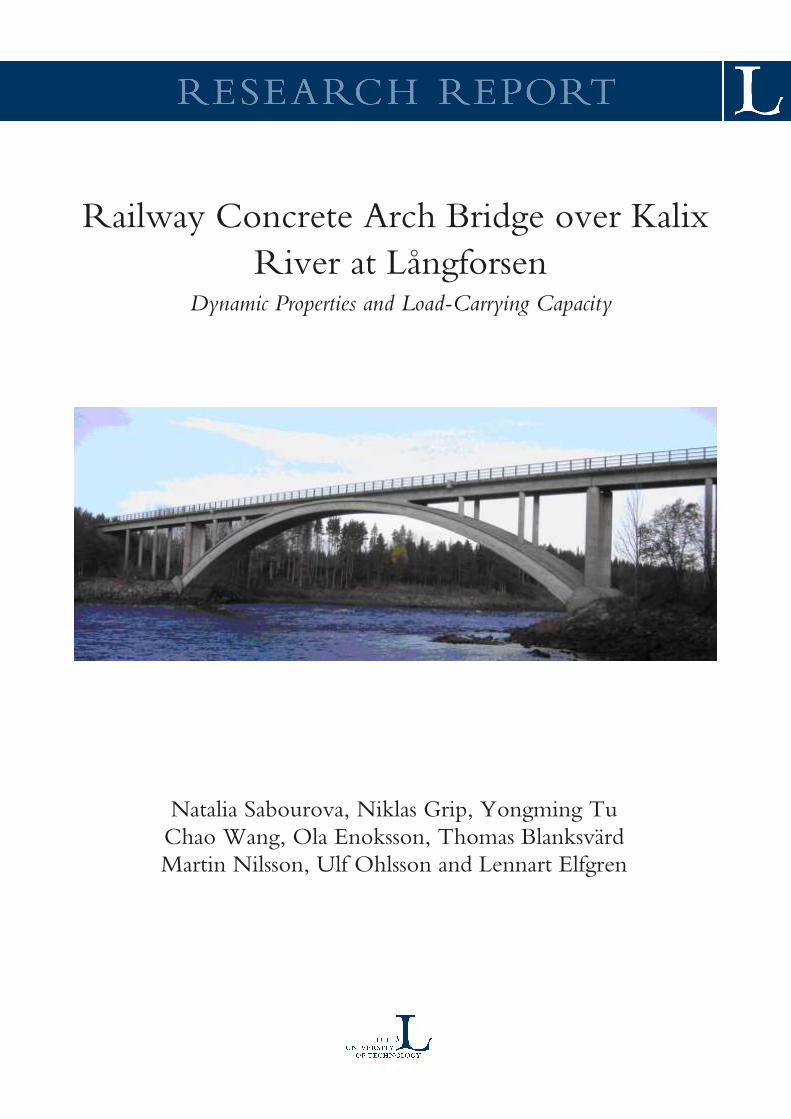
Railway Concrete Arch Bridge over Kalix
River at LångforsenDynamic Properties and Load-Carrying Capacity
Natalia Sabourova, Niklas Grip, Yongming TuChao Wang, Ola Enoksson, Thomas BlanksvärdMartin Nilsson, Ulf Ohlsson and Lennart Elfgren

Railway Concrete Arch Bridge over
Kalix River at Långforsen
Dynamic Properties and Load-Carrying Capacity
Natalia Sabourova, Niklas Grip, Yongming TuChao Wang, Ola Enoksson, Thomas BlanksvärdMartin Nilsson, Ulf Ohlsson, and Lennart Elfgren
Luleå University of TechnologyDepartment of Civil, Environmental and Natural Resources
Division of Structural Engineering

Luleå University of Technology
ISSN 1402-1528 ISBN 978-91-7790-473-1 (pdf)
Luleå 2019
www.ltu.se
4
Abstract
The concrete arch bridge over Kalix River at Långforsen was built in 1960 and has a mid-span
of 89,5 m and a height of 13,7 m. The bridge owner, Trafikverket wanted to increase its
allowable axle load from 225 to 300 kN. Field tests were carried out under service condition
and with ambient vibrations. The test results were used to update and validate Finite Element
Models. At last, the refined models were used to check the possibility to increase the axle load.
According to earlier assessments, most parts of the bridge is capable of carrying an axle load
of 330 kN. The only critical sections are located in the beams carrying the rail on top of the
arch in the section where the beams are united with the arch. Here the stresses in the longitudinal
bottom reinforcement are slightly too high.
These sections have been studied in a FEM model for different loads and results show
maximum strains of about 50·10-6 corresponding to stresses of only about 10 MPa in the
reinforcement in the critical sections. Live load vertical deflections of the crown of the arch is
of the order of only ± 6 mm. Dynamic studies have also been made showing that fatigue is no
issue. Altogether the studies show that the bridge is able to carry an increased axle load of 300
kN without problems.
Photo on cover (2009-10-05): The bridge over Kalix River at Långforsen was built in 1960
and has a total length of 176,5 m and a mid-span length of 89,5 m. It is situated in the north
of Sweden some 10 km NW of Kalix and some 60 km W of the border to Finland.
5
Preface
The work presented in this report was initiated by Banverket (now Trafikverket) in order to
assess the possibility to increase the allowable loads on the railway concrete arch bridge over
Kalix River at Långforsen.
Measurements on the bridge were performed in 2009 and 2011 by Complab at Luleå
University of Technology. The measurements during 2009 were planned by Mr. Ola
Enoksson, Tekn. Lic., and analyzed by Associate Professors Martin Nilsson, Tekn. Dr., and
Thomas Blanksvärd, Tekn. Dr. The measurements during 2011 were planned and analyzed by
Ms. Natalia Sabourova, Fil. Lic., Associate Professor Niklas Grip, Fil. Dr., and Guest
Professor Yongming Tu, Ph. D. From Complab, Messrs. Georg Danielson, Håkan Johansson,
Mats Petersson and Lars Åström have taken part. Assistant Professor Ulf Ohlsson, Tekn. Dr.
and Senior Professor Lennart Elfgren, Tekn. Dr., have guided the work.
Different finite element models have been constructed during 2009-2012. Preliminary
models were constructed by guest student Huang Wei from Central South University of
Forestry and Technology in Changsha, China, and by Ph. D. student Arto Puurula, Tekn. Lic.,
from Savonia University of Applied Sciences, Kuopio, Finland. The final model has been
constructed by Guest Professor Yongming Tu from Southeast University in Nanjing, China.
During 2016-18 the model has been improved by Mr. Chao Wang, guest Ph D student at
LTU, also from Southeast University in Nanjing, China.
In this report Ola Enoksson and Lennart Elfgren have compiled most of chapters 1-3 and
Appendices A-D, Natalia Sabourova and Niklas Grip most of chapter 4 and Appendix E,
Yongming Tu most of chapter 5 and Appendix F, while all the authors have contributed to
chapter 7. Draft versions were prepared in 2012 and 2016. The final editing in 2019 has been
done by Lennart Elfgren
The work has in different phases been supported by Banverket (now Trafikverket), the
Swedish Research Council for Environment, Agricultural Sciences and Spatial Planning
(Formas, dnr 2012–1037), the Development Fund of the Swedish Construction Industry
(SBUF, id 12513, 13010), Luleå Centre for Risk Analysis and Risk Management (CRR),
Luleå Railway Research Centre (JVTC), the European Regional Funds and Luleå University
of Technology.
Luleå in September 2019
Natalia Sabourova, Niklas Grip, Yongming Tu, Chao Wang, Ola Enoksson
Thomas Blanksvärd, Martin Nilsson, Ulf Ohlsson and Lennart Elfgren
6
Table of Contents
Abstract ...................................................................................................................................... 4
Preface ........................................................................................................................................ 5
Table of Contents ....................................................................................................................... 6
1. Introduction ............................................................................................................................ 8
1.1 Background ....................................................................................................................... 8
1.2 Historical note on arch bridges ......................................................................................... 9
1.3 The arch line ................................................................................................................... 10
1.4 Management and assessment of bridges ......................................................................... 12
2. Design and construction ....................................................................................................... 13
2.1 General ............................................................................................................................ 13
2.2 Concrete arch .................................................................................................................. 13
2.3 Top beams, columns and abutments ............................................................................... 19
2.4 Construction .................................................................................................................... 19
3. Geometry and material properties ........................................................................................ 21
3.1 Geometry ........................................................................................................................ 21
3.2 Material parameters ........................................................................................................ 21
4. Assessments 2002 -2004 ...................................................................................................... 23
4.1 General ............................................................................................................................ 23
4.2 Results ............................................................................................................................ 23
5. Measurements ....................................................................................................................... 26
5.1 Measurements during 2009 ............................................................................................ 26
5.2 Measurements during 2011 ............................................................................................ 26
6. Finite element models (FEM) .............................................................................................. 29
6.1 General ............................................................................................................................ 29
6.2 Design of Models ............................................................................................................ 30
6.3 Calibration and updating of models 2009-2012 ............................................................. 32
6.3 Calibration and updating of models 2016-2018 ............................................................. 33
7. Conclusions .......................................................................................................................... 35
References ................................................................................................................................ 36
7
Appendix A. Drawings from 1958 -1960
Appendix B. Design calculations from 1958
Appendix C. Photos from construction 1959
Appendix D. Assessment 2002-2004
Appendix E. Measurements 2010- 2012
Appendix F Finite Element Models
Notation
The symbols are explained where they are introduced.
A decimal comma (,) is used to separate integers from fractional parts of a number as
customary in Sweden but contrary to the English use of a decimal point (.)
8
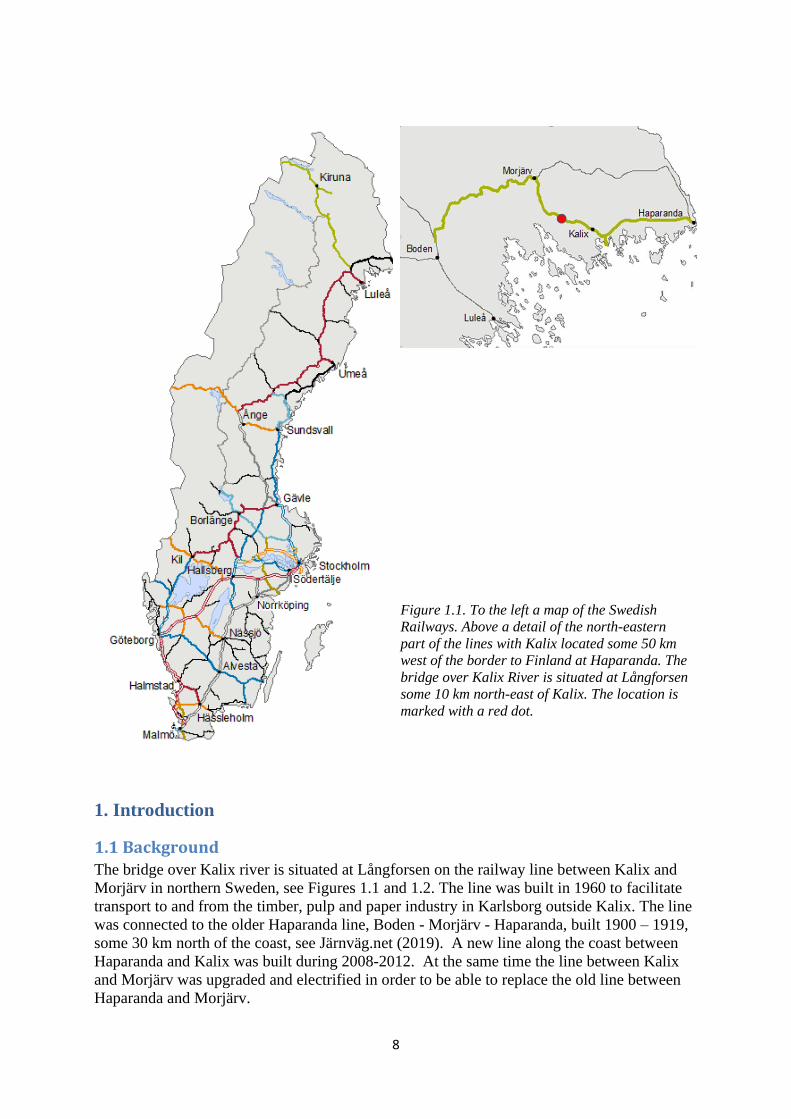
Figure 1.1. To the left a map of the Swedish
Railways. Above a detail of the north-eastern
part of the lines with Kalix located some 50 km
west of the border to Finland at Haparanda. The
bridge over Kalix River is situated at Långforsen
some 10 km north-east of Kalix. The location is
marked with a red dot.
1. Introduction
1.1 Background
The bridge over Kalix river is situated at Långforsen on the railway line between Kalix and
Morjärv in northern Sweden, see Figures 1.1 and 1.2. The line was built in 1960 to facilitate
transport to and from the timber, pulp and paper industry in Karlsborg outside Kalix. The line
was connected to the older Haparanda line, Boden - Morjärv - Haparanda, built 1900 – 1919,
some 30 km north of the coast, see Järnväg.net (2019). A new line along the coast between
Haparanda and Kalix was built during 2008-2012. At the same time the line between Kalix
and Morjärv was upgraded and electrified in order to be able to replace the old line between
Haparanda and Morjärv.
9
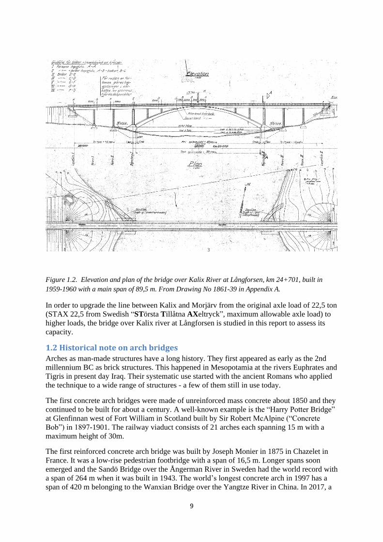
Figure 1.2. Elevation and plan of the bridge over Kalix River at Långforsen, km 24+701, built in
1959-1960 with a main span of 89,5 m. From Drawing No 1861-39 in Appendix A.
In order to upgrade the line between Kalix and Morjärv from the original axle load of 22,5 ton
(STAX 22,5 from Swedish “STörsta Tillåtna AXeltryck”, maximum allowable axle load) to
higher loads, the bridge over Kalix river at Långforsen is studied in this report to assess its
capacity.
1.2 Historical note on arch bridges
Arches as man-made structures have a long history. They first appeared as early as the 2nd
millennium BC as brick structures. This happened in Mesopotamia at the rivers Euphrates and
Tigris in present day Iraq. Their systematic use started with the ancient Romans who applied
the technique to a wide range of structures - a few of them still in use today.
The first concrete arch bridges were made of unreinforced mass concrete about 1850 and they
continued to be built for about a century. A well-known example is the “Harry Potter Bridge”
at Glenfinnan west of Fort William in Scotland built by Sir Robert McAlpine (“Concrete
Bob”) in 1897-1901. The railway viaduct consists of 21 arches each spanning 15 m with a
maximum height of 30m.
The first reinforced concrete arch bridge was built by Joseph Monier in 1875 in Chazelet in
France. It was a low-rise pedestrian footbridge with a span of 16,5 m. Longer spans soon
emerged and the Sandö Bridge over the Ångerman River in Sweden had the world record with
a span of 264 m when it was built in 1943. The world’s longest concrete arch in 1997 has a
span of 420 m belonging to the Wanxian Bridge over the Yangtze River in China. In 2017, a
10
span length of 445 m was reached at the Beipan River Bridge on the Shanghai-Kunming high
speed railway. The history of arch bridges is treated in many beautifully illustrated books as
e.g. Brown (1998), Graf (2002) and Fernández Troyano (2003). The theoretical development
is presented by e.g. Timoshenko (1953) and Kurrer (2008).
In Sweden reinforced concrete arch bridges started to be built around 1910, see Ahlberg-
Spade (2001). Early examples are the 50 m arch at Motala ström built in 1911 and the 90 m
arch built at Tällberg over Öre älv for the railway line to northern Sweden. The building of
this and other bridges is described in a Ph.D. thesis by Larsson (1997) about the bridge
builder Otto Linton.
Other railway arch bridges in northern Sweden are the 39,2 m bridge at Myrheden over Byske
älv from 1941 and the two 112,1 m arch bridges at Vindeln over the Vindel River from 1952
and at Ragunda over the Indal River from 1955. The bridge treated in this report, the 89,5 m
arch at Långforsen over the Kalix River was built in 1960. Assessments of the Byske bridge is
presented in Enochsson et al (2011) and of the Vindel Bridge in Enochsson et al (2005),
Bennitz (2006), He et al (2006, 2008) and Häggström and Martinsson (2009).
Other notable early Swedish road concrete arch bridges are the 181m span of the bridge at
Traneberg in Stockholm from 1934 and the earlier mentioned Sandö bridge from 1943 with
the world record span of 264 m
1.3 The arch line
Design of concrete arch bridges is treated by e.g. Strassner (1936), Gustafsson and
Müllersdorf (1961), Asplund (1966) and Lorentsen (1966).
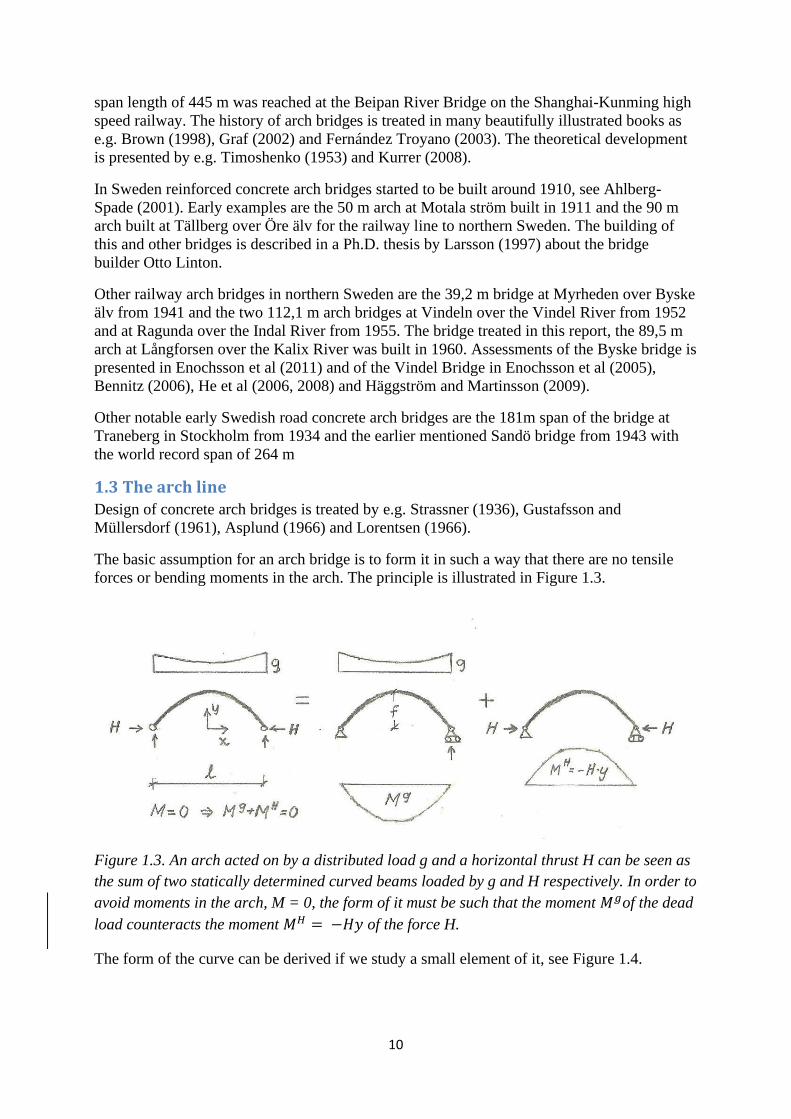
The basic assumption for an arch bridge is to form it in such a way that there are no tensile
forces or bending moments in the arch. The principle is illustrated in Figure 1.3.
Figure 1.3. An arch acted on by a distributed load g and a horizontal thrust H can be seen as
the sum of two statically determined curved beams loaded by g and H respectively. In order to
avoid moments in the arch, M = 0, the form of it must be such that the moment 𝑀𝑔of the dead
load counteracts the moment 𝑀𝐻 = −𝐻𝑦 of the force H.
The form of the curve can be derived if we study a small element of it, see Figure 1.4.
11
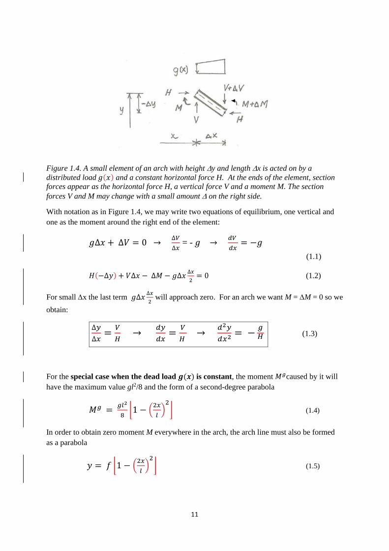
Figure 1.4. A small element of an arch with height y and length x is acted on by a
distributed load 𝑔(𝑥) and a constant horizontal force H. At the ends of the element, section
forces appear as the horizontal force H, a vertical force V and a moment M. The section
forces V and M may change with a small amount on the right side.
With notation as in Figure 1.4, we may write two equations of equilibrium, one vertical and
one as the moment around the right end of the element:
𝑔∆𝑥 + ∆𝑉 = 0 → ∆𝑉
∆𝑥 = - 𝑔 →
𝑑𝑉
𝑑𝑥= −𝑔
(1.1)
𝐻(−∆𝑦) + 𝑉∆𝑥 − ∆𝑀 − 𝑔∆𝑥∆𝑥
2= 0 (1.2)
For small x the last term 𝑔∆𝑥∆𝑥
2 will approach zero. For an arch we want M = M = 0 so we
obtain:
∆𝑦
∆𝑥=
𝑉
𝐻 →
𝑑𝑦
𝑑𝑥=
𝑉
𝐻 →
𝑑2𝑦
𝑑𝑥2 = −𝑔𝐻 (1.3)
For the special case when the dead load 𝒈(𝒙) is constant, the moment 𝑀𝑔caused by it will
have the maximum value gl2/8 and the form of a second-degree parabola
𝑀𝑔 = 𝑔𝑙2
8⌊1 − (
2𝑥
𝑙)
2
⌋ (1.4)
In order to obtain zero moment M everywhere in the arch, the arch line must also be formed
as a parabola
𝑦 = 𝑓 ⌊1 − (2𝑥
𝑙)
2
⌋ (1.5)
12
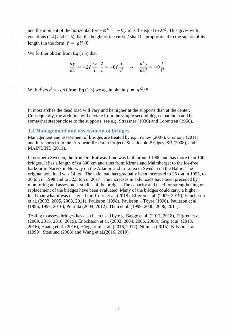
and the moment of the horizontal force 𝑀𝐻 = −𝐻𝑦 must be equal to 𝑀𝑔. This gives with
equations (1.4) and (1.5) that the height of the curve f shall be proportional to the square of its
length l in the form 𝑓 = 𝑔𝑙2 8⁄
We further obtain from Eq (1.5) that
𝑑𝑦
𝑑𝑥 = −2𝑓
2𝑥
𝑙∙
2
𝑙= −8𝑓
𝑥
𝑙2 →
𝑑2𝑦
𝑑𝑥2= −8
𝑓
𝑙2
With d2y/dx2 = - g/H from Eq.(1.3) we again obtain 𝑓 = 𝑔𝑙2 8.⁄
In most arches the dead load will vary and be higher at the supports than at the center.
Consequently, the arch line will deviate from the simple second-degree parabola and be
somewhat steeper close to the supports, see e.g. Strassner (1936) and Lorentsen (1966).
1.4 Management and assessment of bridges
Management and assessment of bridges are treated by e.g. Yanev (2007), Cremona (2011)
and in reports from the European Research Projects Sustainable Bridges, SB (2008), and
MAINLINE (2011).
In northern Sweden, the Iron Ore Railway Line was built around 1900 and has more than 100
bridges. It has a length of ca 500 km and runs from Kiruna and Malmberget to the ice-free
harbour in Narvik in Norway on the Atlantic and to Luleå in Sweden on the Baltic. The
original axle load was 14 ton. The axle load has gradually been increased to 25 ton in 1955, to
30 ton in 1998 and to 32,5 ton in 2017. The increases in axle loads have been preceded by
monitoring and assessment studies of the bridges. The capacity and need for strengthening or
replacement of the bridges have been evaluated. Many of the bridges could carry a higher
load than what it was designed for, Coric et al. (2018), Elfgren et al. (2009, 2019), Enochsson
et al. (2002, 2005, 2008, 2011), Paulsson (1998), Paulsson – Töyrä (1996), Paulsson et al.
(1996, 1997, 2016), Puurula (2004, 2012), Thun et al. (1999, 2000, 2006, 2011).
Testing to assess bridges has also been used by e.g. Bagge et al. (2017, 2018), Elfgren et al.
(2009, 2015, 2018, 2019), Enochsson et al. (2002, 2004, 2005, 2008), Grip et al. (2013,
2016), Huang et al. (2016), Häggström et al. (2016, 2017), Nilimaa (2015), Nilsson et al.
(1999), Stenlund (2008) and Wang et al.(2016, 2019).
13
2. Design and construction
2.1 General
The railway bridge over Kalix River at Långforsen, km 24+701, has a total length of 177.3 m
with a central arch of 89,5 m and two side spans of 42 m, see Figures 1.2 and 2.1. The free
spans have lengths of 13,0 + 12,8 +12,6 + 87,92 +12,6 + 12,8 + 13,0 m = 164,7 m.
The bridge was designed by Uno Nordstrand at Kungliga Järnvägsstyrelsen during 1956-58
and built in 1960 by Nya Asfalt AB. The bridge consists of an arch which carries a reinforced
concrete slab via underlying longitudinal and transversal concrete beams, connected through
fixed columns. The arch consists of a reinforced concrete hollow box girder with two hollow
spaces. The cross section is lowest at the crown of the arc and highest at the connection to the
arch abutment. The original drawings of the bridge are given in Appendix A and the original
design calculations in Appendix B.
The design train load corresponds to an axle load of 250 kN for the locomotive and a
distributed load of 85 kN/m for the wagons.
The design was based on Strassner (1936) and Uno Nordstrand made the following
assumptions (see page B6, i.e. page 6 in Appendix B):
Length of the span l = 89,5 m
Height of arch f = 13,45 m which gives f/l = 0,15
The arch is formed after the compression line for the dead load. The moment of inertia is
varied according to Strassner:
𝐼𝑠
𝐼𝑧 ∙ cos 𝜑 = 1 − (1 − 𝜂)𝜉 or 𝐼𝑧 =
𝐼𝑠
[1(1−𝜂)𝜉]𝑐𝑜𝑠𝜑 with
Iz = the moment of inertia at the horizontal coordinate z measured from the center of the arch
Is = the moment of inertia at the center of the arch (index s possibly from superior)
Ik = the moment of inertia at the support (index k possibly from German kant = end)
φ = is the angle of the arch in relation to the horizontal axis
𝜉 = 2s/s0 is the relative distance along the arch from the center. The total arch length is s0
𝜂 = 𝐼𝑠
𝐼𝑘 ∙ cos 𝜑𝑘
2.2 Concrete arch
Nordstrand (1958) assumes that the ratio m of the dead loads at the end and the center of the
arch is m = gk/gs = 2 which according to Strassner gives him cos φk = 0,8254 and φk = 34,4 o.
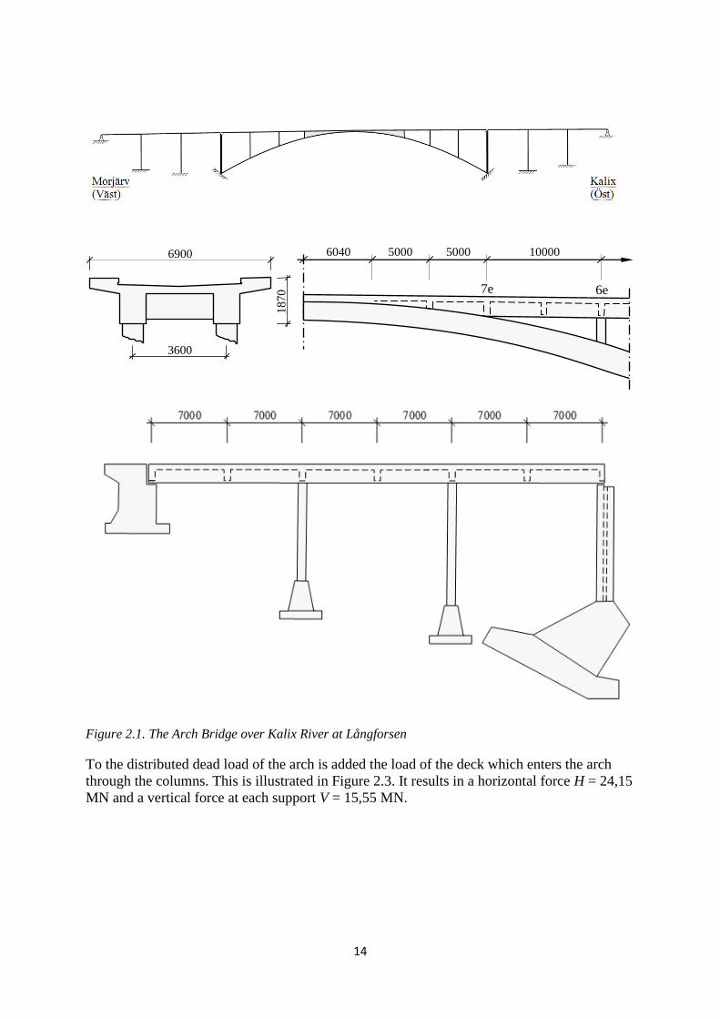
He then assumes a geometry of the arch section, see Figure 2.2, and starts at the end with a
height of Hk = 2,8 m, a width Bk = 6,3 m, an area Ak = 8,193 m2 and a moment of inertia Ik
= 8,896 m4 and obtains at the centre (head) of the arch that Hs = 1,8 m, Bs = 5,4 m, As =
4,830 m2 and Is = 2,169 m4 = 0,24 Ik. For the deck he assumes an area Af = 5,474 m2 and a
moment of inertia If = 1,606 m4. These values are later refined,
14
10000 5000 5000 6040
6e 7e
6900
3600
18
70
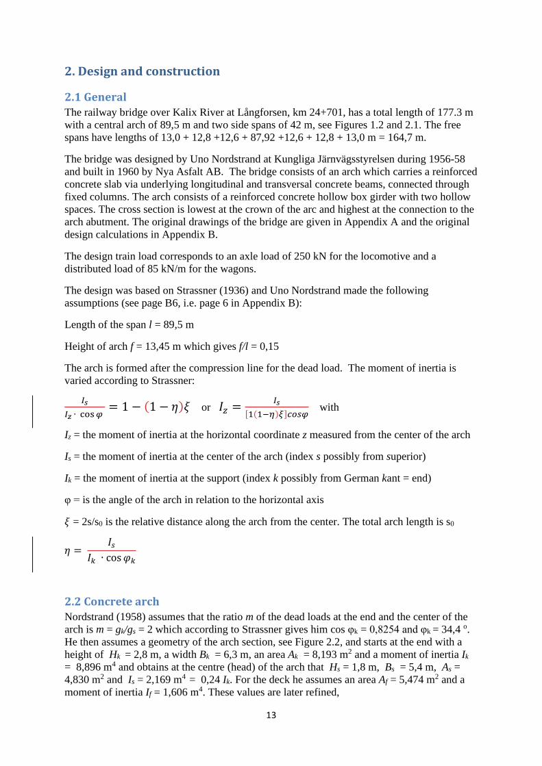
Figure 2.1. The Arch Bridge over Kalix River at Långforsen
To the distributed dead load of the arch is added the load of the deck which enters the arch
through the columns. This is illustrated in Figure 2.3. It results in a horizontal force H = 24,15
MN and a vertical force at each support V = 15,55 MN.
15
Figure 2.2 Typical arch section according to Appendix B, page B9.
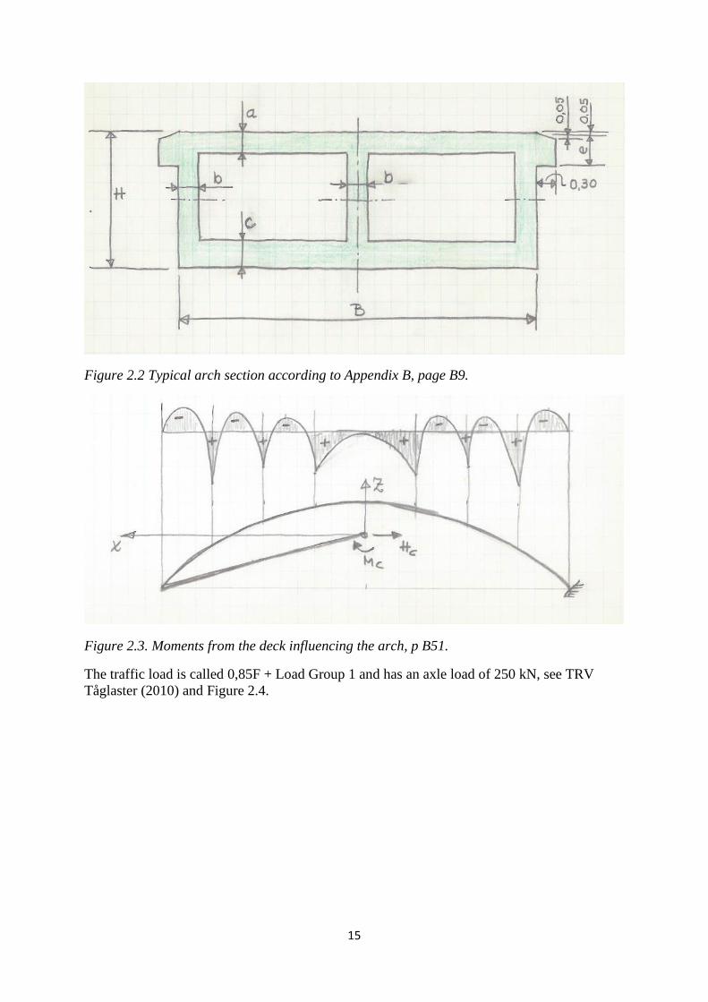
Figure 2.3. Moments from the deck influencing the arch, p B51.
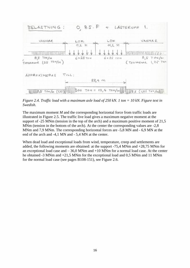
The traffic load is called 0,85F + Load Group 1 and has an axle load of 250 kN, see TRV
Tåglaster (2010) and Figure 2.4.
16
Figure 2.4. Traffic load with a maximum axle load of 250 kN. 1 ton = 10 kN. Figure text in
Swedish.
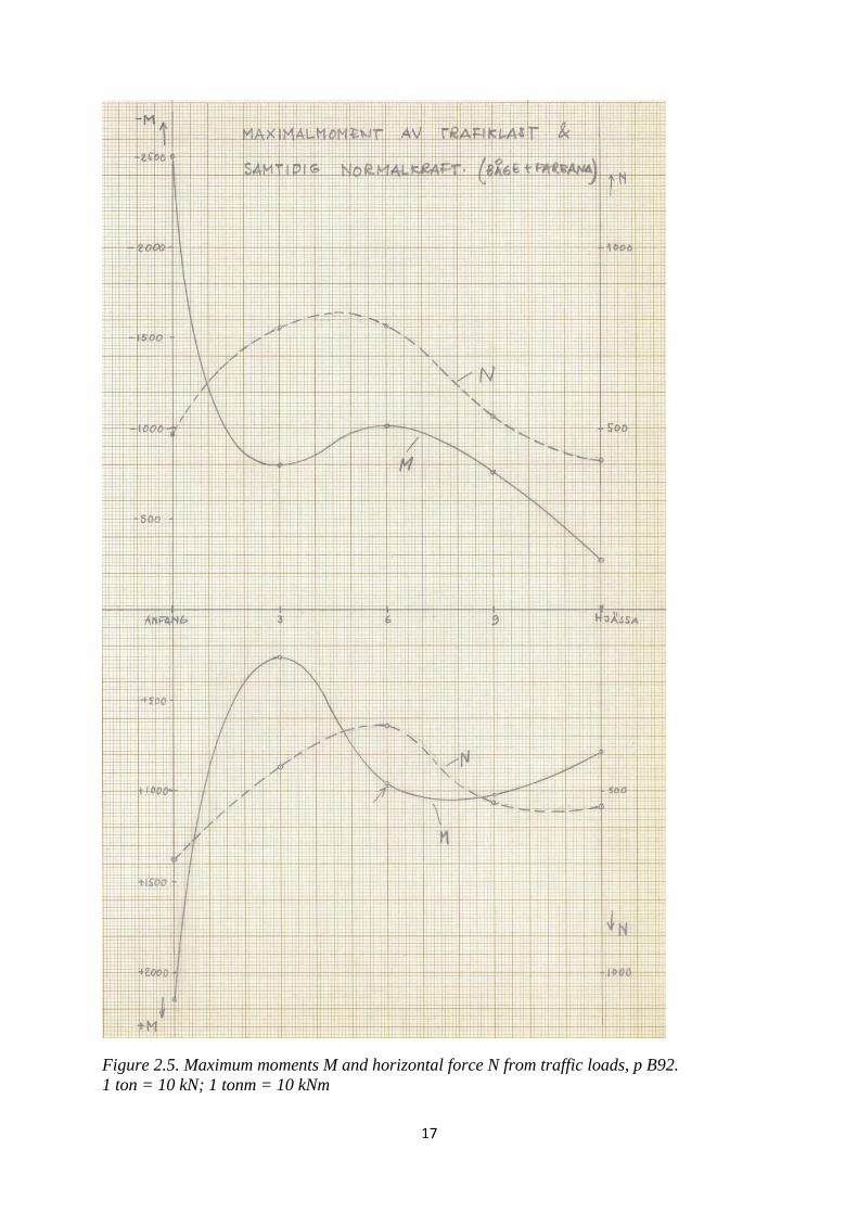
The maximum moment M and the corresponding horizontal force from traffic loads are
illustrated in Figure 2.5. The traffic live load gives a maximum negative moment at the
support of -25 MNm (tension in the top of the arch) and a maximum positive moment of 21,5
MNm (tension in the bottom of the arch). At the center the corresponding values are -2,8
MNm and 7,9 MNm. The corresponding horizontal forces are -5,8 MN and - 6,9 MN at the
end of the arch and -4,1 MN and - 5,4 MN at the center.
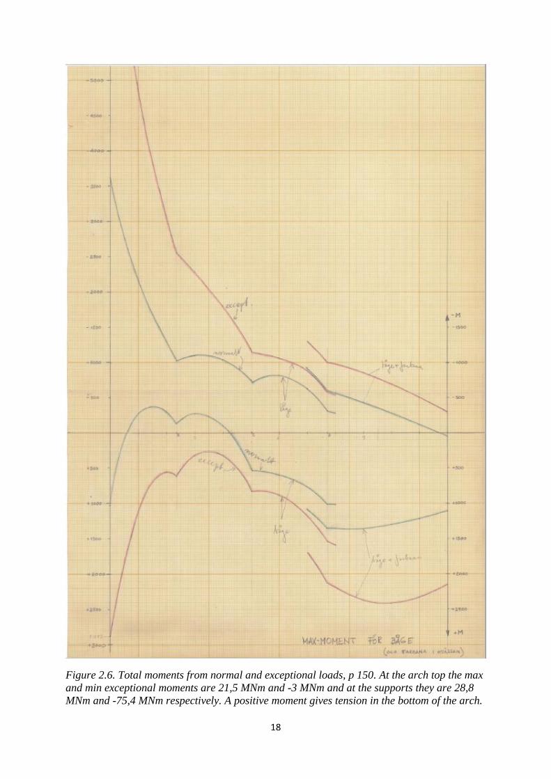
When dead load and exceptional loads from wind, temperature, creep and settlements are
added, the following moments are obtained: at the support -75,4 MNm and +28,75 MNm for
an exceptional load case and – 36,0 MNm and +10 MNm for a normal load case. At the center
he obtained -3 MNm and +21,5 MNm for the exceptional load and 0,5 MNm and 11 MNm
for the normal load case (see pages B108-151), see Figure 2.6.
17
Figure 2.5. Maximum moments M and horizontal force N from traffic loads, p B92.
1 ton = 10 kN; 1 tonm = 10 kNm
18
Figure 2.6. Total moments from normal and exceptional loads, p 150. At the arch top the max
and min exceptional moments are 21,5 MNm and -3 MNm and at the supports they are 28,8
MNm and -75,4 MNm respectively. A positive moment gives tension in the bottom of the arch.
19
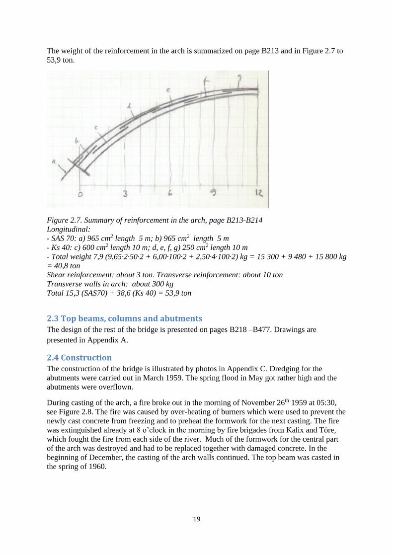
The weight of the reinforcement in the arch is summarized on page B213 and in Figure 2.7 to
53,9 ton.
Figure 2.7. Summary of reinforcement in the arch, page B213-B214
Longitudinal:
- SAS 70: a) 965 cm2 length 5 m; b) 965 cm2 length 5 m
- Ks 40: c) 600 cm2 length 10 m; d, e, f, g) 250 cm2 length 10 m
- Total weight 7,9 (9,65·2·50·2 + 6,00·100·2 + 2,50·4·100·2) kg = 15 300 + 9 480 + 15 800 kg
= 40,8 ton
Shear reinforcement: about 3 ton. Transverse reinforcement: about 10 ton
Transverse walls in arch: about 300 kg
Total 15,3 (SAS70) + 38,6 (Ks 40) = 53,9 ton
2.3 Top beams, columns and abutments
The design of the rest of the bridge is presented on pages B218 –B477. Drawings are
presented in Appendix A.
2.4 Construction
The construction of the bridge is illustrated by photos in Appendix C. Dredging for the
abutments were carried out in March 1959. The spring flood in May got rather high and the
abutments were overflown.
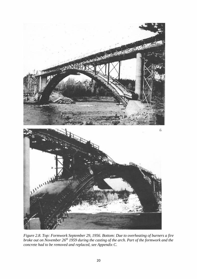
During casting of the arch, a fire broke out in the morning of November 26th 1959 at 05:30,
see Figure 2.8. The fire was caused by over-heating of burners which were used to prevent the
newly cast concrete from freezing and to preheat the formwork for the next casting. The fire
was extinguished already at 8 o’clock in the morning by fire brigades from Kalix and Töre,
which fought the fire from each side of the river. Much of the formwork for the central part
of the arch was destroyed and had to be replaced together with damaged concrete. In the
beginning of December, the casting of the arch walls continued. The top beam was casted in
the spring of 1960.
20
Figure 2.8. Top: Formwork September 29, 1956. Bottom: Due to overheating of burners a fire
broke out on November 26th 1959 during the casting of the arch. Part of the formwork and the
concrete had to be removed and replaced, see Appendix C.
21
3. Geometry and material properties
3.1 Geometry
The main geometry can be seen in Figures 1.2 and 2.1 and in Appendix A. Some essential
data are collected in Table 3.1 below.
Table 3.1. Geometrical properties of arch and deck
Arch [m] Deck [m]
Length, L0 87,92 Height 1,87
Rise, f0 13,706 Width of deck 6,90
Height of crown, h0 1,80 Width of beam 1,00
Height of abutment, hb 2,80
Width of crown 5,40
Width of abutment 6,30
3.2 Material parameters
Concrete of class Btg K400, with a nominal compression strength of 400 kp/cm2 (40 MPa),
was used for everything but the foundations, where Btg K300 was used with nominal
compression strength of 300 kp/cm2 (30 MPa). As reinforcement, steel of quality Ks 40 and
Ss 70 was used with a nominal yield stress of 40 kp/mm2 (400 MPa) and 70 kp/mm2 (700
MPa). respectively
The characteristic concrete material properties were obtained from chapter 13 in BV Bärighet
(2000) according to Table 3.2.
Table 3.2 Nominal Characteristic Material Properties
Concrete Characteristic
Properties
[MPa] Steel
Characteristic Properties
[MPa]
Compression strength, fcck 30,775 Yield stress Ks40 390
Tensile strength, fctk 1,95 Yield stress Ss70 720
Modulus of Elasticity, Ec 32 000 Modulus of Elasticity, Es 200 000
Testing of six drilled out cores from the lower part of the arch was carried out at Luleå
University of Technology in 2009. The cores had a diameter of 95 mm and results according
to Table 3.3 were obtained.
Table 3.3 Tested concrete properties in 2009, compression, fcc, and tensile splitting, fct.
fcc [MPa] fct [MPa]
Sample 1 76,7 Sample 4 1,85
Sample 2 79,8 Sample 5 4,17
Sample 3 65,2 Sample 6 3,77
Mean value, m3 73,9 Mean value 3,26
22
According to BBK 94 (1994) this corresponds to a concrete with fKK ≤ m3 – 4 = 73,9 – 4 =
69,9 MPa, fKK ≤ xmin + 5MPa = 65,2 + 5 =70,2 and fKK ≤ xmin/0,8 = 65,2/0,8 = 81,4 which all
are > 62 MPa of class K80 with characteristic properties according to Table 3.4
Table 3.4. Characteristic Concrete Properties for K80 based on testing
Concrete Characteristic
Properties
[MPa]
Compression strength, fcck 56,5
Tensile strength, fctk 2,65
Modulus of Elasticity, Ec 38,5
This characteristic compression strength value fcck = 56,5 MPa is much higher than the value
30,78 MPa used in an earlier assessment by Leander and Fredriksson (2003, 2004), see
chapter 4.
In the Finite Element Calculations properties according to Table 3.5 were used.
Table 3.5 Properties used in FEM calculations
Property
Modulus of Elasticity, Ec 40 000 MPa
Mass density of concrete, ρc 2,5 t/m3
Mass density of gravel, ρg 2,0 t/m3
The soil deformation modulus was assumed by Nordstrand (1958) to 10 kg/cm3 = 100 GN/m3
(p B390)
23
4. Assessments 2002 -2004
4.1 General
In order to determine if the axle load 330 kN (BV-2000) could be used for the bridge, a
preliminary assessment was made during 2002. This assessment was reviewed by the
consulting company Reinertsen, see Kolster (2002). The programs Strip Step (1971) [see
further Bengtsson & Wolf (1969, 1970) and Lundin (1971)] and Solvia (2000) were used and
it was recommended that a more complete finite element model (FEM) should be applied.
Banverket (The Swedish Rail Administration) then asked the consulting firm Tyréns to carry
out such an improved analysis and an early version of the FEM program Brigade (2012) was
used, Leander-Fredriksson (2003, 2004). A summary of some of the results are presented
below. More details are given in Appendix D.
4.2 Results
The calculations were based on nominal design values, concrete Btg K400 (nominal
compressive strength 400 kp/cm2 = 40 MPa) for the arch, columns, top beams and slab and
Btg K300 (30 MPa) for the foundations. The concrete compressive strength was adjusted
according to BV Bärighet (2000) to a characteristic compressive strength fcck = 30,78 MPa
(corresponding to ≈ C40), a characteristic tensile strength fctk = 1,95 MPa and a modulus of
elasticity Ec = 32 GPa. Characteristic yield stresses used for the steel reinforcement were, fyk =
390 MPa for Ks 40 and fyk = 720 MPa for Ss70.
Several train loads were tested. The different train loads are given in TRV Tåglaster (2010).
The most severe one was tested first. If the section could not stand this load a lesser load was
tried.
BV2000 has an axle load of 330 kN, a line load of 110 kN/m, and an axle distance for bogies
and buffers of 1,6m
UIC 71 has an axle load of 250 kN, a line load of 80 kN/m; and an axle distance for bogies
and buffers of 1,6m
BV-3 has an axle load of 250 kN, a line load of 80 kN/m, an axle distance for bogies of 1,8 m
and for buffers of 3,0m
C3 has an axle load of 200 kN, a line load of 72 kN/m, an axle distance for bogies of 1,8 m
and for buffers of 3,0m.
The results from Leander and Fredriksson (2003, 2004) are summarized in Table 4.1.
24
Table 4.1 Maximum utility ratios (load/capacity) for different parts of the bridge and different
load classes, Leander-Fredriksson (2003, 2004).
Structural Part Section Line Class according to BV Tåglaster
(2009)
Train load class BV 2000 UIC71 BV-3 C3
Axle load (stax), kN 330 250 250 200
Line load, kN/m 110 80 80 72
Distance between
bogies/buffers, m/m
1,6/1,6 1,6/1,6 1,8/3,0 1,8/3,0
Arch Mmin in mid-section 0,92 (1,64*) - - -
Top Beams Mmin where the slab is
connected to the arch
1,087 1,035 1,000 -
Slab, built in Mmax in mid-slab 1,109 0,877 - -
(Slab, simply
supported)
Mmax in mid-slab (2,008) (1,608) (1,135) (0,980)
Cross beam M and V 0,817
*The number in parenthesis is for the case when a full temperature load is acting,
Table 4.1 shows that the arch can carry Load Class BV2000 with an axle load of 330 kN if
the influence of temperature changes is reduced. The most stressed section is the bottom of
the mid-section (head) of the arch. Other sections have lesser strains.
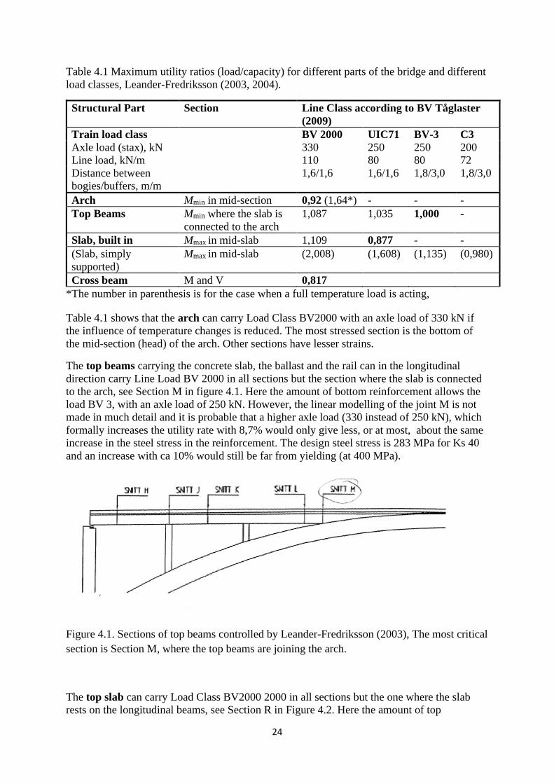
The top beams carrying the concrete slab, the ballast and the rail can in the longitudinal
direction carry Line Load BV 2000 in all sections but the section where the slab is connected
to the arch, see Section M in figure 4.1. Here the amount of bottom reinforcement allows the
load BV 3, with an axle load of 250 kN. However, the linear modelling of the joint M is not
made in much detail and it is probable that a higher axle load (330 instead of 250 kN), which
formally increases the utility rate with 8,7% would only give less, or at most, about the same
increase in the steel stress in the reinforcement. The design steel stress is 283 MPa for Ks 40
and an increase with ca 10% would still be far from yielding (at 400 MPa).
Figure 4.1. Sections of top beams controlled by Leander-Fredriksson (2003), The most critical
section is Section M, where the top beams are joining the arch.
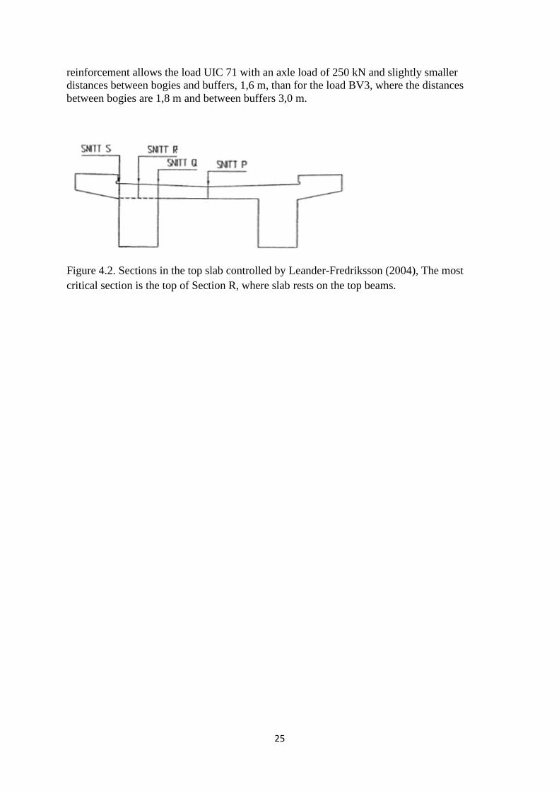
The top slab can carry Load Class BV2000 2000 in all sections but the one where the slab
rests on the longitudinal beams, see Section R in Figure 4.2. Here the amount of top
25
reinforcement allows the load UIC 71 with an axle load of 250 kN and slightly smaller
distances between bogies and buffers, 1,6 m, than for the load BV3, where the distances
between bogies are 1,8 m and between buffers 3,0 m.
Figure 4.2. Sections in the top slab controlled by Leander-Fredriksson (2004), The most
critical section is the top of Section R, where slab rests on the top beams.
26
5. Measurements
5.1 Measurements during 2009
During October, 8-9, 2009, measurements were carried out by Luleå University of
Technology. Material properties were determined. Six cylinders with a diameter of 95 mm
were drilled out from the lower part of the arch as presented in Chapter 3.
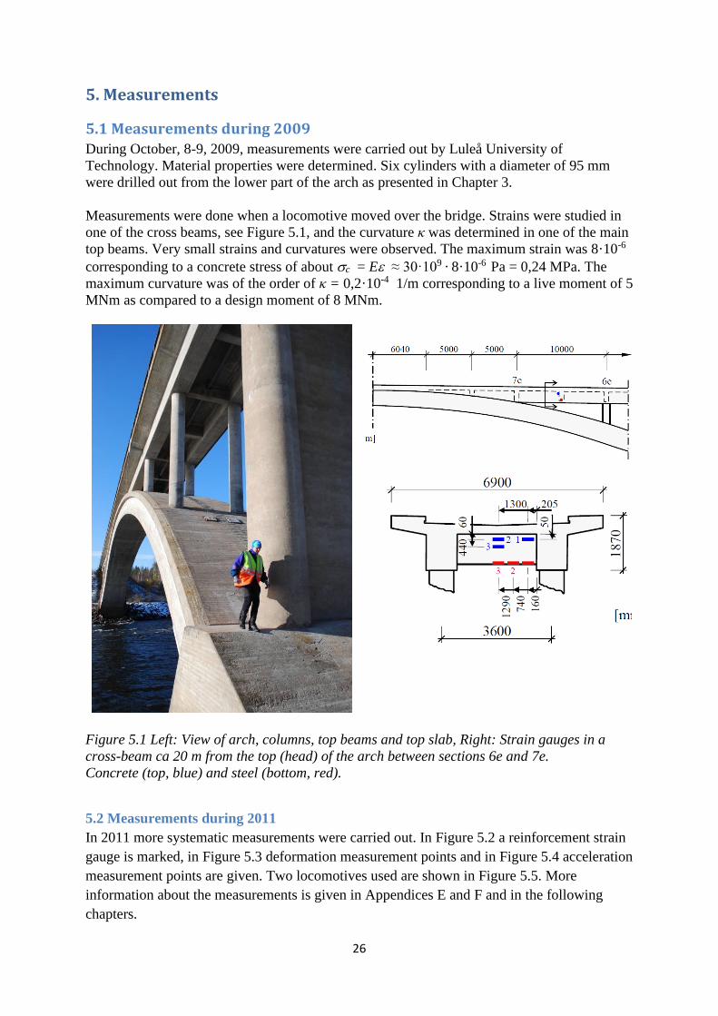
Measurements were done when a locomotive moved over the bridge. Strains were studied in
one of the cross beams, see Figure 5.1, and the curvature κ was determined in one of the main
top beams. Very small strains and curvatures were observed. The maximum strain was 8·10-6
corresponding to a concrete stress of about c = E ≈ 30·109 · 8·10-6 Pa = 0,24 MPa. The
maximum curvature was of the order of κ = 0,2·10-4 1/m corresponding to a live moment of 5
MNm as compared to a design moment of 8 MNm.
Figure 5.1 Left: View of arch, columns, top beams and top slab, Right: Strain gauges in a
cross-beam ca 20 m from the top (head) of the arch between sections 6e and 7e.
Concrete (top, blue) and steel (bottom, red).
5.2 Measurements during 2011
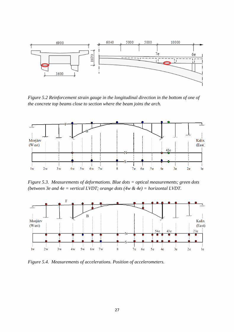
In 2011 more systematic measurements were carried out. In Figure 5.2 a reinforcement strain
gauge is marked, in Figure 5.3 deformation measurement points and in Figure 5.4 acceleration
measurement points are given. Two locomotives used are shown in Figure 5.5. More
information about the measurements is given in Appendices E and F and in the following
chapters.
27
Figure 5.2 Reinforcement strain gauge in the longitudinal direction in the bottom of one of
the concrete top beams close to section where the beam joins the arch.
Figure 5.3. Measurements of deformations. Blue dots = optical measurements; green dots
(between 3e and 4e = vertical LVDT; orange dots (4w & 4e) = horizontal LVDT.
Figure 5.4. Measurements of accelerations. Position of accelerometers.
28
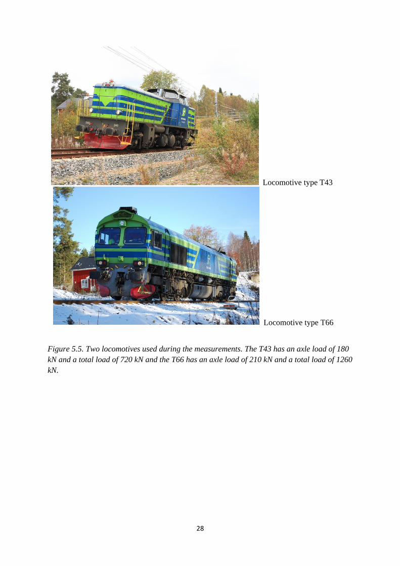
Locomotive type T43
Locomotive type T66
Figure 5.5. Two locomotives used during the measurements. The T43 has an axle load of 180
kN and a total load of 720 kN and the T66 has an axle load of 210 kN and a total load of 1260
kN.
29
6. Finite element models (FEM)
6.1 General
A first beam model was made by Huang Wei in 2009. Its intention was to estimate global
dynamic characteristics before the first measurements were carried out. The model was made
with the program Lusas (2005).
The second model was made by Arto Puurula in 2010 after the first measurements. It was
made in Brigade (2012) and consisted of shell elements in the arch and deck, and beam
elements in the deck beams and columns.
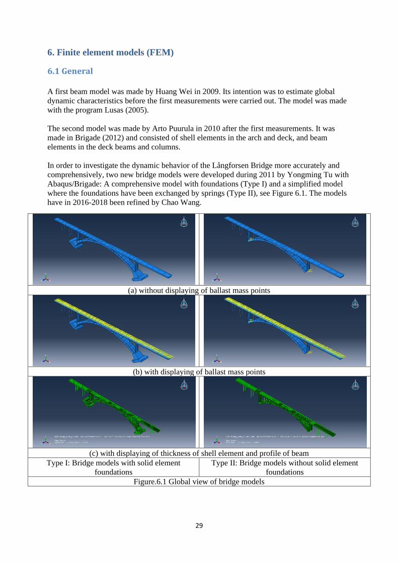
In order to investigate the dynamic behavior of the Långforsen Bridge more accurately and
comprehensively, two new bridge models were developed during 2011 by Yongming Tu with
Abaqus/Brigade: A comprehensive model with foundations (Type I) and a simplified model
where the foundations have been exchanged by springs (Type II), see Figure 6.1. The models
have in 2016-2018 been refined by Chao Wang.
(a) without displaying of ballast mass points
(b) with displaying of ballast mass points
(c) with displaying of thickness of shell element and profile of beam
Type I: Bridge models with solid element
foundations
Type II: Bridge models without solid element
foundations
Figure.6.1 Global view of bridge models
30
6.2 Design of Models
The advantage of the Type I model is that it is closer to the real bridge structure, and the
predicted results from it should be more reliable and closer to the 'real results', but the
disadvantage is that the number of elements is rather high. The number of elements is 93 910
in type I and decreases to 47 438 in type II and the number of variables decreases from 438
800 to 282 808. Both models give very close predictions of eigenfrequencies and deflections.
Both types of models are mainly developed with shell elements except that 16 circular
columns were constructed with beam elements and the two bridge foundations were
constructed with solid elements if the foundations were included in the model. The track was
modelled with point mass/inertia element and flexible boundary conditions with spring
elements (only for the type II model). In the following the type I model will also be named as
the Modal Benchmark model, and type II as the Dynamic Benchmark model)
Beam elements: 16 circular columns, of which 8 are located in the main span, and the other 8
are located in the side spans.
Solid elements: the two arch abutments (end foundations) if they are included in the model
Point mass/Inertia elements: the track including ballast was modeled with equivalent mass
points attached to the top surface of the bridge decks.
Spring elements: for the models without solid element foundations, the translational and
rotational boundary conditions as well as rotational springs as extra flexible rotational
boundary conditions on the bottoms of arch ends and pier bottoms.
Shell elements: all the other parts of the bridge structure except the 16 circular columns and
two arch end foundations
According to the drilled core test, the concrete Young's modulus of the bridge model was set
as 40 GPa. The density of concrete was assumed as 2500 kg/m3, and the density of ballast was
set as 2000 kg/m3. The longitudinal steel rebars embedded in the concrete was considered in
the updated Abaqus/Brigade model using the embedded Abaqus function 'rebar layer' of shell
element according to the reinforcement drawings of the bridge, although the reinforcement
rebars have very small effect on the results for the modal analysis and dynamic responses in
the linear elastic stage of the bridge structure. In the Abaqus/Brigade models, everything was
constructed according to drawings but of course, some simplifications had to be made.
Furthermore, the joints between shell and shell, or beam and shell, or shell and solid, were
overlapped by connecting parts, which were partial sources of modeling error. Fortunately,
parts of such errors were counterbalanced by the over-reinforcement at these joints.
One principle is required when constructing these models: simplifications of the real bridge
should be as few as possible, and the structure simplified should be equivalent to the original
structure (at least mass equivalent, sectional area equivalent and moment inertia equivalent,
etc.). The simplifications and assumptions brought into the FE bridge model in
Brigade/Abaqus could be summarized as follows:
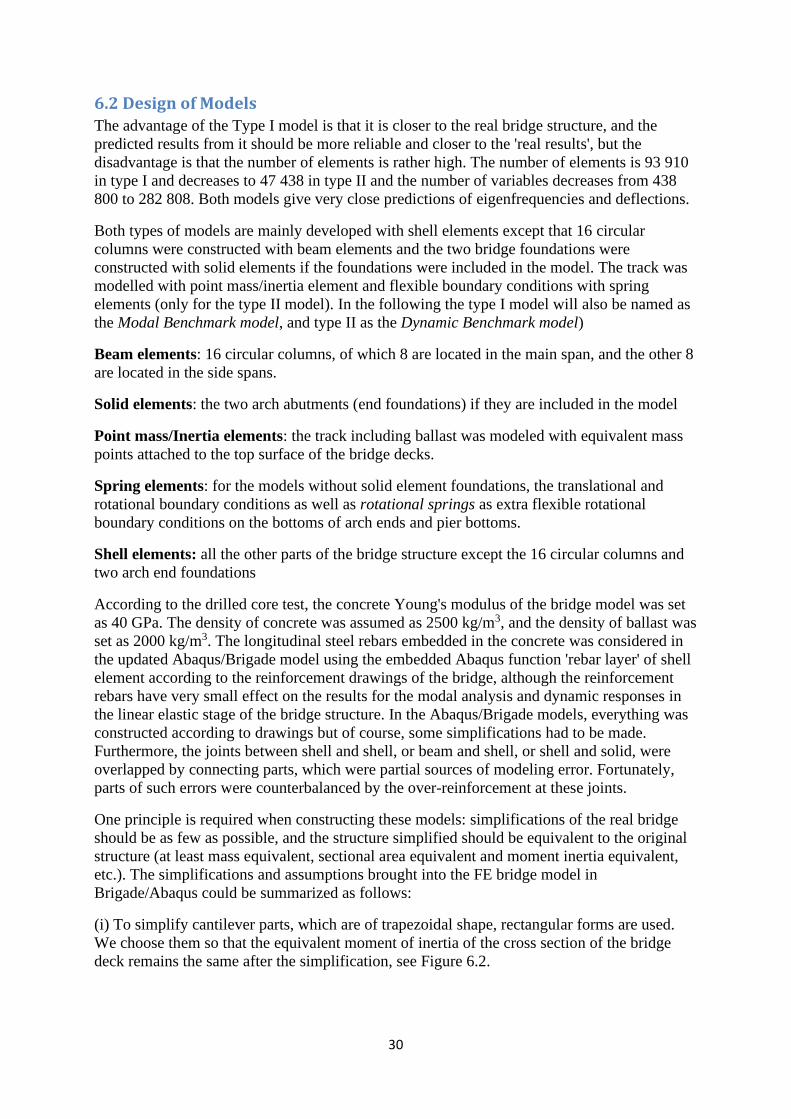
(i) To simplify cantilever parts, which are of trapezoidal shape, rectangular forms are used.
We choose them so that the equivalent moment of inertia of the cross section of the bridge
deck remains the same after the simplification, see Figure 6.2.
31
10000 5000 5000 6040
6e 7e
6900
3600
1870
(a) Standard cross section of bridge
deck before simplification
(b) Standard cross section of bridge
deck after simplification in
Abaqus/Brigade model
Figure 6.2 Standard cross section of the bridge deck
(ii) To assume the discrete reinforcement rebars as a continuous steel layer and to embed
these steel layers into bridge deck, arch and piers.
(iii) Boundary conditions and connections between main span and side spans of the bridge.
Here the models were built in steps:
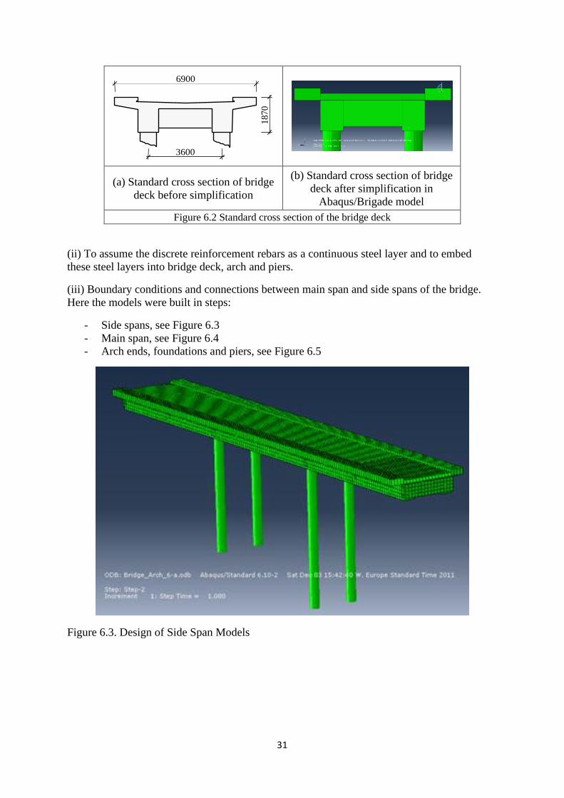
- Side spans, see Figure 6.3
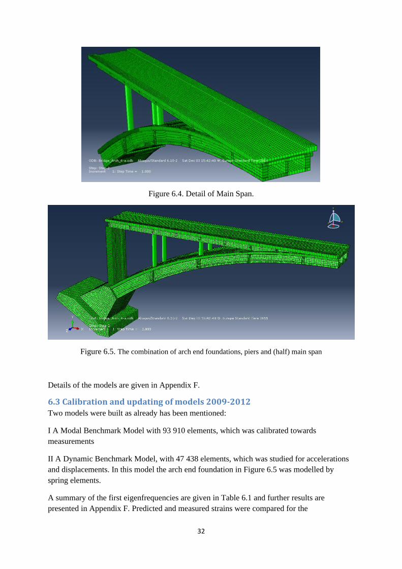
- Main span, see Figure 6.4
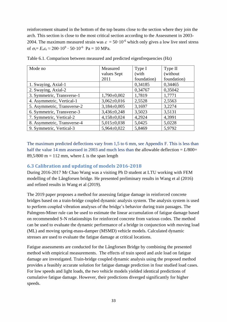
- Arch ends, foundations and piers, see Figure 6.5
Figure 6.3. Design of Side Span Models
32
Figure 6.4. Detail of Main Span.
Figure 6.5. The combination of arch end foundations, piers and (half) main span
Details of the models are given in Appendix F.
6.3 Calibration and updating of models 2009-2012
Two models were built as already has been mentioned:
I A Modal Benchmark Model with 93 910 elements, which was calibrated towards
measurements
II A Dynamic Benchmark Model, with 47 438 elements, which was studied for accelerations
and displacements. In this model the arch end foundation in Figure 6.5 was modelled by
spring elements.
A summary of the first eigenfrequencies are given in Table 6.1 and further results are
presented in Appendix F. Predicted and measured strains were compared for the
33
reinforcement situated in the bottom of the top beams close to the section where they join the
arch. This section is close to the most critical section according to the Assessment in 2003-
2004. The maximum measured strain was = 50·10-6 which only gives a low live steel stress
of s= Ess ≈ 200·109 · 50·10-6 Pa = 10 MPa.
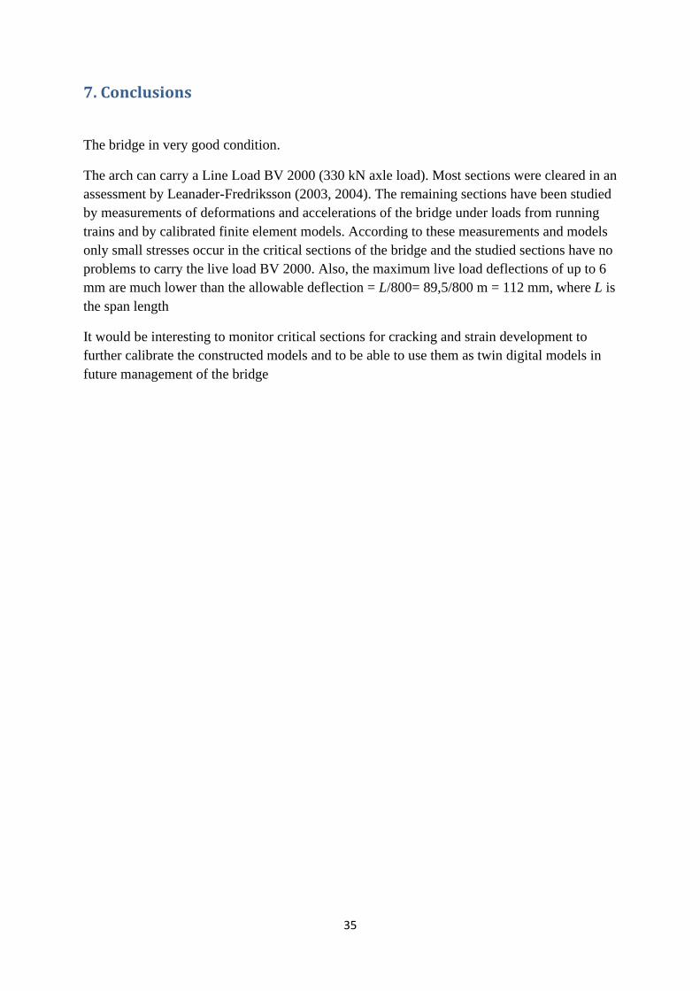
Table 6.1. Comparison between measured and predicted eigenfrequencies (Hz)
Mode no Measured
values Sept
2011
Type I
(with
foundation)
Type II
(without
foundation)
1. Swaying, Axial-1 0,34185 0,34465
2. Swaying, Axial-2 0,34767 0,35042
3. Symmetric, Transverse-1 1,790±0,002 1,7819 1,7771
4. Asymmetric, Vertical-1 3,062±0,016 2,5528 2,5563
5. Asymmetric, Transverse-2 3,184±0,005 3,1697 3,2274
6. Symmetric, Transverse-3 3,436±0,248 3,5023 3,5131
7. Symmetric, Vertical-2 4,158±0,024 4,2924 4,3991
8. Asymmetric, Transverse-4 5,015±0,038 5,0425 5,0228
9. Symmetric, Vertical-3 5,964±0,022 5,8469 5,9792
The maximum predicted deflections vary from 1,5 to 6 mm, see Appendix F. This is less than
half the value 14 mm assessed in 2003 and much less than the allowable deflection = L/800=
89,5/800 m = 112 mm, where L is the span length
6.3 Calibration and updating of models 2016-2018
During 2016-2017 Mr Chao Wang was a visiting Ph D student at LTU working with FEM
modelling of the Långforsen bridge. He presented preliminary results in Wang et al (2016)
and refined results in Wang et al (2019).
The 2019 paper proposes a method for assessing fatigue damage in reinforced concrete
bridges based on a train-bridge coupled dynamic analysis system. The analysis system is used
to perform coupled vibration analyses of the bridge’s behavior during train passages. The
Palmgren-Miner rule can be used to estimate the linear accumulation of fatigue damage based
on recommended S-N relationships for reinforced concrete from various codes. The method
can be used to evaluate the dynamic performance of a bridge in conjunction with moving load
(ML) and moving spring-mass-damper (MSMD) vehicle models. Calculated dynamic
stresses are used to evaluate the fatigue damage at critical locations.
Fatigue assessments are conducted for the Långforsen Bridge by combining the presented
method with empirical measurements. The effects of train speed and axle load on fatigue
damage are investigated. Train-bridge coupled dynamic analysis using the proposed method
provides a feasibly accurate solution for fatigue damage prediction in four studied load cases.
For low speeds and light loads, the two vehicle models yielded identical predictions of
cumulative fatigue damage. However, their predictions diverged significantly for higher
speeds.

34
A main result of the analysis is that there is no fatigue risk for the bridge for axle loads up to
350 kN.
35
7. Conclusions
The bridge in very good condition.
The arch can carry a Line Load BV 2000 (330 kN axle load). Most sections were cleared in an
assessment by Leanader-Fredriksson (2003, 2004). The remaining sections have been studied
by measurements of deformations and accelerations of the bridge under loads from running
trains and by calibrated finite element models. According to these measurements and models
only small stresses occur in the critical sections of the bridge and the studied sections have no
problems to carry the live load BV 2000. Also, the maximum live load deflections of up to 6
mm are much lower than the allowable deflection = L/800= 89,5/800 m = 112 mm, where L is
the span length
It would be interesting to monitor critical sections for cracking and strain development to
further calibrate the constructed models and to be able to use them as twin digital models in
future management of the bridge
36
References
Ahlberg, Sven Olof och Spade, Bengt (2001). Våra broar – en kulturskatt. (Our Bridges. A
cultural hertage. In Swedish).Borlänge: Banverket och Vägverket. ISBN 91-88250-43-1, 446
sid.
Abaqus (2012). A unified FEA product suite offering solutions for engineering problems
covering a vast spectrum of industrial applications. In the automotive industry engineering
work groups are able to consider full vehicle loads, dynamic vibration, multibody systems,
impact/crash, nonlinear static, thermal coupling, and acoustic-structural coupling using a
common model data structure and integrated solver technology, see
http://www.3ds.com/products/simulia/portfolio/abaqus/overview/ (Read 12 July 2012)
Asplund, Sven Olov (1966). Structural Mechanics: Classical and Matrix Methods, Prentice-
Hall, Inc., Englewood Cliffs, N.J., 1966, xiii + 474 pp.
Bagge, Niklas (2017). Structural Assessment Procedures for Existing Concrete Bridges.
Experiences from failure tests of the Kiruna Bridge. Doctoral Thesis, Luleå University of
Technology, ISBN 978-91-7583-879-3, 310 pp. http://ltu.diva-portal.org/
Bagge, Niklas; Popescu, Cosmin &; Elfgren, Lennart (2018). Failure tests on concrete
bridges: Have we learnt the lessons? Structure and Infrastructure Engineering, 14(3), 292–319
BBK 94 (1994). Boverkets handbok om Betongkonstruktioner, Band 1 Konstruktion.
Boverket, Karlskrona 1994, 185 sid. ISBN 91-7332-686-0. Band 2 Material, Utförande och
Kontroll. Boverket, Karlskrona 1994, 116 sid. ISBN 91-7332-687-9.
BBK 04 (2004). Boverkets handbok om betongkonstruktioner (2004). (The Swedish Building
Administration’s Handbook on Concrete Structures. In Swedish). Stockholm, Sweden: The
Swedish Building Administration, Division of Buildings, August 2004.
Bengtsson, Å and Wolf, J.P. (1969). Strip (structural integrated programs) user’s manual
Step-2 Plane Member Systems. In Swedish: Nordisk ADB AB, Stockholm, in German:
Digital AG, Zürich. Cited from Bengtsson & Wolf (1970). The program has later been
developed for PC applications by Ingenjörsfirma Åke Bengtsson AB, Stockholm.
Bengtsson, Åke; Wolf, John P (1970). Optimum integer number and position of several
groups of prestressing tendons for given concrete dimensions. Computers & Structures,
Elsevier, Vol. 3, No 4, July 1973, Pages 827-848
Bennitz, Anders (2006). Dynamic Behavior of the Vindel River Railway Bridge –
Measurements and Evaluation for Displacements and Eigenfrequencies. Div. of Structural
Engineering, Luleå University of Technology. Master of Science Thesis 2006:154 CIV., 121
pp. http://www.diva-portal.org/smash/get/diva2:1025054/FULLTEXT01.pdf
Blanksvärd, Thomas (2009). Strengthening of concrete structures by the use of mineral based
composites: system and design models for flexure and shear. Doctoral Thesis.Luleå
University of Technology, ISBN 978-91-86233-23-5, 156 pp. Available from
http://ltu.diva-portal.org/smash/get/diva2:999667/FULLTEXT01.pdf (Read July 22, 2019)
37
Brigade (2012). A FEM program for Bridge Analysis based on Abaqus, see
http://www.scanscot.com/products/brigadestandard/ (Read 12 July 2012)
Brincker, Rune & Ventura, Carlos (2015). Introduction to Modal Analysis, Wiley, ISBN: 978-
1-119-96315, 372 pp. web: www.brinckerdynamics.com
Brown, David, J. (1998). Bridges. Three thousand years of defying nature. London: Mitchel
Beazley, 1993, 1998, 176 pp, ISBN 1-840001-38-0
BV Bärighet (2000). Bärighetsberäkning av järnvägsbroar. (Assessment of Railway Bridges.
In Swedish) Handbok BVH 583.11. Banverket , CB, Borlänge 2000-03-01, 108 pp + 6 app.
Earlier version 1996-07-01, 60 pp.
BV Bärighet (2005). Bärighetsberäkning av järnvägsbroar (Assessment of Railway Bridges.
In Swedish). Handbok BVS 583.11. Banverket, CB, Borlänge 2005-06-01, 108 pp + 9 app.
Present versions see TRV Capacity Rules (2017) and TRV Capacity Advice (2017)
Carolin, Anders (2003). Carbon Fibre Reinforced Polymers for Strengthening of Structural
Members. Doctoral Thesis 2003:18. Luleå University of Technology, 190 pp. Available from
https://ltu.diva-portal.org
Coric, Ibrahim; Täljsten, Björn; Blanksvärd, Thomas; Sas, Gabriel; Ohlsson, Ulf & Elfgren,
L. (2018). Railway Bridges on the Iron Ore Line in Northern Sweden– From Axle Loads of
14 to 32,5 ton. In IABSE Conference 2018 – Engineering the Past, to Meet the Needs of the
Future, June 25-27 2018, Copenhagen, Denmark: IABSE Reports, Vol 111.
Cremona, Christian (2011). Structural Performance. Probability based assessment. London
and New York: ISTE-Wiley, 448 pp, ISBN 978-1-84821-236-7.
Elfgren, Lennart; Enochsson, Ola; Puurula, Arto; Nilimaa, Jonny and Töyrä, Björn (2009).
Preliminary Assessment of Finnish Railway Bridges. Railway Infrastructure Upgrading with
Increase of Axle Loads from 25 to 30 tonnes on the Line Tornio – Kolari. A Comparison with
Swedish Railway Bridges on the Lines Luleå – Narvik and Haparanda – Boden. Luleå
Railway Research Centre, JVTC, and Division of Structural Engineering, Luleå University of
Technology, January 2009, 39 pp. http://www.diva-
portal.se/smash/get/diva2:995852/FULLTEXT01.pdf (Read2019-07-22)
Elfgren, Lennart (2015). Fatigue Capacity of Concrete Structures: Assessment of Railway
Bridges. Research Report, Structural Engineering, Luleå University of Technology, 103 pp.
http://ltu.diva-portal.org/
Elfgren, Lennart; Täljsten, Björn; Blanksvärd, Thomas; Sas, Gabriel; Nilimaa, Jonny; Bagge,
Niklas; Tu, Yongming; Puurula, Arto; Häggström, Jens & Paulsson, Björn (2018). Load-
testing used for quality control of bridges. In Quality Specifications for Roadway Bridges.
Workshop of COST TU 1406, Wroclaw, March 1-2, 2018, 6pp. Available at http://ltu.diva-
portal.org/smash/get/diva2:1177454/FULLTEXT01.pdf. (Read 2019-07-30)
Elfgren, Lennart; Täljsten, Björn and Blanksvärd. Thomas (2019). Load Testing as Part of
Bridge Management in Sweden. Chapter 11, pp 333-346, in “Load Testing of Bridges: Proof
38
load Testing and the Future of Load Testing”, Volume Editor Eva O.L. Landsoght. Series:
Structures and Infrastructures, Vol. 13, Series Editor Dan M. Frangopol, CRC Press/Balkema,
Taylor & Francis Group, London/Leiden, ISBN 978-0-367-21083-0, 378 pp.
Enochsson, Ola; Hejll, Arvid; Nilsson, Martin; Thun Håkan; Olofsson, Thomas; and Elfgren
Lennart (2002). Bro över Luossajokk. Beräkning med säkerhetsindexmetod. Böjdragkapacitet
i överkant i mittsnittet i korta spannet. (Bridge over Luossajokk. Calculations with a safety
index method. Bending capacity in the midsection of the short span.In Swedish). Teknisk
rapport 2002:06. Avdelningen för Konstruktionsteknik, Luleåtekniska universitet. Luleå
2002. 92 pp. https://ltu.diva-portal.org (Read 2019-07-22).
Enochsson, Ola; Puurula, Arto & Elfgren, Lennart (2004). Beräkning av betongbroars
bärförmåga. Interaktion mellan tvärkraft, vridmoment och böjning i Källösundsbron
(Assessment of the Load Carrying Capacity of Concrete Bridges. Interaction between torsion,
shear and bending in the Källösund Bridge. In Swedish) Technical Report 2004:15, Luleå:
Division of Structural Engineering, Luleå University of Technology, 116 p.
http://ltu.diva-portal.org/smash/get/diva2:996544/FULLTEXT01.pdf (Read 2019-07-22)
Enochsson, O., Puurula, A., Stenlund, A., Thun, H., Nilsson, M., Täljsten, B., Olofsson, T.&
Elfgren, L. (2005). Condition Assessment of Concrete Bridges in Sweden. In “Concrete repair,
rehabilitation and retrofitting” edited by Alexander, M. G., Beushausen, H.-D., Dehn, F.
&Moyo, P. Taylor and Francis Group, pp 257-259.ISBN 0-415-39656-5.
Enochsson, Ola; Elfgren, Lennart; Kronborg, Anders & Paulsson, Björn (2008). Assessment
and monitoring of an old railway steel truss bridge in northern Sweden. In “Bridge
Maintenance, Safety, Management, Health Monitoring and Informatics” edited by Hyun-Moo
Koh and Dan M. Frangopol. Leiden: CRC Press/Balkema, Taylor & Francis Group, ISBN
978-0-415-46844-2, Abstract p 701 + full version on CD pp 3617-3624.
Enochsson, Ola; Elfgren, Lennart; Johansson, Håkan; Ojanen, Johan; Emborg, Mats (2010).
Tillståndsbedömning av järnvägsbro över Byske älv vid Myrheden, Bandelen Bastuträsk –
Nyfors, km 1031+937 (Assessment of the Railway Bridge over Byske River at Myrheden on
the Line Bastuträsk – Nyfors. In Swedish). Division of Structural Engineering. Luleå
University of Technology.21pp. + Appendix A. Design and Construction, 112 pp; Appendix
B. Assessment 1994, 3 pp; and Appendix C. Inspection 2009, 14 pp. https://ltu.diva-portal.org
Enochsson, Ola; Sabourova, Natalia; Emborg; Mats & Elfgren, Lennart (2011). Gruvvägsbron
i Kiruna. Deformationskapacitet. (The Mine bridge in Kiruna. Deformation Capacity. In
Swedish), Teknisk Rapport, Div. of Structural Engineering, Luleå University of Technology,
108 pp. http://ltu.diva-portal.org/smash/get/diva2:997801/FULLTEXT01.pdf (Read 2019-07-
24)
Fernández Troyano, Leonardo (2003). Bridge Engineering. A global perspective. London:
Thomas Telford 2003, (First Spanish Ed 1999), 775 pp, ISBN 0-7277-3215-3.
fib B22 (2003). Monitoring and safety evaluation of existing concrete structures. Lausanne:
The International Federation for Structural Concrete, fib, Bulletin 22, 297 pp, ISBN 2-88394-
062-2
fib B62 (2012). Structural Concrete. Textbook on behaviour, design and performance. 2nd
Ed., Volume 5. Through-life care and management of concrete structures – assessment,
39
protection, repair and strengthening. International Federation for Structural Concrete (fib),
Lausanne, January 2012, 462 pp, ISBN 978-2-88394-102-1.
fib Model Code (2010). fib model Code 2010, First Complete Draft – Volume 1 and 2. fib
Bulletins 55 and 56. International Federation of Structural Concrete, Lausanne 2010, ISBN
978-2-88394-095-6 and 978-2-88394-096-3.
Forsberg, Thomas, Grip, Niklas, & Sabourova, Natalia (2013). Non-iterative calibration for
accelerometers with three non-orthogonal axes, reliable measurement setups and simple
supplementary equipment. Measurement Science and Technology, 24(3). DOI: 10.1088/0957-
0233/24/3/035002 http://ltu.diva-portal.org/smash/get/diva2:976957/FULLTEXT01.pdf
(Read 2019-08-01)
Frýba, L. (1996). Dynamics of Railway Bridges. London: Thomas Telford
Graf, Bernhard (2002). Bridges that Changed the World. Munich: Prestel, 126 pp, ISBN 3-
7913-3400-X.
Grip, N., Sabourova, S., (2011). Simple non-iterative calibration for triaxial accelerometers.
Measurement Science and Technology, Vol 22, No 12, 12 pp.
Grip, Niklas (2013). Inte bara broar. Vibrationsanalys för tillståndsbedömning (Not only
bridges. Vibration Analysis for Assessment of Buildings, In Swedish). SBUF id:12513,
Svenska Byggbranschens utvecklingsfond, 91 pp.
http;//vpp.sbuf.se/Public/Documents/ProjectDocuments
http://ltu.diva-portal.org/ (Read 2019-08-01)
Grip, Niklas; Sabourova, Natalia; Tu, Yongming & Elfgren, Lennart (2016). Vibrationsanalys
för tillståndsbedömning av byggkonstruktioner. (Vibration Analysis for Assessment of
Buildings, In Swedish with a summary and Appendices in English). SBUF id:13010, Svenska
Byggbranschens utvecklingsfond, 34 pp. + Apendices.
http;//vpp.sbuf.se/Public/Documents/ProjectDocuments
http://ltu.diva-portal.org/ (Read 2019-08-01)
Gustafsson, Stanley and Müllersdorf, Uno (1961). Bågar. (Arches. In Swedish) Chapter 164
in Bygg, Vol 1, Part 1 General, 3rd Ed., Edited by Wilhelm Tell, Stockholm: Byggmästarens
Förlag, pp 670-684. In the 1st Ed from 1947-53 the chapter was authored by Salomon
Kasarnowsky.
He, G. J.; Bennitz, A.; Enochsson, O.; Elfgren, L.; Paulsson, B.; Töyrä, B.; Olofsson, P. and
Kronborg, A. (2006). Numerical modeling and dynamic behavior of a railway concrete bridge
over the Vindel River in Sweden. Proc 3rd Int. Conf. on Bridge Maintenance, Safety and
Management (IABMAS’06), Porto, Portugal, 16-19 July 2006. Taylor & Francis Group,
London, Abstract pp 327-328. (Full paper P-104, 8 p, on attached CD). ISBN 0 415 40315 4.
He, G., Zou, Z., Enochsson, O., Bennitz, A., Elfgren, L., Kronborg, A., Töyrä, B., and
Paulsson, B. (2008). Assessment of railway concrete arch bridge by numerical modelling and
measurements.In “Bridge Maintenance, Safety, Management, Health Monitoring and
Informatics” edited by H.-M.Koh and D. M. Frangopol. Leiden: CRC Press/Balkema, Taylor
& Francis Group, ISBN 978-0-415-46844-2, Abstract p 722 + full version on CD pp 3733-
3742.
40
Huang, Zheng; Tu, Yongming; Grip, Niklas; Sabourova, Natalia; Bagge, Niklas; Blanksvärd,
Thomas; Ohlsson, Ulf & Elfgren, Lennart (2016). Modelling of Damage and its use in
Assessment of a Prestressed Concrete Bridge. In “Challenges in Design and Construction of
an Innovative and Sustainable Built Environment”. Proceedings IABSE Congress, Stockholm,
21-23 September, 2016. International Association for Bridges and Structural Engineering
(IABSE), Zürich. ISBN 978-3-85748-144-4, pp 2093-2108. A fuller version as a Research
Report, Division of Structural Engineering, Lulea University of Technology, 22 pp. Available
at http://ltu.diva-portal.org/
Häggström, Jens and Martinsson, Frida (2009). Numerical Modelling of the Vindel River
Railway Bridge – Upgrade of a Finite Element Model from Dynamic Measurements. Master's
Thesis 2009:152 ISSN 1402-1617, Division of Structural Engineering, Luleå University of
Technology, 100 pp. http://www.diva-portal.org/smash/get/diva2:1031858/FULLTEXT01.pdf
(Read 2019-07-22)
Häggström, Jens (2016). Evaluation of the Load Carrying Capacity of a Steel Truss Railway
Bridge: Testing, Theory and Evaluation. Lic. Thesis, Luleå University of Technology, 142 pp.
http://ltu.diva-portal.org/
Häggström, Jens; Blanksvärd, Thomas; Täljsten, Björn (2017). Bridge over Åby River –
Evaluation of full-scale testing. Research Report, Div. of Structural Engineering, Luleå
University of Technology, 180 pp. http://ltu.diva-portal.org/
Järnväg.net (2019): Historia Haparandabanan (In Swedish)
http://www.jarnvag.net/banguide/boden-haparanda (Read 2019-07-22) See also:
https://sv.wikipedia.org/wiki/Haparandabanan
Kolster (2002). Bro över Kalix älv vid Långforsen, Morjärv – Kalixborgs bruk, km 24+703.
Granskningsrapport av Bärighetsberäkning. (Comments on Assessment of the Bridge at
Långforsen. In Swedish). Reinertsen Projekt nr 20020760, 4 pp.
Kurrer, Karl-Eugen (2008). The History of the Theory of Structures. From Arch Analysis to
Computational Mechanics. Berlin: Ernst & Sohn, 848 pp. ISBN 978-3-433-01838-5
Larsson, Ulf (1997). Brobyggaren. Otto Linton, byggnadskonsten och dess profession i
Norden under första delen av 1900-talet. (Bridge Builder Otto Linton.Building in
Scandinavia during the first part of the 20th century.In Swedish with an English
Summary).Stockholm: Carlsson Bokförlag, 398 pp, ISBN 91 7203 2022.
Leander, John and Fredriksson, Rune (2003). Morjärv-Kalix, Järnvägsbro över Kalix älv vid
Långforsen, km 24+701 (Assessment of the Bridge at Långforsen). Tyréns Projekt nummer
204609, 11 pp + Appendix with calculations, some 200 pp.
Leander, John and Fredriksson, Rune (2004). Morjärv-Kalix, Järnvägsbro över Kalix älv vid
Långforsen, km 24+701 Bärighetsberäkning; farbaneplatta (Assessment of the Bridge at
Långforsen, Concrete Deck). Tyréns Projektnummer 204644, 10 pp + Appendix with
calculations, some 100 pp.
Lorentsen, Mogens (1966). Bågbroar (Arch Bridges. In Swedish). Chapter 934 in Bygg, Vol
6, Part 9 Civil Engineering, 3rd Ed., Edited by Wilhelm Tell, Stockholm: Byggmästarens
Förlag, pp 386-422.
41
Lundin, Per, Editor (2006). Databehandling vid Väg- och vattenbyggnadsstyrelsen/Vägverket
1957–1980. Transskript av ett vittnesseminarium vid Tekniska Museet i Stockholm den 22
mars 2006 (Computational Methods used at the Swedish National Road Administration 1957–
1980. In Swedish). Working paper from the Div. of History of Science and Technology, KTH,
Stockholm, TRITA-HST 2007/2, 42 pp. https://www.diva-
portal.org/smash/get/diva2:12336/FULLTEXT01.pdf
(Read 2019-07-24)
LUSAS (2005). Powerful FE technology for specialist application, Modeller User Manual,
United Kingdom
MAINLINE (2011). A European Community 7th Framework Program research project with
the full title: MAINtenance, renewaL and Improvement of rail transport iNfrastructure to
reduce Economic and environmental impacts. Research Project 2011-2014 with 19 partners.
Grant agreement 285121, SST.2011.5.2-6. Dr. Björn Paulsson, UIC/Trafikverket acted as
Project Coordinator, see www.mainline-project.eu
Nilimaa, Jonny (2015). Concrete bridges: Improved load capacity. (Ph.D. Thesis),
Luleå University of Technology, Luleå, Sweden, ISBN 978-91-7583-345-3, 176 pp.
http://ltu.diva-portal.org/
Nilsson, Martin; Ohlsson, Ulf och Elfgren, Lennart (1999). Partialkoefficienter för hållfasthet
i betongbroar längs Malmbanan. (Partial coefficients for concrete strength in bridges on
Malmbanan. In Swedish). Teknisk Rapport 1999:03, Avd för konstruktionsteknik, Luleå tekn.
universitet, 38 + 38 sid. Can be downloded from
http://ltu.diva-portal.org/smash/get/diva2:994939/FULLTEXT01.pdf (Read 2019-07-22)
Nordstrand, Uno (1958). Dimensioneringsberäkningar (Design Calculations. In Swedish)
Bågbro över Kalix älv vid Långforsen, km 24 + 703, SJ Kungliga Järnvägsstyrelsen, 477 sid,
see Appendix B.
Paulsson, Björn & Töyrä, Björn, project leaders (1996). 30 ton på Malmbanan. (30 ton Axle
Load on the Iron Ore Line. In Swedish). ). In the project several studies were carried out
regarding different parts of the infra-structure. The studies are presented in a summary report
and in seven detailed reports. A similar study was carried out by Jernbaneverket in Norway
for the line Riksgränsen – Narvik.
Summary Report of the following reports:
- 3.0 Infrastruktur - Broar och Geoteknik (Bridges and Geotechnology. Summary Report in
Swedish), 34 pp
- 3.1 Infrastruktur - Inventering broar (Inventory of Bridges), 22 pp + 8 appendices
- 3.2 Infrastruktur - Beräkningar och konsekvenser – broar (Bridges – Calculations), 48 pp +
10 appendices
- 3.3 Infrastruktur - Forsknings- och utvecklingsprojekt avseende betongbroars bärighet
(Research Project on Bridges) 51 pp + 5 appendices
- 3.4 Infrastruktur - Geoteknisk inventering (Geotechnical Inventroy), 53pp. + 14 app.
- 3.5 Infrastruktur – Stabilitetsutredning (Stability of Embankments), 19 pp + 5 app
- 3.6 Infrastruktur - FoU Beräkningsmodell för grundläggning på torv Fondations on Peat), 53
pp + 11 app.
- 3.7 Infrastruktur - Geotekniska åtgärder Geotechnical Actions) 50 pp + 5 app.
42
In Norway a corresponding study was made by Jernbaneverket on Ofotenbanan from
Riksgränsen to Narvik:
- 3.11 Infrastruktur -Kontrollberegning av stål- og steinhvelvbruer. (Steel and arch bridges. In
Norwegian) 8 pp + 22 App. Jernbaneverket, December 1996.
-3.12 Infrastruktur -Kontrollberegning av Nordalsbruene (Nordal bridges). 6 pp + 7 App.
Jernbaneverket,
Paulsson, Björn; Töyrä, Björn; Elfgren, Lennart; Ohlsson, Ulf; Danielsson, Georg; Johansson,
Håkan and Åström, Lars (1996). 30 ton på Malmbanan. Rapport 3.3 Infrastruktur.
Forsknings- och utvecklingsprojekt avseende betongbroars bärighet (Static field tests on four
trough bridges and a laboratory fatigue test on one trough bridge. In Swedish). Banverket och
Luleå tekniska universitet, 51pp + 5 Appendices.
Paulsson, Björn; Töyrä, Björn; Elfgren, Lennart; Ohlsson, Ulf and Danielsson, Georg (1997).
Increased Loads on Railway Bridges of Concrete. Advanced Design of Concrete Structures
(Ed. by K Gylltoft et al), Cimne, Barcelona, 1997. pp 201-206 (ISBN 84-87867-94-4).
Paulsson, Björn (1998). Assessing the track costs of 30 tonne axle loads. Railway Gazette
International, volume 154, no 11, 1998. pp 785-788 (3 pages). See also Lundén, Roger
(1998): LKAB invests in 30 tonne axle loads. Railway Gazette International, volume 154, no
9, 1998. pp 585-588 (3 pages).
Paulsson, Björn; Bell, Brian; Schewe, Britta; Jensen, Jens Sandager; Carolin, Anders &
Elfgren, Lennart (2016). Results and Experiences from European Research Projects on
Railway Bridges. 19th IABSE Congress Stockholm, 2570-2578. ISBN 978-2-85748-144-4.
http://ltu.diva-portal.org/
Puurula, Arto (2004). Assessment of Prestressed Concrete Bridges Loaded in Combined
Shear, Torsion and Bending. Licentiate Thesis 2004:43, Luleå: Division of Structural
Engineering, Luleå University of Technology. https://ltu.diva-portal.org
Puurula, Arto (2012). Load-carrying capacity of a strengthened reinforced concrete bridge.
Non-linear finite element modeling of a test to failure. Assessment of train load capacity of a
two span railway trough bridge in Örnsköldsvik strengthened with bars of Carbon Fibre
Reinforced Polymers (CFRP). Ph D Thesis, Div. of Structural Engineering, Luleå University
of Technology, 2012, 332 pp, ISBN 978-91-7439-433-7. Can be downloaded from
http://ltu.diva-portal.org/smash/get/diva2:999887/FULLTEXT01.pdf (Read 2019-07-22)
SB (2008): Sustainable Bridges – Assessment for Future Traffic Demands and Longer Lives,
A European Integrated Research Project during 2003-2008 within FP6, No TIP3-CT-2003-
001653, see https://ltu.diva-portal.org . Four guidelines have been prepared:
- Inspection and Condition Assessment (SB-ICA), 259 pp;
- Load and Resistance Assessment of Railway Bridges (SB-LRA), 428 pp;
- Guideline for Monitoring of Railway Bridges (SB-MON), 93 pp; and
- Guide for use of Repair and Strengthening methods for Railway Bridges (SB-STR), 139 pp.
Background documents with state-of-art reports, analytical and numerical analyses and test
results are also provided.
SB 7.3 (2008). Field Test of a Concrete Bridge in Örnsköldsvik, Sweden. Prepared by
Sustainable Bridges – a project within EU FP6. 63 + 333 pp. Available from: https://ltu.diva-
portal.org
43
Solvia (2000) A FEM program: SOLVIA-PRE for stress analysis and SOLVIA-POST for
post-processing, version 99.0. SOLVIA Engineering AB, Report SE 99-1 & 99-3, Västerås,
Sweden 2000.
Stenlund, Anders (2008). Load Carrying Capacity of Bridges. Three case studies of Bridges
in northern Sweden where Probabilistic Methods have been used to Study effects of
Monitoring and Strengthening. Division of Structural Engineering, Luleå University of
Technology, Licentiate Thesis 2008:18, 289 pp. Available from https://ltu.diva-portal.org
Strassner, Albert (1937). Nuere Methoden zur Statik der Rahmentragwerke und der
elastischen Bogenträger: mit besonderer Berücksichtigung der Anwendung in der Praxis des
Eisenbetonbaues (New Methods for Static Calculations of Frames and elastic Arches. In
German), Berlin: Wilhem Ernst und Sohn, Band 1-2. 1st Ed 1916 and several later Eds. Cited
from Gustafsson and Müllersdorf (1961).
Strip Step (1971). Early FEM program developed by Ingenjörsfirma Åke Bengtsson AB and
extensively used by Swedish consultants. There are two versions StripStep 2 and StripStep 3
for 2- and 3-dimensional structures. Its development is presented in Lundin (2006), see also
Bengtsson & Wolf (1969, 1970).
Thun, Håkan; Ohlsson, Ulf and Elfgren, Lennart (1999). Betonghållfasthet i järnvägsbroar på
Malmbanan. Karakteristisk tryck- och draghållfasthet för 20 broar mellan Luleå och
Gällivare. (Concrete Strength in Railway Bridges on Malmbanan. Tensile and Compressive
Concrete Strength in 20 bridges between Luleå and Gällivare. In Swedish). Teknisk Rapport
1999:02, Division of Structural Engineering, Luleå University of Technology, Luleå 1999, 34
p. Available from https://ltu.diva-portal.org (Read 2019-07-22)
Thun, Håkan, Ohlsson, Ulf. & Elfgren, Lennart (2000). Fatigue Capacity of Small Railway
Concrete Bridges: Prevision of the Results of Swedish Full-scale Tests. Comparison and
Analyses. Final Report to the European Rail Research Institute, ERRI D216, Structural
Engineering, Luleå University of Technology, 99pp.
Thun, Håkan (2006): Assessment of Fatigue Resistance and Strength in Existing Concrete
Structures. Ph D Thesis 2006:65, Div. of Structural Engineering, Luleå University of
Technology, 169 pp. ISBN 978-91-85685-03-5. https://ltu.diva-portal.org
Thun, Håkan, Ohlsson, U., Elfgren, L. (2011): A deformation criterion for fatigue of concrete
in tension. Structural Concrete, Journal of fib, Vol 12, Issue 3, pp 187-197.
Timoshenko, Stephen P (1953). History of strength of materials. With a brief account of the
history of the theory of elasticity and theory of structures. New York, McGraw-Hill, 452 pp.
Reprinted by Dover Publications 1953.
TRV Capacity Rules (2017) Rules for analysis of the load-carrying capacity of bridges (Krav.
Bärighetsberäkning av broar. In Swedish). Swedish Transport Organisation (Trafikverket)
TDOK 2013:0267, Version 4.0, 2017-02-20, 142 pp. Earlier version 2016, TDOK 2013:0267,
version 3.0 [Online] Available from http://trvdokument.trafikverket.se/ [Assessed 9th
September 2018.
44
TRV Capacity Advice (2017) Recommendations for analysis of the load-carrying capacity of
bridges (Råd. Bärighetsberäkning av broar. In Swedish). Swedish Transport Organisation
(Trafikverket) TDOK 2013:0273, Version 4.0, 2017-02-20, 34 pp. [Online]. Available from:
http://trvdokument.trafikverket.se/ [Assessed 9th September 2018].
TRV Tåglaster (2010): Tåglaster genom tiderna. Trafikbestämmelser och tillhörande
tåglaster för Järnvägsbroar. (Train Loads. In Swedish). Version 3.3 2010-05-17.
Handläggare Valle Janssen, 8 pp. Can be downloaded from:
Täljsten, B., Blanksvärd, T., Sas, G. (2011). Handbok för dimensionering i samband med
förstärkning av betongkonstruktioner med pålimmade fiberkompositer (Design Guideline for
FRP Strengthening of Existing Concrete Structures. In Swedish). Division of Structural
Engineering, Luleå University of Technology. ISBN 978-91-7439-146-6, 184 pp.
Täljsten B., Blanksvärd T. och Sas G., (2016). Kompositförstärkning av betong, (Strengthening of
Concrete with Composites. In Swedish) AB Svensk Byggtjänst, 113 87 Stockholm, ISBN 978-91-7333-
763-2, 178 pp.
UIC 776-2R (2009). Design requirements for rail-bridges based on interaction phenomena between
train, track, bridge. Union Internatational de Chemin de Fer, Paris, 48 pp. Earlier versions from 1976
and 2003
Yanev, Bojidar (2007): Bridge Management, New York: John Wiley & Sons, 655 pp, ISBN
978-0-471-69162-4
Wang, Chao; Wang, Zhian; Zhang, Jiwen; Tu, Yongming; Grip, Niklas; Ohlsson, Ulf; and
Elfgren, Lennart (2016). FEM-based research on the dynamic response of a concrete railway
arch bridge. In “Challenges in Design and Construction of an Innovative and Sustainable
Built Environment”. Proceedings IABSE Congress, Stockholm, 21-23 September, 2016.
International Association for Bridges and Structural Engineering (IABSE), Zürich. ISBN 978-
3-85748-144-4, pp 2472-2479. https://ltu.diva-portal.org
Wang, Chao; Zhang, Jiwen; Tu, Yongming; Sabourova, Natalia; Grip, Niklas; Blanksvärd,
Thomas & Elfgren, Lennart (2019). Fatigue Assessment of a Reinforced Concrete Railway
Bridge based on a Coupled Dynamic System. Structure and Infrastructure Engineering,
Available on line: https://doi.org/10.1080/15732479.2019.1671467