Embed Size (px)
Citation preview
DENTAL TECHNIQUE
aAssociate ClClinical ScienbClinical Prof
THE JOURNA
Radiopaque dental impression method for radiographicinterpretation, digital alignment, and surgical guide
fabrication for dental implant placement
Michael D. Scherer, DMD, MSa and Hyun Ki Roh, DDS, PhDbABSTRACTAdequate visualization of existing/proposed tooth position, denture base contours, and prostheticspace is critical to treatment planning of dental implants. Multiple techniques exist for fabricatingradiographic guides; many involve duplicating the patient’s existing prosthesis or fabricating a newdiagnostic template. This article describes a technique that provides anatomic and restorative in-formation by using an existing prosthesis and a radiographic impression method without the needto fabricate a duplicate or new template. (J Prosthet Dent 2015;113:343-346)
Radiographic visualization ofthe restorative space, toothposition, and bone level is anecessary step in the treat-ment sequence and planningof implant restorations. Theuse of cone-beam computedtomography (CBCT) hasgained in popularity in that it
allows for 3-dimensional evaluation, thus potentiallyimproving the assessment of critical anatomic struc-tures.1-3 Various methods of radiographic assessmenthave been described in the literature, with many reportsand techniques involving the duplication of the existingor proposed restoration and fabrication of a radiographicguide.4-7 Radiographic guides contain markers such asgutta percha,8-10 ball bearings,11,12 metal tubes,5 metalstrips,13-15 or barium sulfate.4,6,16,17 These markers can beused as tooth analogs, base contour indicators, or fidu-ciary markers to assess implant placement.Limited information exists regarding digital registra-tion methods for edentulous ridges with simplifiedtechniques for the purposes of computer-guided implantsurgery. Traditional methods used to visualize completelyedentulous patients include duplicating an existingcomplete denture or diagnostic tooth arrangement withbarium sulfate and orthodontic acrylic resin to fabricate aradiographic template. This template is worn during aCBCT scan and the barium sulfate shows as a radiopaqueobject representing tooth and denture base contours,providing a rudimentary visualization of proposed
inical Professor, Advanced Prosthodontics, School of Dentistry, Loma Lindces, School of Dental Medicine, University of Nevada, Las Vegas, Nevadaessor, School of Dentistry, Seoul National University, Seoul Korea.
L OF PROSTHETIC DENTISTRY
restorative outcomes. Alternatively, 4 to 8 gutta perchamarkers are typically placed in a patient’s existing completedenture before CBCT scanning is done, with the clinicianmaking 2 CBCT scans: 1 of the patient wearing the pros-thesis and the other of just the prosthesis. The second scancan provides additional information for a computer algo-rithm to digitally superimpose the 2 scans to improve thevisualization of the proposed dental implant site.
Radiographic templates provide substantial restor-ative information related to implant treatment planning;however, these templates require additional proceduralsteps, clinician and laboratory time, and increased cost tothe patient. The purpose of this article is to introduce amethod of relining a patient’s existing prosthesis with areadily available radiopaque impression material incombination with soft tissue separation to facilitate dig-ital visualization of the edentulous ridge, tooth position,and denture base contours. This technique providessufficient radiographic information without having tofabricate a distinct radiographic template or modify theexisting prosthesis, reduces laboratory and patient chairtime, ensures accurate digital representation of soft
a University, Loma Linda, California; and Clinical Instructor, Department of.
343
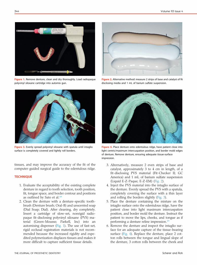
Figure 1. Remove denture, clean and dry thoroughly. Load radiopaquepolyvinyl siloxane cartridge into automix gun.
Figure 2. Alternative method: measure 2 strips of base and catalyst of fitdisclosing media and 1 mL of barium sulfate suspension.
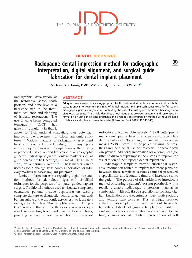
Figure 3. Evenly spread polyvinyl siloxane with spatula until intagliosurface is completely covered and lightly roll borders.
Figure 4. Place denture onto edentulous ridge, have patient close intolight centric/maximum intercuspation position, and border mold edgesof denture. Remove denture, ensuring adequate tissue-surfaceimpression.
344 Volume 113 Issue 4
tissues, and may improve the accuracy of the fit of thecomputer-guided surgical guide to the edentulous ridge.
TECHNIQUE
1. Evaluate the acceptability of the existing completedenture in regard to tooth selection, tooth position,fit, tongue space, and border contour and positionsas outlined by Sato et al.18
2. Clean the denture with a denture-specific tooth-brush (Denture brush; Oral-B) and unscented soap(Dial Soap; Dial). After cleaning, dry completely.Insert a cartridge of slow-set, nonrigid radio-paque fit-disclosing polyvinyl siloxane (PVS) ma-terial (Green-Mousse; Parkell, Inc) into anautomixing dispenser (Fig. 1). The use of fast-set,rigid occlusal registration materials is not recom-mended because the increased rigidity and expe-dited polymerization displaces tissues and makes itmore difficult to capture sufficient tissue details.
THE JOURNAL OF PROSTHETIC DENTISTRY
3. Alternatively, measure 2 even strips of base andcatalyst, approximately 3 to 4 cm in length, of afit-disclosing PVS material (Fit-Checker II; GCAmerica) and 1 mL of barium sulfate suspension(Liquid E-Z-Paque; E-Z-EM) (Fig. 2).
4. Inject the PVS material into the intaglio surface ofthe denture. Evenly spread the PVS with a spatula,completely covering the surface with a thin layerand rolling the borders slightly (Fig. 3).
5. Place the denture containing the mixture on theintaglio surface onto the edentulous ridge, have thepatient close into light maximum intercuspationposition, and border mold the denture. Instruct thepatient to move the lips, cheeks, and tongue as ifperforming a denture reline impression.19
6. Remove the denture and inspect the intaglio sur-face for an adequate capture of the tissue-bearingsurface (Fig. 4). Replace the denture, place 2 cot-ton rolls between the tongue and lingual slope ofthe denture, 3 cotton rolls between the cheek and
Scherer and Roh
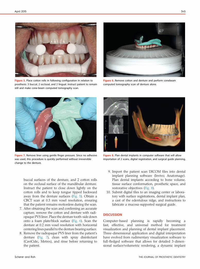
Figure 6. Remove cotton and denture and perform conebeamcomputed tomography scan of denture alone.
Figure 7. Remove liner using gentle finger pressure. Since no adhesivewas used, this procedure is quickly performed without irreversiblechange to the denture.
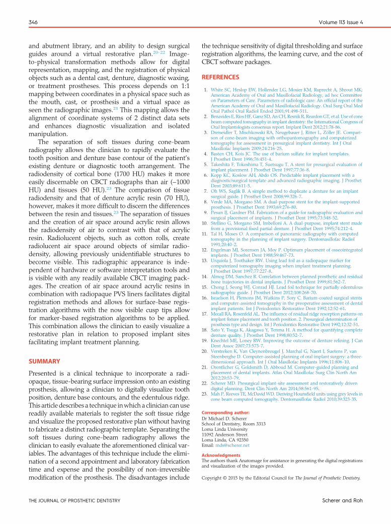
Figure 8. Plan dental implants in computer software that will allowimportation of 2 scans, digital registration, and surgical guide planning.
Figure 5. Place cotton rolls in following configuration in relation toprosthesis: 3 buccal, 2 occlusal, and 2 lingual. Instruct patient to remainstill and make cone-beam computed tomography scan.
April 2015 345
Sc
buccal surfaces of the denture, and 2 cotton rollson the occlusal surface of the mandibular denture.Instruct the patient to close down lightly on thecotton rolls and to keep tongue tipped backwardaway from the denture surfaces (Fig. 5). Obtain aCBCT scan at 0.3 mm voxel resolution, ensuringthat the patient remains motionless during the scan.
7. After obtaining the scan and confirming an accuratecapture, remove the cotton and denture with radi-opaque PVS liner. Place the denture tooth-side downonto a foam plate/block surface (Fig. 6). Scan thedenture at 0.2 mm voxel resolution with horizontalcentering lines parallel to thedenture bearing surface.
8. Remove the radiopaque PVS liner from the patient’sdenture (Fig. 7), clean with spray disinfectant(CaviCide;, Metrex), and rinse before returning tothe patient.
herer and Roh
9. Import the patient scan DICOM files into dentalimplant planning software (Invivo; Anatomage).Plan dental implants according to bone volume,tissue surface conformation, prosthetic space, andrestorative objectives (Fig. 8).
10. Submit digital files to an imaging center or labora-tory with surface registrations, dental implant plan,a cast of the edentulous ridge, and instructions tofabricate a mucosa-supported surgical guide.
DISCUSSION
Computer-based planning is rapidly becoming afast, effective, and universal method for treatmentvisualization and planning of dental implant placement.Three-dimensional application and digital interpretationhave evolved from rudimentary visualization software tofull-fledged software that allows for detailed 3-dimen-sional surface/volumetric rendering, a dynamic implant
THE JOURNAL OF PROSTHETIC DENTISTRY
346 Volume 113 Issue 4
and abutment library, and an ability to design surgicalguides around a virtual restorative plan.20-22 Image-to-physical transformation methods allow for digitalrepresentation, mapping, and the registration of physicalobjects such as a dental cast, denture, diagnostic waxing,or treatment prostheses. This process depends on 1:1mapping between coordinates in a physical space such asthe mouth, cast, or prosthesis and a virtual space asseen the radiographic images.21 This mapping allows thealignment of coordinate systems of 2 distinct data setsand enhances diagnostic visualization and isolatedmanipulation.
The separation of soft tissues during cone-beamradiography allows the clinician to rapidly evaluate thetooth position and denture base contour of the patient’sexisting denture or diagnostic tooth arrangement. Theradiodensity of cortical bone (1700 HU) makes it moreeasily discernable on CBCT radiographs than air (−1000HU) and tissues (50 HU).23 The comparison of tissueradiodensity and that of denture acrylic resin (70 HU),however, makes it more difficult to discern the differencesbetween the resin and tissues.23 The separation of tissuesand the creation of air space around acrylic resin allowsthe radiodensity of air to contrast with that of acrylicresin. Radiolucent objects, such as cotton rolls, createradiolucent air space around objects of similar radio-density, allowing previously unidentifiable structures tobecome visible. This radiographic appearance is inde-pendent of hardware or software interpretation tools andis visible with any readily available CBCT imaging pack-ages. The creation of air space around acrylic resins incombination with radiopaque PVS liners facilitates digitalregistration methods and allows for surface-base regis-tration algorithms with the now visible cusp tips allowfor marker-based registration algorithms to be applied.This combination allows the clinician to easily visualize arestorative plan in relation to proposed implant sitesfacilitating implant treatment planning.
SUMMARY
Presented is a clinical technique to incorporate a radi-opaque, tissue-bearing surface impression onto an existingprosthesis, allowing a clinician to digitally visualize toothposition, denture base contours, and the edentulous ridge.This article describes a technique inwhich a clinician canusereadily available materials to register the soft tissue ridgeand visualize the proposed restorative plan without havingto fabricate a distinct radiographic template. Separating thesoft tissues during cone-beam radiography allows theclinician to easily evaluate the aforementioned clinical var-iables. The advantages of this technique include the elimi-nation of a second appointment and laboratory fabricationtime and expense and the possibility of non-irreversiblemodification of the prosthesis. The disadvantages include
THE JOURNAL OF PROSTHETIC DENTISTRY
the technique sensitivity of digital thresholding and surfaceregistration algorithms, the learning curve, and the cost ofCBCT software packages.
REFERENCES
1. White SC, Heslop EW, Hollender LG, Mosier KM, Ruprecht A, Shrout MK;American Academy of Oral and Maxillofacial Radiology, ad hoc Committeeon Parameters of Care. Parameters of radiologic care: An official report of theAmerican Academy of Oral and Maxillofacial Radiology. Oral Surg Oral MedOral Pathol Oral Radiol Endod 2001;91:498-511.
2. Benavides E, RiosHF,GanzSD, AnCH, ResnikR, ReardonGT, et al. Use of conebeam computed tomography in implant dentistry: the International Congress ofOral Implantologists consensus report. Implant Dent 2012;21:78-86.
3. Dreiseidler T, Mischkowski RA, Neugebauer J, Ritter L, Zöller JE. Compari-son of cone-beam imaging with orthopantomography and computerizedtomography for assessment in presurgical implant dentistry. Int J OralMaxillofac Implants 2009;24:216-25.
4. Basten CH, Kois JC. The use of barium sulfate for implant templates.J Prosthet Dent 1996;76:451-4.
5. Takeshita F, Tokoshima T, Suetsugu T. A stent for presurgical evaluation ofimplant placement. J Prosthet Dent 1997;77:36-8.
6. Kopp KC, Koslow AH, Abdo OS. Predictable implant placement with adiagnostic/surgical template and advanced radiographic imaging. J ProsthetDent 2003;89:611-5.
7. Oh WS, Saglik B. A simple method to duplicate a denture for an implantsurgical guide. J Prosthet Dent 2008;99:326-7.
8. Verde MA, Morgano SM. A dual-purpose stent for the implant-supportedprosthesis. J Prosthet Dent 1993;69:276-80.
9. Pesun IJ, Gardner FM. Fabrication of a guide for radiographic evaluation andsurgical placement of implants. J Prosthet Dent 1995;73:548-52.
10. Stellino G, Morgano SM, Imbelloni A. A dual-purpose, implant stent madefrom a provisional fixed partial denture. J Prosthet Dent 1995;74:212-4.
11. Tal H, Moses O. A comparison of panoramic radiography with computedtomography in the planning of implant surgery. Dentomaxillofac Radiol1991;20:40-2.
12. Engelman MJ, Sorensen JA, Moy P. Optimum placement of osseointegratedimplants. J Prosthet Dent 1988;59:467-73.
13. Urquiola J, Toothaker RW. Using lead foil as a radiopaque marker forcomputerized tomography imaging when implant treatment planning.J Prosthet Dent 1997;77:227-8.
14. Almog DM, Sanchez R. Correlation between planned prosthetic and residualbone trajectories in dental implants. J Prosthet Dent 1999;81:562-7.
15. Chong J, Seong WJ, Conrad HJ. Lead foil technique for partially edentulousradiographic guide. J Prosthet Dent 2012;108:268-70.
16. Israelson H, Plemons JM, Watkins P, Sory C. Barium-coated surgical stentsand computer-assisted tomography in the preoperative assessment of dentalimplant patients. Int J Periodontics Restorative Dent 1992;12:52-61.
17. Mecall RA, Rosenfeld AL. The influence of residual ridge resorption patterns onimplant fixture placement and tooth position. 2. Presurgical determination ofprosthesis type and design. Int J Periodontics Restorative Dent 1992;12:32-51.
18. Sato Y, Tsuga K, Akagawa Y, Tenma H. A method for quantifying completedenture quality. J Prosthet Dent 1998;80:52-7.
19. Knechtel ME, Loney RW. Improving the outcome of denture relining. J CanDent Assoc 2007;73:573-7.
20. Verstreken K, Van Cleynenbreugel J, Marchal G, Naert I, Suetens P, vanSteenberghe D. Computer-assisted planning of oral implant surgery: a three-dimensional approach. Int J Oral Maxillofac Implants 1996;11:806-10.
21. Orentlicher G, Goldsmith D, Abboud M. Computer-guided planning andplacement of dental implants. Atlas Oral Maxillofac Surg Clin North Am2012;20:53-79.
22. Scherer MD. Presurgical implant-site assessment and restoratively drivendigital planning. Dent Clin North Am 2014;58:561-95.
23. Mah P, Reeves TE, McDavidWD. Deriving Hounsfield units using grey levels incone beam computed tomography. Dentomaxillofac Radiol 2010;39:323-35.
Corresponding author:Dr Michael D. SchererSchool of Dentistry, Room 3313Loma Linda University11092 Anderson StreetLoma Linda, CA 92350Email: [email protected]
AcknowledgmentsThe authors thank Anatomage for assistance in generating the digital registrationsand visualization of the images provided.
Copyright © 2015 by the Editorial Council for The Journal of Prosthetic Dentistry.
Scherer and Roh