Embed Size (px)
Citation preview

1
Computed Radiography April 2007Zscherpel, Ewert
Computed Radiography
- INDE 2007, Kalpakkam, India -
Computed Radiography
- INDE 2007, Kalpakkam, India -
Requests and information to:Dr. U. Zscherpel / BAMe-mail [email protected]
Requests and information to:Dr. U. Zscherpel / BAMe-mail [email protected]
Uwe Zscherpel, Uwe EwertBAM Berlin, Division VIII.3
BerlinBAM

2
Computed Radiography April 2007Zscherpel, Ewert
New Technologies and Film ReplacementNew Technologies and Film Replacement
ImagingPlates
Scannerfor Imaging Plates
Hard CopyGrayscalePrinterAgfa
CR: Mobile Orex Scanner
CR:FujiFilm XG1 NDT
Radiographywith
Imaging Plates(CR)

3
Computed Radiography April 2007Zscherpel, Ewert
Erasure
Re-usage
Read-out
Exposure
• high sensitivity• medium resolution• high dynamic range• re-usable
Laser
Lumisys ACR2000
Imaging Plate CycleComputed RadiographyImaging Plate CycleComputed Radiography

4
Computed Radiography April 2007Zscherpel, Ewert
Storage Principle of Luminescence Imaging PlatesStorage Principle of Luminescence Imaging Plates
BaFCl:Eu scintillator BaFBr:Eu storage phosphor

5
Computed Radiography April 2007Zscherpel, Ewert

6
Computed Radiography April 2007Zscherpel, Ewert
Comparison of step wedge exposures
Comparison of step wedge exposures
X-ray tube
BAS 2000
IP
Film
a) Imaging plate system with log.amplifier.The grey level is proportional to the wall thickness.
b) Digitized film.The grey level is proportional tothe light intensity behind the film.
a) Imaging plate system with log.amplifier.The grey level is proportional to the wall thickness.
b) Digitized film.The grey level is proportional tothe light intensity behind the film.
Comparison:a) Imaging plates (IP) andb) Film

7
Computed Radiography April 2007Zscherpel, Ewert
Subject Contrast
Image Quality Parameters
Radiographic Image Quality is the basis for all comparisonsDigital Detector
Detector Contrast Noise Detector Unsharpness Projected Unsharpness
SNR Detector Contrast: Signalfor linear detectors
Detectors can be qualified and classified by its SNR and BSR values!
CNRCNR - Contrast/Noise Ratio SNR - Signal/Noise Ratio
BSR – Basic Spatial Resolution(effektive pixel size)
CNR = SNR(ITot) ⋅ Δw⋅µ/(1 + k)
k = IScatter / I Primary

8
Computed Radiography April 2007Zscherpel, Ewert
Signal/Noise Ratio
Definition of Signal/Noise Ratio andContrast/Noise Ratio
Signal
2*Noise
Contrast
D-D
0
0
Signal proportionalto radiation dose!

9
Computed Radiography April 2007Zscherpel, Ewert
Digital Industrial Radiology
Film Replacement
Standards, Regulations
• Welding
• Casting
All film based standards require:
• Minimum optical Density (e.g. > 2.0)• Maximum film system class (e.g. ≤ ASTM special) • Maximum unsharpness (> 0.1 mm, FFD/FOD)
Comparison of SystemsComparison of Systems
Standards EN 14784 for CR were developed to be comparable with EN 444, EN 584-1, EN 462-5 !

10
Computed Radiography April 2007Zscherpel, Ewert
Film replacement: What is the Optical Density ?
Film
Luxmeter
6000
Luxmeter
60
Light sourceLight intensity measurement
Io
I1
Optical Density = log (Io / I1)
• The opt. density is a measure of light absorption by film
• No digital X-ray detector yields an optical density
• There exist software on the market which provides wrong equivalent values for the optical density of CR or DR systems!
Film reading from light box, D=2:
Sensor

11
Computed Radiography April 2007Zscherpel, Ewert
NDT film as linear radiation detector (D-D0) ∝ K:NDT film as linear radiation detector (D-D0) ∝ K:
steel, 160 kV

12
Computed Radiography April 2007Zscherpel, Ewert
Film system classes havedifferent SNR values atopt. density = 2 fordifferent dose values(EN 584-1, ASTM E 1815)
Film system classes havedifferent SNR values atopt. density = 2 fordifferent dose values(EN 584-1, ASTM E 1815)
AGFA films 2002 -2004In mixed systems
all NDT film systemsof all vendorsalong one line!
SNRfilm ∝√(D-D0)SNRfilm ∝√(D-D0)
SNRMax(class Cx, D<4.5)SNRMax(class Cx, D<4.5)
square root (dose / mGy)

13
Computed Radiography April 2007Zscherpel, Ewert
Film System Classes are the Basis for CR Classificationand all Digital Detectors
Film System Classes are the Basis for CR Classificationand all Digital Detectors
Tab. 1: Overview about the film system classes in different standards and
the corresponding SNR values and G2/σD values.
Minimum gradient-noise ratio at Signal to Noise Ratio
D=2 above D0 D=2 above D0
G2/σD SNRC1 Special 300 130C2 270 117C3 180 78C4 150 65
T3 C5 II T3 120 52
T4 C6 III T4 100 43
W-A W-A 135W-B W-B 110W-C W-C 80
T1
T2
System class
T1
T2
World ISO 11699-1
Europe CEN 584-1
USA ASTM
E1815-01
Japan K7627-97
I
SNR = log(e) ⋅ (G2/σD)for linear detectors only
230! 100!
EN 14784 Part 1: Classification of Systems

14
Computed Radiography April 2007Zscherpel, Ewert
Table 1: IP-scanner system classes in dependence on the minimum SNR
IP System classes System class CEN
System class ISO
System class ASTM
Minimum Signal-noise ratio
IP 1 IP-AS Special 130 IP 2 IP-T 1 117 IP 3 78 IP 4 IP-T2 IP-AS 1 65 IP 5 IP-T3 IP-AS 2 52 IP 6 IP-T4 IP-AS 3 43 NOTE:The SNR-values of table 1 are equivalent to EN 584-1, ISO 11699-1, ASTM E 1815-96 They are calculated by: SNR = log (e) · (Gradient/Granularity) of table 1 of the corresponding standards and up-rounded. The calculation of measured SNR values shall be performed from dose proportional data.
CR System classesCR System classes
New table 1 with 6 classes!
Classification by - SNR and- Spatial resolutione.g.: IP-3/200
Part 1: Classification of Systems

15
Computed Radiography April 2007Zscherpel, Ewert
FUJI XG-1 CR System Classification (BSR = 130 µm)
SNR 0.1mm Pb f&b versus SQRT(Dose/mGy)
y = -0,7114x4 + 11,315x3 - 63,635x2 + 159xR2 = 0,9974
0,00
20,00
40,00
60,00
80,00
100,00
120,00
140,00
160,00
180,00
0,0 0,2 0,4 0,6 0,8 1,0 1,2 1,4 1,6 1,8
01Pb f&b 130µm
Polynomisch (01Pb f&b 130µm)
Wurzel (Dosis)
SNR
CR problem:SNR limited by structure noiseof imaging plates!

16
Computed Radiography April 2007Zscherpel, Ewert
Exp. Time 1x Exp. Time 4.3x Exp. Time 43x
BAM 5 test weld, 8 mm Steel, 120 kV, different exposure time:
magnification CR-System: FujiFilm DynamiX (XG 1)

17
Computed Radiography April 2007Zscherpel, Ewert
• Film systems are characterized by sensitivity(speed) and the SNR at D=2. The spatialresolution is high, rarely used and typicallylimited by geometrical unsharpness of exposureset-up (shortest exposure time!).
• Digital detectors have a higher dynamic range, theSNR depends on exposure. The spatial resolutionis limited (digital file size!).
Basic differencesFilm – Imaging Plate:
Basic differencesFilm – Imaging Plate:
18
Computed Radiography April 2007Zscherpel, Ewert
Status and Situation for CR:
- 2005: Computed Radiology standards were completed and published in USA and Europe!
- The CR procedure is different from the film radiography procedure
- The optical impression of digital radiographic images is not different from film images in its structure (if not digitally processed, except brightness and contrast control)
- RT-trained personal can interpret digital images in analogy to film
- Digital images need a PC for presentation and may be altered by specialized image processing
- A basic training in image processing is essential to avoid miss interpretation
- Quantitative assessment of flaw sizes is improved by digital processing but the results may differ from those ones of film interpretation
- Electronic reference catalogues may support correct image assessment
CR ProcedureCEN EN 14784-2
ASTM E 2033
CR ProcedureCEN EN 14784-2
ASTM E 2033

19
Computed Radiography April 2007Zscherpel, Ewert

20
Computed Radiography April 2007Zscherpel, Ewert
2005

21
Computed Radiography April 2007Zscherpel, Ewert
- The contrast sensitivity improves with the increasing exposure time (better SNR, weaker details becomes visible!)
- The structural noise of the IPs limits the max. achievable SNR
- Step hole, plate hole and wire image quality indicators measure the increase of CNR and improvement of contrast sensitivity
- Unsharp imaging plates achieve a higher max. SNR and need less exposuretime
- The normalized SNRN (with BSR) is independent on the unsharpness, but depends on the efficiency and plate homogeneity
- Only unsharp IPs for radiography with higher energy (about > 250 keV) yield a considerable reduction of exposure time in comparison to film.
Achievable Contrast Sensitivity and Exposure Time

22
Computed Radiography April 2007Zscherpel, Ewert
Wire IQI EN 462-1
Description of Wire -IQI
See also ASTM E747-97→ but different to EN 462
For contrast only !For contrast only !
Duplex wire IQI / EN 462-5 / ASTM E 2002
Lead marks Plastic
Both IQI’s are requiredfor CR!Both IQI’s are requiredfor CR!
For unsharpness only !For unsharpness only !
Step-Hole IQI EN 462-2
Required Image Quality Indicators for CR

23
Computed Radiography April 2007Zscherpel, Ewert
CRSystem Selection
European StandardEN 14784-2

24
Computed Radiography April 2007Zscherpel, Ewert
EN 14784-2

25
Computed Radiography April 2007Zscherpel, Ewert
8 9 10 11 12 13 double wire0.32 0.25 0.20 0.16 0.13 0.10 mm unsharpness
Agfa Prototype (blue)
FujiFilm NDT
Agfa NDT
X-ray tube: Seifert Isovolt 320100 kV, 1 mA, 1 min, small focusSDD = 1000 mm
X-ray tube: Seifert Isovolt 320100 kV, 1 mA, 1 min, small focusSDD = 1000 mm
digitised grey valuesscanning: Agfa DPS, pixel distance: 28.2 µm (900 dpi)
8 9 10 11 12 13
Correct IP-Type

26
Computed Radiography April 2007Zscherpel, Ewert
High Definition CR – Dürr Germany -High Definition CR – Dürr Germany -
Flexible IP (14“x17“) on mobile CR scanner (Dürr)50 k€
Important Advantages:- flexible imaging plates (IP) indirect contact with inner canister wall
- arbitrary formats possible (length notlimited, width max. 14“ (35cm)
- could even be tried with existing set-up (colimator, rotating canister)
- small Laser spot (8 µm) allowssmall BSR for high resolution plates
High resolution mode (BSR=40 µm with suitableImaging plate) available, with thicker IP high Sensitivity achievable (BSR 100 … 200 µm)
Disadvantages:- No automated inspection- Manual handling for IP read-out- IP based on BaFBr have limitedabsorption efficiency
scan direction
For more information see www.duerr-ndt.de

27
Computed Radiography April 2007Zscherpel, Ewert
High Definition CR Systems
HD CR 35 NDT:of Dürr, Germany
HD-IP, light blue
Systems available down to• 12 µm pixel pitch and • 40 µm basic spatial resolution
• “weld quality”

28
Computed Radiography April 2007Zscherpel, Ewert
BAM Certification 2006

29
Computed Radiography April 2007Zscherpel, Ewert
Improvement of CNRUnder Discussion:- Intermediate filters- Pre filters- Max tube voltage
Lead screens may damage the IPs! EN 14784-2

30
Computed Radiography April 2007Zscherpel, Ewert
Improvement of CNRUnder Discussion:- Intermediate filters- Pre filters- Max tube voltage (lower than for film!) Designation: E 2033–xx
Draft
Lead screens may damage the IPs!
TABLE 1 Lead Screen and Filter Thickness
Lead Thickness A KV Range Front Screen Maximum, in. Back Screen Minimum, in. Filter at Tube port > 40kV None. None. <2mm Be Tube Port 40 to 55kV None. None. 0.04 Alum. (1mm) 55 to 90kV None – 0.001 (25µm) None - 0.001 (25µm) 0.04 Alum. (1mm) 90 to 120 kV 0.002 (50µm) 0.002 (50µm) 0.08 Alum. (2mm) 120 to 160kV 0.005 (125µm) 0.005 (125µm) 0.01 Copper (250µm) 160 to 200 kV 0.01 (0.25 mm) 0.01 (0.25 mm) 0.04 Copper (1mm) 200 to 320kV 0.02 (0.5mm) 0.02 (0.5mm) 0.118 Copper (3mm) 320kV-420kV 0.04 (1mm) 0.04 (1mm) 0.236 Copper (6mm) 1MeV to < ? 0.04 (1mm) ?0.04 (1mm) None Se135 0.01 (0.25mm) 0.01 (0.25mm) None Ir192 0.02 (0.5mm) 0.02 (0.5mm) None Co60 0.04 (1mm) 0.04 (1mm) None
≥ ≥

31
Computed Radiography April 2007Zscherpel, Ewert
EN 14784-1, ASTM E 2445
CR Phantom- long term stability tests -
Evaluation of Phantom:
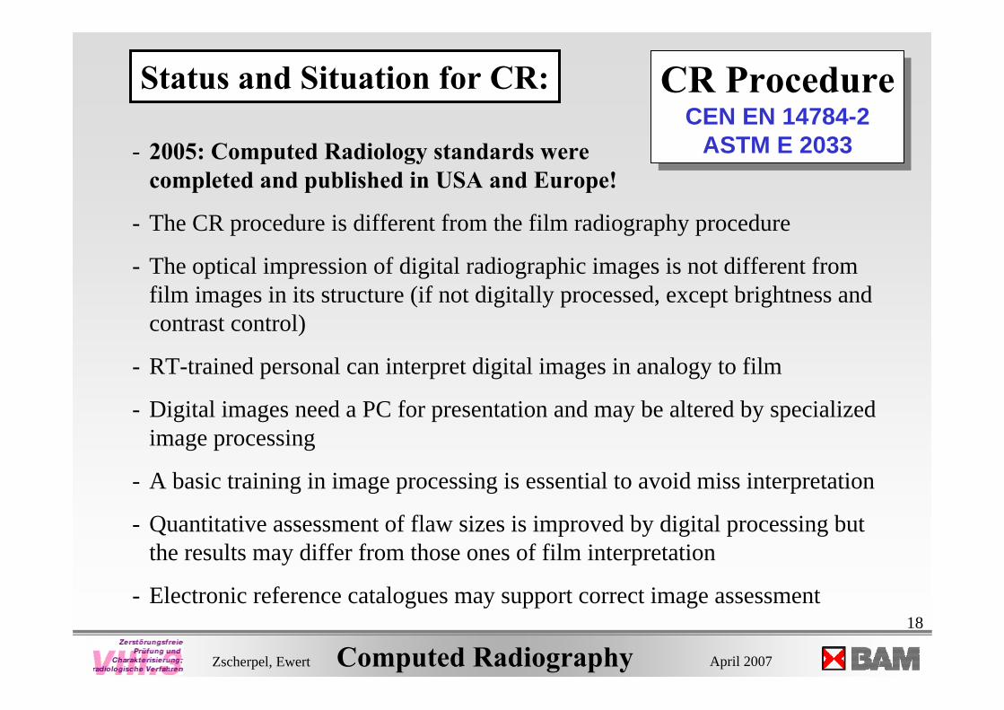
• spatial resolution (by duplex-wire method, optional converging line pairs)• contrast (recognized contrast percentage of the material to examine)• slipping (yes/no)• jitter (yes/no) • MTF (European standard only)• shading (percentage at selected distance)• SNRN (Intensity) near BAM-snail 20x400 window recommended

32
Computed Radiography April 2007Zscherpel, Ewert
EN 14784-1Appendix B:

33
Computed Radiography April 2007Zscherpel, Ewert
Photograph:
35x43 cm²
Protoype
Available from:
- Fluke Biomedical,Part/No. 07-605-2435, 14”x17”www.flukebiomedical.com/rms
- CIT (8”x10”) in U.K.

34
Computed Radiography April 2007Zscherpel, Ewert
CR radiograph90 kV, 2m, 4mAminCR radiograph90 kV, 2m, 4mAmin

35
Computed Radiography April 2007Zscherpel, Ewert
Duplex wire IQIDuplex wire IQI
BAM-snail for test of source position 20% dip
Pair 9 = 260 µm
EN 462-5: unsharpness 0.26 mm
BSR = 0.13 mm

36
Computed Radiography April 2007Zscherpel, Ewert
Converging line pair IQI
3.6 lp/mmUnsharpness = 280 µm
Basic Spatial Resolution = 140 µm
Problems arise for high resolutionsystems; aliasing effects
Problems arise for high resolutionsystems; aliasing effects
BAM-snail for test of source position

37
Computed Radiography April 2007Zscherpel, Ewert
Linearity test - Check rulers- Slipping IP was detected by
a line structure in the image.
Scanner needs repair!

38
Computed Radiography April 2007Zscherpel, Ewert
Profile for MTF - MTF calculation from profile:
MTF20 = 1.6 lp/mmUnsharpness = 0.62 mm (too high!)
MTF
Zero Frequency drop indicates internal scatter
- Jitter Test: no problem

39
Computed Radiography April 2007Zscherpel, Ewert
SNRN (Intensity) near BAM-snail 20x400 window recommended
40
Computed Radiography April 2007Zscherpel, Ewert
Documentation of Long Term Stability Tests

41
Computed Radiography April 2007Zscherpel, Ewert
The practice for CR (EN 14784-2) is based on EN 444 and ISO 5579 for NDT film.
Film can be substituted by IPs
The exposure conditions have to be selected to achieve the required SNR and CNR
2 IQIs are required for CNR and BSR
Tab. 4 in EN 14784-2 regulates the device selection, especially the required basic spatial resolution (BSR)
The max tube voltage should be reduced in comparison to film application
Long term stability can be checked by CR Phantom
Summary:Summary:

42
Computed Radiography April 2007Zscherpel, Ewert
END


![Sizes Payload Compensation path XY up to 20 kg - Comoso · Compensation path XY ... Material CR CR CR CR NBR CR CR CR CR CR CR NBR NBR NBR NBR NBR ... Bending [Nm/rad] 474 552 1025](https://img.pdfslide.us/doc/110x75/5af1b3557f8b9ac57a903b0d/sizes-payload-compensation-path-xy-up-to-20-kg-path-xy-material-cr-cr-cr-cr.jpg)