Embed Size (px)
Citation preview
lable at ScienceDirect
Analytical Biochemistry 529 (2017) 10e16
Contents lists avai
Analytical Biochemistry
journal homepage: www.elsevier .com/locate/yabio
Radio-frequency coils for ultra-high field magnetic resonance€Ozlem Ipek, PhDCIBM-AIT, �Ecole Polytechnique F�ed�erale de Lausanne (EPFL), Lausanne, Switzerland
a r t i c l e i n f o
Article history:Received 3 August 2016Received in revised form24 March 2017Accepted 27 March 2017Available online 29 March 2017
Keywords:Magnetic resonanceRadiofrequency (RF) coilsUltra-high field MRSpecific absorption rate (SAR)Electromagnetic field simulationTransmit field (B1þ)
http://dx.doi.org/10.1016/j.ab.2017.03.0220003-2697/© 2017 Elsevier Inc. All rights reserved.
a b s t r a c t
Radiofrequency (RF) coils are key components of magnetic resonance imaging (MRI) systems. The pri-mary purpose of this review is to provide a basic theory of RF coil designs and their characterization bybench measurements, electromagnetic field simulations and MR measurements. With the continuingincrease of magnetic field strength in MRI instruments, the RF wavelength in the subject under studybecomes comparable to or smaller in size than the anatomical dimensions of the tissue under study,which amplifies the signal inhomogeneity. Also, RF energy increases quadratically with the Larmorfrequency, which leads to increased heat deposition in the subject, especially at ultra-high field. ElegantRF coil designs are explored here to address these challenges.
© 2017 Elsevier Inc. All rights reserved.
Introduction
Radiofrequency (RF) coils on magnetic resonance (MR) scannersare used for transmitting and receiving the RF signal at a singlefrequency. An RF pulse is applied for duration of micro-to milli-seconds in order to tip the magnetization from its equilibriumposition. A high-power RF pulse (typically in the kW range) with aconstant amplitude and phase induces a current in the coilconductor. On the receive side, oscillations of the magnetic fielddue to the resonating spins induce a voltage in a coil conductor. Incontrast to the transmit signal, the receive signal is at much lowerpower. Therefore, before the (millivolt-level) signal is digitizedwithan analog-to-digital (A/D) converter, it is first amplified by low-noise preamplifiers. Moreover, sufficient isolation of the signaltransmission from the signal reception is important to protect theMR system's sensitive receive electronics. A transmit/receive switchand active receive blanking are used to ensure that the trans-mission reception signal leakage is minimized. Therefore, thetransmit/receive switch must have high power capacity (4e16 kWfor 7 T), fast switching (<10 ms), and high isolation between the twochannels (>30 dB) [1].
An RF coil consists essentially of an inductor and a capacitor,known as lumped elements. A capacitor can be connected in par-allel and in series for tuning to the appropriate/desired frequency,and for matching to 50 Ohms (U), which is the termination for allMR electronics, respectively (Fig. 1a) [2]. The coil components mustbe non-magnetic and be able to handle a high RF power input. In
general, as a conductor, copper wire, copper tape or silver platedwires can be utilized with non-magnetic parallel-plate ceramiccapacitors or ceramic trimmer (variable, i.e. 1 to 10 pF range) ca-pacitors, non-magnetic inductors, or varnished copper wires usedas an inductor with non-magnetic connectors and coaxial cables at50 U. As an alternative to rigid copper wires, feasibility studies offlexible RF coils using inkjet- [3] and screen- [4] printed conductorshave been reported. The components should be arranged sym-metrically with respect to ground to ensure a zero voltage relativeto the rest of the coil. Maximum conductor length should be smallerthan wavelength/20 to avoid a standing wave between lumpedelements and source [2]. This can be achieved by distributing thecapacitors around the coil.
The RF coil must be tuned at the nuclei Larmor frequency andmatched to 50 U to transmit the maximum input RF power into theimaging subject (Fig. 2). By varying the inductor (in the nH range)and capacitor (in the pF range) values, the reflection coefficient ofthe RF circuit with respect to the 50 U transmission line can beminimized to �13 dB or better. This ensures that the reflectedpower is minimized to 5% of the input RF power. As the resistance inthe circuit increases, the quality of the resonance will be reduced.The sharpness of the resonance peak is described by the qualityfactor (Q-factor) which is defined as the resonance frequencydivided by the full-width-half-maximum bandwidth. Upon loadingof the RF coil with a subject or sample, the Q-factor should drop. Ifthe ratio of the unloaded to loaded Q-factor is 6, the power loss inthe imaged subject is 5-fold greater than the losses in the coil
List of abbreviations
RF RadiofrequencykW kiloWattA/D Analog-to-DigitalT TesladB DecibelF FaradH HenryQ-factor Quality factorS SiemensFOV Field-of-viewSNR Signal-to-noise ratioBOLD Blood-Oxygen-Level DependentfMRI Functional MRI
SAR Specific absorption rateIEC International Electrotechnical CommisionVOPs Virtual observation pointsHz HertzCEM43 Cumulative Equivalent Minutes at 43 �CEM ElectromagneticCAD Computer-Aided DesignPEC Perfect Electric ConductorFDTD Finite-Difference Time-DomainFEM/FIM Finite Element/Integration MethodB1þ map RF field mapping
SA2RAGESaturation prepared with 2 Rapid Gradient EchoesDREAM Dual Refocusing Echo Acquisition MethodCSF Cerebrospinal fluidVNA Vector network analyzer
€O. Ipek / Analytical Biochemistry 529 (2017) 10e16 11
components. A low Q-factor may indicate high loss or a large fre-quency bandwidth.
To mimic the human brain as an imaging subject, a sphere-shaped homogeneous phantom filled with tissue-simulatingliquid or gel can be utilized. A phantom with the same dielectricproperties as typical brain tissue can be utilized to test the RF coilson the bench and on the MR scanner. For example, the averagedielectric constant of the human brain is 55 and electrical con-ductivity is 0.7 S/m at 300 MHz (7 T). The main ingredient of thephantom is water, which has a dielectric constant of 80 at 300MHz.Salt (NaCl) can be added to increase the electrical conductivity,while table sugar is used to decrease the dielectric constant. Butadded sugar leads to a poor quality MR signal. Therefore,polyethylene-based chemicals are preferred along with agar mix-tures to decrease the dielectric constant [5].
The main categories of RF coils are volume and surface coils(Fig. 3). As volume coils permit imaging of a larger field-of-view(FOV) with a homogeneous excitation, surface coils provide highefficiency and sensitivity in the vicinity of the coil. Surface coils aremainly used as a receive coil array, as they are characterized (inaddition to their high receive sensitivity in the vicinity of the coil)by a low noise pick up as they couple to a limited tissue volume [6].Coupling between the array elements leads to resonance peaksplitting and reduced transmit efficiency as a result of the con-ducting current leaking into the neighboring array element.
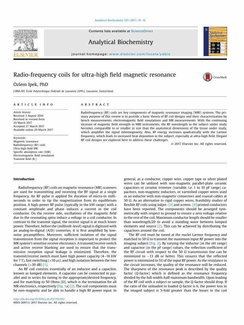
Fig. 1. (a) Picture of a loop RF coil consisting of five parallel-plate ceramic capacitors, coppelength of the copper wire between two adjacent capacitors is less than l/20. (b) Picture of sloop coils used for 7 T MRI/MRS of the occipital lobe of the human brain.
Adjacent surface coil elements [7] can be partially overlapped tocancel the mutual inductance. For the array elements, cable routingmust be fixed to minimize the cable-to-cable coupling as well ascable-to-electronics coupling on the scanner/patient bed.
RF coils can be used as transceivers, independent transmit orreceive coils and as double-tuned coils. The same RF coil trans-mits and receives the RF signal as a transceiver, while separate RFcoil designs are utilized as independent transmit and receive. Forexample, the commercial 7T head coil manufactured by NovaMedical (Wilmington, MA) consists of a single-channelbirdcage transmit coil and 32-channel surface loop receivecoils. The advantage of the multi-channel receive array is to in-crease the local sensitivity in the peripheral part of the brainwhere the transmit field is low (Fig. 6a). This results in enhancedhomogeneity in overall MR signal for conventional gradient echoimaging despite unwanted image contrast changes due tothe variations in the transmit field distribution. This also im-proves the acquisition speed by using parallel imaging methods.Furthermore, multi-nuclei (e.g. 13C, 15N, 31P) MR imaging/spec-troscopy requires single/multiple RF coils tuned to multiplefrequencies. For example, a combination of a linear phosphorousand quadrature proton RF loop coils (Fig. 1b) can be used forthe acquisition of high quality 31P spectra in the occipital lobe ofthe human brain and for proton signal localization andshimming.
r wire, ceramic trimmer capacitors and a coaxial cable. As indicated in the picture, theingle phosphorous (31P) (diameter ¼ 6 cm)/quadrature proton (1H) (diameter ¼ 8 cm)
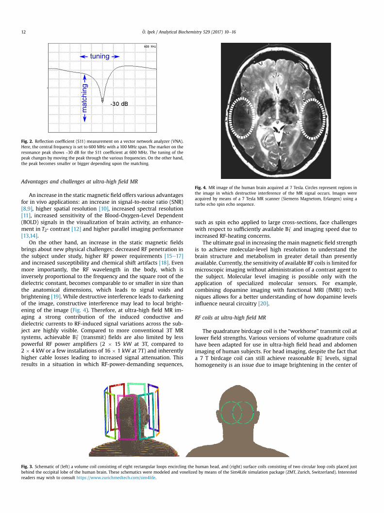
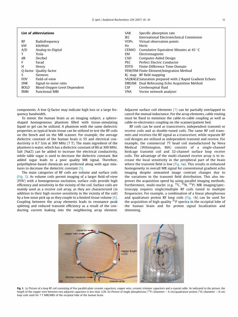
Fig. 4. MR image of the human brain acquired at 7 Tesla. Circles represent regions inthe image in which destructive interference of the MR signal occurs. Images wereacquired by means of a 7 Tesla MR scanner (Siemens Magnetom, Erlangen) using aturbo echo spin echo sequence.
Fig. 2. Reflection coefficient (S11) measurement on a vector network analyzer (VNA).Here, the central frequency is set to 600 MHz with a 100 MHz span. The marker on theresonance peak shows ~30 dB for the S11 coefficient at 600 MHz. The tuning of thepeak changes by moving the peak through the various frequencies. On the other hand,the peak becomes smaller or bigger depending upon the matching.
€O. Ipek / Analytical Biochemistry 529 (2017) 10e1612
Advantages and challenges at ultra-high field MR
An increase in the static magnetic field offers various advantagesfor in vivo applications: an increase in signal-to-noise ratio (SNR)[8,9], higher spatial resolution [10], increased spectral resolution[11], increased sensitivity of the Blood-Oxygen-Level Dependent(BOLD) signals in the visualization of brain activity, an enhance-ment in T2* contrast [12] and higher parallel imaging performance[13,14].
On the other hand, an increase in the static magnetic fieldsbrings about new physical challenges: decreased RF penetration inthe subject under study, higher RF power requirements [15e17]and increased susceptibility and chemical shift artifacts [18]. Evenmore importantly, the RF wavelength in the body, which isinversely proportional to the frequency and the square root of thedielectric constant, becomes comparable to or smaller in size thanthe anatomical dimensions, which leads to signal voids andbrightening [19]. While destructive interference leads to darkeningof the image, constructive interference may lead to local bright-ening of the image (Fig. 4). Therefore, at ultra-high field MR im-aging a strong contribution of the induced conductive anddielectric currents to RF-induced signal variations across the sub-ject are highly visible. Compared to more conventional 3T MRsystems, achievable B1
þ (transmit) fields are also limited by lesspowerful RF power amplifiers (2 � 15 kW at 3T, compared to2 � 4 kW or a few installations of 16 � 1 kW at 7T) and inherentlyhigher cable losses leading to increased signal attenuation. Thisresults in a situation in which RF-power-demanding sequences,
Fig. 3. Schematic of (left) a volume coil consisting of eight rectangular loops encircling thebehind the occipital lobe of the human brain. These schematics were modeled and voxelizereaders may wish to consult https://www.zurichmedtech.com/sim4life.
such as spin echo applied to large cross-sections, face challengeswith respect to sufficiently available B1
þ and imaging speed due toincreased RF-heating concerns.
The ultimate goal in increasing the main magnetic field strengthis to achieve molecular-level high resolution to understand thebrain structure and metabolism in greater detail than presentlyavailable. Currently, the sensitivity of available RF coils is limited formicroscopic imaging without administration of a contrast agent tothe subject. Molecular level imaging is possible only with theapplication of specialized molecular sensors. For example,combining dopamine imaging with functional MRI (fMRI) tech-niques allows for a better understanding of how dopamine levelsinfluence neural circuitry [20].
RF coils at ultra-high field MR
The quadrature birdcage coil is the “workhorse” transmit coil atlower field strengths. Various versions of volume quadrature coilshave been adapted for use in ultra-high field head and abdomenimaging of human subjects. For head imaging, despite the fact thata 7 T birdcage coil can still achieve reasonable B1
þ levels, signalhomogeneity is an issue due to image brightening in the center of
human head, and (right) surface coils consisting of two circular loop coils placed justd by means of the Sim4Life simulation package (ZMT, Zurich, Switzerland). Interested
€O. Ipek / Analytical Biochemistry 529 (2017) 10e16 13
the field of view. Moreover, for abdomen imaging, a 7T volume coilshows limited RF penetration and elevated RF heating in the sub-ject's head, a region outside the RF coil [21]. Recently, Orzada et al.[22] presented a whole-body 32-channel microstrip array, but theywere confronted with the issue of limited RF penetration into thebody even when maximizing RF power input by placing the RFpower amplifiers next to the magnet. This is still preliminary,ongoing hardware development.
Understanding the coil/subject interaction is crucial forobtaining a homogeneous image. The subject, with its various air-,fluid- and tissue-filled cavities, presents a heterogeneous dielectricload, which leads to refraction and reflection of the field compo-nents at the tissue boundaries, resulting in strong field in-terferences. Therefore, the field yielded in the subject by an RF coilstrongly depends on the exact distribution of dielectric propertiesin the subject. Furthermore, wave propagation effects destroy theideal current distribution yielding inefficient transmit distributionon the RF coil around the subject, especially in conjunction withvariable loading situations. One solution to this challenge may bethe use of parallel-transmit methods. Multiple individual RFtransmit coil array elements can be independently driven withvarious RF signal phases and amplitudes [23]. The RF field can behomogenized within the region of interest by shifting and manip-ulating signal void regions within the subject [24,25]. Moreover,user-defined shaped excitation for zoomed imaging is also used infunctional MRI (fMRI). Imaging a specific regionwith a reduced FOVenables faster imaging with reduced sensitivity to motion.
Safety assessment at ultra-high field
A major challenge at ultra-high field imaging is the potential fortissue heating. RF pulses from the coil create time-varying mag-netic-field induced electric fields in the subject according to Max-well's equations. In other words, the electric field induces currentsin the subject, which, in the case of conductive tissues, leads totissue heating. Also, direct electric fields from the RF coil, especiallyaround lumped elements, may also lead to tissue heating. Thespecific absorption rate (SAR) is a measure of the rate at whichenergy is absorbed by the human body when exposed to an elec-tromagnetic field. It is defined as the power absorbed per mass oftissue and has units of watts per kilogram (W/kg). SAR limits aredefined by the International Electrotechnical Commision (IEC)standard [26].
The local SAR level cannot be measured directly; instead, it iscalculated based on electromagnetic field numerical simulations
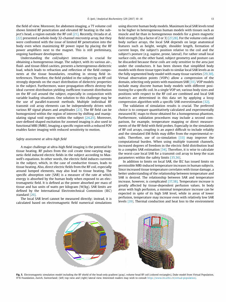
Fig. 5. Electromagnetic simulation model including the RF shield of the head-only gradientIT’IS Foundation, Zurich, Switzerland; (left) top view and (right) lateral view. Interested rea
using discrete human bodymodels. Maximum local SAR levels tendto be higher in heterogeneous human models with tissues such asmuscle and fat than in homogeneous models for a given magneticfield strength (by a factor of 2 or 3) [27,28]. For the volume coils andbody surface arrays, the local SAR depends on large anatomicalfeatures such as height, weight, shoulder length, formation ofcurrent loops, the subject's position relative to the coil and thesubject's posture (e.g. supine, prone, lateral). For rather small localsurface coils, on the other hand, subject geometry and posture canbe discarded because these coils are only sensitive to the area justunder the conductors. It has been shown that simplified bodymodels with three tissue types leads to similar local SAR levels as inthe fully segmented body model with many tissue varieties [29,30].Virtual observation points (VOPs) allow a compression of thedomain, selecting only points withmaximum SAR [31]. VOPmodelsinclude many discrete human body models with different posi-tioning for a specific coil. In a single VOP set, various body sizes andpositions with respect to the RF coil are combined and local SARmatrices are determined in this data set by applying a lossycompression algorithm with a specific SAR overestimation [32].
The validation of simulation results is crucial. The preferredchoice is to compare quantitatively calculated and experimentallymeasured B1
þ maps to those obtained for a homogeneous phantom.Furthermore, validation procedures may include a second com-parison, for example, temperature mapping or direct measure-ments of the RF field with field probes. Especially in the simulationof RF coil arrays, coupling is an aspect difficult to include reliablyand the simulated EM fields may differ from the experimental re-sults. Therefore, use of co-simulation [33] may improve thecomputational burden. When using multiple transmit channels,increased degrees of freedom in the electric field distribution leadto a complex SAR estimation [34]. Therefore, it is wise to calculatethe worst-case local SAR for a transmit coil array to keep the scanparameters within the safety limits [35,36].
In addition to limits on local SAR, the IEC has issued limits onpermissibleMRI-induced temperature increases in human subjects.Since increased tissue temperature correlates with tissue damage, abetter understanding of the relationship between temperature andSAR is desired. The relationship between SAR and temperatureincrease, however, is complicated [37,38]. Temperature increase isgreatly affected by tissue-dependent perfusion values. In bodyareas with high perfusion, a minimal temperature increase can beexpected in spite of its high SAR level, while in areas of lowerperfusion, temperature may increase even with relatively low SARlevels [39]. Thermal conduction and heat loss to the environment
(gray), volume head RF coil (colored rectangles), Duke model from Virtual Population,ders may wish to consult https://www.itis.ethz.ch/virtual-population/.
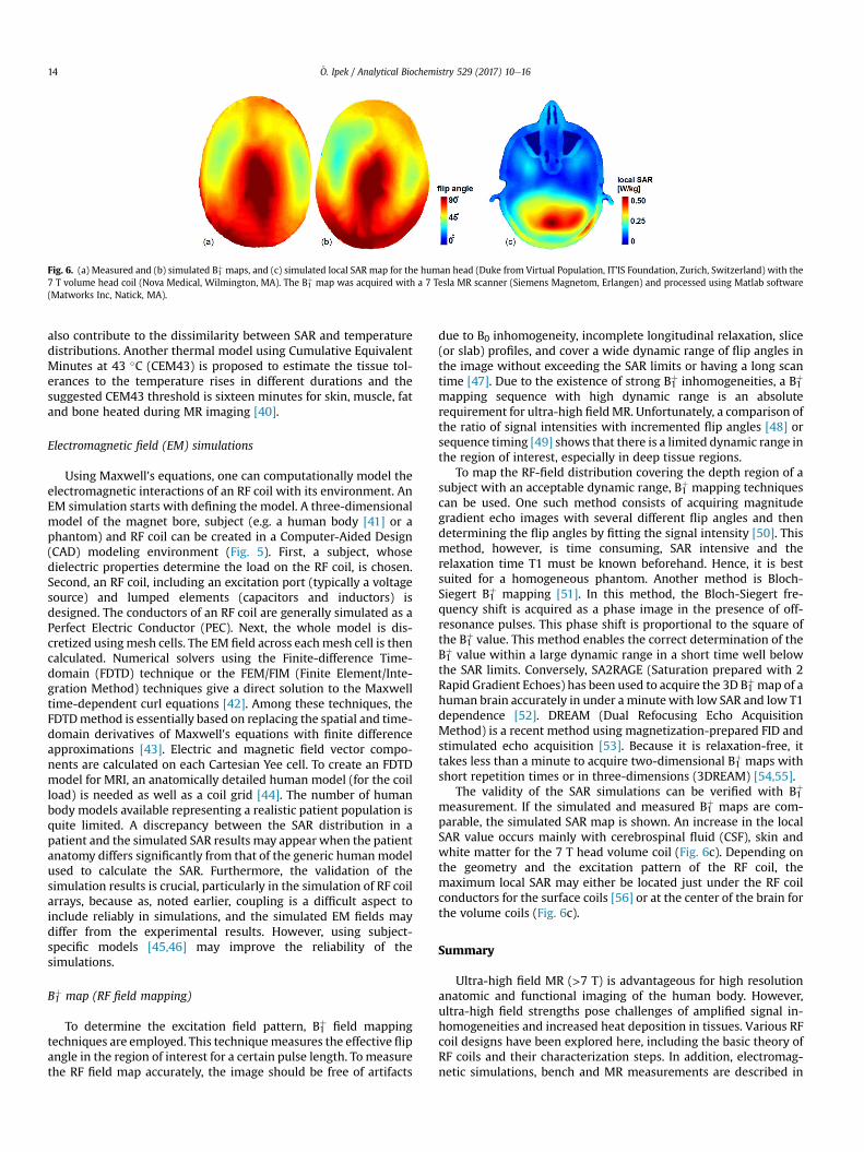
Fig. 6. (a) Measured and (b) simulated B1þ maps, and (c) simulated local SAR map for the human head (Duke from Virtual Population, IT’IS Foundation, Zurich, Switzerland) with the7 T volume head coil (Nova Medical, Wilmington, MA). The B1
þ map was acquired with a 7 Tesla MR scanner (Siemens Magnetom, Erlangen) and processed using Matlab software(Matworks Inc, Natick, MA).
€O. Ipek / Analytical Biochemistry 529 (2017) 10e1614
also contribute to the dissimilarity between SAR and temperaturedistributions. Another thermal model using Cumulative EquivalentMinutes at 43 �C (CEM43) is proposed to estimate the tissue tol-erances to the temperature rises in different durations and thesuggested CEM43 threshold is sixteen minutes for skin, muscle, fatand bone heated during MR imaging [40].
Electromagnetic field (EM) simulations
Using Maxwell's equations, one can computationally model theelectromagnetic interactions of an RF coil with its environment. AnEM simulation starts with defining the model. A three-dimensionalmodel of the magnet bore, subject (e.g. a human body [41] or aphantom) and RF coil can be created in a Computer-Aided Design(CAD) modeling environment (Fig. 5). First, a subject, whosedielectric properties determine the load on the RF coil, is chosen.Second, an RF coil, including an excitation port (typically a voltagesource) and lumped elements (capacitors and inductors) isdesigned. The conductors of an RF coil are generally simulated as aPerfect Electric Conductor (PEC). Next, the whole model is dis-cretized usingmesh cells. The EM field across eachmesh cell is thencalculated. Numerical solvers using the Finite-difference Time-domain (FDTD) technique or the FEM/FIM (Finite Element/Inte-gration Method) techniques give a direct solution to the Maxwelltime-dependent curl equations [42]. Among these techniques, theFDTDmethod is essentially based on replacing the spatial and time-domain derivatives of Maxwell's equations with finite differenceapproximations [43]. Electric and magnetic field vector compo-nents are calculated on each Cartesian Yee cell. To create an FDTDmodel for MRI, an anatomically detailed human model (for the coilload) is needed as well as a coil grid [44]. The number of humanbody models available representing a realistic patient population isquite limited. A discrepancy between the SAR distribution in apatient and the simulated SAR results may appear when the patientanatomy differs significantly from that of the generic humanmodelused to calculate the SAR. Furthermore, the validation of thesimulation results is crucial, particularly in the simulation of RF coilarrays, because as, noted earlier, coupling is a difficult aspect toinclude reliably in simulations, and the simulated EM fields maydiffer from the experimental results. However, using subject-specific models [45,46] may improve the reliability of thesimulations.
B1þ map (RF field mapping)
To determine the excitation field pattern, B1þ field mappingtechniques are employed. This techniquemeasures the effective flipangle in the region of interest for a certain pulse length. To measurethe RF field map accurately, the image should be free of artifacts
due to B0 inhomogeneity, incomplete longitudinal relaxation, slice(or slab) profiles, and cover a wide dynamic range of flip angles inthe image without exceeding the SAR limits or having a long scantime [47]. Due to the existence of strong B1
þ inhomogeneities, a B1þ
mapping sequence with high dynamic range is an absoluterequirement for ultra-high fieldMR. Unfortunately, a comparison ofthe ratio of signal intensities with incremented flip angles [48] orsequence timing [49] shows that there is a limited dynamic range inthe region of interest, especially in deep tissue regions.
To map the RF-field distribution covering the depth region of asubject with an acceptable dynamic range, B1þ mapping techniquescan be used. One such method consists of acquiring magnitudegradient echo images with several different flip angles and thendetermining the flip angles by fitting the signal intensity [50]. Thismethod, however, is time consuming, SAR intensive and therelaxation time T1 must be known beforehand. Hence, it is bestsuited for a homogeneous phantom. Another method is Bloch-Siegert B1
þ mapping [51]. In this method, the Bloch-Siegert fre-quency shift is acquired as a phase image in the presence of off-resonance pulses. This phase shift is proportional to the square ofthe B1
þ value. This method enables the correct determination of theB1þ value within a large dynamic range in a short time well belowthe SAR limits. Conversely, SA2RAGE (Saturation prepared with 2Rapid Gradient Echoes) has been used to acquire the 3D B1
þmap of ahuman brain accurately in under a minutewith low SAR and low T1dependence [52]. DREAM (Dual Refocusing Echo AcquisitionMethod) is a recent method using magnetization-prepared FID andstimulated echo acquisition [53]. Because it is relaxation-free, ittakes less than a minute to acquire two-dimensional B1
þ maps withshort repetition times or in three-dimensions (3DREAM) [54,55].
The validity of the SAR simulations can be verified with B1þ
measurement. If the simulated and measured B1þ maps are com-parable, the simulated SAR map is shown. An increase in the localSAR value occurs mainly with cerebrospinal fluid (CSF), skin andwhite matter for the 7 T head volume coil (Fig. 6c). Depending onthe geometry and the excitation pattern of the RF coil, themaximum local SAR may either be located just under the RF coilconductors for the surface coils [56] or at the center of the brain forthe volume coils (Fig. 6c).
Summary
Ultra-high field MR (>7 T) is advantageous for high resolutionanatomic and functional imaging of the human body. However,ultra-high field strengths pose challenges of amplified signal in-homogeneities and increased heat deposition in tissues. Various RFcoil designs have been explored here, including the basic theory ofRF coils and their characterization steps. In addition, electromag-netic simulations, bench and MR measurements are described in
€O. Ipek / Analytical Biochemistry 529 (2017) 10e16 15
detail. A thorough evaluation of the parameters discussed hereinwill ensure that RF coils can be designed to obtain the best availableimage quality.
Acknowledgements
This study was supported by Centre d’Imagerie BioM�edicale(CIBM) of the UNIL, UNIGE, HUG, CHUV, EPFL and the Leenaards andJeantet Foundations. The author thanks to Dr. Hikari Yoshihara forhis help in editing, Dr. Hongxia Lei for fruitful discussions andJ�er�emie Cl�ement for his assistance in creating Fig. 6.
References
[1] R.D.J.W.E. Doherty Jr., The Pin Diode Circuit Designers Handbook, Microsemi-watertown, 1998.
[2] M.L.J. Mispelter, A. Briquet, NMR Probeheads: for Biophysical and BiomedicalExperiments, Imperial college press, London, 2006.
[3] D. Mager, A. Peter, L.D. Tin, E. Fischer, P.J. Smith, J. Hennig, J.G. Korvink, An MRIreceiver coil produced by inkjet printing directly on to a flexible substrate,IEEE Trans. Med. Imaging 29 (2010) 482e487.
[4] J.R. Corea, A.M. Flynn, B. Lechene, G. Scott, G.D. Reed, P.J. Shin, M. Lustig,A.C. Arias, Screen-printed flexible MRI receive coils, Nat. Commun. 7 (2016).
[5] Q. Duan, J.H. Duyn, N. Gudino, J.A. de Zwart, P. van Gelderen, D.K. Sodickson,R. Brown, Characterization of a dielectric phantom for high-field magneticresonance imaging applications, Med. Phys. 41 (2014) 102303.
[6] J.R.G.J.T. Vaughan, RF Coils for MRI, John Wiley Sons, UK, 2012.[7] P.B. Roemer, W.A. Edelstein, C.E. Hayes, S.P. Souza, O.M. Mueller, The NMR
phased array, Magn. Reson. Med. 16 (1990) 192e225.[8] D.I. Hoult, R.E. Richards, The signal-to-noise ratio of the nuclear magnetic
resonance experiment, J. Magn. Reson. 213 (2011) 329e343.[9] J.T. Vaughan, M. Garwood, C.M. Collins, W. Liu, L. DelaBarre, G. Adriany,
P. Andersen, H. Merkle, R. Goebel, M.B. Smith, K. Ugurbil, 7T vs. 4T: RF power,homogeneity, and signal-to-noise comparison in head images, Magn. Reson.Med. 46 (2001) 24e30.
[10] E. Yacoub, A. Shmuel, J. Pfeuffer, P.-F. Van De Moortele, G. Adriany,P. Andersen, J.T. Vaughan, H. Merkle, K. Ugurbil, X. Hu, Imaging brain functionin humans at 7 Tesla, Magn. Reson. Med. 45 (2001) 588e594.
[11] R. Gruetter, S.A. Weisdorf, V. Rajanayagan, M. Terpstra, H. Merkle, C.L. Truwit,M. Garwood, S.L. Nyberg, K. Ugurbil, Resolution improvements inin Vivo1HNMR spectra with increased magnetic field strength, J. Magn. Reson. 135(1998) 260e264.
[12] J.S. Gati, R.S. Menon, K. Ugurbil, B.K. Rutt, Experimental determination of theBOLD field strength dependence in vessels and tissue, Magn. Reson. Med. 38(1997) 296e302.
[13] K.P. Pruessmann, M. Weiger, M.B. Scheidegger, P. Boesiger, SENSE: sensitivityencoding for fast MRI, Magn. Reson. Med. 42 (1999) 952e962.
[14] D.K. Sodickson, W.J. Manning, Simultaneous acquisition of spatial harmonics(SMASH): fast imaging with radiofrequency coil arrays, Magn. Reson. Med. 38(1997) 591e603.
[15] P.A. Bottomley, W.A. Edelstein, Power deposition in whole-body NMR imag-ing, Med. Phys. 8 (1981) 510e512.
[16] C.N. Chen, V.J. Sank, S.M. Cohen, D.I. Hoult, The field dependence of NMRimaging. I. Laboratory assessment of signal-to-noise ratio and power depo-sition, Magn. Reson. Med. 3 (1986) 722e729.
[17] D.I. Hoult, C.N. Chen, V.J. Sank, The field dependence of NMR imaging. II. Ar-guments concerning an optimal field strength, Magn. Reson. Med. 3 (1986)730e746.
[18] P.-M. Robitaille, L.J. Berliner, Ultra High-field Magnetic Resonance Imaging,Springer, New York, 2006.
[19] C.M. Collins, W. Liu, W. Schreiber, Q.X. Yang, M.B. Smith, Central brighteningdue to constructive interference with, without, and despite dielectric reso-nance, J. Magn. Reson. imaging 21 (2005) 192e196.
[20] T. Lee, L.X. Cai, V.S. Lelyveld, A. Hai, A. Jasanoff, Molecular-level functionalmagnetic resonance imaging of dopaminergic signaling, Science 344 (2014)533e535.
[21] J.T. Vaughan, C.J. Snyder, L.J. DelaBarre, P.J. Bolan, J. Tian, L. Bolinger,G. Adriany, P. Andersen, J. Strupp, K. Ugurbil, Whole-body imaging at 7T:preliminary results, Magn. Reson. Med. 61 (2009) 244e248.
[22] A.K.B.S. Orzada, O. Kraff, N. Oehmigen, M. Gratz, S. Johst, M.N. Volker,S.H.G. Rietsch, M. Floser, T. Fiedler, S. Shooshtary, K. Solbach, H.H. Wuich,M.E. Ladd, A 32-channel integrated body coil for 7 Tesla whole-body imaging,Proc. Int. Soc. Magn. Reson. Med. (2016), 167.
[23] C.M. Collins, W. Liu, B.J. Swift, M.B. Smith, Combination of optimized transmitarrays and some receive array reconstruction methods can yield homoge-neous images at very high frequencies, Magn. Reson. Med. 54 (2005)1327e1332.
[24] G.J. Metzger, C. Snyder, C. Akgun, T. Vaughan, K. Ugurbil, P.F. Van de Moortele,Local B1þ shimming for prostate imaging with transceiver arrays at 7T basedon subject-dependent transmit phase measurements, Magn. Reson. Med. 59
(2008) 396e409.[25] S. Orzada, S. Maderwald, B.A. Poser, A.K. Bitz, H.H. Quick, M.E. Ladd, RF exci-
tation using time interleaved acquisition of modes (TIAMO) to address B1inhomogeneity in high-field MRI, Magn. Reson. Med. 64 (2010) 327e333.
[26] International electrotechnical commission, in: IEC (Ed.), Medical Equipment -IEC 60601-2-33: Particular Requirements for the Safety of Magnetic Reso-nance Equipment, 2010. Geneva.
[27] C.M. Collins, Z. Wang, Calculation of radiofrequency electromagnetic fieldsand their effects in MRI of human subjects, Magn. Reson. Med. 65 (2011)1470e1482.
[28] S. Oh, A.G. Webb, T. Neuberger, B. Park, C.M. Collins, Experimental and nu-merical assessment of MRI-induced temperature change and SAR distribu-tions in phantoms and in vivo, Magn. Reson. Med. 63 (2010) 218e223.
[29] H. Homann, P. B€ornert, H. Eggers, K. Nehrke, O. D€ossel, I. Graesslin, Towardindividualized SAR models and in vivo validation, Magn. Reson. Med. 66(2011) 1767e1776.
[30] €O. Ipek, A.J. Raaijmakers, J.J. Lagendijk, P.R. Luijten, C.A.T. van den Berg,Intersubject local SAR variation for 7T prostate MR imaging with an eight-channel single-side adapted dipole antenna array, Magn. Reson. Med. 71(2014) 1559e1567.
[31] G. Eichfelder, M. Gebhardt, Local specific absorption rate control for paralleltransmission by virtual observation points, Magn. Reson. Med. 66 (2011)1468e1476.
[32] A. Bitz, R. Gumbrecht, S. Orzada, H.-F. Fautz, M. Ladd, Evaluation of virtualobservation points for local sar monitoring of multi-channel transmit RF coilsat 7 tesla, Proc. Int. Soc. Magn. Reson. Med. (2013) 4414.
[33] M. Kozlov, R. Turner, Fast MRI coil analysis based on 3-D electromagnetic andRF circuit co-simulation (San Diego, Calif. : 1997), J. Magn. Reson. 200 (2009)147e152.
[34] F. Seifert, G. Wubbeler, S. Junge, B. Ittermann, H. Rinneberg, Patient safetyconcept for multichannel transmit coils, J. Magn. Reson. imaging 26 (2007)1315e1321.
[35] M. de Greef, O. Ipek, A.J. Raaijmakers, J. Crezee, C.A. van den Berg, Specificabsorption rate intersubject variability in 7T parallel transmit MRI of the head,Magn. Reson. Med. 69 (2013) 1476e1485.
[36] O. Ipek, A.J. Raaijmakers, J.J. Lagendijk, P.R. Luijten, C.A. van den Berg, Inter-subject local SAR variation for 7T prostate MR imaging with an eight-channelsingle-side adapted dipole antenna array, Magn. Reson. Med. 71 (2014)1559e1567.
[37] E.N.M. Murbach, K.P. Pruessmann, N. Kuster, Safe MR scan times based onCEM43 tissue damage thresholds, using electromagnetic and thermal simu-lations with anatomically correct human models and considering local ther-moregulation, Proc. Int. Soc. Magn. Reson. Med. (2012) 313.
[38] Z. Wang, J.C. Lin, W. Mao, W. Liu, M.B. Smith, C.M. Collins, SAR and temper-ature: simulations and comparison to regulatory limits for MRI, J. Magn.Reson. imaging 26 (2007) 437e441.
[39] C.M. Collins, W. Liu, J. Wang, R. Gruetter, J.T. Vaughan, K. Ugurbil, M.B. Smith,Temperature and SAR calculations for a human head within volume andsurface coils at 64 and 300 MHz, J. Magn. Reson. imaging 19 (2004) 650e656.
[40] G.C. van Rhoon, T. Samaras, P.S. Yarmolenko, M.W. Dewhirst, E. Neufeld,N. Kuster, CEM43 degrees C thermal dose thresholds: a potential guide formagnetic resonance radiofrequency exposure levels? Eur. Radiol. 23 (2013)2215e2227.
[41] A. Christ, W. Kainz, E.G. Hahn, K. Honegger, M. Zefferer, E. Neufeld,W. Rascher, R. Janka, W. Bautz, J. Chen, B. Kiefer, P. Schmitt, H.P. Hollenbach,J. Shen, M. Oberle, D. Szczerba, A. Kam, J.W. Guag, N. Kuster, The VirtualFamilyedevelopment of surface-based anatomical models of two adults andtwo children for dosimetric simulations, Phys. Med. Biol. 55 (2010) N23eN38.
[42] Y. Kane, Numerical solution of initial boundary value problems involvingmaxwell's equations in isotropic media, IEEE Trans. Antennas Propag. 14(1966) 302e307.
[43] S.C.H.A. Taflove, Computational Electrodynamics: the Finite Difference TimeDomain Method, Artech House, Boston, 2000.
[44] T.S. Ibrahim, R. Lee, B.A. Baertlein, A. Kangarlu, P.L. Robitaille, Application offinite difference time domain method for the design of birdcage RF head coilsusing multi-port excitations, Magn. Reson. imaging 18 (2000) 733e742.
[45] H. Homann, P. Bornert, H. Eggers, K. Nehrke, O. Dossel, I. Graesslin, Towardindividualized SAR models and in vivo validation, Magn. Reson. Med. 66(2011) 1767e1776.
[46] J. Jin, F. Liu, E. Weber, S. Crozier, Improving SAR estimations in MRI usingsubject-specific models, Phys. Med. Biol. 57 (2012) 8153e8171.
[47] N.G. Dowell, P.S. Tofts, Fast, accurate, and precise mapping of the RF fieldin vivo using the 180 degrees signal null, Magn. Reson. Med. 58 (2007)622e630.
[48] V.L. Yarnykh, Actual flip-angle imaging in the pulsed steady state: a methodfor rapid three-dimensional mapping of the transmitted radiofrequency field,Magn. Reson. Med. 57 (2007) 192e200.
[49] C.H. Cunningham, J.M. Pauly, K.S. Nayak, Saturated double-angle method forrapid B1þ mapping, Magn. Reson. Med. 55 (2006) 1326e1333.
[50] G.J. Barker, A. Simmons, S.R. Arridge, P.S. Tofts, A simple method for investi-gating the effects of non-uniformity of radiofrequency transmission andradiofrequency reception in MRI, Br. J. Radiol. 71 (1998) 59e67.
[51] L.I. Sacolick, F. Wiesinger, I. Hancu, M.W. Vogel, B1 mapping by Bloch-Siegertshift, Magn. Reson. Med. 63 (2010) 1315e1322.
[52] F. Eggenschwiler, T. Kober, A.W. Magill, R. Gruetter, J.P. Marques, SA2RAGE: a
€O. Ipek / Analytical Biochemistry 529 (2017) 10e1616
new sequence for fast B1þ-mapping, Magn. Reson. Med. 67 (2012)1609e1619.
[53] K. Nehrke, P. B€ornert, DREAMda novel approach for robust, ultrafast, multi-slice B1 mapping, Magn. Reson. Med. 68 (2012) 1517e1526.
[54] D. Brenner, D.H.Y. Tse, P.J. Ledden, C. Neumann, T. Stocker, Rapid and accuratepTx B1 mapping using 3DREAMwith dual interferometry, Proc. Int. Soc. Magn.Reson. Med. (2015) 109.
[55] D. Brenner, D.H.Y. Tse, E.D. Pracht, T. Feiweier, S.R.,T. Stocker, 3DREAM - athree-dimensional variant of the DREAM sequence, Proc. Int. Soc. Magn.Reson. Med. (2014) 1455.
[56] O. Ipek, A.J. Raaijmakers, D.W. Klomp, J.J. Lagendijk, P.R. Luijten, C.A. van denBerg, Characterization of transceive surface element designs for 7 teslamagnetic resonance imaging of the prostate: radiative antenna and micro-strip, Phys. Med. Biol. 57 (2012) 343e355.


![Ultra-High Frequency Magnetic Resonance Imagingeprints.nottingham.ac.uk/10740/1/magill_thesis.pdf · Introduction Nuclear Magnetic Resonance (NMR) was first observed by Purcell [1]](https://img.pdfslide.us/doc/110x75/5ed96476f59b0f56f45f6848/ultra-high-frequency-magnetic-resonance-introduction-nuclear-magnetic-resonance.jpg)