Embed Size (px)
Citation preview
THIS MODEL
17.010.0
USES LESS ENERGY
Seasonal Energy Efficiency Ratio - SEER
17.00
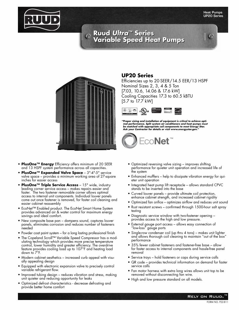
“Proper sizing and installation of equipment is critical to achieve opti-mal performance. Split system air conditioners and heat pumps mustbe matched with appropriate coil components to meet Energy Star. Ask your Contractor for details or visit www.energystar.gov.”
UP20 SeriesEfficiencies up to 20 SEER/14.5 EER/13 HSPFNominal Sizes 2, 3, 4 & 5 Ton [7.03, 10.6, 14.06 & 17.6 kW]Cooling Capacities 17.3 to 60.5 kBTU[5.7 to 17.7 kW]
FORM NO. P22-811
Heat PumpsUP20 Series
Rely on Ruud.™
Ruud Ultra™ Series Variable Speed Heat PumpsRuud Ultra™ Series Variable Speed Heat Pumps
• PlusOne™ Energy Efficiency offers minimum of 20 SEERand 13 HSPF system performance across all capacities.
• PlusOne™ Expanded Valve Space – 3"-4"-5" servicevalve space – provides a minimum working area of 27-squareinches for easier access
• PlusOne™ Triple Service Access – 15" wide, industryleading corner service access – makes repairs easier andfaster. The two fastener removable corner allows optimalaccess to internal unit components. Individual louver panelscome out once fastener is removed, for faster coil cleaning andeasier cabinet reassembly
• EcoNet™ Enabled product. The EcoNet Smart Home Systemprovides advanced air & water control for maximum energysavings and ideal comfort.
• New composite base pan – dampens sound, captures louverpanels, eliminates corrosion and reduces number of fastenersneeded
• Powder coat paint system – for a long lasting professional finish• The Copeland Scroll™ Variable Speed Compressor has a mod-
ulating technology which provides more precise temperaturecontrol, lower humidity and greater efficiency. The overdrivefeature provides cooling load up to 107°F and heating loaddown to 7°F.
• Modern cabinet aesthetics – increased curb appeal with visu-ally appealing design
• Equipped with electronic expansion valve to precisely controlvariable refrigerant flow.
• Improved tubing design – reduces vibration and stress, makingunit quieter and reducing opportunity for leaks
• Optimized defrost characteristics - decrease defrosting andprovide better home comfort
• Optimized reversing valve sizing – improves shifting performance for quieter unit operation and increased life of the system
• Enhanced mufflers – help to dissipate vibration energy for qui-eter unit operation
• Integrated heat pump lift receptacle – allows standard CPVCstands to be inserted into the base
• Curved louver panels – provide ultimate coil protection,enhance cabinet strength, and increased cabinet rigidity
• Optimized fan orifice – optimizes airflow and reduces unit sound• Rust resistant screws – confirmed through 1500-hour salt spray
testing• Diagnostic service window with two-fastener opening –
provides access to the high and low pressure.• External gauge port access – allows easy connection of
“low-loss” gauge ports• Single-row condenser coil (up thru 4 tons) – makes unit lighter
and allows thorough coil cleaning to maintain “out of the box” performance
• 35% fewer cabinet fasteners and fastener-free base – allow for faster access to internal components and hassle-free panelremoval
• Service trays – hold fasteners or caps during service calls• QR code – provides technical information on demand for faster
service calls• Fan motor harness with extra long wires allows unit top to be
removed without disconnecting fan wire.• High and low pressure standard on all models.
Rely on Ruud.™2
Table of ContentsUP20 Series
Standard Feature ......................................................................................................3
Available SKUs ........................................................................................................3
Features & Benefits ..............................................................................................4-8
Model Number Identification ..............................................................................9-10
General Data/Electrical Data ..................................................................................11
Accessories ..........................................................................................................12
Weighted Sound Power ..........................................................................................12
Smart Home Systems ......................................................................................13-14
Unit Dimensions......................................................................................................15
Clearances..............................................................................................................16
Wiring Diagrams ....................................................................................................17
Refrigerant Line Size Information ......................................................................18-19
Performance Data ..................................................................................................20
Guide Specifications ..............................................................................................21
Limited Warranty ....................................................................................................22
TABLE OF CONTENTSTABLE OF CONTENTS
Standard Feature/Available SKUsUP20 Series
Rely on Ruud.™ 3
STANDARD FEATURES
Feature 24 36 48 60
R-410A Refrigerant √ √ √ √Maximum SEER 20 20 20 20Maximum EER 14.5 14 13 13EcoNet Enabled √ √ √ √Copeland Scroll™ Variable Speed Compressor √ √ √ √Compressor Sound Blanket √ √ √ √Variable speed outdoor fan motor √ √ √ √Swept wing fan blade √ √ √ √Field Installed Filter Drier √ √ √ √Front Seating Service Valves √ √ √ √Internal Pressure Relief Valve √ √ √ √Internal Thermal Overload √ √ √ √Low Ambient capability √ √ √ √3-4-5 Expanded Valve Space √ √ √ √Composite Basepan √ √ √ √1" Screw Control Box Access √ √ √ √15" Access to Internal Components √ √ √ √Quick release louver panel design √ √ √ √No fasteners to remove along bottom √ √ √ √Optimized Venturi Airflow √ √ √ √Single row condenser coil √ √ √ 2 RowPowder coated paint √ √ √ √Rust resistant screws √ √ √ √QR code √ √ √ √External gauge ports √ √ √ √Service trays √ √ √ √
√ = Standard
Standard Feature Table
Available SKUsAvailable Models Description
UP2024AJVCA 2 ton EcoNet™ Enabled inverter driven Ruud Ultra™ Series Variable Speed Heat Pump-208/230/1/60
UP2036AJVCA 3 ton EcoNet™ Enabled inverter driven Ruud Ultra™ Series Variable Speed Heat Pump-208/230/1/60
UP2048AJVCA 4 ton EcoNet™ Enabled inverter driven Ruud Ultra™ Series Variable Speed Heat Pump-208/230/1/60
UP2060AJVCA 5 ton EcoNet™ Enabled inverter driven Ruud Ultra™ Series Variable Speed Heat Pump-208/230/1/60
Features & BenefitsUP20 Series
Rely on Ruud.™4
Introduction to UP20 Heat Pump
4
The UP20 is our EcoNet™ Enabled, Inverter Driven Ultra™Series Variable Speed Heat Pump and is part of the Ruud HeatPump product line that extends from 13 to 20 SEER. This highlyfeatured and reliable heat pump is designed for years of reliable,efficient operation when matched with Ruud indoor aluminumevaporator coils and furnaces or air handler units with aluminumevaporators.
The EcoNet Smart Home System is an integrated system for ahome’s Heating, Cooling and Water Heating equipment – allow-ing homeowners to manage the products that consume up to65% of the their home’s energy. EcoNet sets Ruud, and ourdistributor and contractor customers, apart in the industry with aunique, advanced and efficient technology solution.
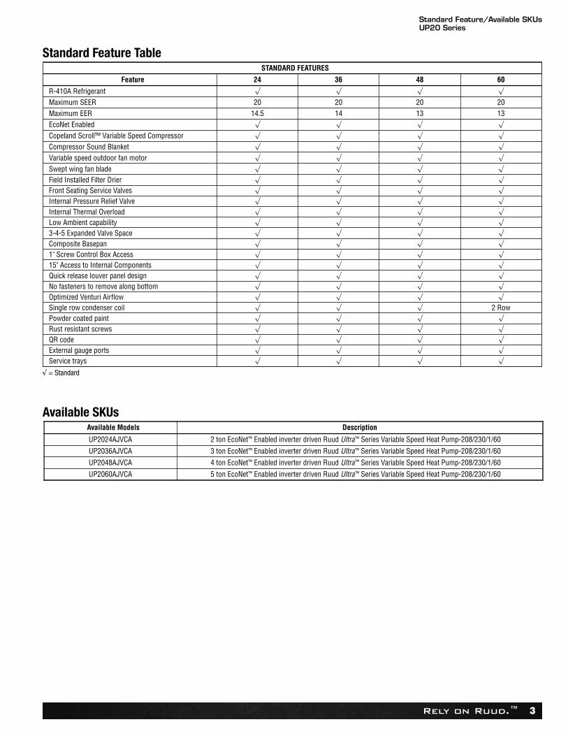
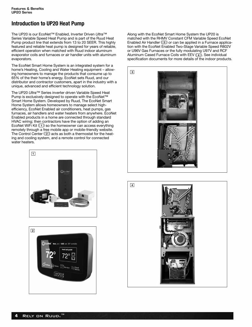
The UP20 Ultra™ Series inverter driven Variable Speed HeatPump is exclusively designed to operate with the EcoNet™Smart Home System. Developed by Ruud, The EcoNet SmartHome System allows homeowners to manage select high-efficiency, EcoNet Enabled air conditioners, heat pumps, gasfurnaces, air handlers and water heaters from anywhere. EcoNetEnabled products in a home are connected through standardHVAC wiring; then contractors have the option of adding anEcoNet WiFi Kit ( ) so the homeowner can access everythingremotely through a free mobile app or mobile-friendly website.The Control Center ( ) acts as both a thermostat for the heat-ing and cooling system, and a remote control for connectedwater heaters.
Along with the EcoNet Smart Home System the UP20 ismatched with the RHMV Constant CFM Variable Speed EcoNetEnabled Air Handler ( ) or can be applied in a Furnace applica-tion with the EcoNet Enabled Two-Stage Variable Speed R802Vor U96V Gas Furnaces or the fully modulating U97V and RCFAluminum Cased Furnace Coils with EEV ( ). See individualspecification documents for more details of the indoor products.
3
4
1
2
1
2
3
Features & BenefitsUP20 Series
Rely on Ruud.™ 5
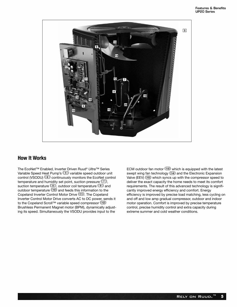
The EcoNet™ Enabled, Inverter Driven Ruud® Ultra™ SeriesVariable Speed Heat Pump’s ( ) variable speed outdoor unitcontrol (VSODU) ( ) continuously monitors the EcoNet controltemperature and humidity set point, suction pressure ( ), suction temperature ( ), outdoor coil temperature ( ) andoutdoor temperature ( ) and feeds this information to theCopeland Inverter Control Motor Drive ( ). The CopelandInverter Control Motor Drive converts AC to DC power, sends itto the Copeland Scroll™ variable speed compressor ( )Brushless Permanent Magnet motor (BPM), dynamically adjust-ing its speed. Simultaneously the VSODU provides input to the
ECM outdoor fan motor ( ) which is equipped with the latestswept wing fan technology ( ) and the Electronic ExpansionValve (EEV) ( ) which syncs up with the compressor speed todeliver the exact capacity the home needs to meet its comfortrequirements. The result of this advanced technology is signifi-cantly improved energy efficiency and comfort. Energyefficiency is improved by precise load matching, less cycling onand off and low amp gradual compressor, outdoor and indoormotor operation. Comfort is improved by precise temperaturecontrol, precise humidity control and extra capacity duringextreme summer and cold weather conditions.
5
6
7
8 9
10
11
12
13
14
15
How It Works
13
9
17
11
16
10
6
18
15
20
8
12
19
7
14
5
Features & BenefitsUP20 Series
Rely on Ruud.™6
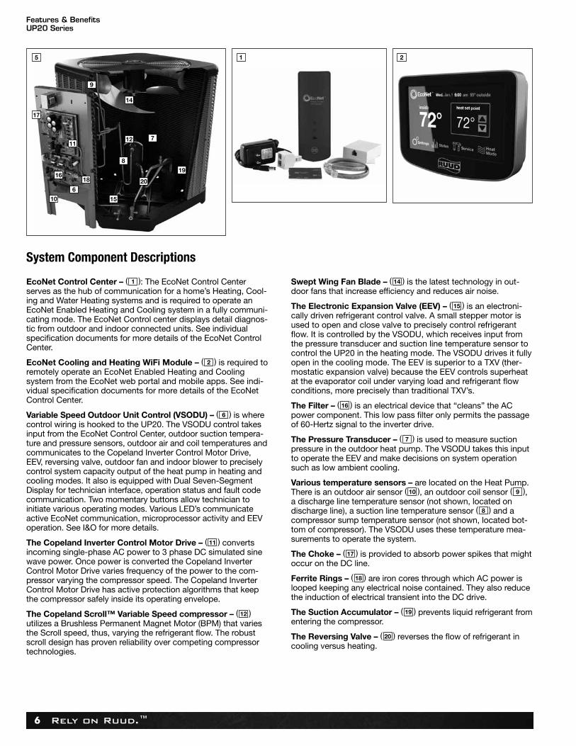
EcoNet Control Center – ( ): The EcoNet Control Centerserves as the hub of communication for a home’s Heating, Cool-ing and Water Heating systems and is required to operate anEcoNet Enabled Heating and Cooling system in a fully communi-cating mode. The EcoNet Control center displays detail diagnos-tic from outdoor and indoor connected units. See individualspecification documents for more details of the EcoNet ControlCenter.
EcoNet Cooling and Heating WiFi Module – ( ) is required toremotely operate an EcoNet Enabled Heating and Cooling system from the EcoNet web portal and mobile apps. See indi-vidual specification documents for more details of the EcoNetControl Center.
Variable Speed Outdoor Unit Control (VSODU) – ( ) is wherecontrol wiring is hooked to the UP20. The VSODU control takesinput from the EcoNet Control Center, outdoor suction tempera-ture and pressure sensors, outdoor air and coil temperatures andcommunicates to the Copeland Inverter Control Motor Drive,EEV, reversing valve, outdoor fan and indoor blower to preciselycontrol system capacity output of the heat pump in heating andcooling modes. It also is equipped with Dual Seven-SegmentDisplay for technician interface, operation status and fault codecommunication. Two momentary buttons allow technician toinitiate various operating modes. Various LED’s communicateactive EcoNet communication, microprocessor activity and EEVoperation. See I&O for more details.
The Copeland Inverter Control Motor Drive – ( ) convertsincoming single-phase AC power to 3 phase DC simulated sinewave power. Once power is converted the Copeland InverterControl Motor Drive varies frequency of the power to the com-pressor varying the compressor speed. The Copeland InverterControl Motor Drive has active protection algorithms that keepthe compressor safely inside its operating envelope.
The Copeland Scroll™ Variable Speed compressor – ( )utilizes a Brushless Permanent Magnet Motor (BPM) that variesthe Scroll speed, thus, varying the refrigerant flow. The robustscroll design has proven reliability over competing compressortechnologies.
Swept Wing Fan Blade – ( ) is the latest technology in out-door fans that increase efficiency and reduces air noise.
The Electronic Expansion Valve (EEV) – ( ) is an electroni-cally driven refrigerant control valve. A small stepper motor isused to open and close valve to precisely control refrigerantflow. It is controlled by the VSODU, which receives input fromthe pressure transducer and suction line temperature sensor tocontrol the UP20 in the heating mode. The VSODU drives it fullyopen in the cooling mode. The EEV is superior to a TXV (ther-mostatic expansion valve) because the EEV controls superheatat the evaporator coil under varying load and refrigerant flowconditions, more precisely than traditional TXV’s.
The Filter – ( ) is an electrical device that “cleans” the ACpower component. This low pass filter only permits the passageof 60-Hertz signal to the inverter drive.
The Pressure Transducer – ( ) is used to measure suctionpressure in the outdoor heat pump. The VSODU takes this inputto operate the EEV and make decisions on system operationsuch as low ambient cooling.
Various temperature sensors – are located on the Heat Pump.There is an outdoor air sensor ( ), an outdoor coil sensor ( ),a discharge line temperature sensor (not shown, located ondischarge line), a suction line temperature sensor ( ) and acompressor sump temperature sensor (not shown, located bot-tom of compressor). The VSODU uses these temperature mea-surements to operate the system.
The Choke – ( ) is provided to absorb power spikes that mightoccur on the DC line.
Ferrite Rings – ( ) are iron cores through which AC power islooped keeping any electrical noise contained. They also reducethe induction of electrical transient into the DC drive.
The Suction Accumulator – ( ) prevents liquid refrigerant fromentering the compressor.
The Reversing Valve – ( ) reverses the flow of refrigerant incooling versus heating.
1
2
6
11
12
14
15
16
7
910
8
17
18
19
20
System Component Descriptions
9
17
11
16
10
6
18
15
20
8
12
19
7
14
5 1 2
Features & BenefitsUP20 Series
Rely on Ruud.™ 7
In addition all UP20 Ultra Series Inverter Driven Variable SpeedHeat Pumps have the following features:
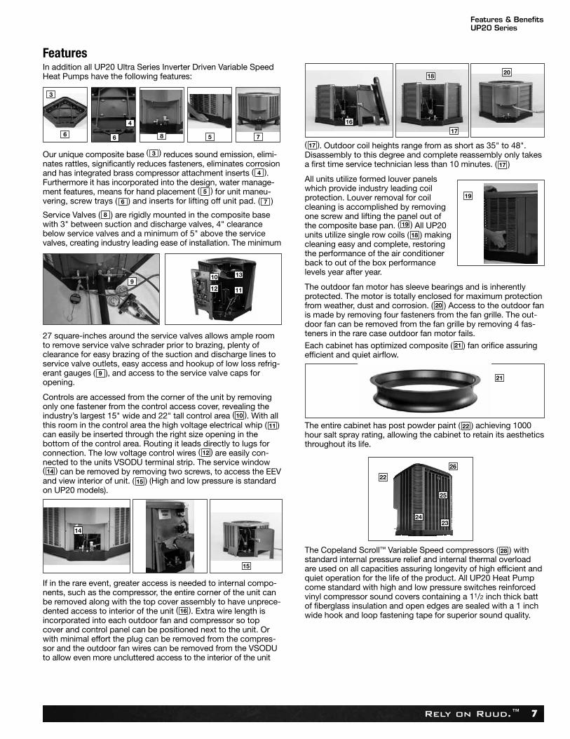
Our unique composite base ( ) reduces sound emission, elimi-nates rattles, significantly reduces fasteners, eliminates corrosionand has integrated brass compressor attachment inserts ( ).Furthermore it has incorporated into the design, water manage -ment features, means for hand placement ( ) for unit maneu -vering, screw trays ( ) and inserts for lifting off unit pad. ( )
Service Valves ( ) are rigidly mounted in the composite basewith 3" between suction and discharge valves, 4" clearancebelow service valves and a minimum of 5" above the servicevalves, creating industry leading ease of installation. The minimum
27 square-inches around the service valves allows ample roomto remove service valve schrader prior to brazing, plenty ofclearance for easy brazing of the suction and discharge lines toservice valve outlets, easy access and hookup of low loss refrig-erant gauges ( ), and access to the service valve caps foropening.
Controls are accessed from the corner of the unit by removingonly one fastener from the control access cover, revealing theindustry’s largest 15" wide and 22" tall control area ( ). With allthis room in the control area the high voltage electrical whip ( )can easily be inserted through the right size opening in the bottom of the control area. Routing it leads directly to lugs forconnection. The low voltage control wires ( ) are easily con-nected to the units VSODU terminal strip. The service window( ) can be removed by removing two screws, to access the EEVand view interior of unit. ( ) (High and low pressure is standardon UP20 models).
If in the rare event, greater access is needed to internal compo-nents, such as the compressor, the entire corner of the unit canbe removed along with the top cover assembly to have unprece-dented access to interior of the unit ( ). Extra wire length isincorporated into each outdoor fan and compressor so topcover and control panel can be positioned next to the unit. Orwith minimal effort the plug can be removed from the compres-sor and the outdoor fan wires can be removed from the VSODUto allow even more uncluttered access to the interior of the unit
( ). Outdoor coil heights range from as short as 35" to 48".Disassembly to this degree and complete reassembly only takesa first time service technician less than 10 minutes. ( )
All units utilize formed louver panelswhich provide industry leading coilprotection. Louver removal for coilcleaning is accomplished by removingone screw and lifting the panel out of the composite base pan. ( ) All UP20units utilize single row coils ( ) makingcleaning easy and complete, restoringthe performance of the air conditionerback to out of the box performancelevels year after year.
The outdoor fan motor has sleeve bearings and is inherentlyprotected. The motor is totally enclosed for maximum protectionfrom weather, dust and corrosion. ( ) Access to the outdoor fanis made by removing four fasteners from the fan grille. The out-door fan can be removed from the fan grille by removing 4 fas-teners in the rare case outdoor fan motor fails. Each cabinet has optimized composite ( ) fan orifice assuringefficient and quiet airflow.
The entire cabinet has post powder paint ( ) achieving 1000hour salt spray rating, allowing the cabinet to retain its aestheticsthroughout its life.
The Copeland Scroll™ Variable Speed compressors ( ) with standard internal pressure relief and internal thermal overloadare used on all capacities assuring longevity of high efficient andquiet operation for the life of the product. All UP20 Heat Pumpcome standard with high and low pressure switches reinforcedvinyl compressor sound covers containing a 11/2 inch thick battof fiber glass insulation and open edges are sealed with a 1 inchwide hook and loop fastening tape for superior sound quality.
4
5
76
8
9
10
11
12
14
15
16
317
17
19
18
20
21
22
28
19
22
26
25
2423
21
Features
3
6 6 5 7
4
8
10 13
11129
15
14
18
16
20
17
Features & BenefitsUP20 Series
Rely on Ruud.™8
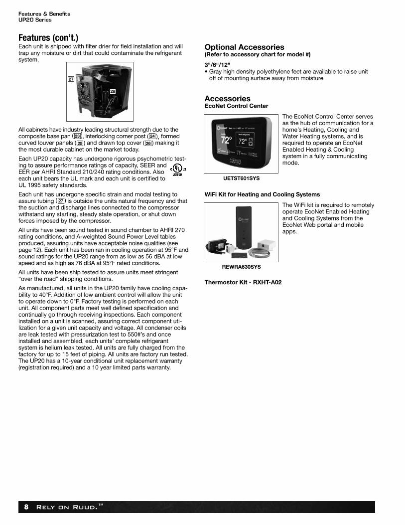
Each unit is shipped with filter drier for field installation and willtrap any moisture or dirt that could contaminate the refrigerantsystem.
All cabinets have industry leading structural strength due to thecomposite base pan ( ), interlocking corner post ( ), formedcurved louver panels ( ) and drawn top cover ( ) making itthe most durable cabinet on the market today.
Each UP20 capacity has undergone rigorous psychometric test-ing to assure performance ratings of capacity, SEER andEER per AHRI Standard 210/240 rating conditions. Alsoeach unit bears the UL mark and each unit is certified toUL 1995 safety standards.
Each unit has undergone specific strain and modal testing toassure tubing ( ) is outside the units natural frequency and thatthe suction and discharge lines connected to the compressorwithstand any starting, steady state operation, or shut downforces imposed by the compressor.
All units have been sound tested in sound chamber to AHRI 270rating conditions, and A-weighted Sound Power Level tablesproduced, assuring units have acceptable noise qualities (seepage 12). Each unit has been ran in cooling operation at 95°F andsound ratings for the UP20 range from as low as 56 dBA at lowspeed and as high as 76 dBA at 95°F rated conditions.
All units have been ship tested to assure units meet stringent“over the road” shipping conditions.
As manufactured, all units in the UP20 family have cooling capa-bility to 40°F. Addition of low ambient control will allow the unitto operate down to 0°F. Factory testing is performed on eachunit. All component parts meet well defined specification andcontinually go through receiving inspections. Each componentinstalled on a unit is scanned, assuring correct component uti-lization for a given unit capacity and voltage. All condenser coilsare leak tested with pressurization test to 550#’s and onceinstalled and assembled, each units’ complete refrigerant system is helium leak tested. All units are fully charged from thefactory for up to 15 feet of piping. All units are factory run tested.The UP20 has a 10-year conditional unit replacement warranty(registration required) and a 10 year limited parts warranty.
Optional Accessories(Refer to accessory chart for model #)
3"/6"/12"• Gray high density polyethylene feet are available to raise unit
off of mounting surface away from moisture
AccessoriesEcoNet Control Center
The EcoNet Control Center servesas the hub of communication for ahome’s Heating, Cooling andWater Heating systems, and isrequired to operate an EcoNetEnabled Heating & Cooling system in a fully communicatingmode.
WiFi Kit for Heating and Cooling Systems
The WiFi kit is required to remotelyoperate EcoNet Enabled Heatingand Cooling Systems from theEcoNet Web portal and mobileapps.
Thermostor Kit - RXHT-A02
2423
2625
27
Features (con’t.)
27
UETST601SYS
REWRA630SYS
28
Model Number IdentificationUP20 Series
Rely on Ruud.™ 9
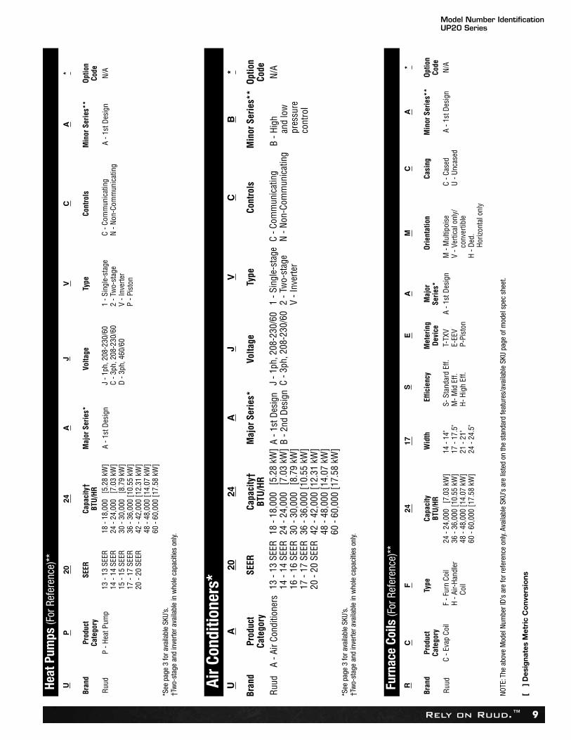
UA
2024
AJ
VC
B*
Bran
dPr
oduc
tCa
tego
rySE
ERCa
paci
ty†
BTU/
HRM
ajor
Ser
ies*
Volta
geTy
peCo
ntro
lsM
inor
Ser
ies*
*Op
tion
Code
Ruud
A
- Air
Cond
ition
ers
13 -
13 S
EER
14 -
14 S
EER
16 -
16 S
EER
17 -
17 S
EER
20 -
20 S
EER
18 -
18,0
00
[5.2
8 kW
]24
- 24
,000
[7
.03
kW]
30 -
30,0
00
[8.7
9 kW
]36
- 36
,000
[10.
55 k
W]
42 -
42,0
00 [1
2.31
kW
]48
- 48
,000
[14.
07 k
W]
60 -
60,0
00 [1
7.58
kW
]
A - 1
st D
esig
nB
- 2nd
Des
ign
J - 1
ph, 2
08-2
30/6
0C
- 3ph
, 208
-230
/60
1 - S
ingl
e-st
age
2 - T
wo-
stag
eV
- Inv
erte
r
C - C
omm
unic
atin
gN
- Non
-Com
mun
icat
ing
B - H
igh
and
low
pr
essu
reco
ntro
l
N/A
UP
2024
AJ
VC
A*
Bran
dPr
oduc
tCa
tego
rySE
ERCa
paci
ty†
BTU/
HRM
ajor
Ser
ies*
Volta
geTy
peCo
ntro
lsM
inor
Ser
ies*
*Op
tion
Code
Ruud
P
- Hea
t Pum
p 13
- 13
SEE
R14
- 14
SEE
R15
- 15
SEE
R17
- 17
SEE
R20
- 20
SEE
R
18 -
18,0
00
[5.2
8 kW
]24
- 24
,000
[7
.03
kW]
30 -
30,0
00
[8.7
9 kW
]36
- 36
,000
[10.
55 k
W]
42 -
42,0
00 [1
2.31
kW
]48
- 48
,000
[14.
07 k
W]
60 -
60,0
00 [1
7.58
kW
]
A - 1
st D
esig
nJ
- 1ph
, 208
-230
/60
C - 3
ph, 2
08-2
30/6
0D
- 3ph
, 460
/60
1 - S
ingl
e-st
age
2 - T
wo-
stag
eV
- Inv
erte
rP
- Pis
ton
C - C
omm
unic
atin
gN
- Non
-Com
mun
icat
ing
A - 1
st D
esig
nN/
A
RC
F24
17S
EA
MC
A*
Bran
dPr
oduc
tCa
tego
ryTy
peCa
paci
tyBT
U/HR
Wid
thEf
ficie
ncy
Met
erin
gDe
vice
Maj
orSe
ries*
Orie
ntat
ion
Casi
ngM
inor
Ser
ies*
*Op
tion
Code
Ruud
C
- Eva
p Co
ilF
- Fur
n Co
ilH
- Air-
Hand
ler
Coil
24 -
24,0
00
[7.0
3 kW
]36
- 36
,000
[10.
55 k
W]
48 -
48,0
00 [1
4.07
kW
]60
- 60
,000
[17.
58 k
W]
14 -
14"
17 -
17.5
"21
- 21
"24
- 24
.5"
S- S
tand
ard
Eff.
M- M
id E
ff.H-
Hig
h Ef
f.
T-TX
VE-
EEV
P-Pi
ston
A - 1
st D
esig
nM
- M
ultip
oise
V - V
ertic
al o
nly/
conv
ertib
leH
- Ded
.Ho
rizon
tal o
nly
C - C
ased
U - U
ncas
edA
- 1st
Des
ign
N/A
Heat
Pum
ps (F
or R
efer
ence
)**
Furn
ace
Coils
(For
Ref
eren
ce)*
*
Air C
ondi
tione
rs*
*See
pag
e 3
for a
vaila
ble
SKU’
s.†T
wo-
stag
e an
d in
verte
r ava
ilabl
e in
who
le c
apac
ities
onl
y.
NOTE
: The
abo
ve M
odel
Num
ber I
D’s
are
for r
efer
ence
onl
y. Av
aila
ble
SKU’
s ar
e lis
ted
on th
e st
anda
rd fe
atur
es/a
vaila
ble
SKU
page
of m
odel
spe
c sh
eet.
[ ]
Des
igna
tes
Met
ric
Co
nver
sio
ns
*See
pag
e 3
for a
vaila
ble
SKU’
s.†T
wo-
stag
e an
d in
verte
r ava
ilabl
e in
who
le c
apac
ities
onl
y.
Model Number IdentificationUP20 Series
Rely on Ruud.™10
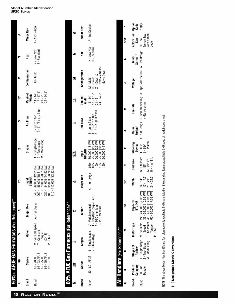
U96
VA
702
317
MS
A
Bran
dSe
ries
Mot
orM
ajor
Rev
Inpu
tBT
U/HR
Stag
esAi
r Flo
wCa
bine
tW
idth
Conf
igur
atio
nNo
xM
inor
Rev
Ruud
90
- 90
AFU
E92
- 92
AFU
E95
- 95
AFU
E96
- 96
AFU
E97
- 97
AFU
E
V - V
aria
ble
spee
dT
- Con
stan
tTo
rque
(X-1
3)P
- PSC
A - 1
st D
esig
n04
0 -
42,0
00 [1
2.31
kW
]06
0 -
56,0
00 [1
6.41
kW
]07
0 -
70,0
00 [2
0.51
kW
]08
5 -
84,0
00 [2
4.62
kW
]10
0 -
98,0
00 [2
8.72
kW
]11
5 - 1
12,0
00 [3
2.82
kW
]
1-S
ingl
e-st
age
2-T
wo-
stag
eM
- M
odul
atin
g
3 - u
p to
3 to
n5
- 3 1
/2 u
p to
5 to
n14
- 14
"17
- 17
.5"
21 -
21"
24 -
24.5
"
M -
Mul
tiX
- Low
Nox
S - S
tand
ard
A - 1
st D
esig
n
U80
2V
A07
53
17M
SA
Bran
dSe
ries
Stag
esM
otor
Maj
or R
evIn
put
BTU/
HRAi
r Flo
wCa
bine
tW
idth
Conf
igur
atio
nNo
xM
inor
Rev
Ruud
80
- 80
+ AF
UE1
- Sin
gle-
stag
e2
- Tw
o-st
age
V - V
aria
ble
spee
dT
- Con
stan
t Tor
que
(X-1
3)P
- PSC
pre
miu
mS
- PSC
sta
ndar
d
A - 1
st D
esig
n05
0 -
50,0
00 [1
5 kW
]07
5 -
75,0
00 [2
2 kW
]10
0 - 1
00,0
00 [2
9 kW
]12
5 - 1
25,0
00 [3
7 kW
]15
0 - 1
50,0
00 [4
4 kW
]
3 - u
p to
3 to
n4
- 2 1
/2 to
4 to
n5
- 3 1
/2 u
p to
5 to
n
14 -
14"
17 -
17.5
"21
- 21
"24
- 24
.5"
M- M
ulti
D- D
own
Z- D
own
&ze
ro c
lear
ance
dow
n flo
w
X - L
ow N
oxS
- Sta
ndar
dA
- 1st
Des
ign
RH
MV
3617
SE
AC
JA
000
*
Bran
dPr
oduc
tCa
tego
rySt
ages
of
Airfl
owM
otor
Typ
eCa
paci
tyBT
U/HR
Wid
thCo
il Si
zeM
eter
ing
Devi
ceM
ajor
Serie
s*Co
ntro
lsVo
ltage
Min
orSe
ries*
*Fa
ctor
y He
atCa
pOp
tion
Code
Ruud
H
- Air
Hand
ler
1 - S
ingl
e-St
age
2 - T
wo-
Stag
eM
- M
odul
atin
g
V - V
aria
ble
Spee
dT
- Con
stan
tTo
rque
P - P
SC
24 -
24,0
00
[7.0
3 kW
]36
- 36
,000
[10.
55 k
W]
48 -
48,0
00 [1
4.07
kW
]60
- 60
,000
[17.
58 k
W]
14 -
14"
17 -
17.5
"21
- 21
"24
- 24
.5"
S - S
tand
ard
Eff.
M -
Mid
Eff.
H - H
igh
Eff.
T - T
EVE
- EEV
P - P
isto
n
A - 1
st D
esig
nC
-Com
mun
icat
ing
N -N
on-c
omm
J- 1
ph, 2
08-2
40/6
0A
- 1st
Des
ign
00 -
nofa
ctor
y he
atw
ith o
ptio
nco
de
*TBD
90%
+ A
FUE
Gas
Furn
aces
(For
Ref
eren
ce)*
*
80%
AFU
E Ga
s Fu
rnac
es (F
or R
efer
ence
)**
Air H
andl
ers
(For
Ref
eren
ce)*
*
NOTE
: The
abo
ve M
odel
Num
ber I
D’s
are
for r
efer
ence
onl
y. Av
aila
ble
SKU’
s ar
e lis
ted
on th
e st
anda
rd fe
atur
es/a
vaila
ble
SKU
page
of m
odel
spe
c sh
eet.
[ ]
Des
igna
tes
Met
ric
Co
nver
sio
ns
General Data/Electrical DataUP20 Series
Rely on Ruud.™ 11
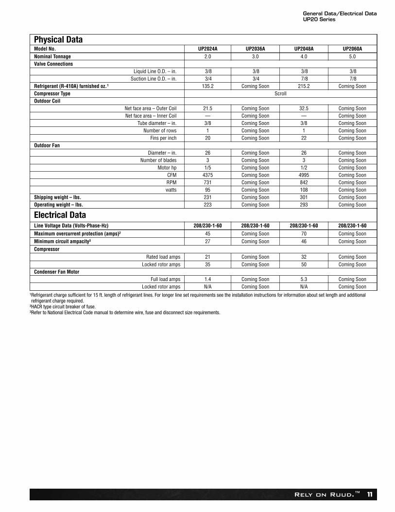
Physical DataModel No. UP2024A UP2036A UP2048A UP2060ANominal Tonnage 2.0 3.0 4.0 5.0Valve Connections
Liquid Line O.D. – in. 3/8 3/8 3/8 3/8Suction Line O.D. – in. 3/4 3/4 7/8 7/8
Refrigerant (R-410A) furnished oz.¹ 135.2 Coming Soon 215.2 Coming SoonCompressor Type ScrollOutdoor Coil
Net face area – Outer Coil 21.5 Coming Soon 32.5 Coming SoonNet face area – Inner Coil — Coming Soon — Coming Soon
Tube diameter – in. 3/8 Coming Soon 3/8 Coming SoonNumber of rows 1 Coming Soon 1 Coming Soon
Fins per inch 20 Coming Soon 22 Coming SoonOutdoor Fan
Diameter – in. 26 Coming Soon 26 Coming SoonNumber of blades 3 Coming Soon 3 Coming Soon
Motor hp 1/5 Coming Soon 1/2 Coming SoonCFM 4375 Coming Soon 4995 Coming SoonRPM 731 Coming Soon 842 Coming Soonwatts 95 Coming Soon 108 Coming Soon
Shipping weight – lbs. 231 Coming Soon 301 Coming SoonOperating weight – lbs. 223 Coming Soon 293 Coming Soon
Electrical DataLine Voltage Data (Volts-Phase-Hz) 208/230-1-60 208/230-1-60 208/230-1-60 208/230-1-60
Maximum overcurrent protection (amps)² 45 Coming Soon 70 Coming SoonMinimum circuit ampacity³ 27 Coming Soon 46 Coming SoonCompressor
Rated load amps 21 Coming Soon 32 Coming SoonLocked rotor amps 35 Coming Soon 50 Coming Soon
Condenser Fan MotorFull load amps 1.4 Coming Soon 5.3 Coming Soon
Locked rotor amps N/A Coming Soon N/A Coming Soon
¹Refrigerant charge sufficient for 15 ft. length of refrigerant lines. For longer line set requirements see the installation instructions for information about set length and additionalrefrigerant charge required.
²HACR type circuit breaker of fuse.³Refer to National Electrical Code manual to determine wire, fuse and disconnect size requirements.
Accessories/Weighted Sound PowerUP20 Series
Rely on Ruud.™12
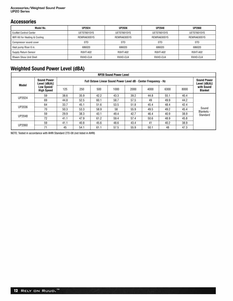
AccessoriesModel No. UP2024 UP2036 UP2048 UP2060
EcoNet Control Center UETST601SYS UETST601SYS UETST601SYS UETST601SYS
WiFi Kit for Heating & Cooling REWRA630SYS REWRA630SYS REWRA630SYS REWRA630SYS
Compressor sound cover STD STD STD STD
Heat pump Riser 6 in. 686020 686020 686020 686020
Supply Return Sensor RXHT-A02 RXHT-A02 RXHT-A02 RXHT-A02
Rheem Show Unit Shell RXHD-CU4 RXHD-CU4 RXHD-CU4 RXHD-CU4
Weighted Sound Power Level (dBA)RP20 Sound Power Level
Model
Sound PowerLevel [dB(A)]Low Speed/High Speed
Full Octave Linear Sound Power Level dB - Center Frequency - Hz Sound PowerLevel [dB(A)]with Sound
Blanket125 250 500 1000 2000 4000 6300 8000
UP202459 38.6 35.9 42.2 43.3 39.2 44.8 55.1 40.4
Sound Blankets -Standard
69 44.8 52.5 60.1 58.7 57.5 49 49.9 44.2
UP203664 33.7 45.1 51.6 53.5 51.8 45.4 48.4 42.470 50.3 53.3 58.9 58 55.9 49.5 49.2 45.4
UP204859 29.9 38.3 43.1 49.4 42.7 46.4 40.9 38.972 41.1 47.9 61.2 59.4 57.4 50.6 48.9 45.8
UP206059 41.1 40.8 45.6 48.6 43.4 41 40.2 38.971 45 54.1 61.1 57.5 55.9 50.1 48 47.3
NOTE: Tested in accordance with AHRI Standard 270-08 (not listed in AHRI)
Smart Home SystemsUP20 Series
Rely on Ruud.™ 13
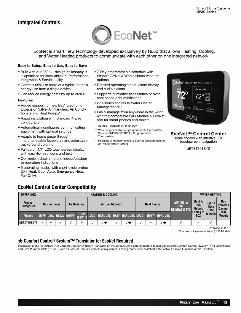
Easy to Setup, Easy to Use, Easy to Save
• Built with our 360°+1 design philosophy, itis optimized for Installability™, Performance,Integration & Serviceability
• Controls 65%† or more of a typical home’senergy use from a single device
• Can reduce energy costs by up to 30%††
Features• Added support for new EEV (Electronic
Expansion Valve) Air Handlers, Air Condi-tioners and Heat Pumps*
• Rapid installation with standard 4-wireconfiguration
• Automatically configures communicatingequipment with optimal settings
• Adapts to home décor throughinterchangeable faceplates and adjustablebackground coloring
• Full-color, 4.7" LCD touchscreen displaywith easy-to-read icons and text
• Convenient date, time and indoor/outdoortemperature indications
• 5 operating modes with short-cycle protec-tion (Heat, Cool, Auto, Emergency Heat,Fan Only)
• 7-Day programmable schedule withSmooth Arrival & Whole Home Vacationoptions
• Detailed operating status, alarm history,and audible alerts
• Supports humidifier accessories or over-cool based dehumidification
• One-touch access to Water Heater Management†††
• Easily manage from anywhere in the worldwith the compatible WiFi Module & EcoNetapp for smart phones and tablets
††† Source – Department of Energy ††† When compared to non-programmable thermostats.
Source: ENERGY STAR® for ProgrammableThermostats
††† Requires wired connection to EcoNet Enabled Electricor Hybrid Water Heaters
Integrated Controls
EcoNet is smart, new technology developed exclusively by Ruud that allows Heating, Cooling,and Water Heating products to communicate with each other on one integrated network.
EcoNet™ Control CenterHome control with intuitive LCD
touchscreen navigation
UETST601SYS
EcoNet Control Center Compatibility
★ Comfort Control2 System™ Translator for EcoNet RequiredInstallation of the RETRN620CC2 Comfort Control2 System™ Translator on the outdoor unit’s control board is required to operate Comfort Control2 System™ Air Conditionerand Heat Pump models (****-JEC) with an EcoNet Control Center in a fully communicating mode when matched with EcoNet Enabled Furnaces or Air Handlers*.
OFFERINGS HEATING & COOLING
WiFi Kit forHVAC
REWRA630SYS
WATER HEATING
ProductCategories Gas Furnaces Air Handlers Air Conditioners Heat Pumps
ElectricTank
ModelsEnding in
EC2
HybridTankHB50
Models
GasPoweredDamper
TankModelsModels U97V U96V U802V RHMV* RH2T
(EEV**) UA20* UASL-JEC UA17 UARL-JEC UP20* UP17* UPRL-JEC
UETST601SYS √ √ √ √ √ √ √ ★ √ √ ★ √ √ √ ★ √ √ √
*Available in 2016**Electronic Expansion Valve (EEV) Models
Smart Home SystemsUP20 Series
Rely on Ruud.™14
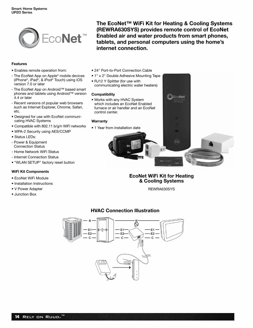
Features
• Enables remote operation from:- The EcoNet App on Apple® mobile devices
(iPhone®, iPad®, & iPod® Touch) using iOSversion 7.0 or later
- The EcoNet App on Android™ based smartphones and tablets using Android™ version4.4 or later
- Recent versions of popular web browserssuch as Internet Explorer, Chrome, Safari,etc.
• Designed for use with EcoNet communi-cating HVAC Systems
• Compatible with 802.11 b/g/n WiFi networks• WPA-2 Security using AES/CCMP• Status LEDs:- Power & Equipment
Connection Status- Home Network WiFi Status- Internet Connection Status• “WLAN SETUP" factory reset button
WiFi Kit Components
• EcoNet WiFi Module• Installation Instructions• V Power Adapter• Junction Box
• 24" Port-to-Port Connection Cable• 1" x 2" Double Adhesive Mounting Tape• RJ12 Y Splitter (for use with
communicating electric water heaters)
Compatibility• Works with any HVAC System
which includes an EcoNet Enabled furnace or air handler and an EcoNet control center.
Warranty
• 1 Year from installation date
The EcoNet™ WiFi Kit for Heating & Cooling Systems(REWRA630SYS) provides remote control of EcoNetEnabled air and water products from smart phones,tablets, and personal computers using the home’sinternet connection.
EcoNet WiFi Kit for Heating& Cooling Systems
REWRA630SYS
HVAC Connection Illustration
Unit DimensionsUP20 Series
Rely on Ruud.™ 15
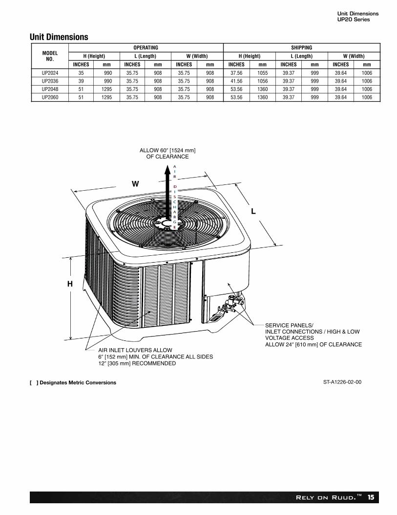
Unit Dimensions
MODELNO.
OPERATING SHIPPING
H (Height) L (Length) W (Width) H (Height) L (Length) W (Width)
INCHES mm INCHES mm INCHES mm INCHES mm INCHES mm INCHES mm
UP2024 35 990 35.75 908 35.75 908 37.56 1055 39.37 999 39.64 1006
UP2036 39 990 35.75 908 35.75 908 41.56 1056 39.37 999 39.64 1006
UP2048 51 1295 35.75 908 35.75 908 53.56 1360 39.37 999 39.64 1006
UP2060 51 1295 35.75 908 35.75 908 53.56 1360 39.37 999 39.64 1006
[ ] Designates Metric Conversions ST-A1226-02-00
ClearancesUP20 Series
Rely on Ruud.™16
6�
(152
.4)
24�
(609
.6)
Ser
vice
12�
(304
.8)
6�
(152
.4)
24�
(609
.6)
Ser
vice
24�
(609
.6)
24�
reco
mm
ende
d6�
min
imum
12�
(304
.8)
12�
(304
.8)
6�
(152
.4)
24�
(609
.6)
Ser
vice
24�
(609
.6)
Ser
vice
24�
(609
.6)
Ser
vice
18�
(457
.2)
WA
LL
WA
LL
WA
LLWALL
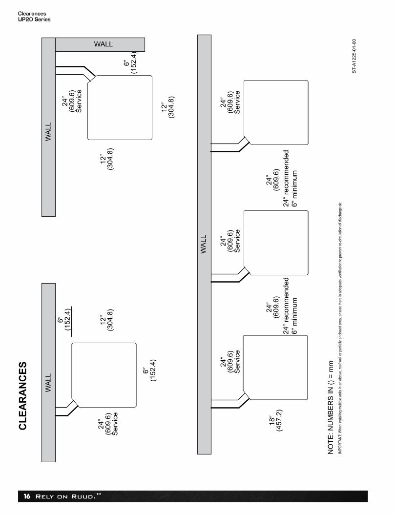
NO
TE
: NU
MB
ER
S IN
()
= m
m
CLEARANCES
IMPO
RTA
NT:
Whe
n in
stal
ling
mul
tiple
uni
ts in
an
alco
ve, r
oof w
ell o
r par
tially
enc
lose
d ar
ea, e
nsur
e th
ere
is a
dequ
ate
vent
illatio
n to
pre
vent
re-c
ircul
atio
n of
dis
char
ge a
ir.
ST-
A12
25-0
1-00
24�
(609
.6)
24�
reco
mm
ende
d6�
min
imum
Rely on Ruud.™ 17
Wiring Diagram/Application GuidelinesUP20 Series
Indoor Unit
E1
E2
C
R
WIRING INFORMATIONLine Voltage –Field Installed - - - - - - –Factory Standard
E1 E2 R C
E1
E2
R
C
Communicating Thermostat
Outdoor Unit
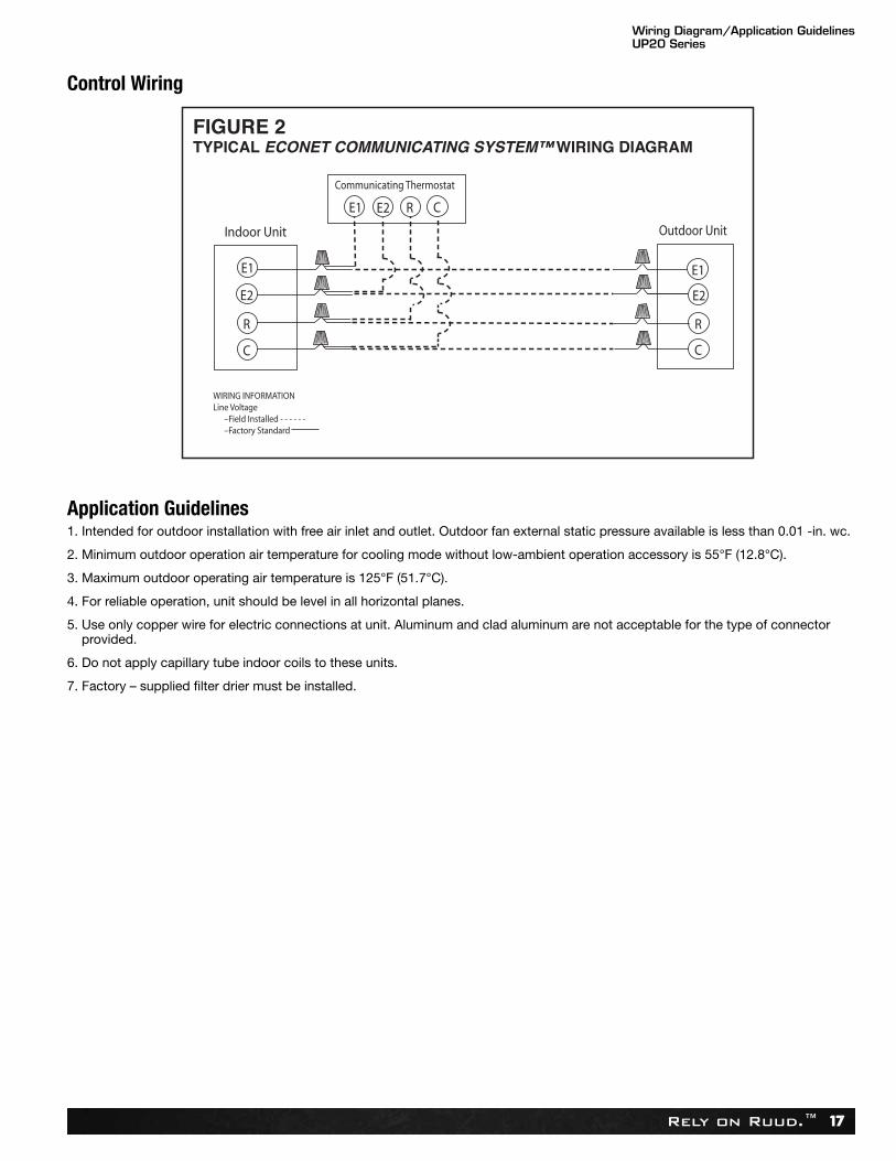
FIGURE 2TYPICAL ECONET COMMUNICATING SYSTEM™ WIRING DIAGRAM
Application Guidelines1. Intended for outdoor installation with free air inlet and outlet. Outdoor fan external static pressure available is less than 0.01 -in. wc.
2. Minimum outdoor operation air temperature for cooling mode without low-ambient operation accessory is 55°F (12.8°C).
3. Maximum outdoor operating air temperature is 125°F (51.7°C).
4. For reliable operation, unit should be level in all horizontal planes.
5. Use only copper wire for electric connections at unit. Aluminum and clad aluminum are not acceptable for the type of connectorprovided.
6. Do not apply capillary tube indoor coils to these units.
7. Factory – supplied filter drier must be installed.
Control Wiring
Refrigerant Line Size InformationUP20 Series
Rely on Ruud.™18
R-41
0A S
yste
mCa
paci
ty M
odel
Liqu
id L
ine
Size
Conn
ectio
n Si
ze(In
ch I.
D.) [
mm
]
Liqu
id L
ine
Size
(Inch
O.D
.) [m
m]
Liqu
id L
ine
Sele
ctio
n Ch
art
Elev
atio
n (A
bove
or B
elow
) Ind
oor C
oil
Tota
lEqu
ival
ent L
engt
h - F
eet [
m]
25 [7
.62]
50 [1
5.24
]75
[22.
86]
100
[30.
48]
125
[45.
72]
150
[45.
72]
175
[53.
34]
200
[60.
96]
225
[68.
58]
250
[76.
20]
275
[83.
82]
300
[91.
44]
Max
imum
Ver
tical
Sep
arat
ion
–Fe
et [m
]
243/
8" [9
.53]
1/4
[6.
35]
25 [7
.62]
50 [1
5.24
]35
[10.
67]
15
[4.5
7]N/
RN/
RN/
RN/
RN/
RN/
RN/
RN/
R5/
16
[7.9
4]25
[7.6
2]50
[15.
24]
75 [2
2.86
]80
[24.
38]
75 [2
2.86
]70
[21.
34]
60 [1
8.29
]55
[16.
76]
50 [1
5.24
]45
[13.
72]
40 [1
2.19
]35
[10.
67]
3/8
[9.5
3]25
[7.6
2]50
[15.
24]
75 [2
2.86
]95
[28.
96]
90 [2
7.43
]90
[27.
43]
90 [2
7.43
]85
[25.
91]
85 [2
5.91
]80
[24.
38]
80 [2
4.38
]80
[24.
38]
7/16
[11.
12]
25 [7
.62]
50 [1
5.24
]75
[22.
86]
100
[30.
48]
95 [2
8.96
]95
[28.
96]
95 [2
8.96
]95
[28.
96]
95 [2
8.96
]95
[28.
96]
90 [2
7.43
]90
[27.
43]
1/2
[12.
71]
25 [7
.62]
50 [1
5.24
]75
[22.
86]
100
[30.
48]
100
[30.
48]
100
[30.
48]
100
[30.
48]
100
[30.
48]
100
[30.
48]
100
[30.
48]
95 [2
8.96
]95
[28.
96]
363/
8" [9
.53]
1/4
[6.
35]
25 [7
.62]
N/R
N/R
N/R
N/R
N/R
N/R
N/R
N/R
N/R
N/R
N/R
5/16
[7
.94]
25 [7
.62]
50 [1
5.24
]60
[18.
29]
45 [1
3.72
]30
[9
.14]
20
[6.1
]5
[1
.52]
N/R
N/R
N/R
N/R
N/R
3/8
[9.5
3]25
[7.6
2]50
[15.
24]
75 [2
2.86
]80
[24.
38]
75 [2
2.86
]70
[21.
34]
65 [1
9.81
]60
[18.
29]
55 [1
6.76
]50
[15.
24]
50 [1
5.24
]45
[13.
72]
7/16
[11.
12]
25 [7
.62]
50 [1
5.24
]75
[22.
86]
90 [2
7.43
]90
[27.
43]
85 [2
5.91
]85
[25.
91]
80 [2
4.38
]80
[24.
38]
80 [2
4.38
]75
[22.
86]
75 [2
2.86
]1/
2 [1
2.71
]25
[7.6
2]50
[15.
24]
75 [2
2.86
]95
[28.
96]
95 [2
8.96
]90
[27.
43]
90 [2
7.43
]90
[27.
43]
90 [2
7.43
]90
[27.
43]
85 [2
5.91
]85
[25.
91]
483/
8" [9
.53]
1/4
[6.
35]
20 [6
.1]
N/R
N/R
N/R
N/R
N/R
N/R
N/R
N/R
N/R
N/R
N/R
5/16
[7
.94]
25 [7
.62]
50 [1
5.24
]35
[10.
67]
20
[6.
1]N/
RN/
RN/
RN/
RN/
RN/
RN/
RN/
R3/
8 [9
.53]
25 [7
.62]
50 [1
5.24
]70
[21.
34]
65 [1
9.81
]60
[18.
29]
55 [1
6.76
]50
[15.
24]
40 [1
2.19
]35
[10.
67]
30
[9.1
4]25
[7
.62]
20
[6.1
]7/
16 [1
1.12
]25
[7.6
2]50
[15.
24]
75 [2
2.86
]80
[24.
38]
75 [2
2.86
]75
[22.
86]
70 [2
1.34
]70
[21.
34]
65 [1
9.81
]65
[19.
81]
60 [1
8.29
]60
[18.
29]
1/2
[12.
71]
25 [7
.62]
50 [1
5.24
]75
[22.
86]
85 [2
5.91
]85
[25.
91]
80 [2
4.38
]80
[24.
38]
80 [2
4.38
]80
[24.
38]
75 [2
2.86
]75
[22.
86]
75 [2
2.86
]
603/
8" [9
.53]
1/4
[6.
35]
N/R
N/R
N/R
N/R
N/R
N/R
N/R
N/R
N/R
N/R
N/R
N/R
5/16
[7
.94]
25 [7
.62]
10
[3.0
5]N/
RN/
RN/
RN/
RN/
RN/
RN/
RN/
RN/
RN/
R3/
8 [9
.53]
25 [7
.62]
50 [1
5.24
]40
[12.
19]
30
[9.1
4]20
[
6.1]
10
[3.0
5]N/
RN/
RN/
RN/
RN/
RN/
R7/
16 [1
1.12
]25
[7.6
2]50
[15.
24]
60 [1
8.29
]55
[16.
76]
50 [1
5.24
]45
[13.
72]
40 [1
2.19
]35
[10.
67]
35 [1
0.67
]30
[9
.14]
25
[7.6
2]20
[
6.1]
1/2
[12.
71]
25 [7
.62]
50 [1
5.24
]65
[19.
81]
65 [1
9.81
]60
[18.
29]
60 [1
8.29
]55
[16.
76]
55 [1
6.76
]55
[16.
76]
50 [1
5.24
]50
[15.
24]
45 [1
3.72
]
Refr
iger
ant L
ine
Size
Info
rmat
ion
NOTE
S:[
] D
esig
nate
s M
etri
c C
onv
ersi
ons
N/R
= A
pplic
atio
n no
t rec
omm
ende
d.Gr
ey=
This
app
licat
ion
is a
ccep
tabl
e, b
ut th
e lo
ng li
ne g
uide
lines
mus
t be
follo
wed
. Ref
eren
ce L
ong
Line
Set
sec
tion
in th
e I&
O
NEW TABLE TO COME
Refrigerant Line Size InformationUP20 Series
Rely on Ruud.™ 19
R-41
0A S
yste
mCa
paci
ty M
odel
Vapo
r Lin
eCo
nnec
tion
Size
(Inch
I.D.
) [m
m]
Vapo
r Lin
e Si
ze(In
ch O
.D.)
[mm
]
Vapo
r Lin
e Se
lect
ion
Char
tCa
paci
ty M
ultip
lier T
able
Tota
lEqu
ival
ent L
engt
h - F
eet [
m]
25 [7
.62]
50 [1
5.24
]75
[22.
86]
100
[30.
48]
125
[45.
72]
150
[45.
72]
175
[53.
34]
200
[60.
96]
225
[68.
58]
250
[76.
20]
275
[83.
82]
300
[91.
44]
243/
4" [1
9.06
]
5/8
[15.
88]
0.99
0.99
0.98
0.97
0.96
0.96
0.94
0.93
0.92
0.91
0.9
0.9
3/4
[19.
05]
1.00
1.00
1.00
0.99
0.99
0.99
0.99
0.98
0.98
0.98
0.97
0.97
7/8
[22.
23]
N/R
N/R
N/R
N/R
N/R
N/R
N/R
N/R
N/R
N/R
N/R
N/R
1 [
25.4
]N/
RN/
RN/
RN/
RN/
RN/
RN/
RN/
RN/
RN/
RN/
RN/
R1-
1/8
[28.
58]
N/R
N/R
N/R
N/R
N/R
N/R
N/R
N/R
N/R
N/R
N/R
N/R
363/
4" [1
9.06
]
5/8
[15.
88]
0.98
0.96
0.94
0.92
0.9
0.89
0.87
0.85
0.84
0.83
0.84
0.82
3/4
[19.
05]
1.00
0.99
0.98
0.98
0.97
0.96
0.95
0.94
0.94
0.93
0.93
0.92
7/8
[22.
23]
N/R
N/R
N/R
N/R
N/R
N/R
N/R
N/R
N/R
N/R
N/R
N/R
1 [
25.4
]N/
RN/
RN/
RN/
RN/
RN/
RN/
RN/
RN/
RN/
RN/
RN/
R1-
1/8
[28.
58]
N/R
N/R
N/R
N/R
N/R
N/R
N/R
N/R
N/R
N/R
N/R
N/R
483/
4" [1
9.06
]
5/8
[15.
88]
0.99
0.98
0.98
0.96
0.95
0.94
0.93
0.92
0.91
0.9
0.89
0.88
3/4
[19.
05]
0.98
0.94
0.91
0.89
0.87
0.84
0.83
0.81
0.8
0.82
0.81
0.83
7/8
[22.
23]
1.00
0.99
0.99
0.98
0.98
0.97
0.98
0.97
0.97
0.96
0.95
0.95
1 [
25.4
]N/
RN/
RN/
RN/
RN/
RN/
RN/
RN/
RN/
RN/
RN/
RN/
R1-
1/8
[28.
58]
N/R
N/R
N/R
N/R
N/R
N/R
N/R
N/R
N/R
N/R
N/R
N/R
603/
4" [1
9.06
]
5/8
[15.
88]
0.99
0.98
0.96
0.95
0.94
0.92
N/R
N/R
N/R
N/R
N/R
N/R
3/4
[19.
05]
0.97
0.93
0.89
0.87
0.84
0.83
N/R
N/R
N/R
N/R
N/R
N/R
7/8
[22.
23]
1.00
0.99
0.99
0.98
0.98
0.97
N/R
N/R
N/R
N/R
N/R
N/R
1 [
25.4
]N/
RN/
RN/
RN/
RN/
RN/
RN/
RN/
RN/
RN/
RN/
RN/
R1-
1/8
[28.
58]
N/R
N/R
N/R
N/R
N/R
N/R
N/R
N/R
N/R
N/R
N/R
N/R
Refr
iger
ant L
ine
Size
Info
rmat
ion
(con
’t.)
NOTE
S:[
] D
esig
nate
s M
etri
c C
onv
ersi
ons
N/R
= A
pplic
atio
n no
t rec
omm
ende
d.Al
l cal
cula
tions
ass
ume
a 3/
8" li
quid
line
NEW TABLE TO COME
Performance DataUP20 Series
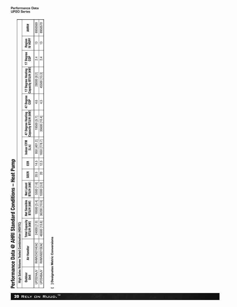
Rely on Ruud.™20
Perf
orm
ance
Dat
a @
AHR
I Sta
ndar
d Co
nditi
ons
–He
at P
ump
High
Sal
es V
olum
e Te
sted
Com
bina
tion
(HSV
TC)
Outd
oor
Unit
Air H
andl
erTo
tal C
apac
ityBT
U/H
[kW
]Ne
t Sen
sibl
eBT
U/H
[kW
]Ne
t Lat
ent
BTU/
H [k
W]
SEER
EER
Indo
or C
FM[L
/s]
47 D
egre
e He
atin
gCa
paci
ty B
TU/H
[kW
]47
Deg
ree
COP
17 D
egre
e He
atin
gCa
paci
ty B
TU/H
[kW
]17
Deg
ree
COP
Regi
onIV
HSP
FAH
RI#
UP20
24AJ
VRH
MV2
421H
EAC
2400
0 [7
.0]
1850
0 [5
.4]
5500
[1.6
]20
.514
.585
0 [4
01.2
]19
500
[5.7
]4.
628
000
[8.2
]2.
413
8950
569
UP20
48AJ
VRH
MV6
021S
EAC
4650
0 [1
3.6]
3620
0 [1
0.6]
1030
0 [3
.0]
2012
.516
50 [7
78.7
]35
600
[10.
4]4.
545
500
[13.
3]2.
413
8950
570
[ ]
Des
igna
tes
Met
ric
Co
nver
sio
ns
Guide SpecificationsUP20 Series
Rely on Ruud.™ 21
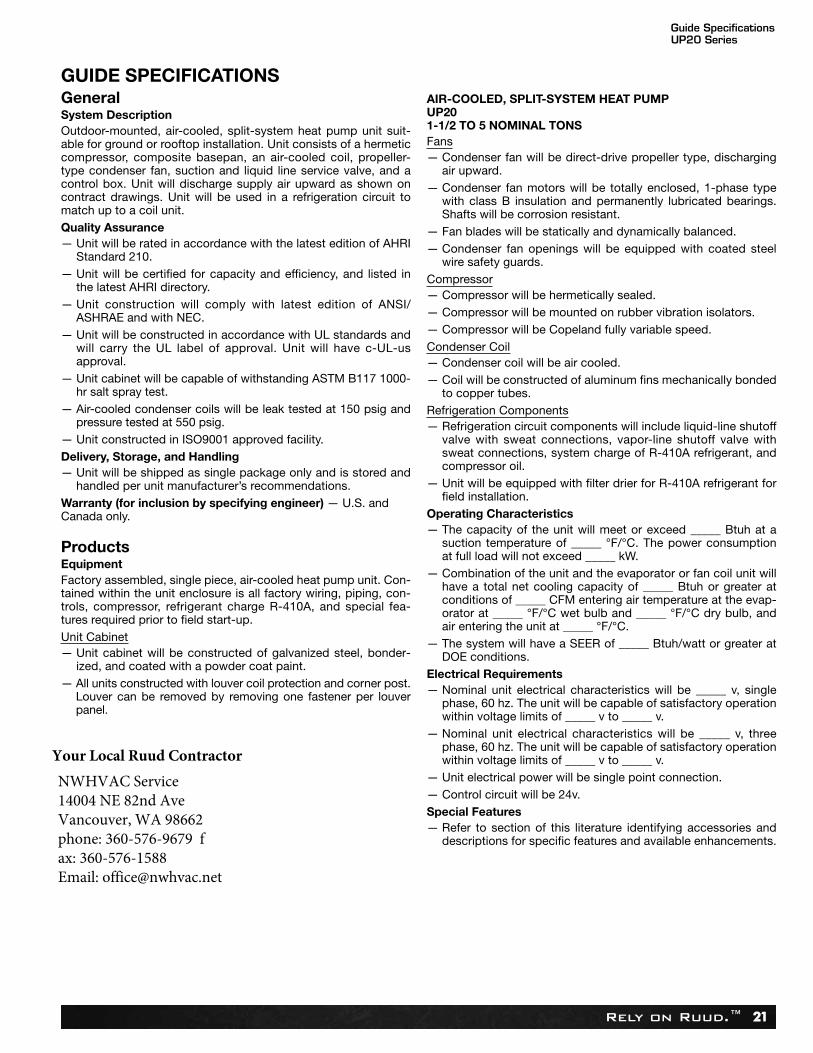
GUIDE SPECIFICATIONS GeneralSystem DescriptionOutdoor-mounted, air-cooled, split-system heat pump unit suit-able for ground or rooftop installation. Unit consists of a hermeticcompressor, composite basepan, an air-cooled coil, propeller-type condenser fan, suction and liquid line service valve, and acontrol box. Unit will discharge supply air upward as shown oncontract drawings. Unit will be used in a refrigeration circuit tomatch up to a coil unit.Quality Assurance— Unit will be rated in accordance with the latest edition of AHRI
Standard 210.— Unit will be certified for capacity and efficiency, and listed in
the latest AHRI directory.— Unit construction will comply with latest edition of ANSI/
ASHRAE and with NEC.— Unit will be constructed in accordance with UL standards and
will carry the UL label of approval. Unit will have c-UL-usapproval.
— Unit cabinet will be capable of withstanding ASTM B117 1000-hr salt spray test.
— Air-cooled condenser coils will be leak tested at 150 psig andpressure tested at 550 psig.
— Unit constructed in ISO9001 approved facility. Delivery, Storage, and Handling— Unit will be shipped as single package only and is stored and
handled per unit manufacturer’s recommendations.Warranty (for inclusion by specifying engineer) — U.S. andCanada only.
ProductsEquipmentFactory assembled, single piece, air-cooled heat pump unit. Con-tained within the unit enclosure is all factory wiring, piping, con-trols, compressor, refrigerant charge R-410A, and special fea-tures required prior to field start-up.Unit Cabinet— Unit cabinet will be constructed of galvanized steel, bonder-
ized, and coated with a powder coat paint.— All units constructed with louver coil protection and corner post.
Louver can be removed by removing one fastener per louverpanel.
AIR-COOLED, SPLIT-SYSTEM HEAT PUMPUP201-1/2 TO 5 NOMINAL TONSFans— Condenser fan will be direct-drive propeller type, discharging
air upward.— Condenser fan motors will be totally enclosed, 1-phase type
with class B insulation and permanently lubricated bearings.Shafts will be corrosion resistant.
— Fan blades will be statically and dynamically balanced.— Condenser fan openings will be equipped with coated steel
wire safety guards.Compressor— Compressor will be hermetically sealed.— Compressor will be mounted on rubber vibration isolators.— Compressor will be Copeland fully variable speed.Condenser Coil— Condenser coil will be air cooled.— Coil will be constructed of aluminum fins mechanically bonded
to copper tubes.Refrigeration Components— Refrigeration circuit components will include liquid-line shutoff
valve with sweat connections, vapor-line shutoff valve withsweat connections, system charge of R-410A refrigerant, andcompressor oil.
— Unit will be equipped with filter drier for R-410A refrigerant forfield installation.
Operating Characteristics— The capacity of the unit will meet or exceed _____ Btuh at a
suction temperature of _____ °F/°C. The power consumptionat full load will not exceed _____ kW.
— Combination of the unit and the evaporator or fan coil unit willhave a total net cooling capacity of _____ Btuh or greater atconditions of _____ CFM entering air temperature at the evap-orator at _____ °F/°C wet bulb and _____ °F/°C dry bulb, andair entering the unit at _____ °F/°C.
— The system will have a SEER of _____ Btuh/watt or greater atDOE conditions.
Electrical Requirements— Nominal unit electrical characteristics will be _____ v, single
phase, 60 hz. The unit will be capable of satisfactory operationwithin voltage limits of _____ v to _____ v.
— Nominal unit electrical characteristics will be _____ v, threephase, 60 hz. The unit will be capable of satisfactory operationwithin voltage limits of _____ v to _____ v.
— Unit electrical power will be single point connection. — Control circuit will be 24v.Special Features— Refer to section of this literature identifying accessories and
descriptions for specific features and available enhancements.
Your Local Ruud ContractorNWHVAC Service 14004 NE 82nd Ave Vancouver, WA 98662 phone: 360-576-9679 fax: 360-576-1588 Email: [email protected]
Limited WarrantyUP20 Series
Rely on Ruud.™22
GENERAL TERMS OF LIMITED WARRANTY*Ruud will furnish a replacement for any part of this productwhich fails in normal use and service within the applicableperiod stated, in accordance with the terms of the limited warranty.*For complete details of the Limited and Conditional Warranties, includingapplicable terms and conditions, contact your local contractor or theManufacturer for a copy of the product warranty certificate.
Conditional Unit Replacement(Registration Required) ...............................Ten (10) Years
Parts ............................................................Ten (10) Years

NotesUP20 Series
Rely on Ruud.™ 23
Rely on Ruud.™
PRINTED IN U.S.A. 3/16 QG FORM NO. P22-811
Rely on Ruud.™
Ruud Heating, Cooling & Water Heating • P.O. Box 17010Fort Smith, Arkansas 72917 • www.ruud.com
In keeping with its policy of continuous progress and product improvement, Ruud reserves the right to make changes without notice.
Ruud Canada • 125 Edgeware Road, Unit 1Brampton, Ontario • L6Y 0P5