Embed Size (px)
Citation preview
Electric Transformer
Motor Theory
This whole article is written in assumption that the reader has a college level
degree and several years experience with electronics. This document was written with
the intent to define a simple working model and a proof that the theory works on a level
that would allow a high school student to construct a working version of the motor with
this information.
This is the simplest example of a Electric Transformer Motor that is designed to
produce mechanical energy, utilizing Kick EMF to produce it, and operate as a
transformer to recover lost electrical power. Basically, every generator requires 1
mechanical horsepower for every 740 Watts of energy produced. Likewise, an electric
motor requires 740 Watts for every Horsepower. The reason why, is that a certain
amount of power is required to generate a certain number of magnetic lines. Mechanical
as for power generation the magnetic lines are in the form of Kick EMF, whereas with an
electric motor those magnetic lines are keeping the rotor in motion. The more power you
draw, the more magnetic lines create, be that in watts or horses.
If you have walked past a power substation and heard the sound of the
transformers humming, then you have heard the internal magnetic forces playing upon
the core of the transformers. That effect, Kick EMF takes place inside a transformer,
except it is all bound together in one fairly solid structure. So, you can only hear the hum
of the metal and the same rules are still in effect. But, there is a difference. One
transformer with it’s primary produces magnetic lines in the core, the secondary produces
the internal Kick EMF, and converts the magnetic lines back into a voltage and current.
Second, I can take all of the power that wasn’t lost in core materials and winding
resistances, and pass that power on to another transformer to produce nearly the same
number of magnetic lines. That almost doubles the population of magnetic lines
produced by the same AC Power Supply. At the power substation I would see stepping
up the voltages to place the power on a high tension line, and some distance away another
transformer stepping the voltage down. The efficiency of the transformer is the only real
concern.
In order for this circuit/motor to function both as a motor and a transformer, the
motor is dependant on the secondary of the transformer being shorted to maintain a
maximum output of mechanical energy watt per watt. At a power substation, if the short
circuit is 100 miles, and through several power substations and transformers, all of the
transformers in line with generator draw more current, produce more magnetic lines, and
the power surge is felt at the generator. In order to attain the maximum amount of
mechanical energy, the core must also approach saturation cycle per cycle of AC power
applied and peak with nearly the maximum number of magnetic lines the core material is
capable of retaining. Anything beyond the core material is wasted energy because, the
windings start to act as an air core coil, and the amount of energy literally required to
produce mechanical energy is well outside of the 740 Watts per Horsepower range.
In order for the motor to really operate at it’s maximum mechanical potential, the
secondary must appear shorted to the primary. Electronically, it’s just a rotating
transformer, and the same rules apply to loading frequencies for a transformer. Placing a
resistive load on the secondary will decrease the amount of mechanical energy produced
by the motor, and it should keep spinning under a array of loads. If it takes less than
gram of energy to make it spin, it will spin as long as the magnetic fields can defeat 1
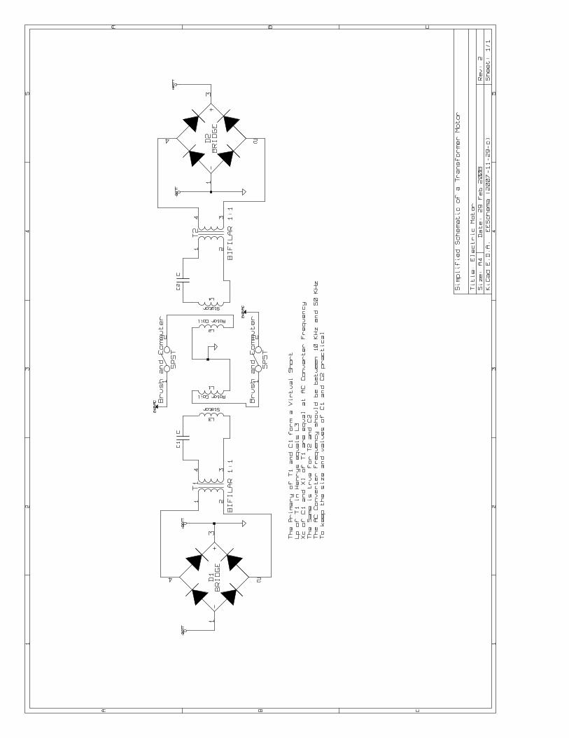
gram of resistance to motion. The diodes can allow you to use a LED to see that there is
power on the secondary, or a small light bulb directly across the secondary/stator coils
without the support circuitry shown in the schematic. If you take the light bulb out of the
circuit the motor will stop when the secondary winding are open, and run when they are
loaded.
Longer rectangular windings will bring up the efficiency of the motor as a
transformer and it’s efficiency will approach 98%. But, this little demo should only
approach 50% efficiency as a transformer, and it’s really just a demo do nothing, that’s
easy to build.

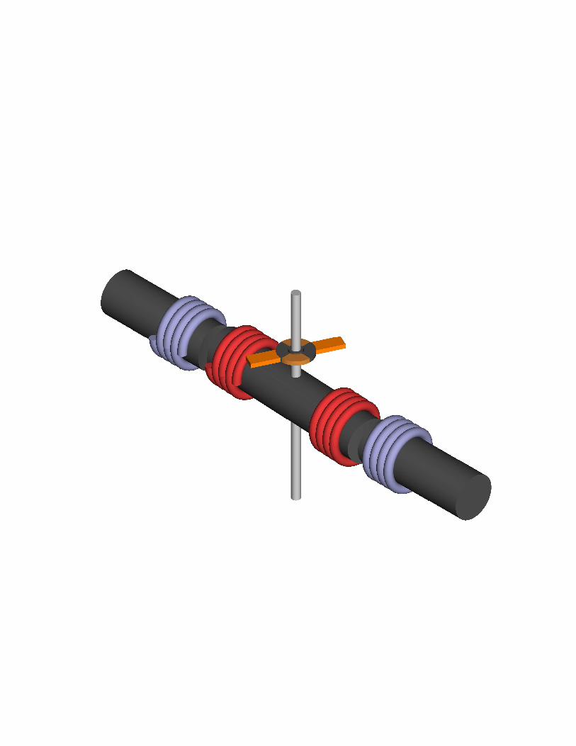
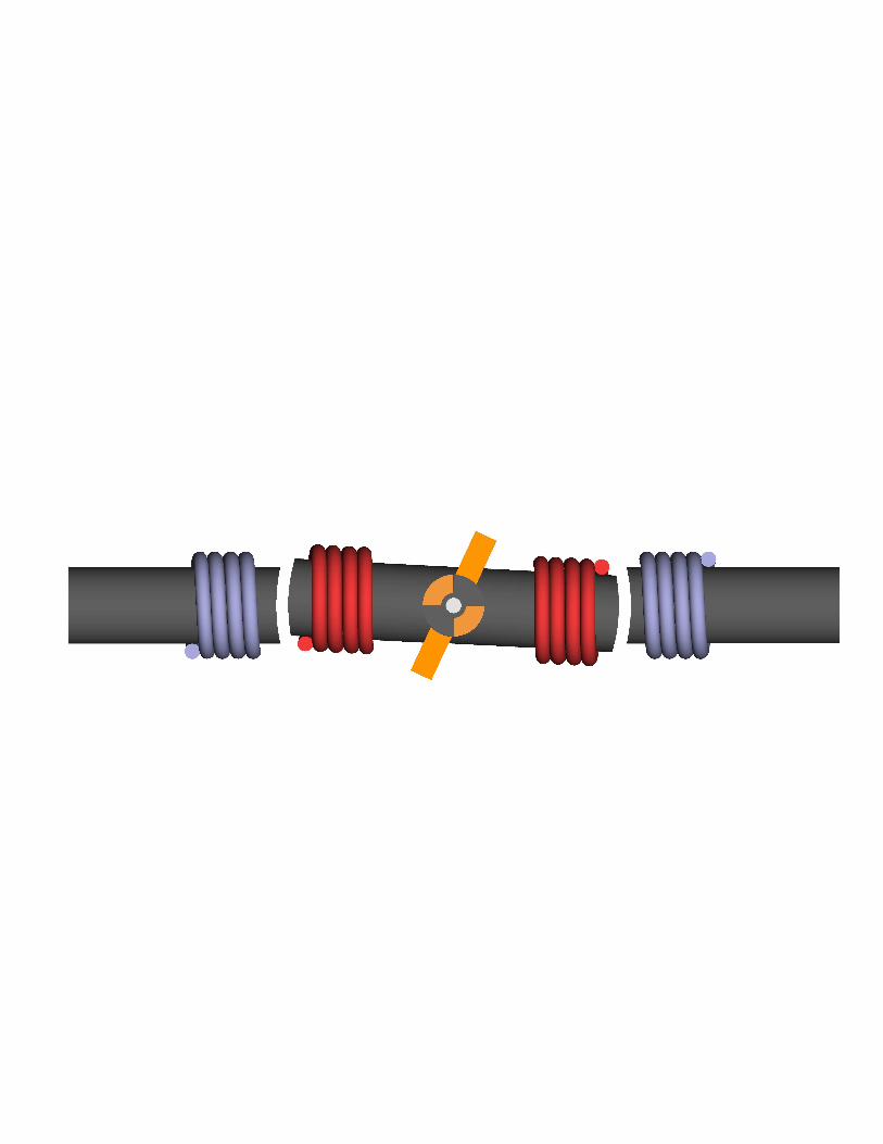
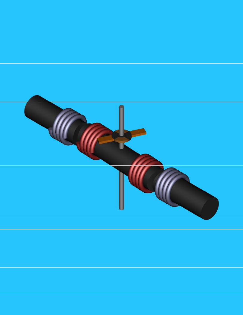
Looking at the graphic the two blue coils are stationary secondary winding placed
on the stator. The two red coils are each connected to the armature and the axis of
rotation as ground. Drawing coils and making mechanical connections with my 3D is a
bit too tedious. The brushes are set at 65° the armature is set at 0°�and the rotor is set at
(-3°). Using an AC source of power, the Kick EMF will not go away and the closer the
secondary/stator is to a short circuit the greater the amount of mechanical force that will
be displaced. This works in concert with core saturation. Metglas saturates around 1.2 to
1.5 Teslas. Other metals don’t even come close, and for the optimum amount of
mechanical energy out, the maximum number of magnetic lines must be present. Just
below saturation the transformer side can perform this task with very little loss. Properly
designing an electric motor, produces differing winding forms of which most are
rectangular. Inductances will vary based upon the geometry of the winding forms used as
the rotor and stator.
This document is theory only intended to define how it works and what is possible
with it. The brush contact is too long to be efficient with this demo design. The rotor is
constructed for the sake of teaching people how it works, not showing them the most
efficiently designed rotor and stator. This document is intended to allow the largest
number of potential readers to understand the operating theory and principles of the
device, and give them enough information to build a working model that may not even be
50% efficient for the sake of visualization. It bares many similarities to a Squirrel Cage
Electric Motor, with the exception that instead of relying on eddy currents in the rotor,
the rotor produces what would have been eddy current in the stator. The Squirrel Cage
Motor can be viewed as a transformer with a shorted secondary. The stator is the primary
transformer core windings, and the secondary is the rotor. In my motor design theory
instead of leaving the eddy currents to exist around the core materials of the rotor, they
are tapped for power by using brushes and windings. A good demo of a squirrel cage
motor that would run does not appear anything like these three rods that could be used to
explain the operating theory behind a Transformer Motor. As a rule, the best teaching
demo, is not always the best motor. It sorted, simple and easy to dissect with the eyes. It
doesn’t rule out 100s of other possible configurations. It gives you one to understand.
There is no extra energy, it’s a rotating transformer. The Patent Office will not
help you if you label it a Perpetual Motion Machine, or attach a generator to it and label it
an Over Unity Device, or a Zero Point Energy Device. But, if you go in there and apply
for a patent for an electric motor, then that’s all they’ll see. They don’t need to know
where the diodes go, or about the other supporting circuitry that should be attached to it
and/or controlling it. For example, if I short out the secondary, I get the most
horsepower, and when I use a Virtual Short, I still have it. But, all of the energy doesn’t
go back to the battery, it gets lost in the core, and I turned that into get up and go via a
Virtual Short/Series Resonant Circuit. Yes, cruising will be very efficient. So, how
driven can effect battery life, most batteries are only good for few years, and for so many
charges. Again, it won’t make through the patent office any other way except, as a
motor. You want to slip it past them as if you are only competing and not innovating.
Then you can program it so that you must plug it in for the shear sake of insuring that no
one steals it and drives from Canada to Mexico or Brazil non-stop. Most people have to
sleep once every 16 hours, so program it for safety’s sake, and plug it in to reset the
timer. The patent is on the design and construction, measurements etc. So, let the motor
be the motor, or a transformer a transformer, unless it spins, even though you know there
doesn’t have to be a difference. In some ways it is better that they don’t know.
The following is an excerpt from an Issue of Scientific American distributedwithout a copyright in 1887. You can find a copy here with the copyright informationavailable concerning the following.http://www.gutenberg.org/ebooks/11498
SCIENTIFIC AMERICANSUPPLEMENT NO. 601
NEW YORK, JULY 9, 1887Scientific American Supplement. Vol. XXIV, No. 601.
Scientific American established 1845
PHENOMENA OF ALTERNATING CURRENTS.[Footnote: From a paper read before the recent meeting of the American Institute of Electrical Engineers,New York, and reported in the Electrical World.]
By Prof. ELIHU THOMSON.The actions produced and producible by the agency of alternating currents of considerable energy areassuming greater importance in the electric arts. I mean, of course, by the term alternating currents, currentsof electricity reversed at frequent intervals, so that a positive flow is succeeded by a negative flow, and thatagain by a positive flow, such reversals occurring many times in a second, so that the curve of current ofelectromotive force will, if plotted, be a wave line, the amplitude of which is the arithmetical sum of thepositive and negative maxima of current or electromotive force, as the case may be, while a horizontalmiddle line joins the zero points of current or electromotive force.
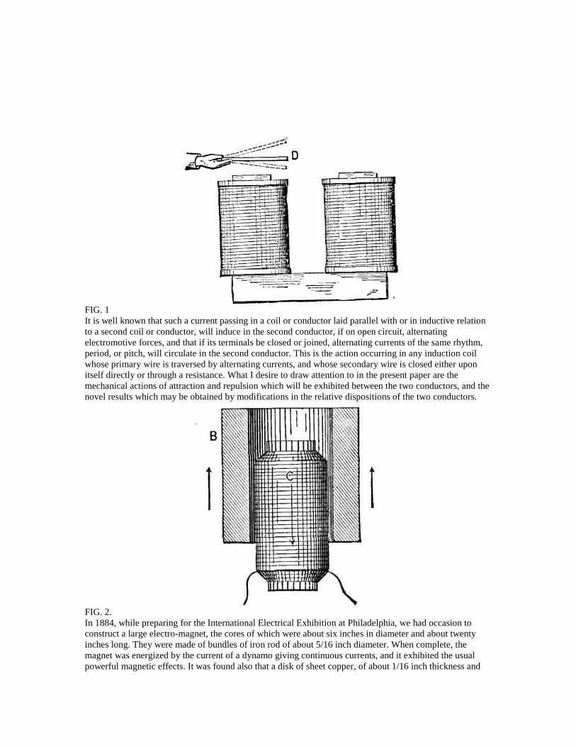
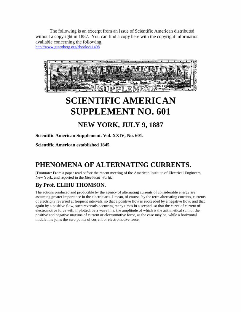
FIG. 1It is well known that such a current passing in a coil or conductor laid parallel with or in inductive relationto a second coil or conductor, will induce in the second conductor, if on open circuit, alternatingelectromotive forces, and that if its terminals be closed or joined, alternating currents of the same rhythm,period, or pitch, will circulate in the second conductor. This is the action occurring in any induction coilwhose primary wire is traversed by alternating currents, and whose secondary wire is closed either uponitself directly or through a resistance. What I desire to draw attention to in the present paper are themechanical actions of attraction and repulsion which will be exhibited between the two conductors, and thenovel results which may be obtained by modifications in the relative dispositions of the two conductors.
FIG. 2.In 1884, while preparing for the International Electrical Exhibition at Philadelphia, we had occasion toconstruct a large electro-magnet, the cores of which were about six inches in diameter and about twentyinches long. They were made of bundles of iron rod of about 5/16 inch diameter. When complete, themagnet was energized by the current of a dynamo giving continuous currents, and it exhibited the usualpowerful magnetic effects. It was found also that a disk of sheet copper, of about 1/16 inch thickness and
10 inches in diameter, if dropped flat against a pole of the magnet, would settle down softly upon it, beingretarded by the development of currents in the disk due to its movement in a strong magnetic field, andwhich currents were of opposite direction to those in the coils of the magnet. In fact, it was impossible tostrike the magnet pole a sharp blow with the disk, even when the attempt was made by holding one edge ofthe disk in the hand and bringing it down forcibly toward the magnet. In attempting to raise the diskquickly off the pole, a similar but opposite action of resistance to movement took place, showing thedevelopment of currents in the same direction to those in the coils of the magnet, and which currents, ofcourse, would cause attraction as a result.
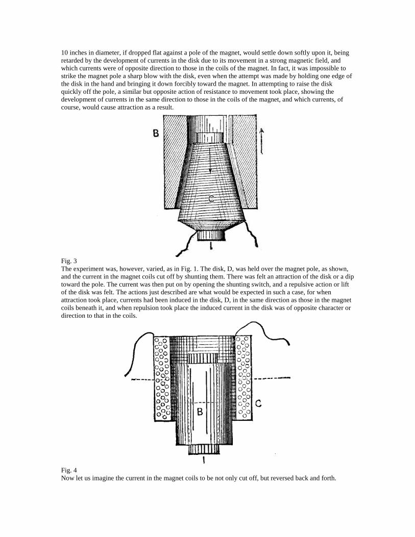
Fig. 3The experiment was, however, varied, as in Fig. 1. The disk, D, was held over the magnet pole, as shown,and the current in the magnet coils cut off by shunting them. There was felt an attraction of the disk or a diptoward the pole. The current was then put on by opening the shunting switch, and a repulsive action or liftof the disk was felt. The actions just described are what would be expected in such a case, for whenattraction took place, currents had been induced in the disk, D, in the same direction as those in the magnetcoils beneath it, and when repulsion took place the induced current in the disk was of opposite character ordirection to that in the coils.
Fig. 4Now let us imagine the current in the magnet coils to be not only cut off, but reversed back and forth.
For the reasons just given, we will find that the disk, D, is attracted and repelled alternately; for, wheneverthe currents induced in it are of the same direction with those in the inducing or magnet coil, attraction willensue, and when they are opposite in direction, repulsion will be produced. Moreover, the repulsion will beproduced when the current in the magnet coil is rising to a maximum in either direction, and attraction willbe the result when the current of either direction is falling to zero, since in the former case opposite currentsare induced in the disk, D, in accordance with well known laws, and in the latter case currents of the samedirection will exist in the disk, D, and the magnet coil. The disk might, of course, be replaced by a ring ofcopper or other good conductor, or by a closed coil of bare or insulated wire, or by a series of disks, ringsor coils superposed, and the results would be the same. Thus far, indeed, we have nothing of a particularlynovel character, and, doubtless, other experimenters have made very similar experiments and noted similarresults to those described.
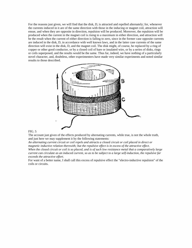
FIG. 5The account just given of the effects produced by alternating currents, while true, is not the whole truth,and just here we may supplement it by the following statements:An alternating current circuit or coil repels and attracts a closed circuit or coil placed in direct ormagnetic inductive relation therewith; but the repulsive effect is in excess of the attractive effect.When the closed circuit or coil is so placed, and is of such low resistance metal that a comparatively largecurrent can circulate as an induced current, so as to be subject to a large self-induction, the repulsive farexceeds the attractive effort.For want of a better name, I shall call this excess of repulsive effect the "electro-inductive repulsion" of thecoils or circuits.
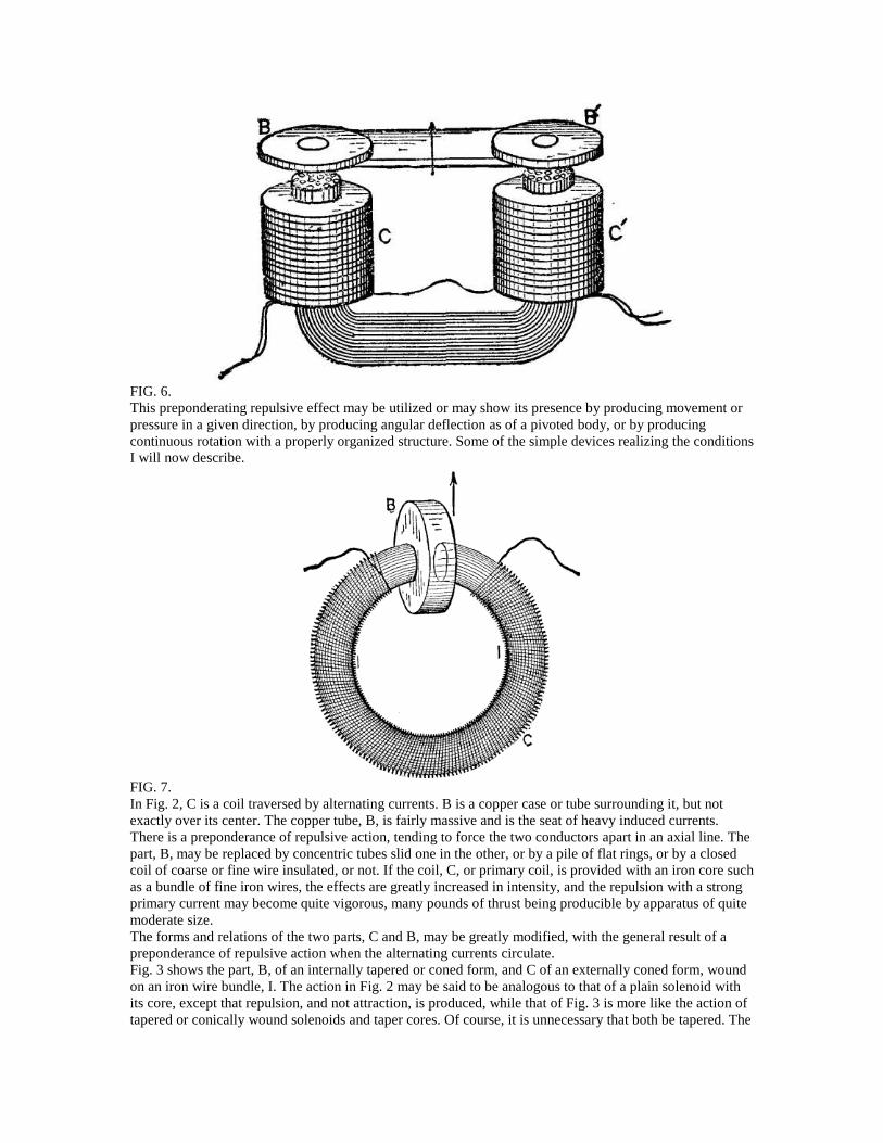
FIG. 6.This preponderating repulsive effect may be utilized or may show its presence by producing movement orpressure in a given direction, by producing angular deflection as of a pivoted body, or by producingcontinuous rotation with a properly organized structure. Some of the simple devices realizing the conditionsI will now describe.
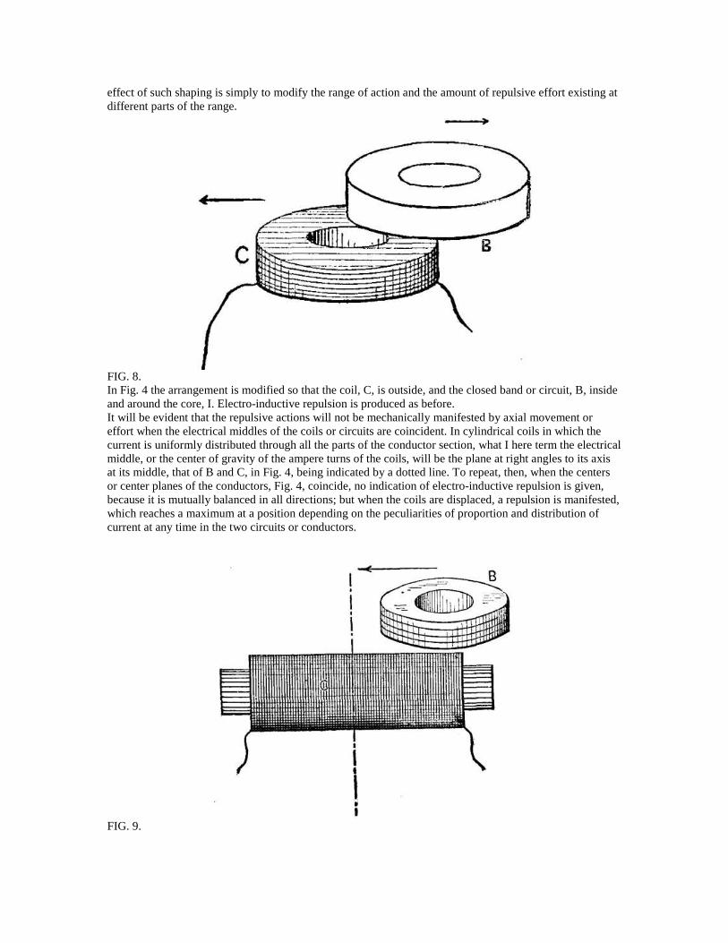
FIG. 7.In Fig. 2, C is a coil traversed by alternating currents. B is a copper case or tube surrounding it, but notexactly over its center. The copper tube, B, is fairly massive and is the seat of heavy induced currents.There is a preponderance of repulsive action, tending to force the two conductors apart in an axial line. Thepart, B, may be replaced by concentric tubes slid one in the other, or by a pile of flat rings, or by a closedcoil of coarse or fine wire insulated, or not. If the coil, C, or primary coil, is provided with an iron core suchas a bundle of fine iron wires, the effects are greatly increased in intensity, and the repulsion with a strongprimary current may become quite vigorous, many pounds of thrust being producible by apparatus of quitemoderate size.The forms and relations of the two parts, C and B, may be greatly modified, with the general result of apreponderance of repulsive action when the alternating currents circulate.Fig. 3 shows the part, B, of an internally tapered or coned form, and C of an externally coned form, woundon an iron wire bundle, I. The action in Fig. 2 may be said to be analogous to that of a plain solenoid withits core, except that repulsion, and not attraction, is produced, while that of Fig. 3 is more like the action oftapered or conically wound solenoids and taper cores. Of course, it is unnecessary that both be tapered. The
effect of such shaping is simply to modify the range of action and the amount of repulsive effort existing atdifferent parts of the range.
FIG. 8.In Fig. 4 the arrangement is modified so that the coil, C, is outside, and the closed band or circuit, B, insideand around the core, I. Electro-inductive repulsion is produced as before.It will be evident that the repulsive actions will not be mechanically manifested by axial movement oreffort when the electrical middles of the coils or circuits are coincident. In cylindrical coils in which thecurrent is uniformly distributed through all the parts of the conductor section, what I here term the electricalmiddle, or the center of gravity of the ampere turns of the coils, will be the plane at right angles to its axisat its middle, that of B and C, in Fig. 4, being indicated by a dotted line. To repeat, then, when the centersor center planes of the conductors, Fig. 4, coincide, no indication of electro-inductive repulsion is given,because it is mutually balanced in all directions; but when the coils are displaced, a repulsion is manifested,which reaches a maximum at a position depending on the peculiarities of proportion and distribution ofcurrent at any time in the two circuits or conductors.
FIG. 9.
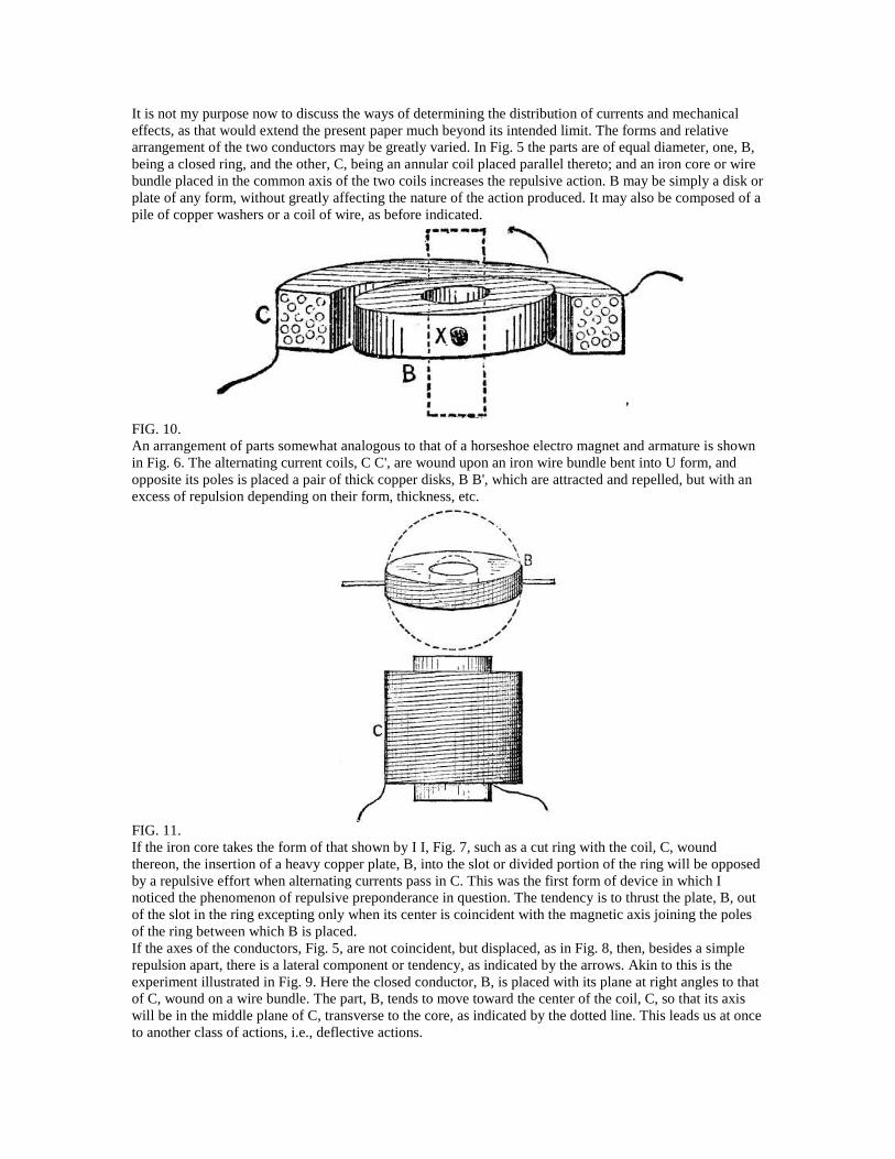
It is not my purpose now to discuss the ways of determining the distribution of currents and mechanicaleffects, as that would extend the present paper much beyond its intended limit. The forms and relativearrangement of the two conductors may be greatly varied. In Fig. 5 the parts are of equal diameter, one, B,being a closed ring, and the other, C, being an annular coil placed parallel thereto; and an iron core or wirebundle placed in the common axis of the two coils increases the repulsive action. B may be simply a disk orplate of any form, without greatly affecting the nature of the action produced. It may also be composed of apile of copper washers or a coil of wire, as before indicated.
FIG. 10.An arrangement of parts somewhat analogous to that of a horseshoe electro magnet and armature is shownin Fig. 6. The alternating current coils, C C', are wound upon an iron wire bundle bent into U form, andopposite its poles is placed a pair of thick copper disks, B B', which are attracted and repelled, but with anexcess of repulsion depending on their form, thickness, etc.
FIG. 11.If the iron core takes the form of that shown by I I, Fig. 7, such as a cut ring with the coil, C, woundthereon, the insertion of a heavy copper plate, B, into the slot or divided portion of the ring will be opposedby a repulsive effort when alternating currents pass in C. This was the first form of device in which Inoticed the phenomenon of repulsive preponderance in question. The tendency is to thrust the plate, B, outof the slot in the ring excepting only when its center is coincident with the magnetic axis joining the polesof the ring between which B is placed.If the axes of the conductors, Fig. 5, are not coincident, but displaced, as in Fig. 8, then, besides a simplerepulsion apart, there is a lateral component or tendency, as indicated by the arrows. Akin to this is theexperiment illustrated in Fig. 9. Here the closed conductor, B, is placed with its plane at right angles to thatof C, wound on a wire bundle. The part, B, tends to move toward the center of the coil, C, so that its axiswill be in the middle plane of C, transverse to the core, as indicated by the dotted line. This leads us at onceto another class of actions, i.e., deflective actions.
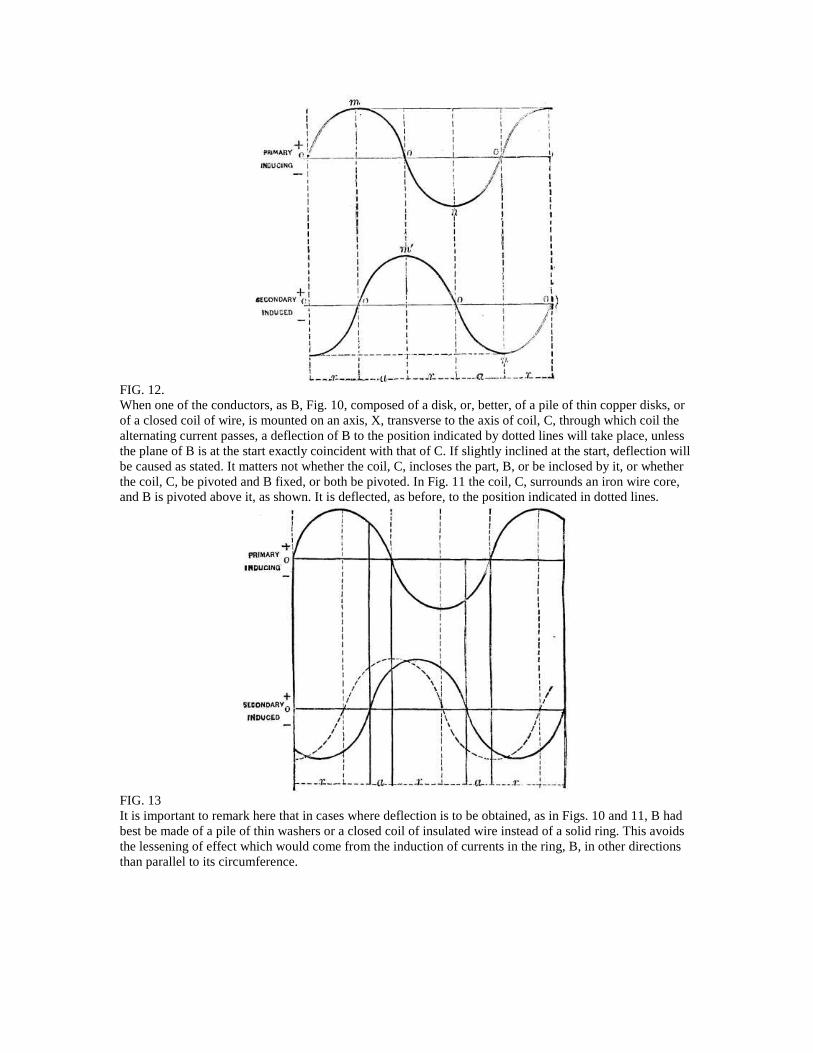
FIG. 12.When one of the conductors, as B, Fig. 10, composed of a disk, or, better, of a pile of thin copper disks, orof a closed coil of wire, is mounted on an axis, X, transverse to the axis of coil, C, through which coil thealternating current passes, a deflection of B to the position indicated by dotted lines will take place, unlessthe plane of B is at the start exactly coincident with that of C. If slightly inclined at the start, deflection willbe caused as stated. It matters not whether the coil, C, incloses the part, B, or be inclosed by it, or whetherthe coil, C, be pivoted and B fixed, or both be pivoted. In Fig. 11 the coil, C, surrounds an iron wire core,and B is pivoted above it, as shown. It is deflected, as before, to the position indicated in dotted lines.
FIG. 13It is important to remark here that in cases where deflection is to be obtained, as in Figs. 10 and 11, B hadbest be made of a pile of thin washers or a closed coil of insulated wire instead of a solid ring. This avoidsthe lessening of effect which would come from the induction of currents in the ring, B, in other directionsthan parallel to its circumference.
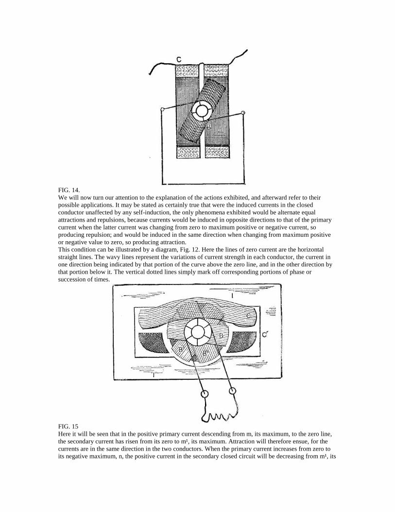
FIG. 14.We will now turn our attention to the explanation of the actions exhibited, and afterward refer to theirpossible applications. It may be stated as certainly true that were the induced currents in the closedconductor unaffected by any self-induction, the only phenomena exhibited would be alternate equalattractions and repulsions, because currents would be induced in opposite directions to that of the primarycurrent when the latter current was changing from zero to maximum positive or negative current, soproducing repulsion; and would be induced in the same direction when changing from maximum positiveor negative value to zero, so producing attraction.This condition can be illustrated by a diagram, Fig. 12. Here the lines of zero current are the horizontalstraight lines. The wavy lines represent the variations of current strength in each conductor, the current inone direction being indicated by that portion of the curve above the zero line, and in the other direction bythat portion below it. The vertical dotted lines simply mark off corresponding portions of phase orsuccession of times.
FIG. 15Here it will be seen that in the positive primary current descending from m, its maximum, to the zero line,the secondary current has risen from its zero to m¹, its maximum. Attraction will therefore ensue, for thecurrents are in the same direction in the two conductors. When the primary current increases from zero toits negative maximum, n, the positive current in the secondary closed circuit will be decreasing from m¹, its
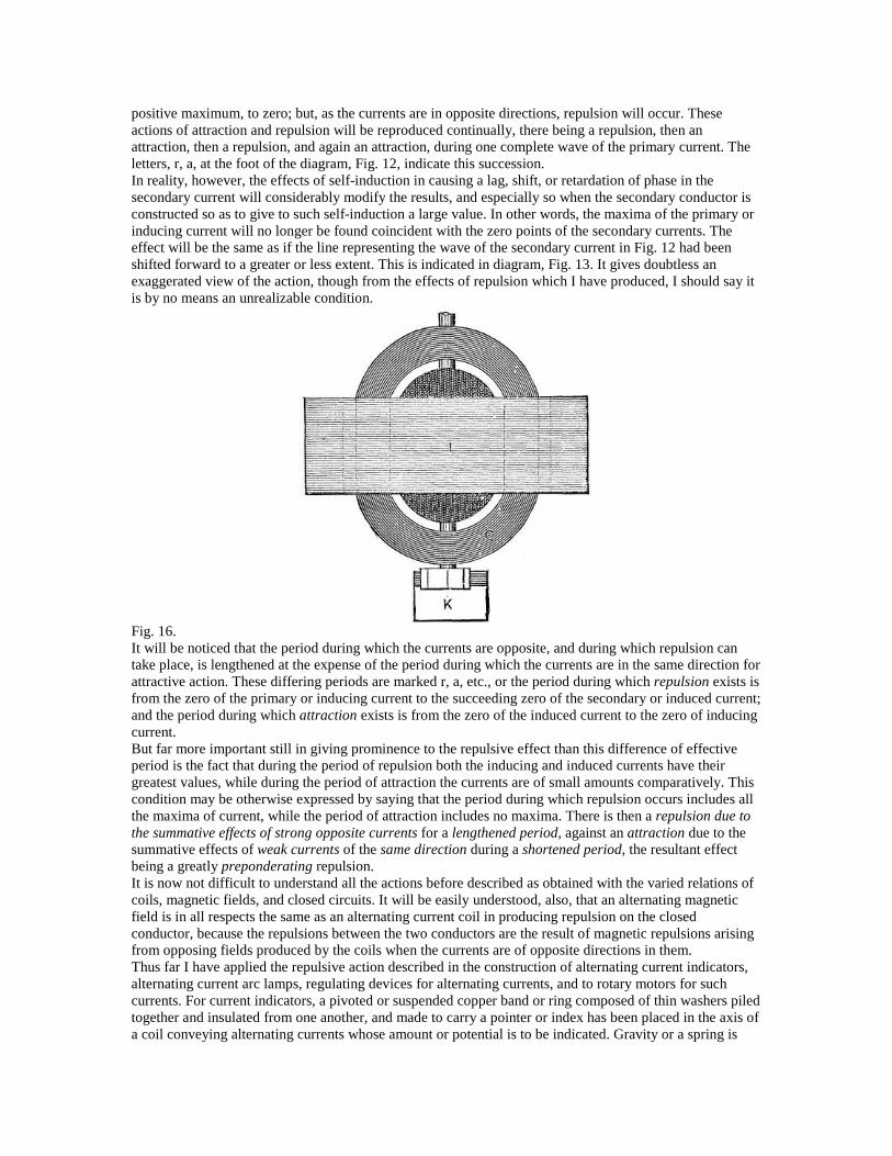
positive maximum, to zero; but, as the currents are in opposite directions, repulsion will occur. Theseactions of attraction and repulsion will be reproduced continually, there being a repulsion, then anattraction, then a repulsion, and again an attraction, during one complete wave of the primary current. Theletters, r, a, at the foot of the diagram, Fig. 12, indicate this succession.In reality, however, the effects of self-induction in causing a lag, shift, or retardation of phase in thesecondary current will considerably modify the results, and especially so when the secondary conductor isconstructed so as to give to such self-induction a large value. In other words, the maxima of the primary orinducing current will no longer be found coincident with the zero points of the secondary currents. Theeffect will be the same as if the line representing the wave of the secondary current in Fig. 12 had beenshifted forward to a greater or less extent. This is indicated in diagram, Fig. 13. It gives doubtless anexaggerated view of the action, though from the effects of repulsion which I have produced, I should say itis by no means an unrealizable condition.
Fig. 16.It will be noticed that the period during which the currents are opposite, and during which repulsion cantake place, is lengthened at the expense of the period during which the currents are in the same direction forattractive action. These differing periods are marked r, a, etc., or the period during which repulsion exists isfrom the zero of the primary or inducing current to the succeeding zero of the secondary or induced current;and the period during which attraction exists is from the zero of the induced current to the zero of inducingcurrent.But far more important still in giving prominence to the repulsive effect than this difference of effectiveperiod is the fact that during the period of repulsion both the inducing and induced currents have theirgreatest values, while during the period of attraction the currents are of small amounts comparatively. Thiscondition may be otherwise expressed by saying that the period during which repulsion occurs includes allthe maxima of current, while the period of attraction includes no maxima. There is then a repulsion due tothe summative effects of strong opposite currents for a lengthened period, against an attraction due to thesummative effects of weak currents of the same direction during a shortened period, the resultant effectbeing a greatly preponderating repulsion.It is now not difficult to understand all the actions before described as obtained with the varied relations ofcoils, magnetic fields, and closed circuits. It will be easily understood, also, that an alternating magneticfield is in all respects the same as an alternating current coil in producing repulsion on the closedconductor, because the repulsions between the two conductors are the result of magnetic repulsions arisingfrom opposing fields produced by the coils when the currents are of opposite directions in them.Thus far I have applied the repulsive action described in the construction of alternating current indicators,alternating current arc lamps, regulating devices for alternating currents, and to rotary motors for suchcurrents. For current indicators, a pivoted or suspended copper band or ring composed of thin washers piledtogether and insulated from one another, and made to carry a pointer or index has been placed in the axis ofa coil conveying alternating currents whose amount or potential is to be indicated. Gravity or a spring is
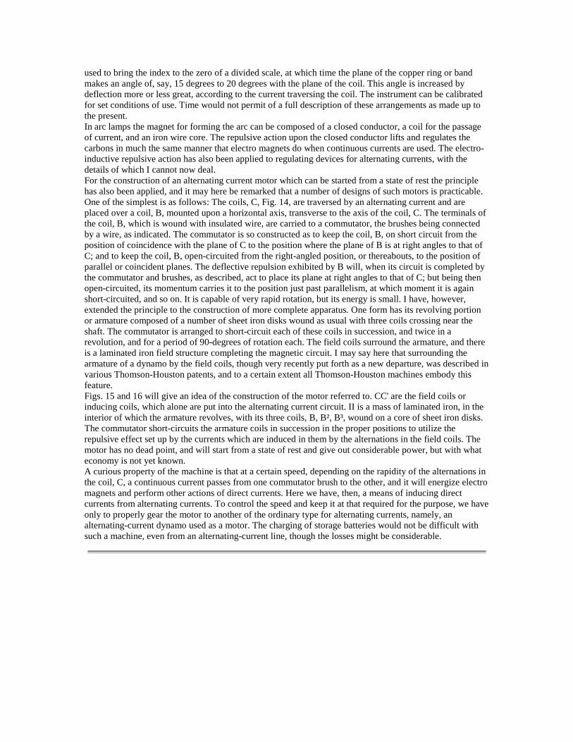
used to bring the index to the zero of a divided scale, at which time the plane of the copper ring or bandmakes an angle of, say, 15 degrees to 20 degrees with the plane of the coil. This angle is increased bydeflection more or less great, according to the current traversing the coil. The instrument can be calibratedfor set conditions of use. Time would not permit of a full description of these arrangements as made up tothe present.In arc lamps the magnet for forming the arc can be composed of a closed conductor, a coil for the passageof current, and an iron wire core. The repulsive action upon the closed conductor lifts and regulates thecarbons in much the same manner that electro magnets do when continuous currents are used. The electro-inductive repulsive action has also been applied to regulating devices for alternating currents, with thedetails of which I cannot now deal.For the construction of an alternating current motor which can be started from a state of rest the principlehas also been applied, and it may here be remarked that a number of designs of such motors is practicable.One of the simplest is as follows: The coils, C, Fig. 14, are traversed by an alternating current and areplaced over a coil, B, mounted upon a horizontal axis, transverse to the axis of the coil, C. The terminals ofthe coil, B, which is wound with insulated wire, are carried to a commutator, the brushes being connectedby a wire, as indicated. The commutator is so constructed as to keep the coil, B, on short circuit from theposition of coincidence with the plane of C to the position where the plane of B is at right angles to that ofC; and to keep the coil, B, open-circuited from the right-angled position, or thereabouts, to the position ofparallel or coincident planes. The deflective repulsion exhibited by B will, when its circuit is completed bythe commutator and brushes, as described, act to place its plane at right angles to that of C; but being thenopen-circuited, its momentum carries it to the position just past parallelism, at which moment it is againshort-circuited, and so on. It is capable of very rapid rotation, but its energy is small. I have, however,extended the principle to the construction of more complete apparatus. One form has its revolving portionor armature composed of a number of sheet iron disks wound as usual with three coils crossing near theshaft. The commutator is arranged to short-circuit each of these coils in succession, and twice in arevolution, and for a period of 90-degrees of rotation each. The field coils surround the armature, and thereis a laminated iron field structure completing the magnetic circuit. I may say here that surrounding thearmature of a dynamo by the field coils, though very recently put forth as a new departure, was described invarious Thomson-Houston patents, and to a certain extent all Thomson-Houston machines embody thisfeature.Figs. 15 and 16 will give an idea of the construction of the motor referred to. CC' are the field coils orinducing coils, which alone are put into the alternating current circuit. II is a mass of laminated iron, in theinterior of which the armature revolves, with its three coils, B, B², B³, wound on a core of sheet iron disks.The commutator short-circuits the armature coils in succession in the proper positions to utilize therepulsive effect set up by the currents which are induced in them by the alternations in the field coils. Themotor has no dead point, and will start from a state of rest and give out considerable power, but with whateconomy is not yet known.A curious property of the machine is that at a certain speed, depending on the rapidity of the alternations inthe coil, C, a continuous current passes from one commutator brush to the other, and it will energize electromagnets and perform other actions of direct currents. Here we have, then, a means of inducing directcurrents from alternating currents. To control the speed and keep it at that required for the purpose, we haveonly to properly gear the motor to another of the ordinary type for alternating currents, namely, analternating-current dynamo used as a motor. The charging of storage batteries would not be difficult withsuch a machine, even from an alternating-current line, though the losses might be considerable.


![1966 Transformer Fundamentals - Lecture Series [Westinghouse Electric Corporation]](https://img.pdfslide.us/doc/110x75/5571fae94979599169937a4c/1966-transformer-fundamentals-lecture-series-westinghouse-electric-corporation.jpg)