Embed Size (px)
Citation preview

R Y T E C
Powerhouse XL®
Owner’s Manual
P.O. Box 403, One Cedar Parkway, Jackson, WI 53037 Phone 262-677-9046 Fax 262-677-2058
Rytec website: www.rytecdoors.com, Rytec On-line store: www.rytecparts.com Rytec E-mail: [email protected], Parts E-mail: [email protected]
[Revision: AA (2017-05-09), R1600613-0, © Rytec Corporation 2012]

2
POWERHOUSE XL® LIMITED WARRANTY
Rytec Corporation (“Seller”), an Illinois corporation with its principal place of business at One Cedar
Parkway, PO Box 403, Jackson, WI 53037, warrants to the original registered end-user commercial
purchaser (“Buyer”) that the Powerhouse XL (“Product”) sold to the Buyer will be free of defects in
materials and workmanship (ordinary wear and tear excepted) for the time periods set forth below:
• Mechanical components for a period of Two (2) Years from the date of shipment of the Product
from the Seller’s plant (“Shipment”).
• Electrical components for a period of Two (2) Years from Shipment.
• Standard door panel, including SBR, lifetime limited warranty limited only to SBR panel
material.
• Optional door panel, including EPDM, for a period of Two (2) Years from Shipment.
• Panel wind locks, vertical panel seams/stripes, bottom edge rubber, loop seal, wireless
mobile unit battery, are considered wear items and are not covered under this Limited Warranty.
• Aftermarket parts, accessories and assemblies for a period of ninety (90) days from the date
of Shipment.
Remedies. Seller’s obligation under this Limited Warranty is limited to repairing or replacing, at Seller’s
option, any part which is determined by Seller to be defective during the applicable warranty period.
Such repair or replacement shall be the Seller’s sole obligation and the Buyer’s exclusive remedy under
this Limited Warranty.
Labor. Except in the case of aftermarket parts, accessories and assemblies, labor is warranted for one
year. This means that Seller will provide warranty service without charge for labor in the first year of
the warranty period. Thereafter, a charge will apply in to any repair or replacement under this Limited
Warranty. In the case of aftermarket parts, accessories and assemblies, Seller will provide replacement
parts only.
Claims. Claims under this Limited Warranty must be made (i) within 30 (thirty) days after discovery
and (ii) prior to expiration of the applicable warranty period. Claims shall be made in writing delivered
to the Seller at the address provided in the first paragraph of this warranty. Buyer must allow Seller and
Dealer, or their agents, a reasonable opportunity to inspect any Product claimed to be defective and
shall, at Seller’s option, either (x) grant Seller and Dealer or their agents access to Buyer’s premises for
the purpose of repairing or replacing the Product or (y) return of the Product to the Seller, f.o.b. Seller’s
factory.
Original Buyer. This Limited Warranty is made to the original Buyer of the Product and is not assignable
or transferable. This Limited Warranty shall not be altered or amended except in a written instrument
signed by Buyer and Seller.
Not Warranted. Seller does not warrant against and is not responsible for, and no implied warranty shall
be deemed to cover, damages that result directly or indirectly from: (i) the unauthorized modification or
repair of the Product, (ii) damage due to environmental conditions such as ice and frost on the Product,
(iii) damage due to misuse, neglect, accident, failure to provide necessary maintenance, or normal wear
and tear of the Product, (iv) failure to follow Seller’s instructions for installation, operation or maintenance
of the Product, (v) use of the Product in a manner that is inconsistent with Seller’s guidelines or local
building codes, (vi) movement, settling, distortion, or collapse of the ground, or of improvements to
which the Products are affixed, (vii) fire, flood, earthquake, elements of nature or acts of God, riots,
civil disorder, war, or any other cause beyond the reasonable control of Seller, (viii) improper handling,
storage, abuse, or neglect of the Product by Buyer or by any third party.

DISCLAIMERS. THIS WARRANTY IS EXCLUSIVE AND IN LIEU OF ALL OTHER REPRESENTATIONS
AND WARRANTIES, EXPRESS OR IMPLIED, AND THE SELLER EXPRESSLY DISCLAIMS AND
EXCLUDES ANY IMPLIED WARRANTIES OF MERCHANTABILITY OR FITNESS FOR PURPOSE.
SELLER SHALL NOT BE SUBJECT TO ANY OTHER OBLIGATIONS OR LIABILITIES, WHETHER
ARISING OUT OF BREACH OF CONTRACT, WARRANTY, TORT (INCLUDING NEGLIGENCE AND
STRICT LIABILITY) OR OTHER THEORIES OF LAW, WITH RESPECT TO THE PRODUCTS SOLD
OR SERVICES RENDERED BY THE SELLER, OR ANY UNDERTAKINGS, ACTS, OR OMISSIONS
RELATING THERETO.
LIMITATION OF LIABILITY. IN NO EVENT WILL SELLER BE RESPONSIBLE FOR, OR LIABLE TO
ANYONE FOR, SPECIAL, INDIRECT, COLLATERAL, PUNITIVE, INCIDENTAL, OR CONSEQUENTIAL
DAMAGES, EVEN IF SELLER HAS BEEN ADVISED OF THE POSSIBILITY OF SUCH DAMAGES.
Such excluded damages include, but are not limited to, personal injury, damage to property, loss of
goodwill, loss of profits, loss of use, cost of cover with any substitute product, interruption of business, or
other similar indirect financial loss.
Product Descriptions. Any description of the Products, whether in writing or made orally by the
Seller or the Seller’s agents, including specifications, samples, models, bulletins, drawings, diagrams,
engineering or similar materials used in connection with the Buyer’s order, are for the sole purpose of
identifying the Product and shall not be construed as an express warranty. Any suggestions by the Seller
or the Seller’s agents regarding the use, application, or suitability of the Product shall not be construed
as an express warranty unless confirmed to be such in writing by the Seller.
Limited Warranty Void. This Limited Warranty shall be void in its entirety if:
a) The Product is modified in a manner not approved in writing by Seller; or
b) Buyer fails to maintain the Product in accordance with instructions contained in the Owner’s
Manual for the Product.
© Rytec Corporation 3.12.2013

4

TABLE OF CONTENTS PAGE
INTRODUCTION. . . . . . . . . . . . . . . . . . . . . . . . . . . . . . . . . . . . . . . . . . . . .1
HOW TO USE MANUAL . . . . . . . . . . . . . . . . . . . . . . . . . . . . . . . . . . . . . . . . . . . . . . 1
DOOR SERIAL NUMBER . . . . . . . . . . . . . . . . . . . . . . . . . . . . . . . . . . . . . . . . . . . . . 1
GENERAL ARRANGEMENT OF DOOR COMPONENTS . . . . . . . . . . . . . . . . . . . . 2
SAFETY . . . . . . . . . . . . . . . . . . . . . . . . . . . . . . . . . . . . . . . . . . . . . . . . . . .2
MECHANICAL . . . . . . . . . . . . . . . . . . . . . . . . . . . . . . . . . . . . . . . . . . . . . . . . . . . . . . 2
ELECTRICAL . . . . . . . . . . . . . . . . . . . . . . . . . . . . . . . . . . . . . . . . . . . . . . . . . . . . . . 2
OPERATION . . . . . . . . . . . . . . . . . . . . . . . . . . . . . . . . . . . . . . . . . . . . . . . .3
CONTROL PANEL. . . . . . . . . . . . . . . . . . . . . . . . . . . . . . . . . . . . . . . . . . . . . . . . . . . 3
PHOTO EYES . . . . . . . . . . . . . . . . . . . . . . . . . . . . . . . . . . . . . . . . . . . . . . . . . . . . . . 3
BOTTOM BAR ASSEMBLY. . . . . . . . . . . . . . . . . . . . . . . . . . . . . . . . . . . . . . . . . . . . 3
Breakaway Capability . . . . . . . . . . . . . . . . . . . . . . . . . . . . . . . . . . . . . . . . . . . 3
IMPACT . . . . . . . . . . . . . . . . . . . . . . . . . . . . . . . . . . . . . . . . . . . . . . . . . . 3
RESET BOTTOM BAR ASSEMBLY . . . . . . . . . . . . . . . . . . . . . . . . . . . . . 3
Reversing Edge . . . . . . . . . . . . . . . . . . . . . . . . . . . . . . . . . . . . . . . . . . . . . . . . 4
POWER DRIVE SYSTEM . . . . . . . . . . . . . . . . . . . . . . . . . . . . . . . . . . . . . . . . . . . . . 4
MOVE THE DOOR MANUALLY . . . . . . . . . . . . . . . . . . . . . . . . . . . . . . . . . . . . . . . . 4
LIGHT CURTAIN . . . . . . . . . . . . . . . . . . . . . . . . . . . . . . . . . . . . . . . . . . . . . . . . . . . . 5
Operation . . . . . . . . . . . . . . . . . . . . . . . . . . . . . . . . . . . . . . . . . . . . . . . . . . . . . 5
PLANNED MAINTENANCE . . . . . . . . . . . . . . . . . . . . . . . . . . . . . . . . . . . .5
RECOMMENDED SCHEDULE . . . . . . . . . . . . . . . . . . . . . . . . . . . . . . . . . . . . . . . . . 5
DAILY INSPECTION . . . . . . . . . . . . . . . . . . . . . . . . . . . . . . . . . . . . . . . . . . . . . . . . . 5
Visual Damage Inspection . . . . . . . . . . . . . . . . . . . . . . . . . . . . . . . . . . . . . . . 5
Check Door Operation . . . . . . . . . . . . . . . . . . . . . . . . . . . . . . . . . . . . . . . . . . 5
LED (Light Emitting Diode) . . . . . . . . . . . . . . . . . . . . . . . . . . . . . . . . . . . . . . . 5
Photo Eye Inspection . . . . . . . . . . . . . . . . . . . . . . . . . . . . . . . . . . . . . . . . . . . 6
TESTING PHOTO EYES. . . . . . . . . . . . . . . . . . . . . . . . . . . . . . . . . . . . . . 6
Reversing Edge Inspection . . . . . . . . . . . . . . . . . . . . . . . . . . . . . . . . . . . . . . 6
WIRELESS REVERSING EDGE INSTALLATION . . . . . . . . . . . . . . . . . . . . . . . . . . 7
Manual Programming . . . . . . . . . . . . . . . . . . . . . . . . . . . . . . . . . . . . . . . . . . . 7
Total Reset . . . . . . . . . . . . . . . . . . . . . . . . . . . . . . . . . . . . . . . . . . . . . . . . . . . . 8

6
QUARTERLY INSPECTION . . . . . . . . . . . . . . . . . . . . . . . . . . . . . . . . . . . . . . . . . . . 8
Hardware Inspection . . . . . . . . . . . . . . . . . . . . . . . . . . . . . . . . . . . . . . . . . . . . 8
HEAD ASSEMBLY . . . . . . . . . . . . . . . . . . . . . . . . . . . . . . . . . . . . . . . . . . 8
REAR SPREADER . . . . . . . . . . . . . . . . . . . . . . . . . . . . . . . . . . . . . . . . . . 8
Wall Anchor Inspection. . . . . . . . . . . . . . . . . . . . . . . . . . . . . . . . . . . . . . . . . . 9
Welds (If Applicable) . . . . . . . . . . . . . . . . . . . . . . . . . . . . . . . . . . . . . . . . . . . . 9
Fabric Inspection . . . . . . . . . . . . . . . . . . . . . . . . . . . . . . . . . . . . . . . . . . . . . . 10
Bottom Bar Inspection . . . . . . . . . . . . . . . . . . . . . . . . . . . . . . . . . . . . . . . . . 10
Brush Seal Inspection. . . . . . . . . . . . . . . . . . . . . . . . . . . . . . . . . . . . . . . . . . 11
Door Limit Inspection . . . . . . . . . . . . . . . . . . . . . . . . . . . . . . . . . . . . . . . . . . 11
CLOSE LIMIT . . . . . . . . . . . . . . . . . . . . . . . . . . . . . . . . . . . . . . . . . . . . . 11
OPEN LIMIT . . . . . . . . . . . . . . . . . . . . . . . . . . . . . . . . . . . . . . . . . . . . . . 11
Motor Brake Inspection. . . . . . . . . . . . . . . . . . . . . . . . . . . . . . . . . . . . . . . . . 12
MANUAL DOOR OPERATION . . . . . . . . . . . . . . . . . . . . . . . . . . . . . . . . 12
Activator and Control Panel Inspection . . . . . . . . . . . . . . . . . . . . . . . . . . . 12
Electrical Connection Inspection . . . . . . . . . . . . . . . . . . . . . . . . . . . . . . . . . 12
Lubrication . . . . . . . . . . . . . . . . . . . . . . . . . . . . . . . . . . . . . . . . . . . . . . . . . . . 12
ADJUSTMENT . . . . . . . . . . . . . . . . . . . . . . . . . . . . . . . . . . . . . . . . . . . . .13
DOOR LIMITS . . . . . . . . . . . . . . . . . . . . . . . . . . . . . . . . . . . . . . . . . . . . . . . . . . . . . 13
Setting Door Limits . . . . . . . . . . . . . . . . . . . . . . . . . . . . . . . . . . . . . . . . . . . . 13
Limit Switch Designations . . . . . . . . . . . . . . . . . . . . . . . . . . . . . . . . . . . . . . 14
CHAIN TENSION. . . . . . . . . . . . . . . . . . . . . . . . . . . . . . . . . . . . . . . . . . . . . . . . . . . 14
PROXIMITY SENSORS . . . . . . . . . . . . . . . . . . . . . . . . . . . . . . . . . . . . . . . . . . . . . . 15
REPLACEMENT PROCEDURES. . . . . . . . . . . . . . . . . . . . . . . . . . . . . . .16
BRUSH SEAL(S) . . . . . . . . . . . . . . . . . . . . . . . . . . . . . . . . . . . . . . . . . . . . . . . . . . . 16
MISCELLANEOUS . . . . . . . . . . . . . . . . . . . . . . . . . . . . . . . . . . . . . . . . . .16
MANUAL DOOR PANEL MOVEMENT . . . . . . . . . . . . . . . . . . . . . . . . . . . . . . . . . . 16
WIRE SCHEMATIC . . . . . . . . . . . . . . . . . . . . . . . . . . . . . . . . . . . . . . . . .18
GENERAL . . . . . . . . . . . . . . . . . . . . . . . . . . . . . . . . . . . . . . . . . . . . . . . . . . . . . . . . 18
BOTTOM BAR. . . . . . . . . . . . . . . . . . . . . . . . . . . . . . . . . . . . . . . . . . . . . . . . . . . . . 20
DIRECT DRIVE MOTOR . . . . . . . . . . . . . . . . . . . . . . . . . . . . . . . . . . . . . . . . . . . . . 20
CHAIN DRIVE MOTOR . . . . . . . . . . . . . . . . . . . . . . . . . . . . . . . . . . . . . . . . . . . . . . 21

PARTS LIST . . . . . . . . . . . . . . . . . . . . . . . . . . . . . . . . . . . . . . . . . . . . . . .23
PARTS ORDERING INFORMATION . . . . . . . . . . . . . . . . . . . . . . . . . . . . . . . . . . . . 23
How to Order Parts . . . . . . . . . . . . . . . . . . . . . . . . . . . . . . . . . . . . . . . . . . . . 23
Substitute Parts . . . . . . . . . . . . . . . . . . . . . . . . . . . . . . . . . . . . . . . . . . . . . . . 23
Return of Parts. . . . . . . . . . . . . . . . . . . . . . . . . . . . . . . . . . . . . . . . . . . . . . . . 23
REAR SPREADER WITH IDLER . . . . . . . . . . . . . . . . . . . . . . . . . . . . . . . . . . . . . . 24
HEAD ASSEMBLY–DIRECT DRIVE . . . . . . . . . . . . . . . . . . . . . . . . . . . . . . . . . . . . 26
HEAD ASSEMBLY–CHAIN DRIVE . . . . . . . . . . . . . . . . . . . . . . . . . . . . . . . . . . . . . 28
SIDE COLUMN ASSEMBLY . . . . . . . . . . . . . . . . . . . . . . . . . . . . . . . . . . . . . . . . . . 30
HOOD ASSEMBLY . . . . . . . . . . . . . . . . . . . . . . . . . . . . . . . . . . . . . . . . . . . . . . . . . 32
DRUM AND DOOR PANEL ASSEMBLY . . . . . . . . . . . . . . . . . . . . . . . . . . . . . . . . 34
BOTTOM BAR ASSEMBLY. . . . . . . . . . . . . . . . . . . . . . . . . . . . . . . . . . . . . . . . . . . 36
BEARING PLATE ASSEMBLY . . . . . . . . . . . . . . . . . . . . . . . . . . . . . . . . . . . . . . . . 38
MOTOR GEARBOX DIRECT DRIVE ASSEMBLY . . . . . . . . . . . . . . . . . . . . . . . . . 40
MOTOR GEARBOX CHAIN DRIVE ASSEMBLY . . . . . . . . . . . . . . . . . . . . . . . . . . 42

8

1
INTRODUCTION—HOW TO USE MANUAL
INTRODUCTION
The information contained in this manual will allow
you to maintain your Rytec Powerhouse XL® Door
in a manner that will ensure maximum life and
trouble-free operation.
Any unauthorized changes to these procedures, or
failure to follow the steps as outlined, will
automatically void the warranty. Any changes to the
working parts, assemblies, or specifications as
written, that are not authorized by Rytec
Corporation, will also cancel the warranty. The
responsibility for the successful operation and
performance of this door lies with the owner.
DO NOT INSTALL, OPERATE, OR PERFORM
MAIN TENANCE ON THIS DOOR UNTIL YOU
READ AND UNDERSTAND ALL THE
INSTRUCTIONS IN THIS MANUAL.
If you have any questions, contact your Rytec
representative or call the Rytec Technical Support
Department at 1-800-628-1909. Always refer to the
serial number of the door when calling your
representative or technical support. The location of
the serial number is on the left side of the head
assembly.
The wiring connections and schematics in this
manual are for general information purposes only.
The actual schematic for your custom installation is
located in the crate when the door is delivered.
HOW TO USE MANUAL
Throughout this manual, the following key words
are used to alert the reader to potentially hazardous
situations, or situations where additional information
to successfully perform the procedure is presented:
WARNING is used to indicate the potential
for personal injury, if the procedure is not
performed as described.
CAUTION is used to indicate the potential for damage to the product or property damage, if the procedure is not followed as described.
IMPORTANT: IMPORTANT is used to relay
information that is CRITICAL
to the successful completion of
the procedure.
NOTE: NOTE is used to provide additional information to aid in the performance of the procedure or operation of the door, but not necessarily safety related.
DOOR SERIAL NUMBER(S)
To obtain your DOOR SERIAL NUMBER, there are three (3) universal locations that this information can be attained. These are on the left side column assembly (at approximately eye level), on the head assembly, and on the right side column assembly.
When installing multiple doors of the same model, verify & match the serial numbers of all the components for each door (i.e. control panel, side columns, drive assembly, etc.). Mark any items not previously marked.
NOTE: The following illustration shows the front side of the door. Left and right sides are determined when viewing the front side of the door.
Figure 1
A5800073 Side Columns
Motor-Gear Drive
Door Panel Assembly Serial Number
Location

2
SAFETY—GENERAL ARRANGEMENT OF DOOR COMPONENTS
GENERAL ARRANGEMENT OF
DOOR COMPONENTS
Figure 2 shows the location of the major components of
the door and the general placement of the associated
sub-assemblies for a typical installation.
NOTE: These illustrations are for informational
purposes only. They should not be relied upon
solely during the installation of your door and its
sub-assemblies.
IMPORTANT: The surface of the wall on which
the door is to be installed must be free of any
obstructions. Also, any existing door framing
on the wall should be removed or the side
columns will require shimming before installing.
NOTE: Figure 2 shows the front of the door. Left and
right are determined when viewing the front of
the door.
SAFETY
MECHANICAL
• This is a breakaway, partially self-repairable door.
Upon impact, the door panel will pop out of the side
column guide(s) and will need to be operated to the
fully open position to allow the door to reset. The
door panel has an edge that may bind in the side
column if not completely broken away. Therefore, the
motor may stall while trying to operate the door to the
fully open position. If the operator is unable to get the
door to the fully open position using the control panel,
the side column cover(s) may have to be opened to
allow the panel to travel. (See Figure 3)
Head Assembly without Hood
Edge of Door Panel
Motor/Gearbox with Optional Heaters
Left Side Column
A5800074
Right Side Column
SBR Rubber Door Panel w/Bottom Bar
A5800062
Open Side Column
Figure 3
Figure 2
ELECTRICAL
• When working with electrical or electronic controls
make sure that the power source has been locked
out and tagged according to OSHA regulations and
approved local electrical codes.
• Qualified electricians must do all electrical wiring.
Wiring must meet all local, state, and federal codes.
• Please check the documentation for what voltage is
specified. Confirm power supply to be as required:
208V, 230/240V, 460/480V, or 575V. Voltage and
fuses or breakers should be checked before
connecting to the main power supply.

3
OPERATION—CONTROL PANEL
OPERATION
CONTROL PANEL
The Powerhouse XL Door is equipped with the Rytec
System 4 Drive & Control, a solid-state, microprocessor-
based control system designed exclusively to operate
Rytec high-performance doors. It provides connections
for multiple activators, close-delay timers, and status
indicators. All command functions to operate the drive
and control system are software controlled. For
information on control panel operation, see the Rytec
System 4 Drive & Control Installation & Owner’s Manual.
PHOTO EYES
Your Powerhouse XL is optioned with two sets of photo
eyes, one set mounted on the front and another set
installed on the back of the door. The purpose of these
photo eyes is to hold the door open or, if the door is
closing, reverse the door to the open position if a
vehicle, person, or any object is in the path of the photo
eye beam.
The photo eye is not active when the door is closed.
After the obstruction breaking the photo eye beam is
removed:
The door will remain open if it was originally opened by
a non-automatic activator until it is closed by a non-
automatic activator.
The door will close automatically if it was originally
opened with an automatic activator.
BOTTOM BAR ASSEMBLY
The bottom bar assembly houses the wireless reversing
edge.
Breakaway Capability
IMPACT
End tabs mounted at each end of the bottom bar provide
adequate strength to keep the assembly in contact with
the side columns during normal operation. The tabs,
however, are flexible enough to allow the bottom bar to
separate from either or both of the side columns should
the bottom bar be struck by a vehicle or load passing
through the door. Open the side columns and use the
chain fall to manually open the door to the full open
height allowing for the panel to reset itself. The motor(s)
must be placed into the manual mode prior to any chain
fall movement. When the panel has been reset, place
the motor(s) back into automatic operation. (See “MOVE
THE DOOR MANUALLY” on page 4)
Figure 4
RESET BOTTOM BAR ASSEMBLY
If the bottom bar or door panel assembly has
been damaged, remove door from service.
Turn off power to the control and open both side
columns. (See Figure 5)
Figure 5
Place operator(s) into manual mode and raise the door
to the full open position with the chain fall(s).
Close both side columns and place the operator(s) back
into automatic mode.
NOTE: Check to make sure that the fabric is inside
each channel.
Check operation of door.
End Tabs
Side Column
A5800162
Angled Guide Plate
Bottom Bar
End Tabs
A5800024

4
OPERATION—POWER DRIVE SYSTEM Reversing Edge
The door is equipped with a pneumatic reversing edge
mounted at the bottom of the bottom bar assembly. If an
object is left in the path of the door panel as it closes,
the pressure-sensitive edge will sense the contact with
the object and automatically reverse the door to the
open position, thus preventing damage to the bottom
bar. (See Figure 6)
MOVE THE DOOR MANUALLY
The disconnect must be in the OFF position
and properly locked and tagged before
performing the following procedure.
DO NOT stand under the door panel when
moving the door.
End Tab
Reversing Edge
A5800075
Bottom Bar
The drive motor has red and green handles hanging
from the bottom of the motor. When the green handle
is pulled or in the lowest position, the drive motor is
engaged to run on electrical power. When the red
handle is pulled or in the lowest position, electrical
power has been disengaged and manual door
operation is required, using the chain. Also, when the
red handle is pulled, a sensor is engaged and will not
allow electrical power to the door.
Electrical power can be shut off anytime to operate the
electric motor in manual mode. Control panel limit set
tings will not be affected when switching the power off
and back on. The door will return to a normal operating
mode. (See Figure 7)
Figure 6
POWER DRIVE SYSTEM
The Powerhouse XL power drive system consists of an
electric motor/brake assembly, reduction gear assembly,
and encoder. The standard Powerhouse XL is equipped
with a variable-speed motor. The control system will
vary the door speed depending on door position. The
power drive system can be mounted on either the right
or left end of the fabric roll.
The power drive system incorporates an electric brake
used to stop the door travel when electrical power to the
door is shut off. A manual brake release is provided for
manual opening or closing of the door should there be a
power failure, or when routine maintenance needs to be
performed with the power disconnected.
An encoder, mounted on the end of the gearbox,
generates electrical signals as the door panel moves.
These signals are used by the control system to monitor
the position of the door.
Red Handle
Green Handle in Lowest Position Chain
A5800060
Figure 7

5
PLANNED MAINTENANCE—LIGHT CURTAIN LIGHT CURTAIN
Operation
Your Rytec Powerhouse XL Door is equipped with a pair
of light curtains for monitoring the door, an emitter
module, and a receiver module. The purpose of these
light curtains is to hold the door open or, if the door is
closing, reverse the direction of the door if a person or
object breaks the beam of light between the light
curtains. After the obstruction breaking the beam of light
is removed:
• If the door was originally opened by an automatic
activator, the door will close automatically.
• If the door was originally opened by a non-automatic
activator, the door will remain open until it is closed
by the non-automatic activator.
NOTE: The light curtains are not intended to be used
as a door activator and will not open the door
when it is closed.
DAILY INSPECTION
Visual Damage Inspection
Visually inspect the door to see that components have
not been damaged. Example: bent bottom bar
assembly, torn fabric panel, damage to side columns,
etc. (See Figure 8)
Head Assembly Without Hood
Motor/Gearbox With Optional Heaters
PLANNED MAINTENANCE
RECOMMENDED SCHEDULE
NOTE: The following maintenance schedule is
recommended for the Rytec Cycle-Plus
maintenance program.
Left Side Column
A5800074
Right Side Column
SBR Rubber Door Panel w/Bottom Bar
Figure 8
Head Assembly: Inspect for dents or damage that may
prevent the door from opening or closing properly.
Door Panel: Inspect panel for holes, tears, and worn
areas. If equipped with windows, inspect them for dam-
age or dirt that may impair vision — clean or replace as
required.
Side Columns: Inspect for damage that may prevent
the door from operating properly.
Bottom Bar: Inspect the bottom bar for damaged,
missing, or loose hardware. Inspect the yellow vinyl seal
along the lower edge of the bottom bar for tears and
holes. Inspect the edge itself.
Check Door Operation
Run the door through four or five complete cycles to
verify that the door is operating smoothly and efficiently,
and that binding or unusual noises do not exist. DO
NOT continue to operate the door if it is not running
properly, as this could compound the damage.
LED (Light Emitting Diode)
Inspect the lens of each LED for damage or dirt that
may prevent the lights from working properly — clean or
replace as required. (See Figure 9)
Daily Quarterly
Visual Damage Inspection Check Door Operation LED Inspection Photo Eye Inspection Reversing Edge Inspection Hardware Inspection Wall Anchor Inspection Welds (If Applicable) Fabric Inspection Bottom Bar Inspection Brush Seal Inspection Door Limit Inspection Motor Brake Inspection Activator and Control Panel
Inspection
Electrical Connection Inspection Lubrication

6
PLANNED MAINTENANCE—DAILY INSPECTION
Front LED
Receiver Module Designation
Inner LED
Alignment Light (Yellow)
A5800025
Photo Eye Inspection
Figure 9
A2500259
Figure 11
The photo eyes are provided as a safety feature. If the
photo eyes are installed correctly, any object in the path
of the photo eye beam while the door is closing will
cause the door to reverse direction and remain in the
fully open position until the obstruction is removed.
The transmitter and receiver can be identified in two
ways. The transmitter is designated SMT 3000 on the
white label or by a single green light that comes on at
the clear end of the transmitter. (See Figure 10) The
receiver is designated SMR 3215 on the white label or
by a yellow light that illuminates only when it is in proper
alignment with the transmitter. (See Figure 11)
NOTE: When the cable is connected to the photo
eye, there is only a ¹/₄-in. window to see the
green or yellow LED light.
Transmitter Module Designation
Check the front and rear photo eye assemblies for:
a. Good wire cable connections at the photo eye.
b. Secure and solid mounting bracket.
c. Photo eye installed properly in the mounting
bracket.
d. Check for green and yellow lights.
e. Cracked photo eye housing.
f. Clean photo eye lens.
1. Repair or replace items as needed.
2. After all work is complete, clean the lens of each
photo eye using window cleaner and a soft, clean
cloth.
TESTING PHOTO EYES
With the power on, the green light on the transmitter
indicates that the photo eye module is powered up.
When the yellow light on the receiver module is also lit,
the transmitter and receiver modules are properly
aligned.
Placing your hand in front of the receiver breaks the
light path and causes the yellow light to go out.
Removing your hand causes the yellow light to go
back on.
Reversing Edge Inspection
A2500258
Figure 10
Power Light (Green)
DO NOT stand under the door when per-
forming the following test. If the reversing
edge sensor is not working properly, the
door could strike the person performing
the procedure. DO NOT use the door if the
sensor is not working properly.

7
PLANNED MAINTENANCE—WIRELESS REVERSING EDGE INSTALLATION 1. Move the door to the open position by pressing the
door open button located on the control panel.
2. Press the door close button.
3. When the door is a few feet from the fully closed
position, hit the rubber reversing edge that runs
along the bottom edge of the door. Stand outside
the photo eyes to avoid activating the photo eye
circuit. (See Figure 12)
4. Check the mobile unit assembly. Make sure that it
is tight and secure. Inspect terminal block for
damage and replace any missing or damaged
hardware. (See Figure 13)
Mobile Unit
Assembly
A5800075
A5800162
Figure 12
Door Reverse Switch Housed in Rubber Edge
Figure 13
5. Inspect the rubber reversing edge. It should be in
good condition with no visible holes, cracks, or tears.
Replace the rubber reversing edge if necessary.
WIRELESS REVERSING EDGE INSTALLATION
While the door is running through the down cycle, strike
the bottom of the reversing edge. If the reversing edge
is operating properly, the door should immediately
reverse and run to the full-open position. Press the
control panel down key to close the door after the
inspection is complete.
If the reversing edge sensor is not working properly,
the control system will only allow the door to open and
the control panel will display the associated error code.
NOTE: A normal resistance measurement across
the reversing edge sensor will read
approximately 8.2 k-ohms. With the
rubber edge compressed, the resistance
will drop to about zero ohms.
The wireless reversing edge has been programmed at
Rytec Corporation. Wire the wireless reversing edge
receiver per the schematic received with your control
panel. In the event the wireless reversing edge
appears not to function, perform the total reset
procedure and manual programming steps.
Manual Programming
Press the receiver programming button for 1 sec. and
an acoustic signal will be heard. The receiver will enter
standard programming. Every time a transmitter is
programmed, the receiver will issue an acoustic signal
for 0.5 sec. After 10 sec. without programming or
pressing the first two transmitter buttons or pressing
the PROG button, the receiver will exit programming
mode, issuing two acoustic signals of 1 sec. If upon
programming a transmitter the receiver memory is full,
it will issue 7 acoustic signals of 0.5 sec. and exit
programming.

8
PLANNED MAINTENANCE—QUARTERLY INSPECTION
Total Reset
In programming mode, the programming button is
held down and a reset jumper is bridged for 3 sec.
The receiver will issue 10 short acoustic warning
signals followed by others at a faster pace to
indicate that the operation has been successful.
The receiver is now in programming mode. (See
Figure 14)
Figure 14
After 10 sec. without programming or quickly
pressing the programming button, the receiver will
exit programming mode, issuing two acoustic
signals of 1 sec.
QUARTERLY INSPECTION
The disconnect must be in the OFF
position and properly locked and tagged
before performing the following procedure.
Hardware Inspection
Make sure all nuts, bolts, set screws, snap rings,
and anchors are tight throughout the door.
Example: motor mounting bolts, wall mounting
hardware, pillow block bearing hardware, floor
anchors, set screws, etc. (See Figure 15 and 16)
HEAD ASSEMBLY
Figure 15
REAR SPREADER
Figure 16
A5800183
Cap Screws and Lock Washers
Bearings
Nut(s)
Anchors
Bearings
A5800067
Cap Screws Washers
Rear Spreader Assembly
A5800007

9
PLANNED MAINTENANCE—QUARTERLY INSPECTION
Wall Anchor Inspection
The disconnect must be in the OFF position
and properly locked and tagged before
performing the following procedure.
1. Turn off power to the door.
2. Gain access to wall and rear spreader anchors.
3. Inspect for loose or worn anchor(s). (See Figure
17 and 18)
Figure 17
Figure 18
4. Tighten, repair, or replace anchor(s) as needed.
NOTE: Remove door from service if any
repairs are needed. All repairs must be
done in accordance with municipal
building codes.
5. Restore power to the door and return to service.
Welds (If Applicable)
The disconnect must be in the OFF position
and properly locked and tagged before
performing the following procedure.
1. Turn off power to the door.
2. Inspect broken or cracked welds on side column
assemblies. Rework the weld as needed. (See
Figure 19)
NOTE: The door assembly, walls, and building
structure MUST BE properly grounded.
NOTE: Right side column shown with multiple anchors
LED Light
Wall Anchors
A5800006
Anchor
Rear Spreader Assembly
A5800008

10
PLANNED MAINTENANCE—QUARTERLY INSPECTION
Figure 19
Fabric Inspection
1. Turn off power to the door.
The disconnect must be in the OFF position
and properly locked and tagged before
performing the following procedure.
2. Check the fabric for holes, tears, and worn
areas. Repair or replace as required.
3. If your door panel is equipped with windows,
inspect them for damage or dirt that may impair
vision. Clean or replace as required.
IMPORTANT: Use any good brand of window
cleaner to clean the windows.
DO NOT use abrasive cleaners
or petroleum-based solvents.
4. Ensure the panel is securely fastened to the
bottom bar assembly. Tighten or replace loose
or damaged mounting hardware as required.
(See Figure 20.)
Figure 20
Bottom Bar Inspection
1. Move the bottom bar of the door to a convenient
height for inspection and turn off power. Remove
hardware and open side column doors.
The disconnect must be in the OFF position
and properly locked and tagged before
performing the following procedure.
2. Inspect hardware used to secure the breakaway
assembly to the bottom bar. Tighten or replace
hardware as required.
3. Check all hardware. Tighten or replace loose or
damaged mounting hardware as required.
4. Check for bent or damaged bottom bar.
5. Check the hardware on the mobile unit and
vibration sensor. Both assemblies should be
mounted solid and sturdy, especially the
vibration sensor. Any excess movement will give
a false reading and send an error code to the
control panel.
6. Inspect the reversing edge to ensure that it is
tightly secured to the bottom bar.
7. Inspect sealed reversing edge for tears or
abrasions. An improper seal will make the door
malfunction and not change direction upon
impact. (See Figure 21)
NOTE: The door assembly, walls, and building
structure MUST BE properly grounded.
A5800052
A 4-in. Weld is Placed Every 16-in.
A 4-in. Weld is Placed Every 16-in.
SBR Rubber Door Panel w/ Bottom Bar
A5800002

11
PLANNED MAINTENANCE—QUARTERLY INSPECTION
Figure 21
Brush Seal Inspection
NOTE: The brush seal is mounted on the rear
spreader.
1. Inspect brush seal for wear and tear. Replace as
necessary. (See Figure 22)
Figure 22
Door Limit Inspection
CLOSE LIMIT
With the door in the closed position, check the
reversing edge. It should be in the position shown in
Figure 23.
Damage to the rubber reversing edge or
other bottom bar parts can occur if the door
seal is allowed to seal too tightly against the
floor. (See Figure 23)
Figure 23
OPEN LIMIT
The open-limit position should be adjusted so that
the door travel allows the bottom bar assembly to
stop even with the lintel. (See Figure 24)
Figure 24
A5800121
Mobile Unit
Reversing edge
Rear Spreader
Brush Seal
A5800022
Open Side Column
Reversing edge
A5800082
End Bracket
Bottom Bar
Lintel
A5800089

12
PLANNED MAINTENANCE—QUARTERLY INSPECTION
Motor Brake Inspection
The power drive brake assembly is designed to stop
the door panel travel at the locations indicated in the
limit switch inspection section. If the limit switches
are set properly and the door drifts past the set
limits, the brake should be replaced.
MANUAL DOOR OPERATION
With door power turned off, pull the red handle to the
motor/gearbox to engage chain drive operation.
Manually move the door panel up and down making
sure the operation is smooth and friction free. Pull
the green handle to re-engage electrical operation.
Restore power to the system and perform operations
check.
Activator and Control Panel Inspection
1. Inspect all warning and safety labels. All labels
should be intact, clean, and clearly legible.
Replace any label when necessary.
2. Operate the door five or six complete open and
close cycles with each activator installed with
the door. Make any necessary adjustments or
repairs. Refer to the associated manual supplied
with each activator installed with your door.
Typical activators may include a floor loop, pull
cord, push button, mag card, motion detector,
radio control, or photo eye. The door open cycle
is controlled by the activator. The door close
cycle can be controlled by an activator or by a
timer internal to the control panel.
Electrical Connection Inspection
The disconnect must be in the OFF position
and properly locked and tagged before
performing the following procedure.
1. Turn off power to the door.
2. Inspect all electrical connections to the power
drive system. All connections must be secure
and tight.
3. Inspect the electrical connections in the junction
box located near the head assembly. All
connections must be secure and tight.
4. For the proper door operator electrical
connection, see the wire diagram or schematic
that came with the door.
5. Clean or replace weak connection point.
Lubrication
The disconnect must be in the OFF position
and properly locked and tagged before
performing the following procedure.
The Rytec Powerhouse XL door is maintenance free
when it comes to lubrication. Although a visual
inspection should be performed to analyze any
mechanical problems that have gone unnoticed.
Operate the door and observe for any unusual
noises or erratic operation. If a sealed bearing has
gone bad, it will have a tendency to make a grinding
or growl noise. This is a good indication that the
bearing needs to be replaced.
Pillow Block: The idler is supported by a pillow
block bearing located at each end. The bearings are
normal duty, self-aligning, and sealed pre-lubricated
steel cage cast iron housings. A general purpose
grease should be used. (See Figure 25)
NOTE: “F” head assembly shown.
Figure 25
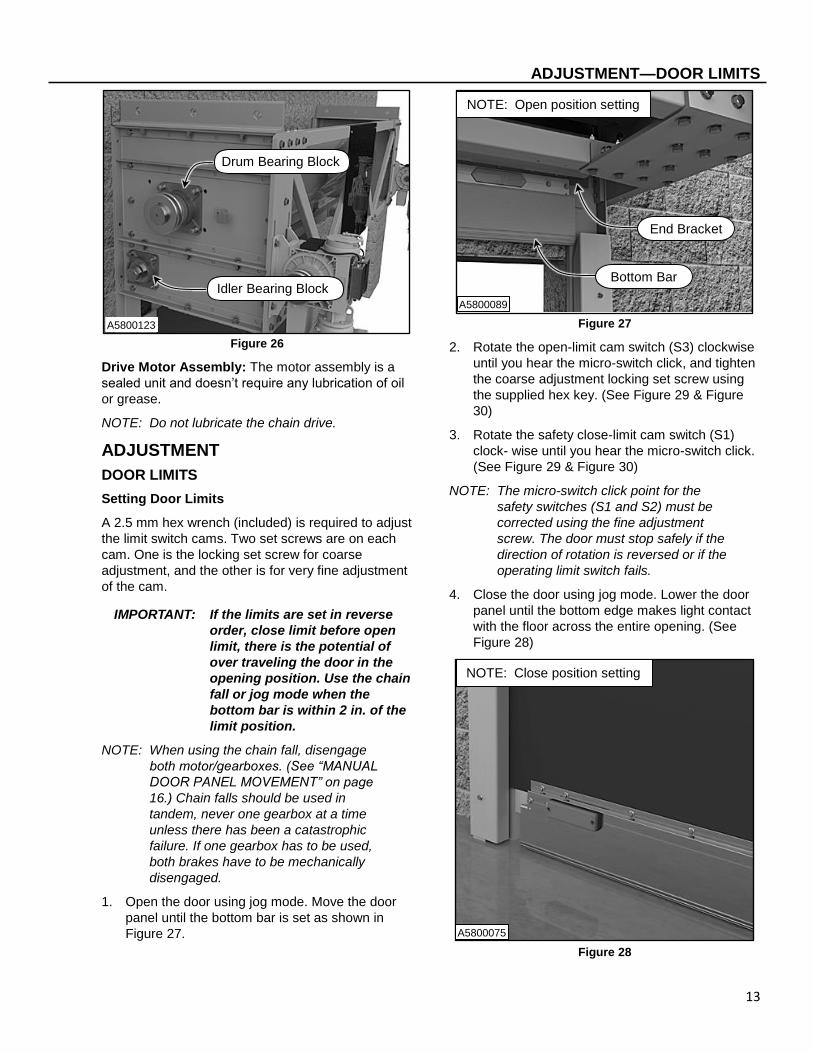
Bearing Block: The drum and idler are supported
by a bearing block located at each end. The
bearings are normal duty, self-aligning, and sealed
pre-lubricated steel cage cast iron housings. They
do not require any lubrication. (See Figure 26)
Zerk Fitting
Pillow Block Bearing
A5800122
13
ADJUSTMENT—DOOR LIMITS
Figure 26
Drive Motor Assembly: The motor assembly is a
sealed unit and doesn’t require any lubrication of oil
or grease.
NOTE: Do not lubricate the chain drive.
ADJUSTMENT
DOOR LIMITS
Setting Door Limits
A 2.5 mm hex wrench (included) is required to adjust
the limit switch cams. Two set screws are on each
cam. One is the locking set screw for coarse
adjustment, and the other is for very fine adjustment
of the cam.
IMPORTANT: If the limits are set in reverse
order, close limit before open
limit, there is the potential of
over traveling the door in the
opening position. Use the chain
fall or jog mode when the
bottom bar is within 2 in. of the
limit position.
NOTE: When using the chain fall, disengage
both motor/gearboxes. (See “MANUAL
DOOR PANEL MOVEMENT” on page
16.) Chain falls should be used in
tandem, never one gearbox at a time
unless there has been a catastrophic
failure. If one gearbox has to be used,
both brakes have to be mechanically
disengaged.
1. Open the door using jog mode. Move the door
panel until the bottom bar is set as shown in
Figure 27.
Figure 27
2. Rotate the open-limit cam switch (S3) clockwise
until you hear the micro-switch click, and tighten
the coarse adjustment locking set screw using
the supplied hex key. (See Figure 29 & Figure
30)
3. Rotate the safety close-limit cam switch (S1)
clock wise until you hear the micro-switch click.
(See Figure 29 & Figure 30)
NOTE: The micro-switch click point for the
safety switches (S1 and S2) must be
corrected using the fine adjustment
screw. The door must stop safely if the
direction of rotation is reversed or if the
operating limit switch fails.
4. Close the door using jog mode. Lower the door
panel until the bottom edge makes light contact
with the floor across the entire opening. (See
Figure 28)
Figure 28
Idler Bearing Block
Drum Bearing Block
A5800123
A5800089
Bottom Bar
End Bracket
NOTE: Open position setting
NOTE: Close position setting
A5800075

14
ADJUSTMENT—CHAIN TENSION
5. Rotate the close-limit cam switch (S4) clockwise until you hear the micro-switch click, and tighten the coarse adjustment locking set screw using the supplied hex key. (See Figure 29 & Figure 30)
6. Rotate the safety close-limit cam switch (S2) clock- wise until you hear the micro-switch click. (See Figure 29 & Figure 30)
Limit Switch Designations
S1 — Safety Open
IMPORTANT: Each limit wheel, except S1 and S2, has a coarse adjustment screw. S1 is fine adjustment only. This should be very close to the open limit; less than 1 in. This is used as a backup; set only if open limit fails.
S2 — Safety Close
IMPORTANT: Each limit wheel, except S1 and S2, has a course adjustment screw. S2 is fine adjustment only. This should be very close to the close limit; less than 1 in. This is used as a backup; set only if close limit fails.
S3 — Open
S4 — Close
S5 — Spare (Unused at this time)
S6 — Photo Eye Bypass
Figure 29
Figure 30
CHAIN TENSION
The chain tension is set at the factory. If the chain starts skipping or if the door is not operating smoothly and efficiently, an adjustment is required.
The disconnect must be in the OFF position and properly locked and tagged before performing the following procedure.
1. Turn off power to the door.
2. Gain access to the chain drive.
3. Verify the amount of tension in the drive chain. A correctly-tensioned chain will deflect no more than two in. (See Figure 31)
Micro-Switch
Hex Key
Coarse Adjustment
Fine Adjustment
S5 S4
S1 S2
S3 S6
A5800080
Hex Key
S5
S4
S1
S2
S3
S6
A5800087

15
ADJUSTMENT— PROXIMITY SENSORS
Figure 31
4. Loosen the four pieces of hardware that mount
the motor/gearbox to the head assembly. (See
Figure 32)
Figure 32
5. Adjust the motor/gearbox assembly. Moving the
assembly down will increase the tension and
decrease deflection. The exact opposite will
result from moving the assembly up.
6. Tighten hardware when proper chain deflection
has been attained.
7. Perform operations check on the door. Adjust if
needed.
8. Return door back to service.
PROXIMITY SENSORS
The proximity sensors are part of an emergency stop
circuit. If a chain breaks, the proximity sensor opens
the emergency stop circuit and the controller stops
the door. There is one on each side if there are dual
motors, or one for a single. These proximity sensors
(#1600435-0) may come loose over time and need
to be readjusted.
1. Loosen the appropriate adjustment screws for a
vertical (up or down) or horizontal (in or out)
adjustment.
2. Center the proximity sensor on the chain. This
would be a vertical adjustment.
3. Adjust the proximity sensor to an operating
distance 0.62–0.78 in. (16–20 mm). This would
be a horizontal adjustment. (See Figure 33)
Figure 33
2-in. Deflection (Maximum)
A5800091
A5800094
Cap Screw, Lock Washer, Washer
and Nut
A5800182
Adjustment Screws
Proximity Sensor
Horizontal Adjustment
Vertical Adjustment

16
REPLACEMENT PROCEDURES—BRUSH SEAL(S)
REPLACEMENT PROCEDURES
BRUSH SEAL(S)
The disconnect must be in the OFF position
and properly locked and tagged before
performing the following procedure.
1. Raise the door panel and leave in the open
position. Turn off power to the door.
2. Gain access to the rear spreader by lifting the
bottom bar with door panel and moving it to the
other side of the idler roller. (See Figure 34)
Figure 34
3. Remove serrated flange lock nuts and rear
spreader track. (See Figure 35)
Figure 35
4. Remove the old brush seal and replace with a
new one.
5. Install rear spreader track and serrated flange
lock nuts.
6. Reposition the bottom bar with door panel to its
original routing over the idler roller.
7. Restore power to the door.
NOTE: The door panel will reset itself after the
power has been restored.
8. Perform operations check. Adjust door limits as
needed.
MISCELLANEOUS
MANUAL DOOR PANEL MOVEMENT
The drive motor has red and green handles hanging
from the bottom of the motor. When the green
handle is pulled or in the lowest position, the drive
motor is engaged to run on electrical power. When
the red handle is pulled or in the lowest position,
electrical power has been disengaged and manual
door operation is required, using the chain. Also,
when the red handle is pulled, a sensor is engaged
and will not allow electrical power to the door.
Electrical power can be shut off anytime to operate
the door in manual mode. Control panel limit settings
will not be affected when switching the power off and
back on. The door will return to a normal operating
mode. (See Figure 36)
Rear Spreader Track with Brush Seal
Serrated Flange Lock Nut
A5800081
A5800071
Idler Roller
Bottom Bar
Door Panel
17
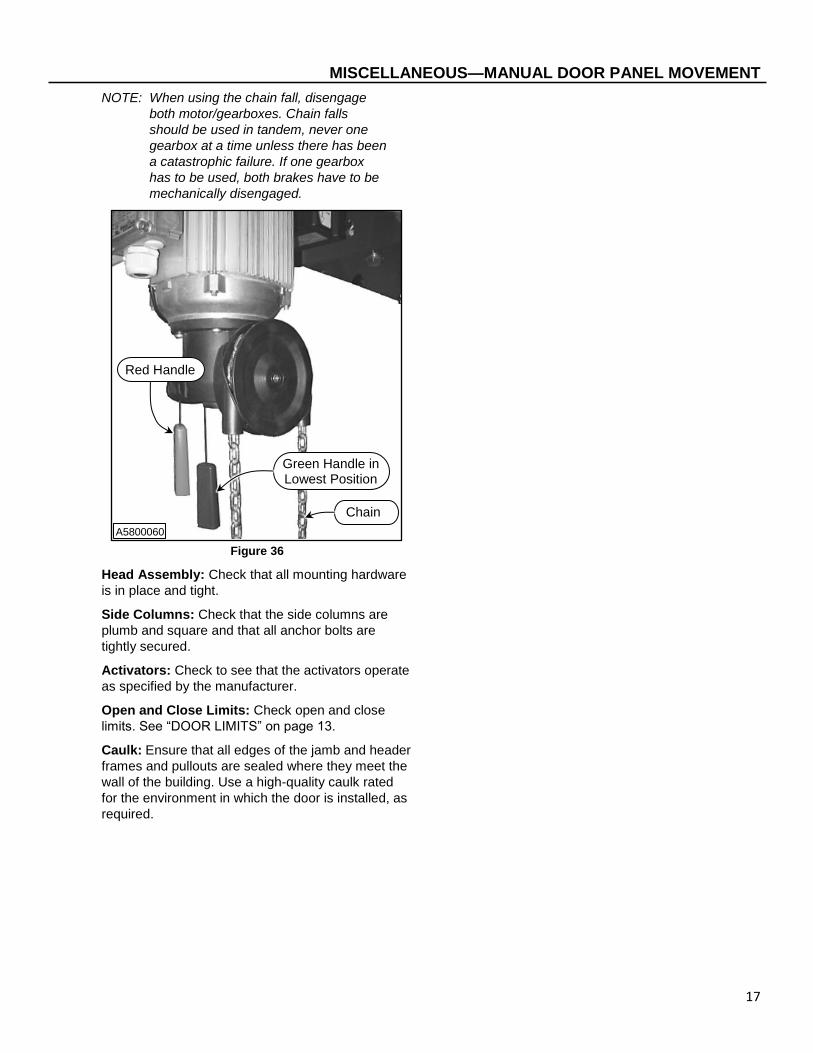
MISCELLANEOUS—MANUAL DOOR PANEL MOVEMENT
NOTE: When using the chain fall, disengage
both motor/gearboxes. Chain falls
should be used in tandem, never one
gearbox at a time unless there has been
a catastrophic failure. If one gearbox
has to be used, both brakes have to be
mechanically disengaged.
Figure 36
Head Assembly: Check that all mounting hardware
is in place and tight.
Side Columns: Check that the side columns are
plumb and square and that all anchor bolts are
tightly secured.
Activators: Check to see that the activators operate
as specified by the manufacturer.
Open and Close Limits: Check open and close
limits. See “DOOR LIMITS” on page 13.
Caulk: Ensure that all edges of the jamb and header
frames and pullouts are sealed where they meet the
wall of the building. Use a high-quality caulk rated
for the environment in which the door is installed, as
required.
Red Handle
Green Handle in Lowest Position
A5800060
Chain

18
WIRE SCHEMATIC—GENERAL
WIRE SCHEMATIC
GENERAL
Figure 37
A5800084

19
WIRE SCHEMATIC—GENERAL
Figure 38
A5800085
20
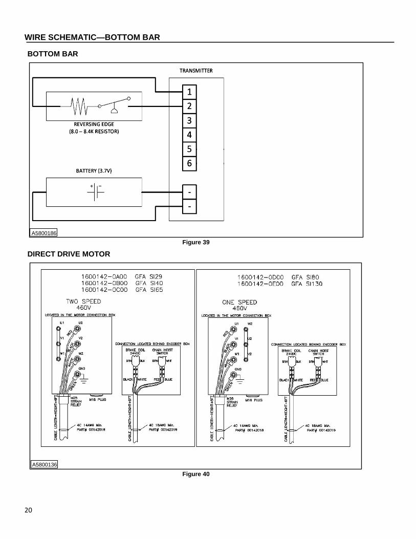
WIRE SCHEMATIC—BOTTOM BAR
BOTTOM BAR
Figure 39
DIRECT DRIVE MOTOR
Figure 40
A5800186
A5800136

21
WIRE SCHEMATIC—CHAIN DRIVE MOTOR
CHAIN DRIVE MOTOR
Figure 41
A5800134

22
NOTES

23
PARTS LIST—PARTS ORDERING INFORMATION
PARTS LIST
PARTS ORDERING INFORMATION
How to Order Parts
1. Identify the parts required by referring to the
following pages for part numbers and part
descriptions.
2. To place an order, contact your local Rytec
representative or the Rytec Technical Support
Department at 800-628-1909 or 262-677-2058
(fax). Rytec Corporation also has an on-line store
at WWW.Rytecparts.com access to this on-line
store requires an invitation from Rytec. The on-
line store is open 24/7, 365 days. Some items are
available to ship next day. Not all Rytec parts are
carried in the on-line store.
3. To ensure the correct parts are shipped, please
include the serial number of your door with the
order. The serial number is located on the door in
several locations per the “DOOR SERIAL
NUMBERS” section (See page 1). All these serial
numbers must match. (See Figure 41)
Figure 41
Substitute Parts
Due to special engineering and product
enhancement, the actual parts used on your door
may be different from those shown in this manual.
Also, if a part has been improved in design and
bears a revised part number, the improved part will
be substituted for the part ordered.
Return of Parts
Rytec will not accept the return of any parts unless
they are accompanied by a Return Merchandise
Authorization (RMA) form.
Before returning any parts, you must first contact the
Rytec Technical Support Department to obtain
authorization and an RMA number.
IMPORTANT: Obtain an incident number from
the Rytec Technical Support
Technician.
RYTEC TECHNCIAL KNOWLEDGE CENTER
At WWW.Rytecdoors.com under the “Contact Us”
pull down tab, a link to the Rytec Technical
Knowledge Center can be found by selecting the
“Customer Support” option. You will be directed to
the Customer Support webpage. Within the
“Technical Documents and Manuals” section you will
find the link “Rytec Technical Knowledge Center”.
This knowledge center contains on-line manuals,
service bulletins, and video presentations of various
Rytec models and repair information.
Head Assembly without Hood
Motor/Gearbox Assemblies
Rubber Door Panel with Bottom Bar
Right Side Column
Left Side Column
A5800074

24
PARTS LIST—REAR SPREADER WITH IDLER
REAR SPREADER WITH IDLER
Figure 43
2
1
2
3, 4, 5
3, 4, 6
7
8, 9, 10, 10, 11
8, 9, 10, 10, 12
13
1
15, 16, 16, 17, 18
22, 23, 24
20, 21
19
19
25
26

25
PARTS LIST—REAR SPREADER WITH IDLER
ITEM QTY. PART # DESCRIPTION
1 1 160078-0 Assembly, Rear Spreader
1600459-1E00 Assembly, Rear Spreader, E-Head, LH
1600459-2E00 Assembly, Rear Spreader, E-Head, RH
1600459-1F00 Assembly, Rear Spreader, F-Head, LH
1600459-2F00 Assembly, Rear Spreader, F-Head, RH
2 A/R 1600501-0 Support Angle, Spreader
3 A/R 0553229 Hex Lock Nut Serrated Flange, ³/₈-16
4 A/R 0555146 Washer, Flat, س/₈
5 A/R 5550192-0Z01 Hex Head Cap Screw, ³/₈-16 x 4.50
6 A/R 0550138 Hex Head Cap Screw, ³/₈-16 x 4.00
7 A/R 1600497-0 Weldment, Upper Strut
8 12 0553091 Nut, ³/₈-16
9 12 0554118 Washer, Split Lock, ³/₈-in.
10 24 0555146 Washer, Flat, ³/₈-in.
11 4 5550196-0Z01 Hex Head Cap Screw, ³/₈-16 x 7.00
12 8 5550138 Hex Head Cap Screw, ³/₈-16 x 4.00
13 A/R 0550016 Hex Flange Serrated Machine Screw, ¹/₄-20 x ³/₄
14
15 A/R 0550138 Hex Head Cap Screw, ³/₈-16 x 4.00
16 A/R 0555146 Washer, Flat, ³/₈-in.
17 A/R 0554118 Washer, Split Lock, ³/₈-in.
18 A/R 0553091 Nut, ³/₈-16
19 1 1600304-0E00 Assembly, Idler Roller, Single, E-Head
2 1600304-0F00 Assembly, Idler Roller, Dual, F-Head
20 1 1600465-0 Brush, Rear Spreader
21 1 1600466-0 Track, Aluminum
22 A/R 0555144 Washer, 0.781 x 1.50 x 0.120
23 A/R 0554184 Washer, Lock, ³/₄-in.
24 A/R 5550163-0Z01 Hex Head Cap Screw, ³/₄-10 x 2.75
25 A/R 1600560-0 Bearing, Idler Pillow Block, Vertical Zerk Fittings
26 2 5550124-0Z01 Shaft Collar, Split, 4.00 (OD) x 2.75 (ID) x .88 (T)
CF = Consult Factory
A/R = As Required
ALWAYS INCLUDE SERIAL NUMBER OF DOOR WHEN PLACING ORDER Due to product enhancement, the actual parts on your door may be different from those shown in this manual.
26
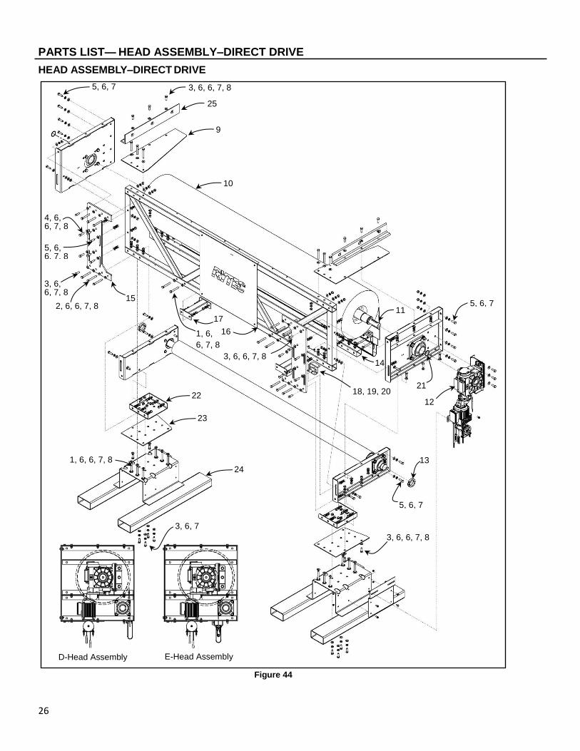
PARTS LIST— HEAD ASSEMBLY–DIRECT DRIVE
HEAD ASSEMBLY–DIRECT DRIVE
Figure 44
5, 6, 7 3, 6, 6, 7, 8
D-Head Assembly E-Head Assembly
25
9
3, 6, 6, 7, 8
5, 6, 6, 7, 8
4, 6, 6, 7, 8
3, 6, 6, 7, 8
2, 6, 6, 7, 8
17
16 1, 6,
6, 7, 8
18, 19, 20
12
10
11
13
15
22
23
5, 6, 7
5, 6, 7
3, 6, 7
1, 6, 6, 7, 8
3, 6, 6, 7, 8
24
14
21

27
PARTS LIST—HEAD ASSEMBLY–DIRECT DRIVE
ITEM QTY. PART # DESCRIPTION
1 38 5550176-0Z01 Hex Head Cap Screw, ⁵/₈-11 x 4.50
2 6 5550177-0Z01 Hex Head Cap Screw, ⁵/₈-11 x 5.00
3 32 5550175-0Z01 Hex Head Cap Screw, ⁵/₈-11 x 1.75
4 4 5550111-0Z01 Hex Head Cap Screw, ⁵/₈-11 x 2.25
5 10 5550170-0Z01 Hex Head Cap Screw, ⁵/₈-11 x 2.00
6 182 5550128-0Z01 Washer, Flat, ⁵/₈-in.
7 90 0554120 Washer, Lock, ⁵/₈-in.
8 80 0553092 Hex Nut, ⁵/₈-in. UNC
9 2 1600297-0 Top Plate, Head
10 1 Consult Factory Drum Assembly
11* 1 (REF) 1600152-0 Key, Shaft Motor Drive - *contained in Item 10
12 2 Consult Factory Motor-Gearbox
13 2 5550124-0Z01 Shaft Collar, Split, 4.00 (OD) x 2.75 (ID) x 0.88 (T)
14 1 1600316-0 Horizontal Truss, Lower
15 2 1600298-0 Front Plate, Head
16 1 1600313-0 Front Truss Assembly
17 2 1600476-0 Spreader Bar Tie-In
18 1 1600094-0 Antenna Bracket Assembly
19* 2 (REF) 5550134-0Z01 Hex Flanged Socket Mach. Screw 1/4-20 x 3.50 ZN
20* 2 (REF) 0553103 Nut, Hex Serrated Flanged Lock, 1/4-20 ZN
*Items 19 & 20 are contained in Item 18
21 2 5550161-0Z01 Snap Ring, 3.50 ID
22 2 1600421-0 Bottom Plate
23 2 1600401-0 Bottom Plate
24 2 1600833-X Cradle, Lifting
25 2 1600451-0Z01 Angle, Lifting
CF = Consult Factory
A/R = As Required
ALWAYS INCLUDE SERIAL NUMBER OF DOOR WHEN PLACING ORDER Due to product enhancement, the actual parts on your door may be different from those shown in this manual.

28
PARTS LIST— HEAD ASSEMBLY–CHAIN DRIVE
HEAD ASSEMBLY–CHAIN DRIVE
Figure 45
21 26
19 11
20
3, 6, 6, 7, 8
5, 6, 6, 7, 8
10
9
1, 6, 6, 7, 8
1, 6, 6, 7, 8
1, 6, 6, 7, 8
D-Head Assembly E-Head Assembly
3, 6, 6, 7, 8
1, 6, 6, 7, 8
3, 6, 6, 7, 8
4, 6, 6, 7, 8
5, 6, 6, 7, 8
2, 6, 6, 7, 8 16
17
12 22
23
1, 6, 6, 7, 8
5, 6, 6, 7, 8 14
3, 6, 6, 7, 8
1, 6, 6, 7, 8
15
3, 6, 6, 7, 8
5, 6, 6, 7, 8

29
PARTS LIST—HEAD ASSEMBLY–CHAIN DRIVE
ITEM QTY. PART # DESCRIPTION
1 38 5550176-0Z01 Hex Head Cap Screw, ⁵/₈-11 x 4.50
2 6 5550177-0Z01 Hex Head Cap Screw, ⁵/₈-11 x 5.00
3 32 5550175-0Z01 Hex Head Cap Screw, ⁵/₈-11 x 1.75
4 4 5550111-0Z01 Hex Head Cap Screw, ⁵/₈-11 x 2.25
5 10 5550170-0Z01 Hex Head Cap Screw, ⁵/₈-11 x 2.00
6 182 5550128-0Z01 Washer, Flat, ⁵/₈-in.
7 90 0554120 Washer, Lock, ⁵/₈-in.
8 80 0553092 Hex Nut, ⁵/₈-in. UNC
9 2 1600297-0 Top Plate, Head
10 1 Consult Factory Drum Assembly
11 2 1600370-0 Key, Large Sprocket
12 2 Consult Factory Motor-Gearbox
13 2 5550124-0Z01 Shaft Collar, Split, 4.00 (OD) x 2.75 (ID) x 0.88 (T)
14 1 1600316-0 Horizontal Truss, Lower
15 2 1600298-0 Front Plate, Head
16 1 1600313-0 Front Truss Assembly
17 2 1600476-0 Spreader Bar Tie-In
18 1 1600617-0 Assembly, ASO Wireless Receiver, Cord, and Hardware XL
19 2 1600329-0 Drum Sprocket, Dual Strand, 17T
20 2 1600829-0 Assembly, Proximity Sensor and Bracket
21 2 5550161-0Z01 Snap Ring, 3.50 ID
22 2 1600421-0 Bottom Plate
23 2 1600401-0 Bottom Plate
24 2 1600833-X Cradle, Lifting
25 2 1600451-0Z01 Angle, Lifting (Not Shown)
26 2 1600269-0 Chain, 72.50-in. long
27 2 1600833-X Cradle, Lifting (Not Shown)
CF = Consult Factory
A/R = As Required
ALWAYS INCLUDE SERIAL NUMBER OF DOOR WHEN PLACING ORDER Due to product enhancement, the actual parts on your door may be different from those shown in this manual.

30
PARTS LIST—SIDE COLUMN ASSEMBLY
SIDE COLUMN ASSEMBLY (“D” SIZE HEAD)
Figure 46
7, 8, 9
1
7, 8, 10
2
1
2 14, 15, 16
2
14, 15, 16
3, 4
SECTION A-A
5, 6
12
13
7, 8, 9
11

31
ALWAYS INCLUDE SERIAL NUMBER OF DOOR WHEN PLACING ORDER
To ensure you receive the correct parts when placing an order, always include the serial number of your door. Also,
due to product enhancement, the actual parts on your door may be different from those shown in this manual.
PARTS LIST—SIDE COLUMN ASSEMBLY
ITEM QTY. PART # DESCRIPTION
1 1 Consult Factory Weldment, LH Side Column
Consult Factory Weldment, RH Side Column
2 2 1600140-0 LED Assembly
3 1 00142010 LED Split Connector
4 1 0012807 Cable, M12 Micro Connector, 15 M, Female 5 Conductor
0012869 Cable, M12 Micro Connector, RKT 5-612-30M, Female
5† 1 0904030 Cable Clip, ⅜ ID
6† 1 0553103 Nut, ¼-20 UNC Hex Flanged Lock, ZN
7 8 5550128-0Z01 Washer, Flat, Ø⁵/₈-in. ZN
8 8 0554120 Washer, Lock, ⁵/₈-in.
9 6 5550170-0Z01 Hex Head Cap Screw, ⁵/₈-11 x 2.00, ZY
10* 2 5550178-0Z01 Hex Head Cap Screw, ⁵/₈-11 x 2.75, GR8, ZN
11 1 1600633-0 Wire Protector, Powerhouse
12 1 1600639-1 Guide, side column cover, 90° Windlock, LH
1600639-2 Guide, side column cover, 90° Windlock, RH
13 2 5550330 Hex Head Flanged Machine Screw, ⅜-16 x 1.00, GR5.2, ZN
14 A/R 5550145-0Z01 Hex Head Cap Screw, ⅜-16 x 1.00, GR8 ZN
15 A/R 5550140-0Z01 Washer, Flat ⅜ ID x 1.25 OD x 1/8 Thk, ZN
16 A/R 0554225 Washer, Split Lock, Ø⅜-in. SS
17 1 1600338-0 Cord Organizer, Spiral Wrapping (Not Shown)
18** 1 0553092 Nut, ⁵/₈-11 UNC Hex, ZN
19** 1 5550175-0Z01 Hex Head Cap Screw, ⁵/₈-11 x 1.75, GR5, ZN
CF = Consult Factory
A/R = As Required
N/A = not applicable to this assembly
† NOT Used only on “E” & “F” size Side Column Assembly
* Used only on “D” size head Side Column Assembly
** Used only on “E” & “F” size head Side Column Assembly
NOTE: Also refer to Figure 47.

32
PARTS LIST—SIDE COLUMN ASSEMBLY
SIDE COLUMN ASSEMBLY (“E” & “F” SIZE HEAD)
Figure 47
5, 6
1
2 14, 15, 16
SECTION A-A
2
13
2
14, 15, 16
3, 4
7, 8, 18, 19
11
7, 8, 9
1
12
Cable Exit Hole
33
ALWAYS INCLUDE SERIAL NUMBER OF DOOR WHEN PLACING ORDER
To ensure you receive the correct parts when placing an order, always include the serial number of your door. Also,
due to product enhancement, the actual parts on your door may be different from those shown in this manual.
PARTS LIST—SIDE COLUMN ASSEMBLY

34
PARTS LIST—HOOD ASSEMBLY
HOOD ASSEMBLY
Figure 48
3 1
1
2
2
2
2
1
1
2
2
1
1
1
1 1
1
1
1 1
1
1
1 2
2
2
2
2
2
2
12
2
2
13
14
2
2
2
2
2
15
16
2
22
2
17
18
20
19
21
A5800164
9, 10, 11
4 5
6
6
7
8
4

35
PARTS LIST—HOOD ASSEMBLY
ITEM QTY. PART # DESCRIPTION
1 60 5550209-0Z01 Hex Head Self Drilling Screw with Rubber Washer, ¹/₄-14 x ³/₄
2 38 0550016 Hex Flange Serrated Machine Screw, ¹/₄-20 x ³/₄
3 1 1600574-0 Flashing, Hood, Dual Drive
4 2 1600555-0 Hood, Outer
5 1 1600557-1 Hood, Inner, LH
6 2 1600559-0 Hood, Outer, Center
7 1 1600557-0 Hood, Inner, Center
8 1 1600557-2 Hood, Inner, RH
9 4 0550303 Hex Head Serrated Cap Screw, ¹/₂-13 x 1-¼
10 4 0554121 Washer, Split Lock, ¹/₂-in.
11 4 5550129-0Z01 Washer, Flat, ¹/₂-in.
12 1 1600548-1 Motor End Cover, LH, Dual Drive
13 1 1600551-1 Motor Cover, LH, Dual Drive
14 1 1600566-1 Front Cover, Hood, LH
15 1 1600566-0 Front Cover, Hood, Center
16 1 1600566-2 Front Cover, Hood, RH
17 1 1600551-2 Motor Cover, RH, Dual Drive
18 1 1600548-2 Motor End Cover, RH, Dual Drive
19 A/R 1600568-0 Rear Mounting Spreader Hood
20 2 1600553-1 Hood Frame, Dual Drive
21 8 1600553-0 Center Hood Frame, Dual Drive
22 8 0553103 Hex Flange Lock Nut, ¹/₄-20
CF = Consult Factory
A/R = As Required
ALWAYS INCLUDE SERIAL NUMBER OF DOOR WHEN PLACING ORDER Due to product enhancement, the actual parts on your door may be different from those shown in this manual.

36
PARTS LIST—DRUM AND DOOR PANEL ASSEMBLY
DRUM AND DOOR PANEL ASSEMBLY
Figure 49
4
5
2
1
3
3
2 1
A5800046

37
PARTS LIST—DRUM AND DOOR PANEL ASSEMBLY
DRUM AND DOOR PANEL ASSEMBLY
ITEM QTY. PART # DESCRIPTION
1 1 Consult Factory Drum Weldment
2 1 Consult Factory Panel Assembly
3 1 Consult Factory Bottom Bar Assembly
4 A/R 5550135-0Z01 Washer, Finish 3/8 in. Steel Plated
5 A/R 5550185-0Z01 Screw, Self-Tapping 5/16-18 X 2.00 Lng
CF = Consult Factory
A/R = As Required
ALWAYS INCLUDE SERIAL NUMBER OF DOOR WHEN PLACING ORDER Due to product enhancement, the actual parts on your door may be different from those shown in this manual.

38
PARTS LIST—BOTTOM BAR ASSEMBLY
BOTTOM BAR ASSEMBLY
Figure 50
A5800184
Detail “A”
Detail “B”
Detail “A”
Detail “B”
15
6
16
7
14 15
13
14
3
4
10
9
11
2
1
5
16
8
17
Detail “C”
Detail “C” (“F” Size Bottom Bar Shown)
11
12
10
13 21
6
18
9
39
PARTS LIST—BOTTOM BAR ASSEMBLY
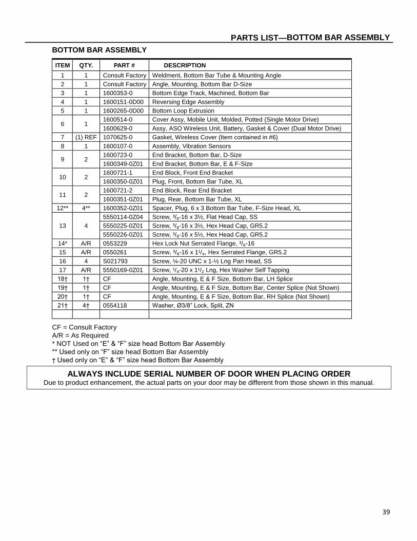
BOTTOM BAR ASSEMBLY
ITEM QTY. PART # DESCRIPTION
1 1 Consult Factory Weldment, Bottom Bar Tube & Mounting Angle
2 1 Consult Factory Angle, Mounting, Bottom Bar D-Size
3 1 1600353-0 Bottom Edge Track, Machined, Bottom Bar
4 1 1600151-0D00 Reversing Edge Assembly
5 1 1600265-0D00 Bottom Loop Extrusion
6 1 1600514-0 Cover Assy, Mobile Unit, Molded, Potted (Single Motor Drive)
1600629-0 Assy, ASO Wireless Unit, Battery, Gasket & Cover (Dual Motor Drive)
7 (1) REF 1070625-0 Gasket, Wireless Cover (Item contained in #6)
8 1 1600107-0 Assembly, Vibration Sensors
9 2 1600723-0 End Bracket, Bottom Bar, D-Size
1600349-0Z01 End Bracket, Bottom Bar, E & F-Size
10 2 1600721-1 End Block, Front End Bracket
1600350-0Z01 Plug, Front, Bottom Bar Tube, XL
11 2 1600721-2 End Block, Rear End Bracket
1600351-0Z01 Plug, Rear, Bottom Bar Tube, XL
12** 4** 1600352-0Z01 Spacer, Plug, 6 x 3 Bottom Bar Tube, F-Size Head, XL
13 4
5550114-0Z04 Screw, ³/₈-16 x 3½, Flat Head Cap, SS
5550225-0Z01 Screw, ³/₈-16 x 3½, Hex Head Cap, GR5.2
5550226-0Z01 Screw, ³/₈-16 x 5½, Hex Head Cap, GR5.2
14* A/R 0553229 Hex Lock Nut Serrated Flange, ³/₈-16
15 A/R 0550261 Screw, ³/₈-16 x 1¹/₄, Hex Serrated Flange, GR5.2
16 4 S021793 Screw, ¼-20 UNC x 1-½ Lng Pan Head, SS
17 A/R 5550169-0Z01 Screw, ¹/₄-20 x 1¹/₂ Lng, Hex Washer Self Tapping
18† 1† CF Angle, Mounting, E & F Size, Bottom Bar, LH Splice
19† 1† CF Angle, Mounting, E & F Size, Bottom Bar, Center Splice (Not Shown)
20† 1† CF Angle, Mounting, E & F Size, Bottom Bar, RH Splice (Not Shown)
21† 4† 0554118 Washer, Ø3/8” Lock, Split, ZN
CF = Consult Factory
A/R = As Required
* NOT Used on “E” & “F” size head Bottom Bar Assembly
** Used only on “F” size head Bottom Bar Assembly
† Used only on “E” & “F” size head Bottom Bar Assembly
ALWAYS INCLUDE SERIAL NUMBER OF DOOR WHEN PLACING ORDER Due to product enhancement, the actual parts on your door may be different from those shown in this manual.

40
PARTS LIST—BOTTOM BAR ASSEMBLY
BEARING PLATE ASSEMBLY
Figure 51
3
7
2
4
4
5
6
8
1
9 10
10
12
11
A5800150
41
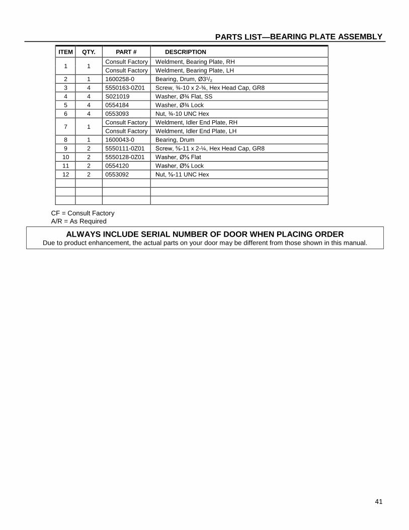
PARTS LIST—BEARING PLATE ASSEMBLY
ITEM QTY. PART # DESCRIPTION
1 1 Consult Factory Weldment, Bearing Plate, RH
Consult Factory Weldment, Bearing Plate, LH
2 1 1600258-0 Bearing, Drum, Ø3¹/₂
3 4 5550163-0Z01 Screw, ¾-10 x 2-¾, Hex Head Cap, GR8
4 4 S021019 Washer, ؾ Flat, SS
5 4 0554184 Washer, ؾ Lock
6 4 0553093 Nut, ¾-10 UNC Hex
7 1 Consult Factory Weldment, Idler End Plate, RH
Consult Factory Weldment, Idler End Plate, LH
8 1 1600043-0 Bearing, Drum
9 2 5550111-0Z01 Screw, ⅝-11 x 2-¼, Hex Head Cap, GR8
10 2 5550128-0Z01 Washer, Ø⅝ Flat
11 2 0554120 Washer, Ø⅝ Lock
12 2 0553092 Nut, ⅝-11 UNC Hex
CF = Consult Factory
A/R = As Required
ALWAYS INCLUDE SERIAL NUMBER OF DOOR WHEN PLACING ORDER Due to product enhancement, the actual parts on your door may be different from those shown in this manual.

42
PARTS LIST—MOTOR GEARBOX DIRECT DRIVE ASSEMBLY
MOTOR GEARBOX DIRECT DRIVE ASSEMBLY
Figure 52
3
9
2
4
7
6
8
1
9
10
11
12
INSTALLED ON FRONT SPREADER (Only Used on Single Drive Units)
A5800185
5
9
9
43
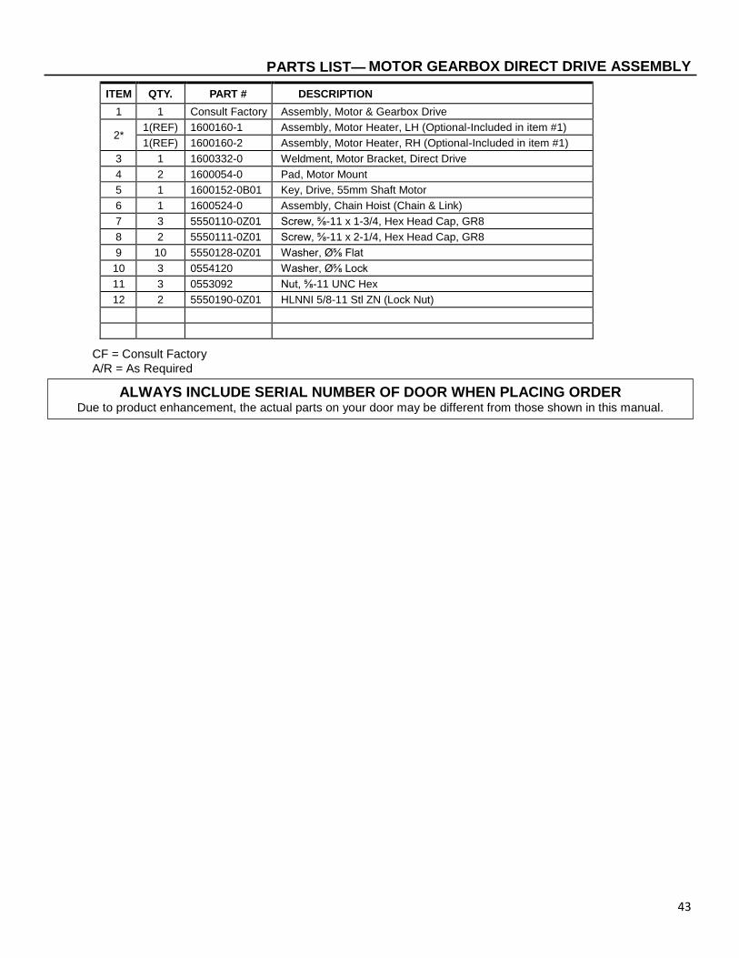
PARTS LIST— MOTOR GEARBOX DIRECT DRIVE ASSEMBLY
ITEM QTY. PART # DESCRIPTION
1 1 Consult Factory Assembly, Motor & Gearbox Drive
2* 1(REF) 1600160-1 Assembly, Motor Heater, LH (Optional-Included in item #1)
1(REF) 1600160-2 Assembly, Motor Heater, RH (Optional-Included in item #1)
3 1 1600332-0 Weldment, Motor Bracket, Direct Drive
4 2 1600054-0 Pad, Motor Mount
5 1 1600152-0B01 Key, Drive, 55mm Shaft Motor
6 1 1600524-0 Assembly, Chain Hoist (Chain & Link)
7 3 5550110-0Z01 Screw, ⅝-11 x 1-3/4, Hex Head Cap, GR8
8 2 5550111-0Z01 Screw, ⅝-11 x 2-1/4, Hex Head Cap, GR8
9 10 5550128-0Z01 Washer, Ø⅝ Flat
10 3 0554120 Washer, Ø⅝ Lock
11 3 0553092 Nut, ⅝-11 UNC Hex
12 2 5550190-0Z01 HLNNI 5/8-11 Stl ZN (Lock Nut)
CF = Consult Factory
A/R = As Required
ALWAYS INCLUDE SERIAL NUMBER OF DOOR WHEN PLACING ORDER Due to product enhancement, the actual parts on your door may be different from those shown in this manual.

44
PARTS LIST—MOTOR GEARBOX CHAIN DRIVE ASSEMBLY
MOTOR GEARBOX CHAIN DRIVE ASSEMBLY
Figure 53
4
10
2
5
8
7
9
1
6
A5800043
6
11
3
12

45
PARTS LIST—MOTOR GEARBOX CHAIN DRIVE ASSEMBLY
ITEM QTY. PART # DESCRIPTION
1 1 Consult Factory Assembly, Motor & Gearbox Drive
2* 1(REF) 1600160-1 Assembly, Motor Heater, LH (Optional-Included in item #1)
1(REF) 1600160-2 Assembly, Motor Heater, RH (Optional-Included in item #1)
3 1 1600270-0Z01 Motor Shaft, Chain Drive
4 1 1600328-0 Motor Sprocket, Machined, RS100 Dual Strand Chain, 12T
5 1 1600524-0 Assembly, Chain Hoist (Chain & Link)
6 2 5550162-0Z01 Snap Ring, RR Ext. M55ID
7 1 1600371-0Z01 Key, Small Sprocket
8 1 1600152-0Z01 Key, Drive, 55mm Shaft Motor
9 4 5550111-0Z01 Screw, ⅝-11 x 2-1/4, Hex Head Cap, GR8
10 8 5550128-0Z01 Washer, Ø⅝ Flat
11 4 0554120 Washer, Ø⅝ Lock
12 4 0553092 Nut, ⅝-11 UNC Hex
CF = Consult Factory
A/R = As Required
ALWAYS INCLUDE SERIAL NUMBER OF DOOR WHEN PLACING ORDER Due to product enhancement, the actual parts on your door may be different from those shown in this manual.

46
NOTES

47