Embed Size (px)
Citation preview
Pharma Slide Controller
iMotion
Installation & Owner’s Manual
®
®
[Revision: July 26, 2010, 1120295-0, ©Rytec Corporation, 2010]

TABLE OF CONTENTS
PAGE
INTRODUCTION. . . . . . . . . . . . . . . . . . . . . . . . . . . . . . . . . . . . . . . . . . . . .1
DOOR SERIAL NUMBER(S). . . . . . . . . . . . . . . . . . . . . . . . . . . . . . . . . . . . . . . . . . .1
HOW TO USE MANUAL . . . . . . . . . . . . . . . . . . . . . . . . . . . . . . . . . . . . . . . . . . . . . .1
REQUIREMENTS . . . . . . . . . . . . . . . . . . . . . . . . . . . . . . . . . . . . . . . . . . . . . . . . . . .2
Labor and Site Requirements. . . . . . . . . . . . . . . . . . . . . . . . . . . . . . . . . . . . .2
Electrician’s Responsibilities . . . . . . . . . . . . . . . . . . . . . . . . . . . . . . . . . . . . .2
GENERAL SAFETY INSTRUCTIONS . . . . . . . . . . . . . . . . . . . . . . . . . . . . . . . . . . .2
Preventing General Hazards and Possible Damage to Equipment. . . . . . .2
Warnings of Dangerous Electrical Voltages or Current . . . . . . . . . . . . . . . .2
APPLICATION . . . . . . . . . . . . . . . . . . . . . . . . . . . . . . . . . . . . . . . . . . . . . . . . . . . . . .2
PRECAUTIONARY MEASURES. . . . . . . . . . . . . . . . . . . . . . . . . . . . . . . . . . . . . . . .2
GENERAL MEASURES . . . . . . . . . . . . . . . . . . . . . . . . . . . . . . . . . . . . . . . . . . . . . .3
SAFETY DEVICES . . . . . . . . . . . . . . . . . . . . . . . . . . . . . . . . . . . . . . . . . . . . . . . . . .3
Self-Checking Photoeye Function . . . . . . . . . . . . . . . . . . . . . . . . . . . . . . . . .3
Electronic Reversing Function. . . . . . . . . . . . . . . . . . . . . . . . . . . . . . . . . . . .3
OPERATION OF DOOR . . . . . . . . . . . . . . . . . . . . . . . . . . . . . . . . . . . . . . . . . . . . . .3
SYSTEM OVERVIEW . . . . . . . . . . . . . . . . . . . . . . . . . . . . . . . . . . . . . . . . .4
CONTROL PANEL. . . . . . . . . . . . . . . . . . . . . . . . . . . . . . . . . . . . . . . . . . . . . . . . . . .4
NORMAL OPERATION . . . . . . . . . . . . . . . . . . . . . . . . . . . . . . . . . . . . . . . . . . . . . . .4
PHOTO EYE . . . . . . . . . . . . . . . . . . . . . . . . . . . . . . . . . . . . . . . . . . . . . . . . . . . . . . .4
OPERATING MODES . . . . . . . . . . . . . . . . . . . . . . . . . . . . . . . . . . . . . . . . . . . . . . . .4
Operating Mode OFF. . . . . . . . . . . . . . . . . . . . . . . . . . . . . . . . . . . . . . . . . . . .4
Operating Mode AUTOMATIC 1 . . . . . . . . . . . . . . . . . . . . . . . . . . . . . . . . . . .5
Operating Mode AUTOMATIC 2 . . . . . . . . . . . . . . . . . . . . . . . . . . . . . . . . . . .5
Operating Mode EXIT . . . . . . . . . . . . . . . . . . . . . . . . . . . . . . . . . . . . . . . . . . .6
Operating Mode OPEN . . . . . . . . . . . . . . . . . . . . . . . . . . . . . . . . . . . . . . . . . .6
Operating Mode P (Manual Operation) . . . . . . . . . . . . . . . . . . . . . . . . . . . . .7
AUTOMATIC DOOR OPERATION WITH SENSORS . . . . . . . . . . . . . . . . . . . . . . . .7
CONTROL PANEL OPERATION . . . . . . . . . . . . . . . . . . . . . . . . . . . . . . . .7
TERMINAL CONNECTION . . . . . . . . . . . . . . . . . . . . . . . . . . . . . . . . . . . . . . . . . . . .7
INITIAL START-UP . . . . . . . . . . . . . . . . . . . . . . . . . . . . . . . . . . . . . . . . . . . . . . . . . .9
CONTROL PANEL PROGRAMMING . . . . . . . . . . . . . . . . . . . . . . . . . . . . . . . . . . . .9
Start Access Code. . . . . . . . . . . . . . . . . . . . . . . . . . . . . . . . . . . . . . . . . . . . . .9
Entering Access Code . . . . . . . . . . . . . . . . . . . . . . . . . . . . . . . . . . . . . . . . .10
Start Programming Level . . . . . . . . . . . . . . . . . . . . . . . . . . . . . . . . . . . . . . .10
Entering Parameter Code . . . . . . . . . . . . . . . . . . . . . . . . . . . . . . . . . . . . . . .10
Time-Out. . . . . . . . . . . . . . . . . . . . . . . . . . . . . . . . . . . . . . . . . . . . . . . . . . . . .11
Exiting Programming Level . . . . . . . . . . . . . . . . . . . . . . . . . . . . . . . . . . . . .11
PROGRAMMING EXAMPLE . . . . . . . . . . . . . . . . . . . . . . . . . . . . . . . . .11
PROGRAMMING CODES . . . . . . . . . . . . . . . . . . . . . . . . . . . . . . . . . . . .12
TROUBLESHOOTING . . . . . . . . . . . . . . . . . . . . . . . . . . . . . . . . . . . . . . .20
DISPLAY AND RESET CONTROL PANEL. . . . . . . . . . . . . . . . . . . . . . . . . . . . . . .20
Control Panel Fault Reset — Power Supply . . . . . . . . . . . . . . . . . . . . . . . .20
GENERAL FAULT CODES . . . . . . . . . . . . . . . . . . . . . . . . . . . . . . . . . . . . . . . . . . .21
TROUBLESHOOTING . . . . . . . . . . . . . . . . . . . . . . . . . . . . . . . . . . . . . . .24
TROUBLESHOOTING WITH LEDS . . . . . . . . . . . . . . . . . . . . . . . . . . . . . . . . . . . .24
Battery Module. . . . . . . . . . . . . . . . . . . . . . . . . . . . . . . . . . . . . . . . . . . . . . . .24
Functions . . . . . . . . . . . . . . . . . . . . . . . . . . . . . . . . . . . . . . . . . . . . . . . . . . . .24
Periodic Tests . . . . . . . . . . . . . . . . . . . . . . . . . . . . . . . . . . . . . . . . . . . . . . . .24
Power Failure/Voltage Variations . . . . . . . . . . . . . . . . . . . . . . . . . . . . . . . . .24
Power Recovery. . . . . . . . . . . . . . . . . . . . . . . . . . . . . . . . . . . . . . . . . . . . . . .24
Programmable Functions . . . . . . . . . . . . . . . . . . . . . . . . . . . . . . . . . . . . . . .24
LED Display . . . . . . . . . . . . . . . . . . . . . . . . . . . . . . . . . . . . . . . . . . . . . . . . . .25
SPECIFICATIONS . . . . . . . . . . . . . . . . . . . . . . . . . . . . . . . . . . . . . . . . . .27
MECHANICAL. . . . . . . . . . . . . . . . . . . . . . . . . . . . . . . . . . . . . . . . . . . . . . . . . . . . .27
INPUTS . . . . . . . . . . . . . . . . . . . . . . . . . . . . . . . . . . . . . . . . . . . . . . . . . . . . . . . . . .27
OUTPUTS . . . . . . . . . . . . . . . . . . . . . . . . . . . . . . . . . . . . . . . . . . . . . . . . . . . . . . . .27
ABBREVIATIONS . . . . . . . . . . . . . . . . . . . . . . . . . . . . . . . . . . . . . . . . . . . . . . . . . .28
SCHEMATICS. . . . . . . . . . . . . . . . . . . . . . . . . . . . . . . . . . . . . . . . . . . . . .29
GENERAL . . . . . . . . . . . . . . . . . . . . . . . . . . . . . . . . . . . . . . . . . . . . . . . . . . . . . . . .29
GENERAL (SHEET 2) . . . . . . . . . . . . . . . . . . . . . . . . . . . . . . . . . . . . . . . . . . . . . . .30
PARTS LIST . . . . . . . . . . . . . . . . . . . . . . . . . . . . . . . . . . . . . . . . . . . . . . .32
PARTS ORDERING INFORMATION. . . . . . . . . . . . . . . . . . . . . . . . . . . . . . . . . . . .32
How to Order Parts . . . . . . . . . . . . . . . . . . . . . . . . . . . . . . . . . . . . . . . . . . . .32
Substitute Parts . . . . . . . . . . . . . . . . . . . . . . . . . . . . . . . . . . . . . . . . . . . . . . .32
Return of Parts. . . . . . . . . . . . . . . . . . . . . . . . . . . . . . . . . . . . . . . . . . . . . . . .32
DOOR SERIAL NUMBER(S). . . . . . . . . . . . . . . . . . . . . . . . . . . . . . . . . . . . . . . . . .32
CONTROL PANEL. . . . . . . . . . . . . . . . . . . . . . . . . . . . . . . . . . . . . . . . . . . . . . . . . .33

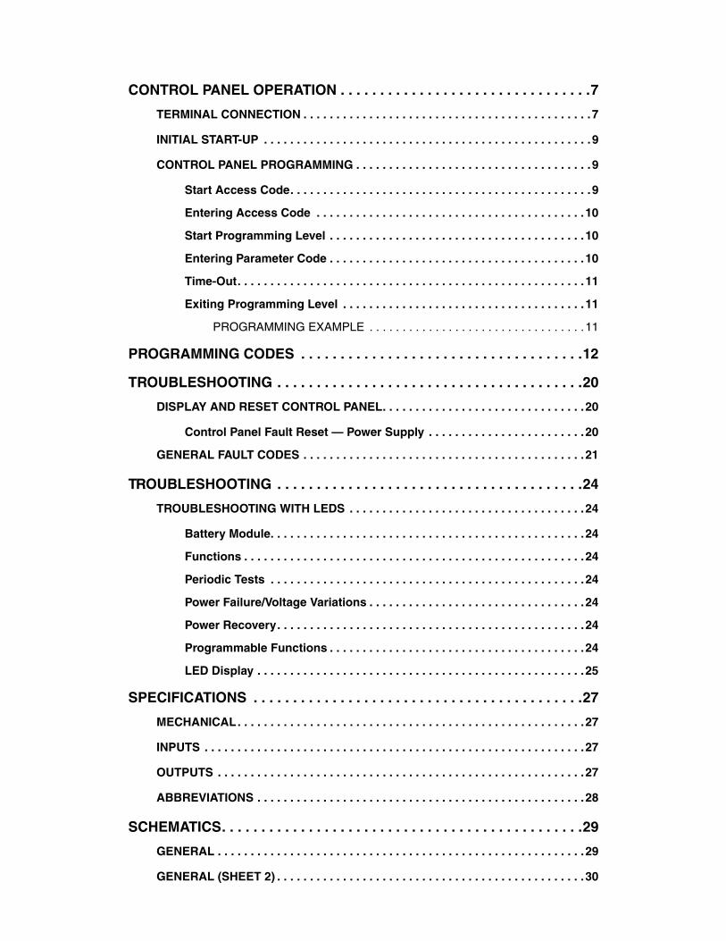
INTRODUCTION—DOOR SERIAL NUMBER(S)
INTRODUCTIONThe information contained in this manual will allow you
to operate and maintain the TORMAX® automatic oper-ator in a manner that will ensure maximum life and trouble-free operation.
TORMAX® is a division and a registered trademark of Landert Motoren AG. iMotion® is a registered trademark of TORMAX.
NOTE: This manual is intended for the TORMAXoperator only. Installation and operationinformation specific to your door isdetailed in the installation and owner’smanuals that were shipped with the door.
Any unauthorized changes to these procedures, or fail-ure to follow the steps as outlined, will automatically void the warranty. Any changes to the working parts, assemblies, or specifications as written, not authorized by Rytec Corporation, will also void the warranty. The responsibility for the successful operation and perfor-mance of this drive and control system lies with the owner of the door.
DO NOT INSTALL, OPERATE, OR PERFORM MAIN-TENANCE ON THIS DRIVE AND CONTROL SYSTEM UNTIL YOU READ AND UNDERSTAND THE INSTRUCTIONS IN THIS MANUAL.
If you have any questions, contact your Rytec represen-tative or call the Rytec Customer Support Department at 800-628-1909. Always refer to the serial number of the door that your control system is connected to when calling the representative or Customer Support. Refer to the installation manual or the owner’s manual provided with your door for the location of the serial number plate.
The wiring connections and schematics in this manual are for general information purposes only. A wiring schematic is provided with each individual door, specif-ically covering the control panel and electrical compo-nents of that door.
DOOR SERIAL NUMBER(S)
The DOOR SERIAL NUMBER is located on the left side of the head assembly. (See Figure 1.)
IMPORTANT: When installing multiple doorsof the same model but in differ-ent sizes, verify the serial num-ber in the head assembly.
Figure 1
HOW TO USE MANUAL
Throughout this manual, the following key words are used to alert the reader of potentially hazardous situa-tions, or situations where additional information to suc-cessfully perform the procedure is presented:
WARNING is used to indicate the potentialfor personal injury, if the procedure is notperformed as described.
CAUTION is used to indicate the potentialfor damage to the product or propertydamage, if the procedure is not followedas described.
IMPORTANT: IMPORTANT is used to relayinformation CRITICAL to thesuccessful completion of theprocedure.
NOTE: NOTE is used to provide additional infor-mation to aid in the performance of theprocedure or operation of the door, but notnecessarily safety related.
Serial Number
A3100224
End
HeadAssembly
Seal Stop Column
Column
Tormax Control Drive withHood Half Removed
Door Panel
with Wall Jamb
Location
1
INTRODUCTION—REQUIREMENTS
REQUIREMENTS
Labor and Site Requirements
1. An electrician is required for all electrical connec-tions. (See “Electrician’s Responsibilities” below.)
IMPORTANT: All electrical work must be per-formed in accordance with localand state building codes.
2. Unlimited accessibility to the door opening is essen-tial during the installation process. Traffic should not pass through the opening during the installation procedure.
Electrician’s Responsibilities
1. Furnish and install fused disconnect(s).
2. Install all necessary conduit.
3. Run electrical power lines to fused disconnect.
4. Run power lines from disconnect to control panel.
5. Run power and control lines from control panel to door head assembly (and defrost system, if used).
6. Install conduit from control panel to floor for floor loop activators and wire activators (if used).
GENERAL SAFETY INSTRUCTIONS
Please read the operating instructions carefully prior to installation or commissioning. Damage to the unit and personal injury may result if these instructions are not carefully followed.
Preventing General Hazards and Possible Damage to Equipment
• Keep fingers away from moving parts.
• Verify that the power selection switch is set to the correct voltage before start-up.
• The power supply cable (flexible cord) should be inserted at the side that is closer to the input power supply plug. It should not be routed through door-ways, window openings, walls, ceilings, floors, etc. The power supply cable (flexible cord) should not be attached or otherwise secured to the building struc-ture. It also should not be concealed behind walls, etc.
• Never allow the power supply cable (flexible cord) to become entrapped on moving parts of the operator, door, or system.
• The power receptacle must be of the grounding type. It is very important for the unit to be properly grounded.
• To reduce the risk of electrical shock, this equip-ment has a grounding-type plug that has a third grounding pin. This plug will only fit into a ground-ing-type outlet. If the plug does not fit into the outlet, contact a qualified electrician to install the proper outlet. Do not change the plug in any way.
Warnings of Dangerous Electrical Voltages or Current
• Be sure the electrical power is disconnected and locked out when working on the operator unit.
• Install the electrical cables and power only after the mechanical installation to the unit is done.
• Turn on the power to the operator unit only after all internal cables are connected. Do not connect cables while the unit is powered.
• Always use appropriate tools for installation and repair.
APPLICATION
The TORMAX operator has been designed and manu-factured according to state-of-the-art engineering and recognized safety-related regulations and is intended exclusively for the operation of automatic Pharma Slide doors. Operators corresponding to IP 22 in the protec-tive system may only be installed at the inside of build-ings if no additional protective measures are provided.
Any other use is considered non-permissible and may result in injuries to the user or third parties. The manu-facturer will not be liable for damages resulting from incorrect application. The risk of such non-permissible applications must be borne solely and entirely by the owner of the door system.
This manual is applicable for Pharma Slide doors with TORMAX automatic door operator types:
• iMotion 2301 Sliding Door Drive
• iMotion 2401 Sliding Door Drive
PRECAUTIONARY MEASURES
Do not use the system in other than technically perfect condition. Make sure that faults which would impair safety are eliminated immediately by professionals.
The following are consequences of incorrect application of the door operator or the door system:
• Danger of the user’s or a third party’s injury or loss of life.
• Risk of damage to the system or associated equip-ment.
The operating service and maintenance conditions specified by the manufacturer are to be observed. TORMAX operator units must be maintained and repaired only by trained specialists who are aware of any possible danger that may occur.
2

INTRODUCTION—GENERAL MEASURES
In addition to the operating instructions, the generally accepted legal and otherwise relevant rules relating to accident prevention and to occupational medicine – in the country where the door system is installed – are also applicable.
NOTE: The manufacturer is exempt from any lia-bility for damages caused by unauthorizedalterations of the system.
GENERAL MEASURES
Doors are to be maintained in such a way that the safety of the user, maintenance personnel, or third party is guaranteed at all times.
Should any fault occur on the safety devices (e.g., safety beams), they may not be bypassed to maintain the auto-matic door functions.
The person operating, checking, or maintaining door systems must have the relevant operating instructions present.
Personnel charged with duties on the door system must have read and understood the operating instructions prior to performing any work.
Any mechanical or electrical work done on the door and the control systems may be performed by trained spe-cialists or contractors after consulting our trained spe-cialists.
SAFETY DEVICES
There are two self-checking safety beams (photocells) in the passageway.
Self-Checking Photoeye Function
Every interruption of the light beam of a photoeye causes the immediate termination of a closing action. If after 1 minute the light beam is still interrupted (for example, on a fault), then the door continues to operate in a safety mode – that is, with a slow closing speed.
During the opening and closing actions, the door move-ments are monitored by a sensitive electronic circuit.
NOTE: The controller may flash E31, E32, E33, orE34, indicating a photoeye may be inoper-ative or out of alignment. (See “GENERALFAULT CODES” on page 21.)
Electronic Reversing Function
If the door hits an obstacle during closing, it reopens, remains open somewhat longer, and closes again with reduced speed (the overrun distance in the area subject to jamming is 1 inch maximum).
If the door hits an obstacle during opening, it reverses and runs in closing direction for a few inches, stops for a while, and closes (opens, if sensor is active) with reduced speed.
OPERATION OF DOOR
When power is first applied to the unit, a calibration run will begin. The control panel will indicate H61 and H62. The door will travel at a slow speed to the fully open position, finding the end stop. Then the door will close at slow speed until the closed position is calibrated. After the door limits have been set, operate the door using the small blue SW2 switch located on the bottom right cor-ner of the circuit board. (See Figure 2.) The door is now ready for use and custom programming.
NOTE: The code H65 will appear as the door trav-els. It may take up to 15 cycles for the codeto leave the display. H65 indicates the con-troller is learning the door mass or weight.
Figure 2
A5600035
Blue SW2 Switch
3
SYSTEM OVERVIEW—CONTROL PANEL
SYSTEM OVERVIEW
CONTROL PANEL
The TORMAX iMotion control panel and automatic operator are specifically used in the Pharma Slide series of doors.
NORMAL OPERATION
Activation for the door can be done with push buttons, motion detectors, or pull cords.
The activation can be wired for automatic closure or reactivate to close.
If an opening activator is activated, the door opens, stops for the duration of the hold-open time, and closes again.
If, for example, the motion detector or safety photocells recognize a person while the door is open, the door will remain open. If a person moves within range of the motion detector, in the direction of the closing door, the door reopens immediately.
The door system may be operated only if all safety rele-vant devices are installed and functional.
PHOTO EYE
Your door is equipped with four photo eyes mounted on the front of the door. The purpose of these photo eyes is to hold the door open or, if the door is closing, reverse the door to the open position if a vehicle, person, or any object is in the path of the photo eye beam.
The photo eye is not active when the door is closed. After the obstruction breaking the photo eye beam is removed:
• The door will remain open if it was originally opened by a non-automatic activator until it is closed by a non-automatic activator.
• The door will close automatically if it was originally opened with an automatic activator.
NOTE: The photo eyes are not intended to beused as a door activator and will not openthe door when it is closed.
This safety system consists of two pairs of non-adjustable emitter and receiver modules. There are no alignment, gain, or sensitivity settings.
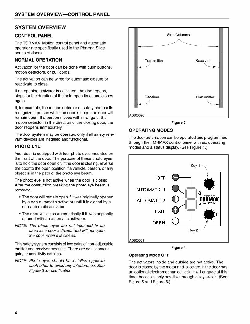
NOTE: Photo eyes should be installed oppositeeach other to avoid any interference. SeeFigure 3 for clarification.
Figure 3
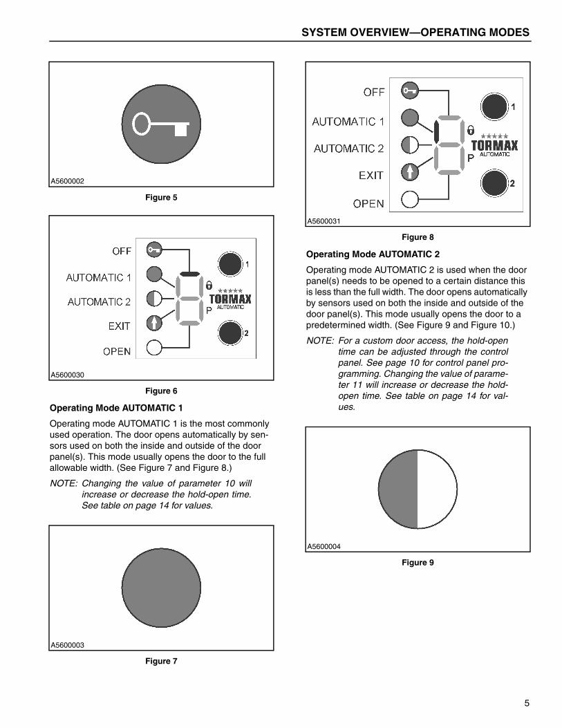
OPERATING MODES
The door automation can be operated and programmed through the TORMAX control panel with six operating modes and a status display. (See Figure 4.)
Figure 4
Operating Mode OFF
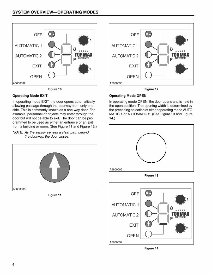
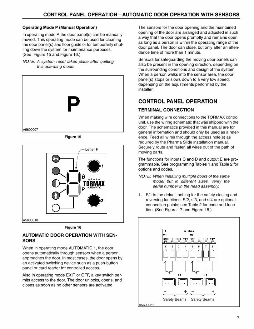
The activators inside and outside are not active. The door is closed by the motor and is locked. If the door has an optional electromechanical lock, it will engage at this time. Access is only possible through a key switch. (See Figure 5 and Figure 6.)
A5600026
Receiver
Transmitter
Transmitter
Receiver
Side Columns
A5600001
Key 1
Key 2
4
SYSTEM OVERVIEW—OPERATING MODES
Figure 5
Figure 6
Operating Mode AUTOMATIC 1
Operating mode AUTOMATIC 1 is the most commonly used operation. The door opens automatically by sen-sors used on both the inside and outside of the door panel(s). This mode usually opens the door to the full allowable width. (See Figure 7 and Figure 8.)
NOTE: Changing the value of parameter 10 willincrease or decrease the hold-open time.See table on page 14 for values.
Figure 7
Figure 8
Operating Mode AUTOMATIC 2
Operating mode AUTOMATIC 2 is used when the door panel(s) needs to be opened to a certain distance this is less than the full width. The door opens automatically by sensors used on both the inside and outside of the door panel(s). This mode usually opens the door to a predetermined width. (See Figure 9 and Figure 10.)
NOTE: For a custom door access, the hold-opentime can be adjusted through the controlpanel. See page 10 for control panel pro-gramming. Changing the value of parame-ter 11 will increase or decrease the hold-open time. See table on page 14 for val-ues.
Figure 9
A5600002
A5600030
A5600003
A5600031
A5600004
5
SYSTEM OVERVIEW—OPERATING MODES
Figure 10
Operating Mode EXIT
In operating mode EXIT, the door opens automatically allowing passage through the doorway from only one side. This is commonly known as a one-way door. For example, personnel or objects may enter through the door but will not be able to exit. The door can be pro-grammed to be used as either an entrance or an exit from a building or room. (See Figure 11 and Figure 12.)
NOTE: As the sensor senses a clear path behindthe doorway, the door closes.
Figure 11
Figure 12
Operating Mode OPEN
In operating mode OPEN, the door opens and is held in the open position. The opening width is determined by the preceding selection of either operating mode AUTO-MATIC 1 or AUTOMATIC 2. (See Figure 13 and Figure 14.)
Figure 13
Figure 14
A5600032
A5600005
A5600033
A5600006
A5600034
6
CONTROL PANEL OPERATION—AUTOMATIC DOOR OPERATION WITH SENSORS
Operating Mode P (Manual Operation)
In operating mode P, the door panel(s) can be manually moved. This operating mode can be used for cleaning the door panel(s) and floor guide or for temporarily shut-ting down the system for maintenance purposes. (See Figure 15 and Figure 16.)
NOTE: A system reset takes place after quittingthis operating mode.
Figure 15
Figure 16
AUTOMATIC DOOR OPERATION WITH SEN-SORS
When in operating mode AUTOMATIC 1, the door opens automatically through sensors when a person approaches the door. In most cases, the door opens by an activated switching device such as a push-button panel or card reader for controlled access.
Also in operating mode EXIT or OFF, a key switch per-mits access to the door. The door unlocks, opens, and closes as soon as no other sensors are activated.
The sensors for the door opening and the maintained opening of the door are arranged and adjusted in such a way that the door opens promptly and remains open as long as a person is within the operating range of the door panel. The door can close, but only after an atten-dance time of more than 1 minute.
Sensors for safeguarding the moving door panels can also be present in the opening direction, depending on the surrounding conditions and design of the system. When a person walks into the sensor area, the door panel(s) stops or slows down to a very low speed, depending on the adjustments performed by the installer.
CONTROL PANEL OPERATION
TERMINAL CONNECTION
When making wire connections to the TORMAX control unit, use the wiring schematic that was shipped with the door. The schematics provided in this manual are for general information and should only be used as a refer-ence. Feed all wires through the access hole(s) as required by the Pharma Slide installation manual. Securely route and fasten all wires out of the path of moving parts.
The functions for inputs C and D and output E are pro-grammable. See programming Tables 1 and Table 2 for options and codes.
NOTE: When installing multiple doors of the samemodel but in different sizes, verify theserial number in the head assembly.
1. Sf1 is the default setting for the safety closing and reversing functions. Sf2, sf3, and sf4 are optional connection points; see Table 2 for code and func-tion. (See Figure 17 and Figure 18.)
A5600007
A5600010
Letter P
A5600021
Safety Beams Safety Beams
7

CONTROL PANEL OPERATION—TERMINAL CONNECTION
Figure 17
Figure 18
2. Inputs C1 and C2 are connections for the inside activators, and inputs C4 and C5 are connections for the outside activators. (See Figure 19 and Figure 20.) D1 and D2 key switch activates the door open in all operating modes except mode P.
NOTE: Activation signals are inhibited when theFCP (Function Control Panel) is in modeEXIT and the door is fully closed.
Figure 19
Figure 20
3. There are two outputs provided with the iMotion operators. Output 1 is defaulted to Bell. Output 2 is defaulted to Door Closed. Adjustments can be made to parameter 68 for Output 1 and parameter 69 for Output 2. See the table on page 18 for Output 1 and Output 2 options. The output becomes active when the condition is met.
Figure 21
A5600022
Safety Beams Safety Beams
A5600023
Inside OutsideActivator Activator
A5600024
Key OffModeSwitch
A5600025Bell Messages
8
CONTROL PANEL OPERATION—INITIAL START-UP
INITIAL START-UP
IMPORTANT: During initial start-up it is veryimportant not to block the photoeyes or any activate sensors onthe door. On start-up the control-ler sets the inputs to look for nor-mally open or normally closedcontacts. If the sensor is in anactive state, the controller maychoose the settings to operatebackwards. See page 12 parame-ters 03 8 to reset inputs.
Prior to switching the power on:
• Unlock any locking mechanisms; e.g. floor lock.
• Make sure that the operating range of the door panel(s) is free and clear of any obstructions.
• Check if the floor guide is clean; e.g. pebbles.
• Switch on main power and select the operating mode.
NOTE: The door motion will be slow after switch-ing on the main power supply for the firsttime. The control panel will indicate H61and H62, which is determining the endstops for the door panel.
• The door is now ready for use.
When power is applied to the operator, the door will begin to commission and set the door open and close limits. The door will operate very slowly until the limits have been set. The control panel will display H61 and H62 during the commissioning process. This is the nor-mal operating mode.
NOTE: If the door will not commission, turn off thepower and move the door panel(s) manu-ally to check for binding. The panel(s)should move freely. If the door panel isbinding, adjust the trolley(s) or drive beltuntil a smooth operation is obtained.When you have finished the adjustments,turn on the power and the door will gothrough the commissioning process again.
CONTROL PANEL PROGRAMMING
The programming level can only be reached when the access code is entered. Without the access code, any unauthorized programming of the system is then elimi-nated. The starting value on the control panel is 0 and goes through 9 and then back to 0. Pressing Key 1 will increase the numerical value by 1 and pressing Key 2 will confirm the selection.
Start Access Code
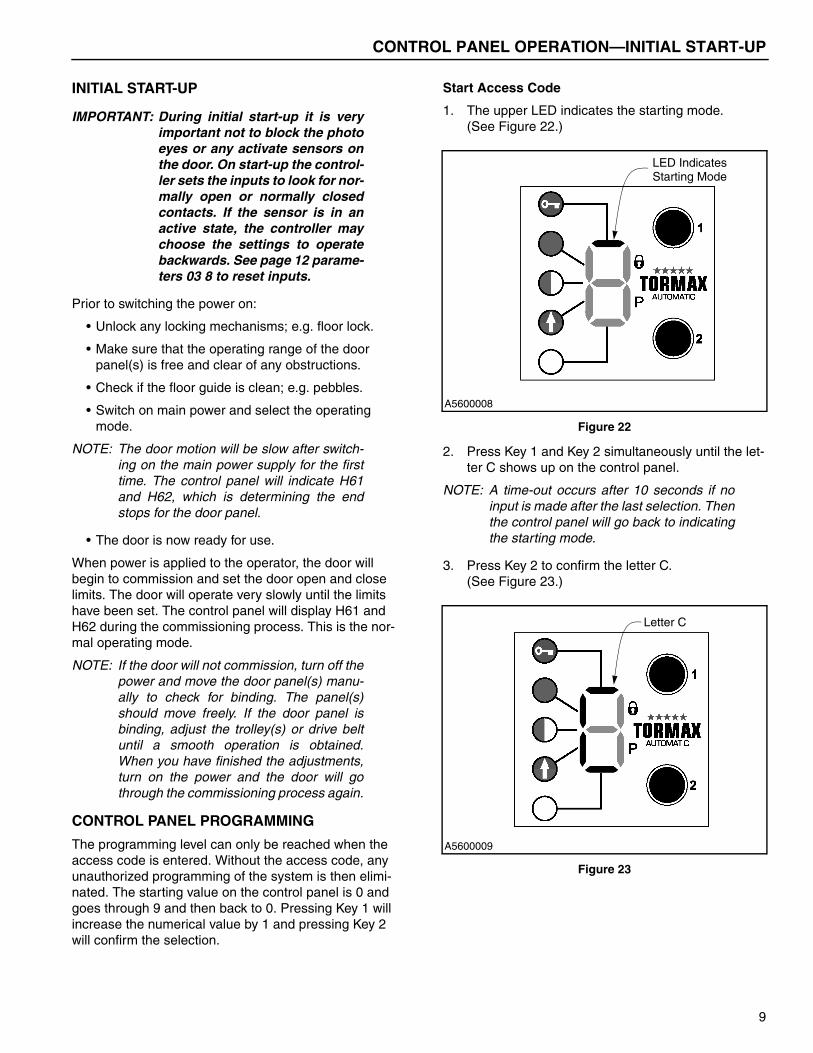
1. The upper LED indicates the starting mode. (See Figure 22.)
Figure 22
2. Press Key 1 and Key 2 simultaneously until the let-ter C shows up on the control panel.
NOTE: A time-out occurs after 10 seconds if noinput is made after the last selection. Thenthe control panel will go back to indicatingthe starting mode.
3. Press Key 2 to confirm the letter C.(See Figure 23.)
Figure 23
A5600008
LED IndicatesStarting Mode
A5600009
Letter C
9

CONTROL PANEL OPERATION—CONTROL PANEL PROGRAMMING
Entering Access Code
1. After pressing Key 2 to confirm the letter C, a zero appears for entering the access code. (See Figure 24.)
NOTE: A time-out occurs after 10 seconds if noinput is made after the last selection. Thenthe control panel will go back to indicatingthe starting mode.
Figure 24
2. Enter access code 111:
a. Press Key 1 until number 1 is selected.
b. Press Key 2 to confirm the first digit.
c. Press Key 1 until number 1 is selected.
d. Press Key 2 to confirm the second digit.
e. Press Key 1 until number 1 is selected.
f. Press Key 2 to confirm the third digit.
Start Programming Level
1. After the access code has been entered, the letter P appears on the control panel.
2. Confirm by pressing Key 2 and now the system is ready for programming.
Figure 25
Entering Parameter Code
1. Zero appears as first digit of code. Select first code digit using Key 1.
2. Confirm digit with Key 2.
3. Select and confirm the second and third code digits in the same manner as the first digit code.
NOTE: After the second code digit has been con-firmed, the flashing display shows the setvalue of the parameter. If this or the cor-rected value is confirmed, the value issaved. This is indicated by a rapidly flash-ing display during the first second.
By quickly pressing both keys simultane-ously an immediate return to the display ofthe operating mode can be effected.
Figure 26
A5600011
Number 0
A5600010
Letter P
A5600011
Number 0
10

CONTROL PANEL OPERATION—CONTROL PANEL PROGRAMMING
Time-Out
If no entry is made during 10 seconds from the last input, P is shown again.
If P is not confirmed during the next 10 seconds with Key 2, the control panel returns to the indication of the starting mode (see Figure 22). During the next 10 min-utes, pressing both keys simultaneously will cause a direct change to programming level P.
Exiting Programming Level
After a time-out of 10 minutes, the programming level will be automatically protected by the access code. The access code must be re-entered as described in “Start Access Code” on page 9 to return to the programming level.
PROGRAMMING EXAMPLE
Accessing programming level:
Figure 27
The system is now in programming mode. Enter the code of the parameter to be maintained. If the letter P disappears after 10 seconds, you can change back into programming mode P by simultaneously pressing Keys 1 and 2 within 10 minutes.
Figure 28
A5600012
Press Keys 1 and 2 at the same time:
Press Key 2 to confirm selection...............
Select first digit 1 with Key 1.....................
Confirm with Key 2....................................
Select second digit 1 with Key 1...............
Confirm with Key 2....................................
Select third digit 1 with Key 1....................
Confirm with Key 2....................................
Access to program level confirmed...........
Display
A5600014
Press Keys 1 and 2 at the same time:
Press Key 2 to confirm selection...............
Select first digit 1 with Key 1.....................
Confirm with Key 2....................................
Select second digit 1 with Key 1...............
Confirm with Key 2....................................
Select third digit 1 with Key 1....................
Confirm with Key 2....................................
Access to program level confirmed...........
Display
}The Display FlashesDuring This Segment
11
PROGRAMMING CODES—CONTROL PANEL PROGRAMMING
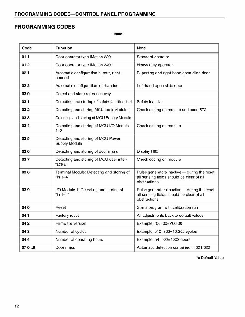
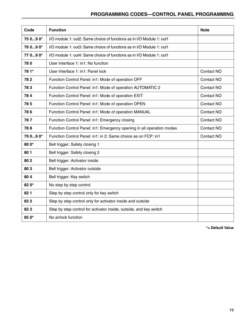
PROGRAMMING CODESTable 1
*= Default Value
Code Function Note
01 1 Door operator type iMotion 2301 Standard operator
01 2 Door operator type iMotion 2401 Heavy duty operator
02 1 Automatic configuration bi-part, right- handed
Bi-parting and right-hand open slide door
02 2 Automatic configuration left-handed Left-hand open slide door
03 0 Detect and store reference way
03 1 Detecting and storing of safety facilities 1–4 Safety inactive
03 2 Detecting and storing MCU Lock Module 1 Check coding on module and code 572
03 3 Detecting and storing of MCU Battery Module
03 4 Detecting and storing of MCU I/O Module 1+2
Check coding on module
03 5 Detecting and storing of MCU Power Supply Module
03 6 Detecting and storing of door mass Display H65
03 7 Detecting and storing of MCU user inter-face 2
Check coding on module
03 8 Terminal Module: Detecting and storing of “in 1–4”
Pulse generators inactive — during the reset, all sensing fields should be clear of all obstructions
03 9 I/O Module 1: Detecting and storing of “in 1–4”
Pulse generators inactive — during the reset, all sensing fields should be clear of all obstructions
04 0 Reset Starts program with calibration run
04 1 Factory reset All adjustments back to default values
04 2 Firmware version Example: r06_00=V06.00
04 3 Number of cycles Example: c10_302=10,302 cycles
04 4 Number of operating hours Example: h4_002=4002 hours
07 0...9 Door mass Automatic detection contained in 021/022
12
PROGRAMMING CODES—CONTROL PANEL PROGRAMMING
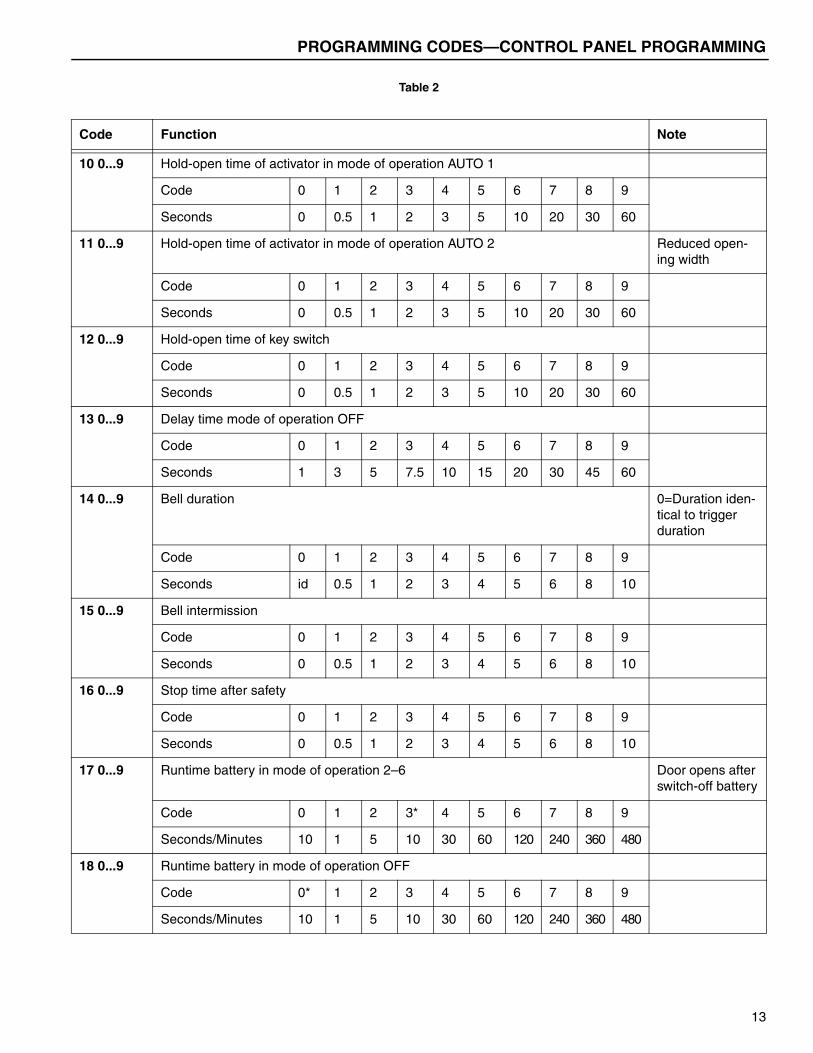
Table 2
Code Function Note
10 0...9 Hold-open time of activator in mode of operation AUTO 1
Code 0 1 2 3 4 5 6 7 8 9
Seconds 0 0.5 1 2 3 5 10 20 30 60
11 0...9 Hold-open time of activator in mode of operation AUTO 2 Reduced open-ing width
Code 0 1 2 3 4 5 6 7 8 9
Seconds 0 0.5 1 2 3 5 10 20 30 60
12 0...9 Hold-open time of key switch
Code 0 1 2 3 4 5 6 7 8 9
Seconds 0 0.5 1 2 3 5 10 20 30 60
13 0...9 Delay time mode of operation OFF
Code 0 1 2 3 4 5 6 7 8 9
Seconds 1 3 5 7.5 10 15 20 30 45 60
14 0...9 Bell duration 0=Duration iden-tical to trigger duration
Code 0 1 2 3 4 5 6 7 8 9
Seconds id 0.5 1 2 3 4 5 6 8 10
15 0...9 Bell intermission
Code 0 1 2 3 4 5 6 7 8 9
Seconds 0 0.5 1 2 3 4 5 6 8 10
16 0...9 Stop time after safety
Code 0 1 2 3 4 5 6 7 8 9
Seconds 0 0.5 1 2 3 4 5 6 8 10
17 0...9 Runtime battery in mode of operation 2–6 Door opens after switch-off battery
Code 0 1 2 3* 4 5 6 7 8 9
Seconds/Minutes 10 1 5 10 30 60 120 240 360 480
18 0...9 Runtime battery in mode of operation OFF
Code 0* 1 2 3 4 5 6 7 8 9
Seconds/Minutes 10 1 5 10 30 60 120 240 360 480
13

PROGRAMMING CODES—CONTROL PANEL PROGRAMMING
20 0...9 Speed opening
Code 0 1 2 3 4 5 6 7 8 9
Inches/Second 3.93 7.87 11.8 15.7 19.6 23.6 27.5 31.5 35.4 39.3
21 0...9 Speed closing
Code 0 1 2 3 4 5 6 7 8 9
Inches/Second 3.15 6.3 9.45 12.6 15.7 18.9 22.0 25.2 28.3 31.5
22 0...9 Homing-in-speed close, minimal
Code 0* 1 2 3 4 5 6 7 8 9
Millimeters/Second 15 16 18 21 25 30 36 43 51 60
26 0...9 2* Breaking distance opening 9=max
28 0...9 4* Breaking distance opening 9=max
30 0...9 Motor force opening Net force on door edge
Code 0 1 2 3 4 5 6 7 8 9
% 10 20 30 40 50 60 70 80 90 100
31 0...9 Motor force closing Net force on door edge
Code 0 1 2 3 4 5* 6 7 8 9
% 10 20 30 40 50 60 70 80 90 100
33 0...9 Force closed position Net force on door edge>reduce if H73 after 10s!
Code 0 1 2 3 4 5 6 7 8 9
N 10 20 30 40 50 60 70 80 90 100
35 0...9 5* Reversing sensitivity opening 9=max
36 0...9 5* Reversing sensitivity opening 9=max
41 0...9 Reduced opening width
Code 0 1 2 3 4 5 6 7 8 9
% 10 20 30 40 50 60 70 80 90 100
51 0* Operating mode return to last setting on Function Control Panel After terminal operating mode
51 1...6 Operating mode return to mode of operation After terminal operating mode
Code 1 2 3 4 5 6
Mode of operation OFF AUT1 AUT2 EXIT OPEN MANUAL
Code Function Note
14
PROGRAMMING CODES—CONTROL PANEL PROGRAMMING
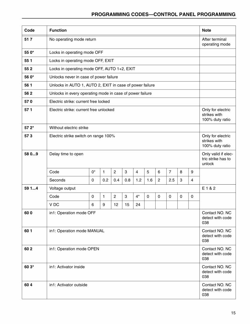
51 7 No operating mode return After terminal operating mode
55 0* Locks in operating mode OFF
55 1 Locks in operating mode OFF, EXIT
55 2 Locks in operating mode OFF, AUTO 1+2, EXIT
56 0* Unlocks never in case of power failure
56 1 Unlocks in AUTO 1, AUTO 2, EXIT in case of power failure
56 2 Unlocks in every operating mode in case of power failure
57 0 Electric strike: current free locked
57 1 Electric strike: current free unlocked Only for electric strikes with 100% duty ratio
57 2* Without electric strike
57 3 Electric strike switch on range 100% Only for electric strikes with 100% duty ratio
58 0...9 Delay time to open Only valid if elec-tric strike has to unlock
Code 0* 1 2 3 4 5 6 7 8 9
Seconds 0 0.2 0.4 0.8 1.2 1.6 2 2.5 3 4
59 1...4 Voltage output E 1 & 2
Code 0 1 2 3 4* 0 0 0 0 0
V DC 6 9 12 15 24
60 0 in1: Operation mode OFF Contact NO. NC detect with code 038
60 1 in1: Operation mode MANUAL Contact NO. NC detect with code 038
60 2 in1: Operation mode OPEN Contact NO. NC detect with code 038
60 3* in1: Activator inside Contact NO. NC detect with code 038
60 4 in1: Activator outside Contact NO. NC detect with code 038
Code Function Note
15

PROGRAMMING CODES—CONTROL PANEL PROGRAMMING
60 5 in1: Key switch Contact NO. NC detect with code 038
60 6 in1: Emergency open except in OFF Contact NO. NC detect with code 038
60 7 in1: Emergency open in all modes of operation Contact NO. NC detect with code 038
60 8 in1: Emergency close (with locking) Contact NO. NC detect with code 038
60 9 in1: Operation mode EXIT Contact NO. NC detect with code 038
61 0...9 4* in2: Same choice of functions as on “in 1” Contact NO. NC detect with code 038
62 0...9 5* in3: Same choice of functions as on “in 1” Contact NO. NC detect with code 038
63 0...9 0* in4: Same choice of functions as on “in 1” Contact NO. NC detect with code 038
64 0 sf1: Safety opening 1 with stop function Type of connec-tion detect with code 031
64 1 sf1: Safety opening 1 with creeping function Type of connec-tion detect with code 031
64 2* sf1: Safety closing 1 with reversing function Type of connec-tion detect with code 031
64 3 sf1: Safety closing 1 with creeping function Type of connec-tion detect with code 031
64 4 sf1: Safety swing area Type of connec-tion detect with code 031
64 5 sf1: Safety stop Type of connec-tion detect with code 031
64 6 sf1: Emergency opening except in OFF Type of connec-tion detect with code 031
Code Function Note
16

PROGRAMMING CODES—CONTROL PANEL PROGRAMMING
64 7 sf1: Emergency opening in all modes of operation Type of connec-tion detect with code 031
64 8 sf1: Emergency closing (with locking) Type of connec-tion detect with code 031
64 9 sf1: Mode of op. MANUAL/Break out Type of connec-tion detect with code 031
64 A sf1: Safety opening 2 with stop function Type of connec-tion detect with code 031
64 b sf1: Safety opening 2 with creeping function Type of connec-tion detect with code 031
64 C sf1: Safety closing 2 with reverse function Type of connec-tion detect with code 031
64 d sf1: Safety closing 2 with creeping function Type of connec-tion detect with code 031
65 0...d C* sf2: Same choice of functions as on “sf1” Type of connec-tion detect with code 031
66 0...d 0* sf3: Same choice of functions as on “sf1” Type of connec-tion detect with code 031
67 0...d A* sf4: Same choice of functions as on “sf1” Type of connec-tion detect with code 031
68 0 out1: Message “door closed”
68 1 out1: Message “door closed and locked”
68 2 out1: Message “door open”
68 3 out1: Message “general error”
68 4* out1: Bell
68 5 out1: Message “mode of operation OFF”
68 7 out1: Battery in service
68 9 out1: Message “door opening or open” Function visible after 1 door opening cycle
69 0...9 0* out2: Same choice of functions as on “out1”
Code Function Note
17

PROGRAMMING CODES—CONTROL PANEL PROGRAMMING
70 0* I/O Module 1: in1: No function Contact NO. NC detect with code 039.
70 1 I/O Module 1: in1: Operation mode OFF Contact NO. NC detect with code 039.
70 2 I/O Module 1: in1: Operation mode AUTOMATIC 1 Contact NO. NC detect with code 039.
70 3 I/O Module 1: in1: Operation mode AUTOMATIC 2 Contact NO. NC detect with code 039.
70 4 I/O Module 1: in1: Operation mode EXIT Contact NO. NC detect with code 039.
70 5 I/O Module 1: in1: Operation mode OPEN Contact NO. NC detect with code 039.
70 6 I/O Module 1: in1: Operation mode MANUAL Contact NO. NC detect with code 039.
70 7 I/O Module 1: in1: Inhibit switch Contact NO. NC detect with code 039.
71 0...7 0* I/O Module 1: in2: Same choice of functions as on I/O Module 1: in1 Contact NO. NC detect with code 039.
72 0...7 0* I/O Module 1: in3: Same choice of functions as on I/O Module 1: in1 Contact NO. NC detect with code 039.
73 0...7 0* I/O Module 1: in4: Same choice of functions as on I/O module 1: in1 Contact NO. NC detect with code 039.
74 0* I/O Module 1: out1: No function
74 1 I/O Module 1: out1: Mode of operation OFF
74 2 I/O Module 1: out1: Mode of operation AUTOMATIC 1
74 3 I/O Module 1: out1: Mode of operation AUTOMATIC 2
74 4 I/O Module 1: out1: Mode of operation EXIT
74 5 I/O Module 1: out1: Mode of operation OPEN
74 6 I/O Module 1: out1: Mode of operation MANUAL
74 7 I/O Module 1: out1: Door opens
Code Function Note
18
PROGRAMMING CODES—CONTROL PANEL PROGRAMMING
*= Default Value
75 0...9 0* I/O module 1: out2: Same choice of functions as in I/O Module 1: out1
76 0...9 0* I/O module 1: out3: Same choice of functions as in I/O Module 1: out1
77 0...9 0* I/O module 1: out4: Same choice of functions as in I/O Module 1: out1
78 0 User Interface 1: in1: No function
78 1* User Interface 1: in1: Panel lock Contact NO
78 2 Function Control Panel: in1: Mode of operation OFF Contact NO
78 3 Function Control Panel: in1: Mode of operation AUTOMATIC 2 Contact NO
78 4 Function Control Panel: in1: Mode of operation EXIT Contact NO
78 5 Function Control Panel: in1: Mode of operation OPEN Contact NO
78 6 Function Control Panel: in1: Mode of operation MANUAL Contact NO
78 7 Function Control Panel: in1: Emergency closing Contact NO
78 8 Function Control Panel: in1: Emergency opening in all operation modes Contact NO
79 0...9 0* Function Control Panel: in1: in 2: Same choice as on FCP: in1 Contact NO
80 0* Bell trigger: Safety closing 1
80 1 Bell trigger: Safety closing 2
80 2 Bell trigger: Activator inside
80 3 Bell trigger: Activator outside
80 4 Bell trigger: Key switch
82 0* No step by step control
82 1 Step by step control only for key switch
82 2 Step by step control only for activator inside and outside
82 3 Step by step control for activator inside, outside, and key switch
85 0* No airlock function
Code Function Note
19

TROUBLESHOOTING—DISPLAY AND RESET CONTROL PANEL
TROUBLESHOOTINGError messages on the control panel are the result of sporadic door malfunctions. Error messages appear on the control panel as a flashing E or H followed by two numerical figures. When the letter H is displayed on the control panel, there is information pertaining to erratic door operations. The door can continue its service but it will require maintenance. When the letter E is displayed on the control panel, there is a fault and the system has stopped operating. It will require immediate repair.
DISPLAY AND RESET CONTROL PANEL
1. Press Key 1 to process the fault(s) listed on the con-trol panel.
2. Press Key 2 to reset the error message or push for 5 seconds for software reset.
Figure 29
Control Panel Fault Reset — Power Supply
If the instructions above do not clear the error mes-sages, turn off the main power supply to the system for a minimum of 10 seconds and reapply power. See “INI-TIAL START-UP” on page 9 when power is first applied to the door.
If this doesn’t clear or fix the malfunction, please contact your Rytec representative or call the Rytec Customer Support Department at 800-628-1909. Always refer to the serial number of the door that your control system is connected to when calling the representative or Cus-tomer Support. Refer to the installation or owner’s man-ual provided with your door for the location of the serial number plate.
A5600001
Key 1
Key 2
20
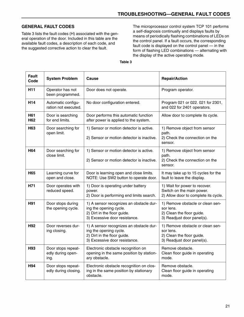
TROUBLESHOOTING—GENERAL FAULT CODES
GENERAL FAULT CODES
Table 3 lists the fault codes (H) associated with the gen-eral operation of the door. Included in this table are the available fault codes, a description of each code, and the suggested corrective action to clear the fault.
The microprocessor control system TCP 101 performs a self-diagnosis continually and displays faults by means of periodically flashing combinations of LEDs on the control panel. If a fault occurs, the corresponding fault code is displayed on the control panel — in the form of flashing LED combinations — alternating with the display of the active operating mode.
Table 3
Fault Code
System Problem Cause Repair/Action
H11 Operator has not been programmed.
Door does not operate. Program operator.
H14 Automatic configu-ration not executed.
No door configuration entered. Program 021 or 022. 021 for 2301, and 022 for 2401 operators.
H61H62
Door is searching for end limits.
Door performs this automatic function after power is applied to the system.
Allow door to complete its cycle.
H63 Door searching for open limit.
1) Sensor or motion detector is active.
2) Sensor or motion detector is inactive.
1) Remove object from sensor path.2) Check the connection on the sensor.
H64 Door searching for close limit.
1) Sensor or motion detector is active.
2) Sensor or motion detector is inactive.
1) Remove object from sensor path.2) Check the connection on the sensor.
H65 Learning curve for open and close.
Door is learning open and close limits. NOTE: Use SW2 button to operate door.
It may take up to 15 cycles for the fault to leave the display.
H71 Door operates with reduced speed.
1) Door is operating under battery power.2) Door is performing end limits search.
1) Wait for power to recover.Switch on the main power.2) Allow door to complete its cycle.
H91 Door stops during the opening cycle.
1) A sensor recognizes an obstacle dur-ing the opening cycle.2) Dirt in the floor guide.3) Excessive door resistance.
1) Remove obstacle or clean sen-sor lens.2) Clean the floor guide.3) Readjust door panel(s).
H92 Door reverses dur-ing closing.
1) A sensor recognizes an obstacle dur-ing the opening cycle.2) Dirt in the floor guide.3) Excessive door resistance.
1) Remove obstacle or clean sen-sor lens.2) Clean the floor guide.3) Readjust door panel(s).
H93 Door stops repeat-edly during open-ing.
Electronic obstacle recognition on opening in the same position by station-ary obstacle.
Remove obstacle. Clean floor guide in operating mode.
H94 Door stops repeat-edly during closing.
Electronic obstacle recognition on clos-ing in the same position by stationary obstacle.
Remove obstacle. Clean floor guide in operating mode.
21
TROUBLESHOOTING—GENERAL FAULT CODES
Table 4 lists the fault codes (E) associated with the gen-eral operation of the door. Included in this table are the available fault codes, a description of each code, and the suggested corrective action to clear the fault.
Table 4
Fault Code
System Problem Cause Repair/Action
– Door remains closed.
1) Operating mode OFF or P has been selected.2) Operating mode EXIT has been selected.
1) Select operating mode AUTO-MATIC 1 or AUTOMATIC 2.2) Door will only open from one side; find alternate exit or entrance.
– Door remains open. Operating mode OPEN or P has been selected.
Select an operating mode.
– Door hits a person or object.
Inadequate adjustment(s) or dirty sen-sors.
Remove door from service until repairs or adjustments are done.
E11 Door does not lock in OFF.
1) Lock is jammed.
2) Lock is defective.
1) With the door closed, press against the door panel for a few seconds.2) Replace lock.
E11 Door does not open after changing from OFF to AUTO-MATIC. Lock makes switching noise.
1) Lock is jammed.
2) Lock is defective.
1) With the door closed, press against the door panel for a few seconds.2) Replace lock.
E11 Door does not open in OFF through the key switch. Lock makes switching noise.
1) Lock is jammed.
2) Lock is defective.
1) With the door closed, press against the door panel for a few seconds.2) Replace lock.
E31 Door remains closed.
1) The safety sensor in the opening direction is permanently active (>1 min.).
2) The safety sensor in the opening direction is defective.
1) Remove the object(s) within the range of the sensor. Clean lens of the sensor.2) First, clean lens of the sensor and retry door operation. Second, replace sensor.
E32 Door remains open. 1) The safety sensor in the closing direc-tion is permanently active (>1 min.).
2) The safety sensor in the closing direction is defective.
1) Remove the object(s) within the range of the sensor. Clean lens of the sensor.2) First, clean lens of the sensor and retry door operation. Second, replace sensor.
E33 Door will not open or close.
1) The safety sensor in the opening direction is permanently active (>1 min.).
2) The safety sensor in the opening direction is defective.
1) Remove the object(s) within the range of the sensor. Clean lens of the sensor.2) First, clean lens of the sensor and retry door operation. Second, replace sensor.
22

TROUBLESHOOTING—GENERAL FAULT CODES
E34 Door will not open or close.
The safety facility stop is permanently active (> 1 min.) or defective.
Remove the object(s) within the range of the sensor.
E41 Door remains open. The inside door activator is active (>1 min.).
Clean and readjust sensor as needed.
E42 Door remains open. The outside door activator is active (>1 min.).
Clean and readjust sensor as needed.
E43 Door remains open. 1) Key switch is active (>1 min.).2) Key switch is defective.
1) Reset key switch.2) Replace key switch.
E5.. Door stops. 1) There is an obstacle in the path of the door panel.2) Excessive door resistance.3) System may have a glitch or malfunc-tion.
1) Remove obstacle from the path of the door panel.2) Adjust the door panel(s).3) Perform a system reset.
E61E62
Door stops. Power supply is overloaded or voltage is too low.
Have a electrician check out the power supply and connections.
E64E65
Door stops. The drive/control system is overheated. Wait for the automatic reset after cooling down.Door panel may need adjustment.
E8.. Door remains open. Control unit safety power is off. Perform a system reset.
Fault Code
System Problem Cause Repair/Action
23

TROUBLESHOOTING—TROUBLESHOOTING WITH LEDS
TROUBLESHOOTING
TROUBLESHOOTING WITH LEDS
If a problem occurs with the control system or the door, the controller is configured with various light-emitting diodes (LEDs) that can be helpful when troubleshooting the problem. The LEDs are grouped in various functions and indicators as detailed below with interpretation of each group of LEDs.
Battery Module
1. Battery Module
2. Batteries (12 Volt)
3. Battery Cable
4. Fuse
5. LEDs
6. Inputs (Terminals)
7. Power Cable
8. Mounting Bracket
Figure 30
Functions
As long as the battery module is in standby operation (normal operation) and main power is applied to the control system and battery module is connected, the door operator is supplied directly from main power sup-ply and the batteries are charged (LED 1 is illuminated).
Periodic Tests
An automatic battery test occurs once a week, providing the system was programmed accordingly by the installer or owner. However, the test is only activated through an opening command. On completion of the test, the door is automatically put back into normal oper-ation (LEDs 1 and 2 are illuminated).
Power Failure/Voltage Variations
In case of power failure or variations in voltage, the bat-tery module switches automatically without interruption to battery operation (LED 2 is illuminated).
Power Recovery
When power is restored, the system switches automat-ically back to normal operation and starts recharging the batteries.
NOTE: If the batteries have been completely dis-charged, it will take several hours to fullycharge.
Programmable Functions
The operating actions of the battery module can be pro-grammed by the installer or owner. Depending on the programming, the door will operate on battery power as follows:
a. The door continues to operate in the power sav-ing mode (standard setting). The door operates on reduced speed and less energy. The sus-tained maximum number of opening cycles is dependent on a number of factors: door weight, sensor load, and the current capacity and charge of the batteries.
b. The door panels are moved into a selected posi-tion and then the system is switched to operating mode OFF. This will make the sensors inactive.
A5600015Battery Module
1 2
7 6 5 4 3 8
24

TROUBLESHOOTING—TROUBLESHOOTING WITH LEDS
LED Display
The LED (Light Emitting Diode) display is built into the battery module. The display will define the illuminated LEDs and assist in troubleshooting door symptoms.
• Voltage from the main power supply is off. (See Figure 31.)
NOTE: Batteries are being charged.
Figure 31
• The main voltage is low or the door is experiencing reduced performance. (See Figure 32.)
NOTE: Batteries are not being charged.
Figure 32
• The main voltage is low or the door is experiencing reduced performance. (See Figure 33.)
NOTE: The door is under battery operation in sup-port of door operation.
Figure 33
• Power provided by main power supply. (See Figure 34.)
NOTE: Battery test is being performed.
Figure 34
A5600016
A5600017
A5600018
A5600019
25
TROUBLESHOOTING—TROUBLESHOOTING WITH LEDS
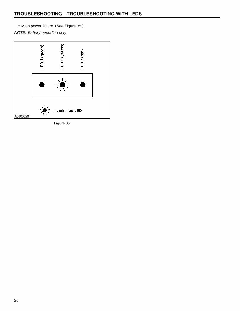
• Main power failure. (See Figure 35.)
NOTE: Battery operation only.
Figure 35
A5600020
26
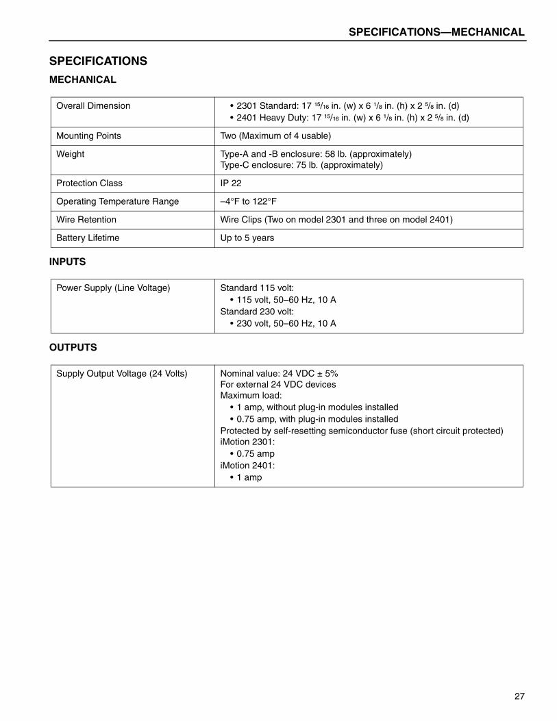
SPECIFICATIONS—MECHANICAL
SPECIFICATIONS
MECHANICAL
INPUTS
OUTPUTS
Overall Dimension • 2301 Standard: 17 ¹⁵/₁₆ in. (w) x 6 ¹/₈ in. (h) x 2 ⁵/₈ in. (d)• 2401 Heavy Duty: 17 ¹⁵/₁₆ in. (w) x 6 ¹/₈ in. (h) x 2 ⁵/₈ in. (d)
Mounting Points Two (Maximum of 4 usable)
Weight Type-A and -B enclosure: 58 lb. (approximately)Type-C enclosure: 75 lb. (approximately)
Protection Class IP 22
Operating Temperature Range –4°F to 122°F
Wire Retention Wire Clips (Two on model 2301 and three on model 2401)
Battery Lifetime Up to 5 years
Power Supply (Line Voltage) Standard 115 volt:• 115 volt, 50–60 Hz, 10 A
Standard 230 volt:• 230 volt, 50–60 Hz, 10 A
Supply Output Voltage (24 Volts) Nominal value: 24 VDC ± 5%For external 24 VDC devicesMaximum load:
• 1 amp, without plug-in modules installed• 0.75 amp, with plug-in modules installed
Protected by self-resetting semiconductor fuse (short circuit protected)iMotion 2301:
• 0.75 ampiMotion 2401:
• 1 amp
27
SPECIFICATIONS—ABBREVIATIONS
ABBREVIATIONS
Table 5 lists the abbreviation of each unit of measure-ment referenced throughout the control system program menu and this manual.
Table 5
Unit Abbreviation
Celsius °C
Counter Cnt
Current (Ampere) A
Cycles Cyc
Digits Dig
Fahrenheit °F
Hertz (Frequency) Hz
Increments Inc
Milliseconds Ms
Minute Min
Number #
Percentage %
Seconds Sec
Voltage (Volt) V
28
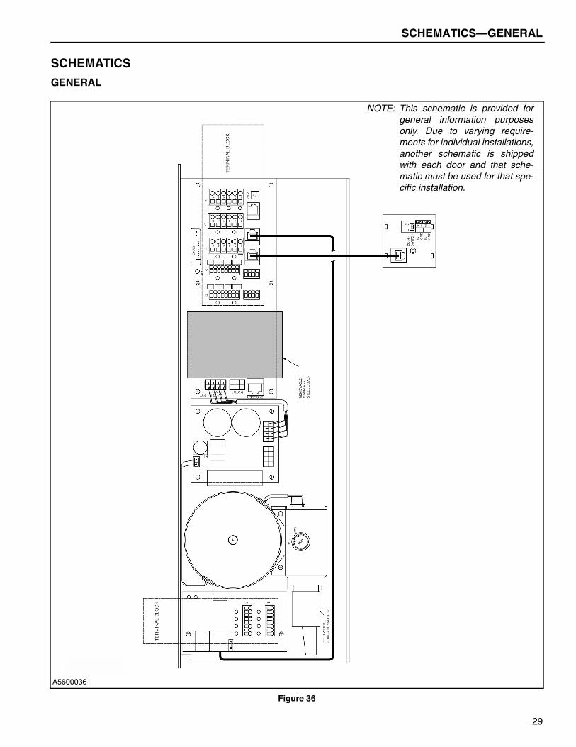
SCHEMATICS—GENERAL
SCHEMATICS
GENERAL
Figure 36
A5600036
NOTE: This schematic is provided forgeneral information purposesonly. Due to varying require-ments for individual installations,another schematic is shippedwith each door and that sche-matic must be used for that spe-cific installation.
29

SCHEMATICS—GENERAL (SHEET 2)
GENERAL (SHEET 2)
Figure 37
A5600037
NOTE: This schematic is provided forgeneral information purposesonly. Due to varying require-ments for individual installations,another schematic is shippedwith each door and that sche-matic must be used for that spe-cific installation.
30

NOTES
31
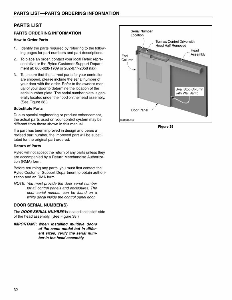
PARTS LIST—PARTS ORDERING INFORMATION
PARTS LIST
PARTS ORDERING INFORMATION
How to Order Parts
1. Identify the parts required by referring to the follow-ing pages for part numbers and part descriptions.
2. To place an order, contact your local Rytec repre-sentative or the Rytec Customer Support Depart-ment at: 800-628-1909 or 262-677-2058 (fax).
3. To ensure that the correct parts for your controller are shipped, please include the serial number of your door with the order. Refer to the owner’s man-ual of your door to determine the location of the serial number plate. The serial number plate is gen-erally located under the hood on the head assembly. (See Figure 38.)
Substitute Parts
Due to special engineering or product enhancement, the actual parts used on your control system may be different from those shown in this manual.
If a part has been improved in design and bears a revised part number, the improved part will be substi-tuted for the original part ordered.
Return of Parts
Rytec will not accept the return of any parts unless they are accompanied by a Return Merchandise Authoriza-tion (RMA) form.
Before returning any parts, you must first contact the Rytec Customer Support Department to obtain authori-zation and an RMA form.
NOTE: You must provide the door serial numberfor all control panels and enclosures. Thedoor serial number can be found on awhite decal inside the control panel door.
DOOR SERIAL NUMBER(S)
The DOOR SERIAL NUMBER is located on the left side of the head assembly. (See Figure 38.)
IMPORTANT: When installing multiple doorsof the same model but in differ-ent sizes, verify the serial num-ber in the head assembly.
Figure 38
Serial Number
A3100224
End
HeadAssembly
Seal Stop Column
Column
Tormax Control Drive withHood Half Removed
Door Panel
with Wall Jamb
Location
32
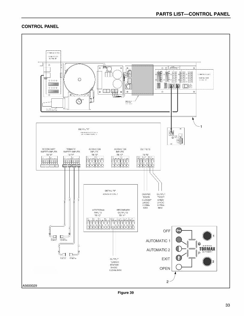
PARTS LIST—CONTROL PANEL
CONTROL PANEL
Figure 39
A5600029
1
2
33
PARTS LIST—CONTROL PANEL
ITEM QTY. PART # DESCRIPTION
1 1 1120212-0 iMotion 2301 Drive1120213-0 iMotion 2401 Drive
2 1 1120273-0 Control Plate, iMotion3 1 1120291-0 Cable, iMotion (not shown)4 1 1120215-0 Solenoid Lock (optional)
(not shown)5 1 1120274-0 I/O Module (optional) (not
shown)6 1 1120165-0 Photoeyes (includes one
set of transmitter and receiver) (not shown)
34


![TORMAX TX9000 PARTS CATALOG v103 - 2 - ABsupply.net TX9000Motion_Catalog.pdf · tormax technologies 11803 starcrest dr san antonio, tx 78247 (210) 494-3551 (210) 494-5930 [fax] v1.02](https://img.pdfslide.us/doc/110x75/5ae0bcab7f8b9a5a668dfc92/tormax-tx9000-parts-catalog-v103-2-tx9000motioncatalogpdftormax-technologies.jpg)