Embed Size (px)
Citation preview

REMOTETASK™ OPERATION AND MAINTENANCE MANUAL, VERSION 1.2
1
e
REMOTETASK™ Operation and Maintenance Manual V.1.2

REMOTETASK™ OPERATION AND MAINTENANCE MANUAL, VERSION 1.2
2
Assignment of Liability
WARNING: DO NOT OPERATE UNTIL USER MANUAL IS REVIEWED AND UNDERSTOOD.
PRODUCT USE IS SUBJECT TO STRICT TERMS AND CONDITIONS. SEE TERMS AND
CONDITIONS DOCUMENT FOR ADDITIONAL USE RESTRICTIONS. OPERATING
PRODUCT IN VIOLATION OF USER RESTRICTIONS COULD RESULT IN PRODUCT
MALFUNCTION, PROPERTY DAMAGE, AND PERSONAL INJURY INCLUDING DEATH.
NOTICE: USER ASSUMES ALL RISKS ASSOCIATED WITH POSSESSION OR USE OF
PRODUCT AND RELATED SYSTEMS. USER AGREES TO INDEMNIFY, DEFEND AND
HOLD HARMLESS TORC ROBOTICS, Inc. (“TORC®”) FROM ANY DAMAGES ARISING OUT
OF POSSESSION OR USE OF PRODUCT AND RELATED SYSTEMS. TORC IS NOT LIABLE
FOR ANY DAMAGES OF ANY KIND.
NOTICE: SEE TERMS AND CONDITIONS FOR ALL TERMS APPLICABLE TO USE OF THE
PRODUCT OR RELATED SOFTWARE.
Copyright © 2016 TORC Robotics, Inc. All Rights Reserved. All information contained in this
manual is believed to be accurate at the time of printing; however, TORC Robotics, Inc.
reserves the right to make modifications to the specifications and operation of this product
without obligation to notify any person or entity of such revision.
TORC® and SafeStop® are trademarks of TORC Robotics, Inc.

REMOTETASK™ OPERATION AND MAINTENANCE MANUAL, VERSION 1.2
3
Foreword
This manual provides safety information, operator instructions, and maintenance instructions for
the RemoteTask™ Remote Control System that can be installed in most CAT D-Series Skid
Steer Loader (SSL), Multi Terrain Loader (MTL), and Compact Track Loader (CTL). This
manual is to be used in addition to the documentation and the Operation and Maintenance
Manual that is provided with the machine.
This manual should be stored in the operator’s compartment in the literature holder or seat back
literature storage area. Keep this manual with the machine that is installed with the
RemoteTask™ system.
Some photographs or illustrations in this publication show details or attachments that can be
different from your machine. Guards and covers might have been removed for illustrative
purposes.

REMOTETASK™ OPERATION AND MAINTENANCE MANUAL, VERSION 1.2
4
Table of Contents
Assignment of Liability 2 Foreword 3 Table of Contents 4 Important Safety Information 6
1 - GENERAL INFORMATION 7
Product Overview 7 Intended Use 7 Remote Control Safety 8
Additional Safety Messages 9 Effects on System Operation 13
RF Interference 13 Environmental 13 Installation 13
2 - COMPONENTS OVERVIEW 14
RemoteTask™ Controller 14 RemoteTask
TM Machine Interface 15
3 - OPERATOR FEEDBACK 16
Warning Feedback 17 Status Feedback 20
LED Indicators 20 Multilevel LED Indicators 22
4 - OPERATOR CONTROLS 24
Key Switch Controls 24 Machine Remote Enable Interface 24 Controller Key Switch 25
Remote Operation Controls 26 Remote Knob Controls Detail 29 Remote Joystick Detail - Left Hand 30 Remote Joystick Detail - Right Hand 31 Remote Work Tools Detail 32
5 - SAFETY FEATURES 33
Emergency Stop 33 In Cab Override 33 Degraded Communication Link 33 Man-Down Feature 34 Implement Lowering with Engine Stopped 34
6 - REMOTE OPERATION 35
Transition Machine to Remote Operation 36 Remote Startup Procedure 37 Remote Shutdown Procedure 38 Return Machine to Manual Operation 39

REMOTETASK™ OPERATION AND MAINTENANCE MANUAL, VERSION 1.2
5
Battery Replacement and Charging 40
7 - SYSTEM CONFIGURATION 41
Pairing Controller with Machine 41 Shoulder Harness Attachment 42
Front Configuration 42 Right Side Configuration 43 Left Side Configuration 43
8 - MAINTENANCE 44
General Care 44 Maintenance Schedule 45 RemoteTask Parts List 45
9 - TROUBLESHOOTING 46
General Troubleshooting 46 Troubleshooting Issues 48
No Link between RemoteTask™ Controller and Machine 48 Machine engine will not start remotely 48 Linked machine will not operate 49 Work tool will not operate 49 Machine stops suddenly during operation 49 Engine RPM increases spontaneously or will not decrease via Engine Speed Control Knob 50 AUX 8 Control will not disengage remotely 50 Red “Service” light on Remote Enable Interface is illuminated. 50 Remote Controller does not power off immediately. 51
10 - SPECIFICATIONS 52
11 - FFC COMPLIANCE 53
12 - LIMITED WARRANTY 53

REMOTETASK™ OPERATION AND MAINTENANCE MANUAL, VERSION 1.2
6
Important Safety Information
Failure to observe the outlined safety measures regarding operation, maintenance, and repair is
the most common cause of accidents that involve product operation. It is important to heed all
safety precautions and warnings provided in this manual and on the product.
Do not operate the machine unless you have read and understand the instructions and
warnings in the Operation and Maintenance manual. The list of procedures and hazards
identified by WARNING and NOTICE labels is not all inclusive. TORC cannot anticipate every
possible circumstance that might involve a potential hazard. The warnings in this publication
and on the product are, therefore, not all inclusive.
This manual is not a stand-alone machine operations manual. Prior to the operation of the
machine, read the applicable Caterpillar Operation and Maintenance Manual. The information
that is contained in this manual is an addition to the owner’s documentation and the Operation
and Maintenance Manual that is provided with the machine. The information that is contained in
this manual should not be used as a replacement for any of the original documentation.
The following symbols are used throughout the manual to indicate a particularly hazardous
condition:
The warning label is used when a hazardous condition could result in serious
injury or loss of life.
A caution label identifies a hazard or procedure that could result in damage to
the product or loss related to equipment malfunction.
A notice label indicates information that may not be applicable regarding system
safety, but needs to be known for best system performance.

REMOTETASK™ OPERATION AND MAINTENANCE MANUAL, VERSION 1.2
7
1 - General Information
Product Overview
The TORC® RemoteTask™ wireless remote control system provides the ability to operate a
CAT D-Series SSL, MTL, or CTL from a remote location up to 1000 feet away (line-of-sight).
The TORC® RemoteTask™ can be installed in most CAT D-Series SSL, MTL, and CTL
machines. Installation takes approximately one hour, and the RemoteTask™ system is
completely transferrable between compatible machines. The remote enabled machines can
quickly transition from manual to remote control mode via an external key switch.
The RemoteTask Controller interface is designed to replicate in-cab machine controls and
indicators to make remote operation intuitive for existing operators. The controller can operate
for over 24 hours on a single battery charge. A versatile, padded shoulder strap supports the
controller for operator comfort, even during extended operation of the machine. The
RemoteTask™ Controller can operate all CAT approved machine work tools.
An emergency stop button is integrated onto the Remote Control Unit as well as on the Remote
Enable Interface that will bring the system to an immediate stop in case of an emergency. If
communication is lost between the RemoteTask™ Controller and the machine, the machine will
automatically come to a stop to minimize the possibility of unintended operation.
Other safety features include audible tone and vibration alerts to ensure that the operator is
alerted to important warnings, even in noisy environments. Machine warning lights, alarms, and
fault codes are clearly labeled on the RemoteTask™ Controller, allowing the operator to have
access to machine status and information remotely.
Intended Use
The RemoteTask system is intended to be used to remotely control a CAT D-series Skid Steer
Loader, Multi Terrain Loader, or Compact Track loader within 1000 feet, line-of-sight. The
system is designed to operate with an unobstructed view of the machine from the operator’s
position.
Do Not Modify or Disassemble RemoteTask components or wiring.
Modifications could result in a shock hazard, product damage, or unexpected
operation. Opening, modifying, or repairing the RemoteTask will void any
applicable warranty and could prevent the device from operating properly.
Contact a CAT dealer if repairs or modifications are required.

REMOTETASK™ OPERATION AND MAINTENANCE MANUAL, VERSION 1.2
8
Remote Control Safety
In addition to the safety messages for the machine provided in the CAT Operation and
Maintenance manual, the Remote Enabled Machine warning label is used to alert personnel
that the machine has remote control capabilities. This warning label should be present and
legible on the machine when the RemoteTaskTM
system is installed. The warning label is
located on the Remote Enable Interface on the rear of the machine. A magnetic version is also
provided with the system that should be placed on the front of the implement arm, so it is visible
to the operator prior to entering the machine cab. If the warning is not readable, it should be
cleaned or replaced. Additional warning magnets can be purchased if desired.
Figure 1. Remote Enabled Machine
All personnel must keep a safe distance from remote machine operation
area. The machine can be operated without a person in the cab. Personnel who
are within the operation area of a remote control machine may not be visible to
the remote operator, which may result in personal injury or death. Always check
with the operator before approaching the machine.

REMOTETASK™ OPERATION AND MAINTENANCE MANUAL, VERSION 1.2
9
Additional Safety Messages
Remote control operation requires additional safety precautions to prevent potential hazards
such as injury, loss of life, or damage to the machine or other property. Be sure to also review
the safety messages in the CAT Operation and Maintenance Manual.
TORC cannot anticipate every possible circumstance that might involve a potential hazard;
therefore, the warnings in this publication and on the product are not all inclusive. The operator
must be alert to potential hazards and ensure that any operating technique used is safe.
All Caterpillar safety and service procedures and precautions should be
followed during product installation or servicing. In the event of a conflict of
direction, Caterpillar procedures override any procedures found in this manual.
Do not operate the machine unless you have read and understand the
instructions and warnings in the Operation and Maintenance manual. Most
accidents that involve product operation are caused by failure to observe basic
safety rules or precautions. An accident can often be avoided by recognizing
potentially hazardous situations before an accident occurs. The operator should
have the necessary training, skills, and tools in order to perform operation and
safety functions properly.
Do Not Modify or Disassemble RemoteTask
TM components or wiring.
Modifications could result in a shock hazard, product damage, or unexpected
operation. Opening, modifying, or repairing the RemoteTask will void any
applicable warranty and could prevent the device from operating properly.
Contact a CAT dealer if repairs or modifications are required.
The operator is responsible for safely operating the remote machine.
Ensure the remote operation area is clearly marked and personnel do not enter
the area during remote operation. Verify site personnel are aware the system
will be operating remotely. Maintain line-of-sight with the machine at all times
during remote operation.

REMOTETASK™ OPERATION AND MAINTENANCE MANUAL, VERSION 1.2
10
All personnel must keep a safe distance from remote machine operation
area. The machine can be operated without a person in the cab. Personnel who
are within the operation area of a remote control machine may not be visible to
the remote operator, which may result in personal injury or death. Always check
with the operator before approaching the machine.
Do not approach the machine if the Active Indicator (amber beacon) is
flashing. Verify with the operator that it is safe to approach the machine.
Do not enter the cab if the machine is remotely enabled. Verify the Remote
Enable Interface is in the OFF position and key is removed.
Make sure the machine is configured for Caterpillar Joystick Control Pattern 1
before enabling remote operation.
Do Not Operate With Suspected Failures. If you suspect there is damage to
the RemoteTaskTM
, contact a CAT dealer to have it inspected before further use.
Only use work tools approved for the machine. Refer to the machine
Operation and Maintenance Manual for a list of approved work tools. Remote
work tool controls need to be used in conjunction with an applicable Work Tool
Operation and Maintenance Manual to fully understand the functions of each
control.
Do not remotely operate the machine if the Remote Enable Interface
‘Service’ light is illuminated red. Resolve using the Troubleshooting
section. If the ‘Service’ light continues to be illuminated, contact a CAT dealer.
Only use work tools approved for the machine. Refer to the machine
Operation and Maintenance Manual for a list of approved work tools.

REMOTETASK™ OPERATION AND MAINTENANCE MANUAL, VERSION 1.2
11
Stopping the engine before allowing it to cool can result in overheating
and accelerated wear of the engine components. Always run the engine at
low idle for five minutes to cool down the engine. Excessive temperatures in the
turbocharger housing (if equipped) could cause oil cooking problems.
Do not clean the RemoteTask™ components under high pressure, with
solvents (such as benzene, thinner, ammonia), or with abrasive cleaners. If
water or other liquids get inside the RemoteTask™ Controller’s battery
compartment, immediately remove the batteries and allow the unit to air dry.
Only use the provided batteries and charger with the RemoteTask
TM
Controller. The use of third party batteries or chargers could damage the
hardware and void the product warranty.
Ensure that the shoulder harness is securely fastened and the RemoteTask™
Controller is stable before remote operation.
The RemoteTask
TM Controller has a built-in inclinometer which will automatically
stop the machine when the console is tilted past 45 degrees in any direction.
Access to the cab door may be obstructed if the implement and work tool are
not completely lowered prior to powering down the RemoteTask™ Controller.
Different obstructive materials may affect the maximum range (increase or
decrease) at which the system will operate. Some materials will absorb radio
signals while others will reflect radio signals.
Whether operating the machine from the rear, facing forward or the front,
backing out, the functionality of the remote controls does not change. If
operating from the front of the machine, the operator’s perspective of the
machine controls will be opposite.

REMOTETASK™ OPERATION AND MAINTENANCE MANUAL, VERSION 1.2
12
Remote work tool controls need to be used in conjunction with an applicable
Work Tool Operation and Maintenance Manual to fully understand the functions
of each control.
Do not operate the machine remotely with the in-cab AUX 8 control enabled
because remote control of this feature will not be possible. If the AUX 8 control
is enabled in the cab, the red ‘Service’ light will illuminate when the Remote
Enable Interface key switch is in the ON position.
Pairing mode will timeout after two minutes. In pairing mode, the green
“Ready” light on the Remote Enable Interface will blink rapidly. Once a timeout
has occurred the light will glow solid, and the RemoteTask system will need to
be powered down to restart the pairing procedure.
Return used batteries to an appropriate recycling facility. Check local laws and
regulations regarding appropriate battery recycling.
Obtain the most current version of product documentation. Updated
documentation will reflect any changes made to the system specifications or
operation. Contact a CAT dealer for information on the most current
documentation available.

REMOTETASK™ OPERATION AND MAINTENANCE MANUAL, VERSION 1.2
13
Effects on System Operation
RF Interference
This device complies with CFR 47 Part 15 of the FCC Rules. Operation is subject to the
following two conditions:
This device may not cause harmful interference.
This device must accept any interference received, including interference that may
cause undesired operation.
Environmental
The TORC RemoteTask™ system must be operated with a clear, unobstructed line-of-sight
between the remote operator and the machine. Physical and landscape obstructions between
the operator console and the machine receiver will cause signal interference. Upon a loss of
signal with the RemoteTask™ Controller, the machine will come to an automatic stop.
Different obstructive materials may affect the maximum range (increase or
decrease) at which the system will operate. Some materials will absorb radio
signals while others will reflect radio signals.
Installation
Any on-board hardware mounted in proximity to the 2.4 GHz antenna on the roof of the machine
may obstruct line-of-sight transmission between the Machine Interface Module and the
RemoteTask Controller.

REMOTETASK™ OPERATION AND MAINTENANCE MANUAL, VERSION 1.2
14
2 - Components Overview
This section provides a description of the components included in the RemoteTask™ system.
Do Not Modify or Disassemble RemoteTask components or wiring.
Modifications could result in a shock hazard, product damage, or unexpected
operation. Opening, modifying, or repairing the RemoteTask will void any
applicable warranty and could prevent the device from operating properly.
Contact a CAT dealer if repairs or modifications are required.
RemoteTask™ Controller
Table 1. Main components of the RemoteTask Controller
Part
Number
Description
RT01-RC The RemoteTask™ Controller is used by the operator to remotely control the CAT machine. It is paired with the Machine Interface Module located on the machine and can only control one machine at a time.
RT01-RC-BAT The controller is powered by four Li-Ion 18650 Cell 2600mA batteries.
RT01-RC-BC The battery charger comes with a Nitecore i4 Intellicharger and both AC and 12V DC power cords.

REMOTETASK™ OPERATION AND MAINTENANCE MANUAL, VERSION 1.2
15
RemoteTaskTM
Machine Interface
Table 2. Main components of the RemoteTask Machine Interface Assembly
Part
Number
Description
RT01-MI-MIM The Machine Interface Module receives commands from the RemoteTask™ Controller and translates them to the base machine. It is mounted under the machine cab.
RT01-MI-REI The Remote Enable Interface (REI) contains the key switch used to enter/exit remote control, the onboard Emergency Stop button, and status indicators. It is affixed to the rear exterior of the machine.
RT01-MI-GRN The external Communication Link Indicator (green beacon) indicates when the Machine Interface Module is communicating with the RemoteTask™ Controller.
RT01-MI-AMB The external Active Indicator (amber beacon) indicates that the machine is in a state where motion is possible (parking brake is not applied or the hydraulic lockout is disengaged).
RT01-MI-UCH 2.4 GHz, magnetically-mounted, flexible antenna.

REMOTETASK™ OPERATION AND MAINTENANCE MANUAL, VERSION 1.2
16
3 - Operator Feedback
This section provides a detailed description of the status and warning feedback that is provided
to the operator. The indicators of the RemoteTask™ Controller are designed to mimic the
feedback inside the cab as closely as possible. There are three forms of feedback on the
RemoteTask™ Controller: LED indicators, Audible Alarm, and Vibration.
LED indicators provide visual indication of control alerts, warning alerts, and system status
information during operation. Icons are identical to in-cab icons whenever possible. The
following lighting convention is used for indicator LEDs:
Green Alerts operator about system status and operation mode.
Red Indicates items that prevent movement, critical errors, and unsafe conditions.
Amber Alerts operator to issues that may result in limited operation or become critical if not addressed. Has a lower criticality than red errors.
Alarm feedback will sound an audible alarm to notify the operator of a warning or alert during
machine operation. Utilization of the audible alarm is detailed in Table 3 and Table 5 in the
following Warning Feedback section. There are three distinct alarm patterns:
Alarm on
First
A short tone emitted on the rising edge of a warning/alert being triggered.
Intermittent
Alarm
Short, repeating alarm tones continually emitted when a warning is triggered. Operator should take action to determine the cause of the warning to avoid component damage. The intermittent alarm will continue to sound until the issue that prompted the warning has been resolved.
Continuous
Alarm
A steady, continuous tone indicating a serious warning. Operator action must be taken immediately to avoid personal injury or severe component damage. The continuous alarm will sound until the issue that prompted the warning has been resolved.
Vibration feedback is designed to ensure that the operator is alerted of system warnings in
noisy environments or in moments when the operator is not looking at the Remote Control.
Consult Table 3 and Table 5 in the following Warning Feedback section for information on
warnings or alerts that will trigger vibration feedback. There are two distinct vibration patterns:
Vibrate on
First
A short pulse emitted on the rising edge of a warning/alert being triggered.
Intermittent
Vibration
Short, repeating vibration pulses. The intermittent vibration feedback will continue until the issue that prompted the warning has been resolved.

REMOTETASK™ OPERATION AND MAINTENANCE MANUAL, VERSION 1.2
17
Warning Feedback
Figure 2. RemoteTask™ Controller Warning LED Indicators
1) Emergency Stop Warning
2) Operator Alert Warning
3) Engine Warning
4) Hydraulic Warning
5) Coolant Temperature Warning
6) Hydraulic Temperature Warning
7) Diesel Particulate Filter Regeneration
Warning
8) Machine Angle Warning
9) Electrical System Warning

REMOTETASK™ OPERATION AND MAINTENANCE MANUAL, VERSION 1.2
18
Table 3. Warning Feedback Detail
Emergency Stop Warning (1)
Icon Color Pattern Vibration Alarm Description
Red Solid On First On First Machine mounted or RemoteTask™ Controller mounted E-Stop Button is triggered.
Operator Alert Warning (2)
Icon Color Pattern Vibration Alarm Description
Amber Solid On First On First There is a malfunction or a parameter is outside typical range. Determine the cause of the alert and address as required.
Flash Intermittent Intermittent Severe component damage could occur. Change current operation or perform indicated maintenance.
Red Flash Intermittent Intermittent Injury to operator or severe component damage could occur. Stop operation and shut off machine engine immediately.
Engine Warning (3)
Icon Color Pattern Vibration Alarm Description
Amber Solid On First On First Air Cleaner Restriction.
Red Solid Intermittent Intermittent Severe component damage could occur. Stop operation and shut off machine engine immediately.
Flash Intermittent Intermittent Injury to operator or severe component damage could occur. Stop operation and shut off machine engine immediately.
Hydraulic Warning (4)
Icon Color Pattern Vibration Alarm Description
Amber Solid On First On First Hydraulic oil filter malfunctioning. Stop the machine and replace the oil filter. Do not operate the machine until the indicator turns off.
Red Solid On First On First Hydraulic oil issue. Stop the engine immediately and investigate the problem.

REMOTETASK™ OPERATION AND MAINTENANCE MANUAL, VERSION 1.2
19
Coolant Temperature Warning (5)
Icon Color Pattern Vibration Alarm Description
Amber Solid On First On First Coolant temp too high. Stop work and reduce engine speed to idle.
Red Solid Intermittent Intermittent Coolant temp severely too high. Stop work and turn off engine immediately.
Hydraulic Temperature Warning (6)
Icon Color Pattern Vibration Alarm Description
Amber Solid On First On First Oil temp too high. Stop work and reduce engine speed to idle.
Red Solid Intermittent Intermittent Oil temp severely too high. Stop work and turn off engine immediately.
Diesel Particulate Filter Regeneration Warning (7)
Icon Color Pattern Vibration Alarm Description
Green Solid - - Active DPF regeneration is required. Increase the engine RPM above the active regeneration threshold.
Amber Solid - - Active DPF regeneration is urgently required. Increase the engine RPM above the active regeneration threshold.
Machine Angle Warning (8)
Icon Color Pattern Vibration Alarm Description
Amber Solid On First On First Machine operating above continuous limit. Move to a safe, flat location.
Red Flash Intermittent Continuous Machine operating at unsafe angle. Immediately move machine to safe, flat location.
Electrical System Warning (9)
Icon Color Pattern Vibration Alarm Description
Red Solid On First On First Machine Battery is low.

REMOTETASK™ OPERATION AND MAINTENANCE MANUAL, VERSION 1.2
20
Status Feedback
LED Indicators
Figure 3. Status LED Indicators
10) Ambient Light Sensor
11) Two-Speed Indicator
12) Creeper Indicator
13) Work Tool Float Indicator
14) Hydraulic High Flow Indicator
15) Glow Plug Indicator
16) Engine Off Indicator
17) Hydraulic Lockout Indicator
18) Function Indicator
19) Quick Coupler Indicator
20) Left Trigger Behavior Indicator
21) Auxiliary Electric Power Indicator
22) Work Tool Auto Level Indicator
23) Hydraulic Continuous Flow Indicator
24) Parking Brake Indicator

REMOTETASK™ OPERATION AND MAINTENANCE MANUAL, VERSION 1.2
21
Table 4. Status LED Indicators Detail
Callout Icon Indication Color Pattern Description
10 - Ambient Light Sensor - -
The light sensor detects the level of ambient light during operation and adjusts the LED brightness for optimal viewing. It does not illuminate.
11
Two-Speed Indicator Green Solid High speed travel enabled.
12 Creeper Indicator Green Solid Creeper enabled.
13 Work Tool Float Indicator
Green Solid Work Tool Float enabled.
14
Hydraulic High Flow Indicator
Green Solid Hydraulic High Flow is active.
15
Glow Plug Indicator Amber Solid Glow Plug is active.
16
Engine Off Indicator Red Solid Machine Power on, Engine not running.
17
Hydraulic Lockout Indicator
Red Solid Hydraulic operation is locked.
18
Function Indicator Green Solid Function button (28) is pressed.
19 Quick Coupler Indicator
Green Solid Quick coupler is engaging or disengaging.
20
Left Trigger Behavior Indicator
Green Solid
When lit, left joystick trigger will engage AUX 7. When not lit, left joystick trigger will engage Two-Speed function.
21
Auxiliary Electrical Power Indicator
Green Solid AUX 8 electrical output is enabled.
22
Work Tool Auto Level Indicator
Green Solid Work Tool Auto Level enabled.
23
Hydraulic Continuous Flow Indicator
Green
Flash Continuous Flow control is available.
Solid Continuous Flow control active.
24
Parking Brake Indicator
Red Solid Vehicle parking brake applied.

REMOTETASK™ OPERATION AND MAINTENANCE MANUAL, VERSION 1.2
22
Multilevel LED Indicators
Multilevel indicators are used to provide feedback to the operator on the strength of the communication link, the controller battery charge, and machine fuel level.
Figure 4. Multilevel Status Indicators
45) Wireless Link Status Indicator
46) RemoteTask™ Controller Battery Level Indicator
47) Machine Fuel Level Indicator

REMOTETASK™ OPERATION AND MAINTENANCE MANUAL, VERSION 1.2
23
Table 5. Multilevel Status Indicator Detail
Wireless Link Status Indicator (45)
Icon Color Pattern Vibration Alarm Description
Green Multilevel - - Link ≥75% ≥ 50% ≥ 25% ≥ 0%
Red Solid - - No Link to Machine Detected.
RemoteTask™ Controller Battery Level Indicator (46)
Icon Color Pattern Vibration Alarm Description
Green Multilevel - - Battery ≥75% ≥ 50% ≥ 25% ≥ 10%
Red Solid On First On First Battery < than 10%
Machine Fuel Level Indicator (47)
Icon Color Pattern Vibration Alarm Description
Green Multilevel - - Fuel ≥75% ≥ 50% ≥ 25% ≥ 10%
Red Solid On First On First Fuel Level < than 10%

REMOTETASK™ OPERATION AND MAINTENANCE MANUAL, VERSION 1.2
24
4 - Operator Controls
This section provides a detailed description of the controls available to the remote operator. The controls of the RemoteTask™ Controller are designed to mimic the controls inside the cab as closely as possible. For detailed information regarding machine control, consult the applicable CAT Operation and Maintenance manual.
Key Switch Controls
Machine Remote Enable Interface
The Remote Enable Interface (REI) is located on the rear of the machine. The REI key switch
enables or disables the remote functionality of the machine. The Remote Enable Interface Key
Switch has three positions: OFF, ON, and PAIRING.
Figure 5. Remote Enable Interface
OFF – In this position, remote control capabilities are not enabled and the machine can be operated manually.
ON – In this position, the REI is on and remote control capabilities are enabled.
PAIRING – Pairing mode is initiated by turning the key to this momentary position and holding it for three seconds. Once the key is released, it will revert to the ON position.
Do not operate the machine remotely with the in-cab AUX 8 control enabled
because remote control of this feature will not be possible. If the AUX 8 control
is enabled in the cab, the red ‘Service’ light will illuminate when the Remote
Enable Interface key switch is in the ON position.

REMOTETASK™ OPERATION AND MAINTENANCE MANUAL, VERSION 1.2
25
Controller Key Switch
RemoteTask™ Controller power, machine power, and engine startup are operated via a right
side key switch on the RemoteTask™ Controller. The key switch has three positions: OFF,
POWER ON, and ENGINE START.
Figure 6. RemoteTask Controller Key Switch
OFF: In this position, the RemoteTask™ Controller, machine power, and engine are all off.
POWER ON: In this position, the RemoteTask™ Controller and machine is powered on. The machine engine may be on or off in this state depending on if the engine has been started.
ENGINE START: To turn engine on, turn the key switch to the farthest most clockwise position (momentary position) until the engine starts up, then release.

REMOTETASK™ OPERATION AND MAINTENANCE MANUAL, VERSION 1.2
26
Remote Operation Controls
Figure 7. Operator Controls
25) Horn Button
26) Auxiliary Electrical 7 / Two-Speed Button
27) C0 A1/A2 Alternate Select Button
28) Function (FN) Button
29) Work Tool Coupler Engage/Disengage
Button
30) Auxiliary Electrical 7 Button
31) Auxiliary Electrical 8 Button
32) Work Tool Auto Level Button
33) Hydraulic Continuous Flow / Creeper
Button
34) Parking Brake / Hydraulic Lockout Button
35) A1/Auxiliary Electrical 3 Button
36) Work Tool Float Button
37) A2/Auxiliary Electrical 4 Button
38) Auxiliary Electrical 6 Button
39) Auxiliary Hydraulic Flow Rate Knob
40) Auxiliary Electrical 5 Button
41) Emergency Stop Button
42) Creeper Control Knob
43) Engine Speed Control Knob
44) Controller Key Switch
REMOTETASK™ OPERATION AND MAINTENANCE MANUAL, VERSION 1.2
27
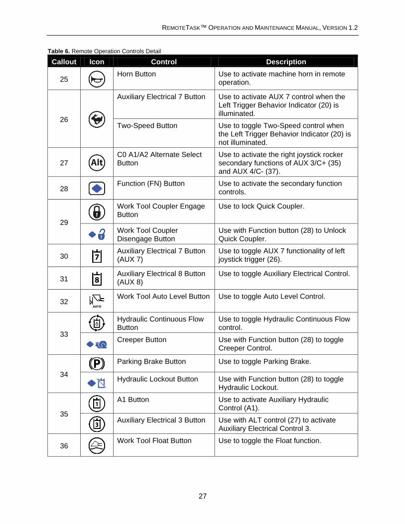
Table 6. Remote Operation Controls Detail
Callout Icon Control Description
25
Horn Button Use to activate machine horn in remote operation.
26
Auxiliary Electrical 7 Button
Use to activate AUX 7 control when the Left Trigger Behavior Indicator (20) is illuminated.
Two-Speed Button Use to toggle Two-Speed control when the Left Trigger Behavior Indicator (20) is not illuminated.
27
C0 A1/A2 Alternate Select Button
Use to activate the right joystick rocker secondary functions of AUX 3/C+ (35) and AUX 4/C- (37).
28
Function (FN) Button Use to activate the secondary function controls.
29
Work Tool Coupler Engage Button
Use to lock Quick Coupler.
Work Tool Coupler Disengage Button
Use with Function button (28) to Unlock Quick Coupler.
30
Auxiliary Electrical 7 Button (AUX 7)
Use to toggle AUX 7 functionality of left joystick trigger (26).
31
Auxiliary Electrical 8 Button (AUX 8)
Use to toggle Auxiliary Electrical Control.
32
Work Tool Auto Level Button Use to toggle Auto Level Control.
33
Hydraulic Continuous Flow Button
Use to toggle Hydraulic Continuous Flow control.
Creeper Button Use with Function button (28) to toggle
Creeper Control.
34
Parking Brake Button Use to toggle Parking Brake.
Hydraulic Lockout Button Use with Function button (28) to toggle
Hydraulic Lockout.
35
A1 Button Use to activate Auxiliary Hydraulic Control (A1).
Auxiliary Electrical 3 Button Use with ALT control (27) to activate Auxiliary Electrical Control 3.
36
Work Tool Float Button Use to toggle the Float function.

REMOTETASK™ OPERATION AND MAINTENANCE MANUAL, VERSION 1.2
28
37
A2 Button Use to activate Auxiliary Hydraulic Control (A2).
Auxiliary Electrical 4 Button Use with ALT control (27) to activate Auxiliary Electrical Control 4.
38
Auxiliary Electrical 6 Button Use to activate Auxiliary Electrical Control (C1)
39
Auxiliary Hydraulic Flow Rate Knob
Use to control the flow rate of Auxiliary Hydraulic Control (A1) and Auxiliary Hydraulic Control (A2).
40
Auxiliary Electrical 5 Button Use to activate Auxiliary Electrical Control 5 (C2)
41
Emergency Stop Button Use to initiate an emergency machine shutdown.
42 Creeper Control Knob Use to control Creeper level.
43
Engine Speed Control Knob Use to control Engine Speed.
44 - Controller Key Switch See above “Controller Key Switch”
section.
Secondary Function Controls
The AUX 7 button (30) enables the operator to toggle the function of the Left Joystick Trigger (26) from Two-Speed to the Auxiliary 7 electrical function.
The Function button (28) allows the operator to apply the secondary function of a control button on the RemoteTask™ Controller. To engage the secondary function of a control button, press and hold the Function (FN) button, then press and release the desired control button. Finally, release the FN button after the control button has been fully released.
The left hand joystick’s right button functions as an ALT control. When ALT (27) is depressed, the secondary functions of the right hand joystick buttons are activated. The left button (35) functions as the Auxiliary Electrical Control 3, and the right button (37) functions as Auxiliary Electrical Control 4.
The RemoteTask™ Controller does not include the following machine controls, but they can be configured in the machine cab prior to enabling remote operation:
Implement Sensitivity Control
Hystat Sensitivity Control
Front and Rear Work Light Control
Ride Control

REMOTETASK™ OPERATION AND MAINTENANCE MANUAL, VERSION 1.2
29
Remote Knob Controls Detail
The remote knob controls provide variable control settings for the hydraulic flow rate, travel
speed, and engine speed.
Table 7. Remote Knob Control Detail
Auxiliary Hydraulic Flow Rate Knob (39)
Icon Description
The Auxiliary Hydraulic Flow Rate Knob varies the flow rate of the Auxiliary Hydraulic A1 control (35) and the Auxiliary Hydraulic A2 control (37). Move the knob clockwise to increase the flow rate. Move the knob counter clockwise to decrease the flow rate.
Creeper Control Knob (42)
Icon Description
The Creeper Control Knob allows the operator to select a maximum machine travel speed at full joystick movement. Move the knob clockwise to increase travel speed. Move the knob counter clockwise to decrease travel speed.
Engine Speed Control Knob (43)
Icon Description
The Engine Speed Knob sets a constant engine speed, ranging from low engine idle to high engine idle. Move the knob clockwise to increase engine speed. Move the knob counter clockwise to decrease engine speed.

REMOTETASK™ OPERATION AND MAINTENANCE MANUAL, VERSION 1.2
30
Remote Joystick Detail - Left Hand
The RemoteTask™ Controller joysticks operate using the Caterpillar Joystick Control Pattern 1.
More detailed information on joystick control patterns can be found in the applicable CAT
machine Operation and Maintenance manual. For remote joystick button controls, refer to
Table 6.
Figure 8. Left Hand Joystick
Forward Travel: Push the joystick forward in order to travel forward.
Right Turn: Move the joystick to the right in order to turn the machine to the right
Backward Travel: Pull back on the joystick in order to travel in reverse
Left Turn: Move the joystick to the left in order to turn the machine to the left.
Whether operating the machine from the rear, facing forward or the front,
backing out, the functionality of the remote controls does not change. If
operating from the front of the machine, the operator’s perspective of the
machine controls will be opposite.

REMOTETASK™ OPERATION AND MAINTENANCE MANUAL, VERSION 1.2
31
Remote Joystick Detail - Right Hand
The RemoteTask™ Controller joysticks operate using the Caterpillar Joystick Control Pattern 1.
More detailed information on joystick control patterns can be found in the applicable CAT
machine Operation and Maintenance manual. For remote joystick button controls, refer to
Table 6.
Figure 9. Right Hand Joystick
Lower: Push the Joystick forward in order to lower the work tool.
Raise: Pull the joystick back in order to raise the work tool.
Dump: Move the Joystick to the right in order to tilt the work tool downward
Tilt Back: Move the joystick to the left in order to tilt the work tool upward.
Remote work tool controls need to be used in conjunction with an applicable
Work Tool Operation and Maintenance Manual to fully understand the functions
of each control.

REMOTETASK™ OPERATION AND MAINTENANCE MANUAL, VERSION 1.2
32
Remote Work Tools Detail
Only use work tools approved for the machine. Refer to the machine Operation and Maintenance Manual for a list of approved work tools. Use remote work tool controls in conjunction with an applicable Work Tool Operation and Maintenance Manual to fully understand the functions of each control.
The RemoteTask™ system is designed to operate all approved CAT machine work tools. The work tool control interfaces of the RemoteTask™ Controller are designed to mimic the controls inside the cab as closely as possible. This section shows the mapping between the RemoteTask
TM Controller and in cab controls. Consult the CAT Operation and Maintenance
Manual for the machine for a list of approved work tools. For operation of specific work tools, reference the applicable Operation and Maintenance Manual for that work tool.
Figure 10. In-Cab Work Tool Controls
Figure 11. RemoteTask
TM Controller Work Tool Controls.
26) Auxiliary Electrical 7 / Two-Speed button
27) C0 A1/A2 Alternate Select Button
38) Auxiliary Electrical 6 Button
40) Auxiliary Electrical 5 Button
35) A1 Button
ALT 35) Auxiliary Electrical 3 Button
37) A2 Button
ALT 37) Auxiliary Electrical 4 Button
The AUX 7 button (30) toggles the function of the left joystick trigger (26) between: AUX 7 and Two-Speed control.
The Alternate Select Button (27) toggles the function of the right joystick buttons (35 and 37).

REMOTETASK™ OPERATION AND MAINTENANCE MANUAL, VERSION 1.2
33
5 - Safety Features
The RemoteTaskTM
has a number of built-in features to improve safety during remote operation.
Emergency Stop
The RemoteTaskTM
system includes an emergency stop button on both the controller (41) and
the machine. These buttons are used to bring the machine to a stop in the event of an
emergency. Press the Emergency Stop button to initiate an emergency stop. Once pressed, the
machine will immediately stop remote commands, apply the parking brake, activate hydraulic
lockout, and turn off the engine. To release, turn the Emergency Stop button clockwise, restart
engine, and press the Parking Brake Button (34) to release the parking brake and disengage
the hydraulic lockout.
In Cab Override
The RemoteTask system includes an override that disables remote operation if the cab door is
open or a person is in the operator seat. When the cab door is opened or a person sits in the
operator seat, all remote commands will stop and the parking brake and hydraulic lockout will be
engaged. Once the door is closed and a person is no longer detected in the operator seat,
control will be returned to the RemoteTask system.
Degraded Communication Link
In the event of degraded or lost communication between the RemoteTaskTM
Controller and the
Machine Interface Module, the machine will come to an automatic stop, implement commands
will halt, and the engine speed will revert to low idle. If the communication link is not restored
within one second, the machine parking brake and hydraulic lockout will be applied.
The following situations will cause degraded or lost communication:
The maximum operating range has been exceeded.
No line-of-sight between the controller and machine.
RemoteTaskTM
Controller batteries need to be charged.
RF Interference from other systems communicating in the same frequency range.
The RemoteTaskTM
system has been damaged.
To resume operation, determine and resolve the cause of the communication loss and
reestablish the communication link. If the parking brake and hydraulic lockout have been
engaged, press the Parking Brake Button (34) to release the parking brake and disengage the
hydraulic lockout.

REMOTETASK™ OPERATION AND MAINTENANCE MANUAL, VERSION 1.2
34
Man-Down Feature
If the RemoteTaskTM
Controller is tilted over 45o in any direction, the system will lockout machine
motion. The machine will come to an automatic stop, implement commands will halt, and the
engine speed will revert to low idle. After one second of the RemoteTask™ Controller tilting, the
machine parking brake and hydraulic lockout will be applied.
To resume operation after the Man Down feature has been triggered, level the RemoteTask
TM
Controller. If the parking brake and hydraulic lockout have been engaged, press the Parking
Brake Button (34) to release the parking brake and disengage the hydraulic lockout.
Implement Lowering with Engine Stopped
Do not approach the machine if the Active Indicator (amber beacon) is
flashing. Verify with the operator that it is safe to approach the machine.
If the machine engine fails while remotely operating and the implement arm is raised, the
following steps can be used to lower the implement without the engine running if the
accumulator is charged:
1. Power cycle the RemoteTaskTM
Controller.
2. Once the controller is powered on again, the Communication Link Indicator (green beacon) on the machine will begin to blink.
3. Press the Parking Brake Button (34) to disengage the hydraulic lockout. The Active Indicator (amber beacon) will begin to blink.
4. Press the right joystick forward to lower the implement fully to the ground.
a. If implement does not lower, try to recharge the accumulator by cranking the engine for fifteen seconds.
b. If the implement still does not lower, complete the next step and refer to the CAT Operation and Maintenance Manual for alternate lowering procedure.
5. Complete the Remote Shutdown Procedure and Return Machine to Manual
Operation.

REMOTETASK™ OPERATION AND MAINTENANCE MANUAL, VERSION 1.2
35
6 - Remote Operation
This section guides the operator through switching the machine between manual and remote
mode and procedures for system startup and shutdown.
The operator is responsible for safely operating the remote machine.
Ensure the remote operation area is clearly marked and personnel do not enter
the area during remote operation. Verify site personnel are aware the system will
be operating remotely. Maintain line-of-sight with the machine at all times during
remote operation.
All personnel must keep a safe distance from remote machine operation
area. The machine can be operated without a person in the cab. Personnel who
are within the operation area of a remote control machine may not be visible to
the remote operator, which may result in personal injury or death. Always check
with the operator before approaching the machine.
Do not approach the machine if the Active Indicator (amber beacon) is
flashing. Verify with the operator that it is safe to approach the machine.
Do not enter the cab if the machine is remotely enabled. Verify the Remote
Enable Interface is in the OFF position and key is removed.
Make sure the machine is configured for Caterpillar Joystick Control Pattern 1
before enabling remote operation.
Do not remotely operate the machine if the Remote Enable Interface
‘Service’ light is illuminated red. Resolve using the Troubleshooting section.
If the ‘Service’ light continues to be illuminated, contact a CAT dealer.
The RemoteTask
TM Controller has a built-in inclinometer which will automatically
stop the machine when the console is tilted past 45 degrees in any direction.

REMOTETASK™ OPERATION AND MAINTENANCE MANUAL, VERSION 1.2
36
Transition Machine to Remote Operation
The machine should be configured for Caterpillar Joystick Control Pattern 1
before enabling remote operation.
Do not remotely operate the machine if the Remote Enable Interface
‘Service’ light is illuminated red. Resolve using the Troubleshooting section.
If the ‘Service’ light continues to be illuminated, contact a CAT dealer.
Do not operate the machine remotely with the in-cab AUX 8 control enabled
because remote control of this feature will not be possible. If the AUX 8 control
is enabled in the cab, the red ‘Service’ light will illuminate when the Remote
Enable Interface key switch is in the ON position.
1. Park the machine in a safe area to begin remote operation.
2. Engage the parking brake.
3. Set the engine speed to low idle.
4. Lower implement completely.
5. Engage the hydraulic lockout switch.
6. Ensure the machine is configured for joystick pattern 1.
7. Set desired machine controls that are not supported remotely:
a. Implement Sensitivity Control
b. Hystat Sensitivity Control
c. Front and Rear Work Light Control
d. Ride Control
8. Shut down the machine engine and remove the machine key.
9. Ensure cab seat is empty and the cab door is closed.
10. Insert the machine key into the Remote Enable Interface and turn to the ON position. The green ‘Ready’ light on the Remote Enable Interface will illuminate.
11. Verify that Remote Enable Interface ‘Service’ light is not illuminated.

REMOTETASK™ OPERATION AND MAINTENANCE MANUAL, VERSION 1.2
37
Remote Startup Procedure
The operator is responsible for safely operating the remote machine.
Ensure the remote operation area is clearly marked and personnel do not enter
the area during remote operation. Verify site personnel are aware the system will
be operating remotely. Maintain line-of-sight with the machine at all times during
remote operation.
1. Inspect the system
a. Inspect the RemoteTaskTM
, machine, and work tool for damage or leaks.
b. Verify the machine has sufficient battery, fuel, oil, water, etc.
2. Transition Machine to Remote Operation (defined above)
3. Put on RemoteTaskTM
Controller
a. Place head through the center of the shoulder straps so that one strap rests on each shoulder.
b. Bring the back clips underneath each arm and fasten to the designated holes on the back of the RemoteTask™ protection cage.
c. Ensure the controller is secure, comfortable, and level.
4. Power on RemoteTask Controller
a. Turn the RemoteTask™ Controller key switch (44) to the ON position.
b. Verify all LED indicators illuminate and cycle through their applicable colors.
c. Verify the Communication Link Indicator (green beacon) begins to blink on the
desired machine.
5. Start Machine Engine
a. On the RemoteTask Controller, verify the Engine Speed Control Knob (43) is set to low idle.
b. Turn the RemoteTask™ Controller key switch (44) to the ENGINE START position and hold until the engine starts. The Engine Off Indicator (16) will turn off once the engine has started.
6. Confirm Remote Controls
a. Release the parking brake and hydraulic lockout by pressing the Parking Brake Button (34).
b. On the machine, verify the Active Indicator (amber beacon) begins to blink.
c. Verify remote driving controls and implement controls are functioning properly.

REMOTETASK™ OPERATION AND MAINTENANCE MANUAL, VERSION 1.2
38
Remote Shutdown Procedure
Stopping the engine before allowing it to cool can result in overheating and
accelerated wear of the engine components. Always run the engine at low idle
for five minutes to cool down the engine. Excessive temperatures in the
turbocharger housing (if equipped) could cause oil cooking problems.
Access to the cab door may be obstructed if the implement and work tool are not
completely lowered prior to powering down the RemoteTask™ Controller.
1. Park the machine.
2. Set the engine speed to low idle.
3. Engage the Parking Brake (34).
4. Lower the implement completely.
5. Engage the Hydraulic Lockout (FN + 34).
6. Verify the Active Indicator (amber beacon) turns off.
7. CAT recommends cooling the engine down before shutting it off by running the engine at low idle for 5 minutes.
8. After the cool down period is complete, turn the RemoteTask™ Controller key switch (44) to the OFF position. This will turn off the machine engine and power down the RemoteTask™ Controller.

REMOTETASK™ OPERATION AND MAINTENANCE MANUAL, VERSION 1.2
39
Return Machine to Manual Operation
All personnel must keep a safe distance from remote machine operation
area. The machine can be operated without a person in the cab. Personnel who
are within the operation area of a remote control machine may not be visible to
the remote operator, which may result in personal injury or death. Always check
with the operator before approaching the machine.
Do not approach the machine if the Active Indicator (amber beacon) is
flashing. Verify with the operator that it is safe to approach the machine.
Do not enter the cab if the machine is remotely enabled. Verify the Remote
Enable Interface is in the OFF position and key is removed.
1. Complete the Remote Shutdown Procedure (defined above)
2. On the Remote Enable Interface, turn the key to the OFF position and remove the key.

REMOTETASK™ OPERATION AND MAINTENANCE MANUAL, VERSION 1.2
40
Battery Replacement and Charging
The RemoteTask™ Controller is powered by four Li-Ion 18650 Cell 2600mAH internally
protected batteries. The RemoteTask™ System comes with a Nitecore i4 Intellicharger that can
recharge batteries via AC or 12V DC power cord. Review the instructions and safety information
accompanying the charger before charging the batteries.
Use only the provided batteries and charger with the RemoteTask
Controller. The use of third party batteries or chargers could damage the
hardware and void the product warranty.
The batteries are accessible through a removable door on the bottom center of the
RemoteTaskTM
Controller. The battery door is fastened with a tool-less, quarter-turn fastener.
Turn fastener clockwise to remove battery compartment cover. To take out the batteries, pull the
internal ribbon until the batteries are released.
Make sure the ribbon is accessible when replacing the batteries. To close, align battery cover
with the edges of the battery compartment and turn fastener counter clockwise until cover is
secured.
Figure 12. RemoteTask
TM Battery Compartment
Return used batteries to an appropriate recycling facility. Check local laws and
regulations regarding appropriate battery recycling.

REMOTETASK™ OPERATION AND MAINTENANCE MANUAL, VERSION 1.2
41
7 - System Configuration
Pairing Controller with Machine
The RemoteTaskTM
Controller and Machine Interface Module must be paired to communicate.
The system should come paired; however, the following pairing instructions can be used if the
system needs to be re-paired to a different channel. The Controller can only be paired to one
machine at a time.
1. Initiate Pairing Mode for the RemoteTask™ Controller
a. With the RemoteTask™ Controller powered off, press and hold both the AUX 7 (30) and Auto Level (32) buttons and turn the RemoteTask™ Controller key switch (44) to POWER ON.
b. The icons for multilevel LED indicators will blink red to indicate pairing mode.
2. Initiate Pairing Mode on the Remote Enable Interface
a. Turn the Remote Enable Interface key switch from the OFF position to the PAIRING position and hold for three (3) seconds.
b. The green “Ready” light on the Remote Enable Interface will begin blinking rapidly, indicating that the machine is in pairing mode.
c. On the Controller, the multilevel LED indicators will illuminate green to indicate the current channel and the icons will stop blinking red.
3. Select desired frequency channel
a. Use AUX 6 (38) or AUX 5 (40) to change the channel, which is displayed as a pattern on the multilevel LED indicator.
b. Ensure that each RemoteTaskTM
system has a different channel pattern if using multiple machines remotely in the same operation area.
4. Finalize the pairing process.
a. Press AUX 8 (31) to confirm the frequency channel and exit pairing mode.
b. On the Remote Enable Interface, the green ‘Ready’ light will glow solid.
c. On the machine, the Communication Link Indicator (green beacon) should begin to blink.
d. The multilevel LED indicators will change to reflect signal, battery, and fuel values.
Pairing mode will timeout after two minutes. In pairing mode, the green
“Ready” light on the Remote Enable Interface will blink rapidly. Once a timeout
has occurred the light will glow solid, and the RemoteTask system will need to be
powered down to restart the pairing procedure.

REMOTETASK™ OPERATION AND MAINTENANCE MANUAL, VERSION 1.2
42
Shoulder Harness Attachment
The Shoulder Harness is designed to allow the Remote Controller to rest comfortably at the
operator’s midsection, supporting the weight of the RemoteTask™ Controller and keeping the
operator’s hands free to control the machine. The shoulder harness straps may also be
configured so that the Remote Controller rests on the operator’s side.
Ensure that the shoulder harness is securely fastened and the RemoteTask™
Controller is stable before remote operation.
Front Configuration
1. Remove both back strap clips from the holes in the protection cage.
2. Place head through the center of the shoulder straps so that one strap rests on each shoulder.
3. Bring the back clips underneath each arm and fasten to the designated holes on the back of the RemoteTask™ protection cage.
4. Ensure the controller is secure, comfortable, and sitting level. If necessary, adjust the straps to ensure a comfortable, supportive fit on the operator:
a. Back adjustment: affects the tightness of the harness around the body.
b. Front adjustment: adjusts the vertical height of the Remote Control Console.
Figure 13: Front Shoulder Harness Configuration

REMOTETASK™ OPERATION AND MAINTENANCE MANUAL, VERSION 1.2
43
Right Side Configuration
1. Unfasten both back strap clips from the cage.
2. Cross the left back strap behind the harness and clip it to the right side attachment point (see Figure 14).
3. The right strap end may be stowed away by inserting it under one of the fabric sections behind the mesh back.
4. Place head through left shoulder strap. The left strap should rest on the operator’s left shoulder, with the Remote Controller resting on the right hip.
5. Adjust straps for tightness as necessary.
Figure 14: Attach left clip to right attachment point.
Left Side Configuration
1. Unfasten both back strap clips from the cage.
2. Cross the right back strap behind the harness and clip it to the left side attachment point (see Figure 15).
3. The left strap end may be stowed away by inserting it under one of the fabric sections on the mesh back.
4. Place head through right shoulder strap. The right strap should rest on the operator’s right shoulder, with the Remote Controller resting on the left hip.
5. Adjust straps for tightness as necessary.
Figure 15: Attach right clip to left attachment point.

REMOTETASK™ OPERATION AND MAINTENANCE MANUAL, VERSION 1.2
44
8 - Maintenance
This section provides basic care and maintenance of RemoteTask™ system. Refer to the
applicable Operation and Maintenance manuals for additional maintenance information related
to the machine and work tools.
Do not approach the machine if the Active Indicator (amber beacon) is
flashing. Verify with the operator that it is safe to approach the machine.
Do not enter the cab if the machine is remotely enabled. Verify the Remote
Enable Interface is in the OFF position and key is removed.
Do Not Modify or Disassemble RemoteTask components or wiring.
Modifications could result in a shock hazard, product damage, or unexpected
operation. Opening, modifying, or repairing the RemoteTask will void any
applicable warranty and could prevent the device from operating properly.
Contact a CAT dealer if repairs or modifications are required.
Do Not Operate With Suspected Failures. If you suspect there is damage to
the RemoteTask, contact a CAT dealer to have it inspected before further use.
General Care
Use a damp cloth, and mild dish detergent if needed, to remove any mud, dirt, concrete, and
other materials to prevent clogging of the controls.
Do not clean the RemoteTask™ components under high pressure, with
solvents (such as benzene, thinner, ammonia), or with abrasive cleaners. If
water or other liquids get inside the RemoteTask™ Controller’s battery
compartment, immediately remove the batteries and allow the unit to air dry.

REMOTETASK™ OPERATION AND MAINTENANCE MANUAL, VERSION 1.2
45
Maintenance Schedule
Table 8. RemoteTask Maintenance Schedule
Service Interval Item Description
Weekly, or every 60 Operating Hours
Machine harnesses Verify wiring harnesses are secure. Verify wiring harnesses are not being pinched or damaged.
RemoteTask Parts List
Item Number Product Name
RT01 RemoteTask™
RT01-MI RemoteTask Machine Interface Assembly
RT01-MI-MIM Machine Interface Module
RT01-MI-MEI Machine ECM Interface
RT01-MI-MIH Machine Interface Harness
RT01-MI-UCM Under Cab Mounting Assembly
RT01-MI-UCH Under Cab Harness
RT01-MI-REI Remote Enable Interface
RT01-MI-UIH User Interface Harness
RT01-MI-AMB Active Indicator (amber beacon)
RT01-MI-GRN Communication Link Indicator (green beacon)
RT01-RC RemoteTask Controller
RT01-RC-RCU Remote Control Unit
RT01-RC-PC Protection Cage
RT01-RC-SH Shoulder Harness
RT01-RC-BAT Controller Batteries
RT01-RC-BC Controller Battery Charger
RT01-DOC RemoteTask Documentation Package
RT01-DOC-OMM Operation and Maintenance Manual
RT01-DOC-PIM Parts and Installation Manual
RT01-OPT RemoteTask Options
RT01-OPT-PRG Firmware Update / Programming Toolkit
RT01-OPT-ISO Remote control ISO warning label

REMOTETASK™ OPERATION AND MAINTENANCE MANUAL, VERSION 1.2
46
9 - Troubleshooting
Do not approach the machine if the Active Indicator (amber beacon) is
flashing. Verify with the operator that it is safe to approach the machine.
Do not enter the cab if the machine is remotely enabled. Verify the Remote
Enable Interface is in the OFF position and key is removed.
Do Not Modify or Disassemble RemoteTask
TM components or wiring.
Modifications could result in a shock hazard, product damage, or unexpected
operation. Opening, modifying, or repairing the RemoteTaskTM
will void any
applicable warranty and could prevent the device from operating properly.
Contact a CAT dealer if repairs or modifications are required.
Do Not Operate With Suspected Failures. If you suspect there is damage to
the RemoteTask, contact a CAT dealer to have it inspected before further use.
General Troubleshooting
This section provides general troubleshooting tips and information for solving operation issues
with the RemoteTask™ system.
Warnings and Safety Messages
Warning Feedback – If a warning light is illuminated, reference the Warning Feedback section of
the Operation and Maintenance Manual to determine the meaning of the warning and
recommended action.
Safety Features– If the machine does not operate normally during remote operation, reference
the Safety Features section of the Operation and Maintenance Manual and verify that features
such as Emergency Stop, Man-Down, etc. are not engaged.

REMOTETASK™ OPERATION AND MAINTENANCE MANUAL, VERSION 1.2
47
Startup
Verify that both the Remote Enable Interface and the RemoteTaskTM
Controller are powered
on.
If the RemoteTask Controller does not power on, reference the Battery Replacement and
Charging section of the Operation and Maintenance Manual. Verify that the controller
batteries are charged and installed properly. Replace batteries if necessary.
Controls
If a control does not perform its expected function during remote operation, check for the
following issues:
Verify the machine is equipped with the control. The RemoteTask™ system will not add
any additional functionality to the machine.
Verify that the control performs as expected during manual operation. If the control still
does not function normally during manual operation, reference the applicable CAT
Operation and Maintenance Manual to troubleshoot the issue.
RemoteTaskTM
Wire Harness Connections
All components of the RemoteTaskTM
wire harness assembly must be connected correctly in
order for remote OR manual operation to work. If any part of the RemoteTaskTM
Machine
Interface Assembly is removed or not connected properly, the machine will not operate in either
remote or manual mode.
Consult the RemoteTaskTM
Parts and Installation Manual for information regarding the
Machine Interface Assembly.
Verify wiring harnesses are secure.
Verify wiring harnesses are not pinched or damaged.

REMOTETASK™ OPERATION AND MAINTENANCE MANUAL, VERSION 1.2
48
Troubleshooting Issues
This section provides basic troubleshooting information for specific operation issues with the
RemoteTask™ system.
No Link between RemoteTask™ Controller and Machine
AND Possible Causes Solutions
Communication Link Indicator (green beacon) is blinking.
All other LED indicators behaving normally.
RemoteTask™ Controller and machine attempting to communicate.
Wait for approximately 30 seconds for communication to be established.
Wireless Link Status Indicator Light (45) icon is blinking red.
RemoteTask™ Controller is not paired with the machine.
Follow the steps in “Pairing Controller with Machine.”
Machine engine will not start remotely
AND Possible Causes Solution
Emergency Stop Warning Indicator (1) is illuminated.
RemoteTask Controller and/or Remote Enable Interface Emergency Stop Button Activated.
Turn Emergency Stop button clockwise to disengage.
Machine Fuel Level Indicator Light (47) is illuminated.
Machine does not have sufficient fuel to operate.
Add fuel to the machine.
Communication Link Indicator (green beacon)
is not illuminated.
Wireless Link Status Indicator Light (45) icon is illuminated red.
Machine is not in remote mode.
Machine is out of signal range.
Signal between machine and controller is obstructed.
Turn the REI key switch to the ON position.
Move controller within range of the machine.
Establish unobstructed line-of-sight with the machine.
Electrical System Warning (9) is illuminated.
Insufficient electrical power for machine operation.
Charge machine battery.
Replace necessary fuses.
RemoteTask Controller is tilted.
Man Down Feature activated.
Level the RemoteTask Controller. See “Man Down Feature” section.

REMOTETASK™ OPERATION AND MAINTENANCE MANUAL, VERSION 1.2
49
Linked machine will not operate
AND Possible Causes Solution
Emergency Stop Warning Indicator (1) is illuminated.
RemoteTask Controller and/or Remote Enable Interface Emergency Stop Button Activated.
Turn Emergency Stop button clockwise to disengage.
Parking Brake Indicator (24) is illuminated.
Machine Parking Brake is engaged.
Press the Parking Brake Button (34) to disengage.
RemoteTask Controller is tilted.
Man Down Feature activated.
Level the RemoteTask Controller. See “Man Down Feature.”
Work tool will not operate
AND Possible Causes Solution
Hydraulic Lockout Indicator Light (17) is illuminated.
Machine Hydraulic Lockout is engaged.
Press the Hydraulic Lockout Button (FN + 28) to disengage.
Machine stops suddenly during operation
AND Possible Causes Solution
Wireless Link Status Indicator Light (45) icon is illuminated red.
Machine is out of signal range.
Signal between machine and controller is obstructed.
Move controller within range of the machine.
Establish unobstructed line-of-sight with the machine.
RemoteTaskTM
Controller is tilted.
Man Down Feature activated.
Level the RemoteTaskTM
Controller. See “Man Down Feature.”

REMOTETASK™ OPERATION AND MAINTENANCE MANUAL, VERSION 1.2
50
Engine RPM increases spontaneously or will not decrease via Engine
Speed Control Knob
AND Possible Causes Solution
Diesel Particulate Filter Regeneration Warning (7) is illuminated.
Diesel Particulate Filter Regeneration in progress.
Continue normal operation. Engine Speed control will return upon completion of the Diesel Particulate Filter Regeneration process
AUX 8 Control will not disengage remotely
AND Possible Causes Solution
Red “Service” light on Remote Enable Interface is illuminated.
The AUX 8 control is engaged in the cab.
Return machine to manual operation. Disengage the in-cab AUX 8 control. Transition machine back to remote operation.
Red “Service” light on Remote Enable Interface is illuminated.
AND Possible Causes Solution
The AUX 8 control will not disengage.
The AUX 8 control is engaged in the cab.
Return machine to manual operation. Disengage the in-cab AUX 8 control. Transition machine back to remote operation.
The in-cab AUX 8 control is
not engaged.
One or more control outputs are faulted.
Contact a CAT dealer for support. Do not attempt to operate machine with suspected failures.

REMOTETASK™ OPERATION AND MAINTENANCE MANUAL, VERSION 1.2
51
Remote Controller does not power off immediately.
AND Possible Causes Solution
Communication Link Indicator (green beacon) is
not illuminated.
Wireless Link Status (45) icon is illuminated red.
Machine is not in remote mode.
The controller will attempt to communicate with the machine before powering down. Wait ~5 seconds for the Remote Controller to power down.
No link between machine and controller.
Reestablish the link (see “No Link between RemoteTask™ Controller and Machine” above).
Ensure that the machine engine is off before powering down the RemoteTask Controller.

REMOTETASK™ OPERATION AND MAINTENANCE MANUAL, VERSION 1.2
52
10 - Specifications
Table 9. RemoteTaskTM
System Specifications
Wireless Performance
Max. Operating range 1000 ft, (Line of Sight)
Frequency Band 2.4 – 2.48GHz
Technology Spread Spectrum
Hopping Channels 79
Transmit Power 125 mW
RemoteTask™ Controller Electrical
Battery Life 24+ Hours
Full Charge Time 7 hours, using provided charger
Battery Information Four Li-Ion 18650 Cell 2600mAH batteries with integrated protection circuitry
Environmental
Dust/ Water Resistance Machine Interface Module: IP 67 RemoteTask™ Controller: IP 65
Operational Temperature -20ºC (-4ºF) to 55ºC (131ºF)

REMOTETASK™ OPERATION AND MAINTENANCE MANUAL, VERSION 1.2
53
11 - FFC Compliance
This equipment has been approved for mobile applications where the equipment should be
used at distances greater than 20 cm from the human body (with the exception of hands, wrists,
feet, and ankles). Operation at distances less than 20 cm is strictly prohibited. This device
complies with Part 15 of the FCC Rules. Operation is subject to the following conditions: (1) This
device may not cause harmful interference, and (2) This device must accept any interference
received, including interference that may cause undesired operation. FCC ID: KQL– RM024
12 - Limited Warranty
TORC Robotics, Inc. (herein referred to as TORC) guarantees that the product(s) you have
purchased from TORC are free from defects in materials or workmanship for a period of one
year from the original date of purchase. Within this period TORC will, at its sole discretion,
repair or replace any components which fail under normal use. This warranty does not cover
failures due to abuse, misuse, accident, or unauthorized alterations or repairs. There are no
other warranties, expressed or implied, which extend beyond the description contained herein
including the implied warranty of merchantability and fitness for a particular purpose. TORC
expressly excludes all other warranties TORC’s liability is limited to the cost of repair or
replacement of the product. Such remedy shall be the sole and exclusive remedy for any breach
of warranty. TORC shall not be liable for: 1. Damage to other property caused by any defects in
the product, damages based upon inconvenience, loss of use of the product, loss of time, loss
of profits, loss of business opportunity, loss of goodwill, interference with business relationships,
or other commercial loss, even if advised of the possibility of such damages. 2. Any indirect or
other damages, whether incidental, consequential, or otherwise. 3. Any claim against the
customer by any other party.