Embed Size (px)
Citation preview
. (
' ... ,,: ....
SM-SD-1973
Tous modeles 484 0090
.Xnd·
>,,"' ".•]J'(f~~~..;~i"..z~'/·i:·{" ~ ':~::::M!J$ee J.Armarid Bombardier
. ".,;',.' .. ' w-.museebombardier.com
., ~ . ''' ..
,~ . . - ..
" 'j~'.)
. '" ~l' ~ .... ~ r 1>
I :_.
, ;:.'
' .. '~' ...
. ~ .
• J :
. ~') , . ,,~
, ~" 'iI>' .: -'.
. '" -' ..
;v;· f. .
". :.~
·.;·A··
Reproduction interdite/Reproduction Prohibited
INTRODUCTION
FOREWORD
This manual has been prepared by the Technical Information Center of Bombardier Limited, (Ski-Doo Division), and is intended primarily for use by authorized Ski-Doo dealers.
As a supplement edition, this manual covers only procedures and information, relating to the 1973 series of Ski-Doo snowmobiles, which differ from those stated in the 1972 Ski·Doo Shop Manual.
If you are not totally familiar with the '72 Shop Manual procedure(s), we suggest that a copy of the '72 manual be obtained. Refer to the section(s) required, familiarize yourself with the content, then refer to the '73 supplement for indication of change. If this manual does not include a supplement section the system/component requires no further procedure(s) other than that stated in the '72 manual.
This manual is not designed to relate step by step removal, disassembly, assembly or installation procedures.
In many cases, the exploded view of the system/component is sufficient to perform the necessary procedure, however, text accompanying the illustration must be read' and understood before commencing any practical application. Text contains important data necessary to perform the task.
ILLUSTRATIONS
The illustrations are conveniently located as close as possible to the written procedures and are meant to assist the user in identifying parts and components. In some cases, however, depending on model, they may not show the exact relation or arrangement of parts, as space within the manual does not permit. The figure shown is that which relates to the greatest number of models and servicing methods detailed.
GENERAL
All of the information, illustrations and component/system descriptions contained in this manual are correct at time of publication. Bombardier Limited, however, maintains a policy of continuous improvement of its products without imposing upon itself any obligation to install them on products previously manufactured.
IMPORTANT - If vehicle is still under warranty, read warranty conditions and exclusions, at back of manual, carefully, before commencing any procedure. Unrestricted tampering can invalidate your warranty.
WARNING: Skl-Doo snowmobile dealers have undergone extensive training and consequently, are completely familiar With precautionary steps that must be observed while service a vehicle. Where neccessary, thiS manual IS IIlterrupted WIth WARNINGS or CAUTIONS. It IS Imperative that they be followed closely. In case of doubt, always consult trained dealer staff.
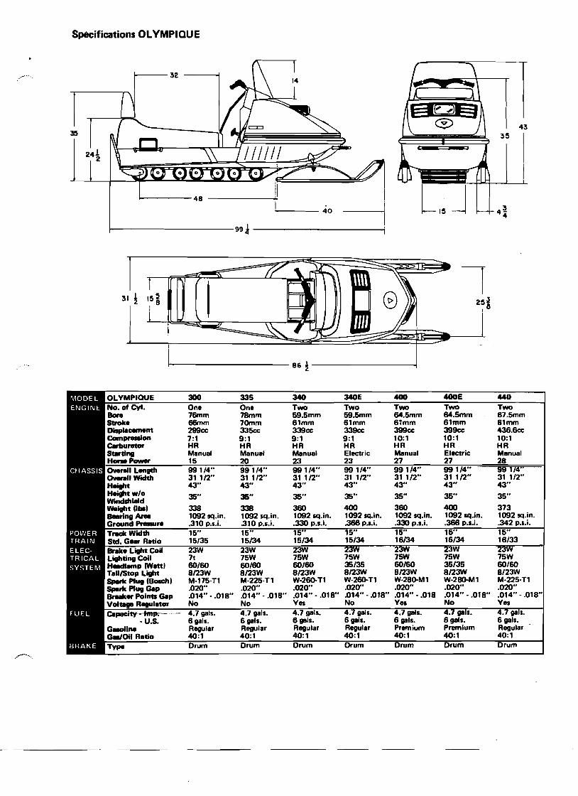
Specifications OLYMPIQUE
------40
~---------ggl-----------i
35
4~4
43
I
31 ! 15 ~ 8
I
86 i
25~ ,8
OLYMPIQUE 300 335 340 340E 400 400E 440 No. of CyI. One One Two Two Two Two Two Bore 76mm 78mm 59.5mm 59.5mm 64.5mm 64.5mm 67.5mm Stroke 66mm 70mm 61mm 61mm 61mm 61mm 61mm DispW:ement 299cc 335cc 339cc 339cc 399cc 399cc 436.6cc Compr.-ion 7:1 9:1 9:1 9:1 10:1 10:1 10:1 Cerburetor HR HR HR HR HR HR HR Sta'ting Manual Manual Manual Electric Manual Electric Manual Hone' 15 20 23 23 27 27 28 0 __1 Length 0-.11 WlClth H....t
99 1/4" 31 1/2" 43"
991/4" 31 1/2" 43"
991/4" 31 1/2" 43"
99 1/4" 31 1/2"43"
991/4" 31 1/2" 43"
99 1/4" 31 1/2" 43"
99 174" 31 112" 43"
Heiptw/o Windshield
35" 35" 35" 35" 35" 35" 35"
weight 0'" Beering Are. Ground Pre8ure
33S 1092 sq.in. .310 P.s.i.
338 1092 sq.in. .310 p.s.i.
360 1092 sq.in. .330 p.s.i.
400 1092 sq.in. .366 p.s.i.
360 1092 sq.in. .330 p.s.i.
400 1092 sq.in. .366 P.s.i•
373 1092 sq.in. .342 p.s.i.
TrKkWldth 15" 15" 15" 15" 15" 15" 15" Std. G_ Ratio 15/35 15/34 15/34 15/34 16/34 16/34 16/33 Brake Light Coil Lighting Coil H.-dIamp ewatt) TaU/Stop Light Spark Plug CBosch' Spark Plug Gap Breaker Points Gap Voltage Regulator
23W 7t 60/60 8/23W M·175-n .020" .014" ..018" No
23W 75W 60/60 8/23W M-225-n .020" .014" - .018" No
2 75W 60/60 8/23W W-260-T1 .020" .014" - .018" Yes
2W 75W 35/35 8/23W W-260·T1 .020" .014"· .018" No
2 15W 60/60 8/23W W·28G-M1 .020" .014" - .018 Yes
15W 35/35 8/23W W·28O-M1 .020" .014" - .018" No
2 75W 60/60 8/23W M-225-T1 .020" .014" - .018" Yes
Capacity Imp. -----U.S.
GaoIi.. G8II0il Ratio
4.7 gals. 6 gals. Regular 40:1
4.7 gals. 6gals. Regular 40:1
4.7 gals. 6gels. Regular 40:1
.7 gals. 6gals. Regular 40:1
.7 gals. 6gals. Premium 40:1
ge s. 6gals. Premium 40:1
4.7 ga s. 6 gals. Regular 40:1
Type Drum Drum Drum Drum Drum Drum Drum
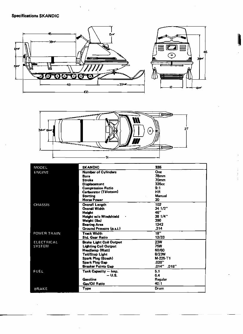
Specifications SKANDIC
~n~~::rz::3ri~~1
34LId'I9WL--=~~~~J f------------9J------------J
SKANDIC 335 Number of Cylinders One Bore 78mm Stroke 70mm Displacement 335cc Compression Ratio 9:1 Carburetor (Tillotsont HR Starting Manual HorsePower 20 Overall Length 102 Overall Width 34 1/2·· Height 46" Height w/o Windshield 38 1/4" Weight (Ibs) 390 Bearing Area 1242 Ground Pressure (p.s.i.) .314 Track Width 18" Std. Gear Ratio 12/33 Brake Light Coil Output 23W Lighting Coil Output 75W Headlamp (Watt) 60/60 Tail/Stop light 8/2:M Spark Plug (Bosch) M·225·T1 Spark Plug Gap .020" Breaker Points Gap .014" .018" Tank Capacity Imp. 5.1
-U.S. 6.4 Gasoline Regular Gas/Oil Ratio Type
40:1 Drum
35
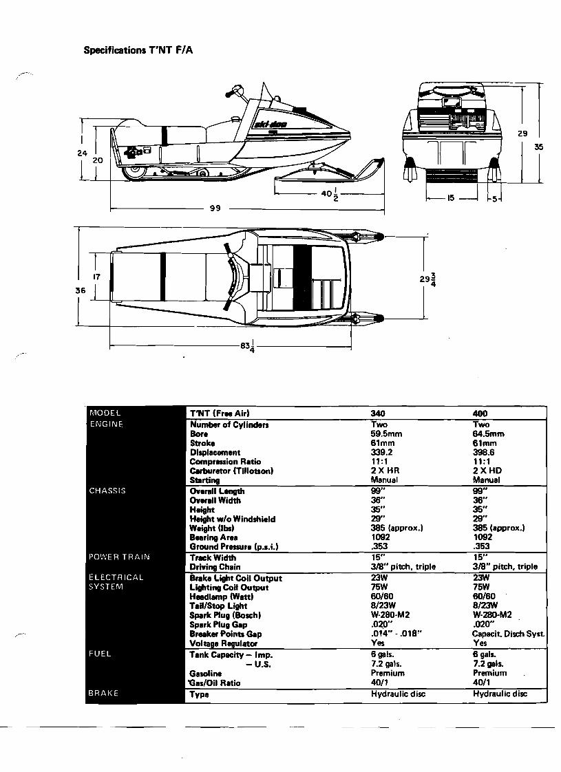
Specifications T'NT F/A
n 1----- 40! -----1
2 99
36
17
1------------831-------~ 4
T'NT (Fr.. Air. 340 400 Number of Cylinders Two Two Bore 59.5mm 64.5mm Stroke 61mm 61mm Displacement 339.2 398.6 Compression Ratio 11 :1 11 :1 Carburetor (Tillotson. 2X HR 2XHD Starting Manual Manual Overall Leogth 99" 99" Overall Width 36" 36" Height 35" 35" Height wlo Windshield 29" 29" Weight (lbI) 385 (approx.1 385 (approx.1 BeeringArea 1092 1092 Ground Preuure (p.s.i.l .353 .353 Track Width 15" 15" Driving Chain 318" pitch, triple 318" pitch, triple Brake Light Coil Output 23W 2:1'N Lighting Coil Output 75W 75W Heedlamp (Watd 60160 60160 TaillStop Light 8123W 812:1'N Spark Plug (Bosch. W·280-M2 W·280·M2 Spark Plug Gap .020" .020"
~- Breeker Points Gap .014" -.018" Capacit. Disch Syst. Volta R ulator Ves Ves Tank Capacity - Imp. 6 gals. 6 gals.
- U.S. 7.2 gals. 7.2 gals. Premium Premium 4011 4011 Hydraulic disc Hydraulic disc
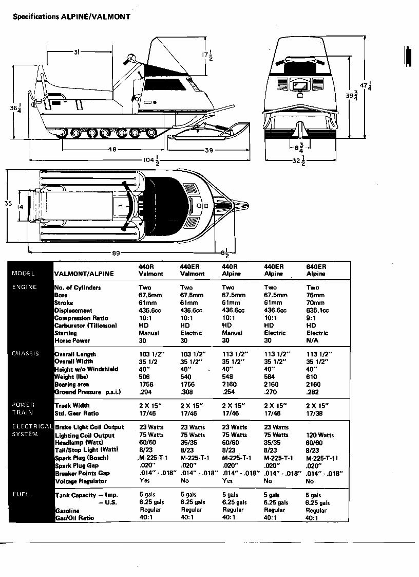
Specifications ALPINE/VALMONT
I~
..-.------------ 104 1 2-----------'
0
!89 2
440R 440ER 440R 440ER 640ER Valmont Valmont Alpin. Alpin. Alpin.
No. of Cylinders Two Two Two Two Two Bor. 67.5mm 67.5mm 67.5mm 67.5mm 76mm Stroke 61mm 61mm 61mm 61mm 70rnm Displacement 436.6cc 436.6cc 436.6cc 436.6cc 635.1cc Compression Ratio 10:1 10:1 10:1 10:1 9:1 Carbur.tor (Tillotson) HD HD HD HD HD Staning Manual Electric Manual Electric Electric HorsePow.r 30 30 30 30 N/A
Overall L.ngth 103 1/2" 103 1/2" 113 1/2" 113 1/2" 113 1/2" Overan Width 351/2 351/2" 35 1/2" 35 1/2" 35 1/2"
.ight w/o Windshi.ld 40" 40" 40" 40" 40" eight (lbs) 506 540 548 584 610
Bearing area 1756 1756 2160 2160 2160 round Pr....r. p.s.i.) .294 .308 .254 .270 .282
2 X 15" 2 X 15" 2 X 15" 2 X 15" 2 X 15" 17/46 17/46 17/46 17/46 17/38
• Bl'8k. Light Coil Output 23 Watts 23 Watts 23 Watts 23 Watts Lighting Coil Output 75 Watts 75 Watts 75 Watts 75 Watts 120 Watts Headlamp (Watt) 60/60 35/35 60/60 35/35 60/60 Tail/Stop Light (Watt) 8/23 8/23 8/23 8/23 8/23 Spark Plug (Bosch) ,M-225-T-1 M-225-T-1 M-225-T-1 M-225-T-1 M-225-T·11 Spark Plug Gap .020" .020" .020" .020" .020" Breaker Points Gap .014" - .018" .014" - .018" .014" - .018" .014" •.018" .014" - .018" Voltage Regulator Yes No Yes No No
ank Capacity - Imp. 5 gals 5 gals 5 gals 5 gals 5 gals -U.S. 6.25 gals 6.25 gals 6.25 gals 6.25 gals 6.25 gals
Regular Regular Regular Regular Regular 40:1 40:1 40:1 40:1 40:1
1-1
1·01·01
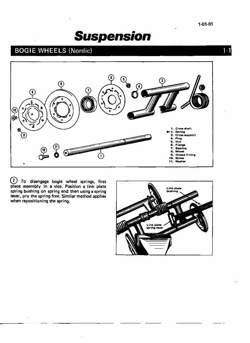
SUospension BOGIE WHEEL c
•
~~. sCroD shaft • pring
3. Cro•••• Plug support
5. Nut 6. Flange 7. Baarlng 8. Wh_l 9. Gra.. f10. Scr_
e Inlng
__________~'~'~.V;Washer
CD To disenpla~e assembl ga.ge bogie whee . :pnn bUshin:o~n a yice. Positi~:pnngs, first
gever, pry the s . spnng end then ~ link plate when repositio p!,ng free. Similar uSing a spring
nlng the spring. method applies
1-02-02
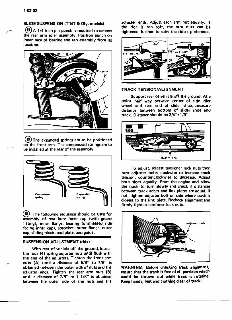
SLIDE SUSPENSION (T'NT & Oly. models)
@A 1/4 inch pin punch is required to remove the rear arm idler assembly. Position punch on inner race of bearing and tap assembly from its location.
® The expanded springs are to be positioned on the front arm. The compressed springs are to be installed at the rear of the assembly.
Compressed spring
® The following sequence should be used for assembly of rear hub: Inner cap (with grease fitting), inner flange, bearing (unshielded side facing inner cap), sprocket, outer flange, outer cap, sliding block, end plate, and guide.
SUSPENSION ADJUSTMENT (ride)
With rear of vehicle off the ground, loosen the four (4) spring adjuster nuts until flush with the end of the adjusters. Tighten the front arm nuts (A) until a distance of 5/8" to 7/8" is obtained between the outer side of nuts and the adjuster ends. Tighten the rear arm nuts (B) until a distance of 7/8" to 1 118" is obtained between the outer side of the nuts and the
adjuster ends. Adjust each arm nut equally. If the ride is too soft, the arm nuts can be tightened further to suite the riders preference.
TRACK TENSIONIALIGNMENT
Support rear of vehicle off the ground. At a point half way between center of side idler wheel and rear end of slider shoe, .measure distance between bottom of slider shoe and track. Distance should be 3/4"±1/8".
f· 3/4"± lIS"
To adjust, release tensioner lock nuts then turn adjuster bolts clockwise to increase track tension, counter-clockwise to decrease. Adjust both sides equally. Start the engine and allow the track to turn slowly and check if distances between track edges and link plates are equal. If not, tighten adjuster bolt on side where track is closest to the link plate. Recheck alignment and firmly tighten tensioner lock nuts.
WARN ING: Before checking track alignment, ensure that the track is free of all particles which could be thrown out while track is rotating. Keep hands, feet and clothing clear of track.
--
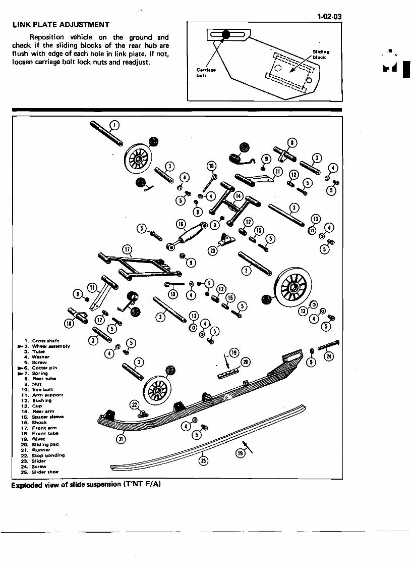
1-02·03 LINK PLATE ADJUSTMENT
Reposition vehicle on the ground and check if the sliding blocks of the rear hub are flush with edge of each hole in link plate. If not, loosen carriage bolt lock nuts and readjust.
1. Cross Ihaft ~ 2. Wheel auembly
3. Tube 4. Walher 5. Screw
~S. Coner pin ~ 7. Spring
B. Rear tube 9. Nut
10. Eye bolt 1 1. Arm IUpport 12. Bushing 13. Cup 14. RNr arm 15. Spacer 11_. 1S. Shock 17. Front.,.m 1B. Front tube 19. Rlv.t 20. Sliding pad 21. Runner 22. Stop bonding 23. Slider 24. Screw 25. Slider shoe
Exploded view of slide suspension (T'NT F/A)
.•.\ .• I.'~·~., ...... .,,:•••• ~....... ~""'•• __ ·"""~'·~~· ••• '''''''''''''''~'''_•• A''' ...~ ' .. -J4j~ .'~ .~, ~
-···-"~~l_
1-02-04
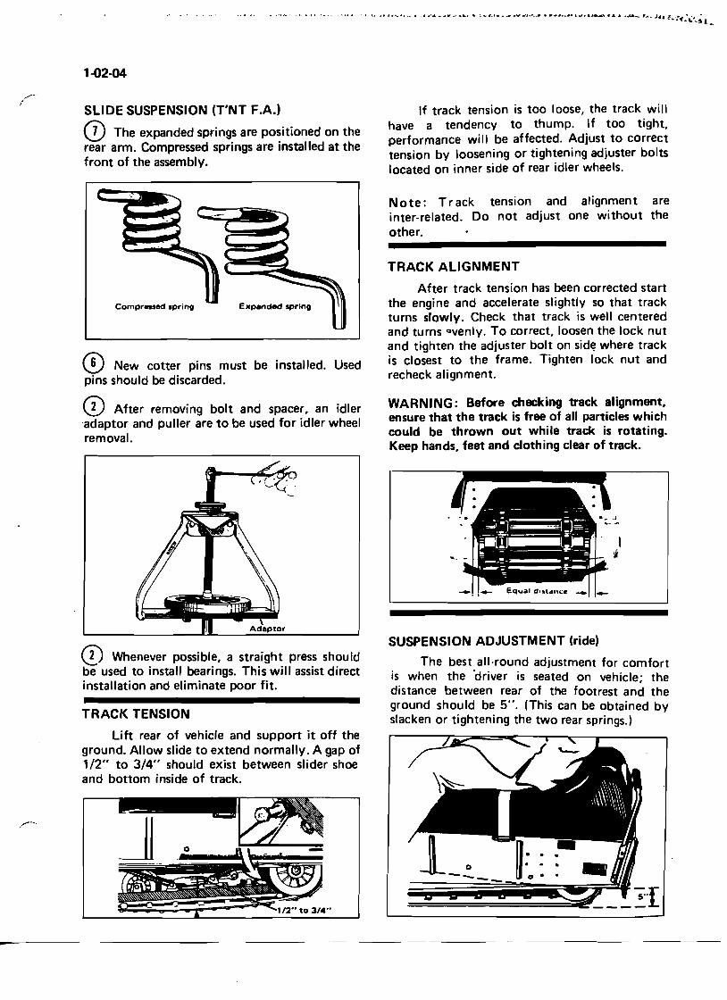
SLIDE SUSPENSION (T'NT F.A.)
CD The expanded springs are positioned on the rear arm. Compressed springs are installed at the front of the assembly.
Compressed sprinD Expanded sprinD
® New cotter pins must be installed. Used pins should be discarded.
CD After removing bolt and spacer, an idler 'adaptor and puller are to be used for idler wheel removal.
o Whenever possible, a straight press should be used to install bearings. This will assist direct installation and eliminate poor fit.
TRACK TENSION
Lift rear of vehicle and support it off the ground. Allow slide to extend normally. A gap of 1/2" to 3/4" should exist between slider shoe and bottom inside of track.
If track tension is too loose, the track will have a tendency to thump. If too tight, performance will be affected. Adjust to correct tension by loosening or tightening adjuster bolts located on inner side of rear idler wheels.
Note: Track tension and alignment are inter-related. Do not adjust one without the other.
TRACK ALIGNMENT
After track tension has been corrected start the engine and accelerate slightly so that track turns slowly. Check that track is well centered and turns Qvenly. To correct, loosen the lock nut and tighten the adjuster bolt on sid~ where track is closest to the frame. Tighten lock nut and recheck alignment.
WARNING: Before checking track alignment, ensure that the track is free of all particles which could be thrown out while track is rotating. Keep hands, feet and clothing clear of track.
SUSPENSION ADJUSTMENT (ride)
. The best.all-round adjustment for comfort IS. when the driver is seated on vehicle; the dIstance between rear of the footrest and the ground sho~ld b~ 5". (This can be obtained by slacken or tightening the two rear springs.)
1
1-04-01
Suspension /
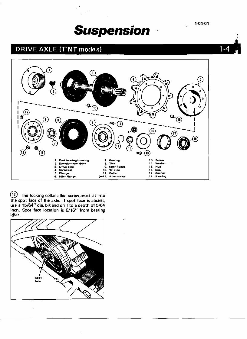
DRIVE AXLE (T'NT models) 1-4 '
CD I
1. End beerlng housing 7. Beering 13. Screw 2. Speedometer drive 8. Tire 14. Wesher 3. Drive exle 9. Idler flenge 15. Nut 4. Sprocket 10. '0' ring 16. SeeI 5. Flenge 11. Coller 17. Specer 6. Idler flenge '-12. Allen screw lB. B.ering
® The locking collar allen screw must sit into the spot face of the axle. If spot face is absent, use a 15/64" dia. bit and drill to a depth of 5/64 inch. Spot face location is 5/16" from bearing idler.
1-04-02
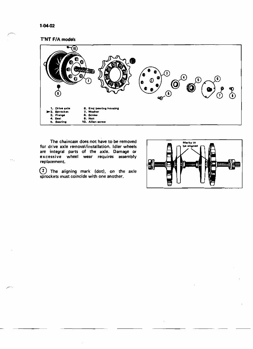
T'NT F/A models
1. Drlv. axl. 6. End b.arlng hou.lng ~2. Sprocket 7. Walh.r
3. Flange 8. $cr_ 4. Seal 9. Nut 5. S.8rlng 10. AII.n .craw
The chaincase does not have to be removed for drive axle removal/installation. Idler wheels are integral parts of the axle. Damage or excessive wheel wear requires assembly replacement.
CD The aligning mark (dod, on the axle sprockets must coincide with one another.
F/A
1-05-01
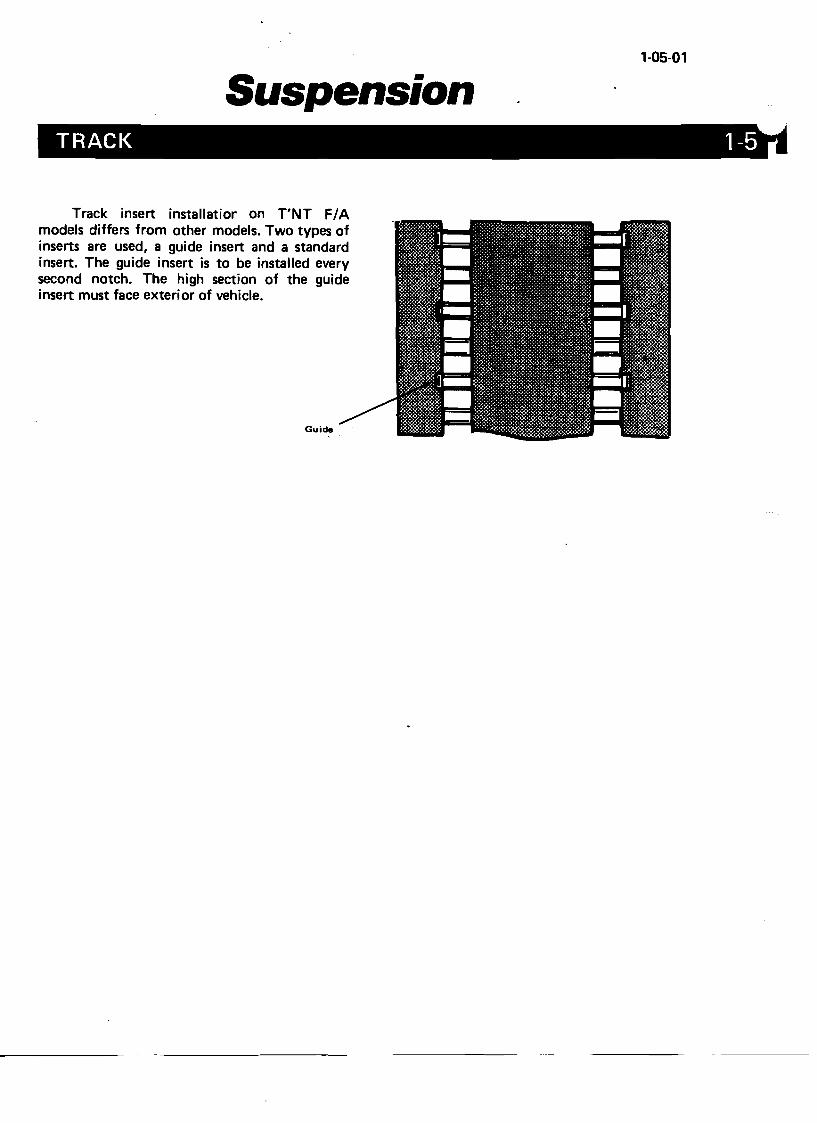
Suspension TRACK 1-5
Track insert installatior on T'NT models differs from other models. Two types of inserts are used, a guide insert and a standard insert. The guide insert is to be installed every second notch. The high section of the guide insert must face exterior of vehicle.
Guide
I
..
1-06-01
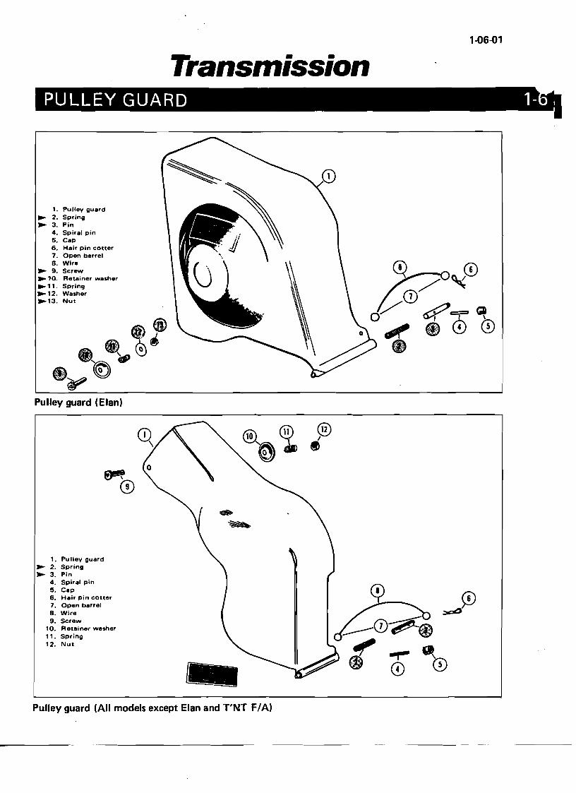
Transmission PULLEY GUARD 1
1. Pulley guard ~ 2. Spring ~ 3. Pin
4. Spiral pin 5. Cap 6. Hair pin cotter 7. Open barrel B. Wire
~ 9. Screw ~ 10. Retainer washer ~11. Spring ~12. Washer ~13. Nut
Pulley guard (Elan)
~o
0)
1. Pu lIey guard ~ 2. Spring ~ 3. Pin
4. Spiral pin 5. Cap 6. Hair pin cotter 7. Open barrel 8. Wire 9. Screw
10. Retainer washer 11. Spring 12. Nut
Pulley guard (All models except Elan and T'NT F/A)
,r--.
(
1-06-02
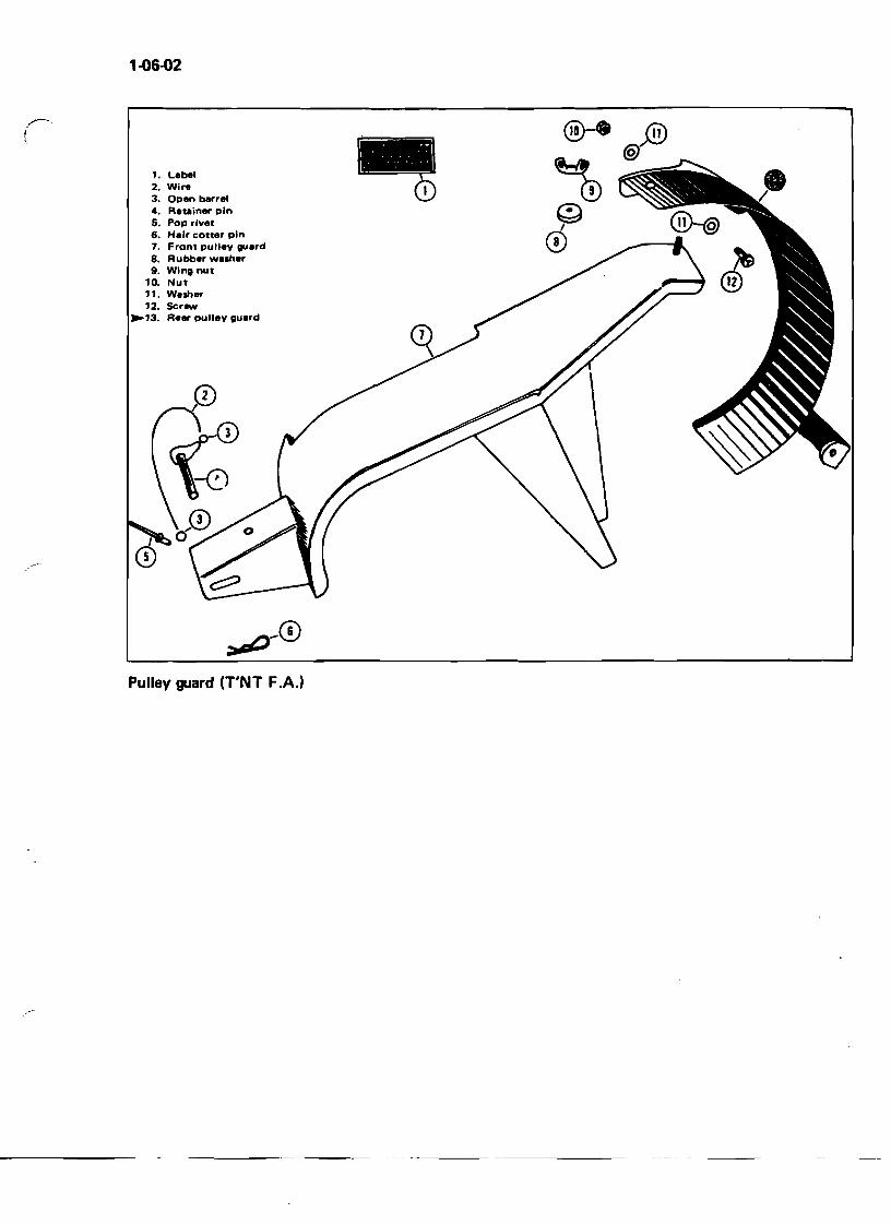
t. Lebel 2. Wlr. CD3. Open berrel •4. Reuiner pin 5. Pop rivet 6. Heir cotter pin 7. Front pulley guerd 8. Rubber wesher 9. Wing nut
10. Nut 11. Wesher 12. Scr_
~13. Rear pulley guerd
~-®
Pulley guard (T'NT F.A.)
1-08-01
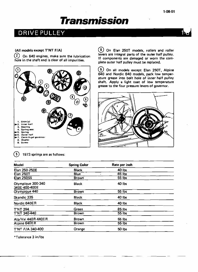
Transmission DRIVE PULLEY 1
(All models except T'NT F/A) CD On Elan 250T models, rollers and roller levers are integral parts of the outer half pulley. CD On 640 engines, make sure the lubrication If components are damaged or worn the comhole in the shaft end is clear of all impurities. plete outer half pulley must be replaced.
CD On all models except Elan 250T, Alpine 640 and Nordic 640 models, pack low temperature grease into bolt hole of inner half pulley shaft. Apply a light coat of low temperature grease to the four pressure levers of governor.
~7. Centrifugal governor 8. Washer 9. Screw
CD 1973 springs are as follows:
Model Spring Color Rate per inch
Elan 250-250E Black 40 Ibs Elan 250T Blue 651bs Elan 25055 Brown 551bs
Olympique 300-340 Black 40lbs 340E-400-400E Olympique 440 Brown 551bs
5kandic 335 Black 40lbs
Nordic 640E R Black 40 Ibs
T'NT 294 Green 851bs T'NT 340-440 Brown 551bs
Alp/Val 440R-440ER Brown 551bs Alpine 640ER Brown 551bs
T'NT F/ A 340-400 Orange 50 Ibs
*Tolerance 3 in/lbs
1. Shim(s) ~2. Inner half
3. Bearing 4. Spring seat
~5. Spring ~6. Outer half
1'()8-02
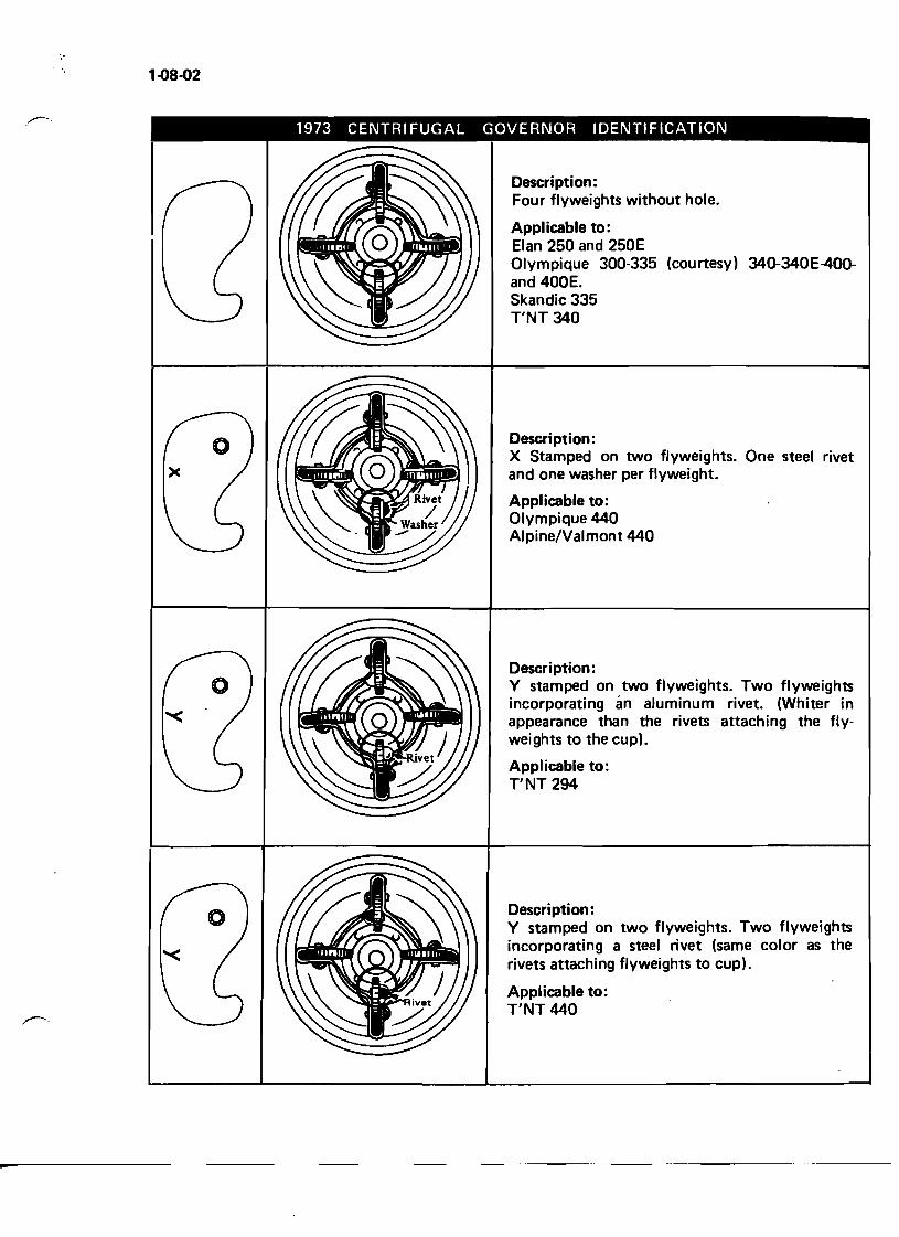
1973 CENTRI FUGAL GOVERNOR IDENTIFICATION
Description: Four flyweights without hole.
Applicable to: Elan 250 and 250E Olympique 300-335 (courtesy) 34Q-340E-40Qand 400E. Skandic 335 T'NT 340
Description: X Stamped on two flyweights. One steel rivet and one washer per flyweight.
Applicable to: Olympique 440 Alpine/Valmont 440
Description: Y stamped on two flyweights. Two flyweights incorporating an aluminum rivet. (Whiter in appearance than the rivets attaching the flyweights to the cup).
Appl icable to: T'NT 294
-
Description: Y stamped on two flyweights. Two flyweights incorporating a steel rivet (same color as the rivets attaching flyweights to cup).
Applicable to: T'NT 440
• •
1-08-03
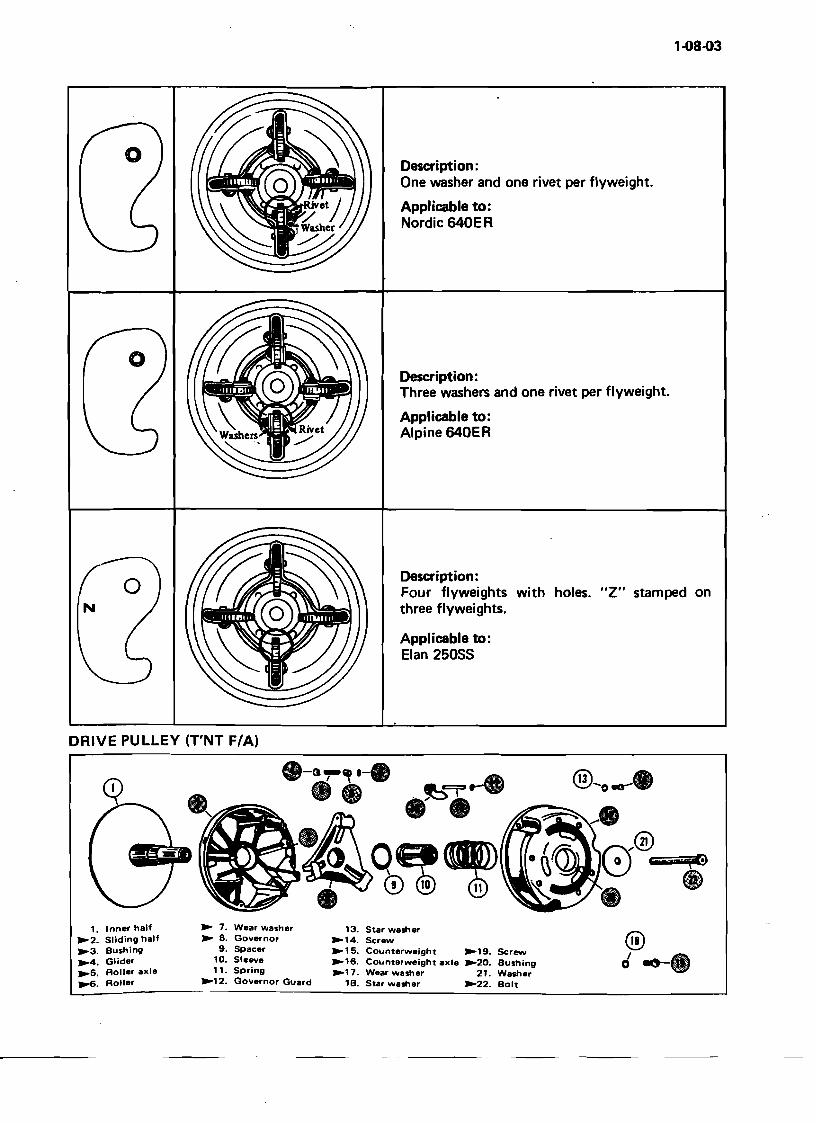
Description: One washer and one rivet per flyweight.
Applicable to: Nordic 640E R
Description: Three washers and one rivet per flyweight.
Applicable to: Alpine 640ER
Description: Four flyweights with holes. "Z" stamped on three flyweights.
Applicable to: Elan 25055
DRIVE PULLEY (T'NT F/A)
.-(1.,.' .-. . @-o.-.ct.- ~..... •-JJ\Qe«m ~"J0®_E,iiiii"•.,.+iiG@
?-C~~0 ® -® 1. Inner half 13. Star washer
~2. Sliding half ~14. Screw ~3. Bushing ~15. Counterweight ~19. Screw ~4. Glider ~16. Counterweight axle ~20. Bushing ~5. Roller axle ~17. Wear washer 21. Washer ~. Roller 1B. Star washer ~22. Bolt
~ 7. Wear washer ~ 8. Governor
9. Spacer 10. Sleeve 11. Spring
~12. Governor Guard
1-08-04
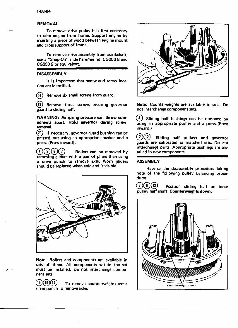
REMOVAL
To remove drive pulley it is first necessary to raise engine from frame. Support engine by inserting a piece of wood between engine mount and cross support of frame.
To remove drive assembly from crankshaft, use a "Snap-On" slide hammer no. CG250 8 and CG250 9 or equivalent.
DISASSEMBLY
It is important that screw and screw location are identified.
® Remove six small screws from guard.
® Remove three screws securing governor guard to sliding half.
WARNING: As spring pressure can throw components apart. Hold governor during screw removal.
@) If necessary, governor guard bushing can be pressed out using an appropriate pusher and a press. (Press inward).
00®CD Rollers can be removed by removing gliders with a pair of pliers then using a drive punch to remove axle. Worn gliders should be replaced when axle end is visible.
-
Note: Rollers and components are available in sets of three. All components within the set must be installed. Do not interchange component sets.
@@@ To remove counterweights use a drive punch to remove axles.
Note: Counterweights are available in sets. Do not interchange component sets.
CD Sliding half bushings can be removed by using an appropriate pusher and a press. (Press inward.)
0® Sliding half pulleys and governor guards are calibrated as matched sets. Do ;'"Ilt interchange parts. Appropriate bushings are installed in new components.
ASSEMBLY
Reverse the disassembly procedure taking note of the following pulley balancing procedures.
00® Position sliding half on inner pulley half shaft. Counterweights down.
CountsrwsOight down
1-08-05
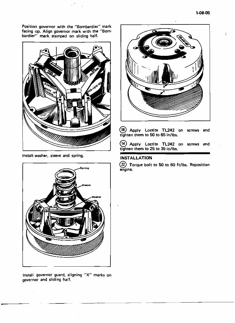
Install washer, sleeve and spring.
Position governor with the "Bombardier" mark facing up. Align governor mark with the "Bombardier" mark stamped on sliding half.
® Apply Loetite TL242 on screws and tighten them to 50 to 65 in/lbs.
® Apply Loctite TL242 on screws and tighten them to 25 to 35 ir:'/Ibs.
INSTALLATION ,
@ Torque bolt to 50 to 60 ft/lbs. Reposition engine.
Install governor guard, aligning "x" marks on governor and sliding half.
-
1-9
1-09-01
Transmission" DRIVEN PULLEY
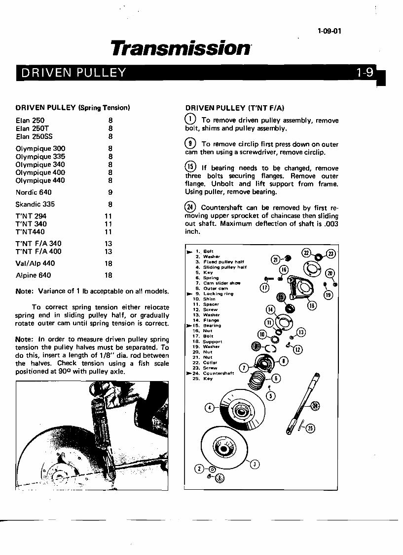
DRIVEN PULLEY (Spring Tension) DRIVEN PULLEY (T'NT F/A)
Elan 250 8 CD To remove driven pulley assembly, remove Elan 250T 8 bolt, shims and pulley assembly. Elan 25055 8 o To remove circlip first press down on outerOlympique 300 8 cam then using a screwdriver, remove circlip. Olympique 335 8 Olympique 340 8 @ If bearing needs to b~ changed, removeOlympique 400 8 three bolts securing flanges. Remove outerOlympique 440 8 flange. Unbolt and Iift support from frame. Nordic 640 9 Using puller, remove bearing.
5kandic 335 8 ® Countershaft can be removed by first reT'NT 294 11 T'NT 340 11 T'NT440 11
T'NT F/A 340 13 T'NT F/A 400 13
Val/Alp 440 18
Alpine 640 18
Note: Variance of 1 Ib acceptable on all models.
To correct spring tension either relocate spring end in sliding pulley half, or gradually rotate outer cam until spring tension is correct.
Note: In order to measure driven pulley spring tension the pulley halves must be separated. To do this, insert a length of 1/8" dia. rod between the halves. Check tension using a fish scale positioned at 900 with pulley axle.
-
. -._-_ ... _--_. ----"""&--------'
moving upper sprocket of chaincase then sliding out shaft. Maximum deflection of shaft is .003 inch.
~ 1.. Bolt @~. 2. Washer @ ...
21. -.. 3. Fixed pulley half ~
:: ~I~~lng pulley half ~ ~m~ ,(20) 6. Spring --r- _ ~
7. Cam slider shae ® s 8. Outer cam 17 \
~1~: ~~~ingring @4~· @B@ 11. Spacer 12. Screw
13. Washer ~ 14. Flange@1
~ 15. Bearing
16. Nut@O.@ 17. Bolt "'0 0 18. Support a A
19. Washer .-c'" fi,)'Yf2\20. Nut .i ~
21. Nut ~ID\ 22. Collar 7 \!; 23. Screw
~24. Countershaft .~
25. Key .- ~~0
CD
1·10-01
Transmission· PULLEY ALIGNMENT 1-101
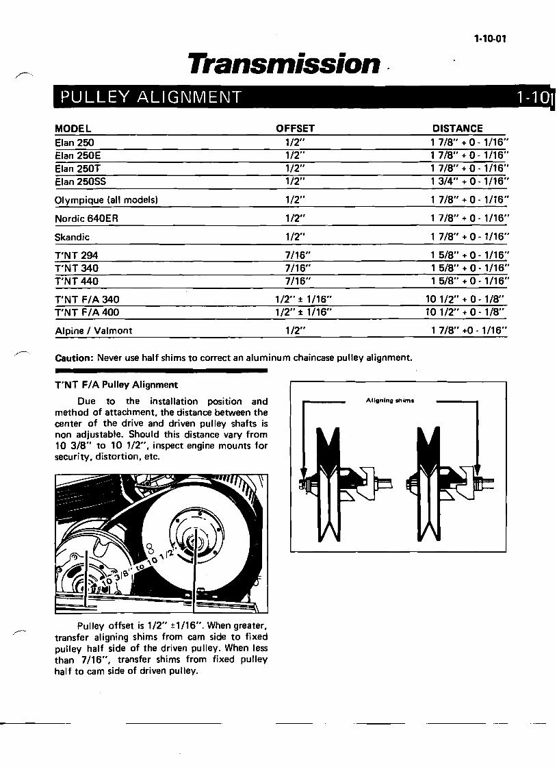
MODEL OFFSET DISTANCE
Elan 250 1/2" 1 7/8" + o· 1/16" Elan 250E 1/2" 1 7/8" + 0 - 1/16" Elan 250T 1/2" 1 7/8" + O· 1/16" Elan 250SS 1/2" 1 3/4" + 0 - 1/16"
Olympique (all models) 1/2" 1 7/8" + 0 - 1/16"
Nordic 640ER 1/2" 1 718" + 0 - 1/16"
Skandic 1/2" 1 7/8" + 0 - 1/16"
T'NT 294 7116" 1 5/8" + 0 - 1/16" T'NT 340 7/16" 1 5/8" + 0 - 1/16" T'NT 440 7116" 15/8" +0-1/16"
T'NT F/A 340 1/2" ± 1/16" 10 1/2" + 0 - 1/8" T'NT F/A400 1/2" ± 1/16" 10 1/2" + 0 - 1/8"
Alpine / Valmont 1/2" 1 7/8" +0 - 1/16"
Caution: Never use half shims to correct an aluminum chaincase pulley alignment.
T'NT F/A Pulley Alignment
Aligning shimsDue to the installation position and method of attachment, the distance between the center of the drive and driven pulley shafts is non adjustable. Should this distance vary from 10 3/8" to 10 1/2", inspect engine mounts for security, distortion, etc.
Pulley offset is 1/2" ±1/16". When greater, transfer aligning shims from cam side to fixed pulley half side of the driven pulley. When less than 7/16", transfer shims from fixed pulley half to cam side of driven pulley.
1-11
1-11-01
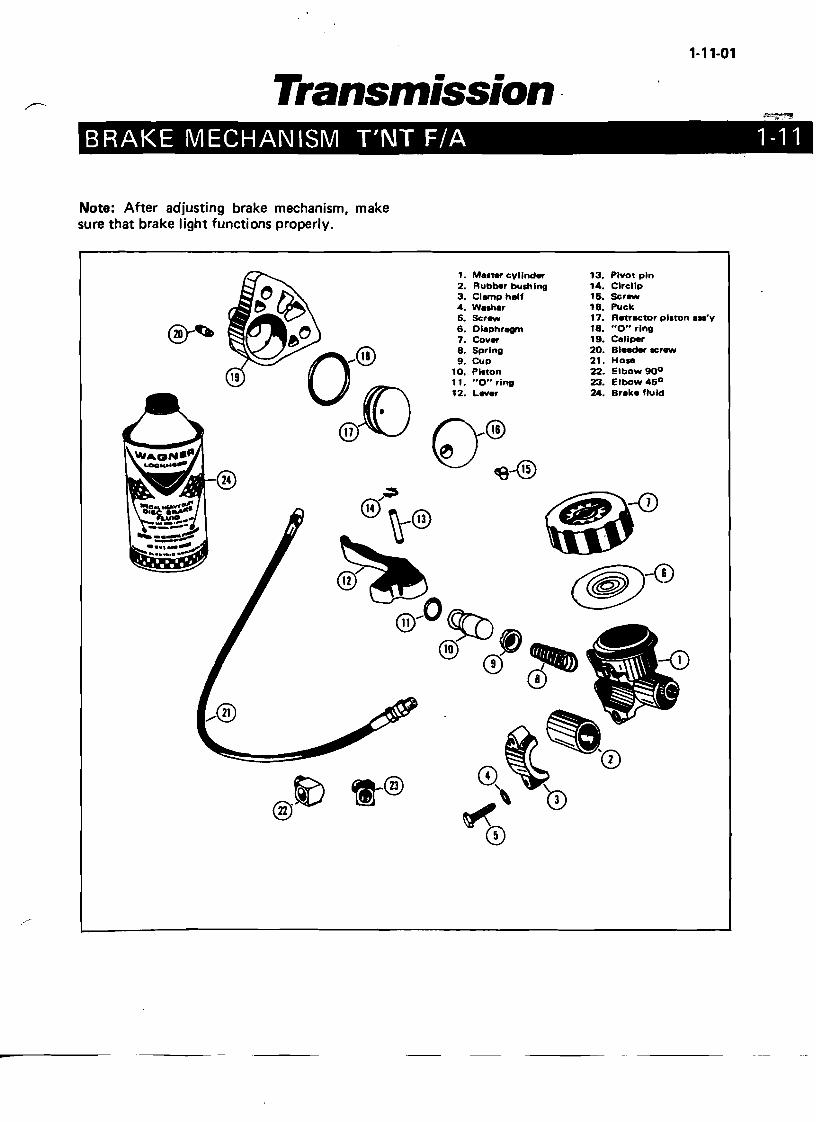
Transmission· BRAKE MECHANISM T'NT F/A
Note: After adjusting brake mechanism, make sure that brake light functions properly.
13. Pivot pin 14. Clrcllp 15. $cr_ 18. Puck 17. Retractor piston ••'y 18. "0" ring 19. Cellper 20. Bleeder scr_ 21. Hose 22. Elbow 900
23. Elbow 450
24. Breke fluid
®
1·11-Cl2
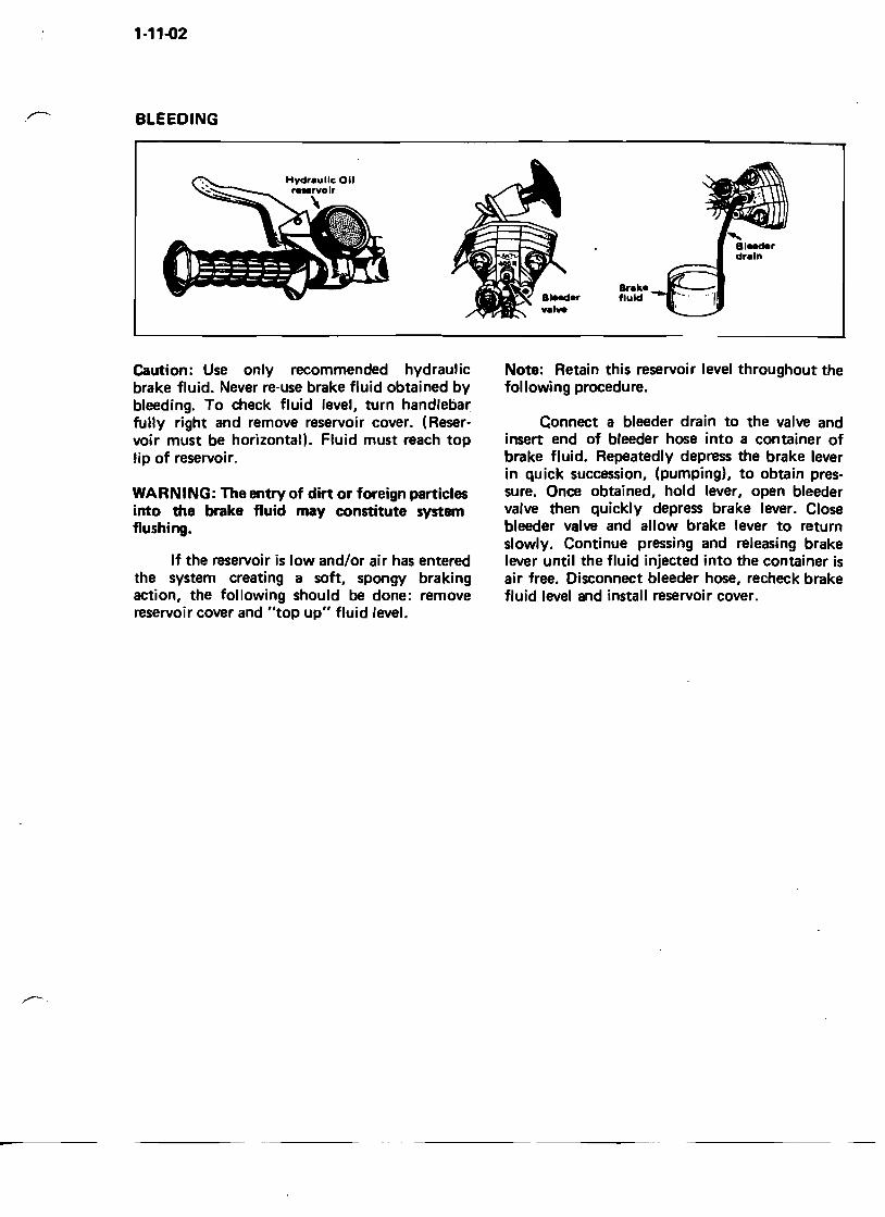
BLEEDING
Caution: Use only recommended hydraulic brake fluid. Never re-use brake fluid obtained by bleeding. To check fluid level, turn handlebar fully right and remove reservoir cover. (Reservoir must be horizontal). Fluid must reach top lip of reservoir.
WARNING: The entry of dirt or foreign particles into the brake fluid may constitute system flushing.
If the reservoir is low and/or air has entered the system creating a soft, spongy braking action, the following should be done: remove reservoir cover and "top up" fluid level.
Note: Retain this reservoir level throughout the following procedure.
Connect a bleeder drain to the valve and insert end of bleeder hose into a container of brake fluid. Repeatedly depress the brake lever in quick succession, (pumping), to obtain pressure. Once obtained, hold lever, open bleeder valve then quickly depress brake lever. Close bleeder valve and allow brake lever to return slowly. Continue pressing and releasing brake lever until the fluid injected into the container is air free. Disconnect bleeder hose, recheck brake fluid level and install reservoir cover.
1-12-01
Transmission CHAINCASE 1
o
• o CD O~ ,
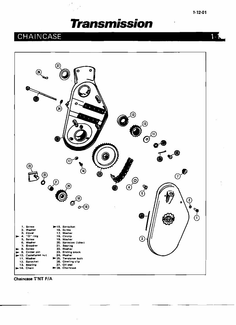
CD 1. SC:rew ~15. Sprocket 2. Washer 16. Screw 3. Cover 17. Washer
~ 4. "0" ring 18. Circlip 5. Screw 19. Washar 6. Washer 20. Sprocket (idler) 7. Breather 21. Bearing
~ 8. Screw 22. Washer ~ 9. Cotter pin 23. Sliding block ~ 1O. Castellated nut 24. Washer
11. Washer ~ 25. Tensioner bolt 12. Sprocket 26. COWling clip 13. Bearing 27. Oil seel
~14. Chain ~ 28. Chaincase
Chaincase T'NT F/A
1·12-02
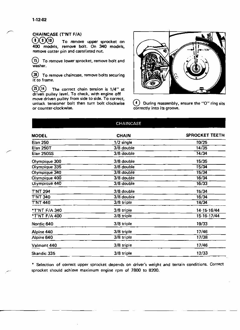
CHAINCASE (T'NT F/A)
CD~ To remove upper sprocket on 400 models, remove bolt. On 340 models, remove cotter pin and castelleted nut.
® To remove lower sprocket, remove bolt and washer.
@ To remove chaincase, remove bolts securing it to frame.
®® The correct chain tension is 1/4" at driven pulley level. To check, with engine off move driven pulley from side to side. To correct, unlock tensioner bolt then turn bolt clockwise or counter-elockwise.
CHAINCASE
MODEL CHAIN SPROCKET TEETH
Elan 250 1/2 single 10/25 Elan 250T 3/8 double 14/35
,---Elan 25055 3/8 double 14/34
Olympique 300 3/8 double 15/35 Olympique 335 3/8 double 15/34 Olympique 340 3/8 double 15/34 Olympique 400 3/8 double 16/34 Ulympique 440 3/8 double 16/33
T'NT 294 3/8 double 15/34 T'NT 340 3/8 double 16/34 T'NT 440 3/8 triple 18/34
*T'NT F/A 340 3/8 triple 14-15-16/44 *T'NT F/A 400 3/8 triple 15-16-17/44
Nordic 640 3/8 triple 19/33
Alpine 440 3/8 triple 17/46 Alpine 640 3/8 triple 17/38
Valmont 440 3/8 triple 17/46
12/33Skandic 335 3/8 triple
* Selection of correct upper sprocket depends on driver's weight and terrain conditions. Correct
~ .. sprocket should achieve maximum engine rpm of 7800 to 8200.
13) During reassembly, ensure the "0" ring sits correctly into its groove.
1-13-01
Transmission GEAR BOX (Alpine and Valmont) 1-13-1
12
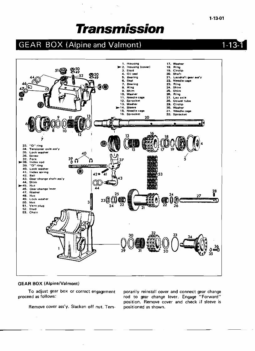
1. Housing 17. Wesher .- 2. Housing (cover) 18. Ring
3. Stud 19. Circlip 4. Oil seal 20. Shaft 5. Bearing 21. Layshaft gear als'y 6. Seal 22. Needle cage 7. Bearing 23. Ring 8. Ring 24. Shim 9. Shim 25. Shim
10. Weiher 26. Ring 11. Needle cage 27. Leya"le 12. Sprocket 28. Dowe' tube 13. Washer 29. Clrclip
'-14. Sleeve 30. Washer 15. Needle cage 31. Needle cage
13 16. Sprocket 20 32. SprocketoC--~~[!!!!!!!!!!!!'!'~.!!!!!!!!!!!!'!'!!!!!!!!!!!!'!'.. !!!!!!!!!!!!!!!~~
, 7
33. "0" ring _I' r. ~WOf7L\. ~)434. Tensioner axle ass'y lS ~ 19 ~~tl! 35. Lock washer 36. Screw 37. Fork
'-38. Inde" rod 16 _,~7 17
{39. "0" ring 40. Lock washer 41. Inde" spring
S342. Ball ., 1;;~4343. Gear change shaft ass'y 44. Shim
'-45. Nut 4446. Gear change lever 47. Washer 2848. Nut 49. Lock washer 50. Nut 51. Vent plug 52. Stud 53. Chain
36 \)1lIII(O 3S
247m e~O@)e:C==2=!O.4Q
22 26
GEAR BOX (Alpine/Valmont)
To adjust gear box or correct engagement porarily reinstall cover and connect gear change proceed as follows: rod to gear change lever. Engage "Forward"
position. Remove cover and check if sleeve is Remove cover ass'y. Slacken off nut. Tem- positioned as shown.
1-13-02
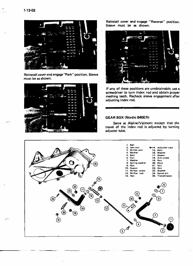
Reinstall cover and engage "Reverse" position. Sleeve must be as shown.
If any of these positions are unobtainable, use a screwdriver to turn index rod and obtain proper meshing teeth. Recheck sleeve engagement after adjusting index rod.
GEAR BOX (Nordic 640E R)
.------ Same as Alpine/Valmont except that the travel of the index rod is adjusted by turning adjuster tube.
Reinstall cover and engage "Park" position. Sleeve must be as shown.
1. Ball 2. Jam nut ~14. Adjuster tube 3. Shifter arm 15. Bolt 4. Washer 16. Washer 5. Bolt 17. Sleeve 6. Nut lB. Arm plate 7. Washer 19. Nut 8. Spring washer 20. Stud 9. Nut 21. Nut
10. Spacer 22. Nut 11. Shifter plate 23. Washer 12. Shifter rod 24. Spiral pin 13. Nut 25. Transmission
® /CD
1-15-01
Steering& Sk.iSystem
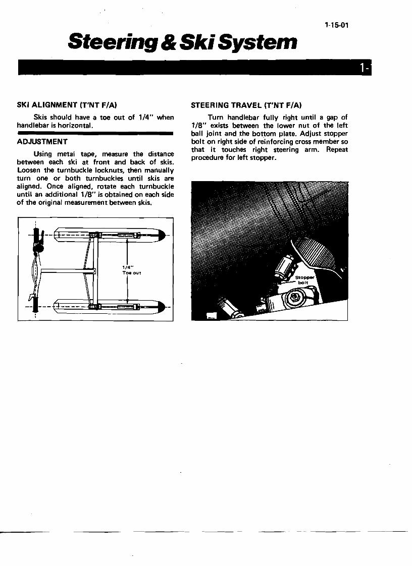
SKI ALIGNMENT (T'NT F/A)
Skis should have a toe out of 1/4" when handlebar is horizontal.
ADJUSTMENT
Using metal tape, measure the distance between each ski at front and back of skis. Loosen the turnbuckle locknuts, then manually turn one or both turnbuckles until skis are aligned. Once aligned, rotate each turnbuckle until an additional 1/8" is obtained on each side of the original measurement between skis.
1/4" Toe out
STEERING TRAVEL (T'NT F/A)
Turn handlebar fully right until a gap of 1/8" exists between the lower nut of the left ball joint and the bottom plate. Adjust stopper bolt on right side of reinforcing cross member so that it touches right steering arm. Repeat procedure for left stopper.
1-15-02
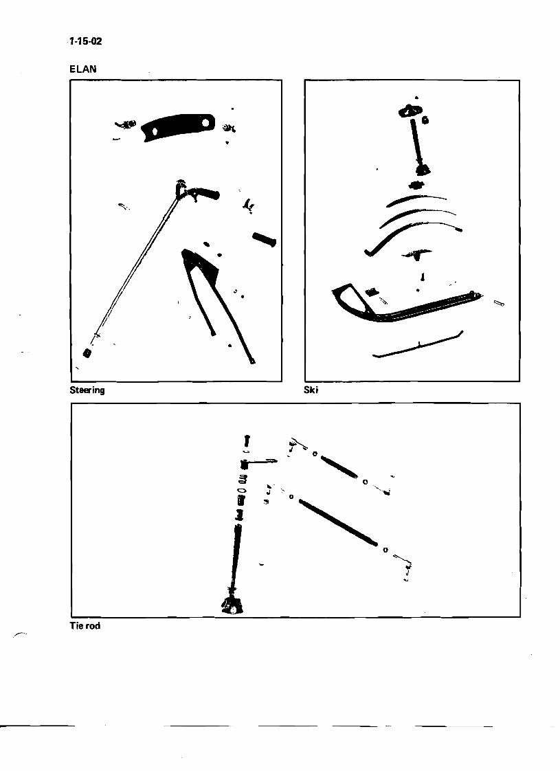
ELAN
•
-
I •
{
~
Steering Ski
Tie rod
1-15-03
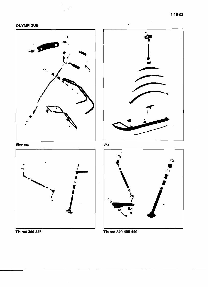
OLYMPIQUE
, ..•1 •
.-r I
• .. 8 •')
" ~
Steering Ski
Tie rod 300-335 Tie rod 340-400-440
• , <>
• r
1I
, (.~( •0 ....,
\ •• 0 't\ "t:. .... i
~ '":fI m
1-15-04
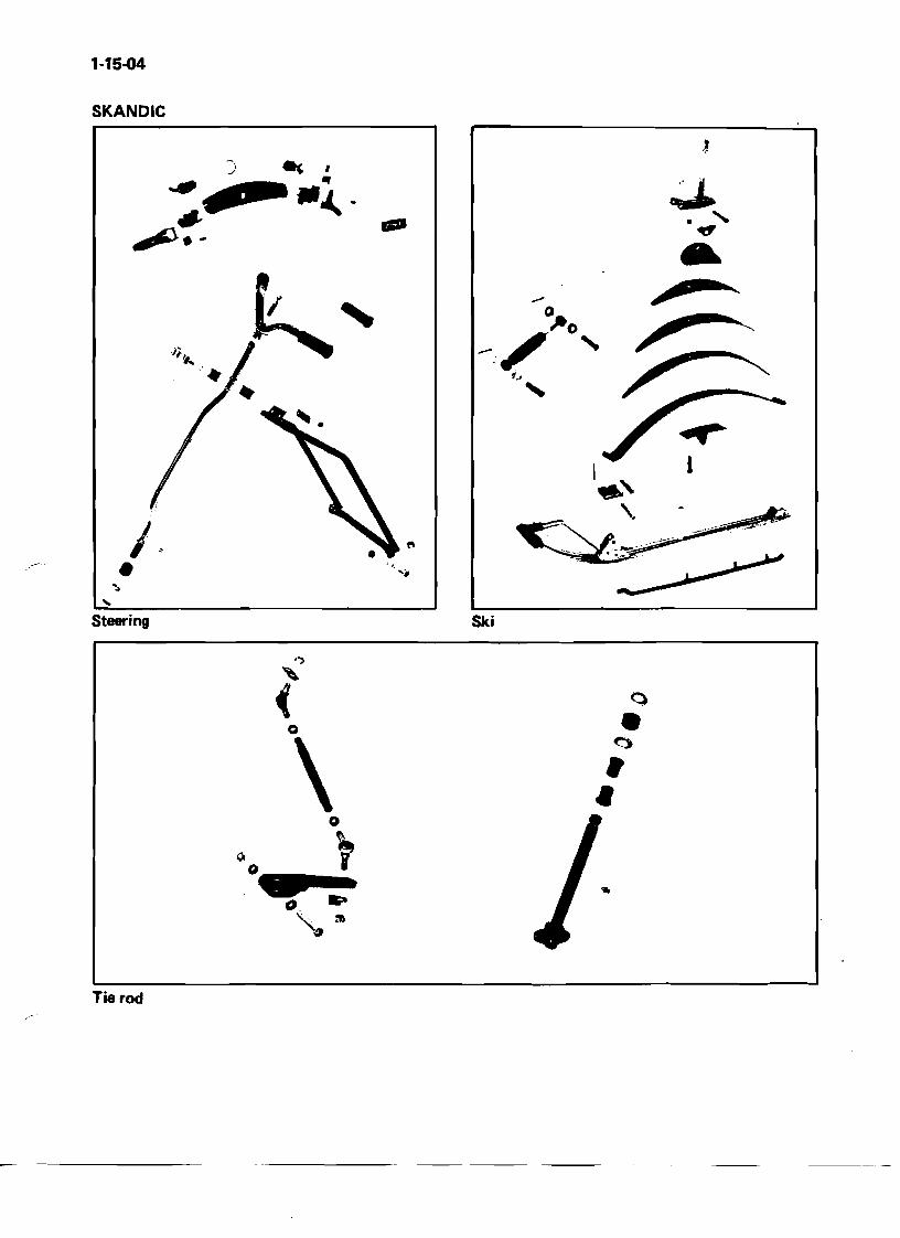
SKANDIC
-
•I~
... Steering Ski
,..,
Q(
\ •••o ~
Tie rod
~-----
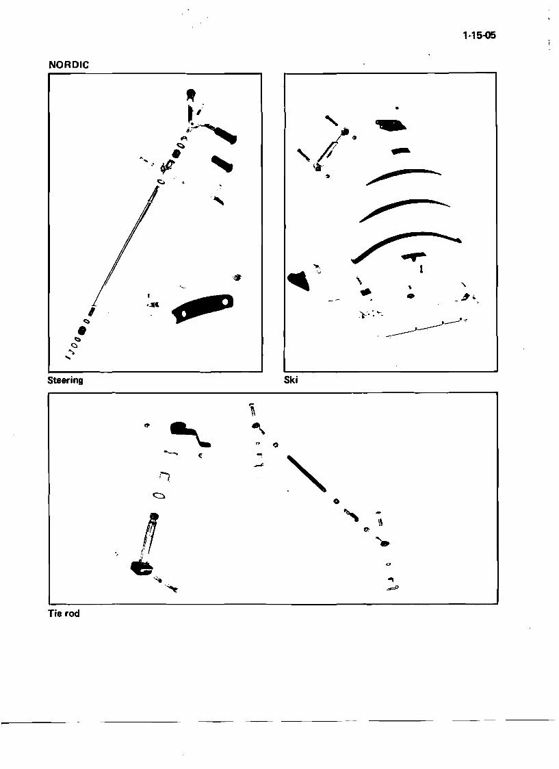
1·15-Q5
NORDIC
•
..,. 1
\
• • -".. , "
..... , Steering Ski
\ ~
I)
""'!
.-.
0 " •.
~~
\\l ••., u
~
~
Tie rod
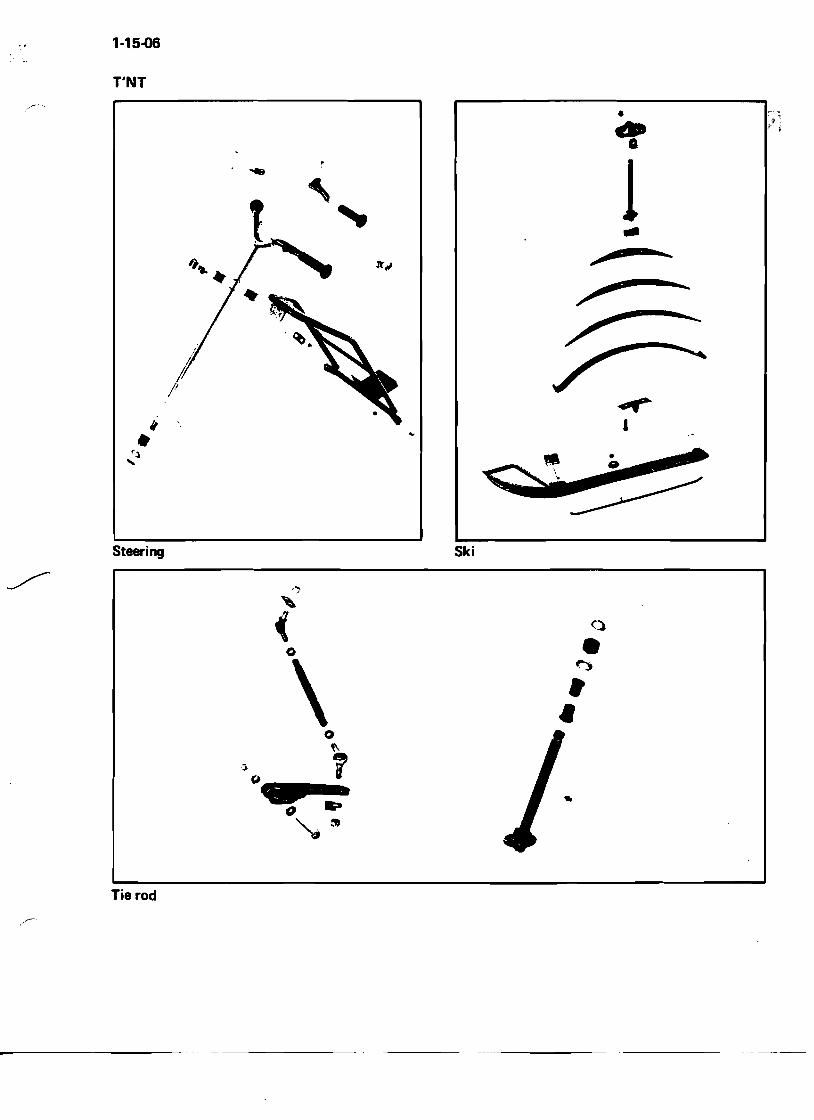
1-15-06
T'NT
"•..~ ....
..
•..• 1..
Steering Ski
"
(" (~
o ~
\ •••
Tie rod
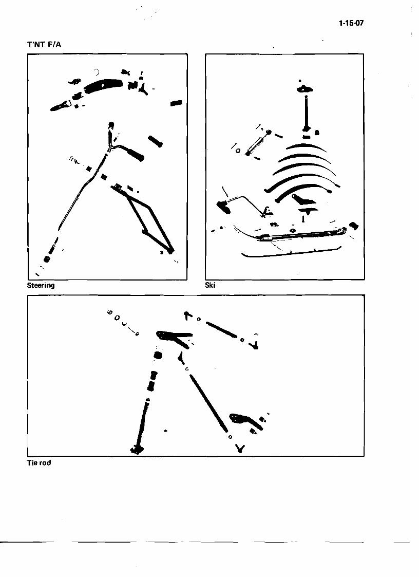
1·15-07
T'NT F/A
• ~ -
...... \., .. ~ .
-:C_- --
.... ..'
"
1.-""~-........---~
... I·•
Steering Ski
•
Tie rod
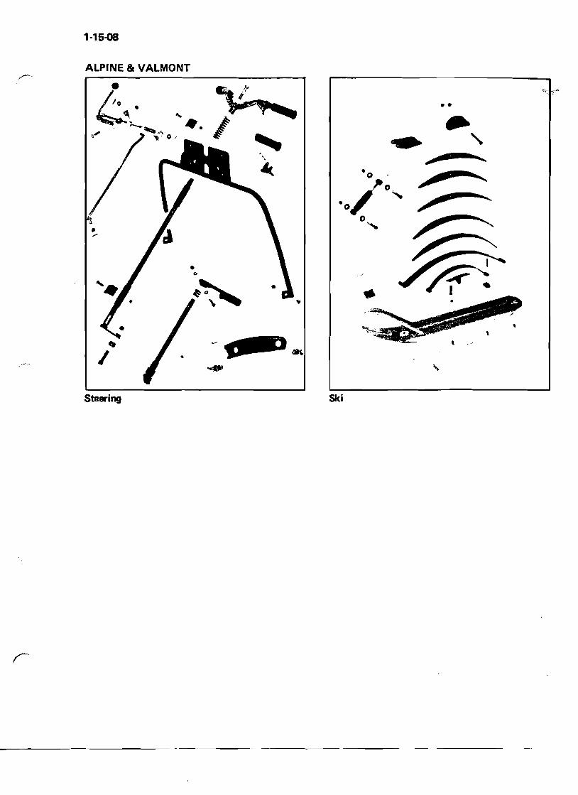
1·15-08
ALPINE & VALMONT
•"
,. I •
~-" ... • •
••
, Steering Ski
1-15-09
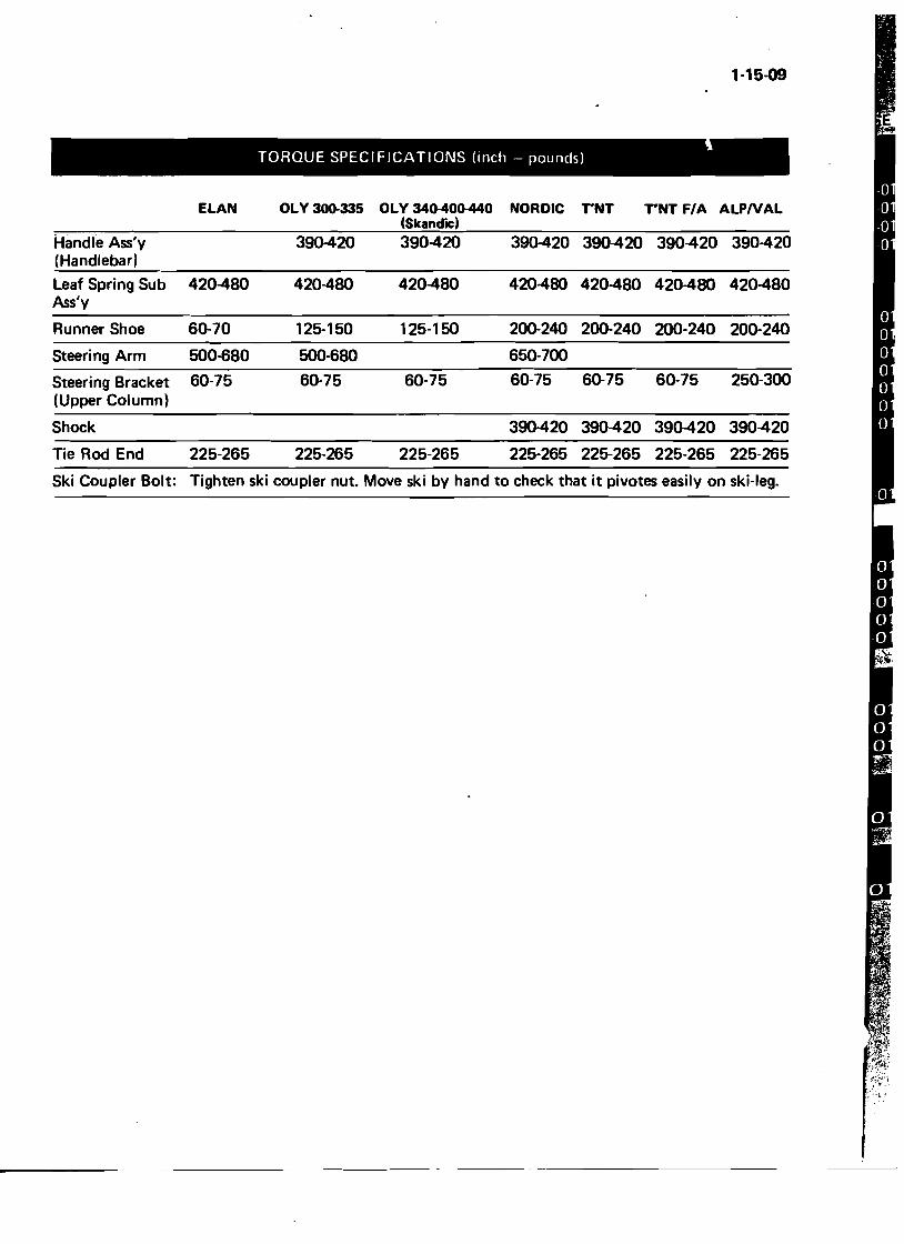
TORQUE SPECIFICATIONS (inch - pounds)
ELAN OLY 300-335 OLY 340-400440 NORDIC TNT TNT F/A ALPNAL (Skandic)
Handle Ass'y 390-420 390-420 390-420 390-420 390-420 390-420 (Handlebar)
Leaf Spring Sub 420-480 420-480 420-480 420-480 420-480 420-480 420-480 Ass'y
Runner Shoe 60-70 125-150 125-150 200-240 200-240 200-240 200-240
Steering Arm 500-680 500-680 650-700
Steering Bracket 60-75 60·75 60-75 60-75 60-75 60-75 250-300 (Upper Column)
Shock 390-420 390-420 390-420 390-420
Tie Rod End 225-265 225-265 225-265 225-265 225-265 225-265 225·265
Ski Coupler Bolt: Tighten ski coupler nut. Move ski by hand to check that it pivotes easily on ski-leg.
ENGINE
Engine - One Cylinder Engine - Two Cylinder Timing Carburetor Cleaning and Inspection
2-02-01
Engine
I®
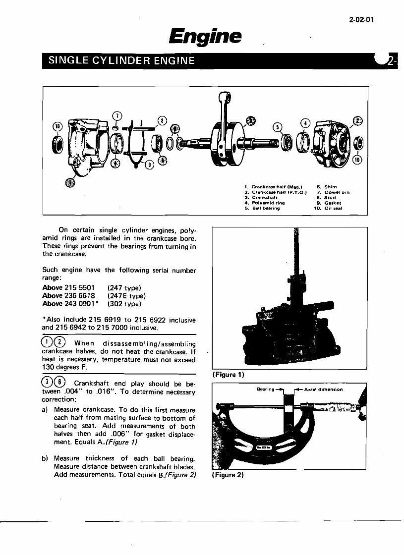
1. Crankcase half (Mag.1 6. Shim 2. Crankcase half (P.T.O.I 7. Oowel pin 3. Crankshaft 8. Stud 4. Polyamid ring 9. Gasket 5. Sail bearing 10. Oil seal
On certain single cylinder engines, polyamid rings are installed in the crankcase bore. These rings prevent the bearings from turning in the crankcase.
Such engi ne have the following serial number range:
Above 215 5501 (247 type) Above 236 6618 (247E type) Above 243 0901 * (302 type)
*Also include 215 6919 to 215 6922 inclusive and 2156942 to 2157000 inclusive.
80 When dissassembling/assembling crankcase halves, do not heat the crankcase. If heat is necessary, temperature must not exceed 130 degrees F.
00 Crankshaft end play should be between .004" to .016". To determine necessary correction;
a) Measure crankcase. To do this first measure each half from mating surface to bottom of bearing seat. Add measurements of both halves then add .006" for gasket displacement. Equals A. (Figure 1)
b) Measure thickness of each ball bearing. Measure distance between crankshaft blades. Add measurements. Total equals B.(Figure 2)
(Figure 1)
Axial dimension
(Figure 2)
2·02-02
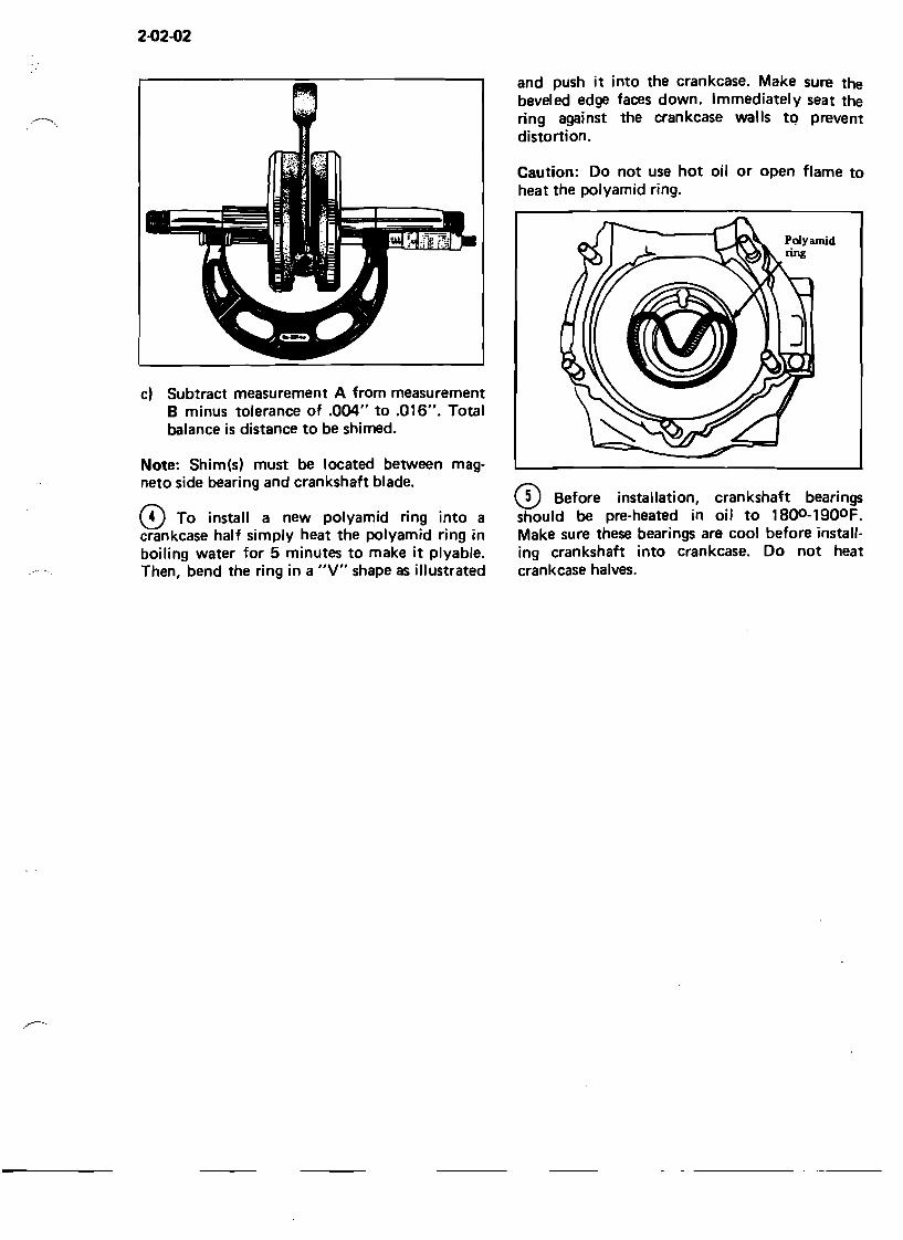
c) Subtract measurement A from measurement B minus tolerance of .004" to .016". Total balance is distance to be shimed.
Note: Shim(s) must be located between magneto side bearing and crankshaft blade.
CD To install a new polyamid ring into a crankcase half simply heat the polyamid ring in boiling water for 5 minutes to make it plyable. Then, bend the ring in a "v" shape as illustrated
and push it into the crankcase. Make sure the beveled edge faces down. Immediately seat the ring against distortion.
the crankcase walls tQ prevent
Caution: Do not use hot oil heat the polyamid ring.
or open flame to
CD Before installation, crankshaft bearings should be pre-heated in oil to 1800 -1900 F. Make sure these bearings are cool before installing crankshaft into crankcase. Do not heat crankcase halves.
2-03-01
Engine TWIN CYLINDER ENGINE
®
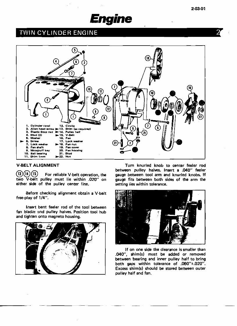
1. Cylinder cowl 12. Circlip 2. Allen head screw .13. Shim Caa required) 3. Elutlc Stop nut .14. Pulley half 4. Stud (2) .15. V-Belt 5. Waaher 18. Fan
• 6. SCr_ 17. Lock waah., 7. Lock weah., .18. Fan nut B. Fan ahaft 19. Fan cover 9. Woodruff key 20. Fan houalng
10. Ball bearing 21. Stud 11. Shim 1mm .22. Nut
V-BELT ALIGNMENT
@@@ For reliable V-belt operation, the two V-belt pulley must lie within .020" on either side of the pulley center line.
Before checking alignment obtain a V-belt free-play of 1/4".
Insert bent feeler rod of the tool between fan blades and pulley halves. Position tool hub and tighten onto m~gneto housing.
Turn knurled knob to center feeler rod between pulley halves. Insert a .040" feeler gauge between tool arm and knurled knobs. If gauge fits between both sides of the arm the setting lies within tolerance.
If on one side the clearance is smaller than .040", shim(s) must be added or removed between bearing and inner pulley half to bring both gaps within tolerance of .060"±.020". Excess shim(s) should be stored between outer pulley half and fan.
2-03-02
® When tightening fan nut use special holder ---', to lock fan in position. Make sure that V-belt
does not get squeeze between pulley halves.
Q)@ When reinstalling a fan, housing retaining nut or screw, use Loctite TL 242 to prevent loosening through vibration.
CYLINDER ALIGNMENT Applicable on: 338, 343, 401, 434, 435,
640.
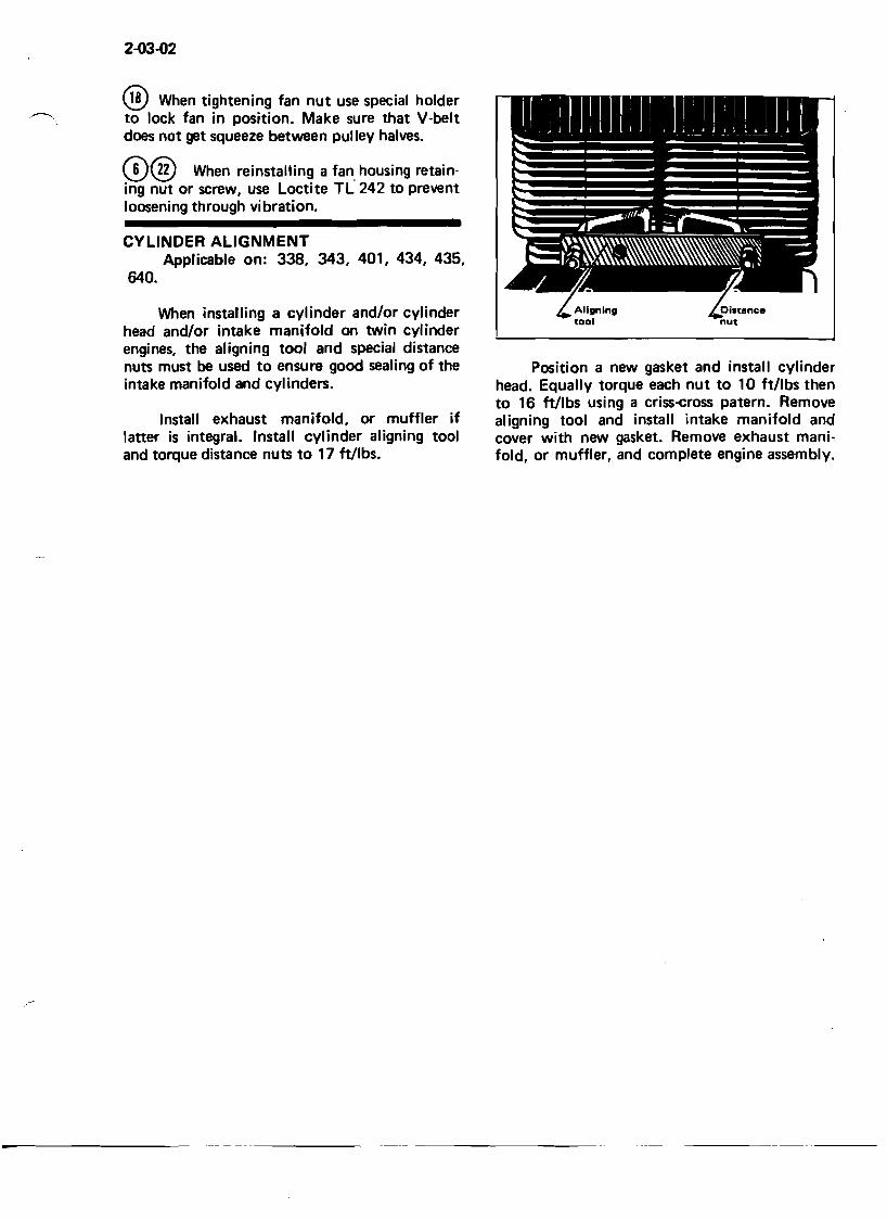
When installing a cylinder and/or cylinder head and/or intake manifold on twin cylinder engines, the aligning tool and special distance nuts must be used to ensure good sealing of the intake manifold and cylinders.
Install exhaust manifold, or muffler if latter is integral. Install cylinder aligning tool and torque distance nuts to 17 ftllbs.
Position a new gasket and install cylinder head. Equally torque each nut to 10 ft/lbs then to 16 ftllbs using a criss-cross paterno Remove aligning tool and install intake manifold and cover with new gasket. Remove exhaust manifold, or muffler, and complete engine assembly.
2-6
2-06-01
Engine ENGINE TIMING
ONE CYLINDER
Engine Type: 247, 302 and 337. Refer to 1973 timing chart for specifications.
TWO CYLINDER
Engine Type: 338, 343, 401,434,435 and 640. Refer to 1973 timing chart for specifications.
Engine Type: 248, 249, 294 and 346. Refer to 1973 timing chart for specifications.
On these engines the advance mechanism is eliminated, therefore, timing and edge gap adjustments are greatly simplified. It is not necessary to hold a centrifugal weight through the magneto plate.
Engine Type: 396
On this particular model, a capacitor discharge (C.D.) ignition system is installed. Unlike conventional systems, plug firing is initiated by an electrical pulse induced in a magnetic pick-up coil. The pulse is released when a metal projection on the flywheel hub rotates past the pick-up.
Equipment required: An approved stroboscopic timing light with
a capacitor or inductor pick-up.
Approved timing lights. Brand Model# Power Requirement*
Sun PTL 45 6/12 volts D.C. Snap-On Tools MT215B 6/12 volts D.C. Bosch EFAW 169 A 6/12 volts D.C.
*Since the vehicles electrical system cannot supply the required lamp voltage an external power source is required.
PROCEDURE
Place skis tips against a wall. Use a support incorporating a protective guard to block vehicle off the ground. (Approx. 6" between track and
floor). Remove rubber plug from upper crankcase half. Connect an operating timing light to magneto side spark plug wire.
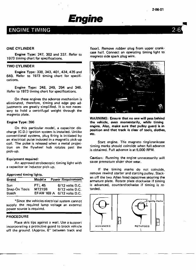
WARNING: Ensure that no one will pass behind the vehicle, even momentarily, while timing engine. Also, make sure that pulley guard is in position and that track is clear of tools, clothes, etc.
Start engine. The magneto ring/crankcase timing marks should coincide when full advance is obtained. Full advance is at 5,000 RPM.
Caution: Running the engine unnecessarily will cause premature slider shoe wear.
If the timing marks do not coincide, remove rewind starter and starting pulley. Slacken off the two Allen head capscrews securing the armature plate. Rotate plate clockwise if timing is advanced, counterclockwise if timing is retarded.
RETARDEDADVANCED \
2-06-02
Once timing is correct on Mag. side, release If timing does not coincide, install a T.D.C. throttle, apply the brake and turn off the gauge into P.T.O. spark plug hole. Scribe true
-""', ignition. Connect timing light to P.T.O. side marks on magneto ring. (.060" BTDC and .080" spark plug- wire. Start engine and check if P.T.O. BTDC). Repeat for other cylinder. Position timing coincides with Mag. side timing. armature plate so that both cylinders fire within
tolerance of .060" to .080".
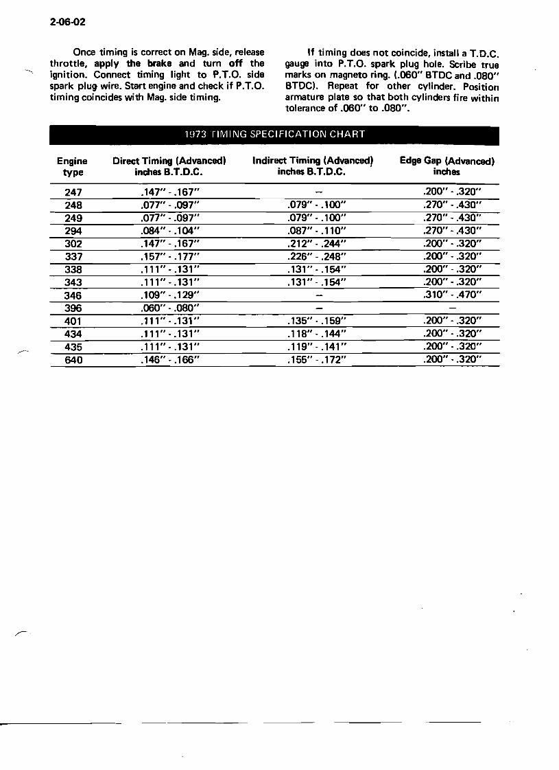
1973 TIIVIING SPECIFICATION CHART
Engine Direct Timing (Advanced) Indirect Timing (Advanced) Edge Gap (Advanced) type inches B.T.D.C. inches B.T.D.C. inches
247 .147" - .167" .200" - .320" 248 .077" - .097" .079" - .100" .270" - .430" 249 .077" - .097" .079" ..100" .270" ..430" 294 .084" ..104" .087" - .110" .270" ..430" 302 .147" - .167" .212" - .244" .200" ..320" 337 .157" - .177" .226" - .248" .200" ..320" 338 .111"-.131" .131" - .154" .200" - .320" 343 .111" - .131" .131" - .154" .200" - .320" 346 .109" - .129" .310" - .470" 396 .060" - .080" 401 .111" - .131" .135" - .159" .200" - .320" 434 .111" - .131" .118"-.144" .200" - .320" 435 .111" - .131" .119" - .141 " .200" - .320"
~~~
640 .146" - .166" .155" - .172" .200" - .320"
I,. ~Engine r·· ..·>
.\.-'-.,
......~.
~-u,·u I
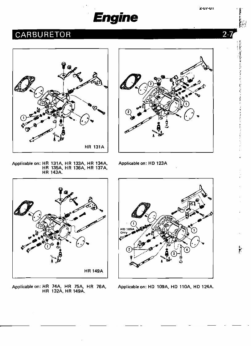
CARBURETOR 2-~
HR 131A
., ! 1
Applicable on: HR 131A, HR 133A, HR 134A, Appl icable on: H0 123A HR 135A, HR 136A, HR 137A, HR 143A.
HR 149A
Applicable on: HR 74A, HR 75A, HR 76A, HR 132A, HR 149A.
Applicable on: HD 109A, HD 110A, HD 124A.
2·07-02
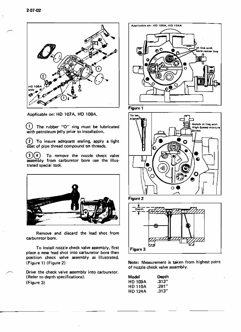
Applicable on: HD 109A. HD 124A
Applicable on: HD 107A, HD 108A.
CD The rubber "0" ring must be lubricated with petroleum jelly prior to installation.
CD To insure adequate sealing, apply a light coat of pipe thread compound on threads.
00 To remove the nozzle check valve assembly from carburetor bore use the illustrated special tool.
Remove and discard the lead shot from carburetor bore.
To install nozzle check valve assembly, first place a new lead shot into carburetor bore then position check valve assembly as illustrated. (Figure 1) (Figure 2)
Drive the check valve assembly into carburetor. .-----(Refer to depth specifications). (Figure 3)
Figure 1
r Figure 2
Figure 3
Note: Measurement is taken from highest point of nozzle check valve assembly.
Mode' Depth HD 109A .313" HD 110A .281 " HD 124A .313"
2-07..Q3
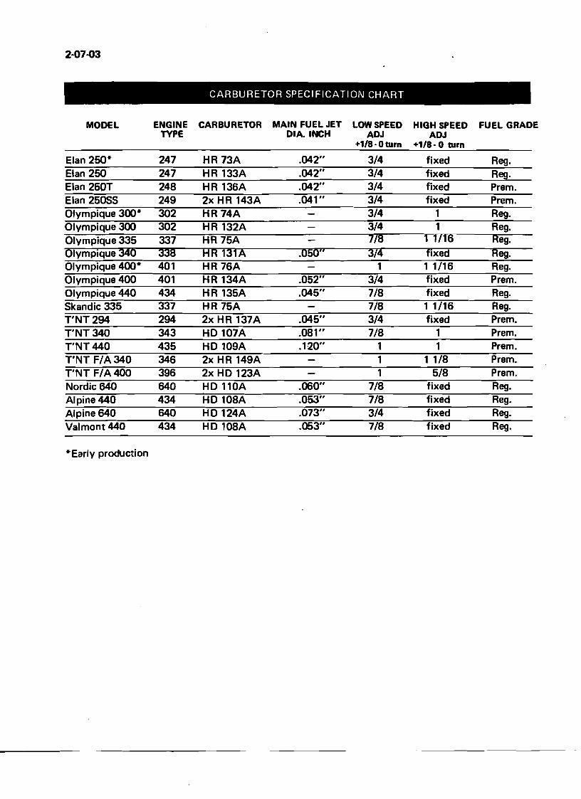
CARBURETOR SPECIFICATION CHART
MODEL ENGINE CARBURETOR MAIN FUEL JET LOW SPEED HIGH SPEED FUEL GRADE TYPE DIA. INCH ADJ ADJ
+1/8·0turn +1/8· 0 turn
Elan 250· 247 HR73A .042" 3/4 fixed Reg. Elan 250 247 HR 133A .042" 3/4 fixed Reg. Elan 250T 248 HR 136A .042" 3/4 fixed Premo Elan 25055 249 2x HR 143A .041 " 3/4 fixed Premo Olympique 300· 302 HR 74A 3/4 1 Reg. Olympique 300 302 HR 132A 3/4 1 Reg. Olympique 335 337 HR 75A 178 1 1716 Reg. Olympique 340 338 HR 131A .050" 374 fixed Reg. Olympique 400· 401 HR 76A 1 1 1/16 Reg. Olympique 400 401 HR 134A .052" 3/4 fixed Premo Olympique 440 434 HR 135A .045" 7/8 fixed Reg. 5kandic 335 337 HR 75A 7/8 1 1/16 Reg. T'NT294 294 2x HR 137A .045" 3/4 fixed Premo T'NT 340 343 HD 107A .081" 7/8 1 Premo T'NT 440 435 HD 109A .120" 1 1 Premo T'NT F/A340 346 2x HR 149A 1 1 1/8 Premo T'NT F/A400 396 2x HD 123A 1 5/8 Premo Nordic 640 640 HD 110A .060" 7/8 fixed Reg. Alpine 440 434 HD 108A .053" 7/8 fixed Reg. Alpine 640 640 HD 124A .073" 3/4 fixed Reg. Valmont440 434 HD 108A .053" 7/8 fixed Reg.
• Early production
2-08-01
Engine CLEANING & INSPECTION 2-8
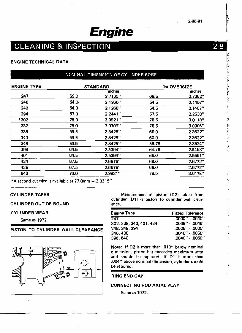
ENGINE TECHNICAL DATA
NOMINAL DIMENSION OF CYLINDER BORE
ENGINE TYPE STANDARD 1st OVERSIZE inches inches
247 69.0 2.7165" 69.5 2.7362" 248 54.0- 2.1260" 54.5 2.1457" 249 54.0 2.1260" 54.5 2.1457" 294 57.0 2.2441 " 57.5 2.2638"
*302 76.0 2.9921 " 76.5 3.0118" 337 78.0 3.0709" 78.5 3.0906" .i~338 59.5 2.3425" 60.0 2.3622" ;.
!
343 59.5 2.3425" 60.0 2.3622" 346 59.5 2.3425" 59.75 2.3524" ,
396 64.5 2.5394" 64.75 2.5493" I
401 64.5 2.5394" 65.0 2.5591 " 434 67.5 2.6575" 68.0 2.6772" 435 67.5 2.6575" 68.0 2.6772" 640 76.0 2.9921 " 76.5 3.0118"
* A second oversize is available at 77.0mm - 3.0315"
CYLINDER TAPER Measurement of piston (02) taken from cylinder (01) is piston to cylinder wall clear
CYLINDER OUT OF ROUND ance.
CYLINDER WEAR Engine Type Fitted Tolerance ~:--------:..:....._-----~==-o::":"":'':'':
.0030" - .0040" Same as 1972. 247 302,338,343,401,434 .0035" - .0045"
.0025" - .0035" PISTON TO CYLINDER WALL CLEARANCE 248,249,294 346,435 .0045" - .0055" r.,396,640 .0040" - .0050"
Note: If 02 is more than .010" below nominal dimension, piston has exceeded maximum wear and should be replaced. If 01 is more than .004" above nominal dimension, cylinder should be rebored.
RING END GAP
CONNECTING ROD AXIAL PLAY
Same as 1972.
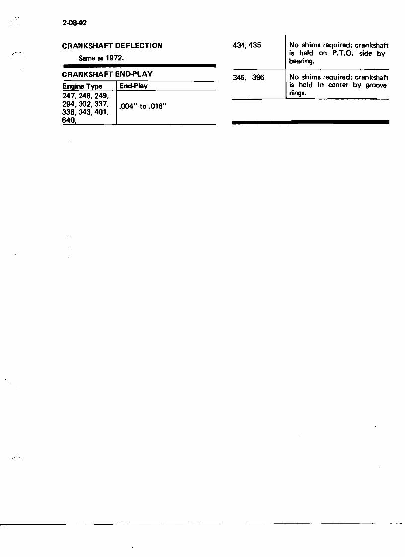
2-08-02
CRANKSHAFT DEFLECTION 434,435
Same as 1972.
CRANKSHAFTEND~LAY 346, 396 Engine Type End~lay
247,248,249, 294,302, 337, .004" to .016" 338,343,401, 640,
No shims required; crankshaft is held on P.T.D. side by bearing.
No shims required; crankshaft is held in center by groove rings.
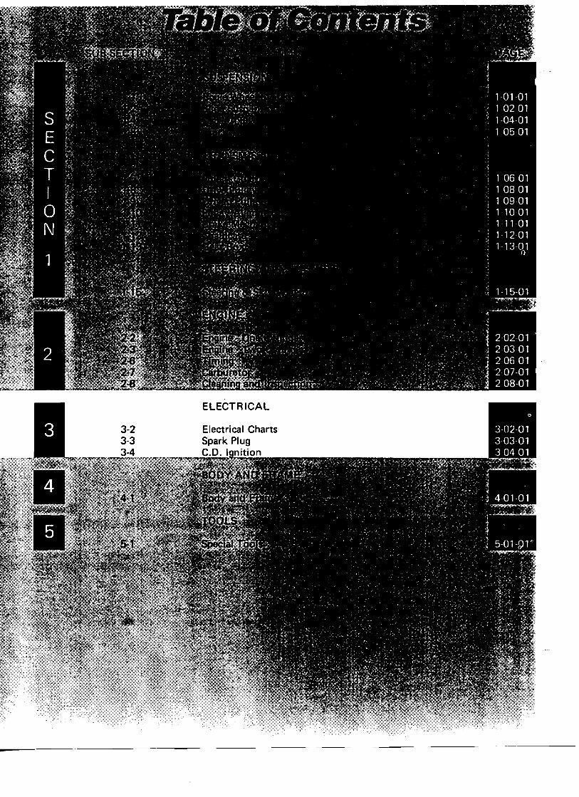
ELECTRICAL
Electrical Charts Spark Plug C.D. I nition
-
3-02-01
Electrical•. ELECTRICAL CHARTS 3
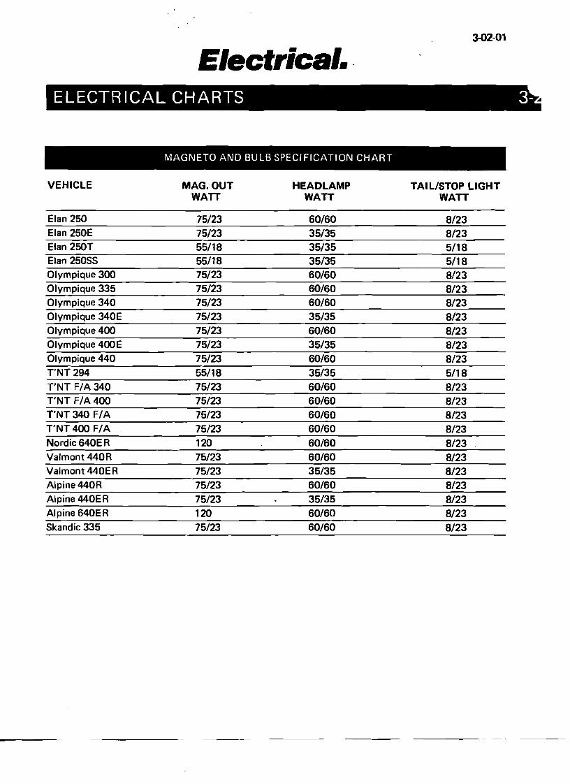
MAGNETO AND BULB SPECIFICATION CHART
VEHICLE MAG. OUT HEADLAMP TAIL/STOP LIGHT WAIT WATT WATT
Elan 250 75/23 60/60 8/23 Elan 250E 75/23 35/35 8/23 Elan 250T 55/18 35/35 5/18 Elan 25055 55/18 35/35 5/18 Olympique 300 75/23 60/60 8/23 Olympique 335 75/23 60/60 8/23 Olympique 340 75/23 60/60 8/23 Olympique 340E 75/23 35/35 8/23 Olympique 400 75/23 60/60 8/23 Olympique 400E 75/23 35/35 8/23 Olympique 440 75/23 60/60 8/23 T'NT 294 55/18 35/35 5/18 T'I\JT F/A 340 75/23 60/60 8/23 T'NT F/A 400 75/23 60/60 8/23 T'NT 340 F/A 75/23 60/60 8/23 T'NT 400 F/A 75/23 60/60 8/23 Nordic 640E R 120 60/60 8/23 Va/mont 440R 75/23 60/60 8/23 Valmont 440ER 75/23 35/35 8/23 Alpine440R 75/23 60/60 8/23 Alpine 440ER 75/23 35/35 8/23 Alpine 640ER 120 60/60 8/23 5kandic 335 75/23 60/60 8/23
----
') )
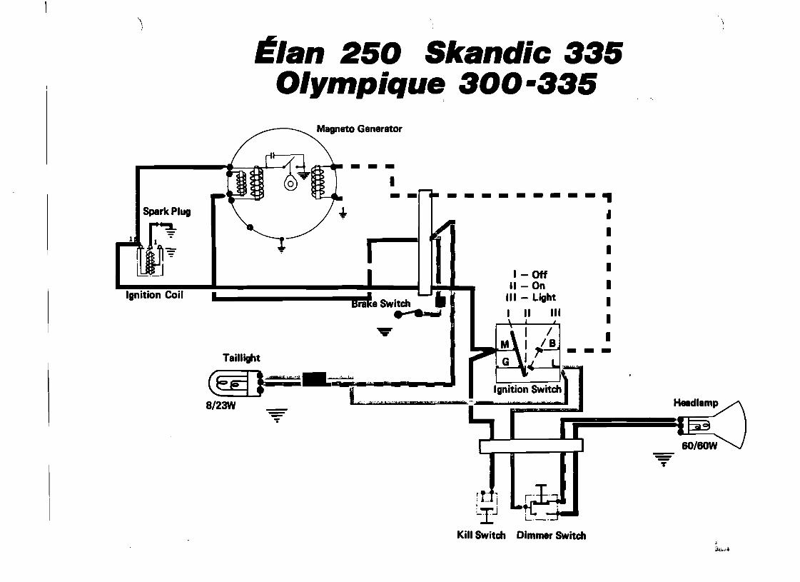
Elan 250 Skandic 335 O/ympique 300-335
Magneto Generator
...tt"--I
Spark Plug .. I I
Ignition Coil I I L-I.LBra e Switch •
... ~
Taillight
@)=.•.."......-,- '
-----~• I I
I-Off I II - On I
III - Light I I II III I
till - ..L\: ,t~ - -
I
I -
.. ,, I...... C\'" CbF"O'Ui!!"_""'''"= _8/23W ~
T
---T
r·t-J~: -,- I
~Ij
Kill Switch Dimmer Switch ,i ili."",,~
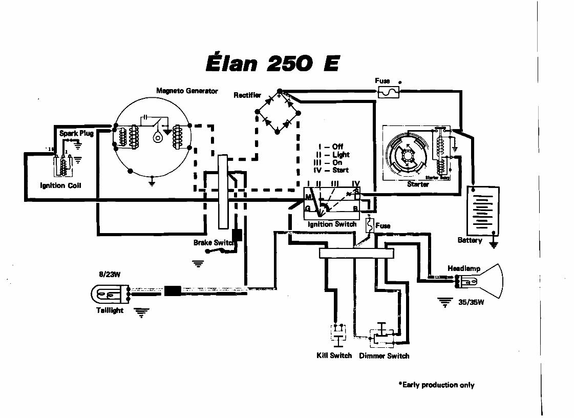
Elan 250 E Fu••
Magneto Generator r--
Spark Plug I . 1
m I I I
I
• . .. ... ... - ~ 1 J
• I
I Ignition Coli
•--• ;:oJIr--i:i-------I
---------I-......-_i U··-
-Batt..y-:~~
8/2M
F -,- ,~ _:_~,-' '.- -, '_ , __ .-.~.
~ 36/36W
~ffi-·~··_·_H_.-_'-'---' -_., or
Taillight -=or
;rt·"~ ....1 I
~Ij
Kill Switch Dimmer Switch
"Early production only
I I I.
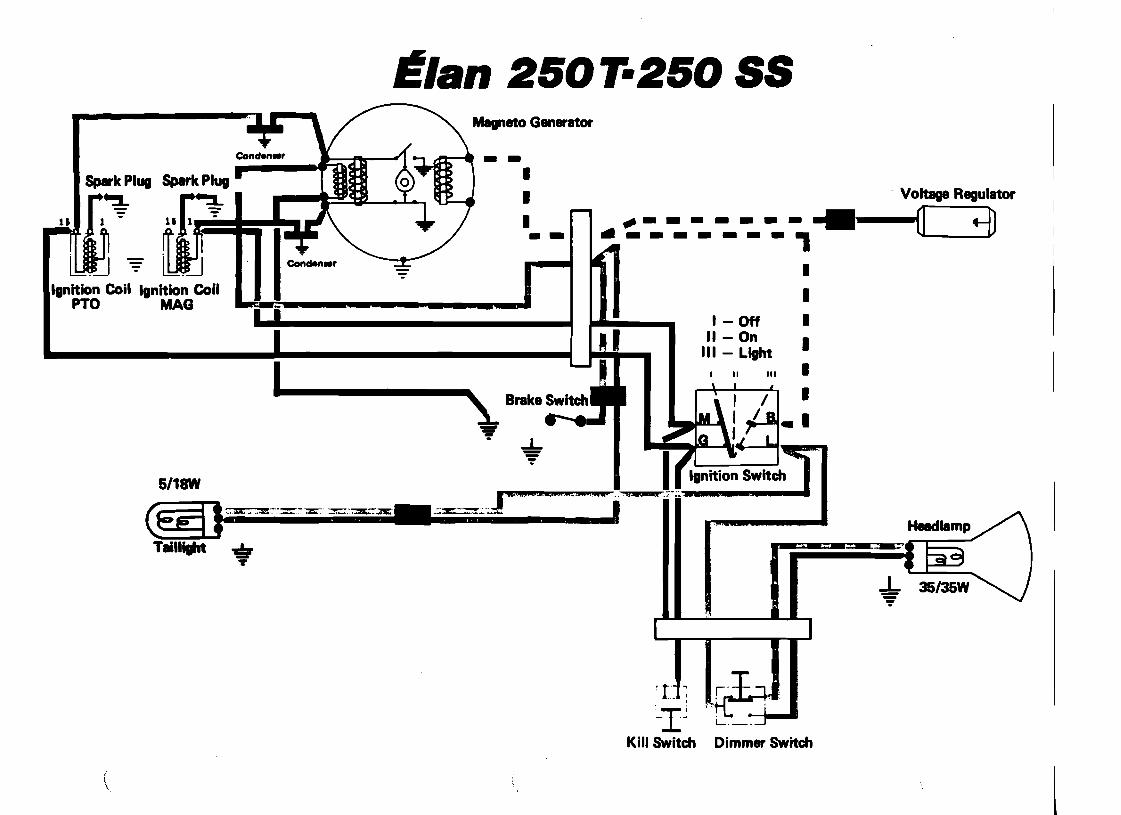
Magneto Generator
--
I m ~ m Ignition Coil Ignition Coil
PTO MAG
Itlan 250T-250 55
. Voltage Regulator
.",--------- G +=0._------, I - Off
II - On III - Light
I II III
6/18W I iii3'l..: ._--_ .. --_. _ .. ..__....J ".MGihU:;;..4.,_i!.."o I" -
1_~-='..._&_=-_!__-.l.
Ct!fL.J*~--=- -=: . _.~.2I:: •.••z;;::=_•. _.... . ,
TeilliIht .. II I r: ,- -=--~'~ ~
+ ~I]:
~I~ Kill Switch Dimmer Switch
(
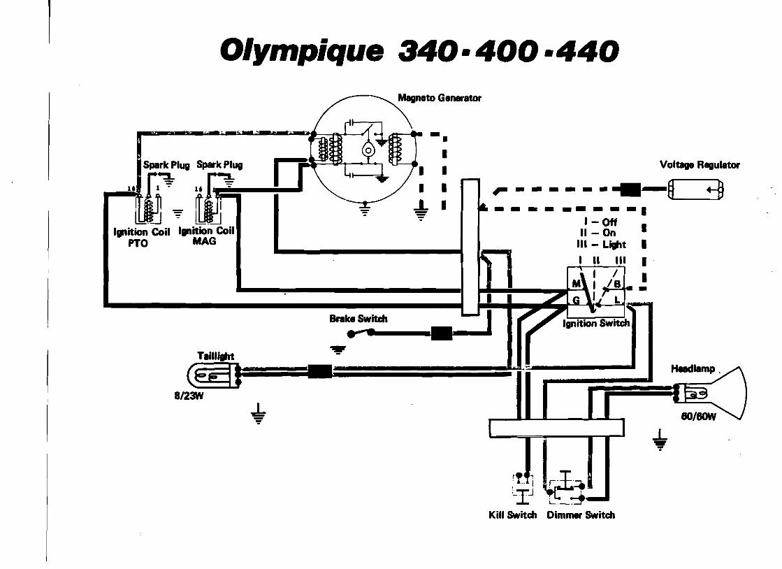
Olvmpique 340·400 ·440
Spark Plug Spark Plug Voltage Regulator ~ n11_ ":" ~ - - - - - •~--6-----.
I - Off II - On
III - Light
I II III
~ II'. L ••• , I 18
- - - I. L
-I I I
!-
.• I
I
I 1
'I ~' +)
lOC1 ":" IlIJI
Ignition Coil Ignition Coil •PTO MAG I I' I
•
Tlill"t I I C$F4]ns.-~
t'
812M
+ ~
":'
...! i:r""~L-IJ ,- .....L._:::T'
Kill Switch Dimmer Switch
.
--
'\ 'j ,.
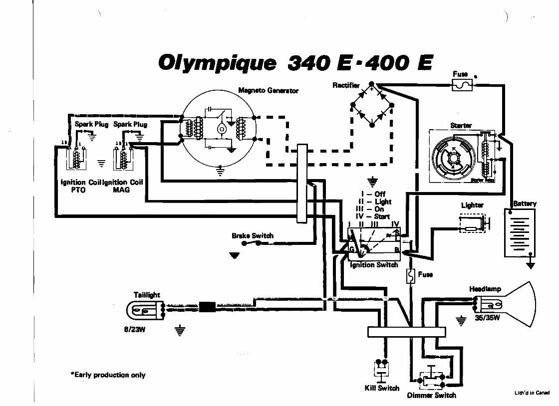
O/ympique 340 E·400 E Fu••
Ignition Coiliinition Coil PTO MAG
Taillight 1_.1
@i¢{}= : --==-,' ~
8/2M 'S' ":'
r-+·-:J..·Early production only g
I . ~ ":'
••1-_. I
• -.-.:: 2_' I -
I -
rt'!LI...J Kill Switch
Dimmer Switch
I I
I-BatteryLight.
Brake Switch .. - • ---------
lith'd in CaI1ld
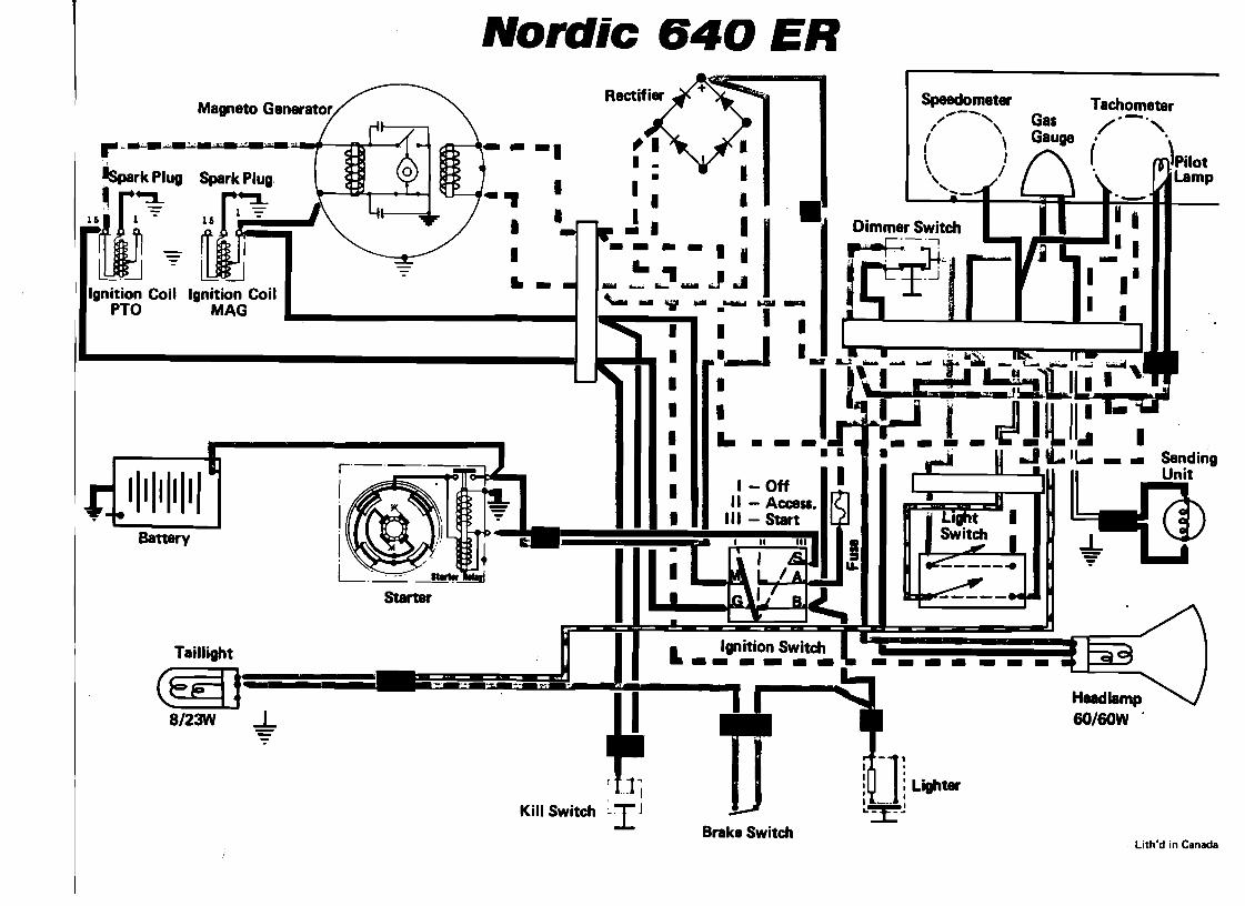
Nordic 640 ER Speedomet. Tachometer ....-
/ '" "\ Gas /--". I \ Gauge
If~ua "[~ ~
Illgnition Coil ~O
1111 111111 Battery
Taillight --=====-iiiii@g]8/23W -!
Sending Unit..
'-( m)Pilot
'Lamp
H8Idiamp SO/SOW'
I I •. , I I.- : -I .1
I I
( I \ /
" ...-
1~ -]1 Ligh-
I I
...
I~'-"Kill Switch
I;-I J "T· Brake Switch
•
I
• I
I I
I
I
• I
; I- .'• I I
- ~ -'_ ..P...'-_IWlI_-..",_-· . I
:--1 I
I
I I
, .. ]-~
r-·.;.·.....-"-'-=- ,._"._.
an
.. I
Ignition Coil M~' I
Lith'd in Canada
------
-- --
---
) 'j
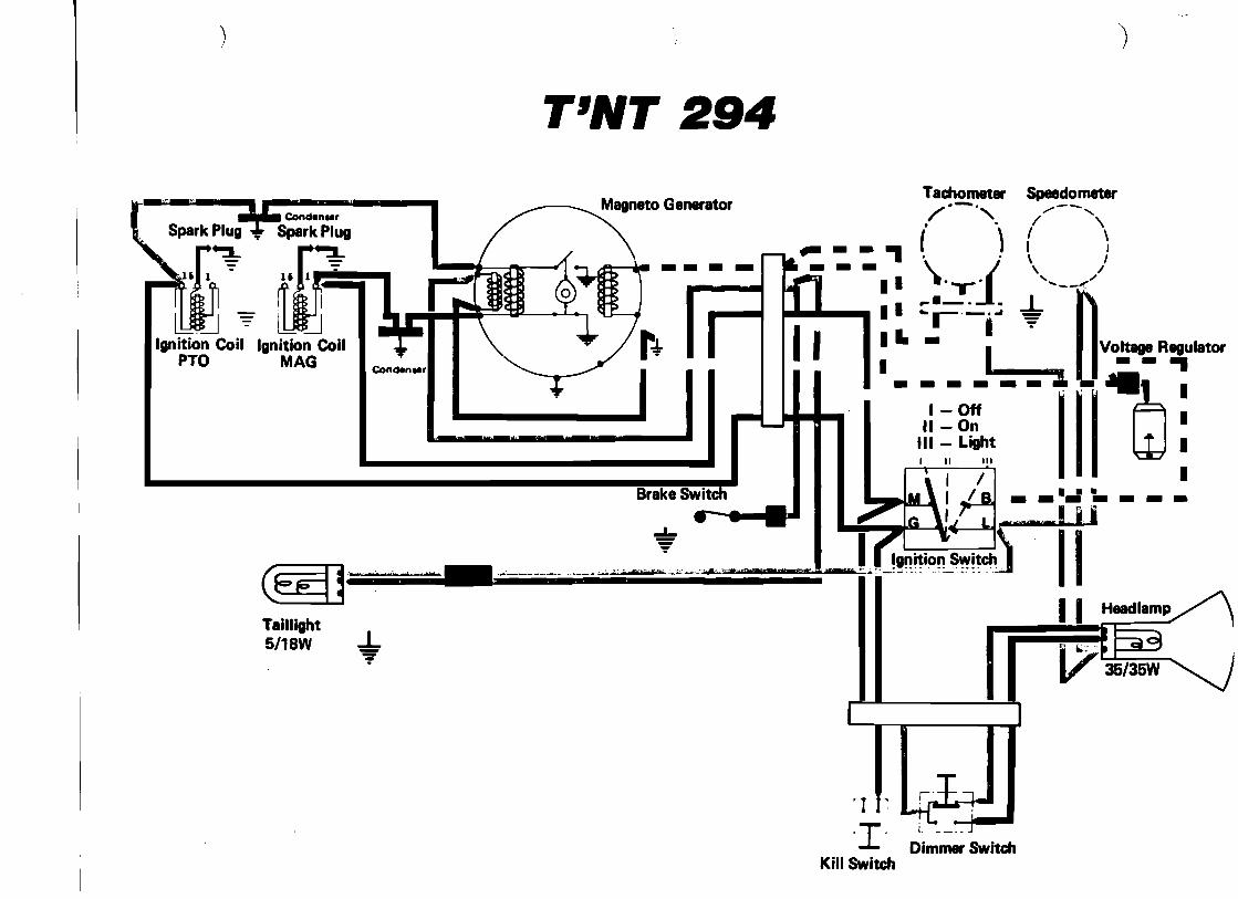
T'NT 294
Magneto Generator
m ~ l1Jj Ignition Coil Ignition Coil
PTO MAG t*Conden..,
I
Brake Switl
-;@::j'_' 't" ', ......... _,....:..----••••--- ..•._ .... ._;.,,,.,,,_>;;......;•.-..:'·.'c_,'='
III
II -_.~ ~
Taillight 5/18W +
'I r-I'
Tachomet. Speedometer/"-', .....--.,. . / \
----,( ) ( )--- \ 1 \I I ....-. ' ..._-.-r ....I
rill ;~ Y:..r +:L I IVoitage Regu~tor I - Off
II - On III - Light
II Headlamp
Dim~Switch
~ --1'1
Kill Switch
• •
V80/6OW
I - Off II On
III Light
-------.
- - -- - - - •
..
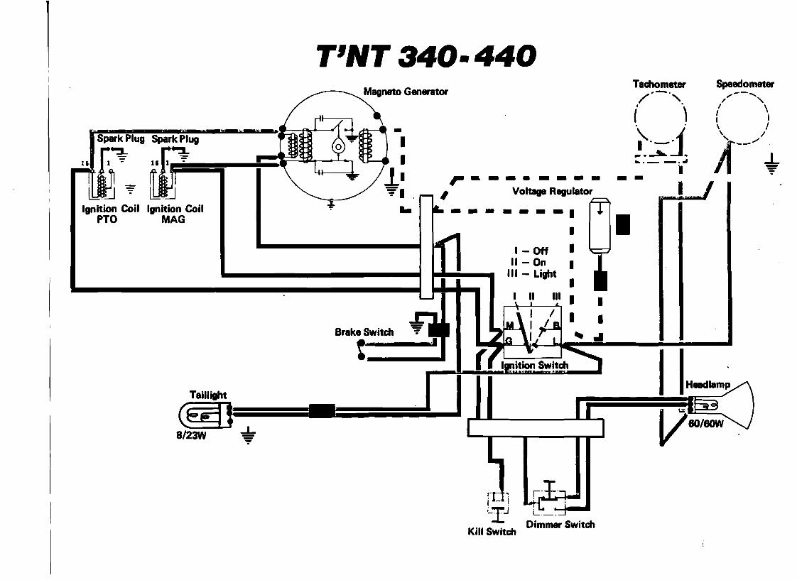
T'NT 340- 440
Spark Plug Spark Plug ~ r~
~f~ 0;0Ignition Coil Ignition Coil
PTO MAG
Taillight
8/23W -+
,. .. _-----Voltage Regulator
I
IIHeod_~
iIJ, L. __t.-IJ
Kill Switch Dimmer Switch
Tachometer Speedometer/--., ,,--, I' "i 0, / \
I I o • \ J
\, I
~.~ . Ia. _ _ o.A
~o_j jf----+ -- •I
') )
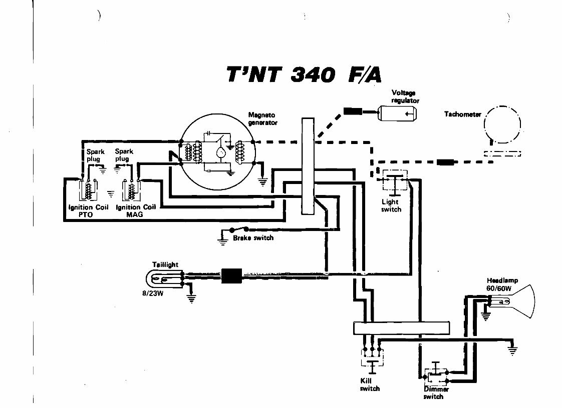
T'NT 340 F/A Volt8ge
--fl ngulotor Tachometer ./.-'"
,-" +j]
60/60W
( ) )._.j----- ... -_._- .I ... , .oJ
1-----... --I'·_·j
1 ..,......•'T'L. ..J
LightIgnition Coil switch
PTO
I· ... _ Brake switch
Taillight I(Ep--J:; ='.t~is=T= Headlamp -8/23W ~
LJ II ~I Kill switch
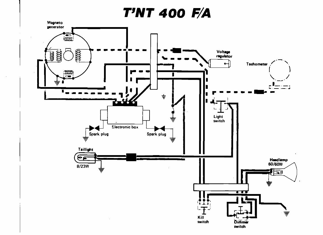
T'NT 400 F/A Magneto
----1_ ..
..",'$' r.!
generator
- - - --1- - - -... ~
Tachometer / . - '" . -- , (.
)I. " i II I" -I I --,.,I I
"_, ~!1 ..l...
~~ ~Iectronic box
1-Spark plug
Taillight
I \. / _1_._I .. ---_.~r-- --- .-I r 1
ItIjll · Light switch
Voltage regulator
....
~
--•I I
I II
I I I
I I I
Ki~1 iJ.••& ! switch L-IJ
•
I I
I I I
---------.-
Taillight(1#59-
I
~LltJ Ignition Coil Ignition Coil. •
MAG
) )
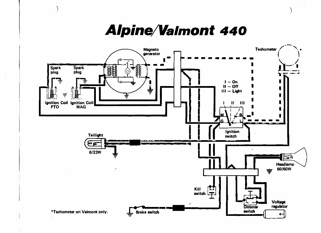
Alpine/Valmonf 440 Tachometer /"-',
( ",* '- II J.C"·
I ".1' 'tr" :=:~ I
I - On I II - Off I IIII - Light I ILIJtJ ~
I PTO
8/23W -:;
L·... *Tachometer.on Valmont onlv" -== Brake switch
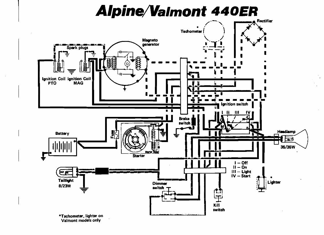
Alpine!Valmonf 440ER .'/'-'", .
Tachometer ( ). .
\. / ....J~. ~. __... • I· - •
1
• 1.1 ~ II I I 1U:' ,di.:se: 1_ _ u _ ,
I
r1..Lr
. - - ~ I I~ __ _1 __
~ 1 I
•• I I i I
Brake ... switch.
r e -.J
+ • i.=:i·::I·=·======·=?====~I - •• 2!:! II •• • • ••
---1 _
I I
--T
T
Battery
1111 111111
Ignition Coil Ignition Coil PTO MAG
Kill switch
·Tachometer, lighter on Valmont models only
--- ----------
') ) :,',
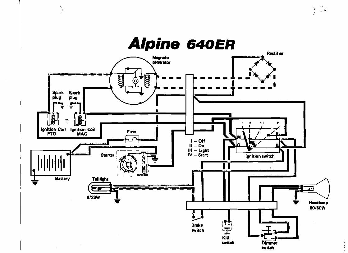
Alpine 640ER Rectifier--- IZ
~_ltf _ '·~",G;_~,y.._·tM...~:JRi\ t .......r. I ~.• ~ "WI • I I "-.i .. _
Spark
I •
lOCJ ~ Ignition Coil
PTa
1111111111 Battery--•
-
!, II
-
1\III
1- Off 11- On
III - Light IV - Start
I '"
~ l.bI[J
Ignition Coil MAG
Heldlamp 6O/60W
Brake I .switch i..IJ
Kill switch bimm.
switch
3-3
.- " - . ~ .
3-03-01
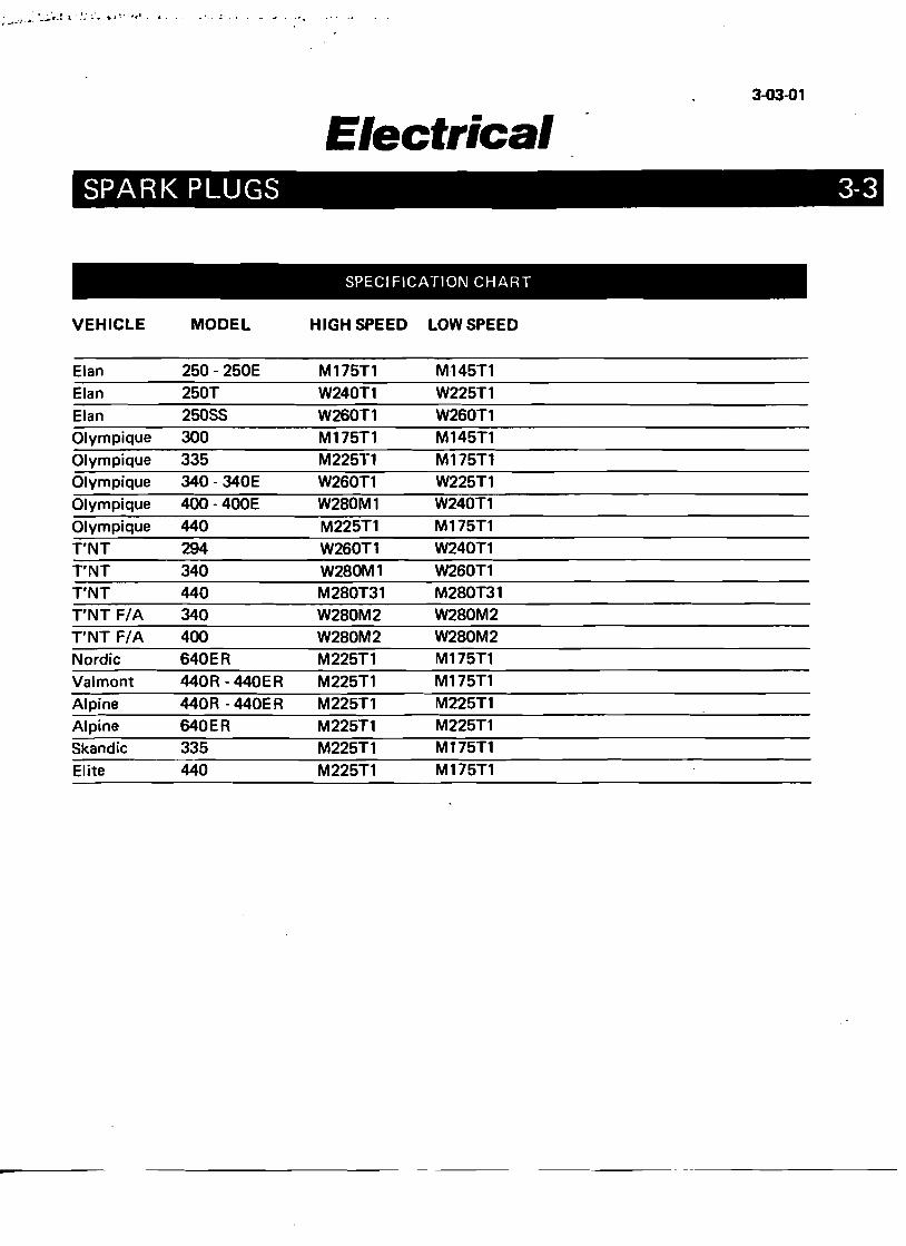
Electrical SPARK PLUGS
SPECIFICATION CHART
VEHICLE MODEL HIGH SPEED LOW SPEED
Elan 250 - 250E M175T1 M145T1 Elan 250T W240T1 W225T1 Elan 25055 W260T1 W260T1 Olympique 300 M175T1 M145T1 Olympique 335 M225T1 M175T1 Olympique 340·340E W260Tl W225T1 Olympique 400 - 400E W280Ml W240T1 Olympique 440 M225T1 M175Tl T'NT 294 W260T1 W240T1 T'NT 340 W280Ml W260Tl T'NT 440 M280T31 M280T31 T'NT F/A 340 W280M2 W280M2 T'NT F/A 400 W280M2 W280M2 Nordic 640ER M225Tl M175T1
Valmont 440R - 440ER M225Tl M175T1
Alpine 440R - 440ER M225Tl M225T1 Alpine 640ER M225T1 M225Tl 5kandic 335 M225T1 M175T1
Elite 440 M225T1 M175T1
3.Q4.Q1
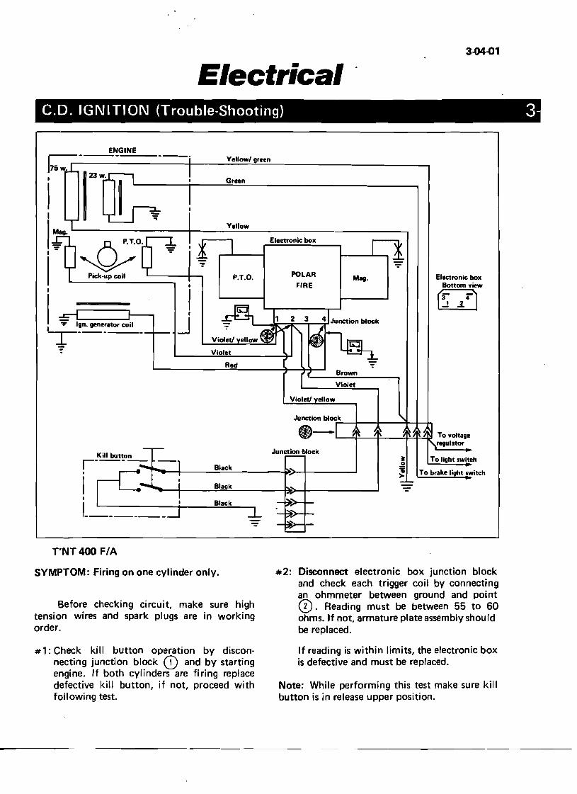
Electrical C.D. IGNITION (Trouble-Shooting) 3
#2: Disconnect electronic box junction block and check each trigger coil by connecting an ohmmeter between ground and pointCD. Reading must be between 55 to 60 ohms. If not, armature plate assembly shou Id be replaced.
Green
Electronic box Bottom view
r:- r)..! .:L
Mag.POLAR FIRE
Electronic box
P.T.O.
Yellow
Yellowl green
I
II
J
__,;;;;ENGINE
~o Pick.up coil '-----+--,
Red Brown
Violet
Violet! ellow
To light switch
To brake light switch
it o 'i >
1!!iIJA_.......--.,..=---.,..=----=+'~ To voltage'IIIfI!J1 regulator
Junction block
Black
Black
Kill button,----, r-1---t-__~BI;.::.ac;;;.k=--- -i~-+- """"
I I
'-------T'NT 400 F/A
SYMPTOM: Firing on one cylinder only.
Before checking circuit, make sure high tension wires and spark plugs are in working order.
#1: Check kill button operation by discon If reading is within limits, the electronic box necting junction block CD and by starting is defective and must be replaced. engine. If both cylinders are firing replace defective kill button, if not, proceed with Note: While performing this test make sure kill following test. button is in release upper position.
3-04-02
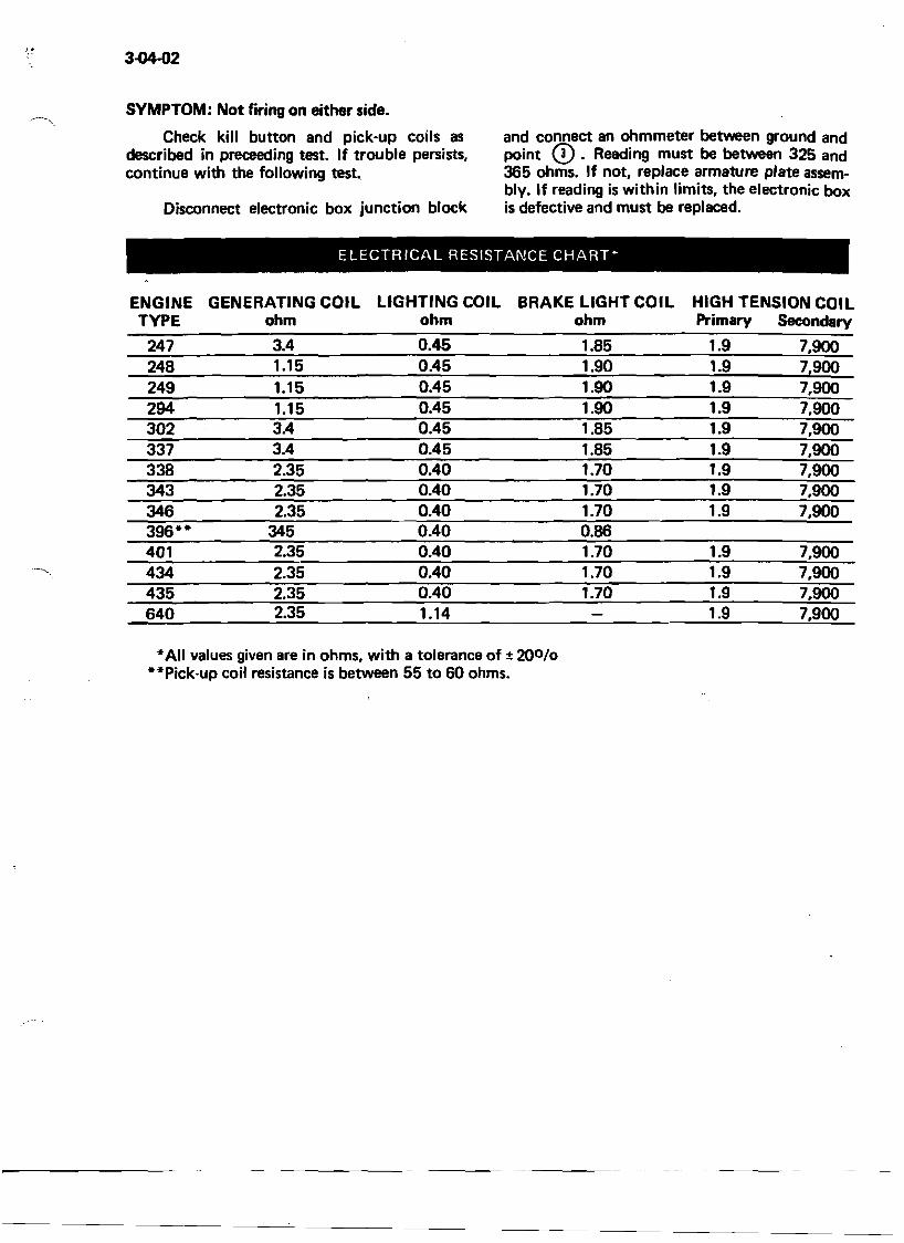
SYMPTOM: Not firing on either side.
Check kill button and pick-up coils as and connect an ohmmeter between ground and described in preceeding test. If trouble persists, point CD. Reading must be between 325 and continue with the following test. 365 ohms. If not, replace armature plate assem
bly. If reading is within limits, the electronic box Disconnect electronic box junction block is defective and must be replaced.
ELECTRICAL RESISTANCE CHART""
ENGINE GENERATING COIL LIGHTING COIL BRAKE LIGHT COIL HIGH TENSION COIL TYPE ohm ohm ohm Primary Secondary
247 3.4 0.45 1.85 1.9 7,900 248 1.15 0.45 1.90 1.9 7,900 249 1.15 0.45 1.90 1.9 7,900 294 1.15 0.45 1.90 1.9 7,900 302 3.4 0.45 1.85 1.9 7,900 337 3.4 0.45 1.85 1.9 7,900 338 2.35 0.40 1.70 1.9 7,900 343 2.35 0.40 1.70 1.9 7,900 346 2.35 0.40 1.70 1.9 7,900 396-- 345 0.40 0.86 401 2.35 0.40 1.70 1.9 7,900
----~.. 434 2.35 0.40 1.70 1.9 7,900 435 2.35 0.40 1.70 1.9 7,900 640 2.35 1.14 1.9 7,900
•All values given are in ohms, with a tolerance of ± 200 /0
"Pick-up coil resistance is between 55 to 60 ohms.
BODY AND FRAME
4
4-01-01
Body & Frame GENERAL
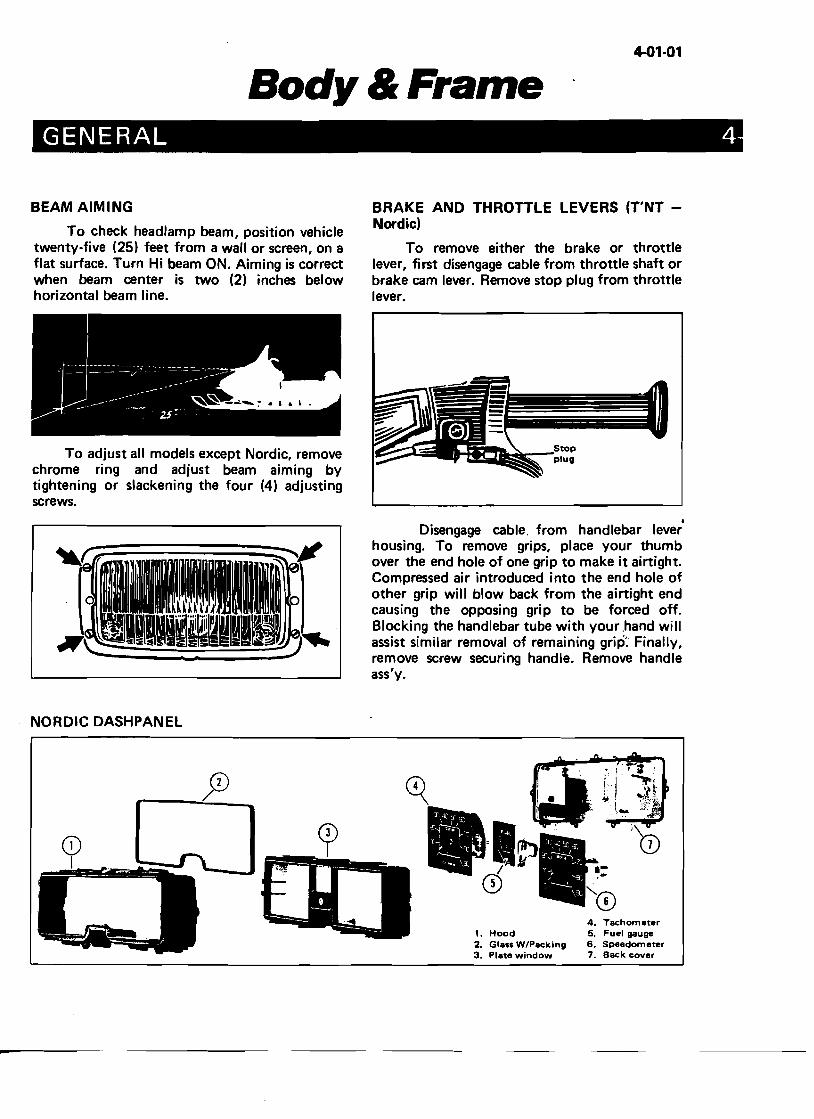
BEAM AIMING
To check headlamp beam, position vehicle twenty-five (25) feet from a wall or screen, on a flat surface. Turn Hi beam ON. Aiming is correct when beam center is two (2) inches below horizontal beam line.
To adjust all models except Nordic, remove chrome ring and adjust beam aiming by tightening or slackening the four (4) adjusting screws.
NORDIC DASHPANEL
BRAKE AND THROTTLE LEVERS (T'NT Nordic)
To remove either the brake or throttle lever, first disengage cable from throttle shaft or brake cam lever. Remove stop plug from throttle lever.
Disengage cable. from handlebar lever' housing. To remove grips, place your thumb over the end hole of one grip to make it airtight. Compressed air introduced into the end hole of other grip will blow back from the airtight end causing the opposing grip to be forced off. Blocking the handlebar tube with your ,hand will assist similar removal of remaining grip: Finally, remove screw securing handle. Remove handle ass'y.
CD/
CD I
t. Hood 2. Glass W/Packing 3. Plate window
4. Tachometer 5. Fuel gauge 6. Speedometer 7. Back cover
4-01-G2
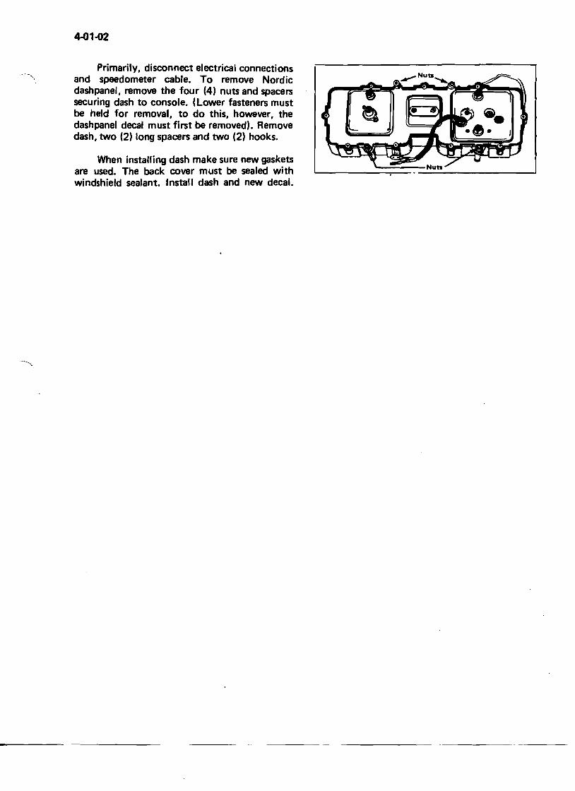
Primarily, disconnect electrical connections --, and speedometer cable. To remove Nordic
dashpanel, remove the four (4) nuts and spacers securing dash to console. (Lower fasteners must be held for removal, to do this, however, the dashpanel decal must first be removed). Remove dash, two (2) long spacers and two (2) hooks.
When installing dash make sure new gaskets are used. The back cover must be sealed with windshield sealant. Install dash and new decal.
TOOLS
-
5-01-1
Special Tools
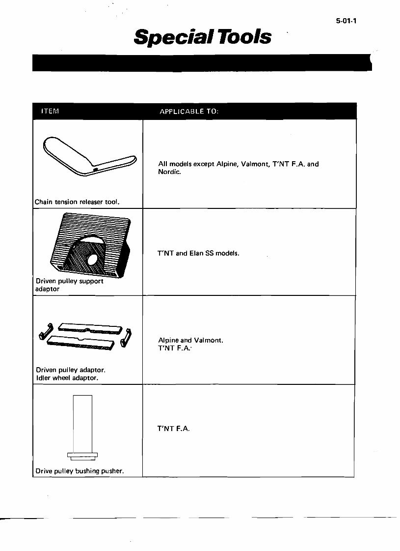
ITEM APPLICABLE TO:
Chain tension releaser tool.
Driven pulley support adaptor
All models except Alpine, Valmont, TNT F.A. and Nordic.
TNT and Elan 55 models.
Driven pulley adaptor. Idler wheel adaptor.
Alpine and Val mont. TNT F.A:
Drive pulley bushing pusher.
TNT F.A.
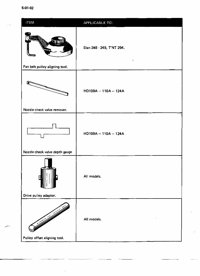
5-01-02
ITEM APPLICABLE TO:
Elan 248 - 249, T'NT 294.
Fan belt pulley aligning tool.
HD109A - 110A - 124A
Nozzle check valve remover.
~ nL.....__
u
Nozzle check valve depth gauge
HD109A-ll0A-124A
All models.
Drive pulley adaptor.
All models.
..,---..
Pulley offset aligning tool.
1973 SKI-DOD WARRANTY
Bombardier Limited (Bombardier) as manufacturer, warrants every 1973 Ski-Doo snowmobile, Ski-Boose or Carry-Boose tow sled, SOLD AS A NEW VEHICLE, BY AN AUTHORIZED SKI-DOa DEALER, to be free from defects in material, and workmanship under normal use and service, for a period of ninety (90) days subject to the following coverage period:
1. Beginning no sooner than from the date of delivery to the first retail buyer, for a period of ninety (90) consecutive days.
2. Since snow is required for snowmobiling; all deliveries prior to December 15th, 1972, shall be covered under this warranty from December 15th, 1972 to March 15th, 1973.
3. All units delivered on or after January 2nd, 1973, but prior to March 31st, 1973, shall have a warranty carry-over into the next season, starting on December 15th, 1973, for the unused portion of the ninety (90) day warranty.
CONDITIONS
1. That maintenance be performed, at the owner's expense, as set down in the applicable owner's manual. Any failure which occurs as a result of inadequate maintenancet or improper use shall not be assumed by this warranty.
2. Any damages to any part of the above-mentioned vehicles and their components caused through improper use or maintenance or by any part installed which is not a genuine Ski-Doo replacement part, or not installed by an authorized Ski-Doo dealer, voids any future warranty coverage to the affected parts.
3. This warranty does not apply to any defect which results from:
i) misuse or accident; ii) Installation of repair parts other than genuine Bombardier replacement parts or;
iii) Repairs by any person other than an authorized Ski-Doo snowmobile dealer; iv) Lack of preventative maintenance; v) Alterations or modifications other than those approved in writing by Bombardier.
4. Proof of ownership and warranty registration must be submitted to the service dealer by means of the Ski-Doo Service Card.
t Guidelines for proper use and maintenance are detailed in each owner's manual.
EXCLUSIONS
• Maintenance Items and Services are considered non-warrantable and necessary to proper functioning of the vehicle, and without limiting the foregoing the following parts and services are excluded:
• Variable speed drive belt, windshield, filters, ignition breaker points and condensers, spark plugs, light bulbs and protective lenses, brake linings, ski runner shoes, slider shoes on variable speed pulleys, all fasteners, labels, soft trim and appearance items, lubricants and paints, and all tune-ups or adjustments required.
WARRANTY ON GENUINEACCESSORIES AND REPLACEMENTPARTS
BOMBARDIER LIMITED ("Bombardier") warrants to the original retail purchaser that any of the following genuine Bombardier accessories: tachometer, speedometer, front bumper, rear bumper and side handles and/or genuine Bombardier replacement parts which are normally covered under the new product warranty, sold as new by an authorized Ski-Doo dealer, will be free from defects in material and workmanship under normal use and service for a period of 90 consecutive days from the date of original retail purchase or from the date of the first snowfall, if purchase took place before, in which case the date of the first snowfall shall be deemed to be no later than the 15th of December 1972.
ANY OF THE SAID REPLACEMENT PARTS REPLACED UNDER THE ORIGINAL SKI-DOO WARRANTY SHALL NOT BE COVERED UNDER THE PRESENT WARRANTY.
Bombardier's obligation under this warranty is strictly limited to the repair or replacement at its option, of any part or parts thereof which shall, within the specified warranty period, be returned to an authorized Ski-Doo dealer at such dealer's place of business with the original Bill of Sale and which examination shall disclose to the satisfaction of Bombardier to have been thus defective, BEING CLEARLY ESTABLISHED THAT THE PRESENT WARRANTY APPLIES ONLY TO SAID ACCESSORIES AND/OR REPLACEMENT PARTS WHICH HAVE BEEN SOLD AND INSTALLED, WHEN THE CASE MAY BE, BY AN AUTHORIZED SKI·DOO DEALER. The repair or replacement of defective parts under this warranty will be made by such dealer wit~out charge for parts for th, above-mentioned accessories and replacement parts, if made at such dealer's place of business.
THIS WARRANTY DOES NOT APPLY to any accessories and/or replacement part which:
a) have been subjected to any misuse, alteration, modification, or accident; b) have been repaired with parts other than genuine Bombardier replacement parts, or; c) have been repaired by any person other than authorized Ski-Doo dealer.
THIS WARRANTY IS EXPRESSLY IN LIEU OF ALL OTHER EXPRESSED OR IMPLIED WARRANTIES OF BOMBARDIER, ITS DISTRIBUTORS AND THE SELLING DEALER, INCLUDING ANY IMPLIED WARRANTY OR MERCHANTABILITY OR FITNESS FOR ANY PARTICULAR PURPOSE, NEITHER BOMBARDIER, ITS DISTRrBUTORS NOR THE SELLING DEALER SHALL BE RESPONSIBLE, UNDER ANY CIRCUMSTANCES, FOR ANY LOSS OR DAMAGE INCURRED AS A RESULT OF HIDDEN DEFECTS, ACCIDENTS, MISUSES OR OTHER FAULTS.
NEITHER THE DISTRIBUTOR, THE SELLING DEALER NOR ANY OTHER PERSON HAS BEEN AUTHORIZED TO MAKE ANY AFFIRMATION, REPRESENTATION, 'OR WARRANTY OTHER THAN THOSE CONTAINED IN THIS WARRANTY, AND, IF MADE, SUCH AFFIRMATION, REPRESENTATION OR WARRANTY SHALL NOT BE ENFORCEABLE AGAINST BOMBARDIER OR ANY OTHER PERSON.
BOMBARDIER LIMITED, February 2nd, 1972.
---~---
1
• Any part damaged through lack of lubrication unless it is proven to be attributable to a manufacturing defect.
• Blizzard models or any of the vehicles referred to in this text which may have been used for racing or professional competition.
• Any damages resulting from an accident unless such damages are proven to result from a manufacturing defect.
• Any losses incurred to the vehicle owner other than the parts and labour required to repair the warrantable defect.
This warranty is expressly in lieu of all other expressed or implied warranties of Bombardier, its distributors and the selling dealer, including any implied warranty of merchantability or fitness for any particular purpose. Neither Bombardier, its distributors nor the selling dealer shall be responsible, under any circumstances, for any loss or damage as a result of hidden defects, accidents, misuses or other faults.
Neither the distributor~ the selling dealer nor any other person has been authorized to make any affirmation, representation or warranty other than those contained in this warranty and if made, such affirmation, representation or warranty shall not be enforceable against Bombardier or any other person.
BOMBARDIER LIMITED February 2nd, 1972.