Embed Size (px)
Citation preview

The following are trademarks of Bombardier Inc.
BOMBARDIER® SKANDIC* TUNDRA*FORMULA* SKI-DOO® CK3*
Litho’d in Canada®*Trademarks of Bombardier Inc.All rights reserved © Bombardier Inc. 1998 (MMO-9903 GM)
SAFETY WARNING
Disregarding any of the safety precautions and instructionscontained in this Operator’s Guide, Safety Handbook or on-product labels could cause injury, including the possibility ofdeath.
This Operator’s Guide handbook should remain with the snow-mobile at all time.
AFTER SALES SERVICEBOMBARDIER INC.VALCOURT, QUEBECCANADA J0E 2L0
cover_a.fm5 Page 2 Monday, June 15, 1998 10:35 AM
1
1999 SKI-DOO OPERATOR’S GUIDE
This guide is applicable to CK3 series:
Grand Touring 700
Grand Touring SE
Formula III 600
Formula III 700
Formula III 800
Mach 1
Mach 1 R
Mach Z
Mach Z M.H. R
Mach Z R
Mach Z LT
Mach Z LT R
mmo9903a.fm5 Page 1 Wednesday, June 17, 1998 3:47 PM
2
FOREWORD
Congratulations on your purchase of a new SKI-DOO snowmobile.Whatever model you have chosen, it is backed by the Bombardierwarranty and a network of authorized Ski-Doo snowmobile dealersready to provide the parts, service or accessories you may require.
Your dealer is committed to your satisfaction. He has taken trainingto perform the initial set-up and inspection of your snowmobile aswell as completed the final adjustment required to suit your specificweight and riding environment before you took possession. At deliv-ery, your dealer would have explained the snowmobile controls andprovided you with a brief explanation of the various suspension ad-justments. We trust you have taken full advantage of this! If youneed more complete servicing information, please ask your dealerabout the proper model-year Ski-Doo Shop Manual.
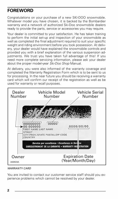
At delivery, you were also informed of the warranty coverage andcompleted the Warranty Registration Form which is to be sent to usfor processing. In the near future you should be receiving a warrantycard which will confirm our receipt of the registration as well as beused for warranty or recall purposes.
WARRANTY CARD
You are invited to contact our customer service staff should you ex-perience problems which cannot be resolved by your dealer.
Vehicle ModelNumber
A00K03A
Expiration Date(Year/Month/Day)
Owner
DealerNumber
Vehicle SerialNumber
mmo9903a.bk : mmo9903a.fm5 Page 2 Monday, June 15, 1998 8:05 AM
3
NOTICE
The Operator’s Guide and the Snowmobiler’s Safety Handbook havebeen prepared to acquaint the owner/operator and passenger of anew snowmobile with the various snowmobile controls, mainte-nance and safe operating instructions. Each is indispensable for theproper use of the product.
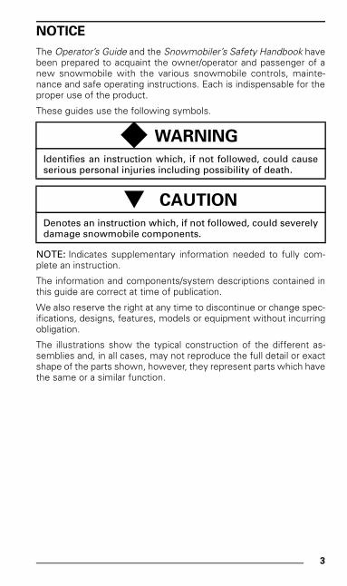
These guides use the following symbols.
NOTE: Indicates supplementary information needed to fully com-plete an instruction.
The information and components/system descriptions contained inthis guide are correct at time of publication.
We also reserve the right at any time to discontinue or change spec-ifications, designs, features, models or equipment without incurringobligation.
The illustrations show the typical construction of the different as-semblies and, in all cases, may not reproduce the full detail or exactshape of the parts shown, however, they represent parts which havethe same or a similar function.
◆ WARNING
Identifies an instruction which, if not followed, could causeserious personal injuries including possibility of death.
- CAUTION
Denotes an instruction which, if not followed, could severelydamage snowmobile components.
mmo9903a.bk : mmo9903a.fm5 Page 3 Monday, June 15, 1998 8:05 AM
4
TABLE OF CONTENTS
;SAFETY MEASURES............................................................ 7
BOMBARDIER LIMITED WARRANTY
1999 SKI-DOO® SNOWMOBILE.............................................. 8
BOMBARDIER INTERNATIONAL LIMITED WARRANTY
1999 SKI-DOO® SNOWMOBILE.............................................. 10
OFTEN ASKED QUESTIONS................................................... 12
LIST OF CUSTOMER RELATIONS OFFICES .......................... 14
AUTHORIZED SKI-DOO DEALERS ......................................... 14
HOW TO IDENTIFY YOUR SNOWMOBILE ............................ 15
Vehicle Serial Number Location ................................................ 15Engine Serial Number Location ................................................. 16
ON-VEHICLE IMPORTANT INSTRUCTIONS.......................... 17
CONTROLS/INSTRUMENTS .................................................. 22
1) Throttle Lever ...................................................................... 262) Brake Lever ......................................................................... 263) Parking Brake Button........................................................... 264) Injection Oil Level/Parking Brake Pilot Lamp (Red).............. 275) Reverse Button ................................................................... 276) Ignition Switch..................................................................... 307) Tether Cut-Out Switch ........................................................ 318) DESS Pilot Lamp ................................................................. 339) Emergency Cut-Out Switch................................................. 34
10) Headlamp Dimmer Switch .................................................. 3511) High Beam Pilot Lamp (Blue) .............................................. 3612) Rewind Starter Handle ........................................................ 3613) Choke Lever ........................................................................ 3714) Air Suspension Switch ........................................................ 3815) Air Suspension Pilot Lamp .................................................. 3916) Air Suspension Gauge ......................................................... 3917) Speedometer....................................................................... 3918) Odometer ............................................................................ 4019) Trip Meter............................................................................ 4020) Trip Meter Reset Button ..................................................... 4121) Tachometer ......................................................................... 4222) Temperature Gauge ............................................................ 4323) Engine Overheat Warning Lamp (Red) ................................ 44
mmo9903a.bk : mmo9903a.toc Page 4 Monday, June 15, 1998 8:05 AM
5
24) Electric Fuel Level Gauge .................................................... 4425) Fuel Tank Cap ...................................................................... 4526) Heated Grip Switch.............................................................. 4627) Heated Grip Pilot Lamp (yellow) .......................................... 4728) Heated Throttle Lever Switch .............................................. 4729) Heated Throttle Lever Pilot Lamp (yellow)........................... 4830) Electric Visor Jack Connector .............................................. 4931) Hood Latches....................................................................... 4932) Adjustable Mirrors................................................................ 4933) Adjustable Toeholds............................................................. 50Adjustable Backrest ................................................................... 51Adjustable Rear Grab Handles ................................................... 52Hood Grills ................................................................................. 53Fuel Shut-Off Valve .................................................................... 54Storage Compartment ............................................................... 54Tool Box ..................................................................................... 55Spark Plug Holder ...................................................................... 56Spare Drive Belt Holder ............................................................. 57Fuses ......................................................................................... 57Front Grab Handles/Front Bumper............................................. 59Hitch........................................................................................... 59
FUEL AND OIL .......................................................................... 60
Recommended Fuel................................................................... 60Recommended Oil ..................................................................... 60
COLD WEATHER CARBURETION MODIFICATIONS ............. 61
BREAK-IN PERIOD.................................................................... 62
Engine ........................................................................................ 62Belt............................................................................................. 6210-Hour Inspection..................................................................... 62
PRE-START CHECK .................................................................. 63
Check Points .............................................................................. 63
STARTING PROCEDURE.......................................................... 65
Warm Engine Starting................................................................ 66Manual Starting.......................................................................... 66Electric Starting (some models only) ......................................... 66Emergency Starting ................................................................... 66
SUSPENSION ADJUSTMENTS............................................... 69
General....................................................................................... 69Guidelines to Adjust Suspension ............................................... 70
mmo9903a.bk : mmo9903a.toc Page 5 Monday, June 15, 1998 8:05 AM
6
TROUBLESHOOTING CHART ................................................. 86
In Deep Snow............................................................................ 86
LUBRICATION AND MAINTENANCE CHART........................ 87
FLUID LEVELS.......................................................................... 89
Brake System ............................................................................ 89Chaincase Oil Level ................................................................... 89Oil Injection System .................................................................. 91Cooling System ......................................................................... 92Battery Electrolyte..................................................................... 92
MAINTENANCE ....................................................................... 93
Guard Removal and Installation................................................. 93Drive Belt Removal/Installation ................................................. 95Drive Chain Tension .................................................................. 98TRA Drive Pulley Adjustment .................................................... 99Drive Belt Condition .................................................................. 101Brake Condition ......................................................................... 101Brake Adjustment...................................................................... 102Rear Suspension Condition ....................................................... 102Suspension Stopper Strap Condition......................................... 102Track Condition.......................................................................... 102Track Tension and Alignment .................................................... 103Steering and Front Suspension Mechanism ............................. 107Wear and Condition of Skis and Runners.................................. 107Exhaust System ........................................................................ 108Air Filter Cleaning ...................................................................... 108High Altitude Kit ........................................................................ 111Headlight Beam Aiming............................................................. 111Bulb Replacement ..................................................................... 112Towing....................................................................................... 115
STORAGE ................................................................................. 115
TROUBLESHOOTING .............................................................. 116
SPECIFICATIONS ..................................................................... 120
OTHER PUBLICATIONS AVAILABLE...................................... 123
CHANGE OF ADDRESS OR OWNERSHIP.............................. 124
mmo9903a.bk : mmo9903a.toc Page 6 Monday, June 15, 1998 8:05 AM
7
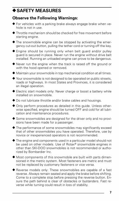
;SAFETY MEASURES
Observe the Following Warnings:
; For vehicles with a parking brake always engage brake when ve-hicle is not in use.
; Throttle mechanism should be checked for free movement beforestarting engine.
; The snowmobile engine can be stopped by activating the emer-gency cut-out button, pulling the tether cord or turning off the key.
; Engine should be running only when belt guard and/or pulleyguard is secured in place. Never run the engine without drive beltinstalled. Running an unloaded engine can prove to be dangerous.
; Never run the engine when the track is raised off the ground orwith the hood opened or removed.
; Maintain your snowmobile in top mechanical condition at all times.
; Your snowmobile is not designed to be operated on public streets,roads or highways. In most States and Provinces, it is consideredan illegal operation.
; Electric start models only: Never charge or boost a battery whileinstalled on snowmobile.
; Do not lubricate throttle and/or brake cables and housings.
; Only perform procedures as detailed in this guide. Unless other-wise specified, engine should be turned OFF and cold for all lubri-cation and maintenance procedures.
; Some snowmobiles are designed for the driver only and no provi-sions have been made for a passenger.
; The performance of some snowmobiles may significantly exceedthat of other snowmobiles you have operated. Therefore, use bynovice or inexperienced operators is not recommended.
; The engine and components used in a particular model should notbe used on other models. Use of Rotax® snowmobile engines inother than SKI-DOO snowmobiles is not recommended or autho-rized by Bombardier Inc.
; Most components of this snowmobile are built with parts dimen-sioned in the metric system. Most fasteners are metric and mustnot be replaced by customary fasteners or vice versa.
; Reverse models only: These snowmobiles are capable of a fastreverse. Always remain seated and apply the brake before shifting.Come to a complete stop before pressing the reverse button. En-sure the path behind is clear of obstacles or bystanders. Fast re-verse while turning could result in loss of stability.
mmo9903a.bk : mmo9903b.fm5 Page 7 Monday, June 15, 1998 8:05 AM
8
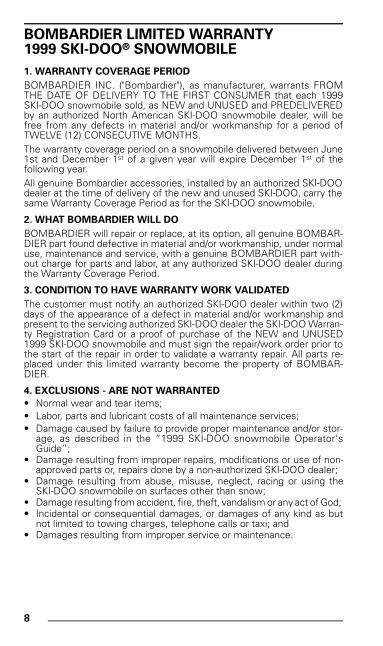
BOMBARDIER LIMITED WARRANTY1999 SKI-DOO® SNOWMOBILE
1. WARRANTY COVERAGE PERIOD
BOMBARDIER INC. ("Bombardier"), as manufacturer, warrants FROMTHE DATE OF DELIVERY TO THE FIRST CONSUMER that each 1999SKI-DOO snowmobile sold, as NEW and UNUSED and PREDELIVEREDby an authorized North American SKI-DOO snowmobile dealer, will befree from any defects in material and/or workmanship for a period ofTWELVE (12) CONSECUTIVE MONTHS.The warranty coverage period on a snowmobile delivered between June1st and December 1st of a given year will expire December 1st of thefollowing year.All genuine Bombardier accessories, installed by an authorized SKI-DOOdealer at the time of delivery of the new and unused SKI-DOO, carry thesame Warranty Coverage Period as for the SKI-DOO snowmobile.
2. WHAT BOMBARDIER WILL DO
BOMBARDIER will repair or replace, at its option, all genuine BOMBAR-DIER part found defective in material and/or workmanship, under normaluse, maintenance and service, with a genuine BOMBARDIER part with-out charge for parts and labor, at any authorized SKI-DOO dealer duringthe Warranty Coverage Period.
3. CONDITION TO HAVE WARRANTY WORK VALIDATED
The customer must notify an authorized SKI-DOO dealer within two (2)days of the appearance of a defect in material and/or workmanship andpresent to the servicing authorized SKI-DOO dealer the SKI-DOO Warran-ty Registration Card or a proof of purchase of the NEW and UNUSED1999 SKI-DOO snowmobile and must sign the repair/work order prior tothe start of the repair in order to validate a warranty repair. All parts re-placed under this limited warranty become the property of BOMBAR-DIER.
4. EXCLUSIONS - ARE NOT WARRANTED
• Normal wear and tear items;• Labor, parts and lubricant costs of all maintenance services;• Damage caused by failure to provide proper maintenance and/or stor-
age, as described in the “1999 SKI-DOO snowmobile Operator'sGuide”;
• Damage resulting from improper repairs, modifications or use of non-approved parts or, repairs done by a non-authorized SKI-DOO dealer;
• Damage resulting from abuse, misuse, neglect, racing or using theSKI-DOO snowmobile on surfaces other than snow;
• Damage resulting from accident, fire, theft, vandalism or any act of God; • Incidental or consequential damages, or damages of any kind as but
not limited to towing charges, telephone calls or taxi; and• Damages resulting from improper service or maintenance.
mmo9903a.bk : mmo9903b.fm5 Page 8 Monday, June 15, 1998 8:05 AM
9
5. LIMITATIONS OF LIABILITY
This warranty gives you specific rights, and you may also have other legalrights which may vary from state to state, or province to province.WHERE APPLICABLE, THIS WARRANTY IS EXPRESSLY GIVEN ANDACCEPTED IN LIEU OF ANY AND ALL OTHER WARRANTIES, EX-PRESSED OR IMPLIED, INCLUDING WITHOUT LIMITATION ANYWARRANTY OF MERCHANTABILITY OR FITNESS FOR ANY PARTIC-ULAR PURPOSE.
Neither the distributor, any authorized SKI-DOO dealer nor any other per-son has been authorized to make any affirmation, representation or war-ranty other than those contained in this warranty, and if made, suchaffirmation, representation or warranty shall not be enforceable againstBOMBARDIER or any other person.In no event shall BOMBARDIER be liable for special, consequential orincidental damages, including but not limited to loss of use and transpor-tation costs. Some states or provinces do not allow the exclusion or lim-itation of incidental or consequential damages, or limitations on how longan implied warranty lasts, so the above limitation or exclusion may notapply.BOMBARDIER reserves the right to modify this warranty at any time,being understood that such modification will not alter the warranty con-ditions applicable to the SKI-DOO snowmobile sold while this warranty isin effect.
6. CONSUMER ASSISTANCE
a) In the event of a controversy or a dispute arising in connection with thisBOMBARDIER LIMITED WARRANTY, BOMBARDIER suggests thatyou try to resolve the issue at the dealership level. We recommenddiscussing the issue with the authorized dealer's service manager orowner.
b) If further assistance is required, the DISTRIBUTOR's Service Depart-ment should be contacted in order to resolve the matter.
c) If the issue has still not been resolved, please submit in writing yourcomplaint to:
BOMBARDIER INC.RECREATIONAL PRODUCTSSNOWMOBILES
January 1998
® Registered trademark of Bombardier Inc. and/or affiliates.
In Canada:
BOMBARDIER INC.RECREATIONAL PRODUCTSSNOWMOBILESCUSTOMER ASSISTANCE CENTERVALCOURT QC J0E 2L0
Tel: (450) 532-5000
In USA:
BOMBARDIER MOTORCORPORATION OF AMERICARECREATIONAL PRODUCTSSNOWMOBILESCUSTOMER ASSISTANCE CENTERP.O. BOX 80357575 BOMBARDIER COURTWAUSAU WI 54402-8035
Tel: (715) 848-4957
mmo9903a.bk : mmo9903b.fm5 Page 9 Monday, June 15, 1998 8:05 AM
10
BOMBARDIER INTERNATIONALLIMITED WARRANTY1999 SKI-DOO® SNOWMOBILE
1. WARRANTY COVERAGE PERIOD
BOMBARDIER INC. ("Bombardier"), as manufacturer, warrants FROMTHE DATE OF DELIVERY TO THE FIRST CONSUMER that each 1999SKI-DOO snowmobile sold anywhere in the world except the UnitedStates and Canada, as NEW and UNUSED and PREDELIVERED by anauthorized SKI-DOO snowmobile dealer, duly appointed by an authorizedSKI-DOO International Distributor, will be free from any defects in mate-rial and/or workmanship for a PERIOD of TWELVE (12) CONSECUTIVEMONTHS.
All genuine Bombardier accessories, installed by an authorized SKI-DOOdealer at the time of delivery of the new and unused SKI-DOO snowmo-bile, carry the same Warranty Coverage Period as for the SKI-DOO snow-mobile.
2. WHAT BOMBARDIER WILL DO
BOMBARDIER through the local SKI-DOO International Distributor will,during the Warranty Coverage Period, repair or replace, at its option, allgenuine BOMBARDIER part found defective in material and/or workman-ship, under normal use, maintenance and service, with a genuine BOM-BARDIER part without charge for parts and labor, at any local authorizedSKI-DOO dealer.
3. CONDITION TO HAVE WARRANTY WORK VALIDATED
The customer must notify a local authorized SKI-DOO dealer within two(2) days of the appearance of a defect in material and/or workmanshipand present to the servicing authorized SKI-DOO dealer the SKI-DOOWarranty Registration Card or a proof of purchase of the NEW and UN-USED 1999 SKI-DOO snowmobile and must sign the repair/work orderprior to the start of the repair in order to validate a warranty repair. Allparts replaced under this limited warranty become the property of BOM-BARDIER.
4. EXCLUSIONS - ARE NOT WARRANTED
• Normal wear and tear items;• Labor, parts and lubricant costs of all maintenance services;• Damage caused by failure to provide proper maintenance and/or stor-
age, as described in the “1999 SKI-DOO snowmobile Operator'sGuide”;
• Damage resulting from improper repairs, modifications or use of non-approved parts or, repairs done by a non-authorized SKI-DOO dealer;
• Damage resulting from abuse, misuse, neglect, racing or using theSKI-DOO snowmobile on surfaces other than snow;
• Damage resulting from accident, fire, theft, vandalism or any act of God;• Incidental or consequential damages, or damages of any kind as but
not limited to towing charges, telephone calls or taxi; and • Damages resulting from improper service or maintenance.
mmo9903a.bk : mmo9903b.fm5 Page 10 Monday, June 15, 1998 8:05 AM
11
5. LIMITATIONS OF LIABILITY
This warranty gives you specific rights, and you may also have other legalrights resulting from the application of mandatory national laws whichmay vary from country to country. WHERE APPLICABLE, THIS WAR-RANTY IS EXPRESSLY GIVEN AND ACCEPTED IN LIEU OF ANY ANDALL OTHER WARRANTIES, EXPRESSED OR IMPLIED, INCLUDINGWITHOUT LIMITATION ANY WARRANTY OF MERCHANTABILITY ORFITNESS FOR ANY PARTICULAR PURPOSE.
In no event shall BOMBARDIER be liable for special, consequential orincidental damages, including but not limited to loss of use and transpor-tation costs. Some country do not allow the exclusion or limitation ofincidental or consequential damages, or limitations on how long an im-plied warranty lasts, so the above limitation or exclusion may not apply.Neither the SKI-DOO International Distributor, the selling local SKI-DOOdealer nor any other person has been authorized to make any affirmation,representation or warranty other than those contained in this warranty,and if made, such affirmation, representation or warranty shall not beenforceable against BOMBARDIER or any other person.Every SKI-DOO snowmobile is sold with the English version of this war-ranty. A specific SKI-DOO International Distributor may elect to translatethis warranty into local language, it is then understood and agreed that inthe event of any discrepancy among the two versions, the English ver-sion shall prevail.It is the customer's responsibility to ensure that the SKI-DOO snowmo-bile complies with all snowmobile regulations and standards of any coun-try, other than the original country of sale, where the SKI-DOO snowmo-bile is intended to be used.BOMBARDIER reserves the right to modify this warranty at any time,being understood that such modification will not alter the warranty con-ditions applicable to the SKI-DOO snowmobile sold while this warranty isin effect.
6. CONSUMER ASSISTANCE
a) In the event of a controversy or a dispute arising in connection with thisBOMBARDIER INTERNATIONAL LIMITED WARRANTY, BOMBAR-DIER suggests that you try to resolve the issue at the dealership level.We recommend discussing the issue with the authorized dealer's ser-vice manager or owner.
b) If further assistance is required, the authorized local SKI-DOO INTER-NATIONAL DISTRIBUTOR's Service Department should be contactedin order to resolve the matter.
c) If the issue has still not been resolved, please submit in writing yourcomplaint to:
BOMBARDIER INC.RECREATIONAL PRODUCTSSNOWMOBILESINTERNATIONAL SERVICE DEPARTMENTVALCOURT QUEBEC J0E 2L0CANADA
BOMBARDIER INC.RECREATIONAL PRODUCTSSNOWMOBILES
January 1998
® Registered trademark of Bombardier Inc. and/or affiliates.
mmo9903a.bk : mmo9903b.fm5 Page 11 Monday, June 15, 1998 8:05 AM
12
OFTEN ASKED QUESTIONS
Q: Why must my snowmobile be registered at the factory? After allI do have my original invoice as proof of when I purchased mysnowmobile.
A: Registration is very important and your dealer must registeryour snowmobile with Bombardier Inc. Make sure the cardhas been sent. All of this will allow you to:
a) have warranty work performed at any authorized Bombar-dier dealer in North America. Your registration card will pro-vide the dealer with all the necessary data to completewarranty claim forms.
b) be advised by Bombardier should there be a safety recall orparticular warranty campaign.
c) be contacted much faster by the police, the minute theyfind your stolen snowmobile (if such a case occurs).
Q: Why must my snowmobile be registered with the governingbody having jurisdiction over snowmobile use?
A: Snowmobile registration has two purposes: In many provinc-es or states it is mandatory to register a snowmobile in thesame way as for a car. It allows the state or province to main-tain records of existing snowmobiles and governmental agen-cies use part of the registration fees for establishing andmaintaining trails.
Q: Where can I find information on the lubrication and maintenanceof my snowmobile?
A: In the Operator’s Guide provided with the snowmobile at thetime of delivery.
Q: Will the entire warranty be voided or cancelled, if I do not operateor maintain my new snowmobile exactly as specified in the Op-erator’s Guide?
A: The warranty of the new snowmobile cannot be “Voided” or“Cancelled” if predelivered by an authorized dealer. However,if a particular failure is caused by operation or maintenanceother than is shown in the Operator’s Guide, THAT failure maynot be covered under warranty. This includes service workperformed by the customer, especially the critical adjust-ments: ignition timing, carburetion and oil injection/or oil mix-ture.
mmo9903a.bk : mmo9903b.fm5 Page 12 Monday, June 15, 1998 8:05 AM
13
Q: Would you give some examples of abnormal use or strain, ne-glect or abuse which may affect warranty?
A: These terms are general and overlap each other in areas.Some specific examples may include: running the snowmo-bile out of oil, chain failure caused by a Iack of lubrication, op-erating the snowmobile with a broken or damaged part whichcauses another part to fail, and so on. If you have any specificquestions on operation or maintenance, please contact yourdealer for advice.
Q: What costs are my responsibility during the warranty period?
A: The customer’s responsibility includes all costs of normalmaintenance services, non-warranty repairs, accidents andcollision damage, as well as oils, and spark plugs, and inciden-tal or consequential damages costs as explained in the war-ranty.
Q: Are “Genuine” Bombardier replacement parts used in warrantyrepairs covered by warranty?
A: Yes. When installed by an authorized dealer, any “Genuine”Bombardier part used in warranty repairs assumes the re-maining warranty that exists on the snowmobile.
Q: If I sell my snowmobile within the warranty period, will the newowner qualify for the balance of the warranty?
A: Yes, provided the re-sale has been registered with the manu-facturer.
Q: How can I receive the best owner assistance?
A: The satisfaction and goodwill of the owners of Bombardierproducts are of primary concern to your dealer and Bombar-dier Inc. Normally, any problems that arise in connection withthe sales transaction or the operation of your snowmobile willbe handled by your Dealers Sales or Service Departments. Itis recognized, however, that despite the best intentions of ev-eryone concerned, misunderstandings will sometimes occur.Frequently, complaints are the result of a breakdown in com-munications and can quickly be resolved by a member of thedealership management. If the problem already has been re-viewed with the Sales Manager or Service Manager, contactthe Dealer himself or the General Manager.
We are always pleased to receive your comments on theSKI-DOO snowmobile.
mmo9903a.bk : mmo9903b.fm5 Page 13 Monday, June 15, 1998 8:05 AM
14
LIST OF CUSTOMER RELATIONS OFFICES
AUTHORIZED SKI-DOO DEALERS
For Canada and USA Only
To find the nearest authorized SKI-DOO dealer, dial: 1-800-375-4366.
CANADA
BOMBARDIER INC.
726 St-Joseph StreetValcourt, Quebec, CanadaJ0E 2L0Telephone: (450) 532-5000Fax: (450) 532-5077
USA
BOMBARDIER MOTOR CORPORATION OF AMERICA
7575 Bombardier CourtP.O. Box 8035, Wausau, WI54402-8035. USATelephone: (715) 848-4957Fax: (715) 848-4978
OTHER COUNTRIES
For customer relations, contact your local distributor.Your local dealer can provide distributor contact information.
mmo9903a.bk : mmo9903b.fm5 Page 14 Monday, June 15, 1998 8:05 AM
15
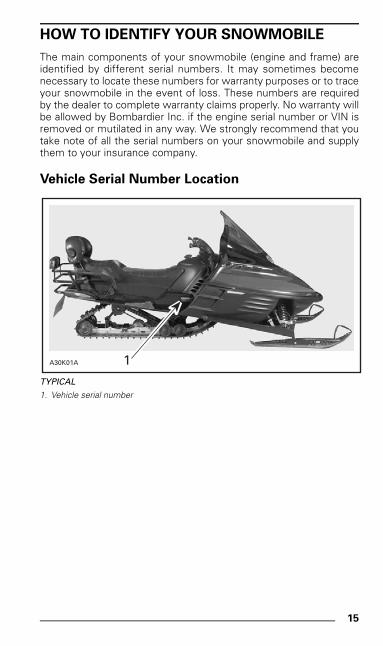
HOW TO IDENTIFY YOUR SNOWMOBILE
The main components of your snowmobile (engine and frame) areidentified by different serial numbers. It may sometimes becomenecessary to locate these numbers for warranty purposes or to traceyour snowmobile in the event of loss. These numbers are requiredby the dealer to complete warranty claims properly. No warranty willbe allowed by Bombardier Inc. if the engine serial number or VIN isremoved or mutilated in any way. We strongly recommend that youtake note of all the serial numbers on your snowmobile and supplythem to your insurance company.
Vehicle Serial Number Location
TYPICAL
1. Vehicle serial number
A30K01A 1
mmo9903a.bk : mmo9903b.fm5 Page 15 Monday, June 15, 1998 8:05 AM
16
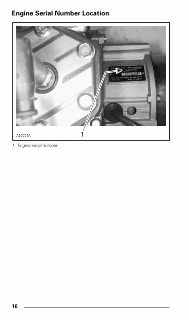
Engine Serial Number Location
1. Engine serial number
A30C01A 1
mmo9903a.bk : mmo9903b.fm5 Page 16 Monday, June 15, 1998 8:05 AM
17
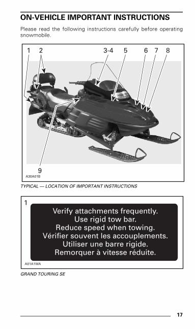
ON-VEHICLE IMPORTANT INSTRUCTIONS
Please read the following instructions carefully before operatingsnowmobile.
TYPICAL — LOCATION OF IMPORTANT INSTRUCTIONS
GRAND TOURING SE
A30A01B
2 3-4 5 6 7 8
9
1
Verify attachments frequently.Use rigid tow bar.
Reduce speed when towing.Vérifier souvent les accouplements.
Utiliser une barre rigide.Remorquer à vitesse réduite.
A01A1WA
1
mmo9903a.bk : mmo9903b.fm5 Page 17 Monday, June 15, 1998 8:05 AM
18
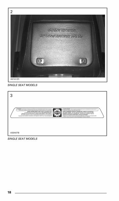
SINGLE SEAT MODELS
SINGLE SEAT MODELS
A01A1ZC
2
WARNING. Read & follow all Warning Labels & Operators Guide/Safety Handbook before operation.
Severe injury or death can result from ignoring warnings or through improper use of snowmobile.
BEFORE STARTING ENGINE, CHECK: THROTTLE LEVER MOVES FREELY-ALL GUARDS ARE IN PLACE AND CAB IS CLOSED. START ENGINE AND CHECK :
EMERGENCY CUT-OUT SWITCH AND ALL CONTROLS WORK NORMALLY. DRIVE CAREFULLY.Use of this vehicle by novice or inexperienced operator is not recommanded.
Seating on this vehicle is restricted to the operator only. Do not carry passenger(s).
AVERTISSEMENT. Lisez et respectez scrupuleusement tous les avertissements contenus dans le
Manuel du conducteur, avant toute mise en route.
AVANT DE DÉMARRER LE MOTEUR, S'ASSURER QUE: LA MANETTE D'ACCÉLÉRATEURFONCTIONNE LIBREMENT - QUE TOUT GARDE SOIT EN PLACE ET QUE LE CAPOT SOIT FERMÉDÉMARRER LE MOTEUR ET S'ASSURER QUE: L'INTERRUPTEUR D'URGENCE ET TOUS LESCONTRÔLES FONCTIONNENT NORMALEMENT. CONDUISEZ PRUDEMMENT.L'utilisation de ce véhicule n'est pas recommandée aux débutants ou autres personnes inexpérimentées
Ce véhicule n'est pas conçu pour le transport de passager(s). Conducteur seulement.
A30A07B
3
mmo9903a.bk : mmo9903b.fm5 Page 18 Monday, June 15, 1998 8:05 AM
19
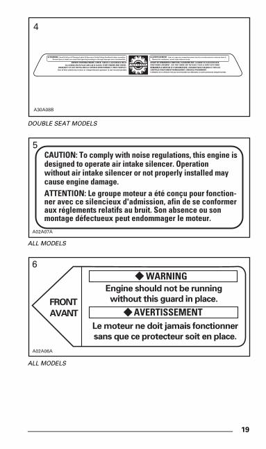
DOUBLE SEAT MODELS
ALL MODELS
ALL MODELS
WARNING. Read & follow all Warning Labels & Operators Guide/Safety Handbook before operation.
Severe injury or death can result from ignoring warnings or through improper use of snowmobile.
BEFORE STARTING ENGINE, CHECK: THROTTLE LEVER MOVES FREELY-ALL GUARDS ARE IN PLACE AND CAB IS CLOSED. START ENGINE AND CHECK :
EMERGENCY CUT-OUT SWITCH AND ALL CONTROLS WORK NORMALLY. DRIVE CAREFULLY.Use of this vehicle by novice or inexperienced operator is not recommanded.
AVERTISSEMENT. Lisez et respectez scrupuleusement tous les avertissements contenus dans le
Manuel du conducteur, avant toute mise en route.
AVANT DE DÉMARRER LE MOTEUR, S'ASSURER QUE: LA MANETTE D'ACCÉLÉRATEURFONCTIONNE LIBREMENT - QUE TOUT GARDE SOIT EN PLACE ET QUE LE CAPOT SOIT FERMÉDÉMARRER LE MOTEUR ET S'ASSURER QUE: L'INTERRUPTEUR D'URGENCE ET TOUS LESCONTRÔLES FONCTIONNENT NORMALEMENT. CONDUISEZ PRUDEMMENT.L'utilisation de ce véhicule n'est pas recommandée aux débutants ou autres personnes inexpérimentées
A30A08B
4
CAUTION: To comply with noise regulations, this engine isdesigned to operate air intake silencer. Operationwithout air intake silencer or not properly installed maycause engine damage.ATTENTION: Le groupe moteur a été conçu pour fonction-ner avec ce silencieux d'admission, afin de se conformeraux réglements relatifs au bruit. Son absence ou sonmontage défectueux peut endommager le moteur.
A02A07A
5
FRONT
AVANT
;WARNING
;AVERTISSEMENT
Engine should not be running
without this guard in place.
Le moteur ne doit jamais fonctionner
sans que ce protecteur soit en place.
A02A06A
6
mmo9903a.bk : mmo9903b.fm5 Page 19 Monday, June 15, 1998 8:05 AM
20
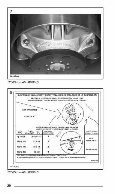
TYPICAL — ALL MODELS
TYPICAL — ALL MODELS
A01A24A
7
A01A24A
7
SUSPENSION ADJUSTMENT CHART/TABLEAU DES RÉGLAGES DE LA SUSPENSION
FRONT SUSPENSION (SKI)/SUSPENSION AVANT (SKI)ADJUST ACCORDING TO YOUR RIDING STYLE/RÉGLER SELON VOTRE CONDUITE
REAR SUSPENSION/SUSPENSION ARRIÈREADJUST ACCORDING TO LOAD/RÉGLER SELON LA CHARGE
REAR SPRING
RESSORT ARRIÈRELOAD
CHARGELB kg CENTER SPRING
RESSORT CENTRAL
NOT
APPLICABLE
SANS OBJET
1
2
3
4
up to 125 jusqu'à 57
125 to 150
150 to 175
175 to 200
57 à 68
68 à 79
79 à 91
FOR LOADS EXCEEDING RANGE SHOWN ABOVE, CONSULT YOUR DEALER.
SI LES CHARGES EXCÈDENT LES PLAGES MONTRÉES CI-HAUT, CONSULTEZ VOTRE CONCESSIONNAIRE.
418 0017 01
4 2
3
1
4
2
3
15
6
77
NOT APPLICABLE
SANS OBJET
A01A25A
8
mmo9903a.bk : mmo9903b.fm5 Page 20 Monday, June 15, 1998 8:05 AM
21
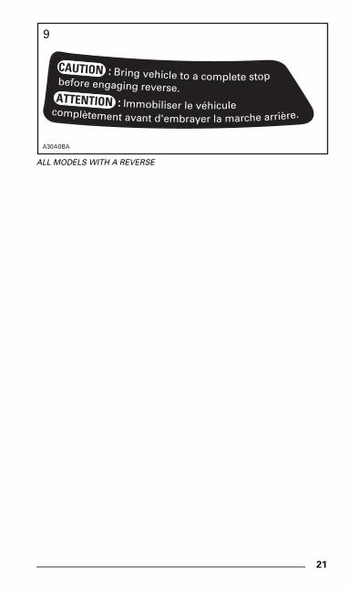
ALL MODELS WITH A REVERSE
before engaging reverse.
CAUTION : Bring vehicle to a complete stop
ATTENTION : Immobiliser le véhiculecomplètement avant d'embrayer la marche arrière.
A30A0BA
9
mmo9903a.bk : mmo9903b.fm5 Page 21 Monday, June 15, 1998 8:05 AM
22
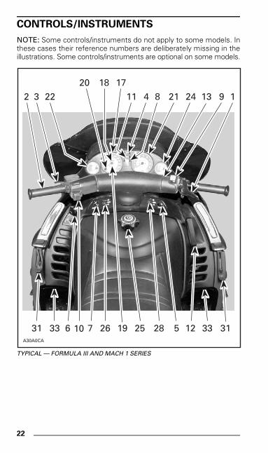
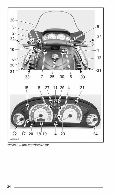
CONTROLS/INSTRUMENTS
NOTE: Some controls/instruments do not apply to some models. Inthese cases their reference numbers are deliberately missing in theillustrations. Some controls/instruments are optional on some models.
TYPICAL — FORMULA III AND MACH 1 SERIES
A30A0CA
32 22
20 17
21 24
18
8411 1
31 33 26 25 28 5 33 3176 12
9
1910
13
mmo9903a.bk : mmo9903b.fm5 Page 22 Monday, June 15, 1998 8:05 AM
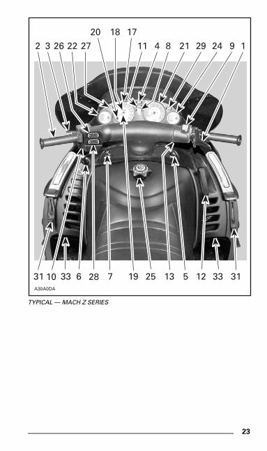
23
TYPICAL — MACH Z SERIES
A30A0DA
32 22 27
20 17
21 29 24
18
8411 1
31 33 25 513 33 3176 12
9
192810
26
mmo9903a.bk : mmo9903b.fm5 Page 23 Monday, June 15, 1998 8:05 AM
24
TYPICAL — GRAND TOURING 700
P
26
9
22
15
3
232
10
628
3133
A30A0JA
32
1
30
12
31
33
8 27 11 29 4 21
17 20 18-19 234 24
5257
mmo9903a.bk : mmo9903b.fm5 Page 24 Monday, June 15, 1998 8:05 AM
25
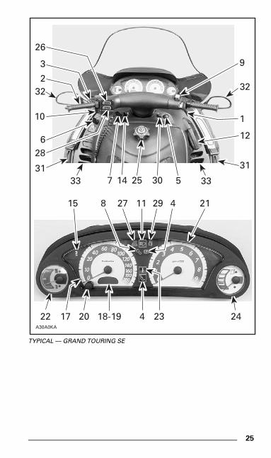
TYPICAL — GRAND TOURING SE
P
26
9
22
15
3
232
10
628
3133
A30A0KA
32
1
30
12
31
33
8 27 11 29 4 21
17 20 18-19 234 24
5257 14
mmo9903a.bk : mmo9903b.fm5 Page 25 Monday, June 15, 1998 8:05 AM
26
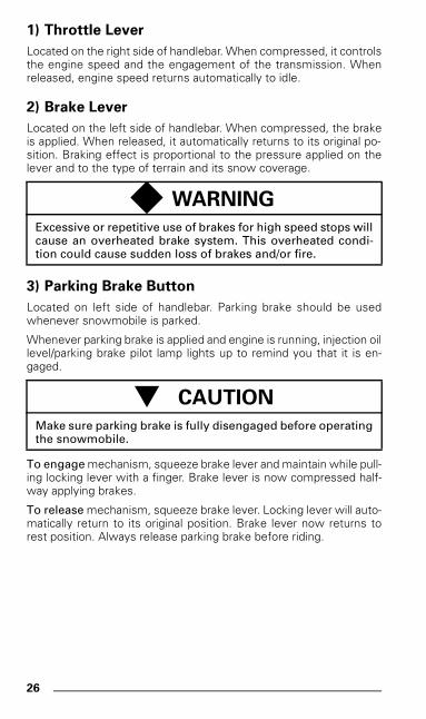
1) Throttle Lever
Located on the right side of handlebar. When compressed, it controlsthe engine speed and the engagement of the transmission. Whenreleased, engine speed returns automatically to idle.
2) Brake Lever
Located on the left side of handlebar. When compressed, the brakeis applied. When released, it automatically returns to its original po-sition. Braking effect is proportional to the pressure applied on thelever and to the type of terrain and its snow coverage.
3) Parking Brake Button
Located on left side of handlebar. Parking brake should be usedwhenever snowmobile is parked.
Whenever parking brake is applied and engine is running, injection oillevel/parking brake pilot lamp lights up to remind you that it is en-gaged.
To engage mechanism, squeeze brake lever and maintain while pull-ing locking lever with a finger. Brake lever is now compressed half-way applying brakes.
To release mechanism, squeeze brake lever. Locking lever will auto-matically return to its original position. Brake lever now returns torest position. Always release parking brake before riding.
◆ WARNING
Excessive or repetitive use of brakes for high speed stops willcause an overheated brake system. This overheated condi-tion could cause sudden loss of brakes and/or fire.
- CAUTION
Make sure parking brake is fully disengaged before operatingthe snowmobile.
mmo9903a.bk : mmo9903b.fm5 Page 26 Monday, June 15, 1998 8:05 AM
27
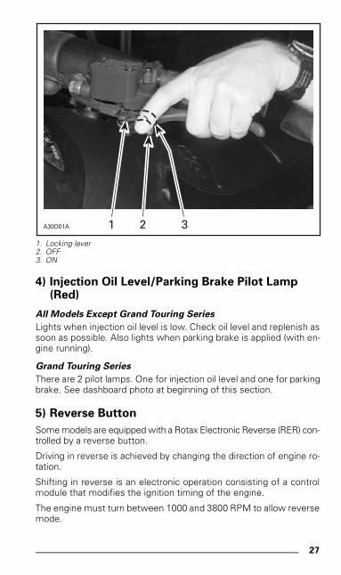
1. Locking lever2. OFF3. ON
4) Injection Oil Level/Parking Brake Pilot Lamp (Red)
All Models Except Grand Touring Series
Lights when injection oil level is low. Check oil level and replenish assoon as possible. Also lights when parking brake is applied (with en-gine running).
Grand Touring Series
There are 2 pilot lamps. One for injection oil level and one for parkingbrake. See dashboard photo at beginning of this section.
5) Reverse Button
Some models are equipped with a Rotax Electronic Reverse (RER) con-trolled by a reverse button.
Driving in reverse is achieved by changing the direction of engine ro-tation.
Shifting in reverse is an electronic operation consisting of a controlmodule that modifies the ignition timing of the engine.
The engine must turn between 1000 and 3800 RPM to allow reversemode.
A30D01A 1 2 3
mmo9903a.bk : mmo9903b.fm5 Page 27 Monday, June 15, 1998 8:05 AM
28
When depressing the reverse button, a signal will slow down theengine RPM enough to modify the ignition timing advance. This re-verses crankshaft rotation.
No mechanical action and gear change is involved.
No adjustment is needed except for high altitude. See RER Opera-tion at High Altitude below.
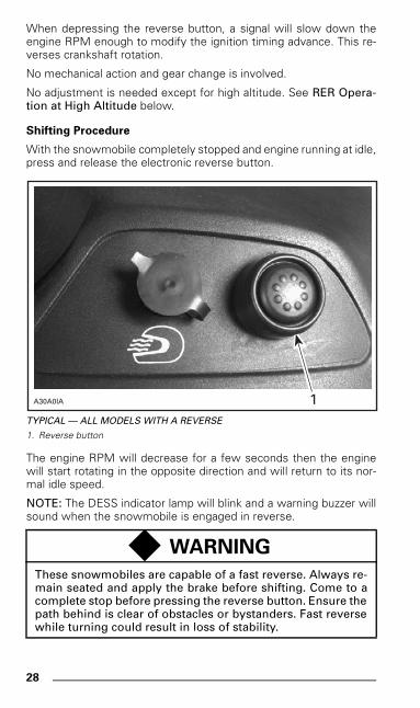
Shifting Procedure
With the snowmobile completely stopped and engine running at idle,press and release the electronic reverse button.
TYPICAL — ALL MODELS WITH A REVERSE
1. Reverse button
The engine RPM will decrease for a few seconds then the enginewill start rotating in the opposite direction and will return to its nor-mal idle speed.
NOTE: The DESS indicator lamp will blink and a warning buzzer willsound when the snowmobile is engaged in reverse.
◆ WARNING
These snowmobiles are capable of a fast reverse. Always re-main seated and apply the brake before shifting. Come to acomplete stop before pressing the reverse button. Ensure thepath behind is clear of obstacles or bystanders. Fast reversewhile turning could result in loss of stability.
1A30A0IA
mmo9903a.bk : mmo9903b.fm5 Page 28 Monday, June 15, 1998 8:05 AM
29
Apply throttle slowly and evenly. Allow drive pulley to engage thenaccelerate carefully.
It is recommended to warm up the engine to its normal operatingtemperature before shifting.
Shifting procedure will take place only when the engine is running.
Engine will automatically shift into forward when starting after stop-ping or stalling.
RER Operation at High Altitude
General
At high altitude, the RER system needs a different engine timingcurve to work properly.
Operation
Mach 1 R, Mach Z R and Mach Z LT R
Before using the reverse system, first select the altitude mode thatchanges engine timing curve.
To do so, push and hold reverse button with engine running. After 2seconds, one beep is heard meaning that the low altitude mode canbe selected. Releasing button just after hearing that one beep willselect the low altitude mode. The reverse system is now ready tooperate in low altitude regions. Shifting in reverse is achieved as de-scribed above in Shifting Procedure.
To select high altitude mode, push and hold reverse button until 2beeps are heard. Release button within one second. The reversesystem is now ready to operate in high altitude regions. Shifting inreverse is achieved as described above in Shifting Procedure.
As long as the reverse button is pushed and held the RER systemswitches from one mode to the other. One beep then 2 beeps thenone beep then 2 beeps and so on are heard with one second interval.The mode to be selected corresponds to the last beep code heard.
The selected altitude mode is kept in memory until a new one ischosen — whether the engine is stopped or not.
Grand Touring 700/SE
These vehicles are equipped with a Digital Performance Manage-ment (DPM) system. This system takes care of the altitude moderequired by the RER.
- CAUTION
Do not rev the engine when driving in reverse. This maycause the clutch system to operate erratically.
mmo9903a.bk : mmo9903b.fm5 Page 29 Monday, June 15, 1998 8:05 AM
30
No reverse button operation is needed to select a mode. Just followShifting Procedure above.
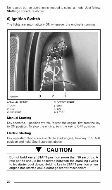
6) Ignition Switch
The lights are automatically ON whenever the engine is running.
MANUAL START ELECTRIC START
1. OFF 1. OFF2. ON 2. ON3. Not used 3. START
Manual Starting
Key operated, 3-position switch. To start the engine, first turn the keyto ON position. To stop the engine, turn the key to OFF position.
Electric Starting
Key operated, 3-position switch. To start engine, turn key to STARTposition and hold. See illustration above.
- CAUTION
Do not hold key at START position more than 30 seconds. Arest period should be observed between the cranking cyclesto let starter cool down. Holding key in START position whenengine has started could damage starter mechanism.
A30H07A 123
mmo9903a.bk : mmo9903b.fm5 Page 30 Monday, June 15, 1998 8:05 AM
31
Release key immediately when engine has started. Key returns toON position as soon as it is released.
If engine does not start on first try, turn key back to OFF positionbefore restarting. To stop engine, turn key to OFF position.
NOTE: Engine may be manually started with rewind starter if neces-sary.
If starter does not operate, check starting system fuse condition.Refer to Starting System Fuse below.
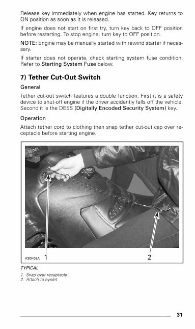
7) Tether Cut-Out Switch
General
Tether cut-out switch features a double function. First it is a safetydevice to shut-off engine if the driver accidently falls off the vehicle.Second it is the DESS (Digitally Encoded Security System) key.
Operation
Attach tether cord to clothing then snap tether cut-out cap over re-ceptacle before starting engine.
TYPICAL
1. Snap over receptacle2. Attach to eyelet
A30H09A 1 2
mmo9903a.bk : mmo9903b.fm5 Page 31 Monday, June 15, 1998 8:05 AM
32
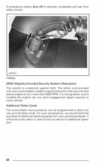
If emergency engine shut off is required, completely pull cap fromsafety switch.
TYPICAL
DESS (Digitally Encoded Security System) Description
This system is a deterrent against theft. The tether cord providedwith your snowmobile is dealer programmed and is the only one thatallows engine to turn more than 3000 RPM. If a wrong tether cord isinstalled the engine can not reach engagement speed required tomove vehicle.
Additional Tether Cords
The snowmobile micro-processor can be programmed to allow theuse up to 8 tether cords. For your convenience, we recommend thepurchase of additional safety lanyards from your authorized dealer. Itwill prove to be useful in case of loss as well as for additional opera-tors.
A30H0AA
mmo9903a.bk : mmo9903b.fm5 Page 32 Monday, June 15, 1998 8:05 AM
33
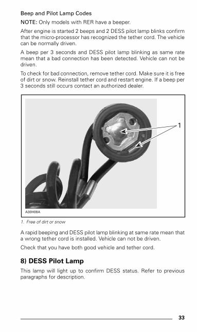
Beep and Pilot Lamp Codes
NOTE: Only models with RER have a beeper.
After engine is started 2 beeps and 2 DESS pilot lamp blinks confirmthat the micro-processor has recognized the tether cord. The vehiclecan be normally driven.
A beep per 3 seconds and DESS pilot lamp blinking as same ratemean that a bad connection has been detected. Vehicle can not bedriven.
To check for bad connection, remove tether cord. Make sure it is freeof dirt or snow. Reinstall tether cord and restart engine. If a beep per3 seconds still occurs contact an authorized dealer.
1. Free of dirt or snow
A rapid beeping and DESS pilot lamp blinking at same rate mean thata wrong tether cord is installed. Vehicle can not be driven.
Check that you have both good vehicle and tether cord.
8) DESS Pilot Lamp
This lamp will light up to confirm DESS status. Refer to previousparagraphs for description.
A30H08A
1
mmo9903a.bk : mmo9903b.fm5 Page 33 Monday, June 15, 1998 8:05 AM
34
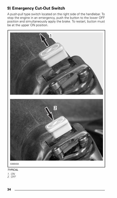
9) Emergency Cut-Out Switch
A push-pull type switch located on the right side of the handlebar. Tostop the engine in an emergency, push the button to the lower OFFposition and simultaneously apply the brake. To restart, button mustbe at the upper ON position.
TYPICAL
1. ON2. OFF
A30E03A
2
1
mmo9903a.bk : mmo9903b.fm5 Page 34 Monday, June 15, 1998 8:05 AM
35
All drivers of the snowmobile should familiarize themselves with thefunction of this device by using it several times on first outing and tostop the engine there after. Thereby being mentally prepared foremergency situations requiring its use.
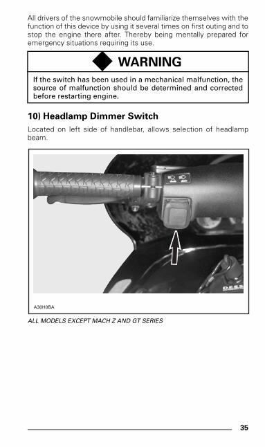
10) Headlamp Dimmer Switch
Located on left side of handlebar, allows selection of headlampbeam.
ALL MODELS EXCEPT MACH Z AND GT SERIES
◆ WARNING
If the switch has been used in a mechanical malfunction, thesource of malfunction should be determined and correctedbefore restarting engine.
A30H0BA
mmo9903a.bk : mmo9903b.fm5 Page 35 Monday, June 15, 1998 8:05 AM
36
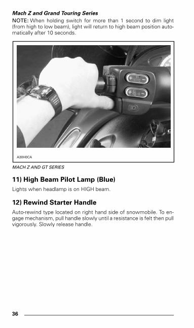
Mach Z and Grand Touring Series
NOTE: When holding switch for more than 1 second to dim light(from high to low beam), light will return to high beam position auto-matically after 10 seconds.
MACH Z AND GT SERIES
11) High Beam Pilot Lamp (Blue)
Lights when headlamp is on HIGH beam.
12) Rewind Starter Handle
Auto-rewind type located on right hand side of snowmobile. To en-gage mechanism, pull handle slowly until a resistance is felt then pullvigorously. Slowly release handle.
A30H0CA
mmo9903a.bk : mmo9903b.fm5 Page 36 Monday, June 15, 1998 8:05 AM
37
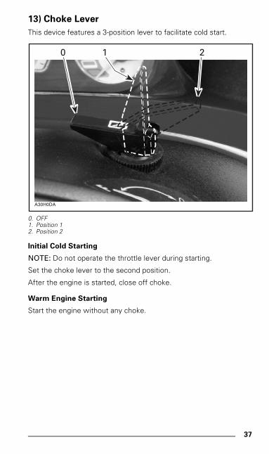
13) Choke Lever
This device features a 3-position lever to facilitate cold start.
0. OFF1. Position 12. Position 2
Initial Cold Starting
NOTE: Do not operate the throttle lever during starting.
Set the choke lever to the second position.
After the engine is started, close off choke.
Warm Engine Starting
Start the engine without any choke.
A30H0DA
0 1 2
mmo9903a.bk : mmo9903b.fm5 Page 37 Monday, June 15, 1998 8:05 AM
38
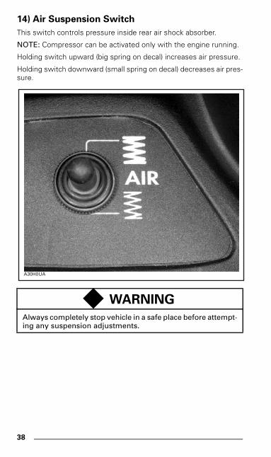
14) Air Suspension Switch
This switch controls pressure inside rear air shock absorber.
NOTE: Compressor can be activated only with the engine running.
Holding switch upward (big spring on decal) increases air pressure.
Holding switch downward (small spring on decal) decreases air pres-sure.
.
◆ WARNING
Always completely stop vehicle in a safe place before attempt-ing any suspension adjustments.
A30H0UA
mmo9903a.bk : mmo9903b.fm5 Page 38 Monday, June 15, 1998 8:05 AM
39
15) Air Suspension Pilot Lamp
This pilot lamp lights up each time the air suspension switch is used.
This pilot lamp also lights up each time compressor runs becausepressure has reached low level threshold.
16) Air Suspension Gauge
This gauge indicates comfort level (pressure inside rear air shock ab-sorber).
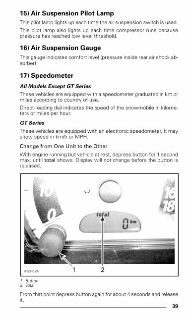
17) Speedometer
All Models Except GT Series
These vehicles are equipped with a speedometer graduated in km ormiles according to country of use.
Direct-reading dial indicates the speed of the snowmobile in kilome-ters or miles per hour.
GT Series
These vehicles are equipped with an electronic speedometer. It mayshow speed in km/h or MPH.
Change from One Unit to the Other
With engine running but vehicle at rest, depress button for 1 secondmax. until total shows. Display will not change before the button isreleased.
1. Button2. Total
From that point depress button again for about 4 seconds and releaseit.
A30H0VA 1 2
mmo9903a.bk : mmo9903b.fm5 Page 39 Monday, June 15, 1998 8:05 AM
40
18) Odometer
All Models Except GT Series
Odometer records the total distance travelled in kilometers or miles.
GT Series
With engine running but vehicle at rest, depress button for 1 secondmax. until total shows. Display will not change before the button isreleased.
Odometer records the total distance travelled in kilometers or miles.See above for changing units.
When riding at 140 km/h (87 MPH) or faster, display will indicatespeed instead of total distance.
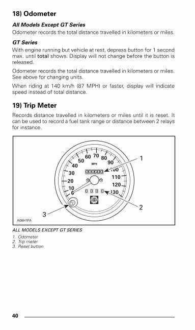
19) Trip Meter
Records distance travelled in kilometers or miles until it is reset. Itcan be used to record a fuel tank range or distance between 2 relaysfor instance.
ALL MODELS EXCEPT GT SERIES
1. Odometer2. Trip meter3. Reset button
100
20
30
4050
60 70 8090
100
110
120
130
000000
0 0 0 0
MPH
1
23
A06H1FA
mmo9903a.bk : mmo9903b.fm5 Page 40 Monday, June 15, 1998 8:05 AM
41
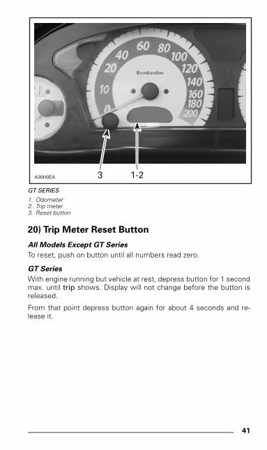
GT SERIES
1. Odometer2. Trip meter3. Reset button
20) Trip Meter Reset Button
All Models Except GT Series
To reset, push on button until all numbers read zero.
GT Series
With engine running but vehicle at rest, depress button for 1 secondmax. until trip shows. Display will not change before the button isreleased.
From that point depress button again for about 4 seconds and re-lease it.
A30H0EA 3 1-2
mmo9903a.bk : mmo9903b.fm5 Page 41 Monday, June 15, 1998 8:05 AM
42
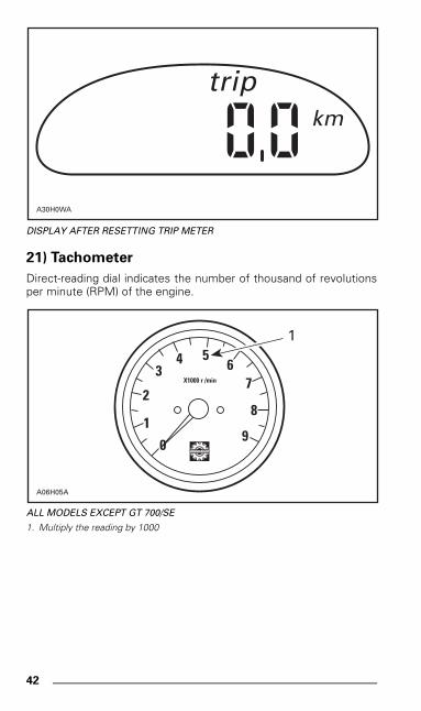
DISPLAY AFTER RESETTING TRIP METER
21) Tachometer
Direct-reading dial indicates the number of thousand of revolutionsper minute (RPM) of the engine.
ALL MODELS EXCEPT GT 700/SE
1. Multiply the reading by 1000
tripkm
A30H0WA
2
1
34 6
5
7
8
90
X1000 r /min
1
A06H05A
mmo9903a.bk : mmo9903b.fm5 Page 42 Monday, June 15, 1998 8:05 AM
43
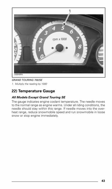
GRAND TOURING 700/SE
1. Multiply the reading by 1000
22) Temperature Gauge
All Models Except Grand Touring SE
The gauge indicates engine coolant temperature. The needle movesto the normal range as engine warms. Under all riding conditions, theneedle should stay within this range. If needle moves into the over-heat range, reduce snowmobile speed and run snowmobile in loosesnow or stop engine immediately.
A30H0FA
1
mmo9903a.bk : mmo9903b.fm5 Page 43 Monday, June 15, 1998 8:05 AM
44
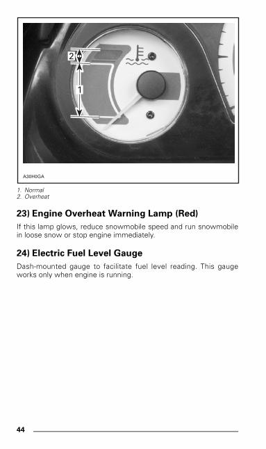
1. Normal2. Overheat
23) Engine Overheat Warning Lamp (Red)
If this lamp glows, reduce snowmobile speed and run snowmobilein loose snow or stop engine immediately.
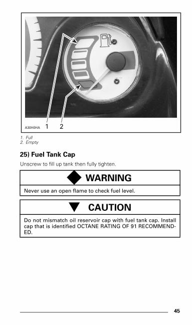
24) Electric Fuel Level Gauge
Dash-mounted gauge to facilitate fuel level reading. This gaugeworks only when engine is running.
A30H0GA
2
1
mmo9903a.bk : mmo9903b.fm5 Page 44 Monday, June 15, 1998 8:05 AM
45
1. Full2. Empty
25) Fuel Tank Cap
Unscrew to fill up tank then fully tighten.
◆ WARNING
Never use an open flame to check fuel level.
- CAUTION
Do not mismatch oil reservoir cap with fuel tank cap. Installcap that is identified OCTANE RATING OF 91 RECOMMEND-ED.
A30H0HA 1 2
mmo9903a.bk : mmo9903b.fm5 Page 45 Monday, June 15, 1998 8:05 AM
46
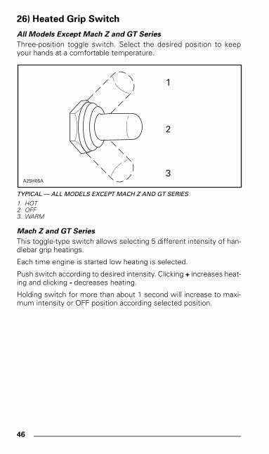
26) Heated Grip Switch
All Models Except Mach Z and GT Series
Three-position toggle switch. Select the desired position to keepyour hands at a comfortable temperature.
TYPICAL — ALL MODELS EXCEPT MACH Z AND GT SERIES
1. HOT2. OFF3. WARM
Mach Z and GT Series
This toggle-type switch allows selecting 5 different intensity of han-dlebar grip heatings.
Each time engine is started low heating is selected.
Push switch according to desired intensity. Clicking + increases heat-ing and clicking - decreases heating.
Holding switch for more than about 1 second will increase to maxi-mum intensity or OFF position according selected position.
1
2
3A25H05A
mmo9903a.bk : mmo9903b.fm5 Page 46 Monday, June 15, 1998 8:05 AM
47
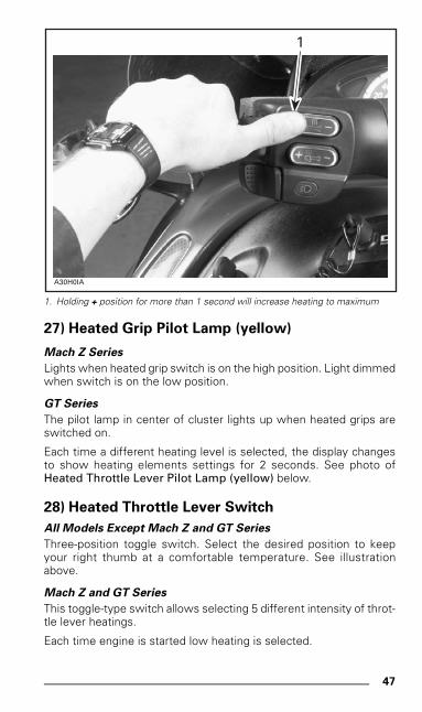
1. Holding + position for more than 1 second will increase heating to maximum
27) Heated Grip Pilot Lamp (yellow)
Mach Z Series
Lights when heated grip switch is on the high position. Light dimmedwhen switch is on the low position.
GT Series
The pilot lamp in center of cluster lights up when heated grips areswitched on.
Each time a different heating level is selected, the display changesto show heating elements settings for 2 seconds. See photo ofHeated Throttle Lever Pilot Lamp (yellow) below.
28) Heated Throttle Lever Switch
All Models Except Mach Z and GT Series
Three-position toggle switch. Select the desired position to keepyour right thumb at a comfortable temperature. See illustrationabove.
Mach Z and GT Series
This toggle-type switch allows selecting 5 different intensity of throt-tle lever heatings.
Each time engine is started low heating is selected.
A30H0IA
1
mmo9903a.bk : mmo9903b.fm5 Page 47 Monday, June 15, 1998 8:05 AM
48
Push switch according to desired intensity. Holding + increases heat-ing and holding - decreases heating.
Holding switch for more than about 1 second will increase to maxi-mum intensity or OFF position according selected position.
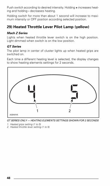
29) Heated Throttle Lever Pilot Lamp (yellow)
Mach Z Series
Lights when heated throttle lever switch is on the high position.Light dimmed when switch is on the low position.
GT Series
The pilot lamp in center of cluster lights up when heated grips areswitched on.
Each time a different heating level is selected, the display changesto show heating elements settings for 2 seconds.
GT SERIES ONLY — HEATING ELEMENTS SETTINGS SHOWN FOR 2 SECONDS
1. Heated grips setting (1 to 5)2. Heated throttle lever setting (1 to 5)
A30H0YA
1 2
mmo9903a.bk : mmo9903b.fm5 Page 48 Monday, June 15, 1998 8:05 AM
49
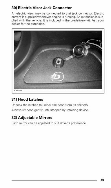
30) Electric Visor Jack Connector
An electric visor may be connected to that jack connector. Electriccurrent is supplied whenever engine is running. An extension is sup-plied with the vehicle. It is included in the predelivery kit. Ask yourdealer for the extension.
31) Hood Latches
Unhook the latches to unlock the hood from its anchors.
Always lift hood gently until stopped by retaining device.
32) Adjustable Mirrors
Each mirror can be adjusted to suit driver's preference.
A30E09A
mmo9903a.bk : mmo9903b.fm5 Page 49 Monday, June 15, 1998 8:05 AM
50
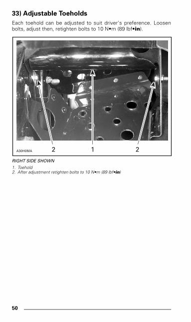
33) Adjustable Toeholds
Each toehold can be adjusted to suit driver's preference. Loosenbolts, adjust then, retighten bolts to 10 N•m (89 lbf•in).
RIGHT SIDE SHOWN
1. Toehold2. After adjustment retighten bolts to 10 N•m (89 lbf•in)
A30H0MA 1 22
mmo9903a.bk : mmo9903b.fm5 Page 50 Monday, June 15, 1998 8:05 AM
51
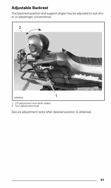
Adjustable Backrest
The backrest position and support angle may be adjusted to suit driv-er or passenger convenience.
1. Lift adjustment lock (both sides)2. Turn adjustment knob
Secure adjustment locks after desired position is obtained.
A30H0OA1
2
mmo9903a.bk : mmo9903b.fm5 Page 51 Monday, June 15, 1998 8:05 AM
52
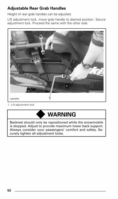
Adjustable Rear Grab Handles
Height of rear grab handles can be adjusted.
Lift adjustment lock, move grab handle to desired position. Secureadjustment lock. Proceed the same with the other side.
1. Lift adjustment lock
◆ WARNING
Backrest should only be repositioned while the snowmobileis stopped. Adjust to provide maximum lower back support.Always consider your passengers’ comfort and safety. Se-curely tighten all adjustment locks.
A30H0PA 1
mmo9903a.bk : mmo9903b.fm5 Page 52 Monday, June 15, 1998 8:05 AM
53
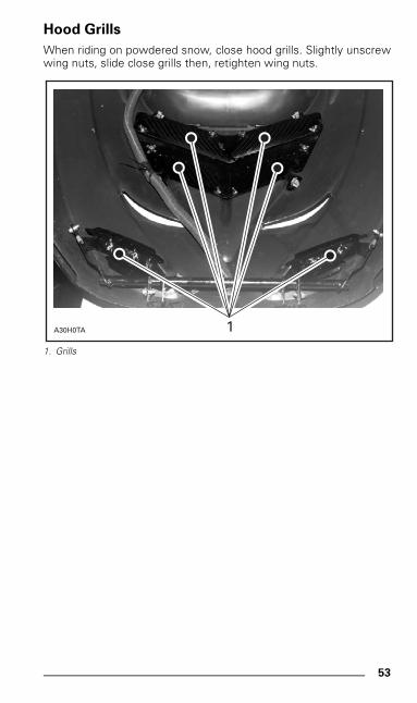
Hood Grills
When riding on powdered snow, close hood grills. Slightly unscrewwing nuts, slide close grills then, retighten wing nuts.
1. Grills
A30H0TA 1
mmo9903a.bk : mmo9903b.fm5 Page 53 Monday, June 15, 1998 8:05 AM
54
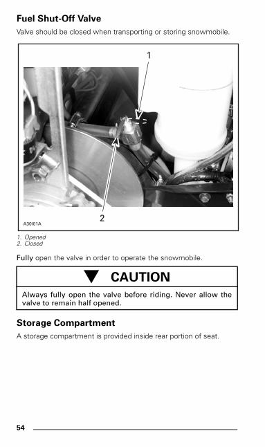
Fuel Shut-Off Valve
Valve should be closed when transporting or storing snowmobile.
1. Opened2. Closed
Fully open the valve in order to operate the snowmobile.
Storage Compartment
A storage compartment is provided inside rear portion of seat.
- CAUTION
Always fully open the valve before riding. Never allow thevalve to remain half opened.
A30I01A
1
2
mmo9903a.bk : mmo9903b.fm5 Page 54 Monday, June 15, 1998 8:05 AM
55
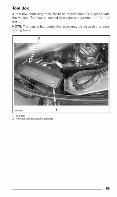
Tool Box
A tool box containing tools for basic maintenance is supplied withthe vehicle. Tool box is located in engine compartment in front ofguard.
NOTE: The plastic bag containing tools may be discarded to easestoring tools.
1. Tool box2. Remove hair pin before opening
A30D0PA 1
2
mmo9903a.bk : mmo9903b.fm5 Page 55 Monday, June 15, 1998 8:05 AM
56
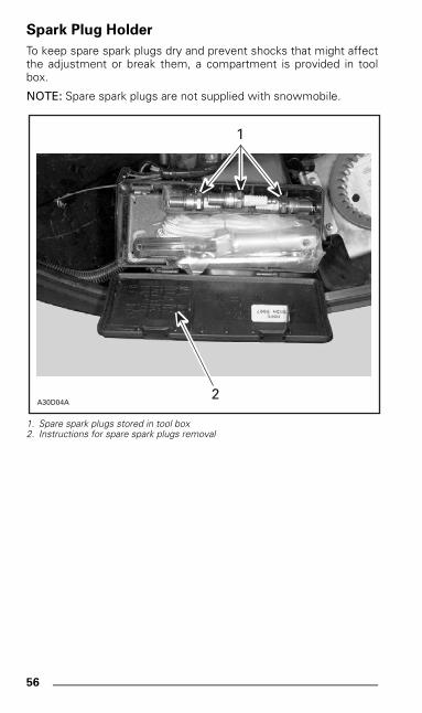
Spark Plug Holder
To keep spare spark plugs dry and prevent shocks that might affectthe adjustment or break them, a compartment is provided in toolbox.
NOTE: Spare spark plugs are not supplied with snowmobile.
1. Spare spark plugs stored in tool box2. Instructions for spare spark plugs removal
A30D04A
1
2
mmo9903a.bk : mmo9903b.fm5 Page 56 Monday, June 15, 1998 8:05 AM
57
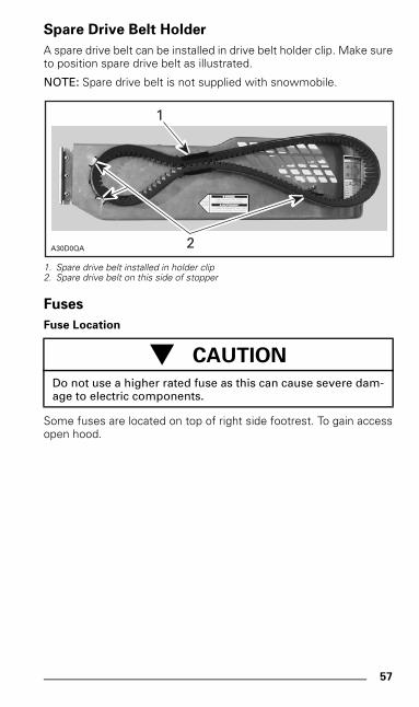
Spare Drive Belt Holder
A spare drive belt can be installed in drive belt holder clip. Make sureto position spare drive belt as illustrated.
NOTE: Spare drive belt is not supplied with snowmobile.
1. Spare drive belt installed in holder clip2. Spare drive belt on this side of stopper
Fuses
Fuse Location
Some fuses are located on top of right side footrest. To gain accessopen hood.
- CAUTION
Do not use a higher rated fuse as this can cause severe dam-age to electric components.
A30D0QA 2
1
mmo9903a.bk : mmo9903b.fm5 Page 57 Monday, June 15, 1998 8:05 AM
58
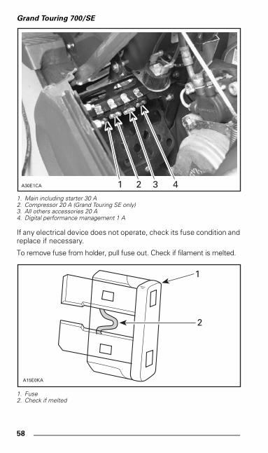
Grand Touring 700/SE
1. Main including starter 30 A2. Compressor 20 A (Grand Touring SE only)3. All others accessories 20 A4. Digital performance management 1 A
If any electrical device does not operate, check its fuse condition andreplace if necessary.
To remove fuse from holder, pull fuse out. Check if filament is melted.
1. Fuse2. Check if melted
1A30E1CA 2 3 4
1
2
A15E0KA
mmo9903a.bk : mmo9903b.fm5 Page 58 Monday, June 15, 1998 8:05 AM
59
Electric Fuel Level Gauge Fuse
See your dealer for fuse replacement.
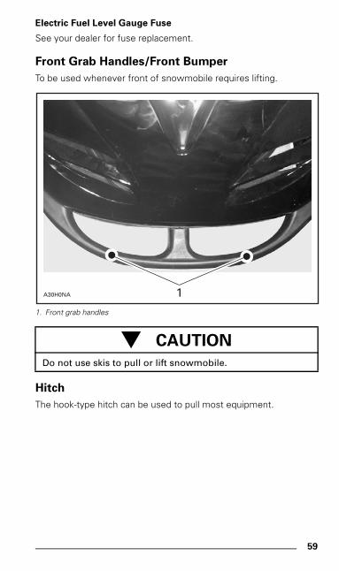
Front Grab Handles/Front Bumper
To be used whenever front of snowmobile requires lifting.
1. Front grab handles
Hitch
The hook-type hitch can be used to pull most equipment.
- CAUTION
Do not use skis to pull or lift snowmobile.
A30H0NA 1
mmo9903a.bk : mmo9903b.fm5 Page 59 Monday, June 15, 1998 8:05 AM
60
FUEL AND OIL
Recommended Fuel
Use super unleaded gasoline, available from most service stations orgasohol containing less than 10% of ethanol or methanol. The fuelused must have an octane number (R + M)/2 of 91 or higher.
NOTE: In most service station pump octane number corresponds to(R + M)/2 octane number.
Recommended Oil
- CAUTION
Never experiment with other fuels. The use of unrecom-mended fuel can result in snowmobile performance deterio-ration and damage to critical parts in the fuel system andengine components. Do not mismatch oil reservoir cap withfuel tank cap. Install cap that is identified OCTANE RATINGOF 91 RECOMMENDED.
◆ WARNING
Never top up the fuel tank before placing the snowmobile ina warm area. As temperature increases, fuel expands andmight overflow. Fuel is flammable and explosive under cer-tain conditions. Always wipe off any fuel or oil spillage fromthe snowmobile.
- CAUTION
Never mix brands of 2-cycle oil as chemical reaction cancause engine damage. Never use outboard or straight miner-al oils. Use only oil that flows at -40°C (-40°F). Do not mis-match oil reservoir cap with fuel tank cap. Install cap that isidentified OIL.
mmo9903a.bk : mmo9903b.fm5 Page 60 Monday, June 15, 1998 8:05 AM
61
Oil is contained in the oil injection reservoir.
Use BOMBARDIER-ROTAX INJECTION OIL (P/N 413 802 900 — 12x 1 liter) available from authorized dealer. This type of oil will flow attemperatures as low as minus 40°C (-40°F). If unavailable, substitutewith BOMBARDIER-ROTAX PRE-MIX OIL (P/N 413 803 100 — 12 x500 mL).
Always maintain a sufficient amount of recommended oil in the in-jection oil reservoir.
COLD WEATHER CARBURETION MODIFICATIONS
All vehicles have been calibrated for -20°C (-4°F). They can be oper-ated at higher temperature without problems.
- CAUTION
Check level and refill every time you refuel. Wipe off any oilspills. Oil is highly flammable. Do not mismatch oil reservoircap with fuel tank cap. Install cap that is identified OIL.
- CAUTION
For colder temperatures than -20°C (-4°F), carburetor(s) mustbe recalibrated to avoid engine damage. Refer to an autho-rized dealer.
mmo9903a.bk : mmo9903b.fm5 Page 61 Monday, June 15, 1998 8:05 AM
62
BREAK-IN PERIOD
Engine
A break-in period of 10 to 15 operating hours — 500 km (300 mi) —is required before running the snowmobile at full throttle.
During this period, maximum throttle should not exceed 3/4. How-ever, brief full acceleration and speed variations contribute to agood break-in. Continued wide open throttle accelerations, pro-longed cruising speeds and engine overheating are detrimental dur-ing the break-in period.
To assure additional protection during the initial engine break-in, 500 mL(18 imp. oz) of BOMBARDIER-ROTAX INJECTION OIL (P/N 413 802900 — 12 x 1 liter), should be added to fuel for the first full filling offuel tank. Always remove and clean spark plugs after engine break-in.
Belt
A new drive belt requires a break-in period of 50 km (30 miles). Avoidstrong acceleration/deceleration, pulling a load or high speed cruis-ing.
10-Hour Inspection
As with any precision piece of mechanical equipment, we suggestthat after the first 10 hours of operation — 500 km (300 mi) — or 30days after the purchase, whichever comes first, your snowmobile bechecked by an authorized dealer. This inspection will give you theopportunity to discuss the unanswered questions you may have en-countered during the first hours of operation.
The 10-hour inspection is at the expense of the snowmobileowner.
mmo9903a.bk : mmo9903b.fm5 Page 62 Monday, June 15, 1998 8:05 AM
63
PRE-START CHECK
Check Points
• Activate the throttle control lever several times to check that itoperates easily and smoothly. It must return to idle position whenreleased.
• Activate the brake control lever and make sure the brake fully ap-plies before the brake control lever touches the handlebar grip. Itmust fully return when released.
• Verify skis and steering operate freely.
• Verify track and idler wheels are unfrozen and free to turn.
• Check fuel and injection oil level.
• Ensure fuel shut-off valve is in fully open position.
• Verify air filter(s) is free of snow, if so equipped.
• Clean and check operation of the headlight, taillight and brakelight.
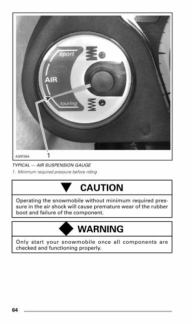
• Make sure that air suspension gauge indicates first mark. Seephoto below. Activate air suspension switch to obtain the mini-mum required pressure before operating the snowmobile.
mmo9903a.bk : mmo9903b.fm5 Page 63 Monday, June 15, 1998 8:05 AM
64
TYPICAL — AIR SUSPENSION GAUGE
1. Minimum required pressure before riding
- CAUTION
Operating the snowmobile without minimum required pres-sure in the air shock will cause premature wear of the rubberboot and failure of the component.
◆ WARNING
Only start your snowmobile once all components arechecked and functioning properly.
1A30F06A
mmo9903a.bk : mmo9903b.fm5 Page 64 Monday, June 15, 1998 8:05 AM
65
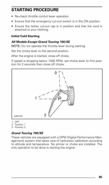
STARTING PROCEDURE
• Re-check throttle control lever operation.
• Ensure that the emergency cut-out switch is in the ON position.
• Ensure the tether cut-out cap is in position and that the cord isattached to your clothing.
Initial Cold Starting
All Models Except Grand Touring 700/SE
NOTE: Do not operate the throttle lever during starting.
Set the choke lever to the second position.
After the engine is started, close off choke.
If speed is dropping below 1500 RPM, set choke lever to first posi-tion for 2 seconds then close off choke.
1. OFF2. Position 13. Position 2
Grand Touring 700/SE
These vehicles are equipped with a DPM (Digital Performance Man-agement) system that takes care of carburetor calibration accordingto altitude and temperature. No primer or choke are installed. Theonly operation to be done is starting the engine.
0
1
2A06H1KB
mmo9903a.bk : mmo9903b.fm5 Page 65 Monday, June 15, 1998 8:05 AM
66
Warm Engine Starting
All Models Except Grand Touring 700/SE
Start the engine without any choke.
Grand Touring 700/SE
These vehicles are equipped with a DPM system. The only operationto be done is starting the engine.
Manual Starting
Insert the key in the ignition switch and turn to ON position.
Grasp manual starter handle firmly and crank engine.
Electric Starting (some models only)
Insert key in ignition switch.
Turn key clockwise until starter engages.
Release key immediately when engine has started.
NOTE: If for any reason, the snowmobile cannot be started electri-cally, place ignition key to ON position and start engine manually.
Emergency Starting
The engine can be started with the emergency starter rope suppliedwith the tool kit.
Remove guard.
◆ WARNING
Do not apply throttle while starting.
◆ WARNING
Do not wind starting rope around your hand. Hold rope bythe handle only. Do not start the snowmobile by the drivepulley unless it is a true emergency situation. Have the snow-mobile repaired as soon as possible.
mmo9903a.bk : mmo9903b.fm5 Page 66 Monday, June 15, 1998 8:05 AM
67
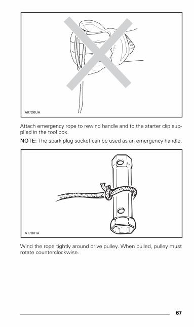
Attach emergency rope to rewind handle and to the starter clip sup-plied in the tool box.
NOTE: The spark plug socket can be used as an emergency handle.
Wind the rope tightly around drive pulley. When pulled, pulley mustrotate counterclockwise.
A07D0UA
A17B01A
mmo9903a.bk : mmo9903b.fm5 Page 67 Monday, June 15, 1998 8:05 AM
68
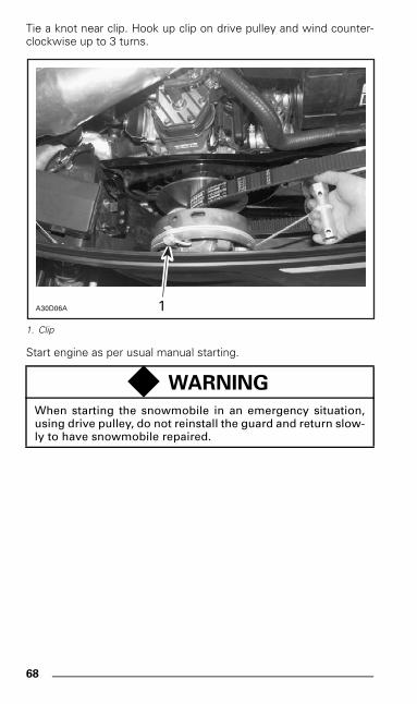
Tie a knot near clip. Hook up clip on drive pulley and wind counter-clockwise up to 3 turns.
1. Clip
Start engine as per usual manual starting.
◆ WARNING
When starting the snowmobile in an emergency situation,using drive pulley, do not reinstall the guard and return slow-ly to have snowmobile repaired.
A30D06A 1
mmo9903a.bk : mmo9903b.fm5 Page 68 Monday, June 15, 1998 8:05 AM
69
SUSPENSION ADJUSTMENTS
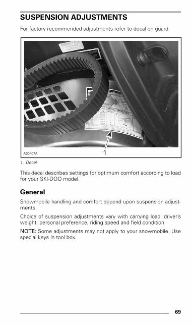
For factory recommended adjustments refer to decal on guard.
1. Decal
This decal describes settings for optimum comfort according to loadfor your SKI-DOO model.
General
Snowmobile handling and comfort depend upon suspension adjust-ments.
Choice of suspension adjustments vary with carrying load, driver’sweight, personal preference, riding speed and field condition.
NOTE: Some adjustments may not apply to your snowmobile. Usespecial keys in tool box.
1A30F07A
mmo9903a.bk : mmo9903b.fm5 Page 69 Monday, June 15, 1998 8:05 AM
70
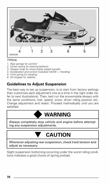
TYPICAL
1. Rear springs for comfort2. Center spring for steering behavior3. Stopper strap for snowmobile weight transfer4. Acceleration and control modulator (ACM) — Handling5. Front spring for handling6. Ski stopper for stability
Guidelines to Adjust Suspension
The best way to set up suspension, is to start from factory settingsthen customize each adjustment one at a time in the right order (re-fer to next illustrations). Then, test run the snowmobile always withthe same conditions; trail, speed, snow, driver riding position etc.Change adjustment and retest. Proceed methodically until you aresatisfied.
Slight suspension bottoming occurring under the worst riding condi-tions indicates a good choice of spring preload.
◆ WARNING
Always completely stop vehicle and engine before attempt-ing any suspension adjustments.
- CAUTION
Whenever adjusting rear suspension, check track tension andadjust as necessary.
A03H2AB3 6 5214
mmo9903a.bk : mmo9903b.fm5 Page 70 Monday, June 15, 1998 8:05 AM
71
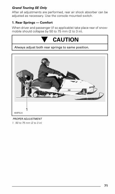
Grand Touring SE Only
After all adjustments are performed, rear air shock absorber can beadjusted as necessary. Use the console mounted switch.
1. Rear Springs — Comfort
When driver and passenger (if so applicable) take place rear of snow-mobile should collapse by 50 to 75 mm (2 to 3 in).
PROPER ADJUSTMENT
1. 50 to 75 mm (2 to 3 in)
- CAUTION
Always adjust both rear springs to same position.
A03F2LA1
mmo9903a.bk : mmo9903b.fm5 Page 71 Monday, June 15, 1998 8:05 AM
72
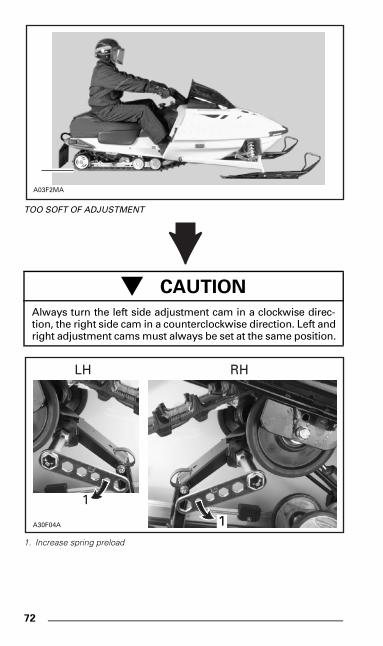
TOO SOFT OF ADJUSTMENT
1. Increase spring preload
- CAUTION
Always turn the left side adjustment cam in a clockwise direc-tion, the right side cam in a counterclockwise direction. Left andright adjustment cams must always be set at the same position.
A03F2MA
1A30F04A
RHLH
1
1
mmo9903a.bk : mmo9903b.fm5 Page 72 Monday, June 15, 1998 8:05 AM
73
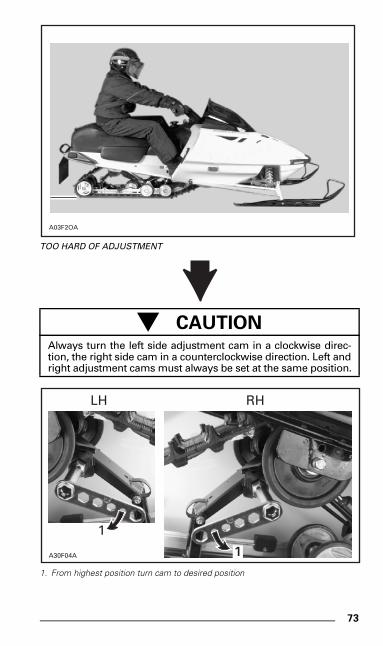
TOO HARD OF ADJUSTMENT
1. From highest position turn cam to desired position
- CAUTIONAlways turn the left side adjustment cam in a clockwise direc-tion, the right side cam in a counterclockwise direction. Left andright adjustment cams must always be set at the same position.
A03F2OA
1A30F04A
RHLH
1
1
mmo9903a.bk : mmo9903b.fm5 Page 73 Monday, June 15, 1998 8:05 AM
74
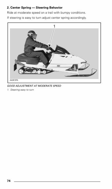
2. Center Spring — Steering Behavior
Ride at moderate speed on a trail with bumpy conditions.
If steering is easy to turn adjust center spring accordingly.
GOOD ADJUSTMENT AT MODERATE SPEED
1. Steering easy to turn
A03F2PA
1
mmo9903a.bk : mmo9903b.fm5 Page 74 Monday, June 15, 1998 8:05 AM
75
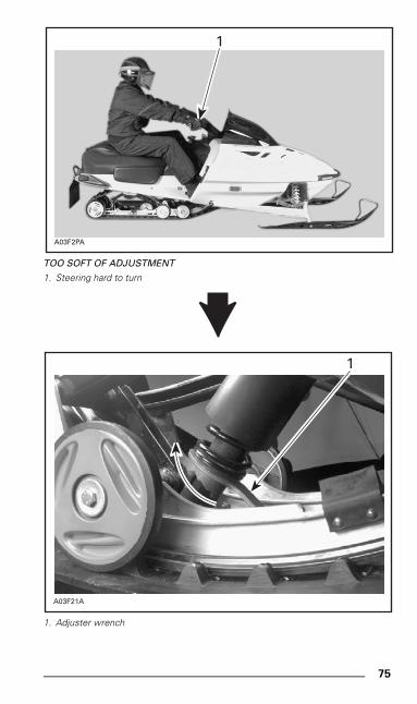
TOO SOFT OF ADJUSTMENT
1. Steering hard to turn
1. Adjuster wrench
A03F2PA
1
A03F21A
1
mmo9903a.bk : mmo9903b.fm5 Page 75 Monday, June 15, 1998 8:05 AM
76
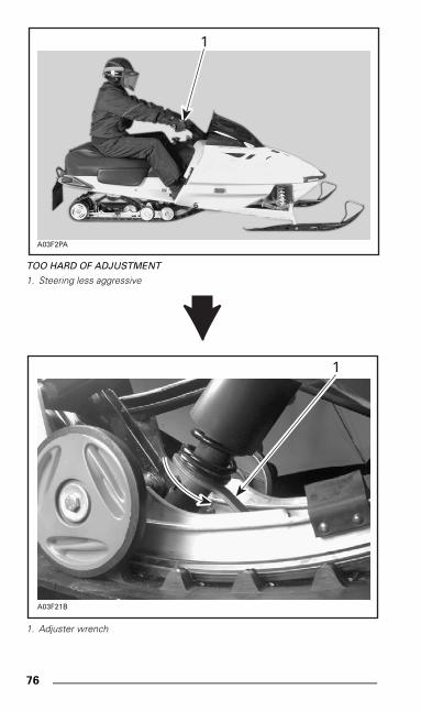
TOO HARD OF ADJUSTMENT
1. Steering less aggressive
1. Adjuster wrench
A03F2PA
1
A03F21B
1
mmo9903a.bk : mmo9903b.fm5 Page 76 Monday, June 15, 1998 8:05 AM
77
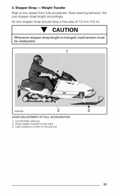
3. Stopper Strap — Weight Transfer
Ride at low speed then fully accelerate. Note steering behavior. Ad-just stopper strap length accordingly.
At rest stopper strap should have a free play of 12 mm (1/2 in).
GOOD ADJUSTMENT AT FULL ACCELERATION
1. Comfortable steering2. Good weight transfer to the track3. Light pressure of skis on the ground
- CAUTION
Whenever stopper strap length is changed, track tension mustbe readjusted.
A03F2OB
1
32
mmo9903a.bk : mmo9903b.fm5 Page 77 Monday, June 15, 1998 8:05 AM
78
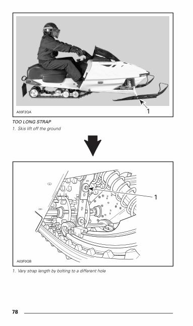
TOO LONG STRAP
1. Skis lift off the ground
1. Vary strap length by bolting to a different hole
A03F2QA 1
A03F0QB
1
mmo9903a.bk : mmo9903b.fm5 Page 78 Monday, June 15, 1998 8:05 AM
79
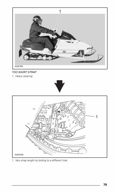
TOO SHORT STRAP
1. Heavy steering
1. Vary strap length by bolting to a different hole
A03F2PA
1
A03F0QB
1
mmo9903a.bk : mmo9903b.fm5 Page 79 Monday, June 15, 1998 8:05 AM
80
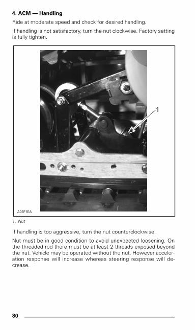
4. ACM — Handling
Ride at moderate speed and check for desired handling.
If handling is not satisfactory, turn the nut clockwise. Factory settingis fully tighten.
1. Nut
If handling is too aggressive, turn the nut counterclockwise.
Nut must be in good condition to avoid unexpected loosening. Onthe threaded rod there must be at least 2 threads exposed beyondthe nut. Vehicle may be operated without the nut. However acceler-ation response will increase whereas steering response will de-crease.
1
A03F1EA
mmo9903a.bk : mmo9903b.fm5 Page 80 Monday, June 15, 1998 8:05 AM
81
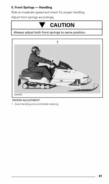
5. Front Springs — Handling
Ride at moderate speed and check for proper handling.
Adjust front springs accordingly.
PROPER ADJUSTMENT
1. Good handling and comfortable steering
- CAUTION
Always adjust both front springs to same position.
A03F2PA
1
mmo9903a.bk : mmo9903b.fm5 Page 81 Monday, June 15, 1998 8:05 AM
82
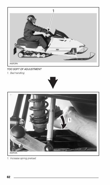
TOO SOFT OF ADJUSTMENT
1. Bad handling
1. Increase spring preload
A03F2PA
1
A03F2IA
1
mmo9903a.bk : mmo9903b.fm5 Page 82 Monday, June 15, 1998 8:05 AM
83
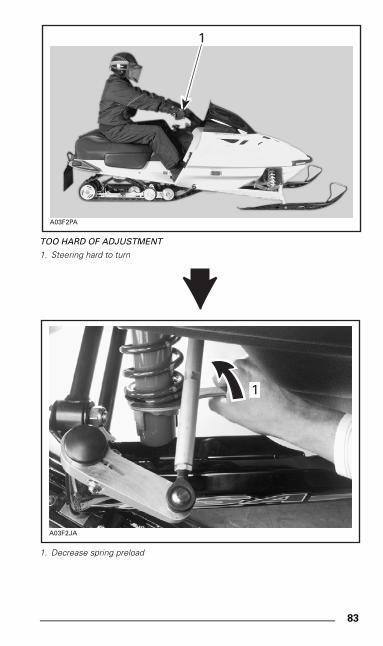
TOO HARD OF ADJUSTMENT
1. Steering hard to turn
1. Decrease spring preload
A03F2PA
1
A03F2JA
1
mmo9903a.bk : mmo9903b.fm5 Page 83 Monday, June 15, 1998 8:05 AM
84
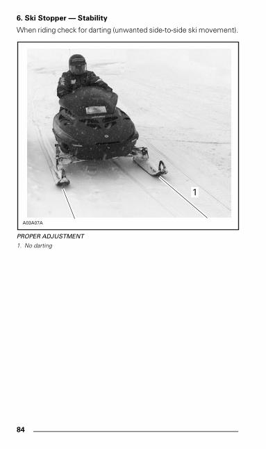
6. Ski Stopper — Stability
When riding check for darting (unwanted side-to-side ski movement).
PROPER ADJUSTMENT
1. No darting
A03A07A
1
mmo9903a.bk : mmo9903b.fm5 Page 84 Monday, June 15, 1998 8:05 AM
85
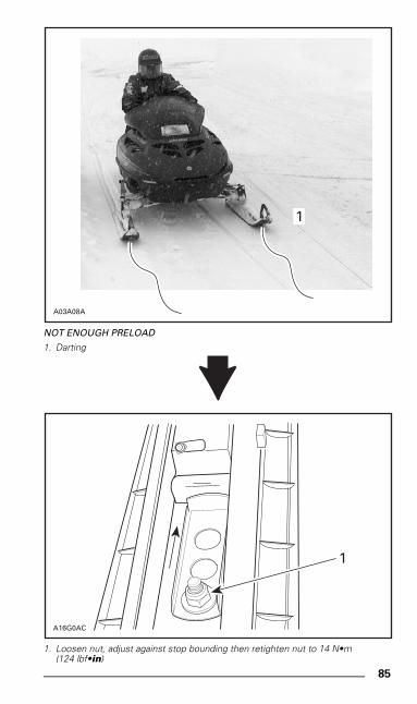
NOT ENOUGH PRELOAD
1. Darting
1. Loosen nut, adjust against stop bounding then retighten nut to 14 N•m (124 lbf•in)
A03A08A
1
A16G0AC
1
mmo9903a.bk : mmo9903b.fm5 Page 85 Monday, June 15, 1998 8:05 AM
86
TROUBLESHOOTING CHART
In Deep Snow
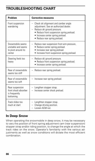
When operating the snowmobile in deep snow, it may be necessaryto vary the position of front spring adjustment cam (rear suspension)stopper strap and/or riding position, to change the angle at which thetrack rides on the snow. Operator’s familiarity with the various ad-justments as well as snow conditions will dictate the most efficientcombination.
Problem Corrective measures
Front suspensionwandering
– Check ski alignment and camber angleadjustment. See an authorized dealer.
– Reduce ski ground pressure.• Reduce front suspension spring preload.• Increase center spring preload.• Reduce rear spring preload.
Snowmobile seems unstable and seems to pivot around its center
– Reduce rear suspension front arm pressure.• Reduce center spring preload.• Increase rear spring preload.• Increase front suspension spring preload.
Steering feels tooheavy
– Reduce ski ground pressure.• Reduce front suspension spring preload.• Increase center spring preload.
Rear of snowmobileseems too stiff
– Reduce rear spring preload.
Rear of snowmobileseems too soft
– Increase rear spring preload.
Rear suspensionfront shock absorberis frequentlybottoming
– Lengthen stopper strap.– Increase center shock preload.
Track slides toomuch at start
– Lengthten stopper strap.– Change driving position.– Loosen ACM nut.
mmo9903a.bk : mmo9903b.fm5 Page 86 Monday, June 15, 1998 8:05 AM
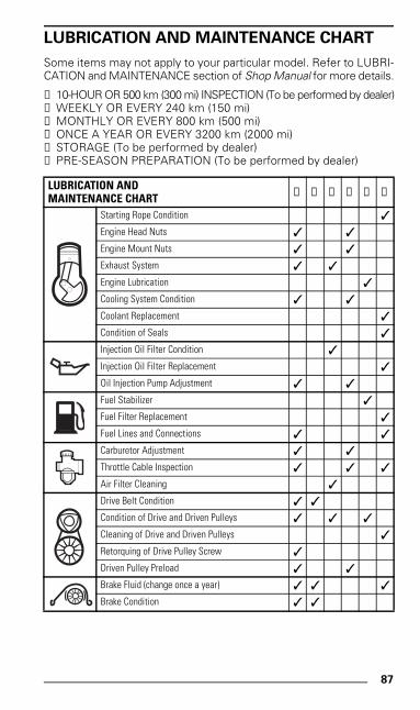
87
LUBRICATION AND MAINTENANCE CHART
Some items may not apply to your particular model. Refer to LUBRI-CATION and MAINTENANCE section of Shop Manual for more details.
➀ 10-HOUR OR 500 km (300 mi) INSPECTION (To be performed by dealer)➁ WEEKLY OR EVERY 240 km (150 mi)➂ MONTHLY OR EVERY 800 km (500 mi)➃ ONCE A YEAR OR EVERY 3200 km (2000 mi)➄ STORAGE (To be performed by dealer) ➅ PRE-SEASON PREPARATION (To be performed by dealer)
LUBRICATION ANDMAINTENANCE CHART ➀ ➁ ➂ ➃ ➄ ➅
Starting Rope Condition ✓
Engine Head Nuts ✓ ✓
Engine Mount Nuts ✓ ✓
Exhaust System ✓ ✓
Engine Lubrication ✓
Cooling System Condition ✓ ✓
Coolant Replacement ✓
Condition of Seals ✓
Injection Oil Filter Condition ✓
Injection Oil Filter Replacement ✓
Oil Injection Pump Adjustment ✓ ✓
Fuel Stabilizer ✓
Fuel Filter Replacement ✓
Fuel Lines and Connections ✓ ✓
Carburetor Adjustment ✓ ✓
Throttle Cable Inspection ✓ ✓ ✓
Air Filter Cleaning ✓
Drive Belt Condition ✓ ✓
Condition of Drive and Driven Pulleys ✓ ✓ ✓
Cleaning of Drive and Driven Pulleys ✓
Retorquing of Drive Pulley Screw ✓
Driven Pulley Preload ✓ ✓
Brake Fluid (change once a year) ✓ ✓ ✓
Brake Condition ✓ ✓
mmo9903a.bk : mmo9903b.fm5 Page 87 Monday, June 15, 1998 8:05 AM
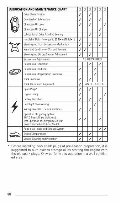
88
* Before installing new spark plugs at pre-season preparation, it issuggested to burn excess storage oil by starting the engine withthe old spark plugs. Only perform this operation in a well ventilat-ed area.
LUBRICATION AND MAINTENANCE CHART ➀ ➁ ➂ ➃ ➄ ➅
Drive Chain Tension ✓ ✓
Countershaft Lubrication ✓ ✓ ✓
Chaincase Oil Level ✓ ✓ ✓
Chaincase Oil Change ✓
Lubrication of Drive Axle End Bearing ✓ ✓
Handlebar Bolts, Retorque to 26 N•m (19 lbf•ft) ✓
Steering and Front Suspension Mechanism ✓ ✓ ✓
Wear and Condition of Skis and Runners ✓ ✓
Steering and Ski Leg Camber Adjustment ✓ ✓
Suspension Adjustments AS REQUIRED
Suspension Lubrication ✓ ✓
Suspension Condition ✓ ✓
Suspension Stopper Strap Condition ✓
Track Condition ✓ ✓
Track Tension and Alignment ✓ AS REQUIRED
Spark Plugs* ✓ ✓
Engine Timing ✓ ✓
Battery Condition ✓ ✓ ✓
Headlight Beam Aiming ✓
Wiring Harnesses, Cables and Lines ✓ ✓
Operation of Lighting System(HI/LO Beam, Brake Light, etc.),Test Operation of Emergency Cut-OutSwitch and Tether Cut-Out Switch
✓ ✓ ✓
Rags in Air Intake and Exhaust System ✓ ✓
Engine Compartment ✓ ✓
Vehicle Cleaning and Protection ✓ ✓ ✓
mmo9903a.bk : mmo9903b.fm5 Page 88 Monday, June 15, 1998 8:05 AM
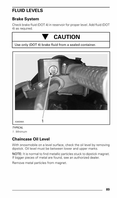
89
FLUID LEVELS
Brake System
Check brake fluid (DOT 4) in reservoir for proper level. Add fluid (DOT4) as required.
TYPICAL
1. Minimum
Chaincase Oil Level
With snowmobile on a level surface, check the oil level by removingdipstick. Oil level must be between lower and upper marks.
NOTE: It is normal to find metallic particles stuck to dipstick magnet.If bigger pieces of metal are found, see an authorized dealer.
Remove metal particles from magnet.
- CAUTION
Use only (DOT 4) brake fluid from a sealed container.
A30D08A 1
mmo9903a.bk : mmo9903b.fm5 Page 89 Monday, June 15, 1998 8:05 AM
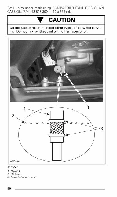
90
Refill up to upper mark using BOMBARDIER SYNTHETIC CHAIN-CASE OIL (P/N 413 803 300 — 12 x 355 mL).
TYPICAL
1. Dipstick2. Oil level3. Level between marks
- CAUTION
Do not use unrecommended other types of oil when servic-ing. Do not mix synthetic oil with other types of oil.
A30D0AA
1
3
1
2
mmo9903a.bk : mmo9903b.fm5 Page 90 Monday, June 15, 1998 8:05 AM
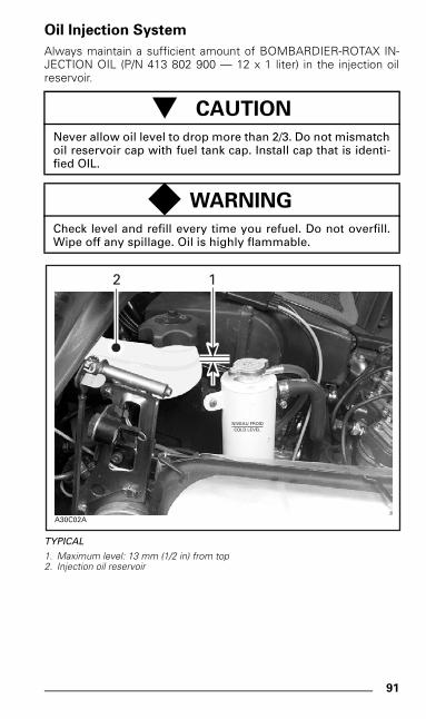
91
Oil Injection System
Always maintain a sufficient amount of BOMBARDIER-ROTAX IN-JECTION OIL (P/N 413 802 900 — 12 x 1 liter) in the injection oilreservoir.
TYPICAL
1. Maximum level: 13 mm (1/2 in) from top2. Injection oil reservoir
- CAUTION
Never allow oil level to drop more than 2/3. Do not mismatchoil reservoir cap with fuel tank cap. Install cap that is identi-fied OIL.
◆ WARNING
Check level and refill every time you refuel. Do not overfill.Wipe off any spillage. Oil is highly flammable.
2
A30C02A
1
NIVEAU FROIDCOLD LEVEL
mmo9903a.bk : mmo9903b.fm5 Page 91 Monday, June 15, 1998 8:05 AM
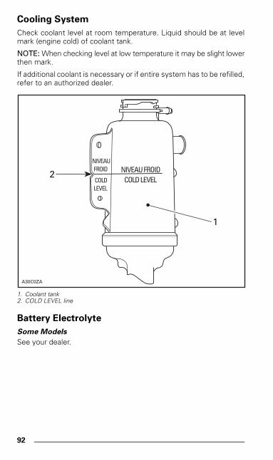
92
Cooling System
Check coolant level at room temperature. Liquid should be at levelmark (engine cold) of coolant tank.
NOTE: When checking level at low temperature it may be slight lowerthen mark.
If additional coolant is necessary or if entire system has to be refilled,refer to an authorized dealer.
1. Coolant tank2. COLD LEVEL line
Battery Electrolyte
Some Models
See your dealer.
NIVEAU FROIDCOLD LEVEL
NIVEAUFROID
COLDLEVEL
A30C0ZA
1
2
mmo9903a.bk : mmo9903b.fm5 Page 92 Monday, June 15, 1998 8:05 AM
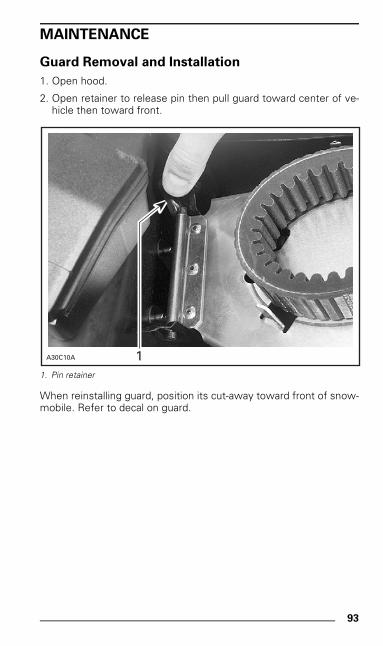
93
MAINTENANCE
Guard Removal and Installation
1. Open hood.
2. Open retainer to release pin then pull guard toward center of ve-hicle then toward front.
1. Pin retainer
When reinstalling guard, position its cut-away toward front of snow-mobile. Refer to decal on guard.
1A30C10A
mmo9903a.bk : mmo9903b.fm5 Page 93 Monday, June 15, 1998 8:05 AM
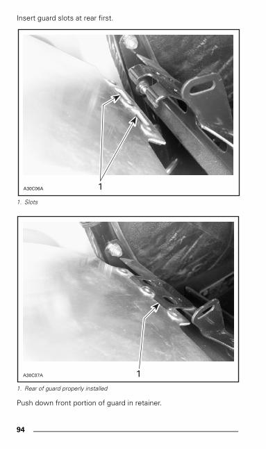
94
Insert guard slots at rear first.
1. Slots
1. Rear of guard properly installed
Push down front portion of guard in retainer.
A30C06A 1
A30C07A 1
mmo9903a.bk : mmo9903b.fm5 Page 94 Monday, June 15, 1998 8:05 AM
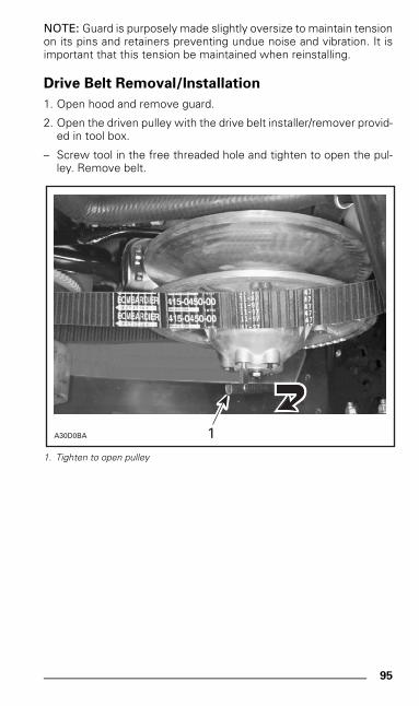
95
NOTE: Guard is purposely made slightly oversize to maintain tensionon its pins and retainers preventing undue noise and vibration. It isimportant that this tension be maintained when reinstalling.
Drive Belt Removal/Installation
1. Open hood and remove guard.
2. Open the driven pulley with the drive belt installer/remover provid-ed in tool box.
– Screw tool in the free threaded hole and tighten to open the pul-ley. Remove belt.
1. Tighten to open pulley
A30D0BA 1
mmo9903a.bk : mmo9903b.fm5 Page 95 Monday, June 15, 1998 8:05 AM
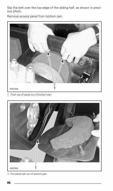
96
Slip the belt over the top edge of the sliding half, as shown in previ-ous photo.
Remove access panel from bottom pan.
1. Push top of panel out of bottom pan
1. Pull panel tab out of bottom pan
A30C04A 1
A30C05A 1
mmo9903a.bk : mmo9903b.fm5 Page 96 Monday, June 15, 1998 8:05 AM
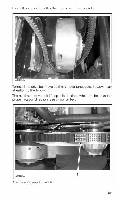
97
Slip belt under drive pulley then, remove it from vehicle.
To install the drive belt, reverse the removal procedure, however payattention to the following:
The maximum drive belt life span is obtained when the belt has theproper rotation direction. See arrow on belt.
1. Arrow pointing front of vehicle
A30D0CA
A30D0DA 1
mmo9903a.bk : mmo9903b.fm5 Page 97 Monday, June 15, 1998 8:05 AM
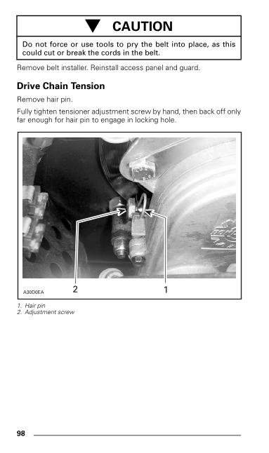
98
Remove belt installer. Reinstall access panel and guard.
Drive Chain Tension
Remove hair pin.
Fully tighten tensioner adjustment screw by hand, then back off onlyfar enough for hair pin to engage in locking hole.
1. Hair pin2. Adjustment screw
- CAUTION
Do not force or use tools to pry the belt into place, as thiscould cut or break the cords in the belt.
A30D0EA 12
mmo9903a.bk : mmo9903b.fm5 Page 98 Monday, June 15, 1998 8:05 AM
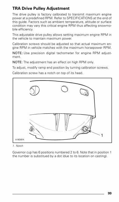
99
TRA Drive Pulley Adjustment
The drive pulley is factory calibrated to transmit maximum enginepower at a predefined RPM. Refer to SPECIFICATIONS at the end ofthis guide. Factors such as ambient temperature, altitude or surfacecondition may vary this critical engine RPM thus affecting snowmo-bile efficiency.
This adjustable drive pulley allows setting maximum engine RPM inthe vehicle to maintain maximum power.
Calibration screws should be adjusted so that actual maximum en-gine RPM in vehicle matches with the maximum horsepower RPM.
NOTE: Use precision digital tachometer for engine RPM adjust-ment.
NOTE: The adjustment has an effect on high RPM only.
To adjust, modify ramp end position by turning calibration screws.
Calibration screw has a notch on top of its head.
1. Notch
Governor cup has 6 positions numbered 2 to 6. Note that in position 1the number is substitued by a dot (due to its location on casting).
A16D0FA
1
mmo9903a.bk : mmo9903b.fm5 Page 99 Monday, June 15, 1998 8:05 AM
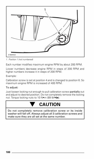
100
1. Position 1 (not numbered)
Each number modifies maximum engine RPM by about 200 RPM.
Lower numbers decrease engine RPM in steps of 200 RPM andhigher numbers increase it in steps of 200 RPM.
Example:
Calibration screw is set at position 4 and is changed to position 6. Somaximum engine RPM is increased of 400 RPM.
To adjust:
Just loosen locking nut enough to pull calibration screw partially outand adjust to desired position. Do not completely remove the lockingnut. Torque locking nuts to 10 N•m (89 lbf•in).
- CAUTION
Do not completely remove calibration screw or its insidewasher will fall off. Always adjust all 3 calibration screws andmake sure they are all set at the same number.
A16D0GA
1
mmo9903a.bk : mmo9903b.fm5 Page 100 Monday, June 15, 1998 8:05 AM
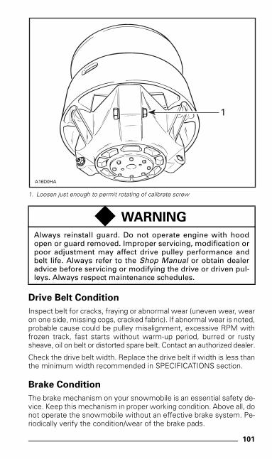
101
1. Loosen just enough to permit rotating of calibrate screw
Drive Belt Condition
Inspect belt for cracks, fraying or abnormal wear (uneven wear, wearon one side, missing cogs, cracked fabric). If abnormal wear is noted,probable cause could be pulley misalignment, excessive RPM withfrozen track, fast starts without warm-up period, burred or rustysheave, oil on belt or distorted spare belt. Contact an authorized dealer.
Check the drive belt width. Replace the drive belt if width is less thanthe minimum width recommended in SPECIFICATIONS section.
Brake Condition
The brake mechanism on your snowmobile is an essential safety de-vice. Keep this mechanism in proper working condition. Above all, donot operate the snowmobile without an effective brake system. Pe-riodically verify the condition/wear of the brake pads.
◆ WARNING
Always reinstall guard. Do not operate engine with hoodopen or guard removed. Improper servicing, modification orpoor adjustment may affect drive pulley performance andbelt life. Always refer to the Shop Manual or obtain dealeradvice before servicing or modifying the drive or driven pul-leys. Always respect maintenance schedules.
A16D0HA
1
mmo9903a.bk : mmo9903b.fm5 Page 101 Monday, June 15, 1998 8:05 AM
102
Brake Adjustment
No adjustment is provided for hydraulic brake. See an authorizeddealer if any problems.
Rear Suspension Condition
Visually inspect all suspension components including slider shoes,springs, wheels, etc.
NOTE: During normal driving, snow will act as a lubricant and cool-ant for the slider shoes. Extensive riding on ice or sanded snow, willcreate excessive heat build-up and cause premature slider shoewear.
Suspension Stopper Strap Condition
Inspect stopper strap for wear and cracks, bolt and nut for tightness.If loose inspect holes for deformation. Replace as required. Torquenut to 9 N•m (80 lbf•in).
Track Condition
Lift the rear of the snowmobile and support it off the ground. Withthe engine off, rotate the track by hand, and inspect condition. Ifworn or cut, or if track fibers are exposed, or if missing or defectiveinserts or guides are noted; contact an authorized dealer.
◆ WARNING
Do not operate or rotate a track if torn, damaged or excessive-ly worn.
mmo9903a.bk : mmo9903b.fm5 Page 102 Monday, June 15, 1998 8:05 AM
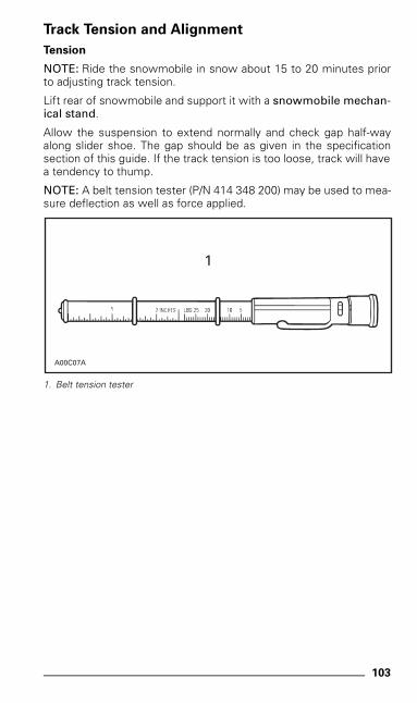
103
Track Tension and Alignment
Tension
NOTE: Ride the snowmobile in snow about 15 to 20 minutes priorto adjusting track tension.
Lift rear of snowmobile and support it with a snowmobile mechan-ical stand.
Allow the suspension to extend normally and check gap half-wayalong slider shoe. The gap should be as given in the specificationsection of this guide. If the track tension is too loose, track will havea tendency to thump.
NOTE: A belt tension tester (P/N 414 348 200) may be used to mea-sure deflection as well as force applied.
1. Belt tension tester
A00C07A
1
mmo9903a.bk : mmo9903b.fm5 Page 103 Monday, June 15, 1998 8:05 AM
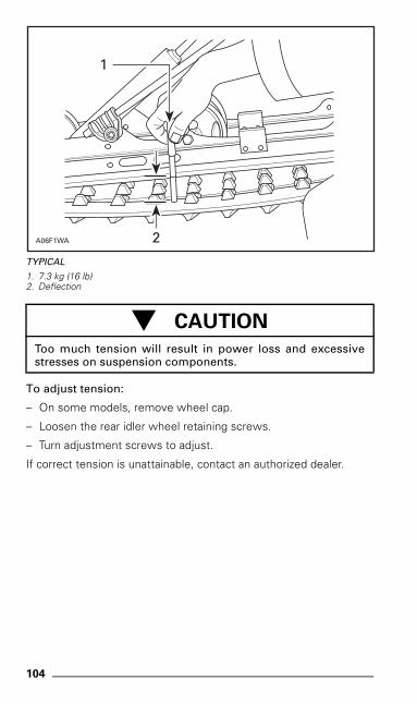
104
TYPICAL
1. 7.3 kg (16 lb)2. Deflection
To adjust tension:
– On some models, remove wheel cap.
– Loosen the rear idler wheel retaining screws.
– Turn adjustment screws to adjust.
If correct tension is unattainable, contact an authorized dealer.
- CAUTION
Too much tension will result in power loss and excessivestresses on suspension components.
1
2A06F1WA
mmo9903a.bk : mmo9903b.fm5 Page 104 Monday, June 15, 1998 8:05 AM
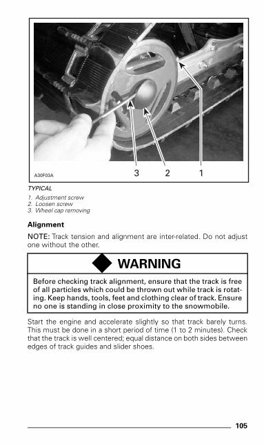
105
TYPICAL
1. Adjustment screw2. Loosen screw3. Wheel cap removing
Alignment
NOTE: Track tension and alignment are inter-related. Do not adjustone without the other.
Start the engine and accelerate slightly so that track barely turns.This must be done in a short period of time (1 to 2 minutes). Checkthat the track is well centered; equal distance on both sides betweenedges of track guides and slider shoes.
◆ WARNING
Before checking track alignment, ensure that the track is freeof all particles which could be thrown out while track is rotat-ing. Keep hands, tools, feet and clothing clear of track. Ensureno one is standing in close proximity to the snowmobile.
A30F03A 123
mmo9903a.bk : mmo9903b.fm5 Page 105 Monday, June 15, 1998 8:05 AM
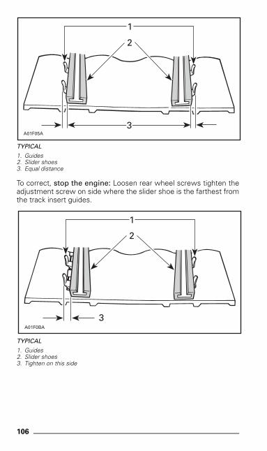
106
TYPICAL
1. Guides2. Slider shoes3. Equal distance
To correct, stop the engine: Loosen rear wheel screws tighten theadjustment screw on side where the slider shoe is the farthest fromthe track insert guides.
TYPICAL
1. Guides2. Slider shoes3. Tighten on this side
A01F05A
1
2
3
A01F0BA
1
2
3
mmo9903a.bk : mmo9903b.fm5 Page 106 Monday, June 15, 1998 8:05 AM
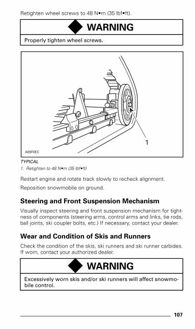
107
Retighten wheel screws to 48 N•m (35 lbf•ft).
TYPICAL
1. Retighten to 48 N•m (35 lbf•ft)
Restart engine and rotate track slowly to recheck alignment.
Reposition snowmobile on ground.
Steering and Front Suspension Mechanism
Visually inspect steering and front suspension mechanism for tight-ness of components (steering arms, control arms and links, tie rods,ball joints, ski coupler bolts, etc.) If necessary, contact your dealer.
Wear and Condition of Skis and Runners
Check the condition of the skis, ski runners and ski runner carbides.If worn, contact your authorized dealer.
◆ WARNING
Properly tighten wheel screws.
◆ WARNING
Excessively worn skis and/or ski runners will affect snowmo-bile control.
1A05F0EC
mmo9903a.bk : mmo9903b.fm5 Page 107 Monday, June 15, 1998 8:05 AM
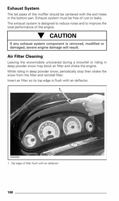
108
Exhaust System
The tail pipes of the muffler should be centered with the exit holesin the bottom pan. Exhaust system must be free of rust or leaks.
The exhaust system is designed to reduce noise and to improve thetotal performance of the engine.
Air Filter Cleaning
Leaving the snowmobile uncovered during a snowfall or riding indeep powder snow may block air filter and choke the engine.
While riding in deep powder snow, periodically stop then shake thesnow from the filter and reinstall filter.
Insert air filter so its top edge is flush with air deflector.
1. Top edge of filter flush with air deflector
- CAUTION
If any exhaust system component is removed, modified ordamaged, severe engine damage will result.
A30H0RA
1
mmo9903a.bk : mmo9903b.fm5 Page 108 Monday, June 15, 1998 8:05 AM
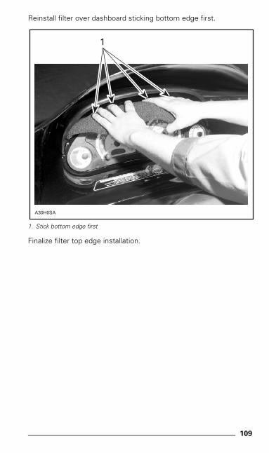
109
Reinstall filter over dashboard sticking bottom edge first.
1. Stick bottom edge first
Finalize filter top edge installation.
A30H0SA
1
mmo9903a.bk : mmo9903b.fm5 Page 109 Monday, June 15, 1998 8:05 AM
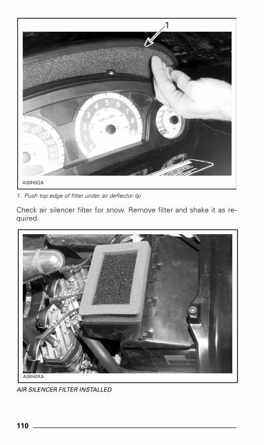
110
1. Push top edge of filter under air deflector lip
Check air silencer filter for snow. Remove filter and shake it as re-quired.
AIR SILENCER FILTER INSTALLED
A30H0QA
1
A30H0XA
mmo9903a.bk : mmo9903b.fm5 Page 110 Monday, June 15, 1998 8:05 AM
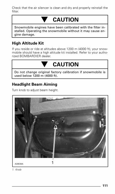
111
Check that the air silencer is clean and dry and properly reinstall thefilter.
High Altitude Kit
If you reside or ride at altitudes above 1200 m (4000 ft), your snow-mobile should have a high altitude kit installed. Refer to your autho-rized BOMBARDIER dealer.
Headlight Beam Aiming
Turn knob to adjust beam height.
1. Knob
- CAUTION
Snowmobile engines have been calibrated with the filter in-stalled. Operating the snowmobile without it may cause en-gine damage.
- CAUTION
Do not change original factory calibration if snowmobile isused below 1200 m (4000 ft).
A30E08A 1
mmo9903a.bk : mmo9903b.fm5 Page 111 Monday, June 15, 1998 8:05 AM
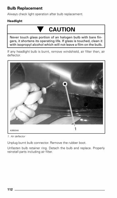
112
Bulb Replacement
Always check light operation after bulb replacement.
Headlight
If any headlight bulb is burnt, remove windshield, air filter then, airdeflector.
1. Air deflector
Unplug burnt bulb connector. Remove the rubber boot.
Unfasten bulb retainer ring. Detach the bulb and replace. Properlyreinstall parts including air filter.
- CAUTION
Never touch glass portion of an halogen bulb with bare fin-gers, it shortens its operating life. If glass is touched, clean itwith isopropyl alcohol which will not leave a film on the bulb.
A30E04A 1
mmo9903a.bk : mmo9903b.fm5 Page 112 Monday, June 15, 1998 8:05 AM
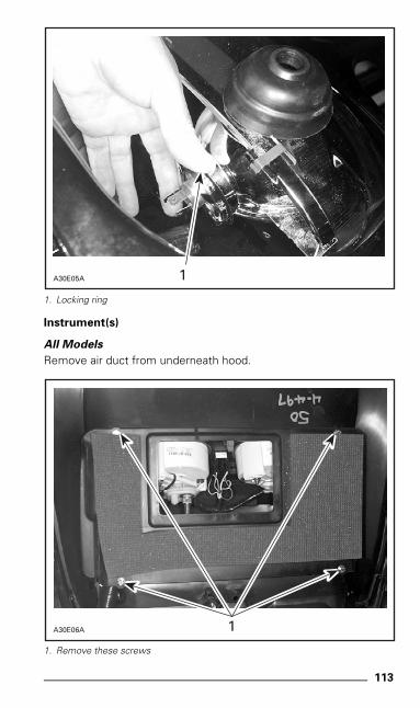
113
1. Locking ring
Instrument(s)
All Models
Remove air duct from underneath hood.
1. Remove these screws
A30E05A 1
A30E06A 1
mmo9903a.bk : mmo9903b.fm5 Page 113 Monday, June 15, 1998 8:05 AM
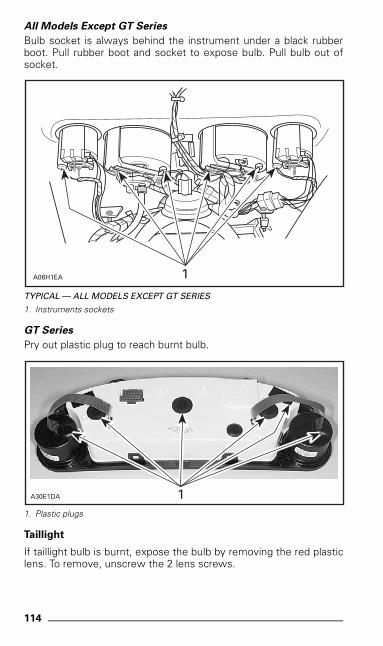
114
All Models Except GT Series
Bulb socket is always behind the instrument under a black rubberboot. Pull rubber boot and socket to expose bulb. Pull bulb out ofsocket.
TYPICAL — ALL MODELS EXCEPT GT SERIES
1. Instruments sockets
GT Series
Pry out plastic plug to reach burnt bulb.
1. Plastic plugs
Taillight
If taillight bulb is burnt, expose the bulb by removing the red plasticlens. To remove, unscrew the 2 lens screws.
1A06H1EA
1A30E1DA
mmo9903a.bk : mmo9903b.fm5 Page 114 Monday, June 15, 1998 8:05 AM
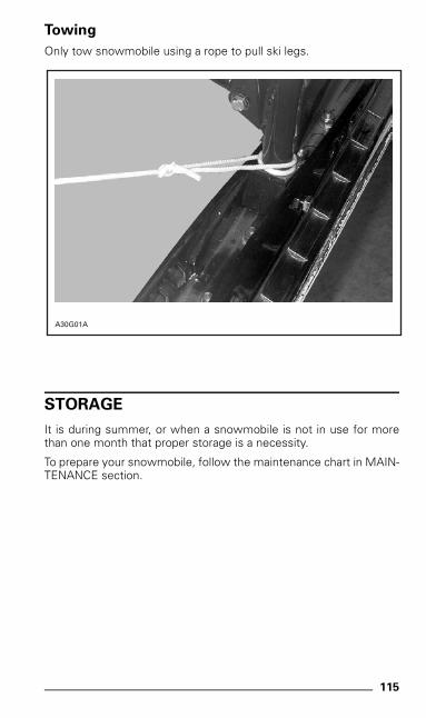
115
Towing
Only tow snowmobile using a rope to pull ski legs.
STORAGE
It is during summer, or when a snowmobile is not in use for morethan one month that proper storage is a necessity.
To prepare your snowmobile, follow the maintenance chart in MAIN-TENANCE section.
A30G01A
mmo9903a.bk : mmo9903b.fm5 Page 115 Monday, June 15, 1998 8:05 AM
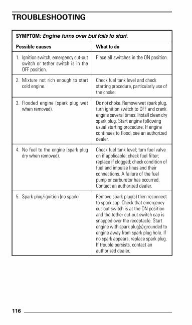
116
TROUBLESHOOTING
SYMPTOM: Engine turns over but fails to start.
Possible causes What to do
1. Ignition switch, emergency cut-outswitch or tether switch is in theOFF position.
Place all switches in the ON position.
2. Mixture not rich enough to startcold engine.
Check fuel tank level and check starting procedure, particularly use of the choke.
3. Flooded engine (spark plug wetwhen removed).
Do not choke. Remove wet spark plug, turn ignition switch to OFF and crank engine several times. Install clean dry spark plug. Start engine following usual starting procedure. If engine continues to flood, see an authorized dealer.
4. No fuel to the engine (spark plugdry when removed).
Check fuel tank level; turn fuel valve on if applicable; check fuel filter; replace if clogged; check condition of fuel and impulse lines and their connections. A failure of the fuel pump or carburetor has occurred. Contact an authorized dealer.
5. Spark plug/ignition (no spark). Remove spark plug(s) then reconnect to spark cap. Check that emergency cut-out switch is at the ON position and the tether cut-out switch cap is snapped over the receptacle. Start engine with spark plug(s) grounded to engine away from spark plug hole. If no spark appears, replace spark plug. If trouble persists, contact an authorized dealer.
mmo9903a.bk : mmo9903b.fm5 Page 116 Monday, June 15, 1998 8:05 AM
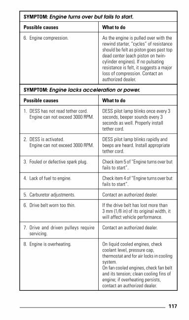
117
SYMPTOM: Engine turns over but fails to start.
Possible causes What to do
6. Engine compression. As the engine is pulled over with the rewind starter, “cycles” of resistance should be felt as piston goes past top dead center (each piston on twin-cylinder engines). If no pulsatingresistance is felt, it suggests a major loss of compression. Contact anauthorized dealer.
SYMPTOM: Engine lacks acceleration or power.
Possible causes What to do
1. DESS has not read tether cord.Engine can not exceed 3000 RPM.
DESS pilot lamp blinks once every 3 seconds, beeper sounds every 3 seconds as well. Properly install tether cord.
2. DESS is activated.Engine can not exceed 3000 RPM.
DESS pilot lamp blinks rapidly and beeps are heard. Install appropriate tether cord.
3. Fouled or defective spark plug. Check item 5 of “Engine turns over but fails to start”.
4. Lack of fuel to engine. Check item 4 of “Engine turns over but fails to start”.
5. Carburetor adjustments. Contact an authorized dealer.
6. Drive belt worn too thin. If the drive belt has lost more than 3 mm (1/8 in) of its original width, it will affect vehicle performance.
7. Drive and driven pulleys requireservicing.
Contact an authorized dealer.
8. Engine is overheating. On liquid cooled engines, checkcoolant level, pressure cap,thermostat and for air locks in cooling system.On fan cooled engines, check fan belt and its tension; clean cooling fins of engine; if overheating persists,contact an authorized dealer.
mmo9903a.bk : mmo9903b.fm5 Page 117 Monday, June 15, 1998 8:05 AM
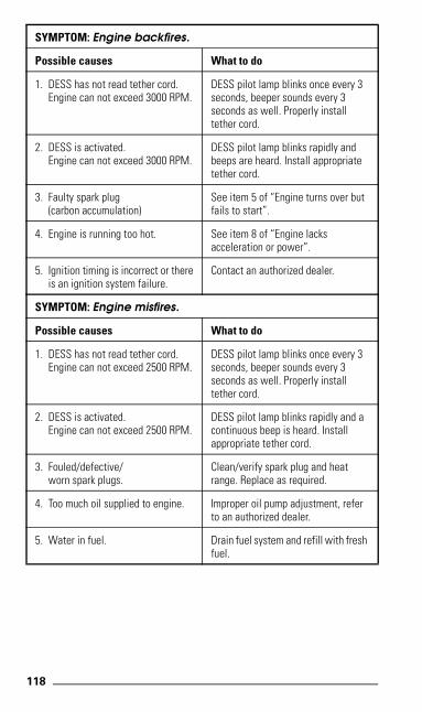
118
SYMPTOM: Engine backfires.
Possible causes What to do
1. DESS has not read tether cord.Engine can not exceed 3000 RPM.
DESS pilot lamp blinks once every 3 seconds, beeper sounds every 3 seconds as well. Properly install tether cord.
2. DESS is activated.Engine can not exceed 3000 RPM.
DESS pilot lamp blinks rapidly and beeps are heard. Install appropriate tether cord.
3. Faulty spark plug(carbon accumulation)
See item 5 of “Engine turns over but fails to start”.
4. Engine is running too hot. See item 8 of “Engine lacksacceleration or power”.
5. Ignition timing is incorrect or thereis an ignition system failure.
Contact an authorized dealer.
SYMPTOM: Engine misfires.
Possible causes What to do
1. DESS has not read tether cord.Engine can not exceed 2500 RPM.
DESS pilot lamp blinks once every 3 seconds, beeper sounds every 3 seconds as well. Properly install tether cord.
2. DESS is activated.Engine can not exceed 2500 RPM.
DESS pilot lamp blinks rapidly and a continuous beep is heard. Install appropriate tether cord.
3. Fouled/defective/worn spark plugs.
Clean/verify spark plug and heat range. Replace as required.
4. Too much oil supplied to engine. Improper oil pump adjustment, referto an authorized dealer.
5. Water in fuel. Drain fuel system and refill with fresh fuel.
mmo9903a.bk : mmo9903b.fm5 Page 118 Monday, June 15, 1998 8:05 AM
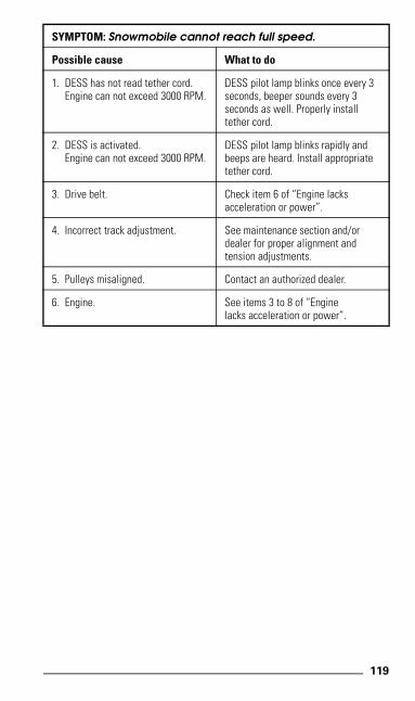
119
SYMPTOM: Snowmobile cannot reach full speed.
Possible cause What to do
1. DESS has not read tether cord.Engine can not exceed 3000 RPM.
DESS pilot lamp blinks once every 3 seconds, beeper sounds every 3 seconds as well. Properly install tether cord.
2. DESS is activated.Engine can not exceed 3000 RPM.
DESS pilot lamp blinks rapidly and beeps are heard. Install appropriate tether cord.
3. Drive belt. Check item 6 of “Engine lacksacceleration or power”.
4. Incorrect track adjustment. See maintenance section and/or dealer for proper alignment andtension adjustments.
5. Pulleys misaligned. Contact an authorized dealer.
6. Engine. See items 3 to 8 of “Enginelacks acceleration or power”.
mmo9903a.bk : mmo9903b.fm5 Page 119 Monday, June 15, 1998 8:05 AM
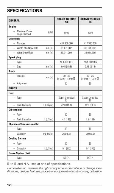
120
SPECIFICATIONS
➀ to ➅ and N.A.: see at end of specifications.Bombardier Inc. reserves the right at any time to discontinue or change spec-ifications, designs features, models or equipment without incurring obligation.
GENERAL GRAND TOURING 700
GRAND TOURING SE
Engine
– Maximum PowerEngine Speed RPM 8000 8000
Drive belt
– Number 417 300 066 417 300 066
– Width of a New Belt mm (in) 35.1 (1.382) 35.1 (1.382)
– Wear Limit Width mm (in) 33.0 (1.299) 33.0 (1.299)
Spark plug
– Type NGK BR 9 ES NGK BR 9 ES
– Gap mm (in) 0.45 (.018) 0.45 (.018)
Track
– Tension mm (in) 30 - 35(1-3/16 - 1-3/8) ➀
30 - 35(1-3/16 - 1-3/8) ➀
– Alignment ➁ ➁
FLUIDS
Fuel
– Type Super Unleaded➂
Super Unleaded➂
– Tank Capacity L (US gal) 42.0 (11.1) 42.0 (11.1)
Oil (engine)
– Type ➃ ➃
– Tank Capacity L (US oz) 4.1 (139) 4.1 (139)
Chaincase/Transmission Oil
– Type ➄ ➄
– Capacity mL (US oz) 250 (8.5) 250 (8.5)
Cooling System
– Type ➅ ➅
– Capacity L (US oz) 5.1 (172) 5.1 (172)
Brake System Fluid
– Type DOT 4 DOT 4
mmo9903b.fm5 Page 120 Thursday, July 9, 1998 4:11 PM
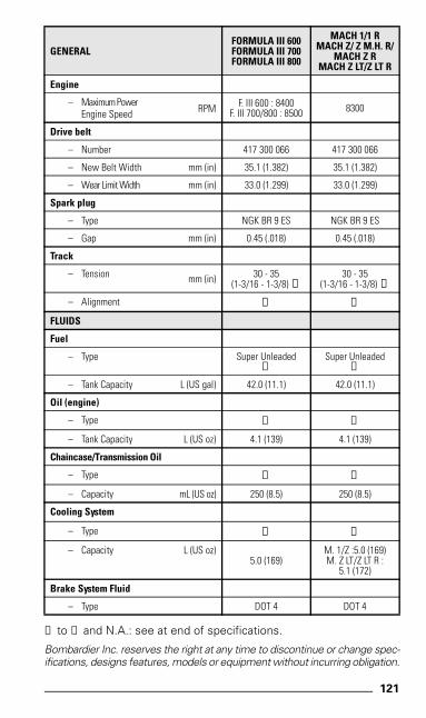
121
➀ to ➅ and N.A.: see at end of specifications.
Bombardier Inc. reserves the right at any time to discontinue or change spec-ifications, designs features, models or equipment without incurring obligation.
GENERALFORMULA III 600 FORMULA III 700FORMULA III 800
MACH 1/1 RMACH Z/ Z M.H. R/
MACH Z RMACH Z LT/Z LT R
Engine
– Maximum PowerEngine Speed RPM F. III 600 : 8400
F. III 700/800 : 8500 8300
Drive belt
– Number 417 300 066 417 300 066
– New Belt Width mm (in) 35.1 (1.382) 35.1 (1.382)
– Wear Limit Width mm (in) 33.0 (1.299) 33.0 (1.299)
Spark plug
– Type NGK BR 9 ES NGK BR 9 ES
– Gap mm (in) 0.45 (.018) 0.45 (.018)
Track
– Tension mm (in) 30 - 35(1-3/16 - 1-3/8) ➀
30 - 35(1-3/16 - 1-3/8) ➀
– Alignment ➁ ➁
FLUIDS
Fuel
– Type Super Unleaded➂
Super Unleaded➂
– Tank Capacity L (US gal) 42.0 (11.1) 42.0 (11.1)
Oil (engine)
– Type ➃ ➃
– Tank Capacity L (US oz) 4.1 (139) 4.1 (139)
Chaincase/Transmission Oil
– Type ➄ ➄
– Capacity mL (US oz) 250 (8.5) 250 (8.5)
Cooling System
– Type ➅ ➅
– Capacity L (US oz)5.0 (169)
M. 1/Z :5.0 (169)M. Z LT/Z LT R :
5.1 (172)
Brake System Fluid
– Type DOT 4 DOT 4
mmo9903b.fm5 Page 121 Thursday, July 9, 1998 4:11 PM

122
➀ Measure gap between slider shoe and bottom inside of trackwhen exerting a downward pull of 7.3 kg (16 lbf) to the track.
➁ Equal distance between edges of track guides and slider shoes.
➂ Super unleaded gasoline with a minimum octane number of 91(R + M)/2.
➃ BOMBARDIER-ROTAX INJECTION OIL (P/N 413 802 900 —12 x 1 L).
➄ BOMBARDIER SYNTHETIC CHAINCASE OIL (P/N 413 803 300 —12 x 355 mL).
➅ Ethylene-glycol antifreeze for aluminum engines mixed with wa-ter (3 parts of antifreeze for 2 parts of water).
N.A.: Not applicable
mmo9903a.bk : mmo9903b.fm5 Page 122 Monday, June 15, 1998 8:05 AM
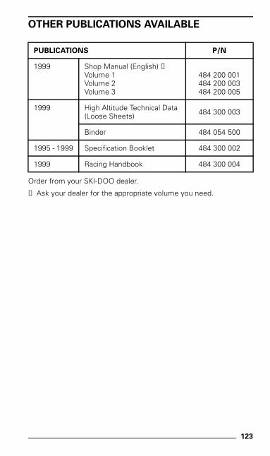
123
OTHER PUBLICATIONS AVAILABLE
Order from your SKI-DOO dealer.
➀ Ask your dealer for the appropriate volume you need.
PUBLICATIONS P/N
1999 Shop Manual (English) ➀Volume 1Volume 2Volume 3
484 200 001484 200 003484 200 005
1999 High Altitude Technical Data(Loose Sheets) 484 300 003
Binder 484 054 500
1995 - 1999 Specification Booklet 484 300 002
1999 Racing Handbook 484 300 004
mmo9903a.bk : mmo9903b.fm5 Page 123 Monday, June 15, 1998 8:05 AM
124
CHANGE OF ADDRESS OR OWNERSHIP
If your address or owner has changed, be sure to fill out and mail thecard provided on next page.
Such notification is likewise necessary for your own safety even af-ter expiration of the original warranty, since Bombardier will be in aposition to contact you if correction to your snowmobile becomesnecessary.
NOTICE TO ALL NEW OWNERS
Make sure to receive the warranty registration card from the previ-ous owner, when the ownership is transferred, as you are entitled tothe unexpired portion of the warranty.
STOLEN UNITS
If the event that your snowmobile is stolen, you should notify yourarea distributor’s warranty department of such.
Please provide your name, address, phone number, vehicle serialnumber and date it was stolen.
Bombardier will provide a list of stolen units to all SKI-DOO dealerson a monthly basis to aid in recovery of such units to their owners.
mmo9903a.bk : mmo9903b.fm5 Page 124 Monday, June 15, 1998 8:05 AM
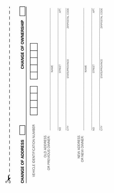
CH
AN
GE
OF A
DD
RE
SS
CH
AN
GE
OF
OW
NE
RS
HIP
VE
HIC
LE ID
EN
TIFI
CAT
ION
NU
MB
ER
OLD
AD
DR
ES
SO
R P
RE
VIO
US
OW
NE
R:
____
____
____
____
____
____
____
____
____
____
____
____
____
____
____
____
____
____
____
_N
AM
E
____
____
____
____
____
____
____
____
____
____
____
____
____
____
____
____
____
____
____
_N
OS
TRE
ET
AP
T.
____
____
____
____
____
____
____
____
____
____
____
____
____
____
____
____
____
____
____
_C
ITY
STA
TE/P
RO
VIN
CE
ZIP
/PO
STA
L C
OD
E
NE
W A
DD
RE
SS
OR
NE
W O
WN
ER
:__
____
____
____
____
____
____
____
____
____
____
____
____
____
____
____
____
____
____
___
NA
ME
____
____
____
____
____
____
____
____
____
____
____
____
____
____
____
____
____
____
____
_N
OS
TRE
ET
AP
T.
____
____
____
____
____
____
____
____
____
____
____
____
____
____
____
____
____
____
____
_C
ITY
STA
TE/P
RO
VIN
CE
ZIP
/PO
STA
L C
OD
E
✁
mmo9903a.bk : mmo9903c.fm5 Page 125 Monday, June 15, 1998 8:05 AM
AFF
IX
BO
MB
AR
DIE
R I
NC
.S
KI-
DO
O W
AR
RA
NT
YV
ALC
OU
RT
(Q
UE
BE
C)
CA
NA
DA
J0E
2L0
PR
OP
ER
PO
STA
GE
mmo9903a.bk : mmo9903c.fm5 Page 126 Monday, June 15, 1998 8:05 AM

NOTE
mmo9903a.bk : mmo9903c.fm5 Page 127 Monday, June 15, 1998 8:05 AM

NOTE
mmo9903a.bk : mmo9903c.fm5 Page 128 Monday, June 15, 1998 8:05 AM