Embed Size (px)
Citation preview
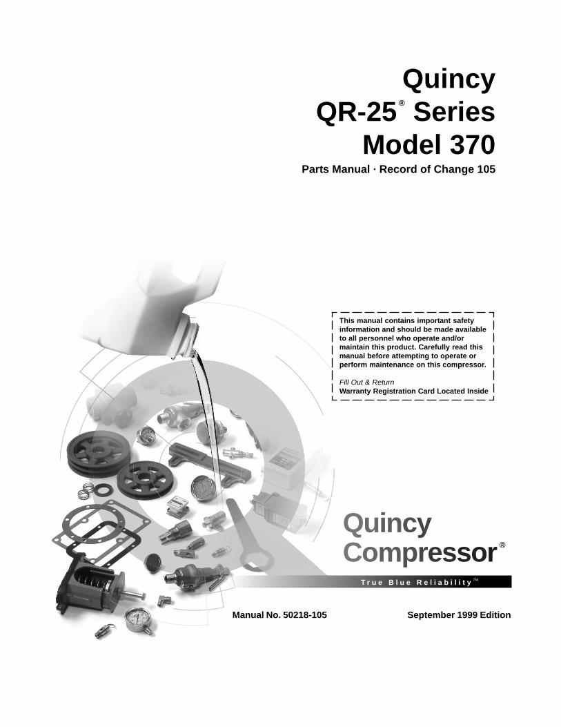
QuincyCompressor®
T r u e B l u e R e l i a b i l i t y TM
This manual contains important safetyinformation and should be made availableto all personnel who operate and/ormaintain this product. Carefully read thismanual before attempting to operate orperform maintenance on this compressor.
Fill Out & ReturnWarranty Registration Card Located Inside
Manual No. 50218-105 September 1999 Edition
QuincyQR-25® Series
Model 370Parts Manual · Record of Change 105
QR 370 Quincy Compressor
50218-105, September 1999 1 3501 Wismann Lane, Quincy IL - 62305-3116
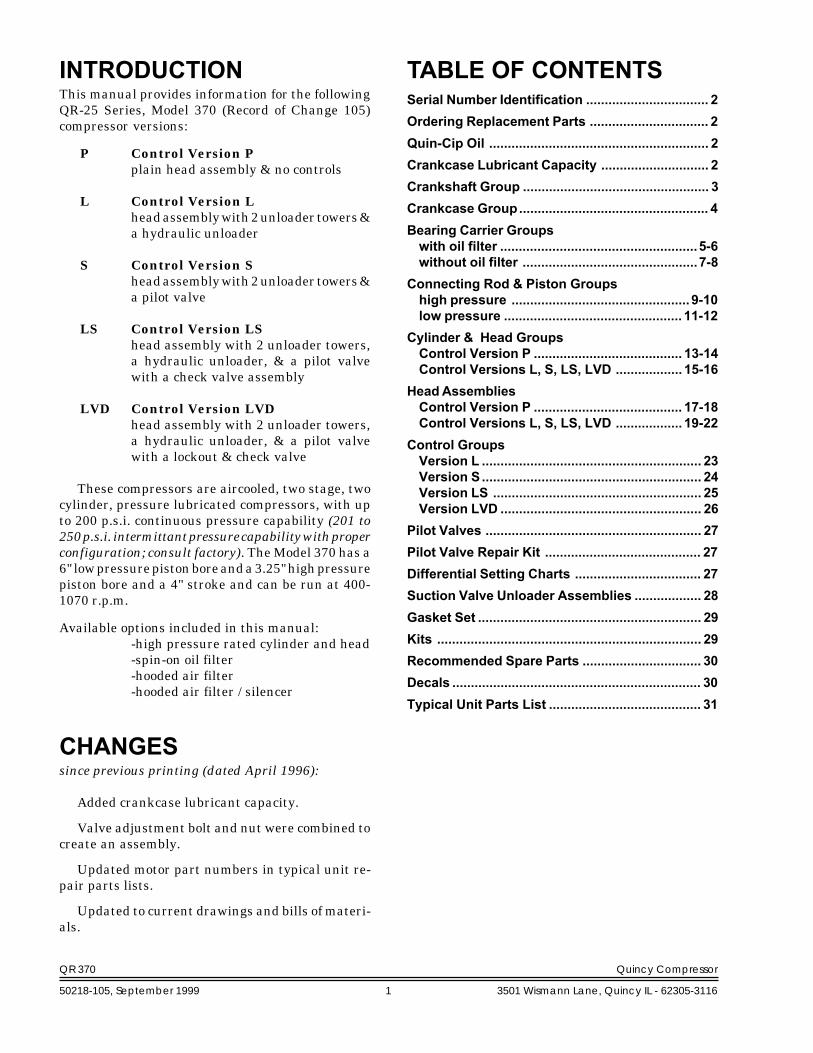
INTRODUCTIONThis manual provides information for the followingQR-25 Series, Model 370 (Record of Change 105)compressor versions:
P Control Version Pplain head assembly & no controls
L Control Version Lhead assembly with 2 unloader towers &a hydraulic unloader
S Control Version Shead assembly with 2 unloader towers &a pilot valve
LS Control Version LShead assembly with 2 unloader towers,a hydraulic unloader, & a pilot valvewith a check valve assembly
LVD Control Version LVDhead assembly with 2 unloader towers,a hydraulic unloader, & a pilot valvewith a lockout & check valve
These compressors are aircooled, two stage, twocylinder, pressure lubricated compressors, with upto 200 p.s.i. continuous pressure capability (201 to250 p.s.i. intermittant pressure capability with properconfiguration; consult factory). The Model 370 has a6" low pressure piston bore and a 3.25" high pressurepiston bore and a 4" stroke and can be run at 400-1070 r.p.m.
Available options included in this manual:-high pressure rated cylinder and head-spin-on oil filter-hooded air filter-hooded air filter / silencer
CHANGESsince previous printing (dated April 1996):
Added crankcase lubricant capacity.
Valve adjustment bolt and nut were combined tocreate an assembly.
Updated motor part numbers in typical unit re-pair parts lists.
Updated to current drawings and bills of materi-als.
TABLE OF CONTENTSSerial Number Identification ................................. 2Ordering Replacement Parts ................................ 2Quin-Cip Oil ........................................................... 2Crankcase Lubricant Capacity ............................. 2Crankshaft Group .................................................. 3Crankcase Group................................................... 4Bearing Carrier Groupswith oil filter .....................................................5-6without oil filter ...............................................7-8
Connecting Rod & Piston Groupshigh pressure ................................................ 9-10low pressure ................................................ 11-12
Cylinder & Head GroupsControl Version P ........................................ 13-14Control Versions L, S, LS, LVD .................. 15-16
HeadAssembliesControl Version P ........................................ 17-18Control Versions L, S, LS, LVD .................. 19-22
Control GroupsVersion L ........................................................... 23Version S........................................................... 24Version LS ........................................................ 25Version LVD ...................................................... 26
Pilot Valves .......................................................... 27Pilot Valve Repair Kit .......................................... 27Differential Setting Charts .................................. 27Suction Valve Unloader Assemblies .................. 28Gasket Set ............................................................ 29Kits ....................................................................... 29Recommended Spare Parts ................................ 30Decals ................................................................... 30Typical Unit Parts List ......................................... 31

QR 370 Quincy Compressor
50218-105, September 1999 2 3501 Wismann Lane, Quincy IL - 62305-3116
MODEL &SERIAL NUMBERIDENTIFICATION Record
ofChange No.
Model & Serial NumberIdentification Tag
The model & serial number tag is located on thehandhole plate side of the crankcase. Fill in thenumbers from your compressor's tag in the corre-sponding spaces provided here and reference thispage when ordering replacement parts.
All replacement parts are to be ordered throughan authorized Quincy Compressor Distributor. In-sist on genuine Quincy parts only! Failure to do somay void warranty.
ORDERINGREPLACEMENT PARTSPrompt service can be rendered on repair parts or-ders if the following information is given:
Item 1) the model number, record of change num-ber, & serial number.
Item 2) the exact part number needed. (Do notorder by item numbers.)
Item 3) the exact quantity needed.Item 4) the preferred type of transportation
CAUTION !DANGER !Follow all safety precautions outlined in the QR-25 Seriesinstruction manual.
WARNING !
QUIN-CIP ® OILRefer to the chart below to order QUIN-CIP compres-sor oil from your local Authorized Quincy Distributor.
Package Part No. Description
Barrel 112541D032 55 gal., SAE 10WPail 112541P032 5 gal., SAE 10W
Gallon 112541G032 1 gal., SAE 10WGallon Case 112541X032 (4)-1 gal., SAE 10W
Quart 112541Q032 1 qt., SAE 10WQuart Case 112541C032 (12)-1 qt., SAE 10W
Barrel 112542D068 55 gal., SAE 20Pail 112542P068 5 gal., SAE 20
Gallon 112542G068 1 gal., SAE 20Gallon Case 112542X068 (4)-1 gal., SAE 20
Quart 112542Q068 1 qt., SAE 20Quart Case 112542C068 (12)-1 qt., SAE 20
Barrel 112543D100 55 gal., SAE 30Pail 112543P100 5 gal., SAE 30
Gallon 112543G100 1 gal., SAE 30Gallon Case 112543X100 (4)-1 gal., SAE 30
Quart 112543Q100 1 qt., SAE 30Quart Case 112543C100 (12)-1 qt., SAE 30
CRANKCASE LUBRICANTCAPACITY
Refer to the Quincy QR-25 Series instruction manual forvital lubrication information.
CAUTION !Do not operate this compressor without a totally enclosedbelt guard or any other required safety equipment.
Airusedforbreathingor foodprocessingmustmeetO.S.H.A.1910.134or F.D.A. 21C.F.R. 178.3570 regulations. Failure todo so may cause severe injury or death.
Model Less Filter With Filter
QR-370 43/4 Qts. add 10 oz.(4.5 lit.) (add 300 ml)
QR 370 Quincy Compressor
50218-105, September 1999 3 3501 Wismann Lane, Quincy IL - 62305-3116
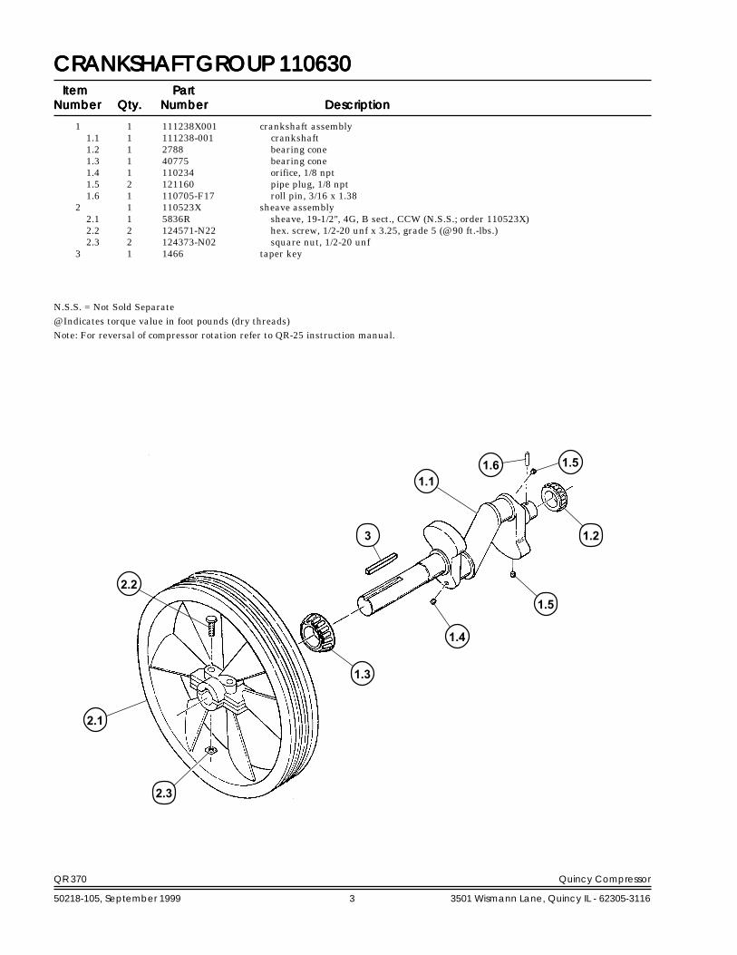
CRANKSHAFT GROUP 110630CRANKSHAFT GROUP 110630CRANKSHAFT GROUP 110630CRANKSHAFT GROUP 110630CRANKSHAFT GROUP 110630ItemItemItemItemItem PartPartPartPartPart
NumberNumberNumberNumberNumber Qty.Qty.Qty.Qty.Qty. NumberNumberNumberNumberNumber DescriptionDescriptionDescriptionDescriptionDescription
1 1 111238X001 crankshaft assembly1.1 1 111238-001 crankshaft1.2 1 2788 bearing cone1.3 1 40775 bearing cone1.4 1 110234 orifice, 1/8 npt1.5 2 121160 pipe plug, 1/8 npt1.6 1 110705-F17 roll pin, 3/16 x 1.38
2 1 110523X sheave assembly2.1 1 5836R sheave, 19-1/2", 4G, B sect., CCW (N.S.S.; order 110523X)2.2 2 124571-N22 hex. screw, 1/2-20 unf x 3.25, grade 5 (@ 90 ft.-lbs.)2.3 2 124373-N02 square nut, 1/2-20 unf
3 1 1466 taper key
2.2
2.1
1.3
3
1.4
1.5
1.2
1.11.6 1.5
2.3
N.S.S. = Not Sold Separate@ Indicates torque value in foot pounds (dry threads)Note: For reversal of compressor rotation refer to QR-25 instruction manual.

QR 370 Quincy Compressor
50218-105, September 1999 4 3501 Wismann Lane, Quincy IL - 62305-3116
CRANKCASE GROUP 110628-004CRANKCASE GROUP 110628-004CRANKCASE GROUP 110628-004CRANKCASE GROUP 110628-004CRANKCASE GROUP 110628-004
ItemItemItemItemItem PartPartPartPartPartNumberNumberNumberNumberNumber Qty.Qty.Qty.Qty.Qty. NumberNumberNumberNumberNumber DescriptionDescriptionDescriptionDescriptionDescription
1 1 6904X crankcase assembly1.1 1 6904R crankcase1.2 1 3720 bearing cup
2 1 2057 square head pipe plug3 * 1383 bearing adjustment shim, .005 steel4 * 1383A bearing adjustment shim, .007 steel5 * 1383B bearing adjustment shim, .020 steel6 * 1383D bearing adjustment shim, .002 steel7 1 6930 adjustment plate (.0015 / .003 crankshaft end play)8 4 123478-L12 hex. screw, 3/8-16 unc x 1.00, grade 59 2 1315 inspection plate gasket10 1 1249-1 inspection plate11 1 6849-1 inspection plate12 12 123478-K12 hex. screw, 5/16-18 unc x 1.00, grade 5 (@ 12 ft.-lbs.)13 1 6726X001 oil gauge assembly
13.1 1 5488-001 oil gauge rod (N.S.S.; order 6726X001)13.2 1 6726 oil gauge knob (N.S.S.; order 6726X001)13.3 2 123157-210 "o"ring, 1/8" wide x 1.00 o.d.
14 1 5783 breather ball15 1 5932 drive pin16 12 110428N031 flatwasher, 5/16
1 6930-1X Replacement Adjustment Plate Assemblyincludes adjustment plate & oil seal
13.3 2 22749-210 "o"ring, 1/8" wide x 1.00 o.d.
13.2
87
65
13.14
31.2
13.3
12
16
11
9
2
12
16
10
91.1
14
15
Maintenance PartsMaintenance PartsMaintenance PartsMaintenance PartsMaintenance Parts
‡
* Quantity as required@ Indicates torque value (dry threads). Tighten multiple bolts, capscrews & hex nuts in a criss-cross or alternating pattern. Bring
each fastener to the recommended torque specification in even increments.N.S.S. = Not Sold Separate‡ For use with diester or phosphate ester synthetic lubricants.
QR 370 Quincy Compressor
50218-105, September 1999 5 3501 Wismann Lane, Quincy IL - 62305-3116
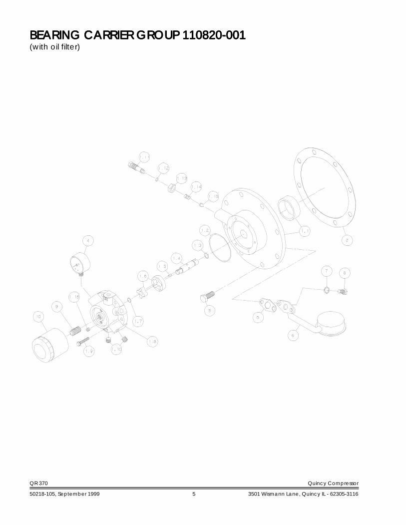
BEARING CARRIER GROUP 110820-001BEARING CARRIER GROUP 110820-001BEARING CARRIER GROUP 110820-001BEARING CARRIER GROUP 110820-001BEARING CARRIER GROUP 110820-001(with oil filter)
QR 370 Quincy Compressor
50218-105, September 1999 6 3501 Wismann Lane, Quincy IL - 62305-3116
ItemItemItemItemItem PartPartPartPartPartNumberNumberNumberNumberNumber Qty.Qty.Qty.Qty.Qty. NumberNumberNumberNumberNumber DescriptionDescriptionDescriptionDescriptionDescription
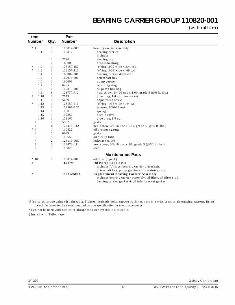
BEARING CARRIER GROUP 110820-001BEARING CARRIER GROUP 110820-001BEARING CARRIER GROUP 110820-001BEARING CARRIER GROUP 110820-001BEARING CARRIER GROUP 110820-001(with oil filter)
1 1 110812-003 bearing carrier assembly1.1 1 110812 bearing carrier
includes:1 2720 bearing cup2 160005 bronze bushing
1.2 1 123157-152 "o"ring, 3/32 wide x 3.44 o.d.1.3 1 123157-112 "o"ring, 3/32 wide x .69 o.d.1.4 1 160002-001 bearing carrier driveshaft1.5 1 160075-001 driveshaft key1.6 1 160003 pump gerotor1.7 1 6285 retaining ring1.8 1 110813-001 oil pump housing1.9 6 123777-J12 hex. screw, 1/4-20 unc x 1.00, grade 5 (@ 6 ft.-lbs.)1.10 2 2719 pipe plug, 1/4 npt, hex socket1.11 1 5489 adjustment screw1.12 1 123157-011 "o"ring, 1/16 wide x .44 o.d.1.13 1 124369-P02 jamnut, 9/16-18 unf1.14 1 1160 spring1.15 1 112857 needle valve1.16 1 121160 pipe plug, 1/8 npt
2 1 5502 gasket3 8 123478-L12 hex. screw, 3/8-16 unc x 1.00, grade 5 (@ 30 ft.-lbs.)4 1 110822 oil pressure gauge5 1 6679 gasket6 1 110659 oil pickup tube7 2 123115-06C lockwasher, 3/88 2 123478-L11 hex. screw, 3/8-16 unc x .88, grade 5 (@ 30 ft.-lbs.)9 1 110825 stud
10 1 110814-001 oil filter (6 pack)160079 Oil Pump Repair Kit
includes "o"rings, bearing carrier driveshaft,driveshaft key, pump gerotor and retaining ring
110812X003 Replacement Bearing Carrier Assemblyincludes bearing carrier assembly, oil filter, oil filter stud,bearing carrier gasket & oil inlet bracket gasket
*
**
*
@ Indicates torque value (dry threads). Tighten multiple bolts, capscrews & hex nuts in a criss-cross or alternating pattern. Bringeach fastener to the recommended torque specification in even increments.
* Can not be used with diester or phosphate ester synthetic lubricants. § Install with Teflon tape.
Maintenance PartsMaintenance PartsMaintenance PartsMaintenance PartsMaintenance Parts**
*
§
§

QR 370 Quincy Compressor
50218-105, September 1999 7 3501 Wismann Lane, Quincy IL - 62305-3116
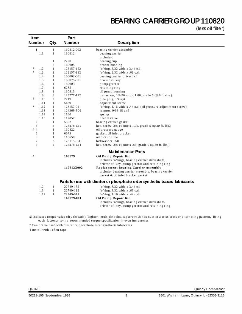
BEARING CARRIER GROUP 110820BEARING CARRIER GROUP 110820BEARING CARRIER GROUP 110820BEARING CARRIER GROUP 110820BEARING CARRIER GROUP 110820(less oil filter)
QR 370 Quincy Compressor
50218-105, September 1999 8 3501 Wismann Lane, Quincy IL - 62305-3116
ItemItemItemItemItem PartPartPartPartPartNumberNumberNumberNumberNumber Qty.Qty.Qty.Qty.Qty. NumberNumberNumberNumberNumber DescriptionDescriptionDescriptionDescriptionDescription
BEARING CARRIER GROUP 110820BEARING CARRIER GROUP 110820BEARING CARRIER GROUP 110820BEARING CARRIER GROUP 110820BEARING CARRIER GROUP 110820(less oil filter)
1 1 110812-002 bearing carrier assembly1.1 1 110812 bearing carrier
includes:1 2720 bearing cup2 160005 bronze bushing
1.2 1 123157-152 "o"ring, 3/32 wide x 3.44 o.d.1.3 1 123157-112 "o"ring, 3/32 wide x .69 o.d.1.4 1 160002-001 bearing carrier driveshaft1.5 1 160075-001 driveshaft key1.6 1 160003 pump gerotor1.7 1 6285 retaining ring1.8 1 110813 oil pump housing1.9 6 123777-J12 hex screw, 1/4-20 unc x 1.00, grade 5 (@ 6 ft.-lbs.)1.10 2 2719 pipe plug, 1/4 npt1.11 1 5489 adjustment screw1.12 1 123157-011 "o"ring, 1/16 wide x .44 o.d. (oil pressure adjustment screw)1.13 1 124369-P02 jamnut, 9/16-18 unf1.14 1 1160 spring1.15 1 112857 needle valve
2 1 5502 bearing carrier gasket3 8 123478-L12 hex. screw, 3/8-16 unc x 1.00, grade 5 (@ 30 ft.-lbs.)4 1 110822 oil pressure gauge5 1 6679 gasket, oil inlet bracket6 1 110659 oil pickup tube7 2 123115-06C lockwasher, 3/88 2 123478-L11 hex. screw, 3/8-16 unc x .88, grade 5 (@ 30 ft.-lbs.)
160079 Oil Pump Repair Kitincludes "o"rings, bearing carrier driveshaft,driveshaft key, pump gerotor and retaining ring
110812X002 Replacement Bearing Carrier Assemblyincludes bearing carrier assembly, bearing carriergasket & oil inlet bracket gasket
1.2 1 22749-152 "o"ring, 3/32 wide x 3.44 o.d.1.3 1 22749-112 "o"ring, 3/32 wide x .69 o.d.1.12 1 22749-011 "o"ring, 1/16 wide x .44 o.d.
160079-001 Oil Pump Repair Kitincludes "o"rings, bearing carrier driveshaft,driveshaft key, pump gerotor and retaining ring
Maintenance PartsMaintenance PartsMaintenance PartsMaintenance PartsMaintenance Parts
Parts for use with diester or phosphate ester synthetic based lubricantsParts for use with diester or phosphate ester synthetic based lubricantsParts for use with diester or phosphate ester synthetic based lubricantsParts for use with diester or phosphate ester synthetic based lubricantsParts for use with diester or phosphate ester synthetic based lubricants
@ Indicates torque value (dry threads). Tighten multiple bolts, capscrews & hex nuts in a criss-cross or alternating pattern. Bringeach fastener to the recommended torque specification in even increments.
* Can not be used with diester or phosphate ester synthetic lubricants. § Install with Teflon tape.
**
*
*
§
§
QR 370 Quincy Compressor
50218-105, September 1999 9 3501 Wismann Lane, Quincy IL - 62305-3116
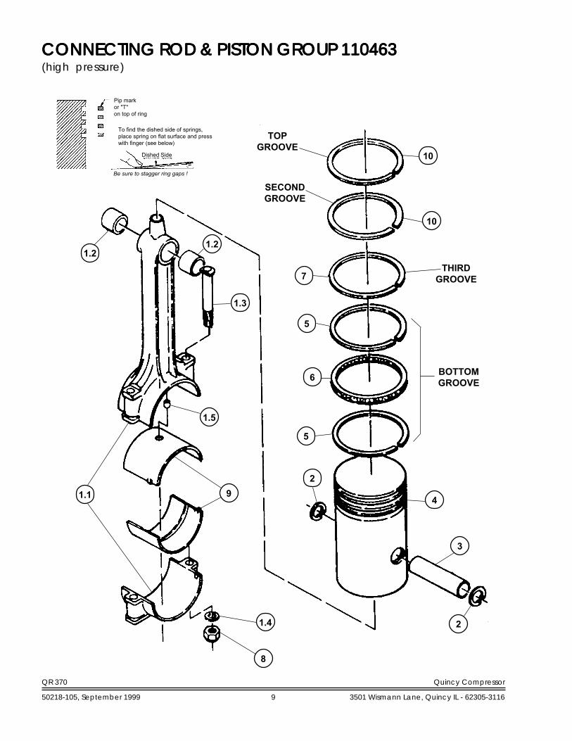
CONNECTING ROD & PISTON GROUP 110463CONNECTING ROD & PISTON GROUP 110463CONNECTING ROD & PISTON GROUP 110463CONNECTING ROD & PISTON GROUP 110463CONNECTING ROD & PISTON GROUP 110463(high pressure)
8
1.4
1.1
1.5
9
1.3
1.21.2
10
10
7
5
6
5
2
4
3
2
TOPGROOVE
SECONDGROOVE
THIRDGROOVE
BOTTOMGROOVE
Pip markor "T"on top of ring
To find the dished side of springs,place spring on flat surface and presswith finger (see below)
Be sure to stagger ring gaps !
Dished Side

QR 370 Quincy Compressor
50218-105, September 1999 10 3501 Wismann Lane, Quincy IL - 62305-3116
CONNECTING ROD & PISTON GROUP 110463CONNECTING ROD & PISTON GROUP 110463CONNECTING ROD & PISTON GROUP 110463CONNECTING ROD & PISTON GROUP 110463CONNECTING ROD & PISTON GROUP 110463(high pressure)
ItemItemItemItemItem PartPartPartPartPartNumberNumberNumberNumberNumber Qty.Qty.Qty.Qty.Qty. NumberNumberNumberNumberNumber DescriptionDescriptionDescriptionDescriptionDescription
1 1 110804 connecting rod assembly (N.S.S.; order 110804X)1.1 1 110802 connecting rod (N.S.S.; order 110804X)1.2 2 110799-010 needle bearing1.3 2 1344 connecting rod bolt, 7/16-20 unc x 3.251.4 2 1319 connecting rod bolt washer1.5 1 110801-001 plug orifice
2 2 8648 retaining ring3 1 110190-004 piston pin4 1 5846-001 piston, HP5 2 112782 oil ring rail6 1 112783 ring spacer7 1 6997 piston ring8 2 124471-M08 locknut, 7/16-20 unf (@ 40 ft.-lbs.)9 2 6656 connecting rod insert (sold in pairs only; see maintenance parts)10 2 111845 piston ring
9 1 6656PR connecting rod inserts (1 pair, standard size)9 1 6656-010PR connecting rod inserts (1 pair, .010 undersize)4 1 5846-011 piston, HP (.010 oversize)4 1 5846-021 piston, HP (.020 oversize)
8168A Ring Set-Piston, HP (Standard) No Color Codeincludes piston rings, piston rails & spacer
5788-010 Ring Set-Piston, HP (.010 Oversize) (L. Blue)includes all rings necessary for installing .010 oversize piston
5788-020 Ring Set-Piston, HP (.020 Oversize) (Yellow)includes all rings necessary for installing .020 oversize piston
5846X001 Piston Assembly, HP (Standard)includes ring set, piston, piston pin & retaining ring
5846X011 Piston Assembly, HP (.010 Oversize)includes ring set, piston, piston pin & retaining ring
5846X021 Piston Assembly, HP (.020 Oversize)includes ring set, piston, piston pin & retaining ring
110804X Replacement Connecting Rod Assembly (Standard)includes connecting rod assembly, connecting rod inserts & locknuts
110804X010 Replacement Connecting Rod Assembly (.010 Undersize)includes connecting rod assembly, connecting rod inserts & locknuts
Maintenance PartsMaintenance PartsMaintenance PartsMaintenance PartsMaintenance Parts**
N.S.S. = Not Sold Separate@ Indicates torque value (dry threads). Tighten multiple bolts, capscrews & hex nuts in a criss-cross or alternating pattern. Bring
each fastener to the recommended torque specification in even increments.* One pair required for each connecting rod assembly.
QR 370 Quincy Compressor
50218-105, September 1999 11 3501 Wismann Lane, Quincy IL - 62305-3116
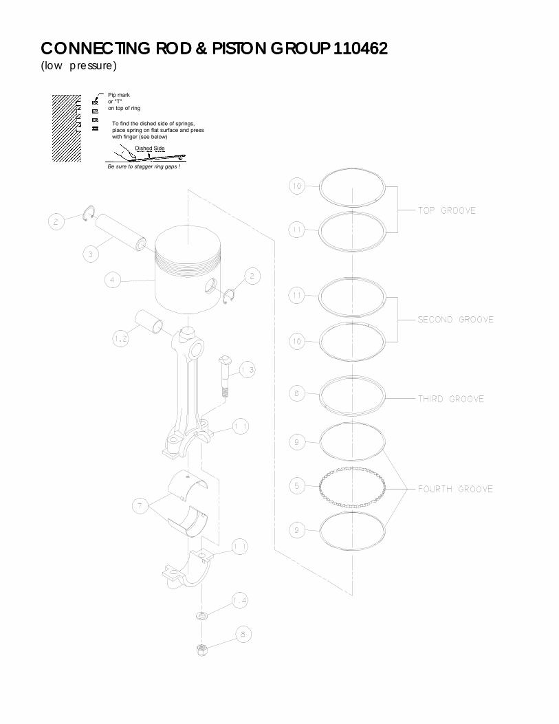
CONNECTING ROD & PISTON GROUP 110462CONNECTING ROD & PISTON GROUP 110462CONNECTING ROD & PISTON GROUP 110462CONNECTING ROD & PISTON GROUP 110462CONNECTING ROD & PISTON GROUP 110462(low pressure)
Pip markor "T"on top of ring
To find the dished side of springs,place spring on flat surface and presswith finger (see below)
Be sure to stagger ring gaps !
Dished Side

QR 370 Quincy Compressor
50218-105, September 1999 12 3501 Wismann Lane, Quincy IL - 62305-3116
CONNECTING ROD & PISTON GROUP 110462CONNECTING ROD & PISTON GROUP 110462CONNECTING ROD & PISTON GROUP 110462CONNECTING ROD & PISTON GROUP 110462CONNECTING ROD & PISTON GROUP 110462(low pressure)
ItemItemItemItemItem PartPartPartPartPartNumberNumberNumberNumberNumber Qty.Qty.Qty.Qty.Qty. NumberNumberNumberNumberNumber DescriptionDescriptionDescriptionDescriptionDescription
1 1 40081 connecting rod assembly (N.S.S.; order 6655X)1.1 1 110803 connecting rod (N.S.S.; order 6655X)1.2 1 6443 bushing, connecting rod (N.S.S.; order 6443SR)1.3 2 1344 connecting rod bolt, 7/16-20 unc x 3.251.4 2 1319 connecting rod bolt washer
2 2 8648 retaining ring3 1 8647 piston pin4 1 8640 piston, LP5 1 112749 ring spacer6 1 9146 piston ring7 2 6656 connecting rod insert (sold in pairs only; see maintenance parts)8 2 124471-M08 locknut, 7/16-20 unf (@ 40 ft.-lbs.)9 2 112748 oil ring rail10 2 6994 spring11 2 6992 piston ring
7 1 6656PR connecting rod inserts (1 pair, standard size)7 1 6656-010PR connecting rod inserts (1 pair, .010 undersize)4 1 8640-010 piston, LP (.010 oversize)4 1 8640-020 piston, LP (.020 oversize)
1 7527 Piston Ring Set, LPincludes piston rings, piston rails, piston spring & spacer
1 5787-010 Piston Ring Set, LPincludes all rings necessary for installing .010 oversize piston
1 5787-020 Piston Ring Set, LPincludes all rings necessary for installing .020 oversize piston
8640X Piston Assembly, LP (Standard)includes ring set, piston, piston pin & retaining ring
8640X010 Piston Assembly, LP (.010 Oversize)includes ring set, piston, piston pin & retaining rings
8640X020 Piston Assembly, LP (.020 Oversize)includes ring set, piston, piston pin & retaining rings
6655X Replacement Connecting Rod Assembly (Standard)includes connecting rod assembly, connecting rod inserts & locknuts
6655XUS Replacement Connecting Rod Assembly (.010 Undersize)includes connecting rod assembly, connecting rod inserts & locknuts
Maintenance PartsMaintenance PartsMaintenance PartsMaintenance PartsMaintenance Parts**
N.S.S. = Not Sold Separate@ Indicates torque value (dry threads). Tighten multiple bolts, capscrews & hex nuts in a criss-cross or alternating pattern. Bring
each fastener to the recommended torque specification in even increments.* One pair required for each connecting rod assembly.

QR 370 Quincy Compressor
50218-105, September 1999 13 3501 Wismann Lane, Quincy IL - 62305-3116
CYLINDER & HEAD GROUP 110633-001CYLINDER & HEAD GROUP 110633-001CYLINDER & HEAD GROUP 110633-001CYLINDER & HEAD GROUP 110633-001CYLINDER & HEAD GROUP 110633-001(control version P)
16
23
QR 370 Quincy Compressor
50218-105, September 1999 14 3501 Wismann Lane, Quincy IL - 62305-3116
CYLINDER & HEAD GROUP 110633-001CYLINDER & HEAD GROUP 110633-001CYLINDER & HEAD GROUP 110633-001CYLINDER & HEAD GROUP 110633-001CYLINDER & HEAD GROUP 110633-001(control version P)
ItemItemItemItemItem PartPartPartPartPartNumberNumberNumberNumberNumber Qty.Qty.Qty.Qty.Qty. NumberNumberNumberNumberNumber DescriptionDescriptionDescriptionDescriptionDescription
1 1 7382P-003 head assembly, standard pressure (see page 18 for parts breakdown)2 1 7403 gasket, cylinder to head3 1 8262-1 cylinder4 1 5827 gasket, cylinder to crankcase5 1 5860 gasket, intercooler to head6 1 5857-001 intercooler7 2 5828 gasket, companion flange8 1 5501 discharge flange9 1 5858 intake flange10 8 123478-M15 hex. screw, 7/16-14 unc x 1.50, grade 5 (@ 50 ft.-lbs.)11 1 110377F200 air filter
or11 1 110377H200 hooded air filter
or11 1 110377S200 hooded air filter silencer12 20 123115-08C lockwasher, 1/213 5 123478-N16 hex. screw, 1/2-13 unc x 1.75, grade 5 (intercooler to head: @ 65 ft.-lbs.)14 6 1478-1 flatwasher15 6 5863 counterbore screw, 1/2-13 unc x 4.25, grade 8 (@ 65 ft.-lbs.)16 14 123478-N15 hex screw, 1/2-13 unc x 1.50, grade 5 (head to cyl.: @ 65 ft.-lbs.)
(cyl. to c'case: @ 75 ft.-lbs.)17 1 90386-N14 counterbore screw, 1/2-13 unc x 1.25, grade 8 (@ 65 ft.-lbs.)18 1 123115-06C lockwasher, 3/819 1 110428W038 flatwasher-3/820 1 123478-L11 hex. screw, 3/8-16 unc x .88, grade 5 (@ 30 ft.-lbs.)21 1 2728 tube fitting, 90° male elbow, 3/8 tube x 3/8 npt22 2 ft. 110515-038 copper tube, 3/8 o.d.
23 1 110377E200 air filter element7382X16P Replacement Head Assembly
includes head assembly, intercooler gasket & head gasket
Maintenance PartsMaintenance PartsMaintenance PartsMaintenance PartsMaintenance Parts
* High pressure compressors require 7382HPS head in lieu of 7382 head. See page 18 for parts breakdown.N.S.S. = Not Sold Separate
@ Indicates torque value (dry threads). Tighten multiple bolts, capscrews & hex nuts in a criss-cross or alternating pattern. Bringeach fastener to the recommended torque specification in even increments.
*

QR 370 Quincy Compressor
50218-105, September 1999 15 3501 Wismann Lane, Quincy IL - 62305-3116
CYLINDER & HEAD GROUP 110634-001CYLINDER & HEAD GROUP 110634-001CYLINDER & HEAD GROUP 110634-001CYLINDER & HEAD GROUP 110634-001CYLINDER & HEAD GROUP 110634-001(control versions L, S, LS, & LVD)
16
13
22
11

QR 370 Quincy Compressor
50218-105, September 1999 16 3501 Wismann Lane, Quincy IL - 62305-3116
CYLINDER & HEAD GROUP 110634-001CYLINDER & HEAD GROUP 110634-001CYLINDER & HEAD GROUP 110634-001CYLINDER & HEAD GROUP 110634-001CYLINDER & HEAD GROUP 110634-001(control versions L, S, LS, & LVD)
ItemItemItemItemItem PartPartPartPartPartNumberNumberNumberNumberNumber Qty.Qty.Qty.Qty.Qty. NumberNumberNumberNumberNumber DescriptionDescriptionDescriptionDescriptionDescription
1 1 7382UU-003 head assembly (see pages 20 & 22 for parts breakdown)2 1 7403 gasket, cylinder to head3 1 8262-1 cylinder4 1 5827 gasket, cylinder to crankcase5 1 5860 gasket, intercooler to head6 1 5857-001 intercooler7 2 5828 gasket, companion flange8 1 5501 discharge flange9 1 5858 intake flange10 8 123478-M15 hex. screw, 7/16-14 unc x 1.50, grade 5 (@ 50 ft.-lbs.)11 2 ft. 110515-038 copper tube, 3/8 o.d.12 20 123115-08C lockwasher, 1/213 5 123478-N16 hex. screw, 1/2-13 unc x 1.75, grade 5 (@ 65 ft.-lbs.)14 6 1478-1 flatwasher15 6 5863 counterbore screw, 1/2-13 unc x 4.25, grade 8 (@ 65 ft.-lbs.)16 14 123478-N15 hex screw, 1/2-13 unc x 1.50, grade 5 (cyl. to c'case: @ 75 ft.-lbs.)
(head to cyl.: @ 65 ft.-lbs.)17 1 90386-N14 counterbore screw, 1/2-13 unc x 1.25, grade 8 (@ 65 ft.-lbs.)18 1 123115-06C lockwasher, 3/819 1 110428W038 flatwasher-3/820 1 123478-L11 hex. screw, 3/8-16 unc x .88, grade 5 (@ 30 ft.-lbs.)21 1 2728 tube fitting, 90° male elbow, 3/8 tube x 3/8 npt22 1 110377F200 air filter
or22 1 110377H200 hooded air filter
or22 1 110377S200 hooded air filter silencer
23 1 110377E200 air filter element7382X16L Replacement Head Assembly
includes head assembly & intercooler & head gaskets
Maintenance PartsMaintenance PartsMaintenance PartsMaintenance PartsMaintenance Parts
* High pressure compressors require 7382HPS head in lieu of 7382 head. See page 20 for parts breakdown.N.S.S. = Not Sold Separate
@ Indicates torque value (dry threads). Tighten multiple bolts, capscrews & hex nuts in a criss-cross or alternating pattern. Bringeach fastener to the recommended torque specification in even increments.
*
QR 370 Quincy Compressor
50218-105, September 1999 17 3501 Wismann Lane, Quincy IL - 62305-3116
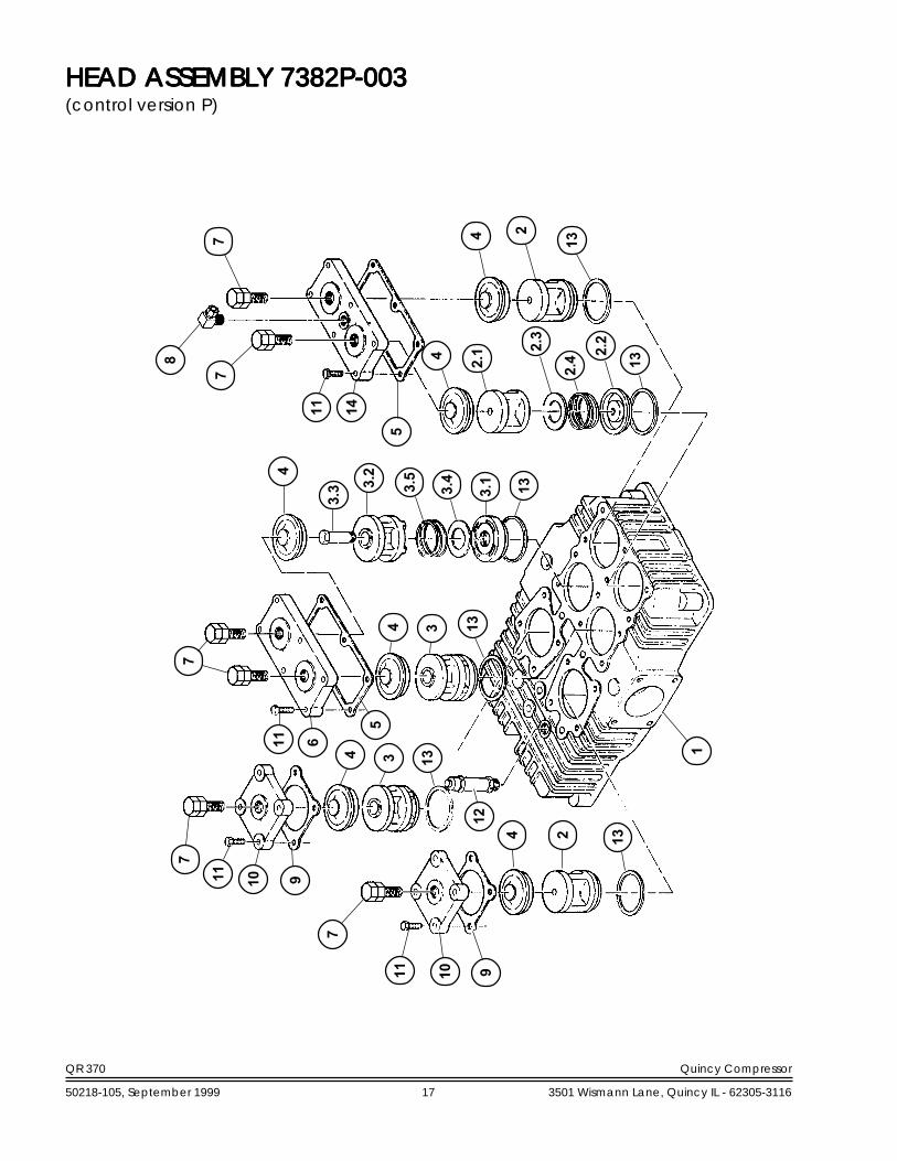
HEAD ASSEMBLY 7382P-003HEAD ASSEMBLY 7382P-003HEAD ASSEMBLY 7382P-003HEAD ASSEMBLY 7382P-003HEAD ASSEMBLY 7382P-003(control version P)
7
11 10 9
4 2 13
7
11 10 9
4 3 13
11 6
54 3 13
4
3.2
3.5
3.4
3.1 13
5
12
2.3
2.4 2.2
13
7
11 14
8
7 4 2
13
1
4 2.1
7
3.3

QR 370 Quincy Compressor
50218-105, September 1999 18 3501 Wismann Lane, Quincy IL - 62305-3116
HEAD ASSEMBLY 7382P-003HEAD ASSEMBLY 7382P-003HEAD ASSEMBLY 7382P-003HEAD ASSEMBLY 7382P-003HEAD ASSEMBLY 7382P-003(control version P)
ItemItemItemItemItem PartPartPartPartPartNumberNumberNumberNumberNumber Qty.Qty.Qty.Qty.Qty. NumberNumberNumberNumberNumber DescriptionDescriptionDescriptionDescriptionDescription
1 1 7382 head, standard pressure (part of 7382P-002)2 3 7749X1 suction valve assembly
2.1 1 7749 valve seat2.2 1 7751 valve bumper2.3 1 7753 valve disc2.4 1 6909 valve spring
3 3 7750X1 discharge valve assembly3.1 1 7750 valve seat3.2 1 7752 valve bumper3.3 1 5746 valve post3.4 1 7753 valve disc3.5 1 6909 valve spring
4 6 6668-1R valve retainer5 2 7398 valve cover gasket6 1 7384 cover plate7 6 114545-R15 bolt & nut assembly, 3/4-16 unf x 1.50, grade 5 (@ 60 ft.-lbs.)8 1 2614 tube fitting, 90° male elbow, 3/8 tube x 1/4 npt9 2 2025 valve cover gasket10 2 6666 cover plate11 20 7480 hex. screw, 7/16-14 unc x 1.38, grade 5 (@ 50 ft.-lbs.)12 1 2961-100 relief valve13 6 2024 valve gasket14 1 7384-001 suction valve plate
3 7749X Replacement Suction Valve Assemblyincludes suction valve assembly & valve gasket
3 7750X Replacement Discharge Valve assemblyincludes discharge valve assembly & valve gasket
*
‡
‡
Maintenance PartsMaintenance PartsMaintenance PartsMaintenance PartsMaintenance Parts
* High pressure compressors require 7382HPS head in lieu of 7382 head.‡ Tighten & torque valve cover plate screws (item 11) before tightening vlave clamp screws (item 7).@ Indicates torque value (dry threads). Tighten multiple bolts, capscrews & hex nuts in a criss-cross or alternating pattern. Bring
each fastener to the recommended torque specification in even increments.

QR 370 Quincy Compressor
50218-105, September 1999 19 3501 Wismann Lane, Quincy IL - 62305-3116
30
1325
19.3
13
19.2
25
6 2
2.1
11
3029
27
16.3
HEAD ASSEMBLY 7382UU-003HEAD ASSEMBLY 7382UU-003HEAD ASSEMBLY 7382UU-003HEAD ASSEMBLY 7382UU-003HEAD ASSEMBLY 7382UU-003(control versions L, S, LS, & LVD)
28
10 9
8 2.3
2.4 2.2
25
4 3
726
16.5
16.2 16.4
16.1
15 251419.1
8
5
1
8 19
2519.4
19.5
11
1720
259
18
11
17
22 21
17
8 19
23 21 7
6
345
2
24.1
15
14
24.3
24.5
24.2 24.4
12

QR 370 Quincy Compressor
50218-105, September 1999 20 3501 Wismann Lane, Quincy IL - 62305-3116
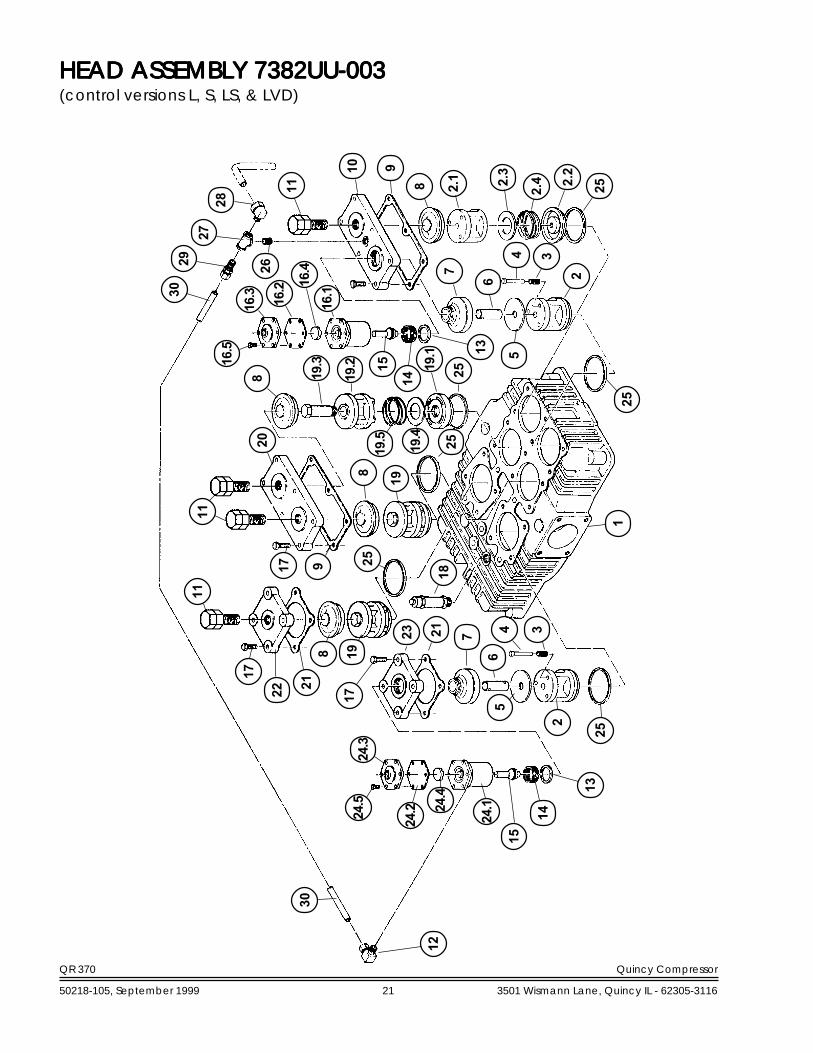
HEAD ASSEMBLHEAD ASSEMBLHEAD ASSEMBLHEAD ASSEMBLHEAD ASSEMBLY 7382UU-003Y 7382UU-003Y 7382UU-003Y 7382UU-003Y 7382UU-003(control versions L, S, LS, & LVD)
ItemItemItemItemItem PartPartPartPartPartNumberNumberNumberNumberNumber Qty.Qty.Qty.Qty.Qty. NumberNumberNumberNumberNumber DescriptionDescriptionDescriptionDescriptionDescription
1 1 7382 head2 3 7749X1 suction valve assembly
2.1 1 7749 valve seat2.2 1 7751 valve bumper2.3 1 7753 valve disc2.4 1 6909 valve spring
3 6 6910 valve spring4 6 1857 valve pin5 2 5729 valve platform6 2 6912-001 unloader pin7 2 6911 valve retainer8 4 6668-1R valve retainer9 2 7398 valve cover gasket10 1 7385 valve cover plate11 4 114545-R15 bolt & nut assembly, 3/4-16 unf x 1.50, grade 5 (60 ft.-lbs.)12 1 1642 tube fitting, 90° male elbow, 1/4 tube x 1/8 npt13 2 1556 gasket14 2 3008 holddown screw/ (@ 60 ft.-lbs.)15 2 7532X unloader piston assembly16 1 40192 unloader assembly (@ 75 ft.-lbs.), (N.S.S.; order 8272X)
16.1 1 8272 unloader body16.2 1 1855 diaphragm16.3 1 1818B diaphragm cover plate16.4 1 5910 diaphragm disc16.5 6 7499 hex. screw, 1/4-20 unc x .75, grade 5 (@ 6 ft.-lbs.)
17 20 7480 hex. screw, 7/16-14 unc x 1.38, grade 5 (@ 50 ft.-lbs.)18 1 2961-100 relief valve19 3 7750X1 discharge valve assembly
19.1 1 7750 valve seat19.2 1 7752 valve bumper19.3 1 5746 valve post19.4 1 7753 valve disc19.5 1 6909 valve spring
20 1 7384 cover plate21 2 2025 valve cover gasket22 2 6666 cover plate23 1 6908 cover plate24 1 40055 unloader assembly (@ 75 ft.-lbs.) (N.S.S.; order 7483X)
24.1 1 7483 unloader body24.2 1 1855 diaphragm24.3 1 1818B diaphragm cover plate24.4 1 5910 diaphragm disc24.5 6 7499 hex. screw, 1/4-20 unc x .75, grade 5 (@ 6 ft.-lbs.)
25 6 2024 valve gasket26 1 125933-001 pipe nipple, 1/4 npt x close27 1 4574 pipe tee, 1/4 npt x 1/4 npt x 1/4 npt28 1 2614 tube fitting, 90° male elbow, 3/8 tube x 1/4 npt29 1 110594-005 tube fitting, male connector, 1/4 tube x 1/4 npt30 1 ft. 110515-025 copper tube, 1/4 o.d.
‡
‡
CONTINUED ON PAGE 22
‡ Tighten & torque valve cover plate screws (item 11) before tightening vlave clamp screws (item 17).@ Indicates torque value (dry threads). Tighten multiple bolts, capscrews & hex nuts in a criss-cross or alternating pattern. Bring
each fastener to the recommended torque specification in even increments.N.S.S. = Not Sold Separate
QR 370 Quincy Compressor
50218-105, September 1999 21 3501 Wismann Lane, Quincy IL - 62305-3116
HEAD ASSEMBLY 7382UU-003HEAD ASSEMBLY 7382UU-003HEAD ASSEMBLY 7382UU-003HEAD ASSEMBLY 7382UU-003HEAD ASSEMBLY 7382UU-003(control versions L, S, LS, & LVD)
30
1325
19.3
13
19.2
25
6 2
2.1
11
3029
27
16.3
28
10 9
8 2.3
2.4 2.2
25
4 3
726
16.5
16.2 16.4
16.1
15 251419.1
8
5
1
8 19
2519.4
19.5
11
1720
259
18
11
17
22 21
17
8 19
23 21 7
6
345
2
24.1
15
14
24.3
24.5
24.2 24.4
12
QR 370 Quincy Compressor
50218-105, September 1999 22 3501 Wismann Lane, Quincy IL - 62305-3116
HEAD ASSEMBLHEAD ASSEMBLHEAD ASSEMBLHEAD ASSEMBLHEAD ASSEMBLY 7382UU-003Y 7382UU-003Y 7382UU-003Y 7382UU-003Y 7382UU-003(control versions L, S, LS, & LVD)
ItemItemItemItemItem PartPartPartPartPartNumberNumberNumberNumberNumber Qty.Qty.Qty.Qty.Qty. NumberNumberNumberNumberNumber DescriptionDescriptionDescriptionDescriptionDescription
1 7749X Replacement Suction Valve Assemblyincludes suction valve assembly & valve gasket
2 7749XU Replacement Suction Valve Assemblyincludes suction valve assembly, unloader pin springs, valve pins & valve gasket
3 7750X Replacement Discharge Valve Assemblyincludes discharge valve assembly & valve gasket
1 7483X Replacement Unloader Assemblyincludes unloader assembly, unloader piston assembly, valve gasket & pipe plug
1 8272X Replacement Unloader Assemblyincludes unloader piston assembly, unloader assembly, & valve gasket
Maintenance PartsMaintenance PartsMaintenance PartsMaintenance PartsMaintenance Parts
QR 370 Quincy Compressor
50218-105, September 1999 23 3501 Wismann Lane, Quincy IL - 62305-3116
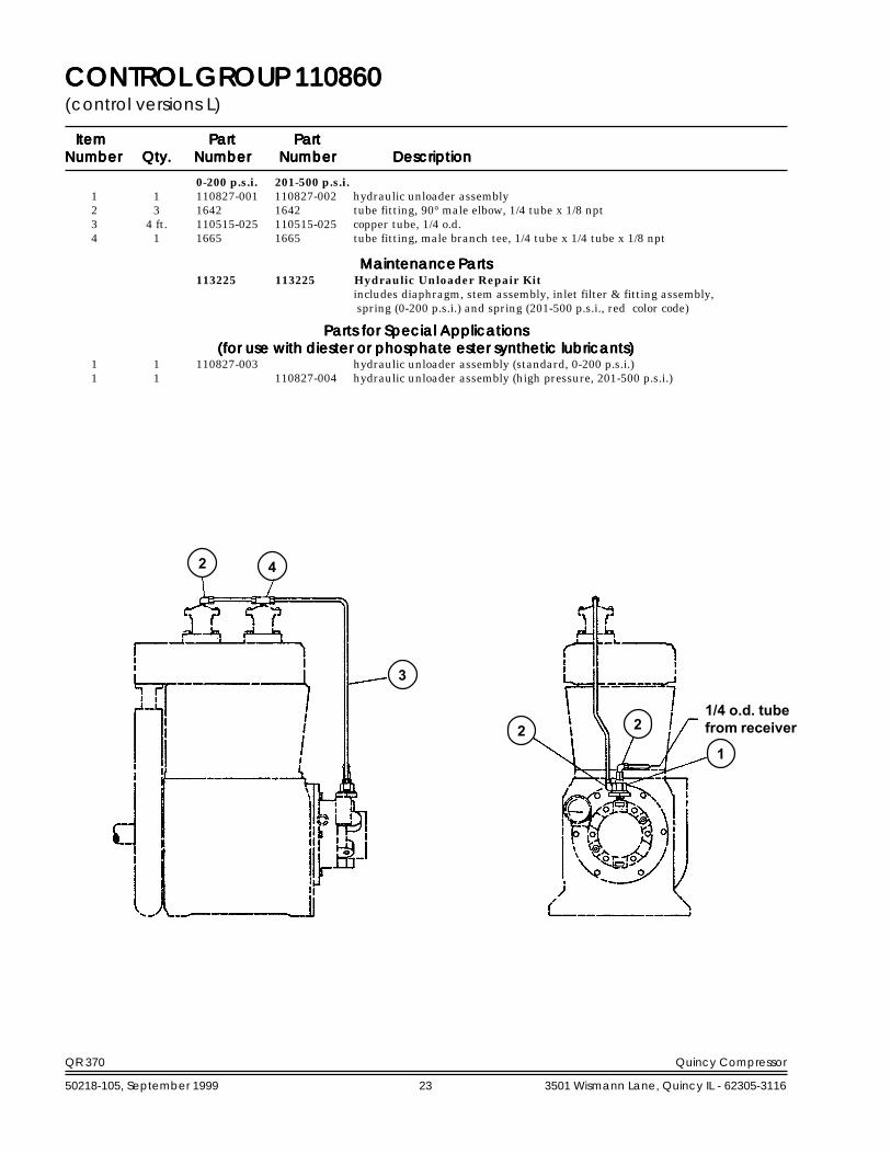
CONTROL GROUP 110860CONTROL GROUP 110860CONTROL GROUP 110860CONTROL GROUP 110860CONTROL GROUP 110860(control versions L)
ItemItemItemItemItem PartPartPartPartPart PartPartPartPartPartNumberNumberNumberNumberNumber Qty.Qty.Qty.Qty.Qty. NumberNumberNumberNumberNumber NumberNumberNumberNumberNumber DescriptionDescriptionDescriptionDescriptionDescription
0-200 p.s.i. 201-500 p.s.i.1 1 110827-001 110827-002 hydraulic unloader assembly2 3 1642 1642 tube fitting, 90° male elbow, 1/4 tube x 1/8 npt3 4 ft. 110515-025 110515-025 copper tube, 1/4 o.d.4 1 1665 1665 tube fitting, male branch tee, 1/4 tube x 1/4 tube x 1/8 npt
113225 113225 Hydraulic Unloader Repair Kitincludes diaphragm, stem assembly, inlet filter & fitting assembly, spring (0-200 p.s.i.) and spring (201-500 p.s.i., red color code)
1 1 110827-003 hydraulic unloader assembly (standard, 0-200 p.s.i.)1 1 110827-004 hydraulic unloader assembly (high pressure, 201-500 p.s.i.)
2 4
3
21
21/4 o.d. tubefrom receiver
Maintenance PartsMaintenance PartsMaintenance PartsMaintenance PartsMaintenance Parts
Parts for Special ApplicationsParts for Special ApplicationsParts for Special ApplicationsParts for Special ApplicationsParts for Special Applications(for use with diester or phosphate ester synthetic lubricants)(for use with diester or phosphate ester synthetic lubricants)(for use with diester or phosphate ester synthetic lubricants)(for use with diester or phosphate ester synthetic lubricants)(for use with diester or phosphate ester synthetic lubricants)

QR 370 Quincy Compressor
50218-105, September 1999 24 3501 Wismann Lane, Quincy IL - 62305-3116
0-200 p.s.i. 201-500 p.s.i.1 1 110844 110844-999 pilot valve assembly
1.1 1 110832-140 110832-999 pilot valve1.2 1 2616 2616 tube fitting, straight male connector, 3/8 tube x 1/4 npt1.3 1 6317 6317 mounting stud1.4 4 160047-J05 160047-J05 set screw, 1/4-28 unf x .38, grade 51.5 1 2719 2719 pipe plug, 1/4 npt, hex socket
2 4 ft. 110515-025 110515-025 copper tube, 1/4 o.d.3 1 1665 1665 tube fitting, male branch tee, 1/4 tube x 1/4 tube x 1/8 npt4 1 1642 1642 tube fitting, 90° male elbow, 1/4 tube x 1/8 npt5 1 2708 2708 tube fitting, 90° male elbow, 1/4 tube x 1/4 npt
CONTROL GROUP 110857CONTROL GROUP 110857CONTROL GROUP 110857CONTROL GROUP 110857CONTROL GROUP 110857(control version S)
ItemItemItemItemItem PartPartPartPartPart PartPartPartPartPartNumberNumberNumberNumberNumber Qty.Qty.Qty.Qty.Qty. NumberNumberNumberNumberNumber NumberNumberNumberNumberNumber DescriptionDescriptionDescriptionDescriptionDescription
* See page 27 for optional pilot valves that must be used with respective pressure ranges.
*
23
2
1.5 1.1
4
5
1.4
1.3
1.23/8 o.d. tubefrom receiver

QR 370 Quincy Compressor
50218-105, September 1999 25 3501 Wismann Lane, Quincy IL - 62305-3116
CONTROL GROUP 110858CONTROL GROUP 110858CONTROL GROUP 110858CONTROL GROUP 110858CONTROL GROUP 110858(control version LS)
0-200 p.s.i. 201-500 p.s.i.1 1 110845 110845-001 pilot valve assembly
1.1 1 111422-175 111422-999 pilot valve1.2 1 110827-001 110827-002 hydraulic unloader assembly1.3 1 6317 6317 mounting stud1.4 1 160047-J05 160047-J05 set screw, 1/4-28 unf x .38, grade 51.5 1 7361 7361 brass pipe tee, 1/4 npt x 1/4 npt x 1/4 npt1.6 2 1642 1642 tube fitting, 90° male elbow, 1/4 tube x 1/8 npt1.7 1 ft. 110515-025 110515-025 copper tube, 1/4 o.d.1.8 1 124393-004 124393-004 tube fitting, straight male connector, 1/4 tube x 1/8 npt1.9 1 2708 2708 tube fitting, 90° male elbow, 1/4 tube x 1/4 npt1.10 1 2616 2616 tube fitting, straight male connector, 3/8 tube x 1/4 npt
2 4 ft. 110515-025 110515-025 copper tube, 1/4 o.d.3 1 1665 1665 tube fitting, male branch tee, 1/4 tube x 1/4 tube x 1/8 npt4 1 1642 1642 tube fitting, 90° male elbow, 1/4 tube x 1/8 npt5 1 2708 2708 tube fitting, 90° male elbow, 1/4 tube x 1/4 npt
113225 113225 Hydraulic Unloader Repair Kitincludes diaphragm, stem assembly, inlet filter & fitting assembly,spring (0-200 p.s.i.) and spring (201-500 p.s.i. red color code)
1 1 110827-003 hydraulic unloader assembly (standard, 0-200 p.s.i.)1 1 110827-004 hydraulic unloader assembly (high pressure, 201-500 p.s.i.)
ItemItemItemItemItem PartPartPartPartPart PartPartPartPartPartNumberNumberNumberNumberNumber Qty.Qty.Qty.Qty.Qty. NumberNumberNumberNumberNumber NumberNumberNumberNumberNumber DescriptionDescriptionDescriptionDescriptionDescription
Maintenance PartsMaintenance PartsMaintenance PartsMaintenance PartsMaintenance Parts
Parts for Special ApplicationsParts for Special ApplicationsParts for Special ApplicationsParts for Special ApplicationsParts for Special Applications(for use with diester or phosphate ester synthetic lubricants)(for use with diester or phosphate ester synthetic lubricants)(for use with diester or phosphate ester synthetic lubricants)(for use with diester or phosphate ester synthetic lubricants)(for use with diester or phosphate ester synthetic lubricants)
4 3
2 1.1
3/8 o.d. tubefrom receiver1.3
1.4
1.61.61.8
5
1.10
1.51.2
1.7
1.9
* See page 27 for optional pilot valves that must be used with respective pressure ranges.
1.7
QR 370 Quincy Compressor
50218-105, September 1999 26 3501 Wismann Lane, Quincy IL - 62305-3116
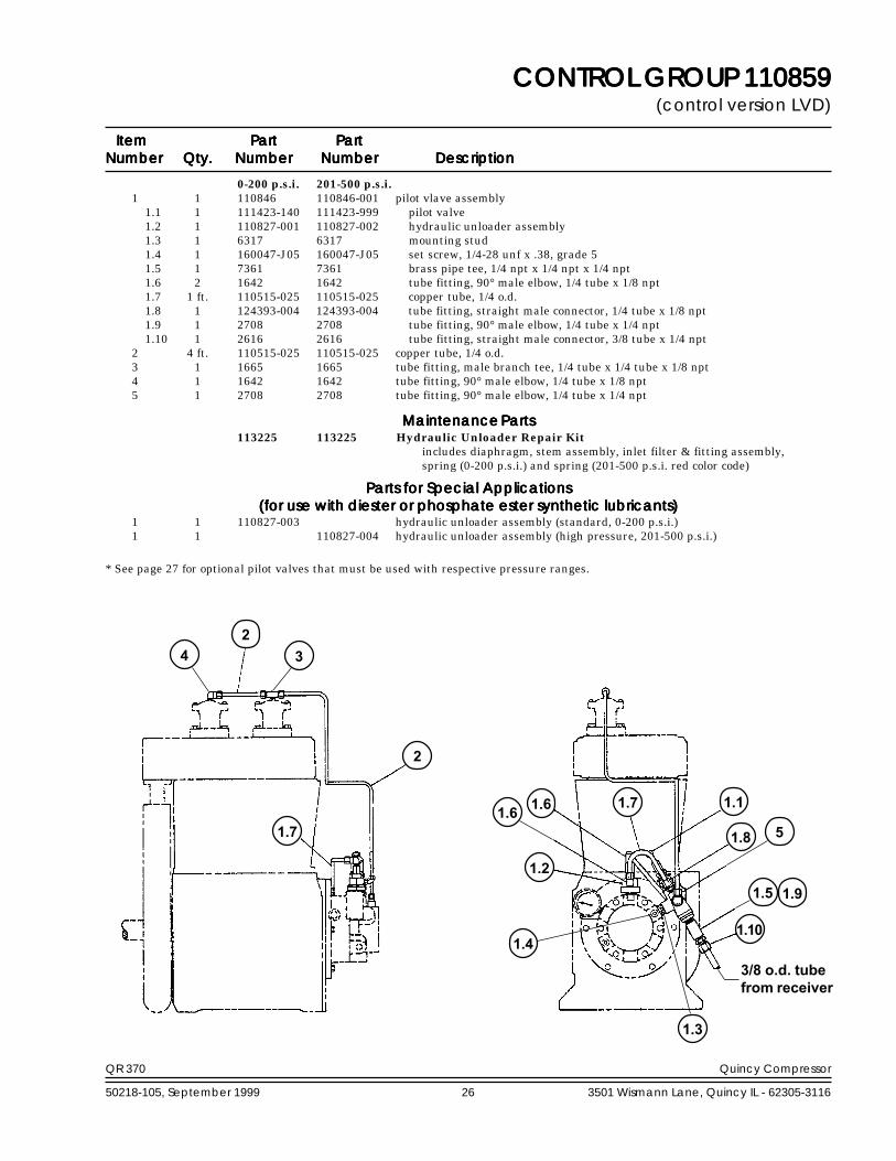
CONTROL GROUP 110859CONTROL GROUP 110859CONTROL GROUP 110859CONTROL GROUP 110859CONTROL GROUP 110859(control version LVD)
ItemItemItemItemItem PartPartPartPartPart PartPartPartPartPartNumberNumberNumberNumberNumber Qty.Qty.Qty.Qty.Qty. NumberNumberNumberNumberNumber NumberNumberNumberNumberNumber DescriptionDescriptionDescriptionDescriptionDescription
0-200 p.s.i. 201-500 p.s.i.1 1 110846 110846-001 pilot vlave assembly
1.1 1 111423-140 111423-999 pilot valve1.2 1 110827-001 110827-002 hydraulic unloader assembly1.3 1 6317 6317 mounting stud1.4 1 160047-J05 160047-J05 set screw, 1/4-28 unf x .38, grade 51.5 1 7361 7361 brass pipe tee, 1/4 npt x 1/4 npt x 1/4 npt1.6 2 1642 1642 tube fitting, 90° male elbow, 1/4 tube x 1/8 npt1.7 1 ft. 110515-025 110515-025 copper tube, 1/4 o.d.1.8 1 124393-004 124393-004 tube fitting, straight male connector, 1/4 tube x 1/8 npt1.9 1 2708 2708 tube fitting, 90° male elbow, 1/4 tube x 1/4 npt1.10 1 2616 2616 tube fitting, straight male connector, 3/8 tube x 1/4 npt
2 4 ft. 110515-025 110515-025 copper tube, 1/4 o.d.3 1 1665 1665 tube fitting, male branch tee, 1/4 tube x 1/4 tube x 1/8 npt4 1 1642 1642 tube fitting, 90° male elbow, 1/4 tube x 1/8 npt5 1 2708 2708 tube fitting, 90° male elbow, 1/4 tube x 1/4 npt
113225 113225 Hydraulic Unloader Repair Kitincludes diaphragm, stem assembly, inlet filter & fitting assembly,spring (0-200 p.s.i.) and spring (201-500 p.s.i. red color code)
1 1 110827-003 hydraulic unloader assembly (standard, 0-200 p.s.i.)1 1 110827-004 hydraulic unloader assembly (high pressure, 201-500 p.s.i.)
Maintenance PartsMaintenance PartsMaintenance PartsMaintenance PartsMaintenance Parts
Parts for Special ApplicationsParts for Special ApplicationsParts for Special ApplicationsParts for Special ApplicationsParts for Special Applications(for use with diester or phosphate ester synthetic lubricants)(for use with diester or phosphate ester synthetic lubricants)(for use with diester or phosphate ester synthetic lubricants)(for use with diester or phosphate ester synthetic lubricants)(for use with diester or phosphate ester synthetic lubricants)
* See page 27 for optional pilot valves that must be used with respective pressure ranges.
2
1.8
1.10
1.5
1.1
1.2
1.6
51.6 1.7
1.4
1.3
1.9
1.7
2
4 3
3/8 o.d. tubefrom receiver

QR 370 Quincy Compressor
50218-105, September 1999 27 3501 Wismann Lane, Quincy IL - 62305-3116
PILOT VPILOT VPILOT VPILOT VPILOT VALALALALALVESVESVESVESVES
110832 series pilot valve (control version S)
toggle leverunload adjustment
differential adjustment
air fromreceiver
2
1 3 4
differential adjustment
toggle leverunload adjustment
airfrom
receiver
1
2 43
111422 series pilot valve (control version LS)
1
432
unload adjustment
differential adjustment
airinlet
111423 series pilot valve (control version LVD)
WARNING !Not all pilots are for usewith all compressor systems. Makesure that the pilot you order is set within the safe operatinglimits of your compressor. Failure to heed this warningcould result in an explosion.
checkball
checkball
air in from hydraulicunloader
air out to headunloaders
5
5
air in from hydraulicunloader
checkball
knurledknob
air out to headunloaders
air out tohead unloaders
Refer to illustrations at left to determine pilot valve series; adddash # listed below per pressure setting.
-997 30-70 adjustable unload pressure /customer to set, see differen-tial setting chart
-998 71-100 adjustable unload pressure /customer to set, see differen-tial setting chart
-998 71-100 adjustable unload pressure /customer to set, see differen-tial setting chart
Pressure SettingPressure SettingPressure SettingPressure SettingPressure SettingDash #Dash #Dash #Dash #Dash # (p.s.i.)(p.s.i.)(p.s.i.)(p.s.i.)(p.s.i.) NotesNotesNotesNotesNotes
Available Pilot Valves
Additional factory preset valves are available upon request.
Spring Part #Spring Part #Spring Part #Spring Part #Spring Part # UnloadUnloadUnloadUnloadUnload Min. Dif.Min. Dif.Min. Dif.Min. Dif.Min. Dif. Max. Dif.Max. Dif.Max. Dif.Max. Dif.Max. Dif.(item 4)(item 4)(item 4)(item 4)(item 4) (p.s.i.)(p.s.i.)(p.s.i.)(p.s.i.)(p.s.i.) (p.s.i.)(p.s.i.)(p.s.i.)(p.s.i.)(p.s.i.) (p.s.i.)(p.s.i.)(p.s.i.)(p.s.i.)(p.s.i.)
Differential Setting Chart
110832-052 30 2 4" 40 5 8" 50 5 8" 60 5 8" 70 5 10
110832-053 80 5 10" 90 5 12" 100 5 13" 110 5 15" 120 5 15" 130 5 18" 140 5 18" 150 5 20
110832-054 160 5 15" 170 5 20" 175 5 23" 200 5 25" 250 10 30
Can be used to repair 110832, 111422 & 111423 series pilotvalves. Customer must specify which spring when orderingpilot valve repair kit.
1 2 screen2 1 filter3 1 "o"ring4 1 110832-052 replacement spring, pilot
valve, 30-70 p.s.i. (red colorcode)
1 110832-053 replacement spring, pilotvalve, 71-150 p.s.i. (yellowcolor code)
1 110832-054 replacement spring, pilotvalve, 151-250 p.s.i. (greencolor code)
5 1 6196-003 disc
ItemItemItemItemItem PartPartPartPartPart##### Qty.Qty.Qty.Qty.Qty. NumberNumberNumberNumberNumber DescriptionDescriptionDescriptionDescriptionDescription
Pilot Valve Repair Kit 110832-051

QR 370 Quincy Compressor
50218-105, September 1999 28 3501 Wismann Lane, Quincy IL - 62305-3116
WARNING !
SUCTION VALVEUNLOADER ASSEMBLIESDescriptionThe Quincy suction valve unloader assembly con-sists of unloading arrangements on the suction valves,having a plunger to contact the suction valve discand an unloader pilot valve (part no.s 110832-***,and 111422-*** & 111423-***) to automatically regu-late the passing of receiver pressure to the unload-ing arrangement.
ApplicationSuction valve unloader assemblies are recommendedfor use on Quincy compressors where the compres-sor is to run continuously and a constant pressure isto be maintained. The purpose is to automaticallyunseat the suction valve of the compressor when theair supply is greater than the demand.
OperationUnloading occurs when receiver pressure is suffi-cient to overcome pilot valve spring pressure. Thecheck ball is then unseated, allowing receiver pres-sure to pass to the unloading arrangements. Thecompressor will run unloaded until the receiverpressure drops to a predetermined level. At thistime, the action of the ball is reversed, shutting offreceiver pressure to the unloader arrangement andventing the unloader to atmosphere. This allows thecompressor to load. The drive, either electric motoror combustion engine, runs continuously and mustbe started and stopped manually.
Pilot valve 111423-*** can be locked out, formodels equipped with dual control, to provide auto-matic start/stop operation. The knurled knob at thetop of the pilot can be turned clockwise, until it stops,to lock it out. A pressure switch is required to stopthe motor. Failure to use a pressure switch, with thepilot valve locked out, could result in unsafe condi-tions.
A pressure switch must be incorporated whenever pilotvalve 111423-*** is employed as part of the control system.
The compressor will operate in the continous runmode if the knurled knob is turned counterclockwiseuntil it stops.
InstallationThe pilot valve is to be connected to the air receiverusing a minimum of 3/8" o.d. copper tube. Compres-sors in the field, not equipped with a suction valve
unloader assembly, can be converted to constantspeed. Consult your local Quincy Compressor Dis-tributor for assistance with conversion procedures.
ServicePeriodically check the filter & screens in the inlet ofthe pilot valve to make sure they are free of obstruc-tions. If they become clogged, remove and clean orreplace. Inspect the "o"ring located in the oppositeend of the pilot valve body for wear or damage;replace if necessary.
AdjustmentThe unloading pressure is adjustable and is regu-lated by turning the hex nut (marked "unload adj."in cross sectional illustrations of pilot valves). Turnthe hex nut clockwise to increase and counterclock-wise to decrease the unloading pressure.
The differential (difference between unloadingand loading pressure) is set by turning the hex nut(marked "differential adj." in the cross sectionalillustrations of the pilot valves). Increase the differ-ential pressure by turning the hex nut clockwise -decrease by turning counterclockwise. Tighten thelocknuts after adjustment.
CHECK VCHECK VCHECK VCHECK VCHECK VALALALALALVE ASSEMBLIESVE ASSEMBLIESVE ASSEMBLIESVE ASSEMBLIESVE ASSEMBLIES
ItemItemItemItemItem PartPartPartPartPart##### Qty.Qty.Qty.Qty.Qty. NumberNumberNumberNumberNumber DescriptionDescriptionDescriptionDescriptionDescription
Check Valve Assembly Replacement Parts
6194X2 Check Valve Assembly1 1 123157-010 "o"ring2 1 6196-002 disc
6194X3 Check Valve Assembly(for use with diester or phosphate ester synthetic lubricants)
1 1 22749-010 "o"ring2 1 6196-003 disc
2
1
QR 370 Quincy Compressor
50218-105, September 1999 29 3501 Wismann Lane, Quincy IL - 62305-3116
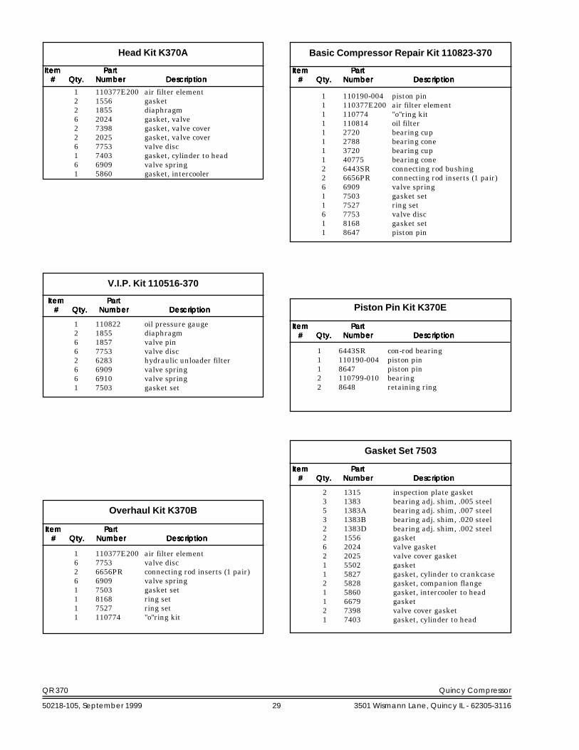
Head Kit K370A Basic Compressor Repair Kit 110823-370
1 110190-004 piston pin1 110377E200 air filter element1 110774 "o"ring kit1 110814 oil filter1 2720 bearing cup1 2788 bearing cone1 3720 bearing cup1 40775 bearing cone2 6443SR connecting rod bushing2 6656PR connecting rod inserts (1 pair)6 6909 valve spring1 7503 gasket set1 7527 ring set6 7753 valve disc1 8168 gasket set1 8647 piston pin
ItemItemItemItemItem PartPartPartPartPart##### Qty.Qty.Qty.Qty.Qty. NumberNumberNumberNumberNumber DescriptionDescriptionDescriptionDescriptionDescription
Gasket Set 7503
2 1315 inspection plate gasket3 1383 bearing adj. shim, .005 steel5 1383A bearing adj. shim, .007 steel3 1383B bearing adj. shim, .020 steel2 1383D bearing adj. shim, .002 steel2 1556 gasket6 2024 valve gasket2 2025 valve cover gasket1 5502 gasket1 5827 gasket, cylinder to crankcase2 5828 gasket, companion flange1 5860 gasket, intercooler to head1 6679 gasket2 7398 valve cover gasket1 7403 gasket, cylinder to head
Piston Pin Kit K370E
1 6443SR con-rod bearing1 110190-004 piston pin1 8647 piston pin2 110799-010 bearing2 8648 retaining ring
ItemItemItemItemItem PartPartPartPartPart##### Qty.Qty.Qty.Qty.Qty. NumberNumberNumberNumberNumber DescriptionDescriptionDescriptionDescriptionDescription
ItemItemItemItemItem PartPartPartPartPart##### Qty.Qty.Qty.Qty.Qty. NumberNumberNumberNumberNumber DescriptionDescriptionDescriptionDescriptionDescription
ItemItemItemItemItem PartPartPartPartPart##### Qty.Qty.Qty.Qty.Qty. NumberNumberNumberNumberNumber DescriptionDescriptionDescriptionDescriptionDescription
1 110377E200 air filter element2 1556 gasket2 1855 diaphragm6 2024 gasket, valve2 7398 gasket, valve cover2 2025 gasket, valve cover6 7753 valve disc1 7403 gasket, cylinder to head6 6909 valve spring1 5860 gasket, intercooler
ItemItemItemItemItem PartPartPartPartPart##### Qty.Qty.Qty.Qty.Qty. NumberNumberNumberNumberNumber DescriptionDescriptionDescriptionDescriptionDescription
Overhaul Kit K370B
1 110377E200 air filter element6 7753 valve disc2 6656PR connecting rod inserts (1 pair)6 6909 valve spring1 7503 gasket set1 8168 ring set1 7527 ring set1 110774 "o"ring kit
1 110822 oil pressure gauge2 1855 diaphragm6 1857 valve pin6 7753 valve disc2 6283 hydraulic unloader filter6 6909 valve spring6 6910 valve spring1 7503 gasket set
ItemItemItemItemItem PartPartPartPartPart##### Qty.Qty.Qty.Qty.Qty. NumberNumberNumberNumberNumber DescriptionDescriptionDescriptionDescriptionDescription
V.I.P. Kit 110516-370
QR 370 Quincy Compressor
50218-105, September 1999 30 3501 Wismann Lane, Quincy IL - 62305-3116
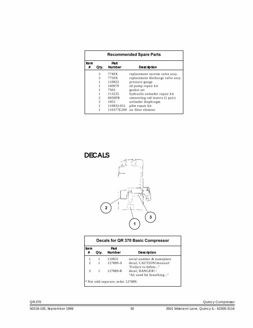
ItemItemItemItemItem PartPartPartPartPart##### Qty.Qty.Qty.Qty.Qty. NumberNumberNumberNumberNumber DescriptionDescriptionDescriptionDescriptionDescription
Recommended Spare Parts
3 7749X replacement suction valve assy.3 7750X replacement discharge valve assy.1 110822 pressure gauge1 160079 oil pump repair kit1 7503 gasket set1 113225 hydraulic unloader repair kit2 6656PR connecting rod inserts (1 pair)2 1855 unloader diaphragm1 110832-051 pilot repair kit1 110377E200 air filter element
DECALSDECALSDECALSDECALSDECALS
ItemItemItemItemItem PartPartPartPartPart##### Qty.Qty.Qty.Qty.Qty. NumberNumberNumberNumberNumber DescriptionDescriptionDescriptionDescriptionDescription
Decals for QR 370 Basic Compressor
* Not sold separate; order 127889.
1 1 110831 serial number & nameplate2 1 127889-A decal, CAUTION!/manual/
"Failure to follow..."3 1 127889-B decal, DANGER! /
"Air used for breathing..."
31
2
QR 370 Quincy Compressor
50218-105, September 1999 31 3501 Wismann Lane, Quincy IL - 62305-3116
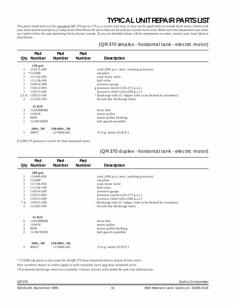
TYPICAL UNIT REPTYPICAL UNIT REPTYPICAL UNIT REPTYPICAL UNIT REPTYPICAL UNIT REPAIR PAIR PAIR PAIR PAIR PARARARARARTS LISTTS LISTTS LISTTS LISTTS LIST
(QR 370 simplex - horizontal tank - electric motor)
120 gal.1 113271-200 tank (200 p.s.i. max. working pressure)1 113280 top plate1 111136-050 tank drain valve1 111136-100 ball valve1 110514-300 pressure gauge1 110512-003 pressure switch (135-175 p.s.i.)1 110513-200 pressure relief valve (200 p.s.i.)
3.5 ft. 110515-100 discharge tube (1" copper tube to be formed by customer)2 111265-100 ferrule (for discharge tube)
15 H.P.3 110258B086 drive belt1 110476 motor pulley1 8936 motor pulley bushing1 111967K003 belt guard assembly
200v, 3Ø 230/460v, 3Ø1 40657 127466L042 15 h.p. motor (O.D.P.)
PartPartPartPartPart PartPartPartPartPart PartPartPartPartPartQtyQtyQtyQtyQty NumberNumberNumberNumberNumber NumberNumberNumberNumberNumber NumberNumberNumberNumberNumber DescriptionDescriptionDescriptionDescriptionDescription
!
The parts listed here are for standard QR 370 (up to 175 p.s.i.) units and may or may not be applicable to custom built units. Check withyour local authorized Quincy Compressor Distributor for parts that can be used for custom built units. Make sure the components you orderare rated within the safe operating limits of your system. If you are doubtful about which components to order, contact your local Quincydistributor.
*
PartPartPartPartPart PartPartPartPartPart PartPartPartPartPartQtyQtyQtyQtyQty NumberNumberNumberNumberNumber NumberNumberNumberNumberNumber NumberNumberNumberNumberNumber DescriptionDescriptionDescriptionDescriptionDescription
200 gal.1 113469-200 tank (200 p.s.i. max. working pressure)2 113280 top plate1 111136-050 tank drain valve1 111136-100 ball valve1 110514-300 pressure gauge2 110512-003 pressure switch (135-175 p.s.i.)1 110513-200 pressure relief valve (200 p.s.i.)
7 ft. 110515-100 discharge tube (1" copper tube to be formed by customer)2 111265-100 ferrule (for discharge tube)
15 H.P.6 110258B086 drive belt2 110476 motor pulley2 8936 motor pulley bushing2 111967K003 belt guard assembly
200v, 3Ø 230/460v, 3Ø2 40657 127466L042 15 h.p. motor (O.D.P.)
(QR 370 duplex - horizontal tank - electric motor)
!
* 113280 top plate is also used for all QR 370 base mounted electric motor driven units.Part numbers shown in italics apply to tank mounted units and base mounted units.! Pre-formed discharge tubes are available. Contact factory with model & tank size information.
§ 2298-175 pressure switch for base mounted units.
§

Quincy Service is always near.There are authorized QuincyDistributors located throughoutthe United States & Canada thatstock genuine Quincy parts &accessories for a wide range ofQuincy products.
Quincy Service specialists arefactory trained and will help keepyou in business. Call forAuthorized Quincy Service.
QuincyCompressor®
Reciprocating / Systems: 217.222.7700Air Master 217.277.0270E-mail: [email protected]: www.quincycompressor.com
www.quincyairmaster.com
T r u e B l u e R e l i a b i l i t y TM
Rotary / Vacuum / Systems: 334.937.5900Nearest Distributor: 888.424.7729
© 2002 Quincy CompressorAll Rights Reserved. Litho in U.S.A.