Embed Size (px)
Citation preview
T r u e B l u e R e l i a b i l i t y TM
This manual contains important safetyinformation and should be made availableto all personnel who operate and/ormaintain this product. Carefully read thismanual before attempting to operate orperform maintenance on this compressor.
Manual No. 52201-105 June 1999 Edition
Quincy QR-25® SeriesInstruction Manual
2 YEAR W2 YEAR W2 YEAR W2 YEAR W2 YEAR WARRARRARRARRARRANTANTANTANTANTY PROGRY PROGRY PROGRY PROGRY PROGRAMAMAMAMAMQuincy Compressor DivisionQuincy Compressor DivisionQuincy Compressor DivisionQuincy Compressor DivisionQuincy Compressor Division
Industrial Reciprocating ProductsIndustrial Reciprocating ProductsIndustrial Reciprocating ProductsIndustrial Reciprocating ProductsIndustrial Reciprocating Products
QR-25, QT & PLT SeriesQR-25, QT & PLT SeriesQR-25, QT & PLT SeriesQR-25, QT & PLT SeriesQR-25, QT & PLT Series
2-Stage Compressors2-Stage Compressors2-Stage Compressors2-Stage Compressors2-Stage Compressors
A two year warranty is available for new basic compressorsA two year warranty is available for new basic compressorsA two year warranty is available for new basic compressorsA two year warranty is available for new basic compressorsA two year warranty is available for new basic compressors
by purchasing a warranty maintenance kit. The warranty main-by purchasing a warranty maintenance kit. The warranty main-by purchasing a warranty maintenance kit. The warranty main-by purchasing a warranty maintenance kit. The warranty main-by purchasing a warranty maintenance kit. The warranty main-
tenance kit contains lubricant, filter(s) and registration infor-tenance kit contains lubricant, filter(s) and registration infor-tenance kit contains lubricant, filter(s) and registration infor-tenance kit contains lubricant, filter(s) and registration infor-tenance kit contains lubricant, filter(s) and registration infor-
mation for two years. (Kits may be purchased from the samemation for two years. (Kits may be purchased from the samemation for two years. (Kits may be purchased from the samemation for two years. (Kits may be purchased from the samemation for two years. (Kits may be purchased from the same
place you bought your compressor.)place you bought your compressor.)place you bought your compressor.)place you bought your compressor.)place you bought your compressor.)
Your basic compressor will have the same coverage for theYour basic compressor will have the same coverage for theYour basic compressor will have the same coverage for theYour basic compressor will have the same coverage for theYour basic compressor will have the same coverage for the
second year as it had for the first. You simply follow the recom-second year as it had for the first. You simply follow the recom-second year as it had for the first. You simply follow the recom-second year as it had for the first. You simply follow the recom-second year as it had for the first. You simply follow the recom-
mended maintenance spelled out in the instruction manual. Themended maintenance spelled out in the instruction manual. Themended maintenance spelled out in the instruction manual. Themended maintenance spelled out in the instruction manual. Themended maintenance spelled out in the instruction manual. The
two year warranty only applies when the maintenance kit istwo year warranty only applies when the maintenance kit istwo year warranty only applies when the maintenance kit istwo year warranty only applies when the maintenance kit istwo year warranty only applies when the maintenance kit is
purchased and registered within thirty days of compressorpurchased and registered within thirty days of compressorpurchased and registered within thirty days of compressorpurchased and registered within thirty days of compressorpurchased and registered within thirty days of compressor
purchase.purchase.purchase.purchase.purchase.
NOTE:NOTE:NOTE:NOTE:NOTE: The 2-year warranty program is The 2-year warranty program is The 2-year warranty program is The 2-year warranty program is The 2-year warranty program is notnotnotnotnot available for available for available for available for available for
remanufactured compressors.remanufactured compressors.remanufactured compressors.remanufactured compressors.remanufactured compressors.
QR-25 Series Quincy Compressor
52201-105, June 1999 i 3501 Wismann Lane, Quincy IL - 62305-3116
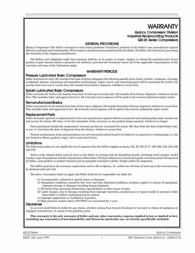
WWWWWARRANTYARRANTYARRANTYARRANTYARRANTYQuincy Compressor DivisionQuincy Compressor DivisionQuincy Compressor DivisionQuincy Compressor DivisionQuincy Compressor Division
Industrial Reciprocating ProductsIndustrial Reciprocating ProductsIndustrial Reciprocating ProductsIndustrial Reciprocating ProductsIndustrial Reciprocating ProductsQR-25 Series CompressorsQR-25 Series CompressorsQR-25 Series CompressorsQR-25 Series CompressorsQR-25 Series Compressors
GENERAL PROVISIONSGENERAL PROVISIONSGENERAL PROVISIONSGENERAL PROVISIONSGENERAL PROVISIONSQuincy Compressor (The Seller) warrants to each retail purchaser (Purchaser) products of the Seller's own manufacture againstdefects in material and workmanship. With respect to products not manufactured by the Seller, the Seller will, if practical, pass alongthe warranty of the original manufacturer.
The Seller's sole obligation under this warranty shall be, at its option, to repair, replace, or refund the purchase price of anyproduct or part thereof which is deemed to be defective, provided the Purchaser meets all of the applicable requirements of thiswarranty and none of the limitations apply.
WARRANTY PERIODSWARRANTY PERIODSWARRANTY PERIODSWARRANTY PERIODSWARRANTY PERIODSPressure Lubricated Basic CompressorsPressure Lubricated Basic CompressorsPressure Lubricated Basic CompressorsPressure Lubricated Basic CompressorsPressure Lubricated Basic CompressorsSeller warrants for sixty (60) months from date of factory shipment the following specific parts: head, cylinder, crankcase, oil pump,crankshaft, pistons, connecting rod assemblies and bearings. Labor, travel, and remaining parts will be warranted for twelve (12)months from start-up or twenty-four (24) months from factory shipment, whichever occurs first.
Splash Lubricated Basic CompressorsSplash Lubricated Basic CompressorsSplash Lubricated Basic CompressorsSplash Lubricated Basic CompressorsSplash Lubricated Basic CompressorsSeller warrants for twelve (12) months from date of start-up or twenty-four (24) months from factory shipment, whichever occursfirst. This includes labor and approved travel. All warranty travel expense will be paid to the nearest authorized repair center.
Remanufactured BasicsRemanufactured BasicsRemanufactured BasicsRemanufactured BasicsRemanufactured BasicsSeller warrants for six (6) months from date of start-up or eighteen (18) months from date of factory shipment, whichever occurs first.This includes labor and approved travel. All warranty travel expense will be paid to the nearest authorized repair center.
Replacement PartsReplacement PartsReplacement PartsReplacement PartsReplacement PartsSeller warrants repaired or replaced parts of its own manufacture against defects in material and workmanship under normal useand service for ninety (90) days, or for the remainder of the warranty on the product being repaired, whichever is longer.
Parts purchased outside the compressor's warranty period are warranted for ninety (90) days from the date of distributor sale,or one (1) year from the date of shipment from the factory, whichever occurs first.
Normal maintenance items and procedures are not warranted unless found to be defective in material or workmanship, i.e. butnot limited to filters, gaskets, rings, valves and control lines.
LimitationsLimitationsLimitationsLimitationsLimitationsThe following models are not eligible for travel expense when the Seller supplies as basics: X2, X3, X8, R-17, 108, 206, 210, 216, 240and 310.
Notice of the alleged defect must be given to the Seller in writing with all identifying details, including serial number, modelnumber, type of equipment and date of purchase within thirty (30) days of discovery of same during the warranty period. If requestedby Seller, such product or product thereof must be promptly returned to Seller, freight collect for inspection.
The Seller must have the warranty registration card on file at Quincy, IL. within ten (10) days of start-up or the warranty maybe declared null and void.
The above warranties shall not apply and Seller shall not be responsible nor liable for:
(a) Consequential, collateral or special losses or damages.(b) Equipment conditions caused by fair wear and tear, abnormal conditions, accident, neglect or misuse of equipment,
improper storage or damages resulting during shipment.(c) Deviation from operating instructions, specifications or other terms of sales.(d) Labor charges, loss or damage resulting from improper operation, maintenance or repairs made by person(s) other
than Seller or Seller's authorized service station.(e) Improper application or installation of product.(f) High pressure models (above 250 PSIG) are warranted for 1 year.
DisclaimerDisclaimerDisclaimerDisclaimerDisclaimerIn no event shall Seller be liable for any claims, whether arising from breach of contract or warranty or claims of negligence or
negligent manufacture, in excess of the purchase price.
This warranty is the sole warranty of Seller and any other warranties, express, implied in law or implied in fact,including any warranties of merchantability and fitness for particular use, are hereby specifically excluded.
QR-25 Series Quincy Compressor
52201-105, June 1999 ii 3501 Wismann Lane, Quincy IL - 62305-3116
ContentsSECTION 1SECTION 1SECTION 1SECTION 1SECTION 1 SAFETYSAFETYSAFETYSAFETYSAFETY
Safety First ............................................................................................................................................. 1Summary of Changes .............................................................................................................................. 3
SECTION 2SECTION 2SECTION 2SECTION 2SECTION 2 SYSTEM DYNAMICSSYSTEM DYNAMICSSYSTEM DYNAMICSSYSTEM DYNAMICSSYSTEM DYNAMICSDescription & Application.....................................................................................................................4Principles of Compression Cycles ........................................................................................................4Principles of Lubrication Systems .......................................................................................................5Principles of Cooling Systems ..............................................................................................................5Principles of Dryers & Filters ..............................................................................................................5Control Components ..............................................................................................................................6Control Versions ....................................................................................................................................6Specifications .........................................................................................................................................7
SECTION 3SECTION 3SECTION 3SECTION 3SECTION 3 INSTALLATIONINSTALLATIONINSTALLATIONINSTALLATIONINSTALLATIONReceiving Delivery .................................................................................................................................8Freight Damage .....................................................................................................................................8Location ..................................................................................................................................................9Electrical Supply Requirements ......................................................................................................... 10Mounting ............................................................................................................................................... 10System Components ............................................................................................................................. 11Wiring Schematics ................................................................................................................................ 12Induction System .................................................................................................................................. 14Compressed Air Discharge System ...................................................................................................... 15
SECTION 4SECTION 4SECTION 4SECTION 4SECTION 4 STSTSTSTSTARARARARART-UP & OPERAT-UP & OPERAT-UP & OPERAT-UP & OPERAT-UP & OPERATIONTIONTIONTIONTIONPre-Starting Checklist .......................................................................................................................... 18Initial Starting & Operating ................................................................................................................. 19Daily Starting Checklist ....................................................................................................................... 20
SECTION 5SECTION 5SECTION 5SECTION 5SECTION 5 MAINTENANCE & LUBRICATIONMAINTENANCE & LUBRICATIONMAINTENANCE & LUBRICATIONMAINTENANCE & LUBRICATIONMAINTENANCE & LUBRICATIONStopping for Maintenance ..................................................................................................................... 21Maintenance Schedule .......................................................................................................................... 21Maintenance Schedule Checklist Sample ............................................................................................ 21Lubrication ............................................................................................................................................ 22Pulley / Sheave Alignment & Belt Tension ......................................................................................... 23Pressure Switch Adjustment ................................................................................................................ 25Reversal of Compressor Rotation ......................................................................................................... 26Torque Specifications ............................................................................................................................ 27
SECTION 6SECTION 6SECTION 6SECTION 6SECTION 6 TROUBLESHOOTINGTROUBLESHOOTINGTROUBLESHOOTINGTROUBLESHOOTINGTROUBLESHOOTINGTroubleshooting .................................................................................................................................... 28
SECTION 7SECTION 7SECTION 7SECTION 7SECTION 7 REFERENCE INFORMATIONREFERENCE INFORMATIONREFERENCE INFORMATIONREFERENCE INFORMATIONREFERENCE INFORMATIONApproximate Capacity Correction for Altitude..................................................................................... 32Average Intercooler Pressures ............................................................................................................. 33Decal Locations ..................................................................................................................................... 34
QR-25 Series Quincy Compressor
52201-105, June 1999 1 3501 Wismann Lane, Quincy IL - 62305-3116
SECTION 1SECTION 1SECTION 1SECTION 1SECTION 1 SAFETYSAFETYSAFETYSAFETYSAFETY
Safety First
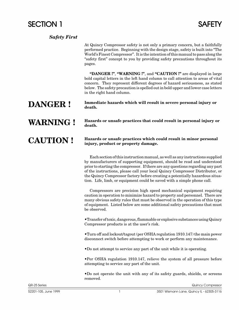
At Quincy Compressor safety is not only a primary concern, but a faithfullyperformed practice. Beginning with the design stage, safety is built into “TheWorld’s Finest Compressor”. It is the intention of this manual to pass along the“safety first” concept to you by providing safety precautions throughout itspages.
“DANGER !”, “WARNING !”, and “CAUTION !” are displayed in largebold capital letters in the left hand column to call attention to areas of vitalconcern. They represent different degrees of hazard seriousness, as statedbelow. The safety precaution is spelled out in bold upper and lower case lettersin the right hand column.
Immediate hazards which will result in severe personal injury ordeath.
Hazards or unsafe practices that could result in personal injury ordeath.
Hazards or unsafe practices which could result in minor personalinjury, product or property damage.
Each section of this instruction manual, as well as any instructions suppliedby manufacturers of supporting equipment, should be read and understoodprior to starting the compressor. If there are any questions regarding any partof the instructions, please call your local Quincy Compressor Distributor, orthe Quincy Compressor factory before creating a potentially hazardous situa-tion. Life, limb, or equipment could be saved with a simple phone call.
Compressors are precision high speed mechanical equipment requiringcaution in operation to minimize hazard to property and personnel. There aremany obvious safety rules that must be observed in the operation of this typeof equipment. Listed below are some additional safety precautions that mustbe observed.
•Transfer of toxic, dangerous, flammable or explosive substances using QuincyCompressor products is at the user’s risk.
•Turn off and lockout/tagout (per OSHA regulation 1910.147) the main powerdisconnect switch before attempting to work or perform any maintenance.
•Do not attempt to service any part of the unit while it is operating.
•Per OSHA regulation 1910.147, relieve the system of all pressure beforeattempting to service any part of the unit.
•Do not operate the unit with any of its safety guards, shields, or screensremoved.
WARNING !
CAUTION !
DANGER !
QR-25 Series Quincy Compressor
52201-105, June 1999 2 3501 Wismann Lane, Quincy IL - 62305-3116
•Do not remove or paint over any DANGER!, WARNING!, CAUTION!, orinstructional materials attached to the compressor. Lack of informationregarding hazardous conditions can cause property damage or personal injury.
•Periodically check all pressure relief valves for proper operation.
•Do not rebuild or change the pressure setting of the pressure relief valve,restrict the function of the inlet or outlet of the pressure relief valve, or replacethe pressure relief valve with a plug or any device not specifically certified forthis function.
•Do not install a shutoff valve in the compressor discharge line without firstinstalling a pressure relief valve of proper size and design between the shutoffvalve and the compressor.
•Do not use plastic pipe, rubber hose, or lead-tin soldered joints in any part ofthe compressed air system.
•Alterations must not be made to this compressor without Quincy Compressor’sapproval.
•Be sure that all tools, shipping and installation debris have been removedfrom the compressor and installation site prior to starting the compressor.
Do not operate a Quincy Compressor in excess of 250 PSIG unless ithas been tested and certified for high pressure application byQuincy Compressor prior to shipment.
•High pressure units (pressures exceeding 250 PSIG) require parts certifiedfor use in high pressure applications. When replacing parts on high pressureunits, please consult the parts manual and use only the part numbers listed inthat manual.
•Do not operate the compressor in excess of the ASME pressure vessel ratingfor the receiver or the service rating of the compressor, whichever is lower.
•Make a general overall inspection of the unit daily and correct any unsafesituations.
•Reckless behaviour of any kind involving compressed air is dangerous andcan cause very serious injury to the participants.
•Provisions should be made to have the instruction manual readily availableto the operator and maintenance personnel. If for any reason any part of themanual becomes illegible or the manual is lost, have it replaced immediately.The instruction manual should be read periodically to refresh one’s memory.It may prevent a serious or fatal accident.
•Never use a flammable or toxic solvent for cleaning the air filter or any parts.
WARNING !
QR-25 Series Quincy Compressor
52201-105, June 1999 3 3501 Wismann Lane, Quincy IL - 62305-3116
Air used for breathing or food processing must meet OSHA 29 CFR1910.134 or FDA 21 CFR 178.3570 regulations. Failure to do so maycause severe injury or death.
The owner, lessor or operator of any compressor unit manufactured byQuincy Compressor is hereby warned that failure to observe the above safetyprecautions may result in serious injury to personnel and/or damage toproperty.
Quincy Compressor neither states as fact, nor in any way implies that theabove list of safety precautions is an all inclusive list, the observance of whichwill prevent all damage to property or injury to personnel.
Every effort has been taken to ensure that complete and correct instructionshave been included in this manual. However, possible product updates andchanges may have occurred since this printing. Quincy Compressor reservesthe right to change specifications without incurring any obligation for equip-ment previously or subsequently sold.
Summary of Changes to This Manual(since previous printing dated February 1994):
· Added Maintenance Schedule Checklist.
· Added wiring schematics.
DANGER !
QR-25 Series Quincy Compressor
52201-105, June 1999 4 3501 Wismann Lane, Quincy IL - 62305-3116
SECTION 2SECTION 2SECTION 2SECTION 2SECTION 2 SYSTEM DYNAMICSSYSTEM DYNAMICSSYSTEM DYNAMICSSYSTEM DYNAMICSSYSTEM DYNAMICS
Description & Applica-tion
The Quincy Compressor QR-25Series consists of heavy dutyindustrial, belt driven, single ortwo stage compressors. Singlestage compressors are capableof delivering up to 100 PSIG con-tinuously. Some single stagecompressors are capable of de-livering up to 150 PSIGintermittantly (with proper con-trols and modifications). Twostage compressors can deliverup to 200 PSIG continuously,and up to 250, 350 or 500 PSIGintermittently depending uponthe model, controls and configu-ration.
Principles of Compres-sion Cycles
Single Stage Compressors
During the downstroke of a singlestage compressor, air is drawnthrough an intake valve in thehead of the compressor and intothe cylinder. At the bottom ofthe stroke, the intake valve closesand air is trapped in the cylin-
der. The air is then compressed in the cylinder during the upstroke of thepiston. Total compression, from atmospheric pressure to the final dischargepressure, is accomplished in one stroke of the piston.
Two Stage Compressors
During the downstroke of the piston of a two stage compressor, air is drawnthrough an intake valve in the head of the compressor into the low pressurecylinder and compressed during the upstroke of the piston.
The compressed air is then released through a discharge valve in the headof the compressor to an intercooler (usually finned tubing) where the heatresulting from compression is allowed to dissipate. The cooler compressed airis then drawn into a second compression cylinder, the high pressure cylinder,for compression to final pressure.
From there the compressed air is released through a discharge valve to anair receiver tank or directly to a network of compressed air supply lines. In onerevolution of the crankshaft a compression cycle is completed.
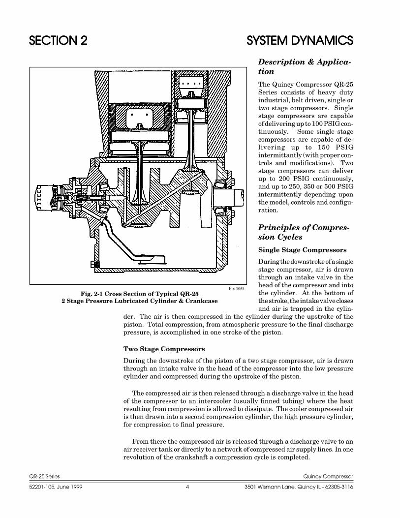
Pix 1064Fig. 2-1 Cross Section of Typical QR-25
2 Stage Pressure Lubricated Cylinder & Crankcase
QR-25 Series Quincy Compressor
52201-105, June 1999 5 3501 Wismann Lane, Quincy IL - 62305-3116
Principles of Lubrication Systems
Splash Lubricated Models
With each stroke of the compressor, a dipper attached to the bottom of theconnecting rod , dips into an oil bath at the bottom of the crankcase. This dippersplashes oil throughout the interior of the crankcase, lubricating all movingparts.
It is important with this system that the oil level be maintained between thehigh and low level marks on the dipstick. If the oil level is too high, excessiveoil carryover could result. If the oil level is too low, or the compressor is notoperated within the correct RPM range, the moving parts will not be ad-equately lubricated.
Pressure Lubricated Models
Moving parts within the crankcase are supplied with lubrication by a positivedisplacement, gerotor type oil pump. Oil is drawn up from the bottom of thecrankcase to the oil pump through an oil sump strainer screen. The oil is thenforced under pressure through the oil filter (if so equipped). Oil travels underpressure through drilled journals in the crankshaft and connecting rods tolubricate crankshaft bearings, wrist pin bearings and the cylinder walls.
Principles of Cooling Systems
Aircooled Models
Fan blades of the compressor sheave force ambient air across fins of thecylinder head(s), and intercooler fins of two stage compressors, to cool thecompressor. QR-25 series compressors are normally set up at the factory witha sheave that turns in a counterclockwise rotation. For special applications,clockwise rotation compressor sheaves are available as optional equipment onsome models. Due to standard drive motor limitations, it is recommended thatthe compressor be operated in temperatures under 104°F.
Watercooled Models
In addition to cooling action provided by the fan blades of the compressorsheave, cool water is circulated throughout an internal water jacket surround-ing the cylinders and heads of watercooled models.
Principles of Dryers & Filters
Moisture occurs naturally in air lines as a result of compression. Moisturevapor in ambient air is concentrated when pressurized and condenses whencooled in downstream air piping. Compressed air dryers reduce the moisturevapor concentration and prevent water formation in compressed air lines.Dryers are a recommended companion to filters, aftercoolers, and automaticdrains for improving the productivity of compressed air systems.
Water and moisture vapor removal increases the efficiency of air operatedequipment, reduces contamination and rusting, increases the service life ofpneumatic equipment and tools, prevents air line freeze-ups, and reducesproduct rejects.
QR-25 Series Quincy Compressor
52201-105, June 1999 6 3501 Wismann Lane, Quincy IL - 62305-3116
Control Components
Unloader Towers: Provided as part of the basic compressor when controlversion is specified.
Pilot Valve: Used in conjunction with unloader towers when the compressoris to run continuously and an operating pressure range is to be maintained.Refer to your parts manual for correct pilot valve, ranges and settings.
Hydraulic Unloader: Used on pressure lubricated compressors to protectthe compressor in the event of a potentially damaging oil pressure drop. Alsoensures that the compressor does not begin to produce compressed air untilthere is sufficient oil pressure.
Pressure Switch: Used for start/stop applications (usually accompanied bya hydraulic unloader). The pressure switch detects the demand for compressedair and allows the unit to start. When the demand is satisfied, the unit stops.
Control Versions
Various control versions are available for the model QR-25 series compres-sors. The control version required is determined by how frequent there isa demand for compressed air. The idea is to create compressed air ondemand, but to limit the number of times a motor must start the compressorin a given time period. To prevent motor burnout, the motor should belimited to no more than six (6) starts per hour.
Control Version P : Describes a basic compressor with no added controlfeatures.
Control Version L : Consists of unloader tower(s)* located on the head ofthe compressor, a hydraulic unloader mounted on the bearing carrier, anda pressure switch. This version is recommended for those applicationswhere the compressor will not be required to start more than six (6) times
per hour. A compressor equipped with control Version L is sometimes referredto as a “start/stop machine”
The pressure switch detects the demand for compressed air and allowsthe unit to start. When the demand is satisfied, the unit stops.
The hydraulic unloader allows the compressor to start in an “unloaded”state, that is, the compressor starts but does not begin to create compressedair until oil pressure is established. The hydraulic unloader also guardsagainst excessive damage in the event of an oil pressure drop.
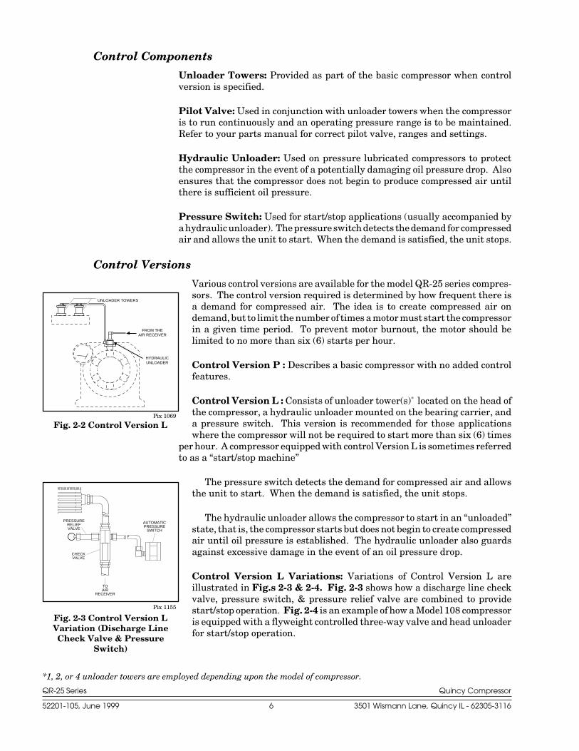
Control Version L Variations: Variations of Control Version L areillustrated in Fig.s 2-3 & 2-4. Fig. 2-3 shows how a discharge line checkvalve, pressure switch, & pressure relief valve are combined to providestart/stop operation. Fig. 2-4 is an example of how a Model 108 compressoris equipped with a flyweight controlled three-way valve and head unloaderfor start/stop operation.
FROM THEAIR RECEIVER
HYDRAULICUNLOADER
P
UNLOADER TOWERS
Fig. 2-2 Control Version LPix 1069
AUTOMATICPRESSURE
SWITCH
CHECKVALVE
TOAIR
RECEIVER
PRESSURERELIEFVALVE
Pix 1155
Fig. 2-3 Control Version LVariation (Discharge LineCheck Valve & Pressure
Switch)
*1, 2, or 4 unloader towers are employed depending upon the model of compressor.
QR-25 Series Quincy Compressor
52201-105, June 1999 7 3501 Wismann Lane, Quincy IL - 62305-3116
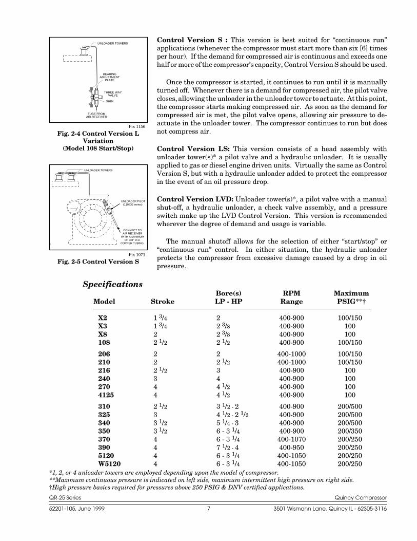
Control Version S : This version is best suited for “continuous run”applications (whenever the compressor must start more than six [6] timesper hour). If the demand for compressed air is continuous and exceeds onehalf or more of the compressor’s capacity, Control Version S should be used.
Once the compressor is started, it continues to run until it is manuallyturned off. Whenever there is a demand for compressed air, the pilot valvecloses, allowing the unloader in the unloader tower to actuate. At this point,the compressor starts making compressed air. As soon as the demand forcompressed air is met, the pilot valve opens, allowing air pressure to de-actuate in the unloader tower. The compressor continues to run but doesnot compress air.
Control Version LS: This version consists of a head assembly withunloader tower(s)* a pilot valve and a hydraulic unloader. It is usuallyapplied to gas or diesel engine driven units. Virtually the same as ControlVersion S, but with a hydraulic unloader added to protect the compressorin the event of an oil pressure drop.
Control Version LVD: Unloader tower(s)*, a pilot valve with a manualshut-off, a hydraulic unloader, a check valve assembly, and a pressureswitch make up the LVD Control Version. This version is recommendedwherever the degree of demand and usage is variable.
The manual shutoff allows for the selection of either “start/stop” or“continuous run” control. In either situation, the hydraulic unloaderprotects the compressor from excessive damage caused by a drop in oilpressure.
SpecificationsBore(s) RPM Maximum
Model Stroke LP - HP Range PSIG**†
X2 1 3/4 2 400-900 100/150X3 1 3/4 2 3/8 400-900 100X8 2 2 3/8 400-900 100108 2 1/2 2 1/2 400-900 100/150
206 2 2 400-1000 100/150210 2 2 1/2 400-1000 100/150216 2 1/2 3 400-900 100240 3 4 400-900 100270 4 4 1/2 400-900 1004125 4 4 1/2 400-900 100
310 2 1/2 3 1/2 - 2 400-900 200/500325 3 4 1/2 - 2 1/2 400-900 200/500340 3 1/2 5 1/4 - 3 400-900 200/500350 3 1/2 6 - 3 1/4 400-900 200/350370 4 6 - 3 1/4 400-1070 200/250390 4 7 1/2 - 4 400-950 200/2505120 4 6 - 3 1/4 400-1050 200/250W5120 4 6 - 3 1/4 400-1050 200/250
UNLOADER TOWERS
TUBE FROMAIR RECEIVER
SHIM
THREE WAYVALVE
BEARINGADJUSTMENT
PLATE
Pix 1156
Fig. 2-4 Control Version LVariation
(Model 108 Start/Stop)
UNLOADER TOWERS
UNLOADER PILOT(110832 series)
071
CONNECT TOAIR RECEIVER
WITH A MINIMUMOF 3/8" O.D.
COPPER TUBING.
Pix 1071
Fig. 2-5 Control Version S
*1, 2, or 4 unloader towers are employed depending upon the model of compressor.**Maximum continuous pressure is indicated on left side, maximum intermittent high pressure on right side.†High pressure basics required for pressures above 250 PSIG & DNV certified applications.
QR-25 Series Quincy Compressor
52201-105, June 1999 8 3501 Wismann Lane, Quincy IL - 62305-3116
SECTION 3SECTION 3SECTION 3SECTION 3SECTION 3 INSTINSTINSTINSTINSTALLAALLAALLAALLAALLATIONTIONTIONTIONTION
Receiving Delivery
Immediately upon receipt of compressor equipment and prior to completelyuncrating, the following steps should be taken:
Step 1) Inspect compressor equipment for damage that may have occurredduring shipment. If any damage is found, demand an inspectionfrom the carrier. Ask the carrier how to file a claim for shippingdamages. (Refer to SECTION 3, Freight Damage for completedetails.) Shipping damage is not covered by Quincy Com-pressor warranty.
Step 2) Insure that adequate lifting equipment is available for moving thecompressor equipment.
Improper lifting can result in component or system damage, orpersonal injury. Follow good shop practices and safety procedureswhen moving the unit.
Step 3) Read the compressor nameplate to verify the model and sizeordered.
Step 4) Read the motor nameplate to be sure the motor is compatible withyour electrical conditions (volts, phase, hertz).
Step 5) Read the pressure relief valve nameplate to be sure it does notexceed the working pressure shown on the compressor or any othercomponent in the system.
Step 6) Read and understand the safety precautions containedwithin this manual. The successful and efficient operation ofcompressor equipment depends largely upon the amount of caretaken to install and maintain the equipment. Quincy Compressorstrongly recommends that any or all person(s) in charge of install-ing, maintaining, or servicing one of our compressors read andunderstand the entire contents of this manual in order to performsuch duties safely and efficiently.
Freight Damage
It is extremely important that you examine every carton and crate as soon asyou receive it. If there is any obvious damage to the shipping container, havethe delivering carrier sign the freight bill, noting the apparent damage, andrequest a damage report.
If concealed damage is discovered at a later date, the carrier mustbe notified within 15 days of initial receipt of freight. Concealedshipping damage is not covered by Quincy Compressor Warranty.Contact the carrier as soon as possible, giving them an opportunity to inspectthe shipment at the premises where the delivery was made. Do not move thedamaged freight from the premises where the original delivery was made.
CAUTION !
QR-25 Series Quincy Compressor
52201-105, June 1999 9 3501 Wismann Lane, Quincy IL - 62305-3116
Retain all containers and packing for inspection by the carrier.
A claim form can be requested from the carrier: Standard Form forPresentation of Loss and Damage Claims (form # 3208). Your claim will needto be substantiated with the following documents:
a.) form #3208
b.) original bill of lading
c.) original paid freight bill
d.) original invoice or certified copy
e.) other particulars obtainable in proof of loss or damage (photos,damage inspection, etc.)
The proper description and classification of our product in the NationalMotor Freight Classification 100-H, contained in item 118100, reads as follows:Compressors, air, or air ends: with or without air tanks, hose or nozzles,mounted or not mounted.”
We suggest that these instructions be circulated to your shipping andreceiving personnel.
Location
Quincy air compressors should be installed in an area that is clean, welllighted, and adequately ventilated. Inspection and maintenance checks arerequired daily. Therefore, sufficient space needs to be provided around thecompressor for safe and proper inspection, cleaning, and maintenance.
The compressor must not be installed closer than 24 inches to a wall oranother compressor. This allows ample circulation of air across the compres-sor cylinders, heads and cooler (if so equipped). If at all possible, the pulleydrive system (i.e. motor pulley, compressor sheave, belts and guard) should belocated next to a wall to minimize any danger created by the drive system whilethe compressor is operating.
Due to standard drive motor limitations, it is recommended that thecompressor be operated in temperatures under 104°F. In cold climates, thecompressor should be installed in a heated building.
Do not operate this compressor in ambient temperatures lowerthan -15° F. A crankcase heater is recommended for a compressorthat is to operate in temperatures under 32° F.
Under no circumstances should a compressor be used in an areathat may be exposed to toxic, volatile, or corrosive atmosphere.Do not store toxic, volatile, or corrosive agents near the compres-sor.
Noise
Noise is a potential health hazard that must be considered. There are federaland local laws governing acceptable noise levels. Check with local officials forspecifications.
CAUTION !
WARNING !
QR-25 Series Quincy Compressor
52201-105, June 1999 10 3501 Wismann Lane, Quincy IL - 62305-3116
Excessive noise can be effectively reduced through various methods. Totalenclosures, intake silencers, baffle walls, relocating or isolating the compres-sor can reduce noise levels. Care must be taken when constructing totalenclosures or baffle walls. If not properly constructed or positioned, they couldcontribute to unacceptable noise levels or overheating. Consult your localQuincy Compressor Distributor if assistance is required.
Unusual noise or vibration indicates a problem. Do not operate thecompressor until the source has been identified and corrected.
Electrical Supply Requirements
The electrical installation of this unit should be performed by a qualifiedelectrician with knowledge of the National Electrical Code (NEC), OSHA codeand/or any local or state codes having precedence.
Before installation, the electrical supply should be checked for adequatewire size and transformer capacity. A suitable circuit breaker or fuseddisconnect switch should be provided. When a 3 phase motor is used to drivea compressor, any unreasonable voltage imbalance between the legs must beeliminated and any low voltage corrected to prevent excessive current draw.Note: This unit must be grounded.
The installation, electric motor, wiring, and all electrical controls must bein accordance with NFPA 70 National Electric Code, National Electric SafetyCode, state and local codes. Failure to abide by the national, state and localcodes may result in physical harm and/or property damage.
High voltage may cause personal injury or death. Disconnect andlockout/tagout per OSHA regulation 1910.147 all electrical powersupplies before opening the electrical enclosure or servicing.
Never assume a compressor is safe to work on just because it is notoperating. It could restart at any time. Follow all safety precau-tions outlined in SECTION 5, Stopping For Maintenance.
NEMA electrical enclosures and components must be appropriateto the area installed.
Mounting
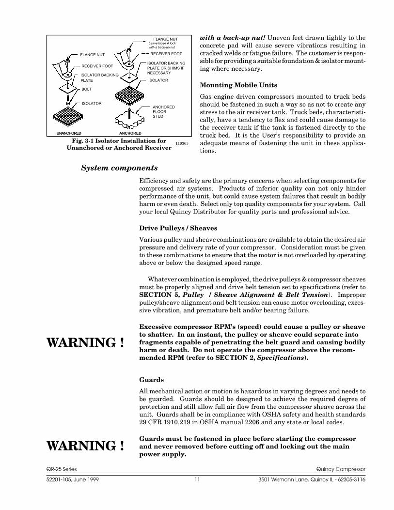
Proper mounting of Quincy compressor units is crucial to the safe operationand longevity of the equipment. The installation requires a flat and levelconcrete floor or pad (for mobile units see Mounting Mobile Units). Satisfac-tory results can usually be obtained by mounting the compressor unit onvibration isolating pads available from your local Quincy Distributor. Allvertical tank units must be anchored! Refer to Fig. 3-1, Isolator Instal-lation for Unanchored or Anchored Receiver.
State or local codes may mandate that the compressor be bolted to the floor.In this case the unit must be leveled and bolted making absolutely certain thefeet are not stressed in any manner. Leave the flange nut loose & lock it
CAUTION !
DANGER !
WARNING !
CAUTION !
QR-25 Series Quincy Compressor
52201-105, June 1999 11 3501 Wismann Lane, Quincy IL - 62305-3116
110365Fig. 3-1 Isolator Installation forUnanchored or Anchored Receiver
FLANGE NUT
RECEIVER FOOT
ISOLATOR BACKINGPLATE
BOLT
ISOLATOR
FLANGE NUT
Leave loose & lockwith a back-up nut
RECEIVER FOOT
ISOLATOR BACKINGPLATE OR SHIMS IFNECESSARY
ISOLATOR
ANCHOREDFLOORSTUD
UNANCHORED ANCHORED
with a back-up nut! Uneven feet drawn tightly to theconcrete pad will cause severe vibrations resulting incracked welds or fatigue failure. The customer is respon-sible for providing a suitable foundation & isolator mount-ing where necessary.
Mounting Mobile Units
Gas engine driven compressors mounted to truck bedsshould be fastened in such a way so as not to create anystress to the air receiver tank. Truck beds, characteristi-cally, have a tendency to flex and could cause damage tothe receiver tank if the tank is fastened directly to thetruck bed. It is the User’s responsibility to provide anadequate means of fastening the unit in these applica-tions.
System components
Efficiency and safety are the primary concerns when selecting components forcompressed air systems. Products of inferior quality can not only hinderperformance of the unit, but could cause system failures that result in bodilyharm or even death. Select only top quality components for your system. Callyour local Quincy Distributor for quality parts and professional advice.
Drive Pulleys / Sheaves
Various pulley and sheave combinations are available to obtain the desired airpressure and delivery rate of your compressor. Consideration must be givento these combinations to ensure that the motor is not overloaded by operatingabove or below the designed speed range.
Whatever combination is employed, the drive pulleys & compressor sheavesmust be properly aligned and drive belt tension set to specifications (refer toSECTION 5, Pulley / Sheave Alignment & Belt Tension). Improperpulley/sheave alignment and belt tension can cause motor overloading, exces-sive vibration, and premature belt and/or bearing failure.
Excessive compressor RPM’s (speed) could cause a pulley or sheaveto shatter. In an instant, the pulley or sheave could separate intofragments capable of penetrating the belt guard and causing bodilyharm or death. Do not operate the compressor above the recom-mended RPM (refer to SECTION 2, Specifications).
Guards
All mechanical action or motion is hazardous in varying degrees and needs tobe guarded. Guards should be designed to achieve the required degree ofprotection and still allow full air flow from the compressor sheave across theunit. Guards shall be in compliance with OSHA safety and health standards29 CFR 1910.219 in OSHA manual 2206 and any state or local codes.
Guards must be fastened in place before starting the compressorand never removed before cutting off and locking out the mainpower supply.
WARNING !
WARNING !
QR-25 Series Quincy Compressor
52201-105, June 1999 12 3501 Wismann Lane, Quincy IL - 62305-3116
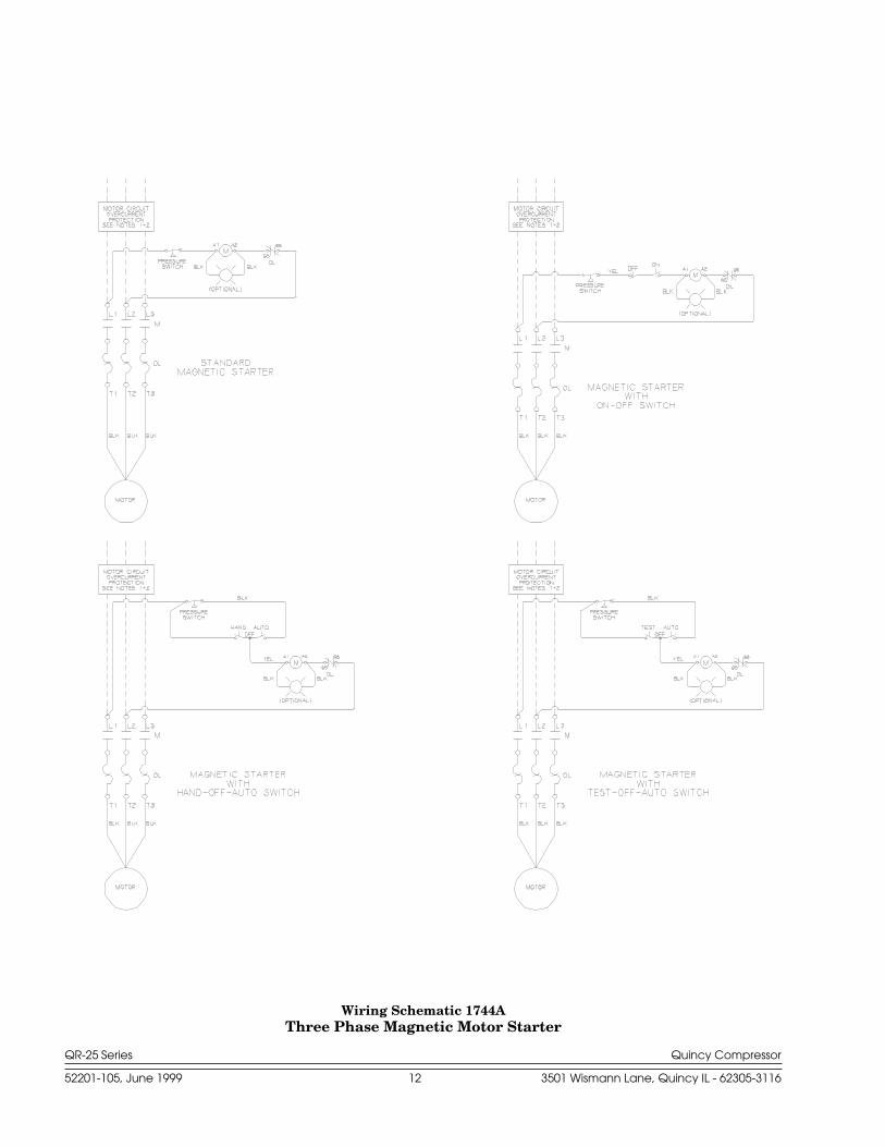
Wiring Schematic 1744AThree Phase Magnetic Motor Starter
QR-25 Series Quincy Compressor
52201-105, June 1999 13 3501 Wismann Lane, Quincy IL - 62305-3116
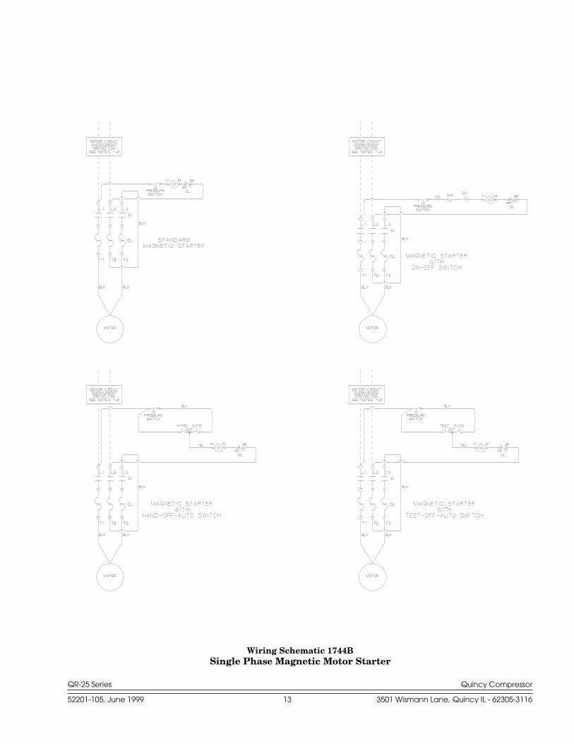
Wiring Schematic 1744BSingle Phase Magnetic Motor Starter
QR-25 Series Quincy Compressor
52201-105, June 1999 14 3501 Wismann Lane, Quincy IL - 62305-3116
DANGER !
Check Valves
Check valves are designed to prevent back-flow of air pressure in the com-pressed air system (air flows freely in one direction only). The check valve mustbe properly sized for air flow and temperature. Do not rely upon a checkvalve to isolate a compressor from a pressurized tank or compressedair delivery system during maintenance procedures!
Manual Shutoff Valves
Manual shutoff valves block the flow of air pressure in either direction. Thistype of valve can be used to isolate a compressor from a pressurized system,provided the system is equipped with a pressure relief valve capable of beingmanually released. The pressure relief valve should be installed between themanual shutoff valve and the compressor (refer to Fig. 3-2, Typical Drop Leg& Component Location).
Pressure Relief Valves
Pressure relief valves aid in preventing system failures by relieving systempressure when compressed air reaches a determined level. They are availablein various pressure settings to accommodate a range of applications. Pressurerelief valves are preset by the manufacturer and under no circumstancesshould the setting be changed by anyone other than the manufacturer.
Pressure relief valves are designed to protect compressed airsystems in accordance with ASME B19 safety standards. Failure toprovide properly sized pressure relief valves may cause propertydamage, severe personal injury or even death.
Induction System
Air Intake
A clean, cool and dry air supply is essential to the satisfactory operation of yourQuincy air compressor. The standard air filter that the compressor is equippedwith when leaving the factory is of sufficient size and design to meet normalconditions, when properly serviced, in accordance with the maintenancesection of this manual.
If, however, the compressor is to be installed in a location where consider-able dust, dirt and other contaminants are prevalent, consult your local QuincyDistributor for advice and optional filters. It is the user’s responsibility toprovide adequate filtration for those conditions. Oil bath filters are not to beused. Warranty will be void if a failure is determined to be caused byinadequate filtration.
Remote Inlet Filters
Depending on the size of the compressor and the size and construction of theroom in which the unit operates, the air inlet may have to be located outsideof the room. If it is necessary to remotely install the air filter, make the inletpiping as short and direct as possible. Remotely installed air filters can leadto vibrations in the inlet piping. These vibrations can be minimized by addinga pulsation dampener in the inlet piping between the remote inlet filter(s) andthe compressor.
QR-25 Series Quincy Compressor
52201-105, June 1999 15 3501 Wismann Lane, Quincy IL - 62305-3116
If the intake is piped to outside atmosphere, a hooded filter should beinstalled to prevent water or snow from being ingested into the compressor.
All inlet piping should be at least the same size (or larger) in diameter as theinlet connection to the compressor. For every 10 feet of inlet piping or every90° bend, increase the inlet piping diameter by one pipe size. The inlet pipingmust be thoroughly clean inside. Remove all weld slag, rust or dirt. Galvanizedpipe with threaded or flanged fittings is preferred.
Never locate the compressor air inlet system where toxic, volatileor corrosive vapors, air temperatures exceeding 100°F, water, orextremely dirty air could be ingested. These types of atmospherescould adversely affect the performance of the compressor system.
Compressed Air Discharge System
The discharge piping should be of the same diameter as the compressordischarge connection, or sized so that the pressure drop at any point in thesystem does not exceed 10% of the air receiver pressure. Install auxiliary airreceivers near heavy loads or at the far end of a long system. This will insuresufficient pressure if the use is intermittent, or sudden large demands areplaced on the system.
Discharge piping should slope to a drop leg (refer to Fig. 3-2, Typical DropLeg & Component Location) or moisture trap to provide a collection pointwhere moisture can be easily removed. All service line outlets should beinstalled above the moisture traps to prevent moisture from entering the toolor device using the air. Manual shutoff valves, protected by pressure reliefvalves, should be installed at all service line outlets to eliminate leakage whilethe tools are not in use.
As with any piping, all parts of the discharge piping should fit so as not tocreate any stress between the piping and components.
Pnuematic Circuit Breakers or Velocity Fuses
The Occupational Safety and Health Act (OSHA), Section 1926.303, Para-graph 7, published in the Code of Federal Regulations 29 CFR 1920.1, revisedJuly 1, 1982 states that all hoses exceeding 1/2" inside diameter shall have asafety device at the source of supply or branch line to reduce pressure in caseof a hose failure”
These pnuematic safety devices are designed to prevent hoses from whip-ping and/or the loss of hazardous or toxic gasses, all of which could result in aserious or fatal accident.
Never join pipes or fittings with lead-tin soldering. Welded orthreaded steel pipes and cast iron fittings, designed for the pres-sures and temperatures, are recommended.
CAUTION !
WARNING !
QR-25 Series Quincy Compressor
52201-105, June 1999 16 3501 Wismann Lane, Quincy IL - 62305-3116
Pressure Vessels
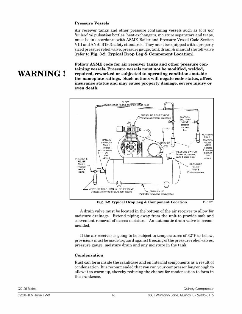
Air receiver tanks and other pressure containing vessels such as (but notlimited to) pulsation bottles, heat exchangers, moisture separators and traps,must be in accordance with ASME Boiler and Pressure Vessel Code SectionVIII and ANSI B19.3 safety standards. They must be equipped with a properlysized pressure relief valve, pressure gauge, tank drain, & manual shutoff valve(refer to Fig. 3-2, Typical Drop Leg & Component Location).
Follow ASME code for air receiver tanks and other pressure con-taining vessels. Pressure vessels must not be modified, welded,repaired, reworked or subjected to operating conditions outsidethe nameplate ratings. Such actions will negate code status, affectinsurance status and may cause property damage, severe injury oreven death.
A drain valve must be located in the bottom of the air receiver to allow formoisture drainage. Extend piping away from the unit to provide safe andconvenient removal of excess moisture. An automatic drain valve is recom-mended.
If the air receiver is going to be subject to temperatures of 32°F or below,provisions must be made to guard against freezing of the pressure relief valves,pressure gauge, moisture drain and any moisture in the tank.
Condensation
Rust can form inside the crankcase and on internal components as a result ofcondensation. It is recommended that you run your compressor long enough toallow it to warm up, thereby reducing the chance for condensation to form inthe crankcase.
Fig. 3-2 Typical Drop Leg & Component Location Pix 1007
WARNING !
QR-25 Series Quincy Compressor
52201-105, June 1999 17 3501 Wismann Lane, Quincy IL - 62305-3116
Condensation can also form in the air tank of your compressor. When thishappens, a mixture of air and moisture will be expelled through the servicevalve and into whatever is connected to the valve (e.g. air hoses, metal air lines,pneumatic tools, spray guns). An in-line filter or dryer, available from yourlocal Quincy distributor, may be required to eliminate the moisture.
Condensation in the air tank can be kept to a minimum by draining the tankon a daily basis. This also reduces the risk of rust developing and weakeningthe tank.
Manual Tank Drain Valve Operation
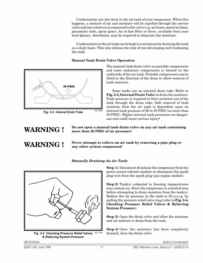
The manual tank drain valve on portable compressorsand some stationary compressors is located on theunderside of the air tank. Portable compressors can betilted in the direction of the drain to allow removal oftank moisture.
Some tanks use an internal drain tube (Refer toFig. 3-3, Internal Drain Tube) to drain the moisture.Tank pressure is required to force moisture out of thetank through the drain tube. Safe removal of tankmoisture from the air tank is dependent upon aninternal tank pressure of 20 to 30 PSIG (no more than30 PSIG). Higher internal tank pressures are danger-ous and could cause serious injury!
Do not open a manual tank drain valve on any air tank containingmore than 30 PSIG of air pressure!
Never attempt to relieve an air tank by removing a pipe plug orany other system component!
Manually Draining An Air Tank:
Step 1) Disconnect & lockout the compressor from thepower source (electric models) or disconnect the sparkplug wire from the spark plug (gas engine models).
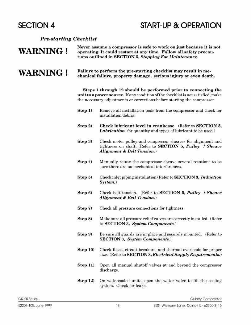
Step 2) Tank(s) subjected to freezing temperaturesmay contain ice. Store the compressor in a heated areabefore attempting to drain moisture from the tank(s).Reduce the air pressure in the tank to 30 p.s.i.g. bypulling the pressure relief valve ring (refer to Fig. 3-4,Checking Pressure Relief Valves & RelievingSystem Pressure).
Step 3) Open the drain valve and allow the moistureand air mixture to drain from the tank.
Step 4) Once the moisture has been completelydrained, close the drain valve.Pix 1160Fig. 3-4 Checking Pressure Relief Valves
& Relieving System Pressure
Pix 1224Fig. 3-3 Internal Drain Tube
30 PSIG
WARNING !
WARNING !
QR-25 Series Quincy Compressor
52201-105, June 1999 18 3501 Wismann Lane, Quincy IL - 62305-3116
SECTION 4SECTION 4SECTION 4SECTION 4SECTION 4 STSTSTSTSTARARARARART-UP & OPERAT-UP & OPERAT-UP & OPERAT-UP & OPERAT-UP & OPERATIONTIONTIONTIONTION
Pre-starting Checklist
Never assume a compressor is safe to work on just because it is notoperating. It could restart at any time. Follow all safety precau-tions outlined in SECTION 5, Stopping For Maintenance.
Failure to perform the pre-starting checklist may result in me-chanical failure, property damage , serious injury or even death.
Steps 1 through 12 should be performed prior to connecting theunit to a power source. If any condition of the checklist is not satisfied, makethe necessary adjustments or corrections before starting the compressor.
Step 1) Remove all installation tools from the compressor and check forinstallation debris.
Step 2) Check lubricant level in crankcase. (Refer to SECTION 5,Lubrication for quantity and types of lubricant to be used.)
Step 3) Check motor pulley and compressor sheaves for alignment andtightness on shaft. (Refer to SECTION 5, Pulley / SheaveAlignment & Belt Tension.)
Step 4) Manually rotate the compressor sheave several rotations to besure there are no mechanical interferences.
Step 5) Check inlet piping installation (Refer to SECTION 3, InductionSystem.)
Step 6) Check belt tension. (Refer to SECTION 5, Pulley / SheaveAlignment & Belt Tension.)
Step 7) Check all pressure connections for tightness.
Step 8) Make sure all pressure relief valves are correctly installed. (Referto SECTION 3, System Components.)
Step 9) Be sure all guards are in place and securely mounted. (Refer toSECTION 3, System Components.)
Step 10) Check fuses, circuit breakers, and thermal overloads for propersize. (Refer to SECTION 3, Electrical Supply Requirements.)
Step 11) Open all manual shutoff valves at and beyond the compressordischarge.
Step 12) On watercooled units, open the water valve to fill the coolingsystem. Check for leaks.
WARNING !
WARNING !
QR-25 Series Quincy Compressor
52201-105, June 1999 19 3501 Wismann Lane, Quincy IL - 62305-3116
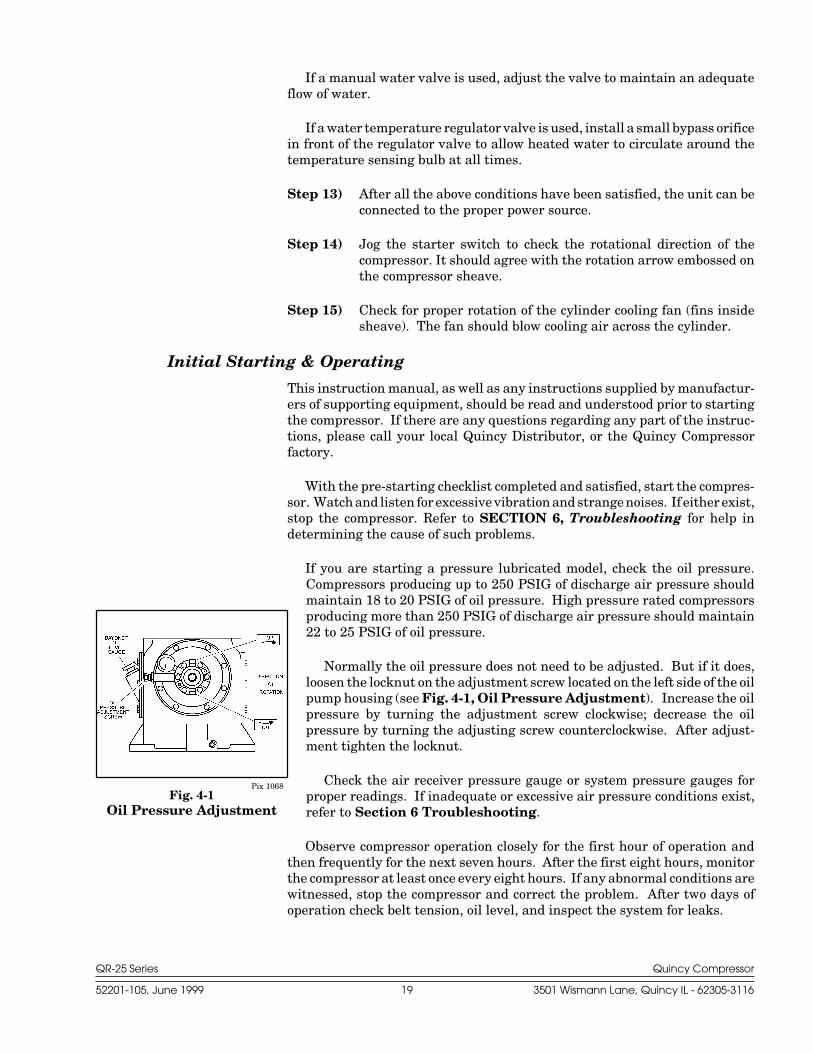
Pix 1068Fig. 4-1
Oil Pressure Adjustment
If a manual water valve is used, adjust the valve to maintain an adequateflow of water.
If a water temperature regulator valve is used, install a small bypass orificein front of the regulator valve to allow heated water to circulate around thetemperature sensing bulb at all times.
Step 13) After all the above conditions have been satisfied, the unit can beconnected to the proper power source.
Step 14) Jog the starter switch to check the rotational direction of thecompressor. It should agree with the rotation arrow embossed onthe compressor sheave.
Step 15) Check for proper rotation of the cylinder cooling fan (fins insidesheave). The fan should blow cooling air across the cylinder.
Initial Starting & Operating
This instruction manual, as well as any instructions supplied by manufactur-ers of supporting equipment, should be read and understood prior to startingthe compressor. If there are any questions regarding any part of the instruc-tions, please call your local Quincy Distributor, or the Quincy Compressorfactory.
With the pre-starting checklist completed and satisfied, start the compres-sor. Watch and listen for excessive vibration and strange noises. If either exist,stop the compressor. Refer to SECTION 6, Troubleshooting for help indetermining the cause of such problems.
If you are starting a pressure lubricated model, check the oil pressure.Compressors producing up to 250 PSIG of discharge air pressure shouldmaintain 18 to 20 PSIG of oil pressure. High pressure rated compressorsproducing more than 250 PSIG of discharge air pressure should maintain22 to 25 PSIG of oil pressure.
Normally the oil pressure does not need to be adjusted. But if it does,loosen the locknut on the adjustment screw located on the left side of the oilpump housing (see Fig. 4-1, Oil Pressure Adjustment). Increase the oilpressure by turning the adjustment screw clockwise; decrease the oilpressure by turning the adjusting screw counterclockwise. After adjust-ment tighten the locknut.
Check the air receiver pressure gauge or system pressure gauges forproper readings. If inadequate or excessive air pressure conditions exist,refer to Section 6 Troubleshooting.
Observe compressor operation closely for the first hour of operation andthen frequently for the next seven hours. After the first eight hours, monitorthe compressor at least once every eight hours. If any abnormal conditions arewitnessed, stop the compressor and correct the problem. After two days ofoperation check belt tension, oil level, and inspect the system for leaks.
QR-25 Series Quincy Compressor
52201-105, June 1999 20 3501 Wismann Lane, Quincy IL - 62305-3116
Daily Starting Checklist
Do not proceed until the Pre-starting Checklist and Initial Starting &Operating sub-sections have been read and are thoroughly understood.
Step 1) Check oil level in crankcase.
Step 2) Drain liquid from the air receiver (refer to Section 3, ManuallyDraining An Air Tank) and moisture trap (if so equipped).
Step 3) Turn on cooling water (watercooled units)
Step 4) Jog the starter button and check compressor rotation. Note:Continuous Run Units - Prior to starting a continuous run unit,pull the ring attached to the pilot valve out and turn the finger nutin (clockwise) until it seats against the pilot housing. Now thecompressor can be started unloaded. Once the compressor isrunning at full speed, the finger nut on the pilot valve can be turnedout (counterclockwise) until it seats against the pull ring.
Step 5) Start compressor per factory instructions. (Refer to SECTION 4,Pre-Starting Checklist and Initial Starting & Operating.)
Step 6) Check system pressure.
Step 7) Check cooling fan.
Step 8) Check all pressure relief valves for proper operation.
Step 9) Check control system for proper operation.
QR-25 Series Quincy Compressor
52201-105, June 1999 21 3501 Wismann Lane, Quincy IL - 62305-3116
SECTION 5SECTION 5SECTION 5SECTION 5SECTION 5 MAINTENANCE & LUBRICAMAINTENANCE & LUBRICAMAINTENANCE & LUBRICAMAINTENANCE & LUBRICAMAINTENANCE & LUBRICATIONTIONTIONTIONTION
Stopping for Maintenance
The following procedures should be followed when stopping the compressor formaintenance or service:
Step 1) Per OSHA regulation 1910.147: The Control of Hazardous EnergySource (Lockout/Tagout), disconnect and lockout the main powersource. Display a sign in clear view at the main power switchstating that the compressor is being serviced.
Never assume a compressor is safe to work on just because it is notoperating. It could restart at any time.
Step 2) Isolate the compressor from the compressed air supply by closinga manual shutoff valve upstream and downstream from the com-pressor. Display a sign in clear view at the shutoff valve statingthat the compressor is being serviced.
Step 3) Lock open a pressure relief valve within the pressurized system toallow the system to be completely de-pressurized. NEVER removea plug to relieve the pressure!
Step 4) Shut off the water cooling supply (watercooled versions).
Step 5) Open all manual drain valves within the area to be serviced.
Step 6) Wait for the unit to cool before starting to service. (Temperaturesof 125°F can burn skin. Some surface temperatures exceed 350°Fwhen the compressor is operating.)
Maintenance Schedule
To assure maximum performance and service life of your compressor, a routinemaintenance schedule should be developed. A sample schedule has beenincluded here to help you to develop a maintenance schedule designed for yourparticular application. Time frames may need to be shortened in harsherenvironments.
At the back of this instruction manual you will find a MaintenanceSchedule Checklist. Make copies of this checklist and retain the master tomake more copies as needed. On a copy of the checklist, enter dates and initialsin the appropriate spaces. Keep the checklist and this Instruction Manualreadily available near the compressor.
Maintenance Schedule Checklist Sample
Every 8 Hours (or Daily)•Maintain oil level between high and low level marks on bayonet gauge.(Discoloration or a higher oil level reading may indicate the presenceof condensed liquids.) If oil is contaminated, drain and replace.
•Drain receiver tank, drop legs and traps in airdistribution system.
WARNING !
QR-25 Series Quincy Compressor
52201-105, June 1999 22 3501 Wismann Lane, Quincy IL - 62305-3116
•Give compressor an overall visual inspection and be suresafety guards are in place.
•Check for any unusual noise or vibration.•Check oil pressure (hot). Maintain 18 to 20 PSIG*•Check for oil leaks.•Check all pressurized components for rust, cracks or leaks. Immedi-ately discontinue use of the equipment and relieve all system pressureif any of these problems are discovered. Do not use the equipment untilit has been inspected and repaired by a qualified mechanic.
Every 40 Hours (or Weekly)•Manually operate the pressure relief valves to be certain they areworking.
•Clean the cooling surfaces of the intercooler and compressor.•Check the compressor for air leaks.•Check the compressed air distribution system for leaks.•Inspect oil for contamination & change if necessary.•Clean or replace the air intake filter. Check more often under humidor dirty conditions.
Every 160 Hours (or Monthly)•Check belt tension
Every 500 Hours (or Every 3 Months)•Change oil & filter (more frequently in harsher environments).•Torque pulley clamp screws or jamnut.
Every 1000 Hours (or Every 6 Months)•When Quin-Cip oil is used, oil change intervals may be extended toevery 1000 hours or every 6 months, whichever occurs first (changemore frequently in harsher conditions).
•Inspect compressor valves for leakage and/or carbon build-up. The oilsump strainer screen inside the crankcase of pressure lubricatedmodels should be thoroughly cleaned with a safety solvent duringevery oil change. If excessive sludge build-up exists inside thecrankcase, clean the inside of the crankcase as well as the screen.Never use a flammable or toxic solvent for cleaning. Alwaysuse a safety solvent and follow the directions provided.
Every 2000 Hours (or Every 12 Months)•Inspect the pressure switch diaphragm and contacts. Inspect thecontact points in the motor / starter.
Lubrication
Quincy QR-25 Series basic compressors are normally shipped fromthe factory without lubricant in the crankcase (lubricant is shipped inbottles). QR-25 Series unit compressors are normally shipped withlubricant in the crankcase. Before starting your compressor, check thelubricant level in the crankcase. The lubricant should register between thehigh and low marks on the dipstick. Replace the break-in lubricant after100 hours of operation or 1 month (whichever comes first) with Quin-Cip lubricant, or consult the Quincy Compressor factory for recom-mendations!
*High pressure rated compressors should maintain 22 to 25 PSIG of oil pressure.
QR-25 Series Quincy Compressor
52201-105, June 1999 23 3501 Wismann Lane, Quincy IL - 62305-3116
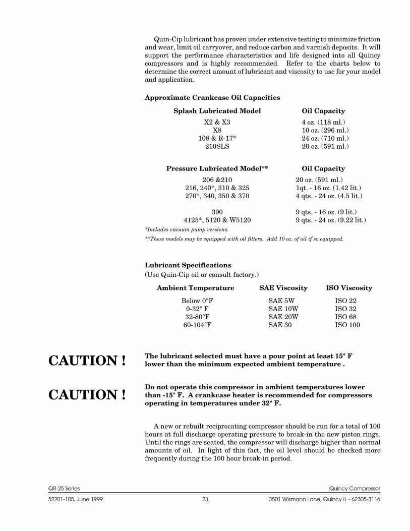
Quin-Cip lubricant has proven under extensive testing to minimize frictionand wear, limit oil carryover, and reduce carbon and varnish deposits. It willsupport the performance characteristics and life designed into all Quincycompressors and is highly recommended. Refer to the charts below todetermine the correct amount of lubricant and viscosity to use for your modeland application.
Approximate Crankcase Oil Capacities
Splash Lubricated Model Oil Capacity
X2 & X3 4 oz. (118 ml.)X8 10 oz. (296 ml.)
108 & R-17* 24 oz. (710 ml.)210SLS 20 oz. (591 ml.)
Pressure Lubricated Model** Oil Capacity
206 &210 20 oz. (591 ml.)216, 240*, 310 & 325 1qt. - 16 oz. (1.42 lit.)270*, 340, 350 & 370 4 qts. - 24 oz. (4.5 lit.)
390 9 qts. - 16 oz. (9 lit.)4125*, 5120 & W5120 9 qts. - 24 oz. (9.22 lit.)
*Includes vacuum pump versions.
**These models may be equipped with oil filters. Add 10 oz. of oil if so equipped.
Lubricant Specifications(Use Quin-Cip oil or consult factory.)
Ambient Temperature SAE Viscosity ISO Viscosity
Below 0°F SAE 5W ISO 220-32° F SAE 10W ISO 3232-80°F SAE 20W ISO 6860-104°F SAE 30 ISO 100
The lubricant selected must have a pour point at least 15° Flower than the minimum expected ambient temperature .
Do not operate this compressor in ambient temperatures lowerthan -15° F. A crankcase heater is recommended for compressorsoperating in temperatures under 32° F.
A new or rebuilt reciprocating compressor should be run for a total of 100hours at full discharge operating pressure to break-in the new piston rings.Until the rings are seated, the compressor will discharge higher than normalamounts of oil. In light of this fact, the oil level should be checked morefrequently during the 100 hour break-in period.
CAUTION !
CAUTION !
QR-25 Series Quincy Compressor
52201-105, June 1999 24 3501 Wismann Lane, Quincy IL - 62305-3116
Pulley / Sheave Alignment & Belt Tension
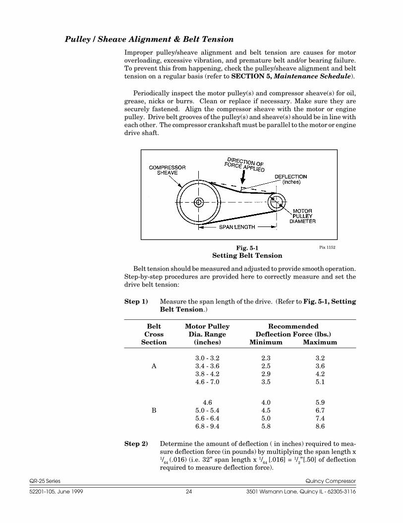
Improper pulley/sheave alignment and belt tension are causes for motoroverloading, excessive vibration, and premature belt and/or bearing failure.To prevent this from happening, check the pulley/sheave alignment and belttension on a regular basis (refer to SECTION 5, Maintenance Schedule).
Periodically inspect the motor pulley(s) and compressor sheave(s) for oil,grease, nicks or burrs. Clean or replace if necessary. Make sure they aresecurely fastened. Align the compressor sheave with the motor or enginepulley. Drive belt grooves of the pulley(s) and sheave(s) should be in line witheach other. The compressor crankshaft must be parallel to the motor or enginedrive shaft.
Belt tension should be measured and adjusted to provide smooth operation.Step-by-step procedures are provided here to correctly measure and set thedrive belt tension:
Step 1) Measure the span length of the drive. (Refer to Fig. 5-1, SettingBelt Tension.)
Belt Motor Pulley RecommendedCross Dia. Range Deflection Force (lbs.)
Section (inches) Minimum Maximum
3.0 - 3.2 2.3 3.2A 3.4 - 3.6 2.5 3.6
3.8 - 4.2 2.9 4.24.6 - 7.0 3.5 5.1
4.6 4.0 5.9B 5.0 - 5.4 4.5 6.7
5.6 - 6.4 5.0 7.46.8 - 9.4 5.8 8.6
Step 2) Determine the amount of deflection ( in inches) required to mea-sure deflection force (in pounds) by multiplying the span length x1/64 (.016) (i.e. 32” span length x 1/64 [.016] = 1/2”[.50] of deflectionrequired to measure deflection force).
Pix 1152Fig. 5-1Setting Belt Tension
QR-25 Series Quincy Compressor
52201-105, June 1999 25 3501 Wismann Lane, Quincy IL - 62305-3116
Pix 1153Fig. 5-2 Belt Tension Gauge
*Full load amps (FLA) & Service Factor can usually be found on the motor nameplate.
Pix 1067Fig. 5-3 Pressure Switch
PRESSUREADJUSTMENT
SCREW
ELECTRICALCONTACTS
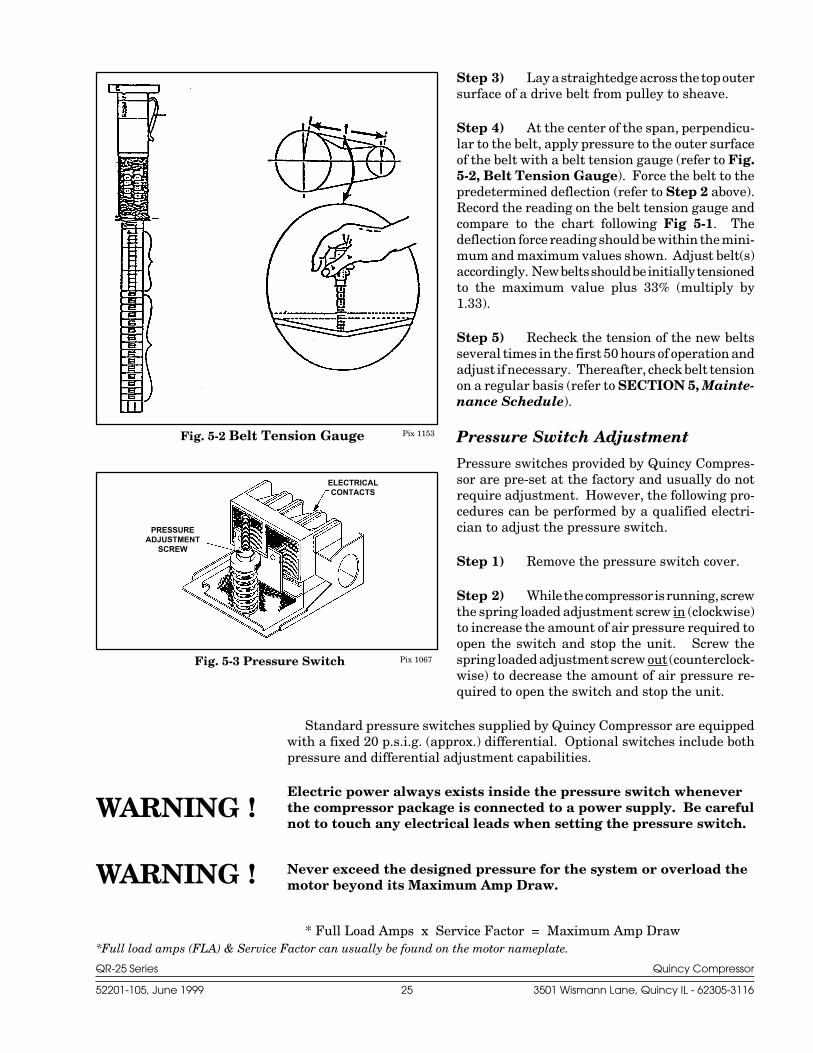
Step 3) Lay a straightedge across the top outersurface of a drive belt from pulley to sheave.
Step 4) At the center of the span, perpendicu-lar to the belt, apply pressure to the outer surfaceof the belt with a belt tension gauge (refer to Fig.5-2, Belt Tension Gauge). Force the belt to thepredetermined deflection (refer to Step 2 above).Record the reading on the belt tension gauge andcompare to the chart following Fig 5-1. Thedeflection force reading should be within the mini-mum and maximum values shown. Adjust belt(s)accordingly. New belts should be initially tensionedto the maximum value plus 33% (multiply by1.33).
Step 5) Recheck the tension of the new beltsseveral times in the first 50 hours of operation andadjust if necessary. Thereafter, check belt tensionon a regular basis (refer to SECTION 5, Mainte-nance Schedule).
Pressure Switch Adjustment
Pressure switches provided by Quincy Compres-sor are pre-set at the factory and usually do notrequire adjustment. However, the following pro-cedures can be performed by a qualified electri-cian to adjust the pressure switch.
Step 1) Remove the pressure switch cover.
Step 2) While the compressor is running, screwthe spring loaded adjustment screw in (clockwise)to increase the amount of air pressure required toopen the switch and stop the unit. Screw thespring loaded adjustment screw out (counterclock-wise) to decrease the amount of air pressure re-quired to open the switch and stop the unit.
Standard pressure switches supplied by Quincy Compressor are equippedwith a fixed 20 p.s.i.g. (approx.) differential. Optional switches include bothpressure and differential adjustment capabilities.
Electric power always exists inside the pressure switch wheneverthe compressor package is connected to a power supply. Be carefulnot to touch any electrical leads when setting the pressure switch.
Never exceed the designed pressure for the system or overload themotor beyond its Maximum Amp Draw.
* Full Load Amps x Service Factor = Maximum Amp Draw
WARNING !
WARNING !
QR-25 Series Quincy Compressor
52201-105, June 1999 26 3501 Wismann Lane, Quincy IL - 62305-3116
Never assume a compressor is safe to work on just because it is notoperating. It may be in the automatic stand-by mode and mayrestart any time. Follow all safety precautions outlined in SEC-TION 5, Stopping For Maintenance.
Reversal of Compressor Rotation
Pressure lubricated QR-25 series compressors can be modified to operate inreverse rotation with exception to the Models 206 & 210. These two modelsoperate in the counterclockwise direction only.
To reverse the operating direction of a pressure lubricated compressor,perform the following steps:
Step 1) Remove:
- the control tubing from the hydraulic unloader and pilot valve (if soequipped).
- the oil pressure gauge and hydraulic unloader.
- the pilot mounting stud set screw and pilot valve assembly.
- the oil filter* (turn counterclockwise).
- six (6) oil pump housing bolts.
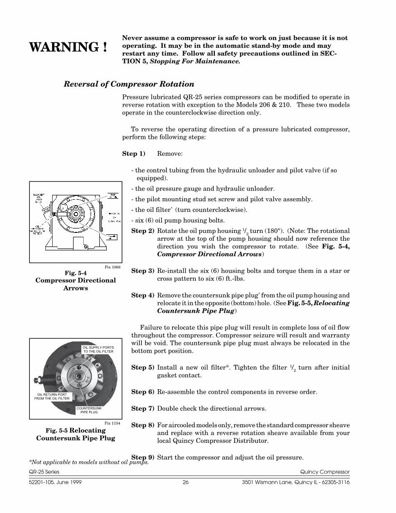
Step 2) Rotate the oil pump housing 1/2 turn (180°). (Note: The rotationalarrow at the top of the pump housing should now reference thedirection you wish the compressor to rotate. (See Fig. 5-4,Compressor Directional Arrows)
Step 3) Re-install the six (6) housing bolts and torque them in a star orcross pattern to six (6) ft.-lbs.
Step 4) Remove the countersunk pipe plug* from the oil pump housing andrelocate it in the opposite (bottom) hole. (See Fig. 5-5, RelocatingCountersunk Pipe Plug)
Failure to relocate this pipe plug will result in complete loss of oil flowthroughout the compressor. Compressor seizure will result and warrantywill be void. The countersunk pipe plug must always be relocated in thebottom port position.
Step 5) Install a new oil filter*. Tighten the filter 1/2 turn after initialgasket contact.
Step 6) Re-assemble the control components in reverse order.
Step 7) Double check the directional arrows.
Step 8) For aircooled models only, remove the standard compressor sheaveand replace with a reverse rotation sheave available from yourlocal Quincy Compressor Distributor.
Step 9) Start the compressor and adjust the oil pressure.
Pix 1068
Fig. 5-4Compressor Directional
Arrows
OIL RETURN PORTFROM THE OIL FILTER
COUNTERSUNKPIPE PLUG
OIL SUPPLY PORTSTO THE OIL FILTER
Pix 1154
Fig. 5-5 RelocatingCountersunk Pipe Plug
*Not applicable to models without oil pumps.
WARNING !
QR-25 Series Quincy Compressor
52201-105, June 1999 27 3501 Wismann Lane, Quincy IL - 62305-3116
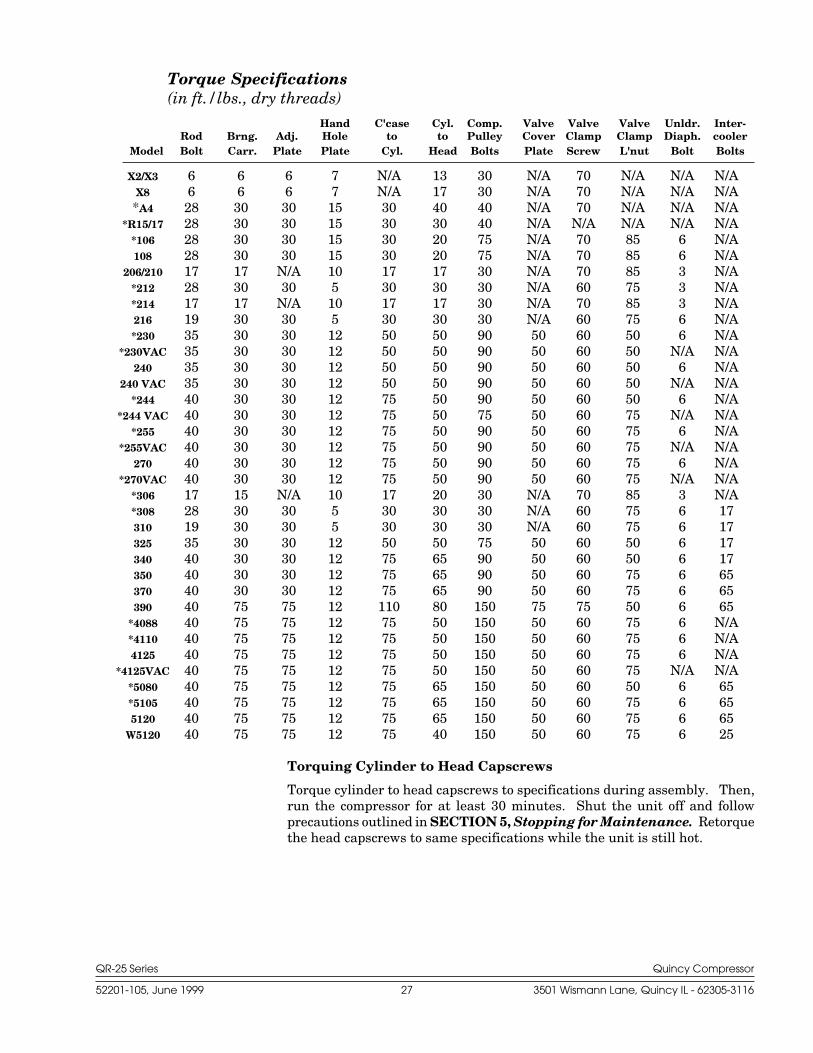
Torque Specifications(in ft./lbs., dry threads)
Hand C'case Cyl. Comp. Valve Valve Valve Unldr. Inter-Rod Brng. Adj. Hole to to Pulley Cover Clamp Clamp Diaph. cooler
Model Bolt Carr. Plate Plate Cyl. Head Bolts Plate Screw L'nut Bolt Bolts
X2/X3 6 6 6 7 N/A 13 30 N/A 70 N/A N/A N/AX8 6 6 6 7 N/A 17 30 N/A 70 N/A N/A N/A*A4 28 30 30 15 30 40 40 N/A 70 N/A N/A N/A
*R15/17 28 30 30 15 30 30 40 N/A N/A N/A N/A N/A*106 28 30 30 15 30 20 75 N/A 70 85 6 N/A108 28 30 30 15 30 20 75 N/A 70 85 6 N/A
206/210 17 17 N/A 10 17 17 30 N/A 70 85 3 N/A*212 28 30 30 5 30 30 30 N/A 60 75 3 N/A*214 17 17 N/A 10 17 17 30 N/A 70 85 3 N/A216 19 30 30 5 30 30 30 N/A 60 75 6 N/A*230 35 30 30 12 50 50 90 50 60 50 6 N/A
*230VAC 35 30 30 12 50 50 90 50 60 50 N/A N/A240 35 30 30 12 50 50 90 50 60 50 6 N/A
240 VAC 35 30 30 12 50 50 90 50 60 50 N/A N/A*244 40 30 30 12 75 50 90 50 60 50 6 N/A
*244 VAC 40 30 30 12 75 50 75 50 60 75 N/A N/A*255 40 30 30 12 75 50 90 50 60 75 6 N/A
*255VAC 40 30 30 12 75 50 90 50 60 75 N/A N/A270 40 30 30 12 75 50 90 50 60 75 6 N/A
*270VAC 40 30 30 12 75 50 90 50 60 75 N/A N/A*306 17 15 N/A 10 17 20 30 N/A 70 85 3 N/A*308 28 30 30 5 30 30 30 N/A 60 75 6 17310 19 30 30 5 30 30 30 N/A 60 75 6 17325 35 30 30 12 50 50 75 50 60 50 6 17340 40 30 30 12 75 65 90 50 60 50 6 17350 40 30 30 12 75 65 90 50 60 75 6 65370 40 30 30 12 75 65 90 50 60 75 6 65390 40 75 75 12 110 80 150 75 75 50 6 65
*4088 40 75 75 12 75 50 150 50 60 75 6 N/A*4110 40 75 75 12 75 50 150 50 60 75 6 N/A4125 40 75 75 12 75 50 150 50 60 75 6 N/A
*4125VAC 40 75 75 12 75 50 150 50 60 75 N/A N/A*5080 40 75 75 12 75 65 150 50 60 50 6 65*5105 40 75 75 12 75 65 150 50 60 75 6 655120 40 75 75 12 75 65 150 50 60 75 6 65
W5120 40 75 75 12 75 40 150 50 60 75 6 25
Torquing Cylinder to Head Capscrews
Torque cylinder to head capscrews to specifications during assembly. Then,run the compressor for at least 30 minutes. Shut the unit off and followprecautions outlined in SECTION 5, Stopping for Maintenance. Retorquethe head capscrews to same specifications while the unit is still hot.
QR-25 Series Quincy Compressor
52201-105, June 1999 28 3501 Wismann Lane, Quincy IL - 62305-3116
SECTION 6SECTION 6SECTION 6SECTION 6SECTION 6 TROUBLESHOOTINGTROUBLESHOOTINGTROUBLESHOOTINGTROUBLESHOOTINGTROUBLESHOOTING
Trouble Probable Cause
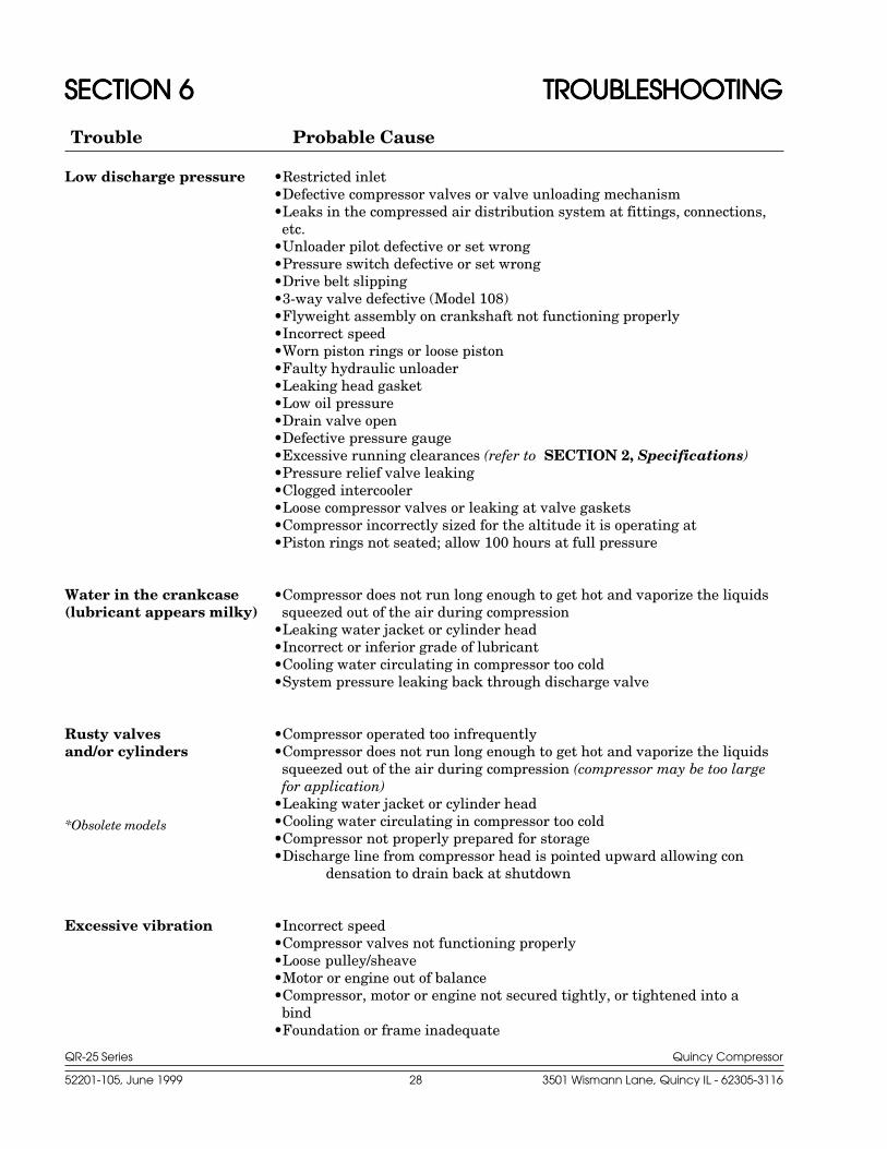
Low discharge pressure •Restricted inlet•Defective compressor valves or valve unloading mechanism•Leaks in the compressed air distribution system at fittings, connections,
etc.•Unloader pilot defective or set wrong•Pressure switch defective or set wrong•Drive belt slipping•3-way valve defective (Model 108)•Flyweight assembly on crankshaft not functioning properly•Incorrect speed•Worn piston rings or loose piston•Faulty hydraulic unloader•Leaking head gasket•Low oil pressure•Drain valve open•Defective pressure gauge•Excessive running clearances (refer to SECTION 2, Specifications)•Pressure relief valve leaking•Clogged intercooler•Loose compressor valves or leaking at valve gaskets•Compressor incorrectly sized for the altitude it is operating at•Piston rings not seated; allow 100 hours at full pressure
Water in the crankcase •Compressor does not run long enough to get hot and vaporize the liquids(lubricant appears milky) squeezed out of the air during compression
•Leaking water jacket or cylinder head•Incorrect or inferior grade of lubricant•Cooling water circulating in compressor too cold•System pressure leaking back through discharge valve
Rusty valves •Compressor operated too infrequentlyand/or cylinders •Compressor does not run long enough to get hot and vaporize the liquids
squeezed out of the air during compression (compressor may be too largefor application)
•Leaking water jacket or cylinder head•Cooling water circulating in compressor too cold•Compressor not properly prepared for storage•Discharge line from compressor head is pointed upward allowing con
densation to drain back at shutdown
Excessive vibration •Incorrect speed•Compressor valves not functioning properly•Loose pulley/sheave•Motor or engine out of balance•Compressor, motor or engine not secured tightly, or tightened into a
bind•Foundation or frame inadequate
*Obsolete models
QR-25 Series Quincy Compressor
52201-105, June 1999 29 3501 Wismann Lane, Quincy IL - 62305-3116
Trouble Probable Cause
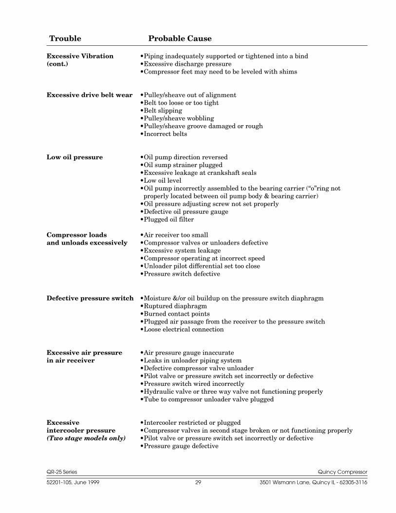
Excessive Vibration •Piping inadequately supported or tightened into a bind(cont.) •Excessive discharge pressure
•Compressor feet may need to be leveled with shims
Excessive drive belt wear •Pulley/sheave out of alignment•Belt too loose or too tight•Belt slipping•Pulley/sheave wobbling•Pulley/sheave groove damaged or rough•Incorrect belts
Low oil pressure •Oil pump direction reversed•Oil sump strainer plugged•Excessive leakage at crankshaft seals•Low oil level•Oil pump incorrectly assembled to the bearing carrier (“o”ring not
properly located between oil pump body & bearing carrier)•Oil pressure adjusting screw not set properly•Defective oil pressure gauge•Plugged oil filter
Compressor loads •Air receiver too smalland unloads excessively •Compressor valves or unloaders defective
•Excessive system leakage•Compressor operating at incorrect speed•Unloader pilot differential set too close•Pressure switch defective
Defective pressure switch •Moisture &/or oil buildup on the pressure switch diaphragm•Ruptured diaphragm•Burned contact points•Plugged air passage from the receiver to the pressure switch•Loose electrical connection
Excessive air pressure •Air pressure gauge inaccuratein air receiver •Leaks in unloader piping system
•Defective compressor valve unloader•Pilot valve or pressure switch set incorrectly or defective•Pressure switch wired incorrectly•Hydraulic valve or three way valve not functioning properly•Tube to compressor unloader valve plugged
Excessive •Intercooler restricted or pluggedintercooler pressure •Compressor valves in second stage broken or not functioning properly(Two stage models only) •Pilot valve or pressure switch set incorrectly or defective
•Pressure gauge defective
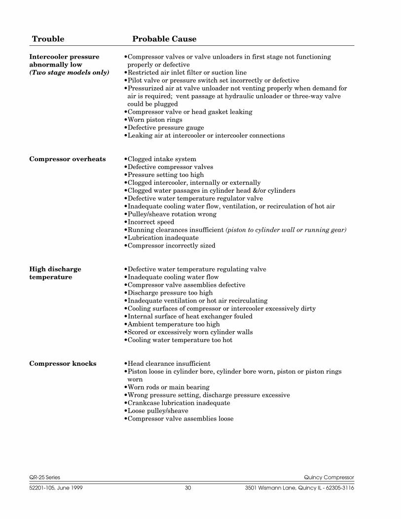
QR-25 Series Quincy Compressor
52201-105, June 1999 30 3501 Wismann Lane, Quincy IL - 62305-3116
Trouble Probable Cause
Intercooler pressure •Compressor valves or valve unloaders in first stage not functioningabnormally low properly or defective(Two stage models only) •Restricted air inlet filter or suction line
•Pilot valve or pressure switch set incorrectly or defective•Pressurized air at valve unloader not venting properly when demand for
air is required; vent passage at hydraulic unloader or three-way valvecould be plugged
•Compressor valve or head gasket leaking•Worn piston rings•Defective pressure gauge•Leaking air at intercooler or intercooler connections
Compressor overheats •Clogged intake system•Defective compressor valves•Pressure setting too high•Clogged intercooler, internally or externally•Clogged water passages in cylinder head &/or cylinders•Defective water temperature regulator valve•Inadequate cooling water flow, ventilation, or recirculation of hot air•Pulley/sheave rotation wrong•Incorrect speed•Running clearances insufficient (piston to cylinder wall or running gear)•Lubrication inadequate•Compressor incorrectly sized
High discharge •Defective water temperature regulating valvetemperature •Inadequate cooling water flow
•Compressor valve assemblies defective•Discharge pressure too high•Inadequate ventilation or hot air recirculating•Cooling surfaces of compressor or intercooler excessively dirty•Internal surface of heat exchanger fouled•Ambient temperature too high•Scored or excessively worn cylinder walls•Cooling water temperature too hot
Compressor knocks •Head clearance insufficient•Piston loose in cylinder bore, cylinder bore worn, piston or piston rings
worn•Worn rods or main bearing•Wrong pressure setting, discharge pressure excessive•Crankcase lubrication inadequate•Loose pulley/sheave•Compressor valve assemblies loose
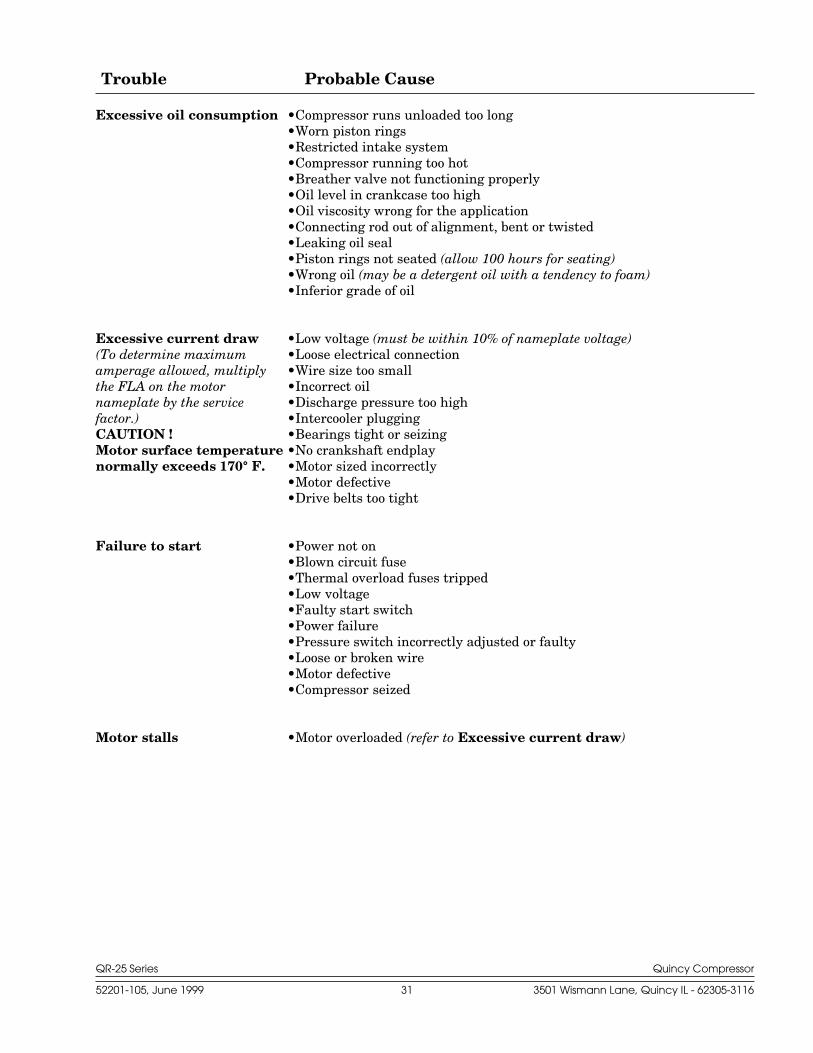
QR-25 Series Quincy Compressor
52201-105, June 1999 31 3501 Wismann Lane, Quincy IL - 62305-3116
Trouble Probable Cause
Excessive oil consumption •Compressor runs unloaded too long•Worn piston rings•Restricted intake system•Compressor running too hot•Breather valve not functioning properly•Oil level in crankcase too high•Oil viscosity wrong for the application•Connecting rod out of alignment, bent or twisted•Leaking oil seal•Piston rings not seated (allow 100 hours for seating)•Wrong oil (may be a detergent oil with a tendency to foam)•Inferior grade of oil
Excessive current draw •Low voltage (must be within 10% of nameplate voltage)(To determine maximum •Loose electrical connectionamperage allowed, multiply •Wire size too smallthe FLA on the motor •Incorrect oilnameplate by the service •Discharge pressure too highfactor.) •Intercooler pluggingCAUTION ! •Bearings tight or seizingMotor surface temperature •No crankshaft endplaynormally exceeds 170° F. •Motor sized incorrectly
•Motor defective•Drive belts too tight
Failure to start •Power not on•Blown circuit fuse•Thermal overload fuses tripped•Low voltage•Faulty start switch•Power failure•Pressure switch incorrectly adjusted or faulty•Loose or broken wire•Motor defective•Compressor seized
Motor stalls •Motor overloaded (refer to Excessive current draw)
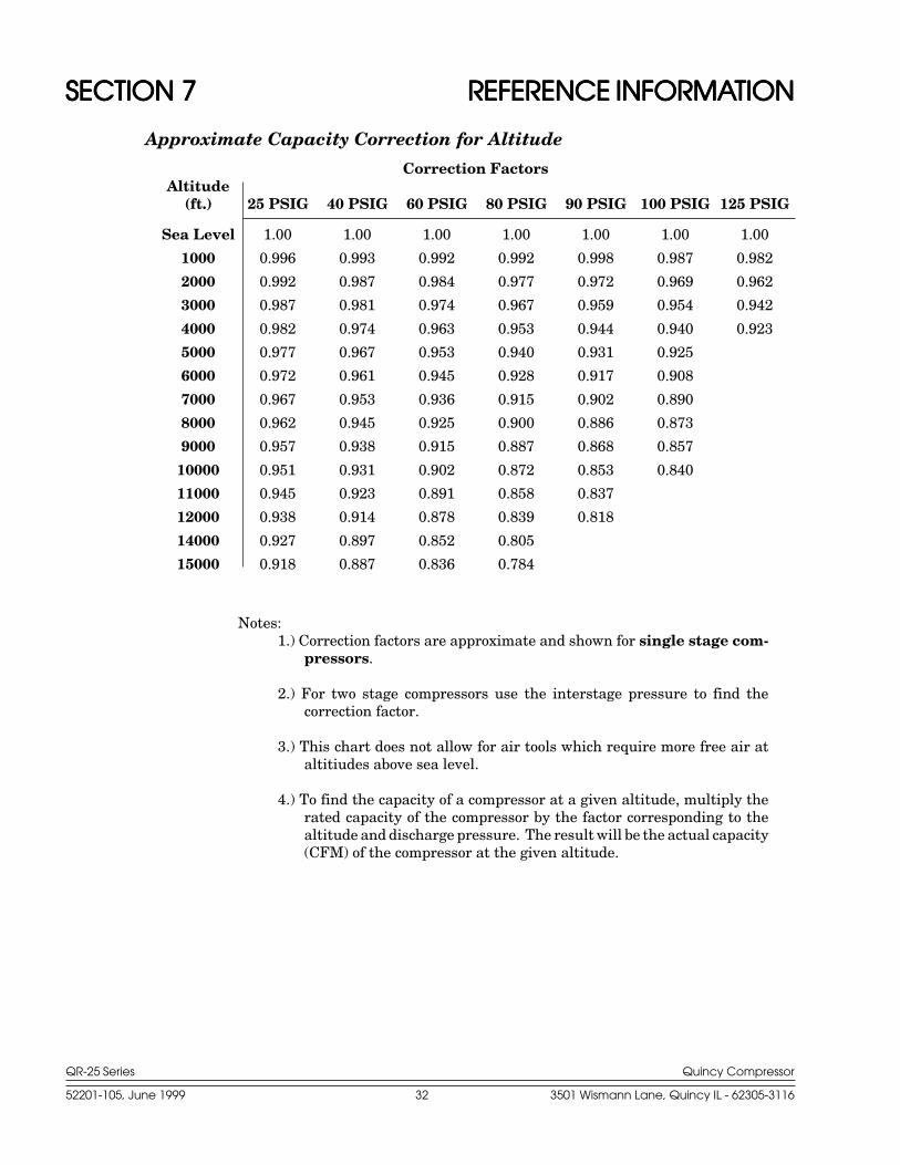
QR-25 Series Quincy Compressor
52201-105, June 1999 32 3501 Wismann Lane, Quincy IL - 62305-3116
SECTION 7SECTION 7SECTION 7SECTION 7SECTION 7 REFERENCE INFORMAREFERENCE INFORMAREFERENCE INFORMAREFERENCE INFORMAREFERENCE INFORMATIONTIONTIONTIONTION
Approximate Capacity Correction for Altitude
Correction FactorsAltitude
(ft.) 25 PSIG 40 PSIG 60 PSIG 80 PSIG 90 PSIG 100 PSIG 125 PSIG
Sea Level 1.00 1.00 1.00 1.00 1.00 1.00 1.00
1000 0.996 0.993 0.992 0.992 0.998 0.987 0.982
2000 0.992 0.987 0.984 0.977 0.972 0.969 0.962
3000 0.987 0.981 0.974 0.967 0.959 0.954 0.942
4000 0.982 0.974 0.963 0.953 0.944 0.940 0.923
5000 0.977 0.967 0.953 0.940 0.931 0.925
6000 0.972 0.961 0.945 0.928 0.917 0.908
7000 0.967 0.953 0.936 0.915 0.902 0.890
8000 0.962 0.945 0.925 0.900 0.886 0.873
9000 0.957 0.938 0.915 0.887 0.868 0.857
10000 0.951 0.931 0.902 0.872 0.853 0.840
11000 0.945 0.923 0.891 0.858 0.837
12000 0.938 0.914 0.878 0.839 0.818
14000 0.927 0.897 0.852 0.805
15000 0.918 0.887 0.836 0.784
Notes:1.) Correction factors are approximate and shown for single stage com-
pressors.
2.) For two stage compressors use the interstage pressure to find thecorrection factor.
3.) This chart does not allow for air tools which require more free air ataltitiudes above sea level.
4.) To find the capacity of a compressor at a given altitude, multiply therated capacity of the compressor by the factor corresponding to thealtitude and discharge pressure. The result will be the actual capacity(CFM) of the compressor at the given altitude.
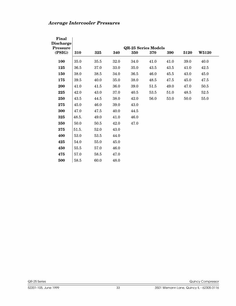
QR-25 Series Quincy Compressor
52201-105, June 1999 33 3501 Wismann Lane, Quincy IL - 62305-3116
Average Intercooler Pressures
FinalDischargePressure QR-25 Series Models
(PSIG) 310 325 340 350 370 390 5120 W5120
100 35.0 35.5 32.0 34.0 41.0 41.0 39.0 40.0
125 36.5 37.0 33.0 35.0 43.5 43.5 41.0 42.5
150 38.0 38.5 34.0 36.5 46.0 45.5 43.0 45.0
175 39.5 40.0 35.0 38.0 48.5 47.5 45.0 47.5
200 41.0 41.5 36.0 39.0 51.5 49.0 47.0 50.5
225 42.0 43.0 37.0 40.5 53.5 51.0 48.5 52.5
250 43.5 44.5 38.0 42.0 56.0 53.0 50.0 55.0
275 45.0 46.0 39.0 43.0
300 47.0 47.5 40.0 44.5
325 48.5. 49.0 41.0 46.0
350 50.0 50.5 42.0 47.0
375 51.5. 52.0 43.0
400 53.0 53.5 44.0
425 54.0 55.0 45.0
450 55.5 57.0 46.0
475 57.0 58.5 47.0
500 58.5 60.0 48.0
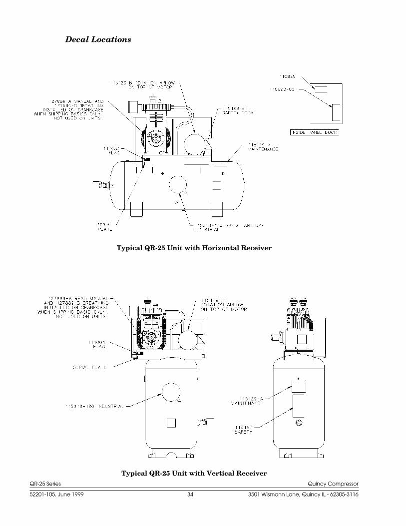
QR-25 Series Quincy Compressor
52201-105, June 1999 34 3501 Wismann Lane, Quincy IL - 62305-3116
Typical QR-25 Unit with Vertical Receiver
Typical QR-25 Unit with Horizontal Receiver
Decal Locations
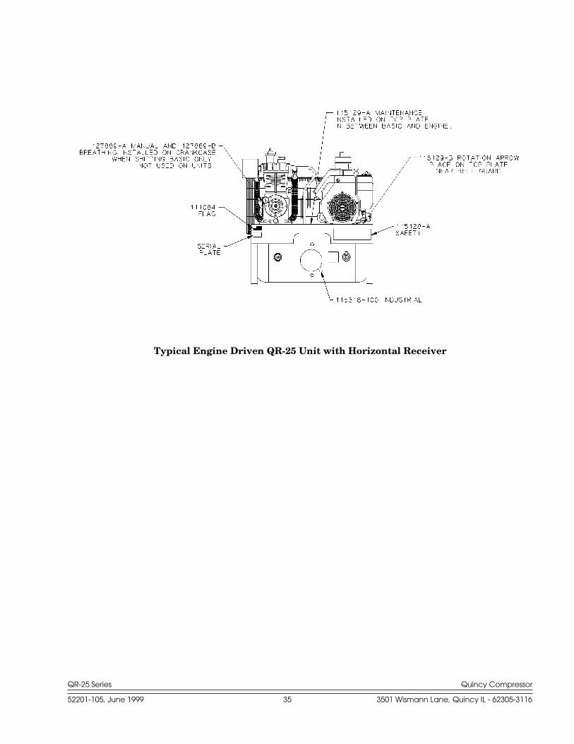
QR-25 Series Quincy Compressor
52201-105, June 1999 35 3501 Wismann Lane, Quincy IL - 62305-3116
Typical Engine Driven QR-25 Unit with Horizontal Receiver

a
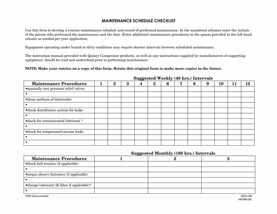
*QRD Series excluded 50253-100mnchklst.doc
MAINTENANCE SCHEDULE CHECKLIST
Use this form to develop a routine maintenance schedule and record of performed maintenance. In the numbered columns enter the initialsof the person who performed the maintenance and the date. Enter additional maintenance procedures in the spaces provided in the left handcolumn as needed per your application.
Equipment operating under humid or dirty conditions may require shorter intervals between scheduled maintenance.
The instruction manual provided with Quincy Compressor products, as well as any instructions supplied by manufacturers of supportingequipment, should be read and understood prior to performing maintenance.
NOTE: Make your entries on a copy of this form. Retain this original form to make more copies in the future.
Suggested Weekly (40 hrs.) IntervalsMaintenance Procedures 1 2 3 4 5 6 7 8 9 10 11 12
•manually test pressure relief valves
•
•clean surfaces of intercooler
•
•check distribution system for leaks
•
•check for contaminated lubricant *
•
•check for compressor/vacuum leaks
•
•
Suggested Monthly (160 hrs.) IntervalsMaintenance Procedures 1 2 3
•check belt tension (if applicable)
•
•torque sheave fasteners (if applicable)
•
•change lubricant (& filter if applicable)*
•

a
See how Quincy Compressors
can work for you. Call 217.222.7700
E-mail: [email protected]© 2002 Quincy CompressorAll Rights Reserved. Litho in U.S.A.
Quincy Service is always near.There are authorized QuincyDistributors located throughoutthe United States & Canada thatstock genuine Quincy parts &accessories for a wide range ofQuincy products.
Quincy Service specialists arefactory trained and will help keepyou in business. Call forAuthorized Quincy Service.