Embed Size (px)
Citation preview

Industrial L2+ Multi-Port Full Gigabit
Managed Ethernet Switch
IGS-5225-4T2S/IGS-5225-4UP1T2S/IGS-5225-8P2S/
IGS-5225-8P4S/IGS-5225-8T2S2X/IGS-5225-8P2S2X
Quick Installation Guide
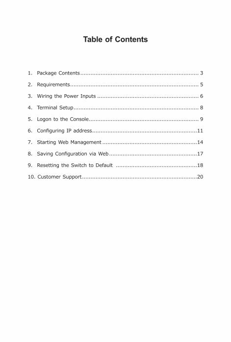
Table of Contents
1. Package Contents ...................................................................... 3
2. Requirements ............................................................................ 5
3. Wiring the Power Inputs ............................................................ 6
4. Terminal Setup .......................................................................... 8
5. Logon to the Console ................................................................. 9
6. ConfiguringIPaddress ..............................................................11
7. Starting Web Management ........................................................14
8. SavingConfigurationviaWeb ....................................................17
9. Resetting the Switch to Default ................................................18
10. Customer Support ....................................................................20

3
1. Package ContentsThank you for purchasing PLANET L2+ Industrial Managed Switch,IGS-5225Series.Thedescriptionsofthesemodelsareasfollows:
IGS-5225-4T2S:IndustrialL2+4-Port10/100/1000T+2-Port100/1000XSFPManagedSwitch
IGS-5225-4UP1T2S:IndustrialL2+4-Port10/100/1000TUltraPoE+1-Port10/100/1000T+2-Port100/1000XSFPManagedSwitch
IGS-5225-8P2S:IndustrialL2+8-Port10/100/1000T802.3atPoE+2-Port100/1000XSFPManagedEthernetSwitch
IGS-5225-8P4S:IndustrialL2+8-Port10/100/1000T802.3atPoE+4-Port100/1000XSFPManagedEthernetSwitch
IGS-5225-8T2S2X:IndustrialL2+8-Port10/100/1000T+2-Port100/1000XSFP+2-Port10GSFP+ManagedEthernet Switch
IGS-5225-8P2S2X:IndustrialL2+8-Port10/100/1000T802.3atPoE+2-Port100/1000XSFP+2-Port10GSFP+ManagedEthernetSwitch
“Industrial Managed Switch” mentioned in this Quick InstallationGuidereferstotheabovesixmodels.

4
Open the box of the Industrial Managed Switch and carefullyunpackit.Theboxshouldcontainthefollowingitems:
z TheIndustrialManagedSwitchx1
z QuickInstallationGuidex1
z DINRailKitx1
z WallMountingKitx1
z DB9toRJ45InterfaceRS232ConsoleCablex1
z Dust Cap (Please refer to the table below.)
RJ45 Dust Cap SFPDustCap
IGS-5225-4T2S 5 2
IGS-5225-8P2S 9 2
IGS-5225-8P4S 9 4
IGS-5225-8T2S2X 9 4
IGS-5225-8P2S2X 9 4
IGS-5225-4UP1T2S 6 2
If any of these are missing or damaged, please contact your dealerimmediately.Ifpossible,retainthecartonincludingtheoriginalpackingmaterials to enable you to repack theproduct in case there is aneedto return it to us for repair.

5
2. RequirementsThe Industrial Managed Switch provides remote login interface for management purposes. The following equipment is necessary for furthermanagement:
z Workstations running Windows XP/2003/Vista/7/8/2008/10, MACOS X or later, Linux, UNIX, or other platforms are compatible withTCP/IPProtocols.
z Workstations are installed with Ethernet NIC (Network InterfaceCard)
z Serial Port Connection (Terminal)
The above Workstations come with COM Port (DB9) or USB-to-RS232 converter.
The above Workstations have been installed with terminalemulator, such as Hyper Terminal included in Windows XP/2003,putty or tera term.
Serial cable -- one end is attached to the RS232 serial port,while theotherend to the consoleportof the IndustrialManagedSwitch.
z Ethernet Port Connection
Network cables -- Use standard network (UTP) cables with RJ45connectors.
The above PC is installed with Web browser and JAVA runtimeenvironment plug-in.
Note
It is recommended touse InternetExplore8.0orabovetoaccesstheIndustrialManagedSwitch.

6
3. Wiring the Power InputsThe Upper Panel of the Industrial Managed Switch indicates a DCinlet power socket and consists of one terminal block connectorwithin6 contacts. Please follow the steps below to insert the power wire.
1.Insert positive/negative DC power wires into Contacts 1 and 2 forPower1,orContacts5and6forPower2.
IGS-5225-8P2S/IGS-5225-8P4S/IGS-5225-8P2S2X/IGS-5225-4UP1T2S:48~56VDC
Input DC 48-56V
DI0 DI1 DO0 DO1 GND GND
DC1+
DC2Fault+
1A@24V
1 2 3 4 5 6
1 2 3 4 5 6
Figure 3-1: IGS-5225-8P2S/IGS-5225-8P4S/IGS-5225-8P2S2X/ IGS-5225-4UP1T2S Upper Panel
IGS-5225-8T2S2X:12~48VDC,24VAC
Input DC 12V~48V AC 24VDC1 DC2Fault
1A@24V
DI1 DO0 DO1DI0 GNDGND
1 2 3 4 5 6
1 2 3 4 5 6
Figure 3-2: IGS-5225-8T2S2X Upper Panel

7
IGS-5225-4T2S:12~48VDC,24VAC
InputDC12~48VAC 24VDC1 DC2Fault
V1-V1+ V2+ V2-1A@24V
1 2 3 4 5 6
Figure 3-3: IGS-5225-4T2S Upper Panel
2. Tighten the wire-clamp screws for preventing the wires from loos-ening.
1 2 3 4 5 6V+ V- V+ V-Power 1 Power 2
Positive (+) Pin Negative (-) Pin
IGS-5225 Series Pin1/5 Pin2/6
Note
The wire gauge for the terminal block should be in therange from 12 to 24 AWG.

8
4. Terminal SetupTo configure the system, connect a serial cable to a COM port on aPCornotebookcomputerandtoRJ45typeserial(console)portof theIndustrialManagedSwitch.Theconsoleportof the IndustrialManagedSwitch is DCE already, so that you can connect the console portdirectlythroughPCwithouttheneedofnullmodem.
PC/Workstationwith
Terminal emulation software
RJ45 to DB9 RS232 CableSerial Port
IP Address:192.168.0.100
IGS Industrial Managed Switch
Aterminalprogram is required tomake thesoftwareconnected to theIGS-5225seriesIndustrialManagedSwitch.
1. Run terminal program on the OS.
2.When the following screen appears, make sure that the COM portshouldbeconfiguredas:
z Baud:115200
z Parity:None
z Databits:8
z Stopbits:1
z Flowcontrol:None
9
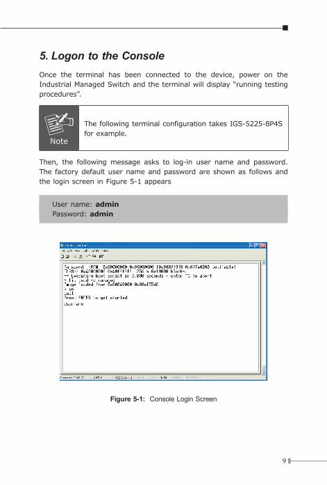
5. Logon to the ConsoleOnce the terminal has been connected to the device, power on theIndustrialManagedSwitchandtheterminalwilldisplay“runningtestingprocedures”.
Note
The following terminal configuration takes IGS-5225-8P4S forexample.
Then, the followingmessage asks to log-in user name and password.The factorydefaultusernameandpasswordareshownas followsandtheloginscreeninFigure5-1appears
Username:adminPassword: admin
Figure 5-1: Console Login Screen

10
Theuser cannowenter commands tomanage the IndustrialManagedSwitch.Foradetaileddescriptionofthecommands,pleaserefertothefollowing chapters.
Note
1. For security reason,please change and memorize the new password after this first setup.
2. Only accept command in lowercase letter underconsole interface.

11
6.ConfiguringIPaddressThe Industrial Managed Switch is shipped with default IP addressshownbelow:
IPAddress:192.168.0.100SubnetMask:255.255.255.0
To check the current IP address or modify a new IP address for theSwitch,pleaseusetheprocedureasfollows:
Display of the current IP Address
1. At the “#”prompt,enter“show ip interface brief”.
2.ThescreendisplaysthecurrentIPaddressshowninFigure6-1.
Figure 6-1: IP Information Screen

12
ConfigurationoftheIPAddress
3. At the “#”prompt,enterthefollowingcommandandpress<Enter> asshowninFigure6-2.
IGS-5225-8P4S# configureterminalIGS-5225-8P4S(config)#interface vlan 1IGS5225-8P4S(config-if-vlan)#ip address 192.168.1.100 255.255.255.0
The previous command would apply the following settings for theIndustrialManagedSwitch.
IPAddress:192.168.1.100SubnetMask:255.255.255.0
Figure 6-2: Configuring IP Address Screen
4.Repeatstep1tocheckiftheIPaddresshaschanged.

13
Storethecurrentswitchconfiguration
5. At the “#”prompt,enterthefollowingcommandandpress<Enter>.
#copyrunning-configstartup-config
Figure 6-3: Saving Current Configuration Command Screen
If the IP is successfully configured, the IndustrialManagedSwitchwillapplythenewIPaddresssetting immediately.YoucanaccesstheWebinterfaceoftheIndustrialManagedSwitchthroughthenewIPaddress.
Note
Ifyouarenot familiarwiththeconsolecommandortherelated parameter, enter “help” anytime in console to getthehelpdescription.

14
7. Starting Web ManagementThe following shows how to start up the Web Management of the Industrial Managed Switch. Note the Industrial Managed Switch isconfigured through an Ethernet connection. Please make sure themanager PC must be set to the same IP subnet address.
Forexample,thedefaultIPaddressoftheIndustrialManagedSwitchis192.168.0.100, then themanager PC should be set to192.168.0.x (where x is a number between 1 and 254, except 100), and thedefaultsubnetmaskis255.255.255.0.
IP Address:192.168.0.x IP Address:
192.168.0.100
IGS Industrial Switch
RJ45/UTP-Cable
Figure 7-1: IP Management Diagram
Logging in to the Industrial Managed Switch
1.Use Internet Explorer 8.0 or above for Web browser and enter IPaddress http://192.168.0.100 (the factory-default IP address) toaccess the Web interface.
2.Whenthefollowingdialogboxappears,pleaseenterthedefaultusername “admin” and password “admin” (or the password you havechangedbefore)asshowninFigure7-2.

15
DefaultIPAddress:192.168.0.100DefaultUserName:adminDefaultPassword:admin
Figure 7-2: Login Screen
3.After entering the password, the main screen appears as shown inFigure7-3.
Figure 7-3: Web Main Screen of Industrial Managed Switch

16
The Switch Menu on the left of the Web page lets you access all the functionsandstatustheIndustrialManagedSwitchprovides.
Now, you can use the Web management interface to continue theSwitch management. Please refer to the user manual for more.
Note
If you are not familiar with Switch functions or the related parameter, press “Help icon” anytime on the Webpagetogetthehelpdescription.

17
8.SavingConfigurationviaWebIn the IndustrialManagedSwitch, the running configuration file storesintheRAM.Inthecurrentversion, therunningconfigurationsequenceof running-config can be saved from the RAM to FLASH by executingsave startup config command, so that the running configurationsequence becomes the startup configuration file, which is calledconfigurationsave.
To save all applied changes and set the current configuration as astartup configuration, the startup-configuration file will be loadedautomatically across a system reboot.
1. Click System,SaveStartupConfig.
2. Press the “SaveConfiguration” button.

18
9. Resetting the Switch to Default To reset the IP address to the default IP address “192.168.0.100” and the user password to factory default mode (default passwordis admin), press the hardware reset button on the front panel forabout 10 seconds. After the device is rebooted, you can login themanagement Web interface within the same subnet of 192.168.0.xxand default password. Be noted that all the previous setups will bedisappearedafterthefactorydefaultresetismade.
P1 P2 FAULT
Ring
RESET
115200,N,8,1
1000LNK/ACT
R.O.
6
Reset
Figure 8-1: IGS-5225-4T2S Reset Button

19
Reset
ACTLNK9
LNK/ACT1000LNK/ACT1000
10
RESET
9
Console
115200,N,8,1
10
100/1000X SFP
ACTLNK
PoE In-Use
P1
Ring
P2 FAULT
R.O. I/O
240W
PoE Power Usage
180W
120W
60W
Figure 8-2: IGS-5225-8P2S/IGS-5225-4UP1T2S Reset Button
IGS-5225-8P2S2X
5
3
1
RESET
6
4
2
LNK
PoE In-Use
ACT
802.3at PoE
Reset
Figure 8-3: IGS-5225-8P4S/IGS-5225-8T2S2X/IGS-5225-8P2S2X Reset Button

20
10. Customer SupportThankyouforpurchasingPLANETproducts.YoucanbrowseouronlineFAQ resource on PLANETweb site first to check if it could solve yourissue. If you need more support information, please contact PLANETswitch support team.
PLANETonlineFAQ:http://www.planet.com.tw/en/support/faq.php
Switchsupportteammailaddress:[email protected]
IGS-5225-4T2S/IGS-5225-8P2S/IGS-5225-8P4S/IGS-5225-8T2S2X/IGS-5225-8P2S2X/IGS-5225-4UP1T2SUser’sManual:http://www.planet.com.tw/en/support/download.php?type1=22153&model=&type=3
(Please select your switchmodel name from the Product Model drop-downmenu)
Copyright © PLANET Technology Corp. 2017.Contents are subject to revision without prior notice.PLANET is a registered trademark of PLANET Technology Corp.All other trademarks belong to their respective owners.


![courtnaye kit · {v Z} }(Z o}P } Z }vÁ ] µ Z ÁÁÁ X } Á olX }uUÁÁÁ X] o] À X }uU ÁÁÁ XZ Ç À v X }uUíììXó&D](https://img.pdfslide.us/doc/110x75/6065aa934bb79c17bf168675/courtnaye-v-z-z-op-z-v-z-x-olx-uu-x-o-x-uu.jpg)


![v À ] ] sK...v v d Z ] u v µ oDh^d P ] À v } Z µ } ( Z } µ X &KZ µ ] v P Z ] } µ U Z ] u v µ o v À ( } ( µ µ ( v X í' v o X X X X X X X X X X X X X X X X X X X X X X](https://img.pdfslide.us/doc/110x75/60d890cdc032525f853d6a38/-v-sk-v-v-d-z-u-v-odhd-p-v-z-z-x-kz-.jpg)
![æ á z x x z x x z - Eiger Design...À ] } v ] hhd Á Z ] Z Z À µ o U µ v v U } u u µ v ] ] } v µ X Z Z/E ð î õ v ] À Z ï î v u ]](https://img.pdfslide.us/doc/110x75/5f76324c5f12f159f479efd2/-z-x-x-z-x-x-z-eiger-v-hhd-z-z-z-o-u-v-v-u-u.jpg)
![^ u Z } v W Z } } P Z Ç 2018 Smartphone... · ^ u Z } v W Z } } P Z Ç W v Ç E ] o ^ Z u ] ^ u Z } v W Z } } P Z Ç X X X o ] o l P } µ v X X X](https://img.pdfslide.us/doc/110x75/5f91848f2c6be7522a3ab49b/-u-z-v-w-z-p-z-2018-smartphone-u-z-v-w-z-p-z-w-v-e.jpg)
![} µ µ ^ d } o W ] } } µ µ E u DZW ~Z X ZW ~Z X '^d ~Z X...E u } µ µ ^ E } X } } µ µ E u DZW ~Z X ZW ~Z X '^d ~Z X d } o W ] ~Z X ] v o d Æ Z v v o > ] ^ t } o W u ] , hds](https://img.pdfslide.us/doc/110x75/5e578cca47ad0d78834c2053/-d-o-w-e-u-dzw-z-x-zw-z-x-d-z-x-e-u-e.jpg)


![Imam Hussain Dilruba e Qolob Hussain Dilruba...* n† x z−zg−gzZc 2 ‡ y¤ Z ]ZfkZ gzx gzZc † _ Žfl g0 Z ‹ kZ&6 ~ kZ ... Z‘ z− x Z " ¾ z− x Z xZ Z. ⁄ x Z ‹w g](https://img.pdfslide.us/doc/110x75/5abc873b7f8b9a24028ded97/imam-hussain-dilruba-e-hussain-dilruba-n-x-zzggzzc-2-y-z-zfkz.jpg)


![, Zs z z /E X · , Zs z z /E X u ] v µ Z À Ç Ç X } P X µ W í µ v ] À U h v P v X](https://img.pdfslide.us/doc/110x75/5ecbcfd3f212d6189e267bb5/-zs-z-z-e-x-zs-z-z-e-x-u-v-z-x-p-x-w-v-u-h-v.jpg)