Embed Size (px)
Citation preview

LIFTEKNIC
Qube Lift Control System
Operating Instructions Issue 2.0
Lifteknic Limited 11 Victoria Road • Chester • Cheshire CH2 2AX
Tel. +44(0)1244 389690 • Fax. +44(0)1244 389691 e-mail:[email protected]
subject to change without notice!

LIFTEKNIC
Qube Lift Control System Page 2 / 92 Date 12-Apr-11
Operating Instructions Issue 2.0
subject to change without notice!
General Information
The manufacturer accepts no liability for any consequences resulting from inappropriate, negligent, incorrect installation or adjustment of the optional operating parameters of the equipment. The contents of this Operating Manual are believed to be correct at the time of printing. In the interests of commitment to a policy of continuous development and improvement, the manufacturer reserves the right to change the specification of the product, its performance or the contents of the Operating Manual without notice. All rights reserved. No part of this Operating Manual may be reproduced or transmitted in any form or by any means, electrical or mechanical including photocopying, recording or by any information storage or retrieval system, without permission in writing from the publisher.
Controller Software (Qube 75 onwards)
This product is supplied with the latest version of Qube lift control software. If this product is to be used in a new or existing lift system with other controllers, there may be some differences between their software and the software in this product which may cause the product to function differently. If there is any doubt, please contact Lifteknic Limited.
Copyright © June 2008 Lifteknic Limited Qube® is a registered trademark
LIFTEKNIC
Qube Lift Control System Page 3 / 92 Date 12-Apr-11
Operating Instructions Issue 2.0
subject to change without notice!
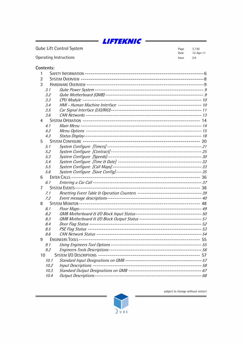
Contents: 1 SAFETY INFORMATION --------------------------------------------------------------6 2 SYSTEM OVERVIEW ----------------------------------------------------------------8 3 HARDWARE OVERVIEW -------------------------------------------------------------9
3.1 Qube Power System ------------------------------------------------------------- 9 3.2 Qube Motherboard (QMB) ------------------------------------------------------- 9 3.3 CPU Module ------------------------------------------------------------------- 10 3.4 HMI - Human Machine Interface ----------------------------------------------- 10 3.5 Car Signal Interface (LIO/RIO)--------------------------------------------------- 11 3.6 CAN Networks ----------------------------------------------------------------- 13
4 SYSTEM OPERATION ------------------------------------------------------------- 14 4.1 Main Menu -------------------------------------------------------------------- 14 4.2 Menu Options ----------------------------------------------------------------- 15 4.3 Status Display------------------------------------------------------------------ 18
5 SYSTEM CONFIGURE ------------------------------------------------------------- 20 5.1 System Configure [Timers] ----------------------------------------------------- 21 5.2 System Configure [Contract] --------------------------------------------------- 25 5.3 System Configure [Speeds]----------------------------------------------------- 30 5.4 System Configure [Time & Date] ----------------------------------------------- 32 5.5 System Configure [Call Maps] -------------------------------------------------- 33 5.6 System Configure [Save Config]------------------------------------------------ 35
6 ENTER CALLS ------------------------------------------------------------------- 36 6.1 Entering a Car Call ------------------------------------------------------------- 37
7 SYSTEM EVENTS----------------------------------------------------------------- 38 7.1 Resetting Event Table & Operation Counters ------------------------------------ 39 7.2 Event message descriptions----------------------------------------------------- 40
8 SYSTEM MONITOR--------------------------------------------------------------- 48 8.1 Floor Maps--------------------------------------------------------------------- 49 8.2 QMB Motherboard & I/O Block Input Status------------------------------------- 50 8.3 QMB Motherboard & I/O Block Output Status ----------------------------------- 51 8.4 Door Flag Status --------------------------------------------------------------- 52 8.5 PSE Flag Status ---------------------------------------------------------------- 53 8.6 CAN Network Status ----------------------------------------------------------- 54
9 ENGINEERS TOOLS --------------------------------------------------------------- 55 9.1 Using Engineers Tool Options --------------------------------------------------- 55 9.2 Engineers Tools Descriptions ---------------------------------------------------- 56
10 SYSTEM I/O DESCRIPTIONS ----------------------------------------------------- 57 10.1 Standard Input Designations on QMB ------------------------------------------- 57 10.2 Input Descriptions ------------------------------------------------------------- 58 10.3 Standard Output Designations on QMB ----------------------------------------- 67 10.4 Output Descriptions------------------------------------------------------------ 68

LIFTEKNIC
Qube Lift Control System Page 4 / 92 Date 12-Apr-11
Operating Instructions Issue 2.0
subject to change without notice!
11 UNIVERSAL INTERFACE BOARD--------------------------------------------------- 71 11.1 Switch settings for landing node ----------------------------------------------- 71 11.2 Switch settings for expansion I/O node------------------------------------------ 73 11.3 Binary Reference Table --------------------------------------------------------- 74
12 MOUNTING THE PANELS-------------------------------------------------------- 76 12.1 Floor Standing ----------------------------------------------------------------- 76 12.2 Wall mounted ----------------------------------------------------------------- 76
13 QUICK START ROUTINE FOR QUBE MICRO WITH UNIDRIVESP DRIVE---------------------- 77 14 UNIDRIVE SP – STANDARD LIFT DRIVE -------------------------------------------- 80
14.1 Introduction ------------------------------------------------------------------- 80 14.2 Assigning parameters ---------------------------------------------------------- 80 14.3 Basic settings for Open Loop(O.Lp) & Closed Loop(C.Lp) Operation---------------- 81 14.4 Smart card programming------------------------------------------------------- 83 14.5 Saving and restoring complete parameter sets to and from the Smartcard-------- 83 14.6 System start-up on site--------------------------------------------------------- 84 14.7 Optimising the brake controller------------------------------------------------- 88

LIFTEKNIC
Qube Lift Control System Page 5 / 92 Date 12-Apr-11
Operating Instructions Issue 2.0
subject to change without notice!
LIFTEKNIC
Declaration Of Conformity
The Qube control system has been designed and manufactured in accordance with the following European, national and international standards: EN12015 : 2004 EMC Emissions EN12016 : 2004 EMC Immunity NEN-EN81-1 / NEN-EN81-2 * Type Examination *(article 14.1.1, 14.1.2.3, annex H)
Paul Catherall General Manager
This controller is intended to be used with an appropriate motor, drive, electrical components and other equipment to form a complete system. It must only be installed by a professional who is familiar with the requirements for safety and electromagnetic compatibility (EMC). The installer is responsible for ensuring that the end product complies with all the relevant laws of the country of installation.
Lifteknic Limited 11 Victoria Road Chester Cheshire CH2 2AX Phone +44(0) 1244 389690 Fax +44(0) 1244 389691 http://www.lifteknic.co.uk

LIFTEKNIC
Qube Lift Control System Page 6 / 92 Date 12-Apr-11
Operating Instructions Issue 2.0
subject to change without notice!
1 Safety Information Assessment of risks during installation of lift control equipment Personnel
All installation, commissioning and servicing of electrical and electronic components within the lift control system must be performed by, or supervised by, suitably qualified personnel (i.e. personnel that have appropriate training and knowledge of regulations that allow them to judge the quality of the work performed and identify the possible dangers). Any personnel working on Lifteknic products are responsible for their own safety.
Documentation All documentation supplied with the lift control system must be made available to personnel working on the lift control equipment, with particular attention being paid to the safety notices and the recommendations contained therein. This manual is not contract specific and must be read in conjunction with the contract electrical diagrams related to the specific lift installation(s).
Residual dangers Residual dangers that exist when installing or working on lift control equipment are listed below. Danger to personnel
Danger to life • Risk of electric shock from live parts when working on electrical equipment. • Risk of falling down the lift shaft when working on the car top or in the lift shaft Risk of injury • When moving or lifting control cubicle if equipment falls or tips over • When working in lift shaft while lift is moving • When working on control equipment that may be very hot due to recent use
Damage to equipment • Risk of damage to control componentry due to excess voltages or short circuits
This list is not considered exhaustive and due consideration for the safety of personnel and equipment must be exercised at all times.
LIFTEKNIC
Qube Lift Control System Page 7 / 92 Date 12-Apr-11
Operating Instructions Issue 2.0
subject to change without notice!
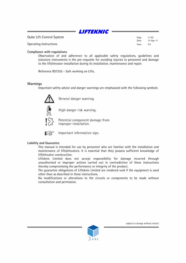
Compliance with regulations Observation of and adherence to all applicable safety regulations, guidelines and statutory instruments is the pre-requisite for avoiding injuries to personnel and damage to the lift/elevator installation during its installation, maintenance and repair.
Reference BS7255 - Safe working on Lifts.
Warnings Important safety advice and danger warnings are emphasized with the following symbols:
Liability and Guarantee
This manual is intended for use by personnel who are familiar with the installation and maintenance of lifts/elevators. It is essential that they possess sufficient knowledge of lift/elevator construction. Lifteknic Limited does not accept responsibility for damage incurred through unauthorised or improper actions carried out in contradiction of these instructions thereby compromising the performance or integrity of the product. The guarantee obligations of Lifteknic Limited are rendered void if the equipment is used other than as described in these instructions. No modifications or alterations to the circuits or components to be made without consultation and permission.

LIFTEKNIC
Qube Lift Control System Page 8 / 92 Date 12-Apr-11
Operating Instructions Issue 2.0
subject to change without notice!
2 System Overview Introduction
The Qube range of control systems are the product of many years experience and investment in lift control technology. It is commitment to innovation that has seen Lifteknic become one of the global market leaders for lift control systems. The Qube is the basis for a range of control systems offering outstanding performance and functionality at affordable prices. Together with a wide range of drive options, this ensures the flexibility to cope with any project demand.
Design & Build Quality Only the highest quality components and manufacturing techniques are used throughout production, resulting in a highly reliable product that can be considered without question as a sound investment in the future of a lift installation.
Floor Capability
The Qube can serve up to 64 floors in any call mode (i.e. APB, non-selective collective, down collective or full collective). The car signal interface can be mounted on the controller (LIO) or on the top of the lift car (RIO). Using the RIO on the car-top drastically reduces the number of trailing cables required for a given installation. The landing calls and associated call registration buzzer are interfaced to the main controller via a universal interface, connected to the landing CAN network at each floor.
Door Capability
The Qube provides a full set of controls for two independently operated car doors. These may be configured to operate in selective or non-selective mode to suit the specific application.
Drives
The Qube system can be adapted to suit any site condition and is available to suit any drive format which includes the following: Geared AC induction motor - VVVF control Geared/Gearless AC induction motor - flux vector control (sinusoidal mains regeneration option) Gearless AC synchronous motor - servo control (sinusoidal mains regeneration option) Geared/Gearless DC motor – 6-pulse SCR 12-pulse SCR or Ward-Leonard control Hydraulic with VVVF control for pump
The drive products currently used in conjunction with the Qube lift control system are provided by Control Techniques.
LIFTEKNIC
Qube Lift Control System Page 9 / 92 Date 12-Apr-11
Operating Instructions Issue 2.0
subject to change without notice!
3 Hardware Overview 3.1 Qube Power System Safety circuit voltage - 110Vac Signal voltage - 24Vdc Power Supply Unit An DC UPS is utilised for the QMB motherboard and signal supply ensuring that power is maintained to the main motherboard and the positioning system in the event of a power failure. Input voltage 85Vac - 250Vac Output voltage 24Vdc @ 5A 3.2 Qube Motherboard (QMB) Power supply connector (JP25) 24Vdc supply from PSU CAN port 1 (JP23) CAN communication port for expansion nodes, position system encoder and Qube position indicator in lift car. CAN port 2 (JP30 & JP18) CAN communication port for duplexing data CAN port 3 (JP13) CAN communication port for Qube position indicators on landings Serial port (P1) Serial port for downloading new software. Inputs (JP6, JP8 & JP4) The inputs to the Qube control system are connected to the left-hand side of the motherboard. Each of the three connectors has an earth pin and a common pin. In the case of the 110Vac inputs (1-16), the common track must be connected into the control circuit return, between the supply and the return feed of the main contactors. This is to ensure that if a problem arises with the safety circuit monitoring inputs that the main contactor return path is disabled (i.e. preventing further movement of the lift). Input Connector 1 (JP6) Inputs 1-8 110Vac - safety circuit Input Connector 2 (JP8) Inputs 9-16 110Vac - safety circuit Input Connector 3 (JP4) Inputs 17-24 24Vdc - positioning signals

LIFTEKNIC
Qube Lift Control System Page 10 / 92 Date 12-Apr-11
Operating Instructions Issue 2.0
subject to change without notice!
Outputs (JP2, JP3, JP5 & JP7) All the outputs on the Qube motherboad (QMB) are fed via an Output Enable relay (OEN). This relay, mounted on the top left-hand side of the QMB, ensures that the supply for the output relays is only switched on if the main program is functioning correctly. If the main program does not execute in the correct way, the output enable relay will be released causing all output relays to be released. The output connections are arranged in the following way; Output Connector 1 (JP2) Outputs 1-4 Output Connector 2 (JP3) Outputs 5-8 Output Connector 3 (JP5) Outputs 9-16 Output Connector 4 (JP7) Outputs 17-24 3.3 CPU Module The central processor unit contains and executes the Qube lift software. It employs a software and hardware watchdog, that monitors code execution and resets the device if a problem is detected. 3.4 HMI - Human Machine Interface The on-board HMI (Human Machine Interface) comprises a 4 line x20 character LCD module with 4-buttons and is a simple to use, fully featured user interface that allows easy access to the Qube system information. Functions accessible through the HMI are listed below; Setting up contract specific parameters Setting time and date, etc. Securing floors Entering calls Viewing system events Monitoring data see sections 4-8 for details

LIFTEKNIC
Qube Lift Control System Page 11 / 92 Date 12-Apr-11
Operating Instructions Issue 2.0
subject to change without notice!
3.5 Car Signal Interface (LIO/RIO) The car signal interface may be mounted locally on the controller or remotely on the car-top, hence the names LIO (Local Input/Output) or RIO (Remote Input/Output). The interface consists of an I/O module and a speech card mounted in a steel enclosure. The LIO is powered directly from the 24V PSU in the Qube Micro whereas the RIO has its own 24V power supply built-in. The I/O modules are constructed from two separate pcb’s connected together with short ribbons cables.
i) Universal Interface ii) Expansion I/O card (c/w 8 opto-isolated inputs & 8 relay outputs)
Each universal node may have up to 4 x I/O cards connected to give a maximum of 32 inputs and 32 outputs per I/O module. If extra I/O is required then another I/O module is added. The basic car signal interface (LIO/RIO) is configured with 1 x Universal Interface & 3 x I/O cards, giving a floor serving capability of 8 floors. This is easily expanded up to 16 floors by adding the 4th I/O card. LIO Interface The LIO enclosure has the facility to accommodate an additional I/O module with up to 2 x I/O cards, typically used where rear selective doors or a priority call system is required.
Additional I/O module, see table below for function possibilities
Speech Card
Car Interface Module Node board - always set to EN1
I/O card 1 – Door signals
I/O card 2 – Car-top controls
I/O card 3 – Car calls (floors 1-8)
I/O card 4 – Car calls (floors 9-16)

LIFTEKNIC
Qube Lift Control System Page 12 / 92 Date 12-Apr-11
Operating Instructions Issue 2.0
subject to change without notice!
RIO Interface The RIO is mounted on the car-top and acts as a termination box for the trailing flex. It can be configured for 8,16,24,32,40 or 48 floors. If additional floors are required above 48 then an additional RIO interface would be required.
Additional I/O Modules I/O modules can also be fitted inside the Qube Micro controller or LIO to give additional fuctionality (e.g. third-party position indicators, selective rear door interface, hospital priority interface). Each I/O module connected to the CarCAN network is configured to suit its function, as shown in the following table; CarCAN Network Node No. CarCAN Network Module Function
1 Standard (front) door signals & car calls up to 16 floors 2 Rear door signals & rear car calls (selective doors only) 3 Priority service signals & calls 4 Position indicator interface 5 Standard (front) car calls for 16 to 48 floors 6 Monitoring system interface (e.g. LiftAlert) 7 Standard landing calls (no Landing Network)
Note: see section 10 for node switch settings

LIFTEKNIC
Qube Lift Control System Page 13 / 92 Date 12-Apr-11
Operating Instructions Issue 2.0
subject to change without notice!
3.6 CAN Networks The Qube control system has 3 CAN networks as follows; Car CAN (JP23) CAN port for lift car interface, expansion nodes & position system encoder. Landing CAN (JP30 & JP18) CAN port for landing calls & group data Landing feature CAN (JP13) CAN communication port for Qube position indicators, hall lanterns etc., when not fitted on the normal landing network. The basic network topology for each network is exactly the same, with a line loading resistor of 120 ohms being fitted at either end of each network as shown below.
Fig: CAN Network Topology
CAN node e.g. Controller, LOP, Car-top interface, Position indicator
Line loader 120 ohm resistor
Line loader 120 ohm resistor
End of network
End of network
CAN nodee.g. Controller, LOP, Car-top interface, Position indicator
LIFTEKNIC
Qube Lift Control System Page 14 / 92 Date 12-Apr-11
Operating Instructions Issue 2.0
subject to change without notice!
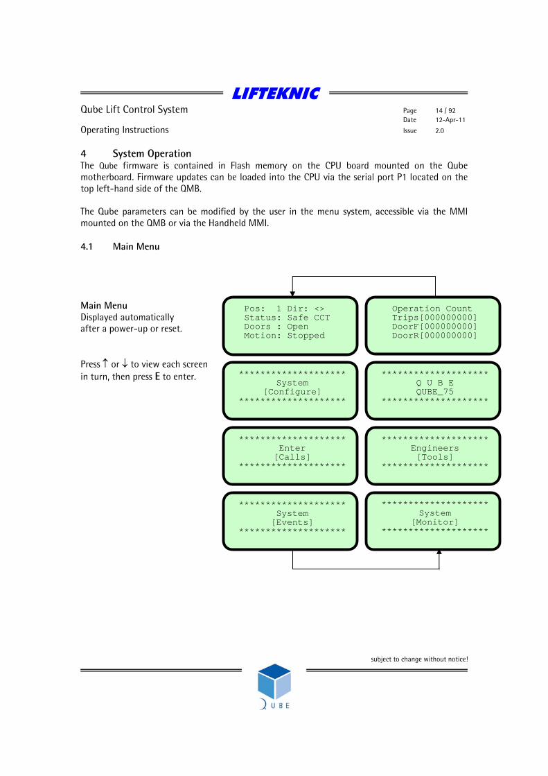
4 System Operation The Qube firmware is contained in Flash memory on the CPU board mounted on the Qube motherboard. Firmware updates can be loaded into the CPU via the serial port P1 located on the top left-hand side of the QMB. The Qube parameters can be modified by the user in the menu system, accessible via the MMI mounted on the QMB or via the Handheld MMI. 4.1 Main Menu Main Menu Displayed automatically after a power-up or reset. Press ↑ or ↓ to view each screen in turn, then press E to enter.
********************System
[Configure] ********************
********************Enter [Calls]
********************
********************System
[Monitor] ********************
********************Engineers [Tools]
********************
********************Q U B E QUBE_75
********************
Operation CountTrips[000000000] DoorF[000000000] DoorR[000000000]
Pos: 1 Dir: <> Status: Safe CCT Doors : Open Motion: Stopped
********************System [Events]
********************

LIFTEKNIC
Qube Lift Control System Page 15 / 92 Date 12-Apr-11
Operating Instructions Issue 2.0
subject to change without notice!
4.2 Menu Options Main Screen Setting Summary
System Configure Timers Tim1 Hall Dwell
Tim2 Car Dwell
Tim3 Rev Dwell
Tim4 DJR Time
Tim5 Low Speed
Tim6 Re-level
Tim7 Nudge Time
Tim8 Pre-open
Tim9 Door Hold
Tim10 Stop Delay
Tim11 Retry Time
Tim12 Homing
Tim13 Brake Switch
Tim14 Car Light
Tim15 Door Protection
Tim16 Car Preference
Tim17 Star Delta
Tim18 MG Shutdown
Tim19 MG DOL Time
Tim20 Zero Speed
Tim21 Brake Lift
Tim22 Brake Set
Tim23 Hyd Homing
Tim24 Sec Homing
Tim25 Idle Time
Tim26 Close Limit
Contract See Table in Section ??
Speeds PSE Resolution
Handwind Speed Limit
SMU Percentage
Contract Speed
Door Zone Speed

LIFTEKNIC
Qube Lift Control System Page 16 / 92 Date 12-Apr-11
Operating Instructions Issue 2.0
subject to change without notice!
Time & Date Set Time
Set Date
View Time & Date
Call Maps Config Blank Floors - Front
Config Trigger Strategy - Car Front
Config Trigger Strategy - Up Call Front
Config Trigger Strategy - Dn Call Front
Config Blank Floors - Rear
Config Trigger Strategy - Car Rear
Config Trigger Strategy - Up Call Rear
Config Trigger Strategy - Dn Call Rear
Save Config Save All Settings
Enter Calls Front Car Call
Front Hall Up Call
Front Hall Down Call
Rear Car Call
Rear Hall Up Call
Rear Hall Down Call
System Events View Log 100 Events Max.
Download Event Data
Download Parameters
Place Engineers Entry Stamp
Reset & Clear Event Table
Reset Operations Counters
System Monitor Front Call 1-16
Front Call 17-32
Rear Call 1-16
Rear Call 17-32
QMB Input State
I/O Block 1 Input State
I/O Block 2 Input State
I/O Block 3 Input State
I/O Block 4 Input State
I/O Block 5 Input State
I/O Block 6 Input State

LIFTEKNIC
Qube Lift Control System Page 17 / 92 Date 12-Apr-11
Operating Instructions Issue 2.0
subject to change without notice!
QMB Output State
I/O Block 1 Output State
I/O Block 2 Output State
I/O Block 3 Output State
I/O Block 4 Output State
I/O Block 5 Output State
I/O Block 6 Output State
Front Door Status
Rear Door Status
PSE System Status
Network 1 Status
Network 2 Status
Network 3 Status
Engineers Tools Prepare to Test ON/OFF
Door Disable ON/OFF
Overtravel Test ON/OFF
Auto Run Lift ON/OFF
Direct to Floor Disable ON/OFF
Speech Disable ON/OFF
WS By-pass ON/OFF
WS Overload ON/OFF
Test Event Logging ON/OFF
Software Version e.g. Qube 75
Operation Counter Journney Counter
Front Door Counter
Rear Door Counter

LIFTEKNIC
Qube Lift Control System Page 18 / 92 Date 12-Apr-11
Operating Instructions Issue 2.0
subject to change without notice!
4.3 Status Display This display provides useful data for the Engineer when working on the system. a) Position - Indicates the current position status of the control system
• Pos:16 - Current lift position (Single-high speed system only) • S:16 - Current lift position (Multi-high speed system only) • A:18 - Advanced lift position (Multi-high speed system only)
The advanced lift position is used to look ahead for calls and for slowdown point on higher speed (i.e. typically, speed>1.6m/s) lift systems (Note A & S positions will be equal when lift is levelling or stopped)
b) Direction - Indicates the current direction status of the control system
• Dir: <> - No direction • Dir: Up (Dn) - Committed direction of travel, lift stationary • Dir: >Up> (<Dn<) - Committed direction of traveI, lift in motion
c) Status - Indicates the current operating mode of the control system
• Automatic - Lift is operating in normal service (accepts all calls) • Inspection - Lift is operating under car top test control • Panel Test - Lift is operating under panel test control
(local inspection mode) • Special Sv - Lift is operating under service control (car preference) • Disable Dr - Automatic door control is disabled • Safety CCT - The primary safety circuit is broken (e.g. limits, stop push, etc.. ) • Fire Srv.1 - Lift being recalled under fire control
(e.g. firefighting, alarm, etc.. ) • Fire Srv.2 - Lift is operating under fire control • Shutdown - Lift has shutdown due to non-resettable fault
(manual reset req’d)
Pos: 1 Dir: <> Status: Safe CCT Doors : Open Motion: Stopped

LIFTEKNIC
Qube Lift Control System Page 19 / 92 Date 12-Apr-11
Operating Instructions Issue 2.0
subject to change without notice!
d) Doors - Indicates the current status of door movement • Closed ][ - Doors are fully closed. (CL off AND OL on, AND GL on) • Closing >< - Doors are closing (command to close until closed) • Opening <> - Doors are opening (command to open until open) • Open [ ] - Doors are fully open. (CL on AND OL off AND GL off).
e) Motion - Indicates the current status of the lift movement.
• Stopped - The lift is stationary at floor level. • Starting - The lift is starting to move away from floor level. • High Speed - The lift is travelling on high speed. • Slowing - The lift has been commanded to slowdown. • Levelling - The lift is in the levelling zone preparing to stop. • Stop Os DZ - The lift has stopped outside the door zone. • Car Diving - The lift is searching for a floor to reset the system position.
The status display will show a system event as it occurs. The event flashes on/off on the “Status:” line on the LCD display for 6 seconds, after which the display will revert to “Status:” once again. The event can be cleared immediately by pressing the E key.
Pressing and holding the E key whilst on the “Main Menu” screen displays a system summary screen. This screen shows some of the key configuration settings at a glance. Releasing the E key returns the “Main Menu” screen.
Lift: 1 Simplex Bot : 1 Top : 4 Park: 1 Fire: 1 Nets: 2 SSys: 3
LIFTEKNIC
Qube Lift Control System Page 20 / 92 Date 12-Apr-11
Operating Instructions Issue 2.0
subject to change without notice!
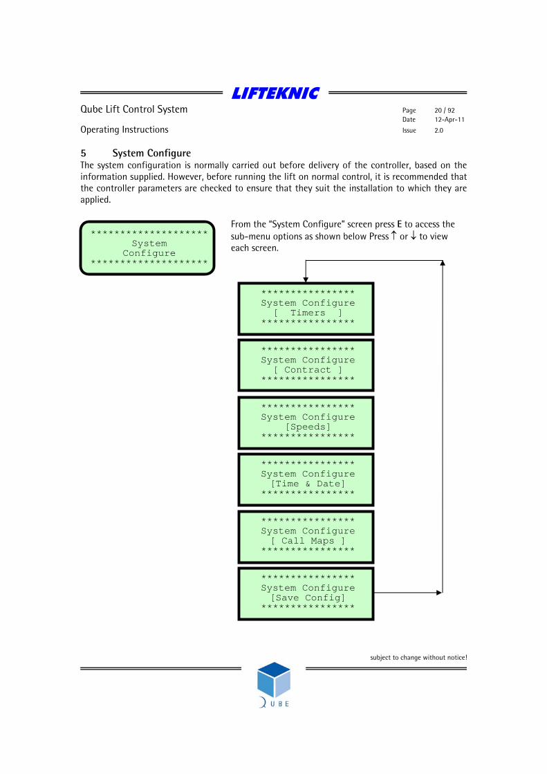
5 System Configure The system configuration is normally carried out before delivery of the controller, based on the information supplied. However, before running the lift on normal control, it is recommended that the controller parameters are checked to ensure that they suit the installation to which they are applied.
From the “System Configure” screen press E to access the sub-menu options as shown below Press ↑ or ↓ to view each screen.
**************** System Configure
[ Timers ] ****************
**************** System Configure [Time & Date]
****************
**************** System Configure [ Call Maps ]
****************
**************** System Configure
[ Contract ] ****************
******************** System
Configure ********************
**************** System Configure
[Speeds] ****************
**************** System Configure [Save Config]
****************

LIFTEKNIC
Qube Lift Control System Page 21 / 92 Date 12-Apr-11
Operating Instructions Issue 2.0
subject to change without notice!
5.1 System Configure [Timers]
From the [ Timers ] screen, press E to access each timer to view or change settings (see “Timer descriptions and settings table” for complete list).
Press ↑ or ↓ to view each timer
To change a timer setting press E
Press ↑ or ↓ to adjust the value
To accept the value press E
Press ↑ or ↓ to view next timer
To exit timer settings, press ←
**************** System Configure
[ Timers ] ****************
Tim1 Hall dwell * Unit:Second * * Value :6 * * New val:?? *
Tim1 Hall dwell * Unit:Second * * Value :6 * * New val:6 *
Tim1 Hall dwell * Unit:Second * * Value :6 * * New val:9 *
Tim1 Hall dwell * Unit:Second * * Value :9 * * New val:?? *
Tim2 Car dwell * Unit:Second * * Value :3 * * New val:?? *
**************** System Configure
[ Timers ] ****************

LIFTEKNIC
Qube Lift Control System Page 22 / 92 Date 12-Apr-11
Operating Instructions Issue 2.0
subject to change without notice!
Timer descriptions and settings table No. Name Description Def’lt Max. Min. Units
1 Hall dwell Landing call dwell timer Door open dwell time after the lift has answered a landing call.
6 30 3 Secs.
2 Car dwell Car call dwell timer Door open dwell time after the lift has answered a car call.
3 30 1 Secs.
3 Rev dwell
Differential dwell timer Door open dwell time after the doors have been re-opened by a door reversal device.
1 30 0 Secs.
4 DJR time
Motor run limit timer. Sets the time allowed for the lift to travel after the MC signal comes on. Timer is reset each time the lift changes position.
45 45 10 Secs.
5 Low speed Low speed limit timer Sets the time allowed for the lift to reach floor after a slowdown from high speed.
30 180 5 Secs.
6 Re-level Re-levelling limit timer. Sets the time allowed for the lift to re-level after the MC signal comes on.
10 20 4 Secs.
7 Nudge time
Door nudge timer Sets to time allowed for the doors to be continuously obstructed before nudging is initiated (if set).
20 30 3 Secs.
8 Pre-open
Pre-open delay timer. Sets the time between a valid door zone signal and a command to pre-open the doors.
4 40 1 Secs. /10
9 Door hold
Door hold open timer. Sets the time between activation of a door hold push or switch and automatic closing of the doors
60 3600 10 Secs.
10 Motor hold
Motor contactor hold timer. Sets the time between the stop signal and the un-conditional release of the motor contactors.
15 80 1 Secs. /10
11 Retry Time
Retry after fault timer Sets the time before the lift tries to automatically re-start after a retry type fault.
180 3600 60 Secs.
LIFTEKNIC
Qube Lift Control System Page 23 / 92 Date 12-Apr-11
Operating Instructions Issue 2.0
subject to change without notice!
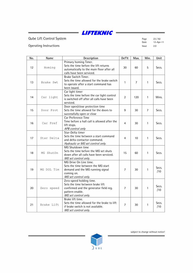
No. Name Description Def’lt Max. Min. Unit
12 Homing
Primary homing Timer. Sets the time before the lift returns automatically to the main floor after all calls have been serviced.
30 60 5 Secs.
13 Brake Swt
Brake Switch Timer. Sets the time allowed for the brake switch to operate after a start command has been issued.
1 7 1 Secs.
14 Car light
Car light timer Sets the time before the car light control is switched off after all calls have been serviced.
2 120 1 Mins.
15 Door Prot Door open/close protection time Sets the time allowed for the doors to successfully open or close
9 30 7 Secs.
16 Car Pref
Car Preference Time Time before a hall call is allowed after the lift stops. APB control only
4 30 1 Secs.
17 Star Delta
Star-Delta timer Sets the time between a start command and delta contactor command. Hydraulic or MG set control only.
4 10 1 Secs.
18 MG ShutDn
MG Shutdown time Sets the time before the MG set shuts down after all calls have been serviced. MG set control only.
15 60 1 Secs.
19 MG DOL Tim
MG Drive On Line time. Sets the time between the MG start demand and the MG running signal coming on. MG set control only.
7 30 1 Secs. /10
20 Zero speed
Zero-speed holding time. Sets the time between brake lift confirmed and the generator field reg. pattern enable. MG set control only.
7 30 1 Secs. /10
21 Brake Lift
Brake lift time. Sets the time allowed for the brake to lift if brake switch is not available. MG set control only.
7 30 1 Secs. /10

LIFTEKNIC
Qube Lift Control System Page 24 / 92 Date 12-Apr-11
Operating Instructions Issue 2.0
subject to change without notice!
No. Name Description Def’lt Max. Min. Unit
22 Brake Set
Brake set timer. Sets the time allowed for the brake to set if brake switch is not available. MG set control only.
7 30 1 Secs. /10
23 Hyd Home
Hydraulic dormant parking timer. Sets the time before the lift returns to the bottom level after all calls have been serviced. Hydraulic only.
15 15 1 Mins.
24 Sec Homing
Secondary homing Timer. Sets the time before the lift returns automatically to the main floor after all calls have been serviced and the primary homing floor has been serviced by another lift in the group. Duplex or group operation only
60 300 60 Secs.
25 Idle time Idle Time 1 5 1 Mins.
26 Close limit
Close limit overdrive timer. Sets the time between loss of door close limit breaking (Input DCL) and drop of door close signal (Output DCC). Typically required for Schindler QKS door operators
3 20 1 Secs. /10

LIFTEKNIC
Qube Lift Control System Page 25 / 92 Date 12-Apr-11
Operating Instructions Issue 2.0
subject to change without notice!
5.2 System Configure [Contract]
From the [ Contract ] screen, press E to access each parameter to view or change settings (see “Contract Parameter descriptions table” for complete list).
Press ↑ or ↓ to view parameters. Bottom line of display scrolls a short description of the parameter
To change parameter value press E
Press ↑ or ↓ to adjust the value
To accept the value press E
Press ↑ or ↓ for next parameter
To exit parameters, press ←
**************** System Configure
[ Contract ] ****************
>> TOP LEVEL <<**** Value:6 **** * Change Value ? * Highest floor level se
>> TOP LEVEL <<**** Value:6 **** * New Value:6 * served this value rese
>> TOP LEVEL <<**** Value:6 **** * New Value:8 * resets the selector wh
>> TOP LEVEL <<**** Value:8 **** * Change Value ? * when lift on top reset
>> BOTTOM LEVEL <<**** Value:1 **** * Change Value ? * Lowest floor level ser
**************** System Configure
[ Contract ] ****************
LIFTEKNIC
Qube Lift Control System Page 26 / 92 Date 12-Apr-11
Operating Instructions Issue 2.0
subject to change without notice!
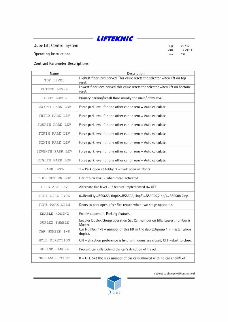
Contract Parameter Descriptions
Name Description
TOP LEVEL Highest floor level served. This value resets the selector when lift on top reset.
BOTTOM LEVEL Lowest floor level served this value resets the selector when lift on bottom reset.
LOBBY LEVEL Primary parking/recall floor usually the main/lobby level.
SECOND PARK LEV Force park level for one other car or zero = Auto calculate.
THIRD PARK LEV Force park level for one other car or zero = Auto calculate.
FOURTH PARK LEV Force park level for one other car or zero = Auto calculate.
FIFTH PARK LEV Force park level for one other car or zero = Auto calculate.
SIXTH PARK LEV Force park level for one other car or zero = Auto calculate.
SEVENTH PARK LEV Force park level for one other car or zero = Auto calculate.
EIGHTH PARK LEV Force park level for one other car or zero = Auto calculate.
PARK OPEN 1 = Park open at Lobby, 2 = Park open all floors.
FIRE RETURN LEV Fire return level – when recall activated.
FIRE ALT LEV Alternate fire level – if feature implemented 0= OFF.
FIRE CTRL TYPE 0=Recall ly,=BS5655,1inp/2=BS5588,1inp/3=BS5655,2inp/4=BS5588,2inp.
FIRE PARK OPEN Doors to park open after Fire return when two stage operation.
ENABLE HOMING Enable automatic Parking feature.
DUPLEX ENABLE Enables Duplex/Group operation Set Car number on lifts, Lowest number is Master.
CAR NUMBER 1-8 Car Number 1-8 – number of this lift in the duplex/group 1 = master when duplex.
HOLD DIRECTION ON = direction preference is held until doors are closed, OFF =start to close.
BEHIND CANCEL Prevent car calls behind the car’s direction of travel.
NUISANCE COUNT 0 = OFF, Set the max number of car calls allowed with no car entry/exit.
LIFTEKNIC
Qube Lift Control System Page 27 / 92 Date 12-Apr-11
Operating Instructions Issue 2.0
subject to change without notice!
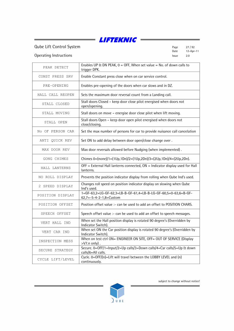
PEAK DETECT Enables UP & DN PEAK, 0 = OFF, When set value = No. of down calls to trigger DPK.
CONST PRESS SRV Enable Constant press close when on car service control.
PRE-OPENING Enables pre-opening of the doors when car slows and in DZ.
HALL CALL REOPEN Sets the maximum door reversal count from a Landing call.
STALL CLOSED Stall doors Closed – keep door close pilot energised when doors not open/opening.
STALL MOVING Stall doors on move – energise door close pilot when lift moving.
STALL OPEN Stall doors Open – keep door open pilot energised when doors not close/closing.
No OF PERSON CAR Set the max number of persons for car to provide nuisance call cancelation
ANTI QUICK REV Set ON to add delay between door open/close change over .
MAX DOOR REV Max door reversals allowed before Nudging (when implemented) .
GONG CHIMES Chimes 0=(none)/1=(1Up,1Dn)/2=(1Up,2Dn)/3=(2Up,1Dn)/4=(2Up,2Dn).
HALL LANTERNS OFF = External Hall lanterns connected, ON = Indicator display used for Hall lanterns.
NO ROLL DISPLAY Prevents the position indicator display from rolling when Qube Ind’s used.
2 SPEED DISPLAY Changes roll speed on position indicator display on slowing when Qube Ind’s used.
POSITION DISPLAY 1=GF-63,2=LG-GF-62,3=LB-B-GF-61,4=LB-B-LG-GF-60,5=0-63,6=B-GF-62,7=-5-4-2-1,8=Custom
POSITION OFFSET Position offset value :- can be used to add an offset to POSITION CHARS.
SPEECH OFFSET Speech offset value :- can be used to add an offset to speech messages.
VERT HALL IND When set the Hall position display is rotated 90 degree’s (Overridden by Indicator Switch).
VERT CAR IND When set ON the Car position display is rotated 90 degree’s (Overridden by Indicator Switch).
INSPECTION MESS When on test ctrl ON= ENGINEER ON SITE, OFF= OUT OF SERVICE (Display >V7.n only) .
SECURE STRATEGY Secure. 0=OFF/1=Input/2=Up calls/3=Down calls/4=Car calls/5=Up & down calls/6=All calls.
CYCLE LIFT/LEVEL Cycle. 0=OFF/(n)=Lift will travel between the LOBBY LEVEL and (n) continuously.
LIFTEKNIC
Qube Lift Control System Page 28 / 92 Date 12-Apr-11
Operating Instructions Issue 2.0
subject to change without notice!
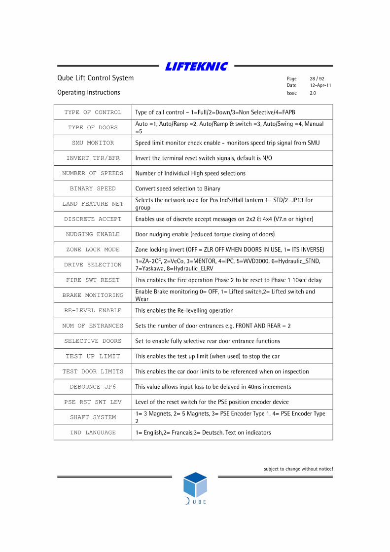
TYPE OF CONTROL Type of call control – 1=Full/2=Down/3=Non Selective/4=FAPB
TYPE OF DOORS Auto =1, Auto/Ramp =2, Auto/Ramp & switch =3, Auto/Swing =4, Manual =5
SMU MONITOR Speed limit monitor check enable - monitors speed trip signal from SMU
INVERT TFR/BFR Invert the terminal reset switch signals, default is N/O
NUMBER OF SPEEDS Number of Individual High speed selections
BINARY SPEED Convert speed selection to Binary
LAND FEATURE NET Selects the network used for Pos Ind's/Hall lantern 1= STD/2=JP13 for group
DISCRETE ACCEPT Enables use of discrete accept messages on 2x2 & 4x4 (V7.n or higher)
NUDGING ENABLE Door nudging enable (reduced torque closing of doors)
ZONE LOCK MODE Zone locking invert (OFF = ZLR OFF WHEN DOORS IN USE, 1= ITS INVERSE)
DRIVE SELECTION 1=ZA-2CF, 2=VeCo, 3=MENTOR, 4=IPC, 5=WVD3000, 6=Hydraulic_STND, 7=Yaskawa, 8=Hydraulic_ELRV
FIRE SWT RESET This enables the Fire operation Phase 2 to be reset to Phase 1 10sec delay
BRAKE MONITORING Enable Brake monitoring 0= OFF, 1= Lifted switch,2= Lifted switch and Wear
RE-LEVEL ENABLE This enables the Re-levelling operation
NUM OF ENTRANCES Sets the number of door entrances e.g. FRONT AND REAR = 2
SELECTIVE DOORS Set to enable fully selective rear door entrance functions
TEST UP LIMIT This enables the test up limit (when used) to stop the car
TEST DOOR LIMITS This enables the car door limits to be referenced when on inspection
DEBOUNCE JP6 This value allows input loss to be delayed in 40ms increments
PSE RST SWT LEV Level of the reset switch for the PSE position encoder device
SHAFT SYSTEM 1= 3 Magnets, 2= 5 Magnets, 3= PSE Encoder Type 1, 4= PSE Encoder Type 2
IND LANGUAGE 1= English,2= Francais,3= Deutsch. Text on indicators
LIFTEKNIC
Qube Lift Control System Page 29 / 92 Date 12-Apr-11
Operating Instructions Issue 2.0
subject to change without notice!
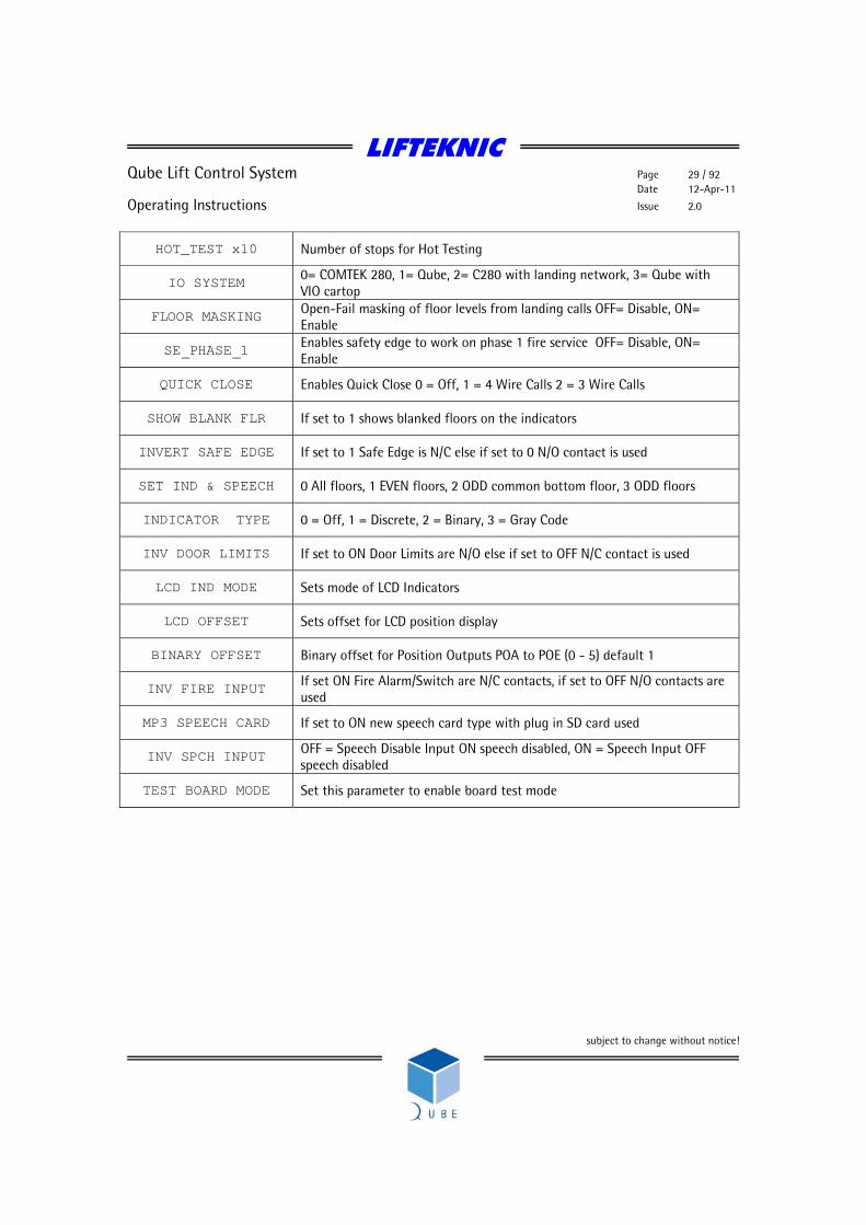
HOT_TEST x10 Number of stops for Hot Testing
IO SYSTEM 0= COMTEK 280, 1= Qube, 2= C280 with landing network, 3= Qube with VIO cartop
FLOOR MASKING Open-Fail masking of floor levels from landing calls OFF= Disable, ON= Enable
SE_PHASE_1 Enables safety edge to work on phase 1 fire service OFF= Disable, ON= Enable
QUICK CLOSE Enables Quick Close 0 = Off, 1 = 4 Wire Calls 2 = 3 Wire Calls
SHOW BLANK FLR If set to 1 shows blanked floors on the indicators
INVERT SAFE EDGE If set to 1 Safe Edge is N/C else if set to 0 N/O contact is used
SET IND & SPEECH 0 All floors, 1 EVEN floors, 2 ODD common bottom floor, 3 ODD floors
INDICATOR TYPE 0 = Off, 1 = Discrete, 2 = Binary, 3 = Gray Code
INV DOOR LIMITS If set to ON Door Limits are N/O else if set to OFF N/C contact is used
LCD IND MODE Sets mode of LCD Indicators
LCD OFFSET Sets offset for LCD position display
BINARY OFFSET Binary offset for Position Outputs POA to POE (0 - 5) default 1
INV FIRE INPUT If set ON Fire Alarm/Switch are N/C contacts, if set to OFF N/O contacts are used
MP3 SPEECH CARD If set to ON new speech card type with plug in SD card used
INV SPCH INPUT OFF = Speech Disable Input ON speech disabled, ON = Speech Input OFF speech disabled
TEST BOARD MODE Set this parameter to enable board test mode
LIFTEKNIC
Qube Lift Control System Page 30 / 92 Date 12-Apr-11
Operating Instructions Issue 2.0
subject to change without notice!
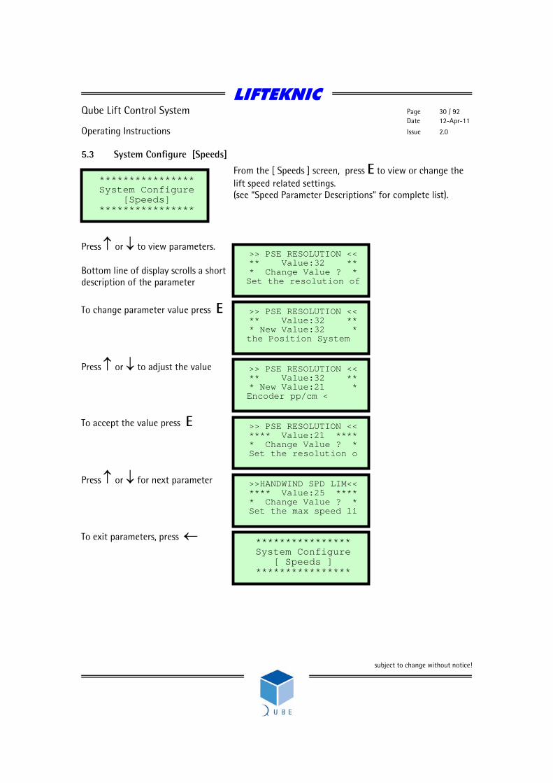
5.3 System Configure [Speeds]
From the [ Speeds ] screen, press E to view or change the lift speed related settings. (see “Speed Parameter Descriptions” for complete list).
Press ↑ or ↓ to view parameters. Bottom line of display scrolls a short description of the parameter
To change parameter value press E
Press ↑ or ↓ to adjust the value
To accept the value press E
Press ↑ or ↓ for next parameter
To exit parameters, press ←
**************** System Configure
[Speeds] ****************
>> PSE RESOLUTION <<** Value:32 ** * Change Value ? * Set the resolution of
>> PSE RESOLUTION <<** Value:32 ** * New Value:32 *
the Position System
>> PSE RESOLUTION <<** Value:32 ** * New Value:21 *
Encoder pp/cm <
>> PSE RESOLUTION <<**** Value:21 **** * Change Value ? * Set the resolution o
>>HANDWIND SPD LIM<<**** Value:25 **** * Change Value ? * Set the max speed li
**************** System Configure
[ Speeds ] ****************
LIFTEKNIC
Qube Lift Control System Page 31 / 92 Date 12-Apr-11
Operating Instructions Issue 2.0
subject to change without notice!
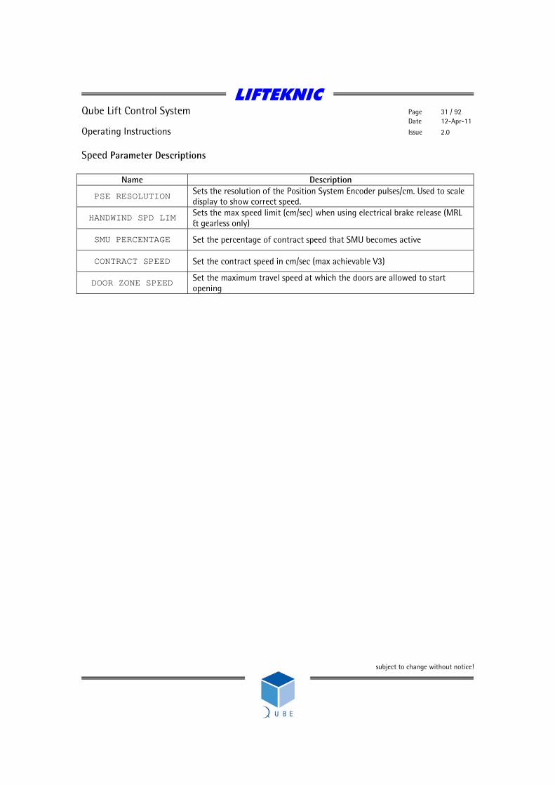
Speed Parameter Descriptions
Name Description
PSE RESOLUTION Sets the resolution of the Position System Encoder pulses/cm. Used to scale display to show correct speed.
HANDWIND SPD LIM Sets the max speed limit (cm/sec) when using electrical brake release (MRL & gearless only)
SMU PERCENTAGE Set the percentage of contract speed that SMU becomes active
CONTRACT SPEED Set the contract speed in cm/sec (max achievable V3)
DOOR ZONE SPEED Set the maximum travel speed at which the doors are allowed to start opening

LIFTEKNIC
Qube Lift Control System Page 32 / 92 Date 12-Apr-11
Operating Instructions Issue 2.0
subject to change without notice!
5.4 System Configure [Time & Date]
From the [ Time & Date ] screen, press E to view or change the time and date settings.
Press ↑ or ↓ to for options.
To change time or date, press E
To view current settings, press E
To exit parameters, press ←
**************** System Configure [Time & Date]
****************
**************** Set
[ Time ] ****************
**************** Set
[ Date ] ****************
**************** View
[ Time & Date ] ****************
* System date: * * * * 01/01/2000 * * 00:00:00 Hrs *
**************** Set
[ Time ] ****************

LIFTEKNIC
Qube Lift Control System Page 33 / 92 Date 12-Apr-11
Operating Instructions Issue 2.0
subject to change without notice!
5.5 System Configure [Call Maps]
From the [ Call Maps ] screen,
Press E to blank off a floor, or to secure / unsecure specific entrances in the building.
Press ↑ or ↓ to for options.
To exit Call Maps, press ←
**************** Configure
Trigger Strategy [ Car Front ]
**************** Configure
Trigger Strategy [ Dn call Front]
**************** Configure
Blank Floors [ Rear ]
**************** Configure
Trigger Strategy [ Up call Front]
**************** Configure
Trigger Strategy [ Dn call Front]
**************** Configure
Trigger Strategy [ Car Front ]
**************** System Configure [ Call Maps ]
****************
**************** Configure
Blank Floors [ Front ]
**************** Configure
Trigger Strategy [ Up call Front]

LIFTEKNIC
Qube Lift Control System Page 34 / 92 Date 12-Apr-11
Operating Instructions Issue 2.0
subject to change without notice!
When the lift serves front & rear entrances, the car & landing calls for any entrance not served by the lift should be blanked out using the “Blank Floors [Front]” & “Blank Floors [Rear]” functions.
To blank a front floor, press E
Press ↑ or ↓ to select floor
To blank the floor, press E
Note: Pressing E toggles the blank floor status between Allowed/Secured
Press ↑ or ↓ to select next floor
To exit, press ← Individual calls may be secured in a similar way by using the Trigger Strategy screens (shown on previous page). Once set up, these strategies can be implemented on an input (keyswitch, timeclock etc.,) to allow securing of specific calls by building security systems or by setting the “SECURE STRATEGY” parameter in “System Configure [Contract]”.
****************Configure
Blank Floors [ Front ]
Blank Floor Enable-disable ALL – Calls @
Level:1 Allowed
Blank Floor Enable-disable ALL – Calls @
Level:1 Secured
Blank Floor Enable-disable ALL – Calls @
Level:2 Allowed
**************** Configure
Blank Floors [ Front ]

LIFTEKNIC
Qube Lift Control System Page 35 / 92 Date 12-Apr-11
Operating Instructions Issue 2.0
subject to change without notice!
5.6 System Configure [Save Config]
From the [ Save Config ] screen, press E to save the current configuration.
To save settings, Press E
To confirm save, Press E Or press ← to exit
To exit, Press ←
**************** System Configure [Save Config]
****************
**************** Save New
Settings ? ****************
***************** Are you * * sure ? * No - - - - Yes
**************** Settings Saved!
****************
**************** System Configure [Save Config]
****************
**************** Please Wait
Burn in progress ****************

LIFTEKNIC
Qube Lift Control System Page 36 / 92 Date 12-Apr-11
Operating Instructions Issue 2.0
subject to change without notice!
6 Enter Calls When the lift is operating on Normal Control, it is possible to enter any “allowed” call via the keypad, described as follows. Checking the “System Monitor” will indicated which calls are allowed/secured.
From the “Enter Calls” screen press E to access the sub-menu options as shown below Press ↑ or ↓ to view each screen.
**************** Enter Calls
FRONT [ Car Call ]
**************** Enter Calls
REAR [ Car Call ]
**************** Enter Calls
REAR [ Hall Up Call ]
****************Enter Calls
FRONT [ Hall Up Call ]
******************** Enter
[Calls] ********************
**************** Enter Calls
FRONT [ Hall Dn Call ]
**************** Enter Calls
REAR [ Hall Dn Call ]

LIFTEKNIC
Qube Lift Control System Page 37 / 92 Date 12-Apr-11
Operating Instructions Issue 2.0
subject to change without notice!
6.1 Entering a Car Call Each of the “Enter Calls” functions work in the same way
To enter a front car call, press E
Press ↑ or ↓ to select floor
To enter call, press E Note: If call is accepted, “Done” is displayed but if the call is secured or the lift is not on Normal control, then “Failed” is displayed.
Press ↑ or ↓ to select next floor
To enter call, press E
To exit, press ←
**************** Enter Calls
FRONT [ Car Call ]
Ent Call at:2 Pos:1 Doors : Closed Stopped M/s 0.00
Ent Call at:2 Pos:1 Done Doors : Closed Stopped M/s 0.00
Ent Call at:4 Pos:2 Doors : Closed Stopped M/s 0.00
**************** Enter Calls
FRONT [ Car Call ]
Ent Call at:4 Pos:2 Failed Doors : Closed Stopped M/s 0.00

LIFTEKNIC
Qube Lift Control System Page 38 / 92 Date 12-Apr-11
Operating Instructions Issue 2.0
subject to change without notice!
7 System Events The Qube Micro has a large number of specific event messages, designed to give concise information about the operating history of the control system. The event messages provide information about the operating mode of the lift controller (e.g. Fire Control, Special Service etc..) and fault finding information in the event of a fault or failure. The event logger stores up to 100 events and when the event logger is full, a new event is stored and the oldest event drops out of the log.
To access the “System Events” screen, press ↓ or ↑ from the “Main Menu” screen, until the following screen appears.
Press E to enter the system event menu and use ↓ or ↑ to view the system event options. Accessing Event Logger Event Screen Detail EVENT TEXT No. – position of event in log Occur - number of occurrences of a given event since the log was last cleared. Date - dd/mm/yy Pos – actual position when event occurred Time - hh:mm:ss Adv - advance position when event occurred
Pressing E whilst a given event is displayed will show a line of help text that scrolls across the bottom of the screen.
Pressing E again will show the status of the QMB inputs/outputs at the instant of the event.
* System Events * ** View Log ** ** Total Events ** ** :100 **
****************** System Events ******************
PROCESSOR RESET No.015 Occur:001 02/07/03 Pos: 07 15:47:42 Adv: 07
LIFTEKNIC
Qube Lift Control System Page 39 / 92 Date 12-Apr-11
Operating Instructions Issue 2.0
subject to change without notice!
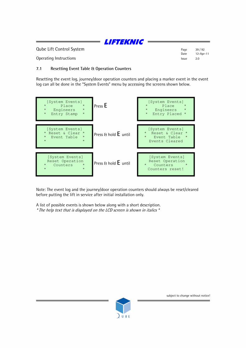
7.1 Resetting Event Table & Operation Counters Resetting the event log, journey/door operation counters and placing a marker event in the event log can all be done in the “System Events” menu by accessing the screens shown below.
Press E
Press & hold E until
Press & hold E until Note: The event log and the journey/door operation counters should always be reset/cleared before putting the lift in service after initial installation only. A list of possible events is shown below along with a short description. * The help text that is displayed on the LCD screen is shown in italics *
[System Events] * Place * * Engineers * * Entry Stamp *
[System Events] * Reset & Clear * * Event Table * Events Cleared
[System Events] Reset Operation
* Counters * * *
[System Events] * Place * * Engineers * * Entry Placed *
[System Events] * Reset & Clear * * Event Table * * *
[System Events] Reset Operation
* Counters * Counters reset!
LIFTEKNIC
Qube Lift Control System Page 40 / 92 Date 12-Apr-11
Operating Instructions Issue 2.0
subject to change without notice!
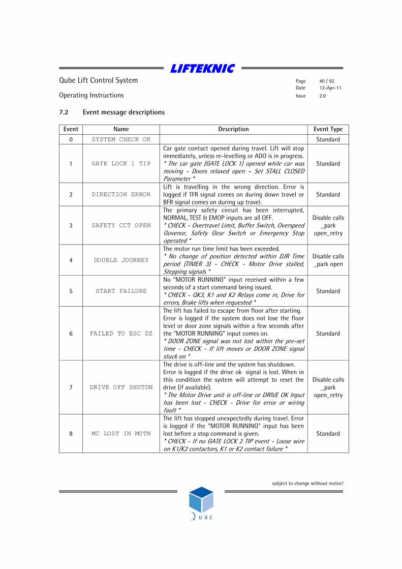
7.2 Event message descriptions
Event Name Description Event Type
0 SYSTEM CHECK OK Standard
1 GATE LOCK 1 TIP
Car gate contact opened during travel. Lift will stop immediately, unless re-levelling or ADO is in progress. * The car gate (GATE LOCK 1) opened while car was moving - Doors relaxed open – Set STALL CLOSED Parameter *
Standard
2 DIRECTION ERROR Lift is travelling in the wrong direction. Error is logged if TFR signal comes on during down travel or BFR signal comes on during up travel.
Standard
3 SAFETY CCT OPEN
The primary safety circuit has been interrupted, NORMAL, TEST & EMOP inputs are all OFF. * CHECK - Overtravel Limit, Buffer Switch, Overspeed Govenor, Safety Gear Switch or Emergency Stop operated *
Disable calls _park
open_retry
4 DOUBLE JOURNEY
The motor run time limit has been exceeded. * No change of position detected within DJR Time period (TIMER 3) - CHECK - Motor Drive stalled, Stepping signals *
Disable calls _park open
5 START FAILURE
No “MOTOR RUNNING” input received within a few seconds of a start command being issued. * CHECK - QK3, K1 and K2 Relays come in, Drive for errors, Brake lifts when requested *
Standard
6 FAILED TO ESC DZ
The lift has failed to escape from floor after starting. Error is logged if the system does not lose the floor level or door zone signals within a few seconds after the “MOTOR RUNNING” input comes on. * DOOR ZONE signal was not lost within the pre-set time - CHECK - If lift moves or DOOR ZONE signal stuck on *
Standard
7 DRIVE OFF SHUTDN
The drive is off-line and the system has shutdown. Error is logged if the drive ok signal is lost. When in this condition the system will attempt to reset the drive (if available). * The Motor Drive unit is off-line or DRIVE OK Input has been lost - CHECK - Drive for error or wiring fault *
Disable calls _park
open_retry
8 MC LOST IN MOTN
The lift has stopped unexpectedly during travel. Error is logged if the “MOTOR RUNNING” input has been lost before a stop command is given. * CHECK - If no GATE LOCK 2 TIP event - Loose wire on K1/K2 contactors, K1 or K2 contact failure *
Standard
LIFTEKNIC
Qube Lift Control System Page 41 / 92 Date 12-Apr-11
Operating Instructions Issue 2.0
subject to change without notice!
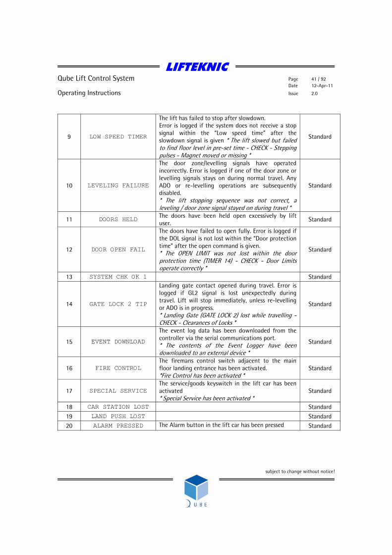
9 LOW SPEED TIMER
The lift has failed to stop after slowdown. Error is logged if the system does not receive a stop signal within the “Low speed time” after the slowdown signal is given * The lift slowed but failed to find floor level in pre-set time - CHECK - Stepping pulses - Magnet moved or missing *
Standard
10 LEVELING FAILURE
The door zone/levelling signals have operated incorrectly. Error is logged if one of the door zone or levelling signals stays on during normal travel. Any ADO or re-levelling operations are subsequently disabled. * The lift stopping sequence was not correct, a leveling / door zone signal stayed on during travel *
Standard
11 DOORS HELD The doors have been held open excessively by lift user.
Standard
12 DOOR OPEN FAIL
The doors have failed to open fully. Error is logged if the DOL signal is not lost within the “Door protection time” after the open command is given. * The OPEN LIMIT was not lost within the door protection time (TIMER 14) - CHECK - Door Limits operate correctly *
Standard
13 SYSTEM CHK OK 1 Standard
14 GATE LOCK 2 TIP
Landing gate contact opened during travel. Error is logged if GL2 signal is lost unexpectedly during travel. Lift will stop immediately, unless re-levelling or ADO is in progress. * Landing Gate (GATE LOCK 2) lost while travelling - CHECK - Clearances of Locks *
Standard
15 EVENT DOWNLOAD
The event log data has been downloaded from the controller via the serial communications port. * The contents of the Event Logger have been downloaded to an external device *
Standard
16 FIRE CONTROL The firemans control switch adjacent to the main floor landing entrance has been activated. *Fire Control has been activated *
Standard
17 SPECIAL SERVICE The service/goods keyswitch in the lift car has been activated * Special Service has been activated *
Standard
18 CAR STATION LOST Standard
19 LAND PUSH LOST Standard
20 ALARM PRESSED The Alarm button in the lift car has been pressed Standard
LIFTEKNIC
Qube Lift Control System Page 42 / 92 Date 12-Apr-11
Operating Instructions Issue 2.0
subject to change without notice!
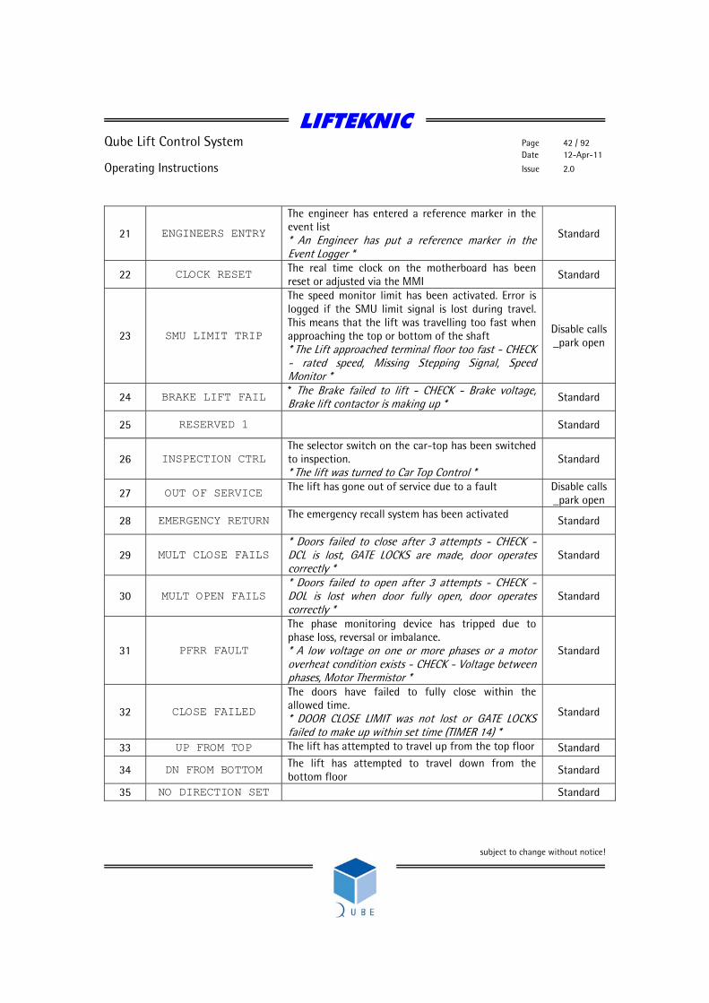
21 ENGINEERS ENTRY
The engineer has entered a reference marker in the event list * An Engineer has put a reference marker in the Event Logger *
Standard
22 CLOCK RESET The real time clock on the motherboard has been reset or adjusted via the MMI Standard
23 SMU LIMIT TRIP
The speed monitor limit has been activated. Error is logged if the SMU limit signal is lost during travel. This means that the lift was travelling too fast when approaching the top or bottom of the shaft * The Lift approached terminal floor too fast - CHECK - rated speed, Missing Stepping Signal, Speed Monitor *
Disable calls _park open
24 BRAKE LIFT FAIL * The Brake failed to lift - CHECK - Brake voltage, Brake lift contactor is making up * Standard
25 RESERVED 1 Standard
26 INSPECTION CTRL The selector switch on the car-top has been switched to inspection. * The lift was turned to Car Top Control *
Standard
27 OUT OF SERVICE The lift has gone out of service due to a fault
Disable calls _park open
28 EMERGENCY RETURN The emergency recall system has been activated
Standard
29 MULT CLOSE FAILS * Doors failed to close after 3 attempts - CHECK - DCL is lost, GATE LOCKS are made, door operates correctly *
Standard
30 MULT OPEN FAILS * Doors failed to open after 3 attempts - CHECK - DOL is lost when door fully open, door operates correctly *
Standard
31 PFRR FAULT
The phase monitoring device has tripped due to phase loss, reversal or imbalance. * A low voltage on one or more phases or a motor overheat condition exists - CHECK - Voltage between phases, Motor Thermistor *
Standard
32 CLOSE FAILED
The doors have failed to fully close within the allowed time. * DOOR CLOSE LIMIT was not lost or GATE LOCKS failed to make up within set time (TIMER 14) *
Standard
33 UP FROM TOP The lift has attempted to travel up from the top floor Standard
34 DN FROM BOTTOM The lift has attempted to travel down from the bottom floor Standard
35 NO DIRECTION SET Standard
LIFTEKNIC
Qube Lift Control System Page 43 / 92 Date 12-Apr-11
Operating Instructions Issue 2.0
subject to change without notice!
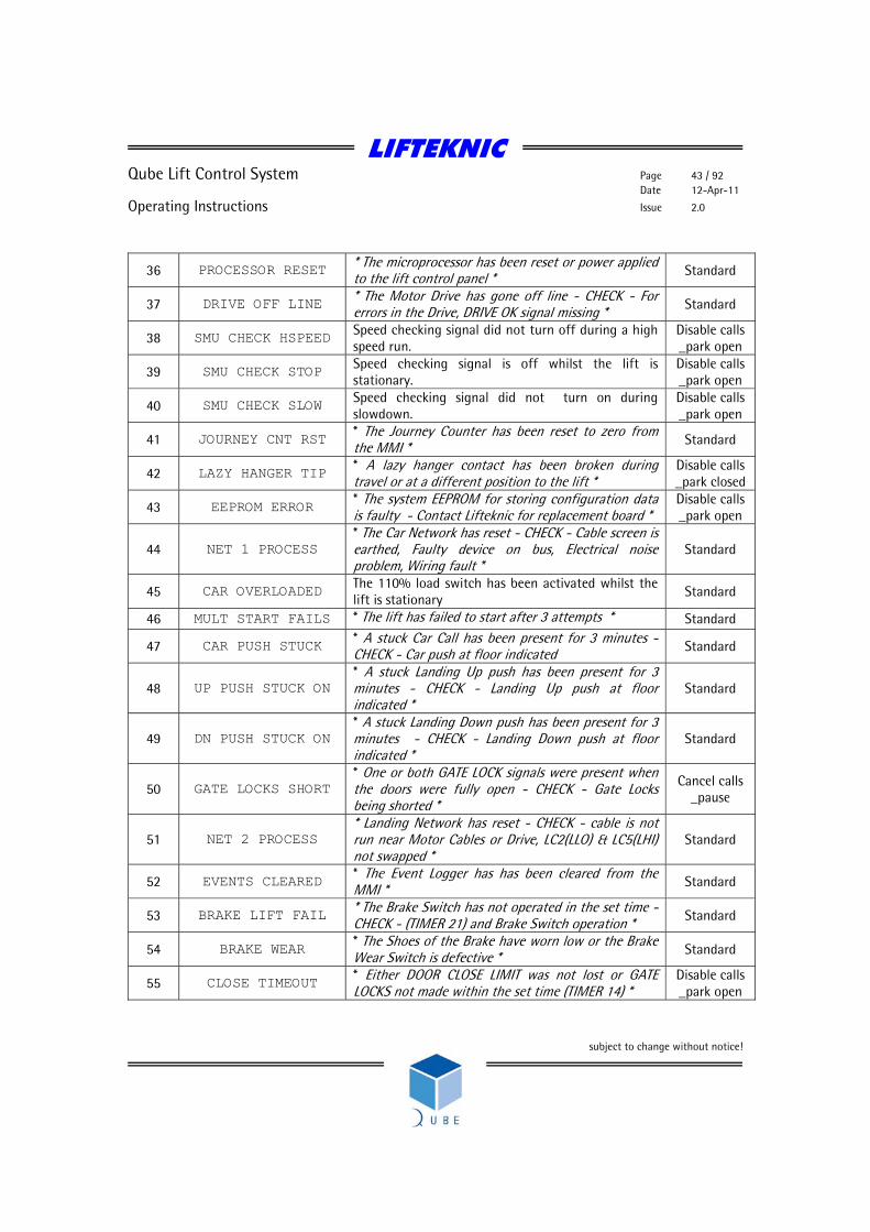
36 PROCESSOR RESET * The microprocessor has been reset or power applied to the lift control panel * Standard
37 DRIVE OFF LINE * The Motor Drive has gone off line - CHECK - For errors in the Drive, DRIVE OK signal missing * Standard
38 SMU CHECK HSPEED Speed checking signal did not turn off during a high speed run.
Disable calls _park open
39 SMU CHECK STOP Speed checking signal is off whilst the lift is stationary.
Disable calls _park open
40 SMU CHECK SLOW Speed checking signal did not turn on during slowdown.
Disable calls _park open
41 JOURNEY CNT RST * The Journey Counter has been reset to zero from the MMI * Standard
42 LAZY HANGER TIP * A lazy hanger contact has been broken during travel or at a different position to the lift *
Disable calls _park closed
43 EEPROM ERROR * The system EEPROM for storing configuration data is faulty - Contact Lifteknic for replacement board *
Disable calls _park open
44 NET 1 PROCESS * The Car Network has reset - CHECK - Cable screen is earthed, Faulty device on bus, Electrical noise problem, Wiring fault *
Standard
45 CAR OVERLOADED The 110% load switch has been activated whilst the lift is stationary Standard
46 MULT START FAILS * The lift has failed to start after 3 attempts * Standard
47 CAR PUSH STUCK * A stuck Car Call has been present for 3 minutes - CHECK - Car push at floor indicated Standard
48 UP PUSH STUCK ON * A stuck Landing Up push has been present for 3 minutes - CHECK - Landing Up push at floor indicated *
Standard
49 DN PUSH STUCK ON * A stuck Landing Down push has been present for 3 minutes - CHECK - Landing Down push at floor indicated *
Standard
50 GATE LOCKS SHORT * One or both GATE LOCK signals were present when the doors were fully open - CHECK - Gate Locks being shorted *
Cancel calls _pause
51 NET 2 PROCESS * Landing Network has reset - CHECK - cable is not run near Motor Cables or Drive, LC2(LLO) & LC5(LHI) not swapped *
Standard
52 EVENTS CLEARED * The Event Logger has has been cleared from the MMI * Standard
53 BRAKE LIFT FAIL * The Brake Switch has not operated in the set time - CHECK - (TIMER 21) and Brake Switch operation * Standard
54 BRAKE WEAR * The Shoes of the Brake have worn low or the Brake Wear Switch is defective * Standard
55 CLOSE TIMEOUT * Either DOOR CLOSE LIMIT was not lost or GATE LOCKS not made within the set time (TIMER 14) *
Disable calls _park open

LIFTEKNIC
Qube Lift Control System Page 44 / 92 Date 12-Apr-11
Operating Instructions Issue 2.0
subject to change without notice!
56 STOP OUTSIDE DZ * The lift has stopped outside of floor level or no Door Zone signal was present Standard
57 CONTACTOR STUCK * The Main Contactor has not dropped out before starting * Standard
58 BOT RESET SLOW
Bottom slowing limit has been reached without prior slowdown message from position system The Bottom Floor Reset reached before slowing commenced - CHECK - Stepping signals, Faulty Reset Switch *
Disable calls _park open
59 TOP RESET SLOW
Top slowing limit has been reached without prior slowdown message from position system * The Top Floor Reset reached before slowing commenced - CHECK - Stepping signals, Faulty Reset Switch *
Disable calls _park open
60 MULT BRAKE FAULT The brake has failed to lift after three successive attempts
Disable calls _park open
61 ZERO MOVEMENT No movement signal from drive has been detected after speed command issued
Cancel calls _pause
62 RAMP SWT FAULT * The door Retiring Ramp Switch was not detected when operated - CHECK - Ramp Voltage, wiring, Ramp coil *
Cancel calls _pause
63 EMOP CONTROL * The lift was switched to Emergency Operation * Standard
64 AUTO CONTROL * The lift was switched to Automatic Operation * Standard
65 PARAM DOWNLOAD * The System Parameters have been downloaded to an external device * Standard
66 MBX TRIGGERED Lift has slowed on a Music box (speed monitor/policing limit)
Disable calls _park open
69 OVERTRAVEL TRIP The Overtravel limit has been operated (Hydraulic only)
Disable calls _park open
70 ENGINEER ON SITE * An Engineer has logged on site via a keypad or lift switched to EMOP or Inspection * Standard
71 ENGINEER OFFSITE * An Engineer has logged off site via a keypad * Standard
72 1000 NEW STARTS * Lift has made 1000 starts since last occurrence of this event * Standard
73 2000 DOOR OPS F * Front doors have opened 2000 times since last occurrence of this event * Standard
74 2000 DOOR OPS R * Rear doors have opened 2000 times since last occurrence of this event * Standard
75 LIFT AVAILABLE * The Lift has returned to service after being Out of Service * Standard
76 LANDING LOCK 1
TIP * Landing Gate Lock at Floor 1 opened while the lift was at another floor * Standard
77 LANDING LOCK 2
TIP * Landing Gate Lock at Floor 2 opened while the lift was at another floor * Standard
78 LANDING LOCK 3 * Landing Gate Lock at Floor 3 opened while the lift Standard
LIFTEKNIC
Qube Lift Control System Page 45 / 92 Date 12-Apr-11
Operating Instructions Issue 2.0
subject to change without notice!
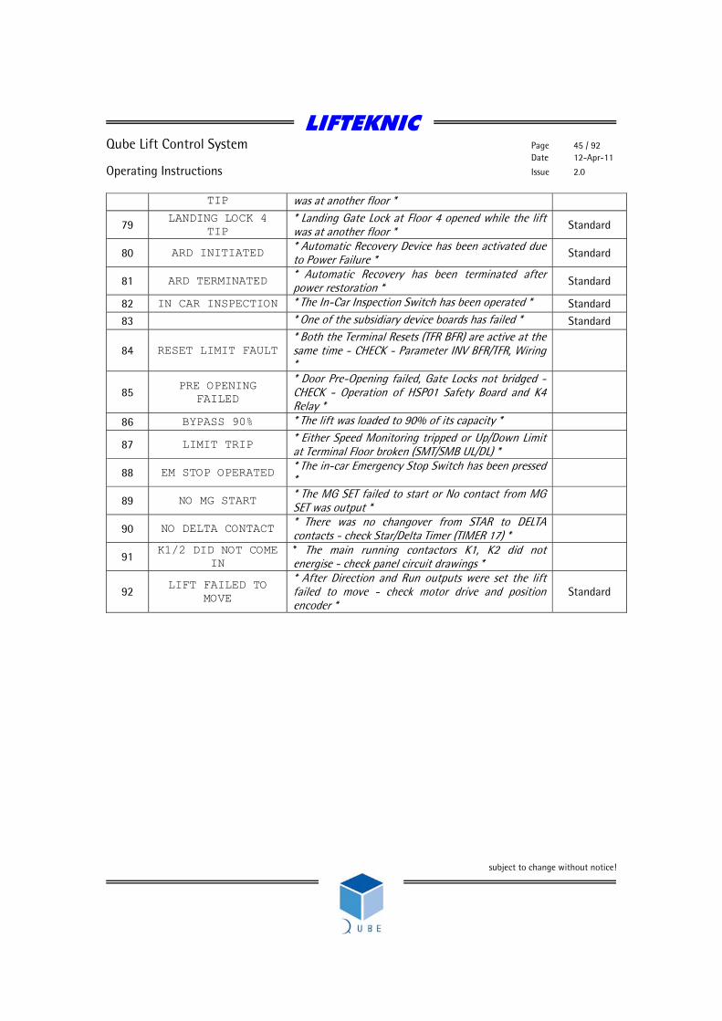
TIP was at another floor *
79 LANDING LOCK 4
TIP * Landing Gate Lock at Floor 4 opened while the lift was at another floor * Standard
80 ARD INITIATED * Automatic Recovery Device has been activated due to Power Failure * Standard
81 ARD TERMINATED * Automatic Recovery has been terminated after power restoration * Standard
82 IN CAR INSPECTION * The In-Car Inspection Switch has been operated * Standard
83 * One of the subsidiary device boards has failed * Standard
84 RESET LIMIT FAULT * Both the Terminal Resets (TFR BFR) are active at the same time - CHECK - Parameter INV BFR/TFR, Wiring *
85 PRE OPENING
FAILED
* Door Pre-Opening failed, Gate Locks not bridged - CHECK - Operation of HSP01 Safety Board and K4 Relay *
86 BYPASS 90% * The lift was loaded to 90% of its capacity *
87 LIMIT TRIP * Either Speed Monitoring tripped or Up/Down Limit at Terminal Floor broken (SMT/SMB UL/DL) *
88 EM STOP OPERATED * The in-car Emergency Stop Switch has been pressed *
89 NO MG START * The MG SET failed to start or No contact from MG SET was output *
90 NO DELTA CONTACT * There was no changover from STAR to DELTA contacts - check Star/Delta Timer (TIMER 17) *
91 K1/2 DID NOT COME
IN * The main running contactors K1, K2 did not energise - check panel circuit drawings *
92 LIFT FAILED TO
MOVE
* After Direction and Run outputs were set the lift failed to move - check motor drive and position encoder *
Standard
LIFTEKNIC
Qube Lift Control System Page 46 / 92 Date 12-Apr-11
Operating Instructions Issue 2.0
subject to change without notice!
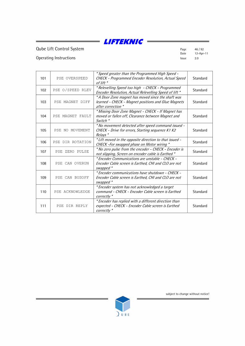
101 PSE OVERSPEED * Speed greater than the Programmed High Speed - CHECK - Programmed Encoder Resolution, Actual Speed of lift *
Standard
102 PSE O/SPEED RLEV * Relevelling Speed too high - CHECK - Programmed Encoder Resolution, Actual Relevelling Speed of lift * Standard
103 PSE MAGNET DIFF * A Door Zone magnet has moved since the shaft was learned - CHECK - Magnet positions and Glue Magnets after correction *
Standard
104 PSE MAGNET FAULT * Missing Door Zone Magnet - CHECK - If Magnet has moved or fallen off, Clearance between Magnet and Switch *
Standard
105 PSE NO MOVEMENT * No movement detected after speed command issued - CHECK - Drive for errors, Starting sequence K1 K2 Relays *
Standard
106 PSE DIR ROTATION * Lift moved in the opposite direction to that issued - CHECK -For swapped phase on Motor wiring * Standard
107 PSE ZERO PULSE * No zero pulse from the encoder - CHECK - Encoder is not slipping, Screen on encoder cable is Earthed * Standard
108 PSE CAN OVERUN * Encoder Communications are unstable - CHECK - Encoder Cable screen is Earthed, CHI and CLO are not swapped *
Standard
109 PSE CAN BUSOFF * Encoder communications have shutdown - CHECK - Encoder Cable screen is Earthed, CHI and CLO are not swapped *
Standard
110 PSE ACKNOWLEDGE * Encoder system has not acknowledged a target command - CHECK - Encoder Cable screen is Earthed correctly *
Standard
111 PSE DIR REPLY * Encoder has replied with a different direction than expected - CHECK - Encoder Cable screen is Earthed correctly *
Standard
LIFTEKNIC
Qube Lift Control System Page 47 / 92 Date 12-Apr-11
Operating Instructions Issue 2.0
subject to change without notice!
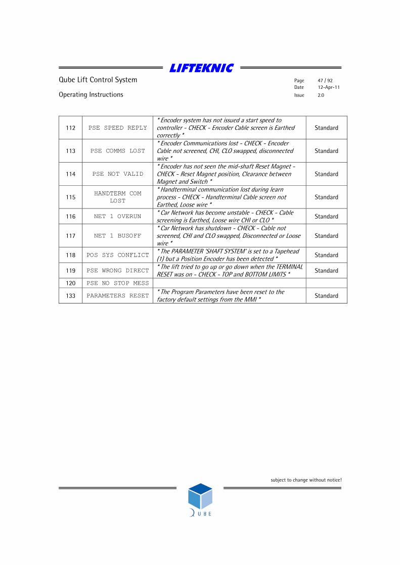
112 PSE SPEED REPLY * Encoder system has not issued a start speed to controller - CHECK - Encoder Cable screen is Earthed correctly *
Standard
113 PSE COMMS LOST * Encoder Communications lost - CHECK - Encoder Cable not screened, CHI, CLO swapped, disconnected wire *
Standard
114 PSE NOT VALID * Encoder has not seen the mid-shaft Reset Magnet - CHECK - Reset Magnet position, Clearance between Magnet and Switch *
Standard
115 HANDTERM COM
LOST
* Handterminal communication lost during learn process - CHECK - Handterminal Cable screen not Earthed, Loose wire *
Standard
116 NET 1 OVERUN * Car Network has become unstable - CHECK - Cable screening is Earthed, Loose wire CHI or CLO * Standard
117 NET 1 BUSOFF * Car Network has shutdown - CHECK - Cable not screened, CHI and CLO swapped, Disconnected or Loose wire *
Standard
118 POS SYS CONFLICT * The PARAMETER 'SHAFT SYSTEM' is set to a Tapehead (1) but a Position Encoder has been detected * Standard
119 PSE WRONG DIRECT * The lift tried to go up or go down when the TERMINAL RESET was on - CHECK - TOP and BOTTOM LIMITS * Standard
120 PSE NO STOP MESS
133 PARAMETERS RESET * The Program Parameters have been reset to the factory default settings from the MMI * Standard
LIFTEKNIC
Qube Lift Control System Page 48 / 92 Date 12-Apr-11
Operating Instructions Issue 2.0
subject to change without notice!
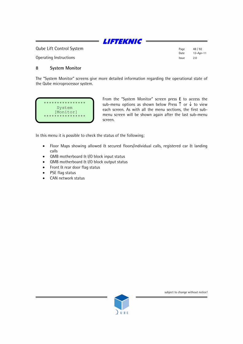
8 System Monitor The “System Monitor” screens give more detailed information regarding the operational state of the Qube microprocessor system.
From the “System Monitor” screen press E to access the sub-menu options as shown below Press ↑ or ↓ to view each screen. As with all the menu sections, the first sub-menu screen will be shown again after the last sub-menu screen.
In this menu it is possible to check the status of the following;
• Floor Maps showing allowed & secured floors/individual calls, registered car & landing calls
• QMB motherboard & I/O block input status • QMB motherboard & I/O block output status • Front & rear door flag status • PSE flag status • CAN network status
**************** System [Monitor] ****************
LIFTEKNIC
Qube Lift Control System Page 49 / 92 Date 12-Apr-11
Operating Instructions Issue 2.0
subject to change without notice!
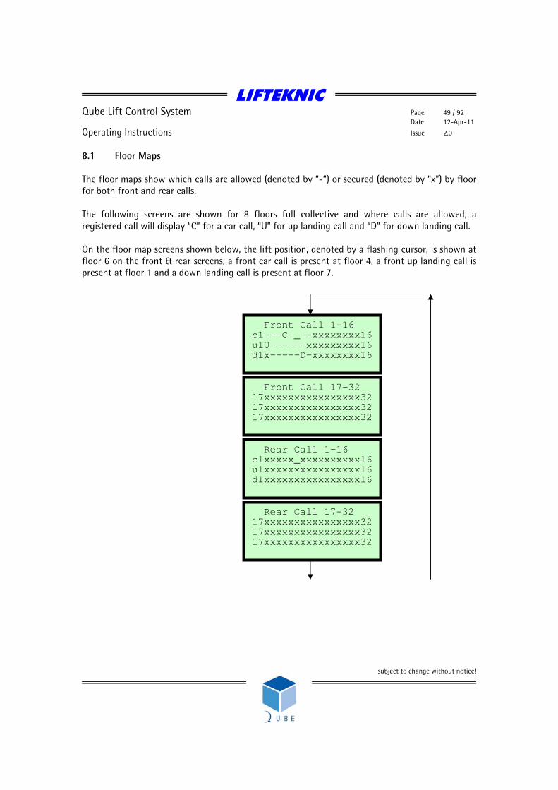
8.1 Floor Maps The floor maps show which calls are allowed (denoted by “-“) or secured (denoted by “x”) by floor for both front and rear calls. The following screens are shown for 8 floors full collective and where calls are allowed, a registered call will display “C” for a car call, “U” for up landing call and “D” for down landing call. On the floor map screens shown below, the lift position, denoted by a flashing cursor, is shown at floor 6 on the front & rear screens, a front car call is present at floor 4, a front up landing call is present at floor 1 and a down landing call is present at floor 7.
Rear Call 17-32 17xxxxxxxxxxxxxxxx32 17xxxxxxxxxxxxxxxx32 17xxxxxxxxxxxxxxxx32
Rear Call 1-16 c1xxxxx_xxxxxxxxxx16 u1xxxxxxxxxxxxxxxx16 d1xxxxxxxxxxxxxxxx16
Front Call 17-32 17xxxxxxxxxxxxxxxx32 17xxxxxxxxxxxxxxxx32 17xxxxxxxxxxxxxxxx32
Front Call 1-16 c1---C-_--xxxxxxxx16 u1U------xxxxxxxxx16 d1x-----D-xxxxxxxx16

LIFTEKNIC
Qube Lift Control System Page 50 / 92 Date 12-Apr-11
Operating Instructions Issue 2.0
subject to change without notice!
8.2 QMB Motherboard & I/O Block Input Status The input status blocks show whether or not that the Qube microprocessor has correctly read and processed the system inputs. The QMB input state screen shows the motherboard input status, where the JP6 shows IN1-IN8, JP8 shows IN9-IN16 and JP4 shows IN17-IN24. However, in each case the inputs should be read from right to left. Each I/O Block screen represents the input status of each of the I/O boards attached to one of the expansion node boards, usually addressed as node 1 - 6. The RIO/LIO car interface is always addressed as node 1, other functions have different addresses (see RIO Interface section for details). On the I/O Block screen, the boards are represented as shown above, and as with the motherboard screen, the inputs for each board block should be read from right to left. When the input status screens are used in conjunction with the LED’s mounted adjacent to each of the input terminal, it is possible to determine whether the software is correctly responding to the hardware state.
QMB Input state JP6[11000101] JP8[11000000] JP4[11110000]
I/O Block 1 RIO/LIO Inputs [00000000][00000000] [00000000][00000000]
I/O Block 2 Input state [00000000][00000000] [00000000][00000000]
I/O Block 6 Input state [00000000][00000000] [00000000][00000000]
IN1
IN24
I/O board 2
I/O board 4
I/O board 1
I/O board 3
Same for I/O blocks 3-5
LIFTEKNIC
Qube Lift Control System Page 51 / 92 Date 12-Apr-11
Operating Instructions Issue 2.0
subject to change without notice!
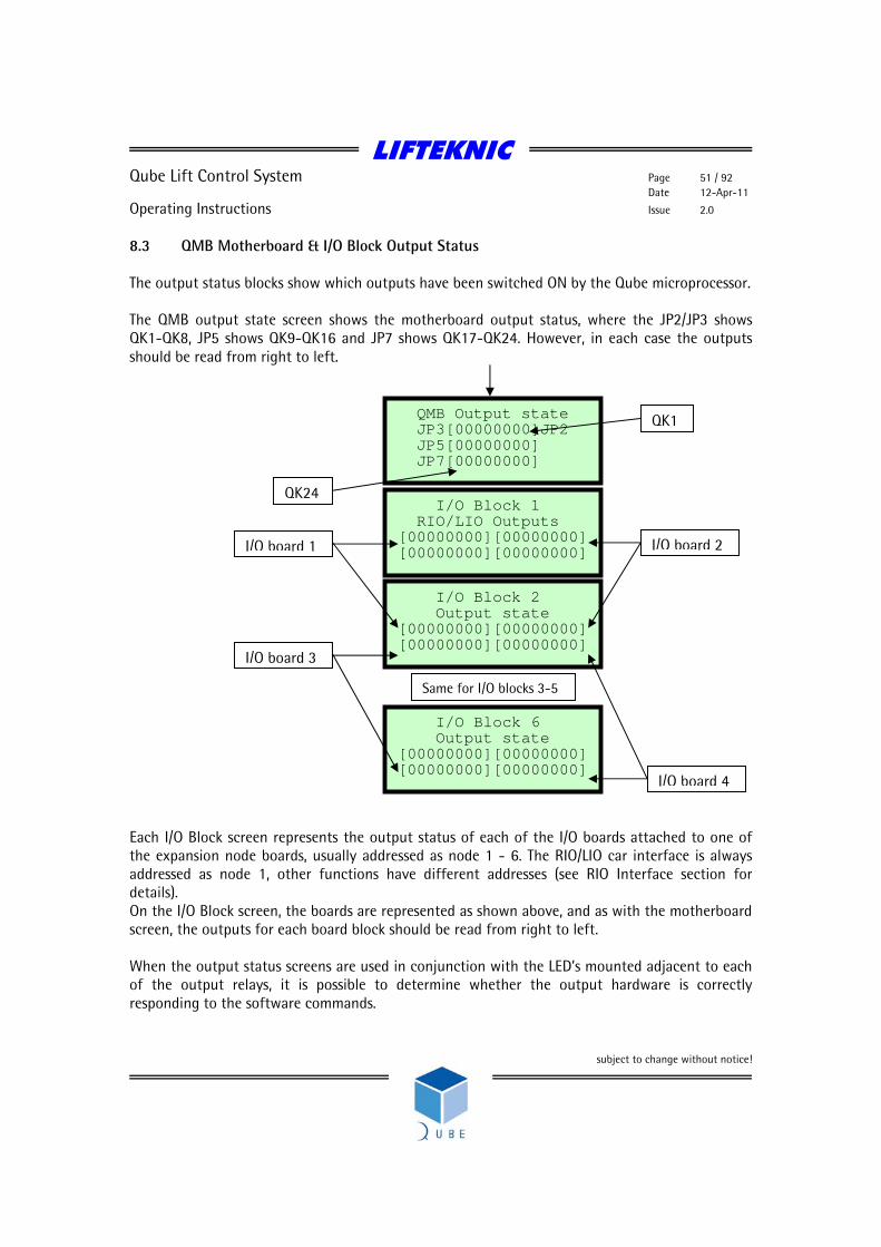
8.3 QMB Motherboard & I/O Block Output Status The output status blocks show which outputs have been switched ON by the Qube microprocessor. The QMB output state screen shows the motherboard output status, where the JP2/JP3 shows QK1-QK8, JP5 shows QK9-QK16 and JP7 shows QK17-QK24. However, in each case the outputs should be read from right to left. Each I/O Block screen represents the output status of each of the I/O boards attached to one of the expansion node boards, usually addressed as node 1 - 6. The RIO/LIO car interface is always addressed as node 1, other functions have different addresses (see RIO Interface section for details). On the I/O Block screen, the boards are represented as shown above, and as with the motherboard screen, the outputs for each board block should be read from right to left. When the output status screens are used in conjunction with the LED’s mounted adjacent to each of the output relays, it is possible to determine whether the output hardware is correctly responding to the software commands.
QMB Output state JP3[00000000]JP2
JP5[00000000] JP7[00000000]
I/O Block 1 RIO/LIO Outputs [00000000][00000000] [00000000][00000000]
I/O Block 2 Output state [00000000][00000000] [00000000][00000000]
I/O Block 6 Output state [00000000][00000000] [00000000][00000000]
QK1
QK24
I/O board 2
I/O board 4
I/O board 1
I/O board 3
Same for I/O blocks 3-5

LIFTEKNIC
Qube Lift Control System Page 52 / 92 Date 12-Apr-11
Operating Instructions Issue 2.0
subject to change without notice!
8.4 Door Flag Status The door status screens confirm which of the door related inputs, outputs & parameters have been activated. Door 1 screen shows front door status & Door 2 screen shows rear door status, although some of the signals are common to both doors. Signal Description dd/DD Door Disable Parameter in Engineers Tools menu rr/RR Retiring Ramp Output rs/RS Ramp Switch Input dop/DOP Door Open Push Input dcp/DCP Door Close Push Input se/SE Safety Edge Input bb/BB Broken Beam Input dor/DOR Open Door Output dcr/DCR Close Door Output dol/DOL Door Open Limit Input dcl/DCL Door Close Limit Input dst/DST Down Slow/Stop Input ust/UST Up Slow/Stop Input dz/DZ Door Zone Input ado/ADO Pre-open Doors Parameter in System Configure [Contract] menu
Door1 dd rr rs dop dcp se bb
dor dcr dol dcl DST UST DZ ADO
Door2 dd rr rs dop dcp se bb
dor dcr dol dcl DST UST DZ ADO
Lower case shows that signal is “off”
Upper case shows that signal is “ON”
LIFTEKNIC
Qube Lift Control System Page 53 / 92 Date 12-Apr-11
Operating Instructions Issue 2.0
subject to change without notice!
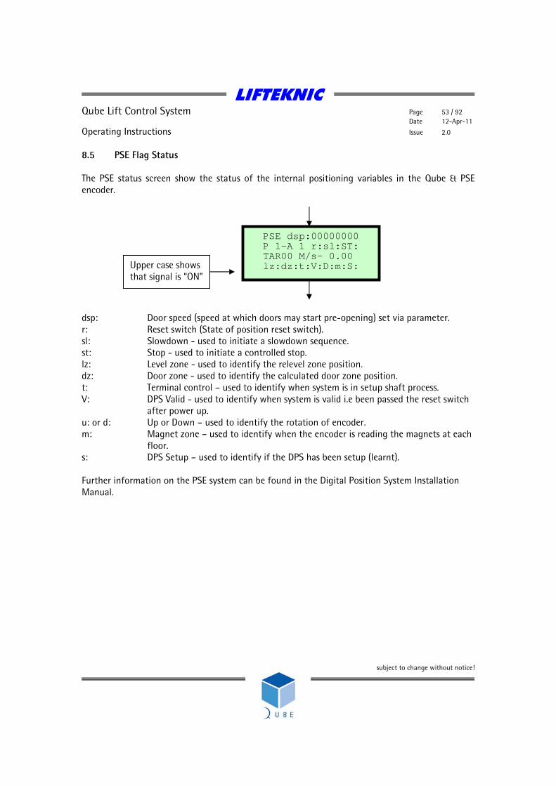
8.5 PSE Flag Status The PSE status screen show the status of the internal positioning variables in the Qube & PSE encoder. dsp: Door speed (speed at which doors may start pre-opening) set via parameter. r: Reset switch (State of position reset switch). sl: Slowdown - used to initiate a slowdown sequence. st: Stop - used to initiate a controlled stop. lz: Level zone - used to identify the relevel zone position. dz: Door zone - used to identify the calculated door zone position. t: Terminal control – used to identify when system is in setup shaft process. V: DPS Valid - used to identify when system is valid i.e been passed the reset switch
after power up. u: or d: Up or Down – used to identify the rotation of encoder. m: Magnet zone – used to identify when the encoder is reading the magnets at each
floor. s: DPS Setup – used to identify if the DPS has been setup (learnt). Further information on the PSE system can be found in the Digital Position System Installation Manual.
PSE dsp:00000000 P 1-A 1 r:sl:ST: TAR00 M/s- 0.00 lz:dz:t:V:D:m:S: Upper case shows
that signal is “ON”

LIFTEKNIC
Qube Lift Control System Page 54 / 92 Date 12-Apr-11
Operating Instructions Issue 2.0
subject to change without notice!
8.6 CAN Network Status The Network Status screens show the status of the CAN networks on the Qube motherboard. Network 1 – Car Network 2 – Landing Group Network 3 – Landing Feature Displays Rx status of each network. When working correctly Rx is changing between 0 and 1 and the error count is 0. The Message status: displays information regarding the operation of the CANbus for the selected network, where typical messages are - Buss Off, Ewrn 96, RxOk Int, Tx Ok, Stuff Err, Form Err, ACK Err, Bit1 Err, Bit0 Boff, Bit0 Bon, CRC Err, Msg Lost.
Network:1 Rx:0 Message status: Error cnt : 0
Network:2 Rx:0 Message status: Error cnt : 0
Network:3 Rx:0 Message status: Error cnt : 0

LIFTEKNIC
Qube Lift Control System Page 55 / 92 Date 12-Apr-11
Operating Instructions Issue 2.0
subject to change without notice!
9 Engineers Tools The Engineers Tools menu contains options to assist with commissioning and fault finding. 9.1 Using Engineers Tool Options
From the “Engineers [Tools]” screen press E to access the sub-menu options as shown below Press ↑ or ↓ to view each screen.
Press ↑ or ↓ to view options. Bottom line displays the option.
To select the option, press E
To enable the option, press E
To exit the option, press ←
Press ↑ to view next option. In each case, select the tool required and then press the E button to toggle ON/OFF.
**************** Engineers Menu [Prep to test]
**************** Engineers [Tools] ****************
**************** Engineers Menu [ Door Disable ]
PREP TO TEST:OFF Pos:8 Calls:0 Doors : Closing Stopped M/s 0.00
PREP TO TEST:ON Pos:8 Calls:0 Doors : Closing Stopped M/s 0.00
**************** Engineers Menu [Prep to test]
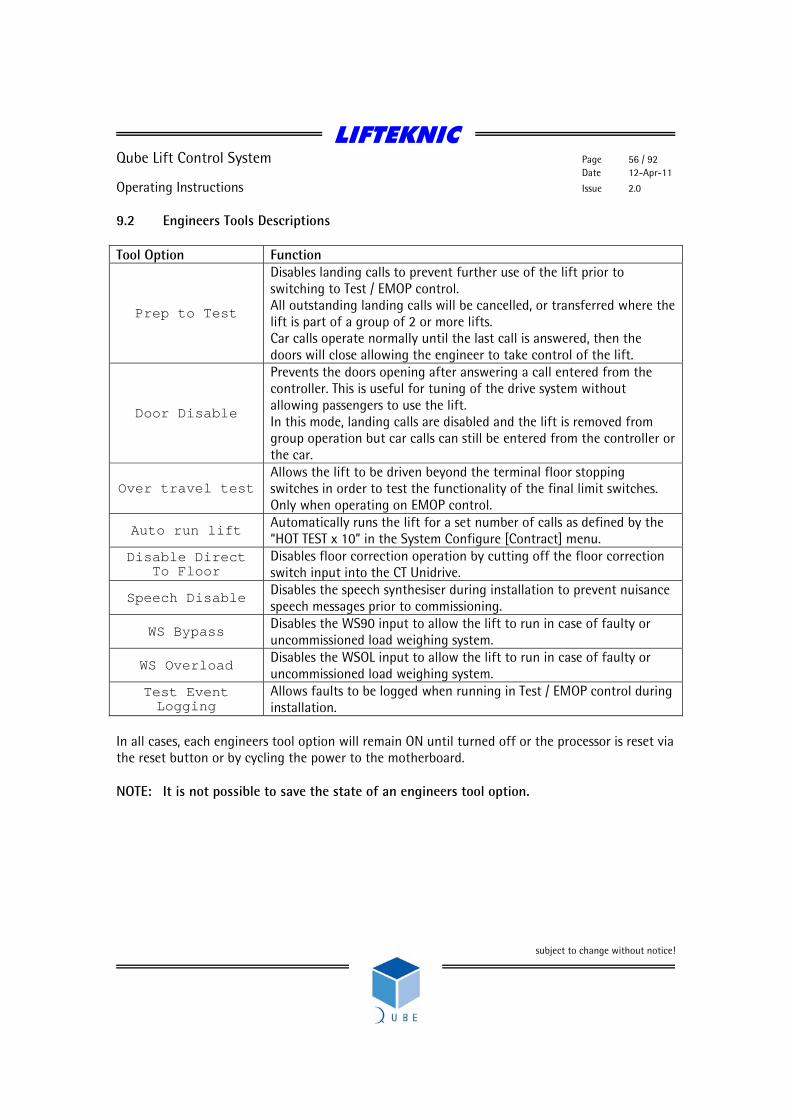
LIFTEKNIC
Qube Lift Control System Page 56 / 92 Date 12-Apr-11
Operating Instructions Issue 2.0
subject to change without notice!
9.2 Engineers Tools Descriptions Tool Option Function
Prep to Test
Disables landing calls to prevent further use of the lift prior to switching to Test / EMOP control. All outstanding landing calls will be cancelled, or transferred where the lift is part of a group of 2 or more lifts. Car calls operate normally until the last call is answered, then the doors will close allowing the engineer to take control of the lift.
Door Disable
Prevents the doors opening after answering a call entered from the controller. This is useful for tuning of the drive system without allowing passengers to use the lift. In this mode, landing calls are disabled and the lift is removed from group operation but car calls can still be entered from the controller or the car.
Over travel test Allows the lift to be driven beyond the terminal floor stopping switches in order to test the functionality of the final limit switches. Only when operating on EMOP control.
Auto run lift Automatically runs the lift for a set number of calls as defined by the “HOT TEST x 10” in the System Configure [Contract] menu.
Disable Direct To Floor
Disables floor correction operation by cutting off the floor correction switch input into the CT Unidrive.
Speech Disable Disables the speech synthesiser during installation to prevent nuisance speech messages prior to commissioning.
WS Bypass Disables the WS90 input to allow the lift to run in case of faulty or uncommissioned load weighing system.
WS Overload Disables the WSOL input to allow the lift to run in case of faulty or uncommissioned load weighing system.
Test Event Logging
Allows faults to be logged when running in Test / EMOP control during installation.
In all cases, each engineers tool option will remain ON until turned off or the processor is reset via the reset button or by cycling the power to the motherboard. NOTE: It is not possible to save the state of an engineers tool option.

LIFTEKNIC
Qube Lift Control System Page 57 / 92 Date 12-Apr-11
Operating Instructions Issue 2.0
subject to change without notice!
10 System I/O Descriptions 10.1 Standard Input Designations on QMB
Spare Inputs 1-4 are commonly used for:- SI1- Brake switch SI2- Terminal floor limit trip SI3- Fire alarm SI4- Fire switch Shaft Signals 1-4 are commonly used for:- SS1- Speed 1 slow up (Tapehead) SS2- Speed 1 slow down (Tapehead) SS3- Position reset(PSE)/Top floor reset(Tapehead) SS4- Terminal floor switch(PSE)/Bottom floor reset(Tapehead)
Inputs Key Description Plug Terminal 1 MS Safety Circuit Feed JP6 3 2 NORM Normal control JP6 4 3 TEST Car-top test control JP6 5 4 EMOP Emergency operation JP6 6 5 EUP Emergency up push JP6 7 6 EDN Emergency down push JP6 8 7 GL1 Car gate contact JP6 9 8 GL2 Landing gate contacts JP6 10 9 SI1 Spare Input 1 JP8 1 10 SI2 Spare Input 2 JP8 2 11 SI3 Spare Input 3 JP8 3 12 SI4 Spare Input 4 JP8 4 13 PFRR Phase failure/thermistor trip JP8 5 14 K2 Main contactor energised JP8 6 15 K4 Contactor release check JP8 7 16 Drive ok JP8 8 17 SS1 Shaft Signal 1 JP4 1 18 SS2 Shaft Signal 2 JP4 2 19 SS3 Shaft Signal 3 JP4 3 20 SS4 Shaft Signal 4 JP4 4 21 DST Down stopping signal JP4 5 22 UST Up stopping signal JP4 6 23 DZEN ADO enable JP4 7 24 DZ Door Zone JP4 8
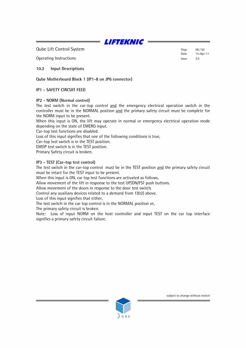
LIFTEKNIC
Qube Lift Control System Page 58 / 92 Date 12-Apr-11
Operating Instructions Issue 2.0
subject to change without notice!
10.2 Input Descriptions Qube Motherboard Block 1 (IP1-8 on JP6 connector) IP1 - SAFETY CIRCUIT FEED IP2 - NORM (Normal control) The test switch in the car-top control and the emergency electrical operation switch in the controller must be in the NORMAL position and the primary safety circuit must be complete for the NORM input to be present. When this input is ON, the lift may operate in normal or emergency electrical operation mode depending on the state of EMERG input. Car-top test functions are disabled. Loss of this input signifies that one of the following conditions is true, Car-top test switch is in the TEST position. EMOP test switch is in the TEST position. Primary Safety circuit is broken. IP3 - TEST (Car-top test control) The test switch in the car-top control must be in the TEST position and the primary safety circuit must be intact for the TEST input to be present. When this input is ON, car top test functions are activated as follows, Allow movement of the lift in response to the test UP/DN/FST push buttons. Allow movement of the doors in response to the door test switch. Control any auxiliary devices related to a demand from 1)&2) above. Loss of this input signifies that either, The test switch in the car top control is in the NORMAL position or, The primary safety circuit is broken. Note: Loss of input NORM on the host controller and input TEST on the car top interface signifies a primary safety circuit failure.

LIFTEKNIC
Qube Lift Control System Page 59 / 92 Date 12-Apr-11
Operating Instructions Issue 2.0
subject to change without notice!
IP4 - EMOP (Emergency Electrical Operation) The test switch in the car-top control must be in the NORMAL position and the emergency electrical operation switch in the controller must be in the TEST position and the primary safety circuit must be complete for the EMERG input to be present. When this input is ON it is possible to drive the lift using the up/down push-buttons on the controller providing the gate-lock inputs 1&2 are both ON. Emergency electrical operation is also known as panel test and in this mode it is possible to drive the lift without the car top I/O unit being present. Loss of this input signifies that one of the following conditions is true, Car-top test switch is in the TEST position. Emergency electrical operation switch is in the NORMAL position Primary Safety circuit is broken. IP5 - EMOP UP (Emergency Operation Up Push) When the control system is in emergency electrical operation mode and the emergency operation up push button is pressed, EMOP_UP input is active and power is fed to the gate lock circuit. The control will then energise the necessary outputs to allow the lift to move in the up direction at test speed providing the gate lock circuit is made. IP6 - EMOP DN (Emergency Operation Down Push) When the control system is in emergency electrical operation mode and the emergency operation up push button is pressed, EMOP_DN input is active and power is fed to the gate lock circuit. The control will then energise the necessary outputs to allow the lift to move in the down direction at test speed providing the gate lock circuit is made. IP7 - GATE LOCK 1 (Car gate contact) Monitors the state of the car gate contact, this signal must be present before a normal run is allowed. Loss of this signal during travel will cause an emergency stop of the lift. The gate lock function check ensures that this signal is lost when the doors have opened fully. If the signal is still present with the doors fully open, then the lift will be prevented from further operation. IP8 - GATE LOCK 2 (Landing Gate Contacts) Monitors the state of the landing gate contacts. Operation as GL1 above. Note: The gate lock circuit may be by-passed during pre-opening of the doors. If the doors reach the fully open position before the stopping sequence has completed the DOL signal will be lost before the gate lock signals (causing the gate lock function check to fail). In this case the software must perform an Emergency stop, ensuring that all movement controls are released immediately. The gate lock function check may then be re-validated.

LIFTEKNIC
Qube Lift Control System Page 60 / 92 Date 12-Apr-11
Operating Instructions Issue 2.0
subject to change without notice!
Qube Motherboard Block 2 (IP9-16 on JP8 connector) IP9/10/11/12 – SPARE INPUTS (110VAC) These inputs can be designated as required to suit a specific controller application. The functions shown below can be utilised as required and are set in the controller software prior to delivery.
• FINAL LIMIT FEED (Qube VF Hydraulic only) Monitors the supply to the Top Final Limit
• TOP FINAL LIMIT (Qube VF Hydraulic only)
Monitors the top final limit. If the FINAL LIMIT FEED input is on and the TOP FINAL LIMIT input is lost then the microprocessor will register the fault and shutdown. If the lift sinks down re-making the input, the system will remain in the shutdown state. The power to the lift controller must be switched off/on to reset this condition.
• BRAKE LIFTED SWITCH • BRAKE WEAR SWITCH • TERMINAL LIMIT MONITOR • FIRE ALARM • FIREMANS SWITCH • MAIN FLOOR FIRE SENSOR • BATTERY SUPPLY CONNECTED • AUTOMATIC RESCUE SELECTED • RESCUE DIRECTION
IP13 - PFRR (EMERGENCY/HYDRAULIC RECALL) Checks the status of the mains supply monitor (PFRR). If a fault is detected, by loss of the input, any travel in the up direction will be aborted and the lift will return to the designated recall (lowest for hydraulic) level and shut down after opening and closing the doors to allow any passengers to vacate the lift car. IP14 - MAIN CONTACTOR (Lift Running) Monitors the lift running contactors indicate that the lift is moving. Failure of this signal to operate, within an adjustable time of a start command, will result in a start failure fault being recorded in the event logger. The lift doors will cycle before a further attempt to start is made. Loss of this signal during travel will cause an emergency stop. A variable, accessible from the keypad will allow the customer to set the number of restarts before the lift is shutdown.

LIFTEKNIC
Qube Lift Control System Page 61 / 92 Date 12-Apr-11
Operating Instructions Issue 2.0
subject to change without notice!
IP15 - CONTACTOR RELEASE CHECK This input monitors all the relays, contactors and other devices that should release after each journey. The input should be present before initialisation, but will be lost immediately after initialisation of each journey. If the input remains in the off state after the lift has stopped, further use of the lift will be prohibited and a fault will be recorded in the event logger. IP16 - DRIVE OK This input monitors the Fault/Alarm contact from the motor-drive system. This contact should be in the closed position if the drive is on-line and opens if a drive fault occurs. If this contact is open then microprocessor should try to reset the drive using the DRES output if a demand is present. If a drive fault occurs during a travel of the lift then the an Emergency stop will occur.
LIFTEKNIC
Qube Lift Control System Page 62 / 92 Date 12-Apr-11
Operating Instructions Issue 2.0
subject to change without notice!
Qube Motherboard Block 3 (IP17-24 on JP4 connector) IP17/18/19/20 – SPARE INPUTS (24VDC) These inputs can be designated as required to suit a specific controller application. The functions shown below can be utilised as required and are set in the controller software prior to delivery.
• MID-SHAFT RESET • TERMINAL FLOOR SWITCH • SU1/SD1 (Up/Down Slowing Signal @ HS1)
Monitors the SU1/SD1 stepping signal in the shaft when running on high speed 1. The internal position counter of the processor is incremented or decremented, depending on the direction of the lift, on the leading edge of the signal, if a call is present at the next floor the lift will slow down on the trailing edge of the signal. If the lift slows or is already slowing from a higher speed this signal will cancel the call and allow operation of any announciator devices at the landing or in the lift car.
• TFR (TOP FLOOR RESET)
Monitors the state of the top floor reset switch. When the input is on, the reset switch is made and the microprocessor will synchronise its internal position counter to the top floor set in the system. The lift uses the position of the top floor reset limit as its slowdown point during an upwards terminal floor dive operation to allow a controlled stop at the top floor level.
• BFR (BOTTOM FLOOR RESET)
Monitors the state of the bottom floor reset switch. When the input is on, the reset switch is made and the microprocessor will synchronise its internal position counter to the bottom floor set in the system. The lift uses the position of the bottom floor reset limit as its slowdown point during a downwards terminal floor dive operation to allow a controlled stop at the bottom floor level. Note: The reset limit signals are also used as direction checking devices, please refer to description later in this manual.
• RE-LEVEL STOP (Re-levelling stop signal) (Qube VF-Hydraulic only, usually on IP20)
This input is only monitored during a re-levelling operation. When the lift strays away from the floor level, but remains inside the door zone the input should be in the on position. The input will switch off to give the stop signal after a re-levelling operation has been performed

LIFTEKNIC
Qube Lift Control System Page 63 / 92 Date 12-Apr-11
Operating Instructions Issue 2.0
subject to change without notice!
IP21 - DOWN STOP (Down Stopping Signal) This input signals the microprocessor to begin the stopping sequence in the down direction, after slowing at the appropriate point in the shaft. The floor levelling accuracy in the down direction is set using this input in conjunction with the levelling speed of the drive system. DST is also used in conjunction with input DZ for door zone verification. IP22 - UP STOP (Up Stopping Signal) This input signals the microprocessor to begin the stopping sequence in the up direction, after slowing at the appropriate point in the shaft. The floor levelling accuracy in the up direction is set using this input in conjunction with the levelling speed of the drive system. UST is also used in conjunction with input DZ for door zone verification. IP23 - RE-LEVELLING ENABLE (Advance Door Open/Re-levelling Enable) When this input is present it means that the safety circuit by-pass module (HSP-01-E) is satisfied that the door zone switching sequence has been successfully achieved during the previous operation of the lift. Unless this input is present, the gate lock by-pass contact (A21/A25) will not operate. This means that any operation that allows movement of the lift with open doors, such as advance door opening or re-levelling, will be disabled. IP24 - DZ (DOOR ZONE) When this input is present, in conjunction with UST or DST, the control board can begin the door open sequence prior to the lift stopping at the target floor providing that the safety circuit by-pass module has verified the door zone switching sequence. This signal must also be present, in conjunction with UST or DST, in order for re-levelling operation to occur. Note: The signals DST/UST/DZ must be proven to have released during the each travel of the lift. An error in operation of one of these signals means that and any operation that allows movement of the lift with open doors, such as advance door opening or re-levelling, will be disabled.
LIFTEKNIC
Qube Lift Control System Page 64 / 92 Date 12-Apr-11
Operating Instructions Issue 2.0
subject to change without notice!
Qube RIO/LIO – I/O board 1 IP1 - DOOR OPEN LIMIT Monitors the state of the door open limit. This input should be off when the doors are in the fully open position and on at all other times. If this signal remains off with the doors fully closed and the gate lock signals present or the doors are fully open and the gate lock signals are still present the gate lock function check ensures that the lift is prevented from further operation. IP2 - DOOR CLOSE LIMIT Monitors the state of the door close limit. This input should be off when the doors are in the fully closed position and on at all other times. The lift will be prevented from starting if this signal is not lost when the doors have closed. Once the lift has started the signal may be switched on again, as is the case when a stall condition is applied to the door operator during lift travel. IP3 - DOOR OPEN PUSH This input is operated by the door open push situated within the lift car. When the door open push is pressed the doors will always attempt to open as long as the lift is stopped and is within a valid door zone. IP4 - DOOR CLOSE PUSH This input is operated by the door close push situated within the lift car. When the door close push is pressed the doors will always attempt to close immediately as long as the door open push is not operated or the doors are not being obstructed. IP5 - SAFETY EDGE/LIGHT SCREEN This input is operated by the safety detector situated on the car door edge. When an obstruction is detected by the safety edge the doors will attempt to re-open if they are closing. This input is only active as long as the lift is stopped within a valid door zone. IP6 - GOODS/SPECIAL SERVICE Operated by keyswitch in the lift car. When this input is activated all landing calls are cancelled and the car will park at a floor level with open doors and only respond to car calls. The doors can only be closed by pressing and holding a car call push until the doors have fully closed and the lift has started. When the first car call in the direction of travel has been answered the doors will open automatically and cancel all remaining calls. FIRE SERVICE (Fire Recall Switch ) This signal is activated by operation of the fire recall switch mounted at the main entrance floor of the building, adjacent to the lift entrance. When activated the lift will return to the fire recall level.
LIFTEKNIC
Qube Lift Control System Page 65 / 92 Date 12-Apr-11
Operating Instructions Issue 2.0
subject to change without notice!
IP7 - WS90 (By-Pass load switch) Detects the fully loaded condition of lift. When this input is set the car will remain at a landing with the doors parked in the open position until a car call is entered. Once moving the lift will by-pass all landing calls, stopping only for the next car call in the direction of travel. When the lift is at the main floor and operating on up peak mode the doors will automatically close once this input is activated. IP8 - WSOL (Car overload switch) Detects the overloaded (110% of contract load) condition of the lift. When this input is set the car will remain at a landing with the doors parked in the open position until the load is reduced. During this time an indicator in the lift car will be illuminated, a buzzer will sound and if a speech synthesiser is fitted to the lift, an announcement advising a reduction of the lift load will be made.
LIFTEKNIC
Qube Lift Control System Page 66 / 92 Date 12-Apr-11
Operating Instructions Issue 2.0
subject to change without notice!
Qube RIO/LIO – I/O board 2 IP1 - TEST UP (Car-top Test Up Push) When the control system is in car top test mode and the test up push button is pressed, TUP input is active and power is fed to the gate lock circuit. The control will then energise the necessary outputs to allow the lift to move in the up direction at test speed providing the gate lock circuit is made. IP2 - TEST DOWN (Car-top Test Down Push) When the control system is in car top test mode and the test down push button is pressed, TDN input is active and power is fed to the gate lock circuit. The control will then energise the necessary outputs to allow the lift to move in the down direction at test speed providing the gate lock circuit is made. IP3 - DOOR TEST OPEN (Car-top Door Open Test Switch) When activated, gives the DOOR OPEN output to command the doors to open. Only operates when in Car-top test mode. IP4 - DOOR TEST CLOSE (Car-top Door Close Test Switch) When activated, gives the DOOR CLOSE output to command the doors to close. Only operates when in Car-top test mode. IP5/6/7/8 – FI1/2/3/4 (SPARE INPUTS - 24VDC) These inputs can be designated as required to suit a specific controller application. The functions shown below can be utilised as required and are set in the controller software prior to delivery.
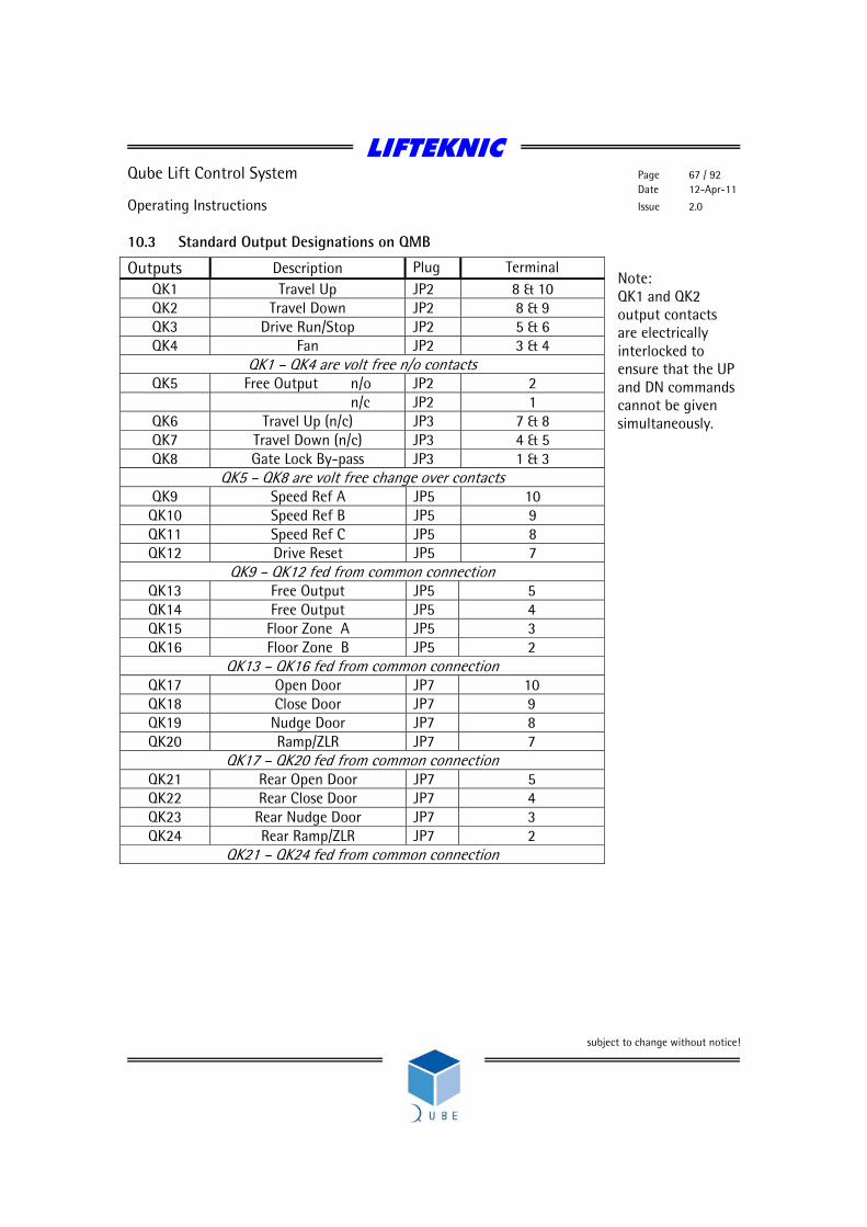
LIFTEKNIC
Qube Lift Control System Page 67 / 92 Date 12-Apr-11
Operating Instructions Issue 2.0
subject to change without notice!
10.3 Standard Output Designations on QMB Note: QK1 and QK2 output contacts are electrically interlocked to ensure that the UP and DN commands cannot be given simultaneously.
Outputs Description Plug Terminal QK1 Travel Up JP2 8 & 10 QK2 Travel Down JP2 8 & 9 QK3 Drive Run/Stop JP2 5 & 6 QK4 Fan JP2 3 & 4
QK1 – QK4 are volt free n/o contacts QK5 Free Output n/o JP2 2
n/c JP2 1 QK6 Travel Up (n/c) JP3 7 & 8 QK7 Travel Down (n/c) JP3 4 & 5 QK8 Gate Lock By-pass JP3 1 & 3
QK5 – QK8 are volt free change over contacts QK9 Speed Ref A JP5 10 QK10 Speed Ref B JP5 9 QK11 Speed Ref C JP5 8 QK12 Drive Reset JP5 7
QK9 – QK12 fed from common connection QK13 Free Output JP5 5 QK14 Free Output JP5 4 QK15 Floor Zone A JP5 3 QK16 Floor Zone B JP5 2
QK13 – QK16 fed from common connection QK17 Open Door JP7 10 QK18 Close Door JP7 9 QK19 Nudge Door JP7 8 QK20 Ramp/ZLR JP7 7
QK17 – QK20 fed from common connection QK21 Rear Open Door JP7 5 QK22 Rear Close Door JP7 4 QK23 Rear Nudge Door JP7 3 QK24 Rear Ramp/ZLR JP7 2
QK21 – QK24 fed from common connection
LIFTEKNIC
Qube Lift Control System Page 68 / 92 Date 12-Apr-11
Operating Instructions Issue 2.0
subject to change without notice!
10.4 Output Descriptions QK1 & QK6 - TRAVEL UP (Up Demand) Initiates an UP travel in response to a call above the lift. The gate lock inputs must be present and all safety checks completed before the up demand relay is energised. UR must stay on for a short time after the speed outputs are released to allow the stopping action to be controlled by the Unidrive inverter. QK2 & QK7 - TRAVEL DOWN (Down Demand) Initiates a DOWN travel in response to a call below the lift. The gate lock inputs must be present and all safety checks completed before the down demand relay is energised. DR must stay on for a short time after the speed outputs are released to allow the stopping action to be controlled by the Unidrive inverter. QK3 - RUN This output relay, in conjunction with the safety logic panel, initiates the drive system when movement of the lift is required. Once the lift reaches its destination, this relay will release and controls the release of the main contactors after the stopping sequence has been completed. QK4 – FAN (Cabinet ventillation fan) This output energises each time the lift runs and remains energised for 5 minutes after the last journey has completed. QK8 - GATE LOCK BY-PASS This output is energised only when the lift is in automatic mode and allowed to move with the doors open, such as during advance door opening or re-levelling. If any error is detected in the operation of the door zone switches or safety circuit by-pass module, the output will be disabled. QK5/13/14 – Free outputs These outputs can be designated as required to suit a specific controller application. The functions shown below can be utilised as required and are set in the controller software prior to delivery.
• Floor Correction Switch Enable • SMU threshold • Alarm Filter • Landing Network Disconnect
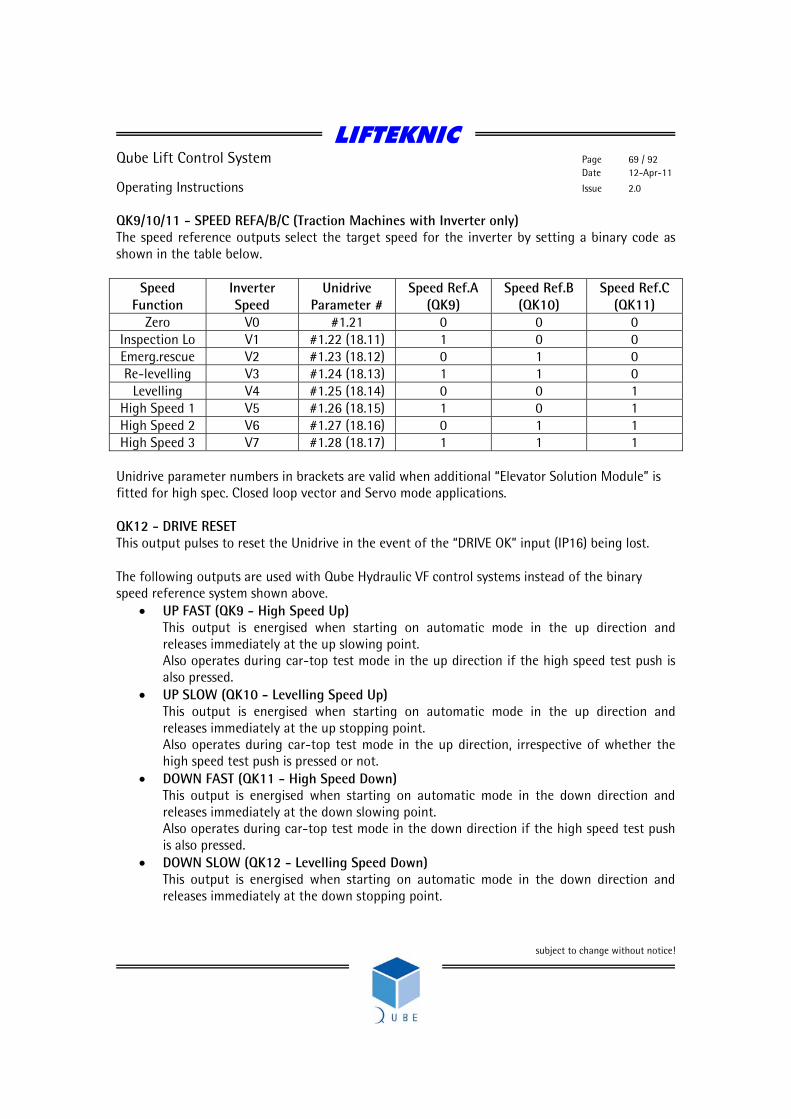
LIFTEKNIC
Qube Lift Control System Page 69 / 92 Date 12-Apr-11
Operating Instructions Issue 2.0
subject to change without notice!
QK9/10/11 - SPEED REFA/B/C (Traction Machines with Inverter only) The speed reference outputs select the target speed for the inverter by setting a binary code as shown in the table below.
Speed Function
Inverter Speed
Unidrive Parameter #
Speed Ref.A (QK9)
Speed Ref.B (QK10)
Speed Ref.C (QK11)
Zero V0 #1.21 0 0 0 Inspection Lo V1 #1.22 (18.11) 1 0 0 Emerg.rescue V2 #1.23 (18.12) 0 1 0 Re-levelling V3 #1.24 (18.13) 1 1 0
Levelling V4 #1.25 (18.14) 0 0 1 High Speed 1 V5 #1.26 (18.15) 1 0 1 High Speed 2 V6 #1.27 (18.16) 0 1 1 High Speed 3 V7 #1.28 (18.17) 1 1 1
Unidrive parameter numbers in brackets are valid when additional “Elevator Solution Module” is fitted for high spec. Closed loop vector and Servo mode applications. QK12 - DRIVE RESET This output pulses to reset the Unidrive in the event of the “DRIVE OK” input (IP16) being lost. The following outputs are used with Qube Hydraulic VF control systems instead of the binary speed reference system shown above.
• UP FAST (QK9 - High Speed Up) This output is energised when starting on automatic mode in the up direction and releases immediately at the up slowing point. Also operates during car-top test mode in the up direction if the high speed test push is also pressed.
• UP SLOW (QK10 - Levelling Speed Up) This output is energised when starting on automatic mode in the up direction and releases immediately at the up stopping point. Also operates during car-top test mode in the up direction, irrespective of whether the high speed test push is pressed or not.
• DOWN FAST (QK11 - High Speed Down) This output is energised when starting on automatic mode in the down direction and releases immediately at the down slowing point. Also operates during car-top test mode in the down direction if the high speed test push is also pressed.
• DOWN SLOW (QK12 - Levelling Speed Down) This output is energised when starting on automatic mode in the down direction and releases immediately at the down stopping point.

LIFTEKNIC
Qube Lift Control System Page 70 / 92 Date 12-Apr-11
Operating Instructions Issue 2.0
subject to change without notice!
Also operates during car-top test mode in the down direction, irrespective of whether the high speed test push is pressed or not.
• INSP (Inspection Speed) This output is energised all the time that the controller is on car-top test mode or emergency electrical operation mode. The lift speed is selected by this input in conjunction with the relevant speed input as described above.
QK15 - Floor Zone A QK16 - Floor Zone B QK17 - OPEN DOOR (Door Open Control) Provides the door open signal to the door operator, either directly to a door regulator or via a contactor. In automatic mode DOC will energise to open the lift doors providing the door open limit is not broken and the lift is stopping or stopped within a valid door zone. In car top test mode DOC will energise to open the lift doors when the door test open switch is operated, irrespective of the state of the door open limit. QK18 - CLOSE DOOR (Door Close Control) Provides the door close signal to the door operator, either directly to a door regulator or via a contactor. In automatic mode DCC will energise to close the lift doors providing the door close limit is not broken and all other safety conditions are met. In car top test mode DCC will energise to close the lift doors when the door test close switch is operated, irrespective of the state of the door close limit. QK19 – NUDGE DOOR (Door Nudging Control) Provides the door nudging signal to the door operator, either directly to a door regulator or via a contactor. Required to forcibly close the doors, at a reduced torque and speed, under emergency conditions or when the lift is held up for an unreasonable time period by the user. When nudging is active the safety edge input is ignored but the door open push input remains active. QK20 - RAMP (Ramp Contactor Control) Controls the retiring ramp solenoid when used with Express/Bennie AC doors or manual gates. QK21/2/3/4 – Repeat of QK17/18/19/20 but used for rear door control
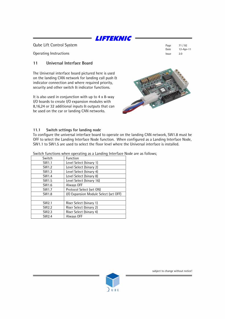
LIFTEKNIC
Qube Lift Control System Page 71 / 92 Date 12-Apr-11
Operating Instructions Issue 2.0
subject to change without notice!
11 Universal Interface Board The Universal interface board pictured here is used on the landing CAN network for landing call push & indicator connection and where required priority, security and other switch & indicator functions. It is also used in conjunction with up to 4 x 8-way I/O boards to create I/O expansion modules with 8,16,24 or 32 additional inputs & outputs that can be used on the car or landing CAN networks. 11.1 Switch settings for landing node To configure the universal interface board to operate on the landing CAN network, SW1.8 must be OFF to select the Landing Interface Node function. When configured as a Landing Interface Node, SW1.1 to SW1.5 are used to select the floor level where the Universal interface is installed. Switch functions when operating as a Landing Interface Node are as follows;
Switch Function SW1.1 Level Select (binary 1) SW1.2 Level Select (binary 2) SW1.3 Level Select (binary 4) SW1.4 Level Select (binary 8) SW1.5 Level Select (binary 16) SW1.6 Always OFF SW1.7 Protocol Select (set ON) SW1.8 I/O Expansion Module Select (set OFF)
SW2.1 Riser Select (binary 1) SW2.2 Riser Select (binary 2) SW2.3 Riser Select (binary 4) SW2.4 Always OFF
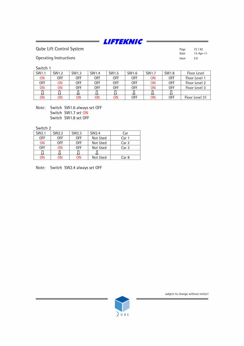
LIFTEKNIC
Qube Lift Control System Page 72 / 92 Date 12-Apr-11
Operating Instructions Issue 2.0
subject to change without notice!
Switch 1 SW1.1 SW1.2 SW1.3 SW1.4 SW1.5 SW1.6 SW1.7 SW1.8 Floor Level
ON OFF OFF OFF OFF OFF ON OFF Floor Level 1 OFF ON OFF OFF OFF OFF ON OFF Floor Level 2 ON ON OFF OFF OFF OFF ON OFF Floor Level 3
ON ON ON ON ON OFF ON OFF Floor Level 31
Note: Switch SW1.6 always set OFF
Switch SW1.7 set ON Switch SW1.8 set OFF
Switch 2 SW2.1 SW2.2 SW2.3 SW2.4 Car
OFF OFF OFF Not Used Car 1 ON OFF OFF Not Used Car 2 OFF ON OFF Not Used Car 3
ON ON ON Not Used Car 8
Note: Switch SW2.4 always set OFF
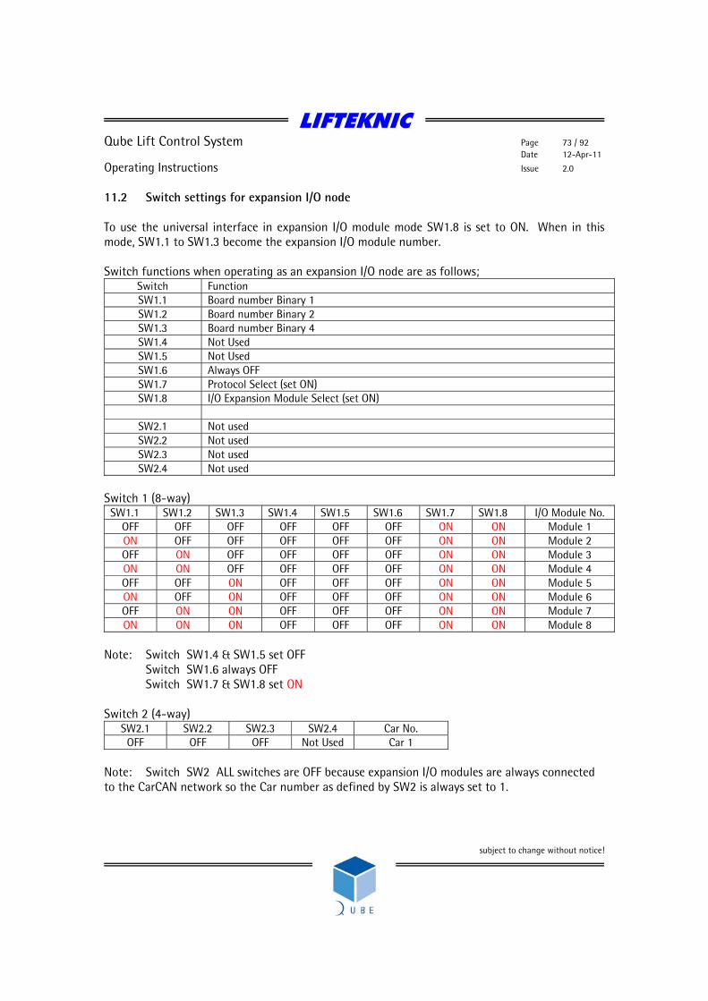
LIFTEKNIC
Qube Lift Control System Page 73 / 92 Date 12-Apr-11
Operating Instructions Issue 2.0
subject to change without notice!
11.2 Switch settings for expansion I/O node To use the universal interface in expansion I/O module mode SW1.8 is set to ON. When in this mode, SW1.1 to SW1.3 become the expansion I/O module number. Switch functions when operating as an expansion I/O node are as follows;
Switch Function SW1.1 Board number Binary 1 SW1.2 Board number Binary 2 SW1.3 Board number Binary 4 SW1.4 Not Used SW1.5 Not Used SW1.6 Always OFF SW1.7 Protocol Select (set ON) SW1.8 I/O Expansion Module Select (set ON)
SW2.1 Not used SW2.2 Not used SW2.3 Not used SW2.4 Not used
Switch 1 (8-way)
SW1.1 SW1.2 SW1.3 SW1.4 SW1.5 SW1.6 SW1.7 SW1.8 I/O Module No. OFF OFF OFF OFF OFF OFF ON ON Module 1 ON OFF OFF OFF OFF OFF ON ON Module 2 OFF ON OFF OFF OFF OFF ON ON Module 3 ON ON OFF OFF OFF OFF ON ON Module 4 OFF OFF ON OFF OFF OFF ON ON Module 5 ON OFF ON OFF OFF OFF ON ON Module 6 OFF ON ON OFF OFF OFF ON ON Module 7 ON ON ON OFF OFF OFF ON ON Module 8
Note: Switch SW1.4 & SW1.5 set OFF
Switch SW1.6 always OFF Switch SW1.7 & SW1.8 set ON
Switch 2 (4-way)
SW2.1 SW2.2 SW2.3 SW2.4 Car No. OFF OFF OFF Not Used Car 1
Note: Switch SW2 ALL switches are OFF because expansion I/O modules are always connected to the CarCAN network so the Car number as defined by SW2 is always set to 1.

LIFTEKNIC
Qube Lift Control System Page 74 / 92 Date 12-Apr-11
Operating Instructions Issue 2.0
subject to change without notice!
11.3 Binary Reference Table (Floor 1 to floor 32)
Level SW1.1 SW1.2 SW1.3 SW1.4 SW1.5 SW1.6 XX OFF OFF OFF OFF OFF OFF 1 ON OFF OFF OFF OFF OFF 2 OFF ON OFF OFF OFF OFF 3 ON ON OFF OFF OFF OFF 4 OFF OFF ON OFF OFF OFF 5 ON OFF ON OFF OFF OFF 6 OFF ON ON OFF OFF OFF 7 ON ON ON OFF OFF OFF 8 OFF OFF OFF ON OFF OFF 9 ON OFF OFF ON OFF OFF 10 OFF ON OFF ON OFF OFF 11 ON ON OFF ON OFF OFF 12 OFF OFF ON ON OFF OFF 13 ON OFF ON ON OFF OFF 14 OFF ON ON ON OFF OFF 15 ON ON ON ON OFF OFF 16 OFF OFF OFF OFF ON OFF 17 ON OFF OFF OFF ON OFF 18 OFF ON OFF OFF ON OFF 19 ON ON OFF OFF ON OFF 20 OFF OFF ON OFF ON OFF 21 ON OFF ON OFF ON OFF 22 OFF ON ON OFF ON OFF 23 ON ON ON OFF ON OFF 24 OFF OFF OFF ON ON OFF 25 ON OFF OFF ON ON OFF 26 OFF ON OFF ON ON OFF 27 ON ON OFF ON ON OFF 28 OFF OFF ON ON ON OFF 29 ON OFF ON ON ON OFF 30 OFF ON ON ON ON OFF 31 ON ON ON ON ON OFF 32 OFF OFF OFF OFF OFF ON
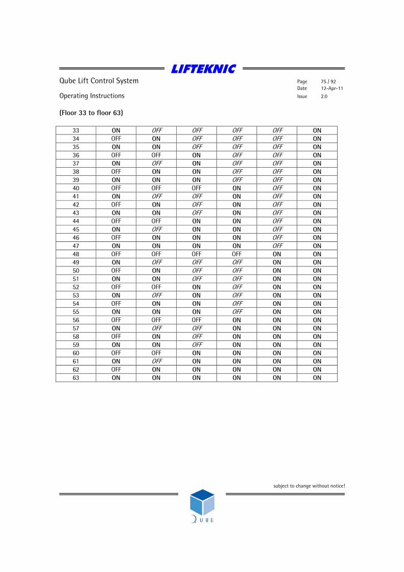
LIFTEKNIC
Qube Lift Control System Page 75 / 92 Date 12-Apr-11
Operating Instructions Issue 2.0
subject to change without notice!
(Floor 33 to floor 63)
33 ON OFF OFF OFF OFF ON 34 OFF ON OFF OFF OFF ON 35 ON ON OFF OFF OFF ON 36 OFF OFF ON OFF OFF ON 37 ON OFF ON OFF OFF ON 38 OFF ON ON OFF OFF ON 39 ON ON ON OFF OFF ON 40 OFF OFF OFF ON OFF ON 41 ON OFF OFF ON OFF ON 42 OFF ON OFF ON OFF ON 43 ON ON OFF ON OFF ON 44 OFF OFF ON ON OFF ON 45 ON OFF ON ON OFF ON 46 OFF ON ON ON OFF ON 47 ON ON ON ON OFF ON 48 OFF OFF OFF OFF ON ON 49 ON OFF OFF OFF ON ON 50 OFF ON OFF OFF ON ON 51 ON ON OFF OFF ON ON 52 OFF OFF ON OFF ON ON 53 ON OFF ON OFF ON ON 54 OFF ON ON OFF ON ON 55 ON ON ON OFF ON ON 56 OFF OFF OFF ON ON ON 57 ON OFF OFF ON ON ON 58 OFF ON OFF ON ON ON 59 ON ON OFF ON ON ON 60 OFF OFF ON ON ON ON 61 ON OFF ON ON ON ON 62 OFF ON ON ON ON ON 63 ON ON ON ON ON ON

LIFTEKNIC
Qube Lift Control System Page 76 / 92 Date 12-Apr-11
Operating Instructions Issue 2.0
subject to change without notice!
12 Mounting the Panels The Qube control panel can be installed in a floor standing or wall mounted configuration to best suit the available machine room space. 12.1 Floor Standing In the floor standing configuration, the Micro panel is fixed to the top of the Power panel using 4 x 10mm bolts. A 200mm plinth is supplied which should be fixed to the bottom of the Power panel. It is recommended that the plinth is utilised as it raises the control panel to an acceptable height to allow easy access to the drive system keypad. A cabinet ventilation fan and exhaust are fitted to the door of the power panel to ensure that the drive system operates within its environmental limits. The doors on both panels are hinged on the right hand side as standard but can be changed to the left hand side on site if necessary. 12.2 Wall mounted Where wall mounting is necessary, the panels should be mounted side by side with the Micro panel to the LHS of the Power panel. A 2m inter-connection cable extension is supplied as standard but this can be made longer on request where it is not possible to mount the Micro & Power panels together.

LIFTEKNIC
Qube Lift Control System Page 77 / 92 Date 12-Apr-11
Operating Instructions Issue 2.0
subject to change without notice!
13 Quick start routine for Qube Micro with UnidriveSP drive The sequence below should be followed to enable initial movement of the lift before the lift car is wired or to allow a rotating self-tune of the lift motor before the ropes are fitted.
• Connect mains supply and hoist motor, including brake and encoder wiring (if fitted). Ensure that any EMC guidance shown on wiring diagrams is adhered to.
• Ensure that the selector switch on the EMOP pendant (shown right) is in
the INSPECTION position, then switch on the main supply to the controller and fit the battery link at top of terminal rail in the Qube Micro panel. The LCD displays on the Qube MotherBoard (QMB) and the UnidriveSP should illuminate as shown below
QMB display UnidriveSP display
• Now switch off the main supply at the isolator and fit any temporary links required to
enable the lift to move on EMOP control. Temporary links are required for the primary safety circuit as follows; MS – MS0 MS0 – MS1 Emergency stop push MS1 – MS2 Pit stop push/slack rope switch MS2 – MS3 Final limits & buffer switch MS3 – MS4 Overspeed governor switch MS4 – MS7 Safety gear switch & car-top control Fitting all of the links shown above allows for progressive removal of links as safety circuit devices are connected to the controller. However, for expediency linking MS – MS7 is also possible.
Pos: 1 Dir: <> Status: Handwind Doors : Undef Stopped M/s 0.0
03.02 0.0 RPM
Speed feedback

LIFTEKNIC
Qube Lift Control System Page 78 / 92 Date 12-Apr-11
Operating Instructions Issue 2.0
subject to change without notice!
Temporary links are required for the secondary safety circuit as follows; MS9 – GS Car-top control/gate lock feed GS – GS1 Car gate contact GS1 – GS2 Landing gate contacts TLF – TLC Up terminal limt TLC – TLE Down terminal limit Again, fitting all of the links shown above allows for progressive removal of links as safety circuit devices are connected to the controller. In this case, the minimum linking requirement is MS9 – GS1 – GS2 – TLC. This is to ensure that the necessary gate lock inputs are present to allow the lift to move under EMOP control.
• Switch on the mains supply at the isolator, the Qube Micro should now display as follows
QMB display
Note: If ”Status:Handwind” or ”Status:Safety-CCT”, then some
temporary links are still required. If ”Status:Shutdown”, then there is an input conflict on the Qube Micro, probably due to incorrect fitting of the temporary links.
• When ”Status:EMOP” is displayed, press and hold E on the MMI, the screen should now show some basic system settings as follows;
QMB display
At this point, check that the parameter “SSys” is set to 1 or 2. This will allow movement of the lift/motor on EMOP control prior to the Position System Encoder (PSE) being fitted. If “SSys” is set to 3 or 4, refer to section 4 “Controller Configuration” on how to change this setting. Note: If the PSE system is being used, remember to change “SSys” back to 3 before learning the lift shaft once the PSE has been connected.
Pos: 1 Dir: <> Status: EMOP Doors : Open Stopped M/s 0.0
Lift: 1 Simplex Bot : 1 Top : 4 Park: 1 Fire: 1 Nets: 2 SSys: 3

LIFTEKNIC
Qube Lift Control System Page 79 / 92 Date 12-Apr-11
Operating Instructions Issue 2.0
subject to change without notice!
• Where a drive unit is fitted it should be checked that the correct motor and encoder data is programmed into the parameters (see chapter 11). Once this data is entered correctly, an auto-tune should be carried out to ensure that the drive has the correct motor model data (refer to the drive manual for procedure). A static auto-tune must be performed and if possible (i.e. ropes are removed from machine), then a rotating auto-tune should be performed to give the best possible drive performance. Now the lift is ready to run under EMOP control. If the lift moves in the wrong direction it will be necessary to swap over two of the phases between the motor and the controller. If the lift travels in the correct direction but is slow and draws a high current, it will indicate a problem with the encoder wiring, if wiring connections seem correct try reversing the encoder signals.
• To move the lift from the car-top it will be necessary to fit and wire the car-top control
unit. This will require the trailing cable to be installed and all the relevent trailing flexes to be connected back to the controller. Where the RIO interface is to be used, only the power supply and the screened/twisted pair for the CAN network need be connected back to the controller as all the CTC signals connect directly to the I/O in the RIO. However, it is strongly recommended that any available safety devices are also connected at this stage (e.g. emergnecy stop, safety gear switch, car gate contact etc..). The system also requires the DOL input to be on (indicating doors closed) before running on inspection control, link DOL-COV to achieve this prior to the door limits being connected.
• Before attempting to run the lift on high-speed ensure that all safety-circuit components
are connected and that any short-circuit connections that had been fitted to enable the installation to proceed, should now be removed. Where the PSE (Position Encoder) is fitted, follow the set-up instructions in the PSE manual.
LIFTEKNIC
Qube Lift Control System Page 80 / 92 Date 12-Apr-11
Operating Instructions Issue 2.0
subject to change without notice!
14 Unidrive SP – Standard Lift Drive 14.1 Introduction The Qube control system utilises a basic Unidrive SP inverter for geared AC machine applications which allows open loop operation for lift speeds up to 1.0m/s or closed loop operation for lift speeds up to 1.6m/s. An enhanced Unidrive SP inverter is utilised for all gearless AC machines and high speed geared AC machines whereby lift specific software, loaded into an application module, is fitted. This software provides the necessary features required effective high speed/high quality operation. In these cases, please refer to the “UnidriveSP Elevator Solution” user guide for set-up guidance. The Unidrive SP configured in its basic form includes the features shown below;
• Simple parameter assignment with the aid of a smart card - no keyboard or PC necessary • Fully automatic, self-adjusting optimisation (auto-tune) • 7 separate speeds using 3 inputs in a binary configuration • Separately adjustable acceleration and deceleration • Separately adjustable S-shaped transition (jerk rates) for starting and running • Load transfer and stopping controller can be separately optimised • Integrated brake control system with adjustable stopping profile settings • Temperature-controlled ventilation fan speed • Dynamically adjustable switching frequency for long IGBT lifetime • Wide range of encoder feedback devices supported
The inverter is set-up using the following basic parameters and then adjusted to suit specific site requirements by implementing the set-up procedure that follows. 14.2 Assigning parameters To set-up the UnidriveSP inverter to operate with the Qube control system, the following parameters must be changed from the factory default settings to the settings shown in the ‘O.Lp’ column for open loop operation or the ‘C.Lp’ column for closed loop operation. This is done by entering the data via the Unidrive SP keypad, programming via CTSoft using a PC or by loading from a pre-programmed smart card (see X.X – Smart Card Programming). If entering the data via the keypad, first ensure that #0.48 Security Status = L2. Note: These settings do not apply if the UnidriveSP is fitted with the application module containing the enhanced lift software.
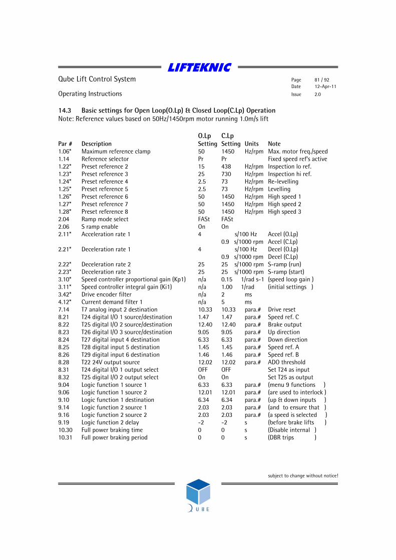
LIFTEKNIC
Qube Lift Control System Page 81 / 92 Date 12-Apr-11
Operating Instructions Issue 2.0
subject to change without notice!
14.3 Basic settings for Open Loop(O.Lp) & Closed Loop(C.Lp) Operation Note: Reference values based on 50Hz/1450rpm motor running 1.0m/s lift O.Lp C.Lp Par # Description Setting Setting Units Note 1.06* Maximum reference clamp 50 1450 Hz/rpm Max. motor freq./speed 1.14 Reference selector Pr Pr Fixed speed ref’s active 1.22* Preset reference 2 15 438 Hz/rpm Inspection lo ref. 1.23* Preset reference 3 25 730 Hz/rpm Inspection hi ref. 1.24* Preset reference 4 2.5 73 Hz/rpm Re-levelling 1.25* Preset reference 5 2.5 73 Hz/rpm Levelling 1.26* Preset reference 6 50 1450 Hz/rpm High speed 1 1.27* Preset reference 7 50 1450 Hz/rpm High speed 2 1.28* Preset reference 8 50 1450 Hz/rpm High speed 3 2.04 Ramp mode select FASt FASt 2.06 S ramp enable On On 2.11* Acceleration rate 1 4 s/100 Hz Accel (O.Lp) 0.9 s/1000 rpm Accel (C.Lp) 2.21* Deceleration rate 1 4 s/100 Hz Decel (O.Lp) 0.9 s/1000 rpm Decel (C.Lp) 2.22* Deceleration rate 2 25 25 s/1000 rpm S-ramp (run) 2.23* Deceleration rate 3 25 25 s/1000 rpm S-ramp (start) 3.10* Speed controller proportional gain (Kp1) n/a 0.15 1/rad s-1 (speed loop gain ) 3.11* Speed controller integral gain (Ki1) n/a 1.00 1/rad (initial settings ) 3.42* Drive encoder filter n/a 2 ms 4.12* Current demand filter 1 n/a 5 ms 7.14 T7 analog input 2 destination 10.33 10.33 para.# Drive reset 8.21 T24 digital I/O 1 source/destination 1.47 1.47 para.# Speed ref. C 8.22 T25 digital I/O 2 source/destination 12.40 12.40 para.# Brake output 8.23 T26 digital I/O 3 source/destination 9.05 9.05 para.# Up direction 8.24 T27 digital input 4 destination 6.33 6.33 para.# Down direction 8.25 T28 digital input 5 destination 1.45 1.45 para.# Speed ref. A 8.26 T29 digital input 6 destination 1.46 1.46 para.# Speed ref. B 8.28 T22 24V output source 12.02 12.02 para.# ADO threshold 8.31 T24 digital I/O 1 output select OFF OFF Set T24 as input 8.32 T25 digital I/O 2 output select On On Set T25 as output 9.04 Logic function 1 source 1 6.33 6.33 para.# (menu 9 functions ) 9.06 Logic function 1 source 2 12.01 12.01 para.# (are used to interlock ) 9.10 Logic function 1 destination 6.34 6.34 para.# (up & down inputs ) 9.14 Logic function 2 source 1 2.03 2.03 para.# (and to ensure that ) 9.16 Logic function 2 source 2 2.03 2.03 para.# (a speed is selected ) 9.19 Logic function 2 delay -2 -2 s (before brake lifts ) 10.30 Full power braking time 0 0 s (Disable internal ) 10.31 Full power braking period 0 0 s (DBR trips )
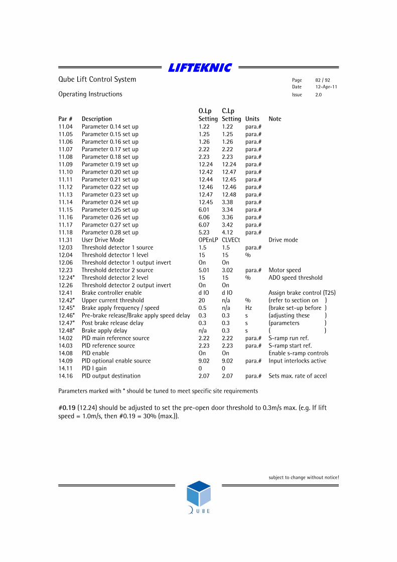
LIFTEKNIC
Qube Lift Control System Page 82 / 92 Date 12-Apr-11
Operating Instructions Issue 2.0
subject to change without notice!
O.Lp C.Lp Par # Description Setting Setting Units Note 11.04 Parameter 0.14 set up 1.22 1.22 para.# 11.05 Parameter 0.15 set up 1.25 1.25 para.# 11.06 Parameter 0.16 set up 1.26 1.26 para.# 11.07 Parameter 0.17 set up 2.22 2.22 para.# 11.08 Parameter 0.18 set up 2.23 2.23 para.# 11.09 Parameter 0.19 set up 12.24 12.24 para.# 11.10 Parameter 0.20 set up 12.42 12.47 para.# 11.11 Parameter 0.21 set up 12.44 12.45 para.# 11.12 Parameter 0.22 set up 12.46 12.46 para.# 11.13 Parameter 0.23 set up 12.47 12.48 para.# 11.14 Parameter 0.24 set up 12.45 3.38 para.# 11.15 Parameter 0.25 set up 6.01 3.34 para.# 11.16 Parameter 0.26 set up 6.06 3.36 para.# 11.17 Parameter 0.27 set up 6.07 3.42 para.# 11.18 Parameter 0.28 set up 5.23 4.12 para.# 11.31 User Drive Mode OPEnLP CLVECt Drive mode 12.03 Threshold detector 1 source 1.5 1.5 para.# 12.04 Threshold detector 1 level 15 15 % 12.06 Threshold detector 1 output invert On On 12.23 Threshold detector 2 source 5.01 3.02 para.# Motor speed 12.24* Threshold detector 2 level 15 15 % ADO speed threshold 12.26 Threshold detector 2 output invert On On 12.41 Brake controller enable d IO d IO Assign brake control (T25) 12.42* Upper current threshold 20 n/a % (refer to section on ) 12.45* Brake apply frequency / speed 0.5 n/a Hz (brake set-up before ) 12.46* Pre-brake release/Brake apply speed delay 0.3 0.3 s (adjusting these ) 12.47* Post brake release delay 0.3 0.3 s (parameters ) 12.48* Brake apply delay n/a 0.3 s ( ) 14.02 PID main reference source 2.22 2.22 para.# S-ramp run ref. 14.03 PID reference source 2.23 2.23 para.# S-ramp start ref. 14.08 PID enable On On Enable s-ramp controls 14.09 PID optional enable source 9.02 9.02 para.# Input interlocks active 14.11 PID I gain 0 0 14.16 PID output destination 2.07 2.07 para.# Sets max. rate of accel Parameters marked with * should be tuned to meet specific site requirements #0.19 (12.24) should be adjusted to set the pre-open door threshold to 0.3m/s max. (e.g. If lift speed = 1.0m/s, then #0.19 = 30% (max.)).

LIFTEKNIC
Qube Lift Control System Page 83 / 92 Date 12-Apr-11
Operating Instructions Issue 2.0
subject to change without notice!
14.4 Smart card programming The control unit is delivered ready-programmed by the manufacturer but can be easily set up by using a smart card in the case where the drive mode needs to be changed or if the drive must be replaced. To check whether programming has been carried out, look at parameter #0.29. In a programmed controller this has the value 1 but is otherwise 0. The original data set was programmed on SP2403(11kW) inverter. When programming other drive sizes, the message "C.rtg" may be displayed and if an option module is fitted inside the drive, the message "C.Optn" may be displayed. These messages must be acknowledged by pressing the RED Reset button on the keypad. The smart card will normally contain the inverter settings when the controller is delivered, stored as data set 1. 14.5 Saving and restoring complete parameter sets to and from the Smartcard To store a complete parameter set on a Smartcard
Set #xx.00 to a value of 3yyy e.g. Your closed loop lift setup could be 3002 (i.e. data set 2) Your open loop lift setup could be 3003 (i.e. data set 3) etc...
If a data set already exists in a location that you wish to update, first delete the existing settings by
Set #xx.00 to a value of 7yyy e.g. To delete your closed loop lift setup would be 7002 To delete your open loop lift setup would be 7003 etc...
The new data set can then be stored as above To view what each file is on the smartcard Go to #11.37 - This will scoll through the parameter sets on the card. If it does not scroll you only have 1 parameter file. Once you have selected which smartcard file you are looking at go to #11.38 - This tells you which control mode the smartcard parameters are saved for. To read a complete parameter set back into the drive
Set #xx.00 to a value of 6yyy e.g. Your closed loop lift parameters would be restored from 6002
Your open loop lift parameters would be restored from 6003 etc... For a detailed description on SMARTCARD Operation see section 9 of the Unidrive SP User Guide.

LIFTEKNIC
Qube Lift Control System Page 84 / 92 Date 12-Apr-11
Operating Instructions Issue 2.0
subject to change without notice!
14.6 System start-up on site Start-up can be carried out on site in just a few steps as follows
• Enter Motor Nameplate Details • Set Contract Parameters • Auto-tuning • Optimising starting • Optimising the travel curve • Optimising the motor slip • Optimising stopping • Optimising the brake controller
14.6.1 Enter Motor Nameplate Details The following values must be set based on the motor data plate values
• #0.42 Number of poles (set to “Auto” for drive to auto-calculate) • #0.43 Motor power factor / cos phi (auto-calculated with rotating auto-tune) • #0.44 Rated motor voltage (check if motor is Star or Delta connected) • #0.45 Rated motor speed (rpm) • #0.46 Rated motor current (A) • #0.47 Rated motor frequency (Hz)
14.6.2 Set Contract Parameters The following values must be set based on the lift contract speed/rated motor speed, all references should be in “Hz” for O.Lp operation or “rpm” for C.Lp operation.
• #0.02 = Maximum reference clamp (Hz/rpm) • #0.03 = (100 / #1.28) * (V_norm / aACCEL) ;(s/100Hz or s/1000rpm) • #0.04 = (100 / #1.28) * (V_norm / aDECEL) ;(s/100Hz or s/1000rpm) • #1.22 = (V_insp.lo / V_norm) * #1.28 ;For inspection speed of 0.3m/s and lift
speed 1.0m/s with 50Hz motor, then (0.3m/s / 1.0m/s) * 50Hz = 15Hz • #1.23 = (V_insp.hi / V_norm) * #1.28 ;where V_insp.hi = 0.5m/s • #1.24 = (V_lev / V_norm) * #1.28 ;For levelling speed of 0.05m/s and lift
speed 1.0m/s with 50Hz motor, then (0.05m/s / 1.0m/s) * 50Hz = 2.5Hz • #1.25 = (V_relev / V_norm) * #1.28 ;where V_relev = 0.05m/s • #1.26 = (V_hs1 / V_norm) * #1.28 ;where V_hs1 = 1.0m/s max. • #1.27 = (V_hs2 / V_norm) * #1.28 ;where V_hs2 = 1.0m/s max. • #1.28 = Motor frequency/speed for V_norm ;assuming contract speed is achieved at
rated motor speed ). Where; V_norm = Rated speed in m/s
aACCEL = Acceleration (m/s2) aDECEL = Deceleration (m/s2)
LIFTEKNIC
Qube Lift Control System Page 85 / 92 Date 12-Apr-11
Operating Instructions Issue 2.0
subject to change without notice!
14.6.3 Auto-tuning Auto-tuning is essential for good performance of the lift motor. Therefore, if auto-tuning has not previously been performed, change parameter #0.40 = 1 (static) or 2 (rotating) and then press the UP or DN button on the EMOP control pendent and hold until parameter #0.40 = 0, the auto-tune is now complete. If the auto-tune terminates early, an error code will appear on the inverter screen. Check the meaning of the code in the UnidriveSP user guide and rectify the problem before attempting to perform the auto-tune again. Please note: It is advisable that the rotating autotune is carried out for optimum performance, especially for open loop operation. However, before a rotating autotune is performed, it is necessary to remove all load from the motor (i.e. support the lift and remove the ropes from the sheave). 14.6.4 Setting the current limits The current limit parameters may be changed automatically by the autotune process so it is advisable to check the following settings before proceeding further. Motoring current limit #4.05 Regen current limit #4.06 Symmetrical current limit #4.07 The motoring current limit applies in either direction of rotation when the machine is producing motoring torque and similarly the regen current limit applies in either direction when the machine is producing regenerating torque. The symmetrical current limit can override either motoring or regenerating current limit if it is set at a lower value than either limit. Therefore, it is necessary to change all of the above parameters to the same value when setting the current limits. 14.6.5 Optimising the travel curve Optimise starting by means of a separately adjustable starting S ramp. This is set up via #0.18 and additional to the standard S-ramp jerk rate set in #0.17. Increase the setting if the lift starts with a jerk and decrease it if the lift is sluggish during initial acceleration. The default acceleration and deceleration rates are set to 0.5m/s2 for open loop operation or 0.75m/s2 for closed loop operation. Adjust acceleration #0.03 until you obtain the most comfortable start and adjust deceleration #0.04 to optimise the slowdown profile (i.e. ensure that a constant levelling speed is achieved before the stop signal is given, but also ensure that the levelling time does not exceed 2-3secs). Reduce #0.03/#0.04 for harder accel/decel or increase #0.03/#0.04 for softer accel/decel.

LIFTEKNIC
Qube Lift Control System Page 86 / 92 Date 12-Apr-11
Operating Instructions Issue 2.0
subject to change without notice!
14.6.6 Adjusting the speed controller (Closed loop only) Start the lift using EMOP or car-top test and perform the following steps to adjust the speed controller; • Adjusting the speed controller P gain Increase #0.07 in steps of 0.01 until noisy or
unstable • On hearing controller noise (increments) Increase current filter #0.27 in steps of 1ms up
to 5ms max., then increase #0.07 in further steps of 0.01 until unstable.
• On obtaining instability Reduce #0.07 to 60% of the unstable value • Adjusting the speed controller I gain Increase #0.08 from 1.0 to max. 5.0 14.6.7 Optimising the motor slip (Open loop only) The motor rated rpm (motor slip value) #0.45 must be set correctly to allow the correct relationship between the magnetising and torque producing currents. If the magnetising current is too low then the motor will be under excited and if it is too high the torque producing current will be limited, both cases resulting in poor motor control. A simple method of checking that the slip value is correct is to run the lift at levelling speed with empty car. If the motor rated speed is set correctly the motor speed in both directions should be the same due to the correct level of slip compensation being applied. If the motor speed is slower when the lift is travelling in the down direction, then #0.45 should be increased in small increments until the speeds are roughly equal. If the motor speed is slower when the lift is travelling in the up direction, then #0.45 should be decreased in small increments until the speeds are roughly equal.

LIFTEKNIC
Qube Lift Control System Page 87 / 92 Date 12-Apr-11
Operating Instructions Issue 2.0
subject to change without notice!
14.6.8 Optimising stopping (Open Loop only) The stopping mode of the motor has plays an important role in the floor levelling accuracy of the lift and can be adjusted to suit the particular characteristics of the motor being controlled. The preferred stopping mode for most lift machines is mode 1 (Ramp). However, ramping down to stop on some higher slip motors (e.g. old polechanger type motors) can result in a loss of torque under load at low frequencies. This results in poor floor levelling accuracy due to loss of control. In this case it may be necessary to change to stopping mode 4 (Timed DC injection braking stop). Using this methods will stop the motor more abruptly but will help to maintain floor levelling accuracy under different load conditions. Stopping methods options (mode O should not be used under any circumstances). Stopping Mode Phase 1 Phase 2 Comments 0: Coast Inverter disabled Drive cannot be re-
enabled for 1s Delay in phase 2 allows rotor flux to decay.
1: Ramp Ramp down to zero frequency
Wait for 1s with inverter enabled
2: Ramp followed by DC injection
Ramp down to zero frequency
Inject DC at level specified by #6.06 for time defined by #6.07
3: DC injection with zero speed detection
Low frequency current injection with detection of low speed before next phase.
Inject DC at level specified by #6.06 for time defined by #6.07
The drive automatically senses low speed and therefore it adjusts the injection time to suit the application. If the injection current level is too small the drive will not sense low speed (normally a minimum of 50-60% is required).
4: Timed DC injection braking stop
Inject DC at level specified by #6.06 for time defined by #6.07.
No phase 2.
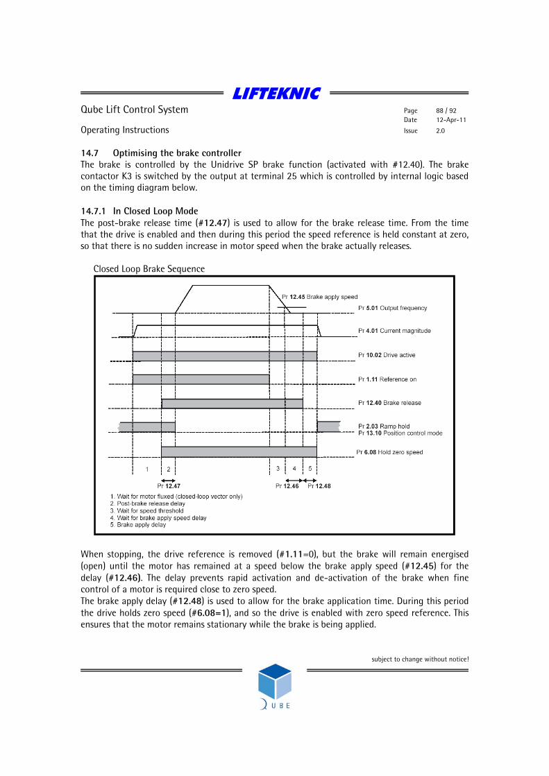
LIFTEKNIC
Qube Lift Control System Page 88 / 92 Date 12-Apr-11
Operating Instructions Issue 2.0
subject to change without notice!
14.7 Optimising the brake controller The brake is controlled by the Unidrive SP brake function (activated with #12.40). The brake contactor K3 is switched by the output at terminal 25 which is controlled by internal logic based on the timing diagram below. 14.7.1 In Closed Loop Mode The post-brake release time (#12.47) is used to allow for the brake release time. From the time that the drive is enabled and then during this period the speed reference is held constant at zero, so that there is no sudden increase in motor speed when the brake actually releases. Closed Loop Brake Sequence
When stopping, the drive reference is removed (#1.11=0), but the brake will remain energised (open) until the motor has remained at a speed below the brake apply speed (#12.45) for the delay (#12.46). The delay prevents rapid activation and de-activation of the brake when fine control of a motor is required close to zero speed. The brake apply delay (#12.48) is used to allow for the brake application time. During this period the drive holds zero speed (#6.08=1), and so the drive is enabled with zero speed reference. This ensures that the motor remains stationary while the brake is being applied.

LIFTEKNIC
Qube Lift Control System Page 89 / 92 Date 12-Apr-11
Operating Instructions Issue 2.0
subject to change without notice!
14.7.2 In Open Loop Mode The current magnitude is compared to an upper threshold (#12.42) and a lower threshold (#12.43) by a comparator with hysteresis to give torque present and drive output open detection functions respectively. The upper and lower threshold currents are given as a percentage of motor current defined by #5.07. The upper threshold should be set to the current level that indicates that there is magnetising current and sufficient torque producing current in the motor to deliver the required amount of torque when the brake is released. The output of the comparator remains active after this level has been reached unless the current subsequently falls below the lower threshold which should be set to the required level to detect the condition where the motor has been disconnected from the drive. If the lower threshold is set greater or equal to the upper threshold, the upper threshold applies with a hysteresis band of zero. If #12.42 and #12.43 are both set to zero then the output of the comparator is always one. The frequency comparator (#12.44) is used to detect when the motor frequency has reached a level where the motor can produce the required amount of torque to ensure that the motor rotates in the demanded direction when the brake is released. This parameter should be set to a level slightly above the motor slip frequency that is likely to occur under the highest expected load that is applied to the motor when the brake is released. Open loop brake sequencing

LIFTEKNIC
Qube Lift Control System Page 90 / 92 Date 12-Apr-11
Operating Instructions Issue 2.0
subject to change without notice!
The brake apply frequency threshold (#12.45) is used to ensure that the brake is applied before the motor frequency reaches zero and to prevent the motor rotating (in the reverse direction due to an overhauling load for example) during the brake apply time. If the frequency falls below this threshold, but the motor is not required to stop (i.e. reversing direction without stopping), provided the Reference on parameter (#1.11) remains at one, the brake is not applied. This prevents the brake from activating and de-activating as the motor passes through zero speed. The pre-brake release delay (#12.46) is used to allow time for the motor torque to reach the required level before the brake is released. This time should allow for the motor flux to reach a significant proportion of the rated level (2 or 3 times the rotor time constant of the motor), and the time for slip compensation to become fully active (at least 0.5s). During the Pre-brake delay period the frequency reference is held constant (#2.03 = 1). The post-brake release delay (#12.47) is used to allow for the brake release time. During this period the frequency reference is held constant (#2.03 = 1), so that there is no sudden increase in motor speed when the brake actually releases. For more detailed information on the inverter please consult the “UnidriveSP User Guide” which can be found on the Lifteknic website, or on the CD supplied in the Qube documentation pack.
LIFTEKNIC
Qube Lift Control System Page 91 / 92 Date 12-Apr-11
Operating Instructions Issue 2.0
subject to change without notice!
LIFTEKNIC
Qube Lift Control System Page 92 / 92 Date 12-Apr-11
Operating Instructions Issue 2.0
subject to change without notice!
Lifteknic Limited 11 Victoria Road • Chester • Cheshire CH2 2AX
Tel. +44(0)1244 389690 • Fax. +44(0)1244 389691 e-mail:[email protected]