Embed Size (px)
Citation preview

BRISTOL BABCOCK DPC 33XX
CUSTOM INTERFACE MODULE
- * -
QSONIC PROTOCOL
USER MANUAL
User Manual: Version 02.00.00 - September 26, 2002.
for Firmware Versions:
A) Controller Family: * Protected Mode, Ethernet-capable System Firmware Type: PES or PEX Replaces Standard Protocols Firmware Type: PCE Custom Protocol Firmware Version: QS PCE 02.00.## Custom Protocol Firmware File: QSPCE20#.BIN
B) Controller Family: Protected Mode, pre-Ethernet System Firmware Type: PLS or PLX Replaces Standard Protocols Firmware Type: PCP Custom Protocol Firmware Version: QS PCP 02.00.## Custom Protocol Firmware File: QSPCP20#.BIN
C) Controller Family: Real Mode System Firmware Type: RMS Replaces Standard Protocols Firmware Type: STP Custom Protocol Firmware Version: XQS.20# Custom Protocol Firmware File: QSU3B20#.HEX
* = an Ethernet-capable controller may or may not be populated with Ethernet

i
CONTENTS
INTRODUCTION.............................................................. 1
GENERAL NOTES ABOUT LISTS................................................. 3LEGEND FOR LISTS.......................................................... 3VALID RANGE OR VALUES..................................................... 3
STATUS SIGNALS............................................................ 4LIST OF STATUS CODES...................................................... 4ERROR ANALYSIS............................................................ 5
CUSTOM PORT CONFIGURATION................................................. 7PORTSTATUS MODULE......................................................... 7MASTER CONFIGURATION LIST................................................. 8TEST DIAGNOSTICS LIST..................................................... 16
APPENDIX A: REVISION HISTORY............................................ A - iPRELIMINARY Version QS 00.00.00 (September 4, 1997)..................... A - iPRELIMINARY Version QS 00.00.01 (September 16, 1997).................... A - iTARGET TEST Version QS 00.01.00 (October 16, 1997)...................... A - iFIELD TEST Version QS 01.01.00 (June 25, 2001)......................... A - iiVersion QS 02.00.00 (September 26, 2002)............................... A - ii
APPENDIX B: QUICK REFERENCE............................................. B - i
APPENDIX C: RECEIVED MESSAGE DIAGNOSTICS................................ C - i
APPENDIX D: RECEIVED MESSAGE VS. DATA SIGNALS........................... D - i

1
INTRODUCTION
A Bristol Babcock Network 3000 series controller can be configured, via itsCustom Ports, to be a communications Master to a Q.Sonic SPU.The controller functions as a master on a half-duplex communications link,receiving regular data messages from the Q.Sonic (there is NO provision forcommand/response messaging).Each port acts as an independent Master, and any number of ports may be usedconcurrently for communication with Q.Sonics.
In this manual, the ‘driver’ refers to the entire suite of firmware whichhandles the Q.Sonic Master communication.The user’s ACCOL program must supply the driver with sufficient informationfor this task.In return, the driver performs communication and supplies information, fromand about the attached Q.Sonic, to the ACCOL program.In addition, the driver provides information about its own execution (thestage it is at, its success or lack thereof, the cause of any error itexperiences, etc.)The Master’s driver status is indicated in the first signal in the MasterConfiguration List: the Status signal.
For the driver to communicate as a Q.Sonic Master, a port must be configuredin Custom Q.Sonic Master mode and the ACCOL program must supply appropriatesignal lists/arrays for communication.

2
The the Q.Sonic driver can support ANY of the following configurationcombinations:
NoteStand-alone SPU (RS-485)
- orSPU+ Remote Unit (RS-232C)
and
Standard Protocol (checksum modulo 256)* or
Extended Protocol (checksum XOR inverse)
and
Standard Data Message (code 35 = Q_DATA)+ or
Extended Data Message (code 36 = Q_XDATA)+ or
Universal Data Message (code 37 = U_DATA)
and
CheckSonic, FlareSonic, P.Sonic-1 Data(quantity of acoustic paths: N = 1)
+ orCheckSonic, FlareSonic, P.Sonic-2, Q.Sonic-2 Data(quantity of acoustic paths: N = 2)
+ orQ.Sonic-3 Data (quantity of acoustic paths: N = 3)
+ orQ.Sonic-5 Data (quantity of acoustic paths: N = 5)
Notes:
- =This is an electrical configuration which does not affect the driver inany way.
* = This is selected via the user ACCOL program configuration of the driver.
+ =These are auto-detected by the driver. The contents of the MasterConfiguration List required from the user ACCOL program by the driverare sufficient for the most demanding combination of codes 35/36/37 andN = 1/2/3/5 (i.e. all of the signals must always be present, but some ofthese may be ignored depending upon the actual combination in use).
Valid combinations are: 35:1,3,5 36:3,5 37:1,2,3,5
3
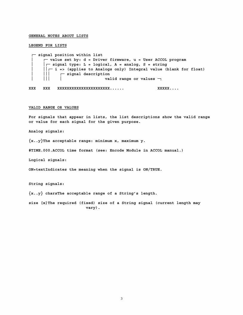
GENERAL NOTES ABOUT LISTS
LEGEND FOR LISTS
signal position within list value set by: d = Driver firmware, u = User ACCOL program signal type: L = logical, A = analog, S = string i => (applies to Analogs only) Integral value (blank for float) signal description valid range or values
XXX XXX XXXXXXXXXXXXXXXXXXXXXX...... XXXXX....
VALID RANGE OR VALUES
For signals that appear in lists, the list descriptions show the valid rangeor value for each signal for the given purpose.
Analog signals:
{x..y}The acceptable range: minimum x, maximum y.
#TIME.000.ACCOL time format (see: Encode Module in ACCOL manual.)
Logical signals:
ON=textIndicates the meaning when the signal is ON/TRUE.
String signals:
{x..y} charsThe acceptable range of a String’s length.
size [x]The required (fixed) size of a String signal (current length mayvary).

4
STATUS SIGNALS
The Master Configuration List contains, as its first signal, a Status.The value of this signal is a status code indicating the status of the driver.It may be an interim value, or indicate a fatal or non-fatal error.
Notes on Status Codes
A final status greater than zero is non-fatal: processing continued to the endand the first non-fatal error that was encountered is reported.
A final status less than zero is fatal: processing was not completed.
Signals will be updated up to the point at which a fatal error is encountered,so that partially-updated lists can result when a fatal error occurs.
Wildcards in Status Values
+/- XXXX =the signal/element number, within the ACCOL list, of the signalthat caused the error.
LIST OF STATUS CODES
8XXXX = unable to store value to signal
100 = overheard a command/response - message ignored
0 = successful completion, awaiting next data message
-1 = mode not supported by Custom Firmware (see ACCOL User Manual)
-31 = I/O request general failure -32 = received character overrun error -33 = received character parity error -34 = received character framing error -36 = received message format error -38 = receive timeout
-41 = received message checksum error -42 = received message syntax error
-1XXXX = signal/element is absent or of incorrect type
-2XXXX = invalid signal/element value
-6YYYY = validation error

5
ERROR ANALYSIS
? = apparent hang with no apparent status code settingThis occurs if some error is made in configuration such that there is no way
to indicate the error.
For example, if the Custom Port parameter P1 is set to a value which does notcorrespond to an existing list, the driver cannot indicate the problembecause it cannot place a status code value in a signal (the Statussignal is in the list which has been misidentified).
Possible errors of this sort are:the Custom Port parameter P1 (Master Configuration List Number) contains a
number for which there is no list,the Master Configuration List does not contain an Analog signal as its first
entry,the Status signal in the Master Configuration List is Control Inhibited (in
this case, driver execution DOES continue, but no statusescan ever be reported).
Once these points have been passed, errors can be reported.
8XXXX = driver could not store value to signal -indicates a problem with a signal in the current list: -the driver is to unable to update a signal (usually because it is control-
inhibited, or due to truncation of a string value) -to correct the problem, either use a different signal or modify the
troublesome signal’s attributes -note that this is not a fatal error; processing continues, and the first
such error is reported
100 = overheard a command/response - message ignored -indicates that a command or response message was overheard -the message is reported in the Last Received Message signal -the message contents are ignored
0 = successful completion, awaiting next data message -no error occurred during the most recent reception -the driver is waiting to receive another data message
-1 = mode not supported by custom EPROM -this value is placed in the Custom module STATUS terminal when the user
attempts to configure a port for Custom Q.Sonic Master mode withoutfirst installing a Custom EPROM which supports the mode; refer to theACCOL User Manual
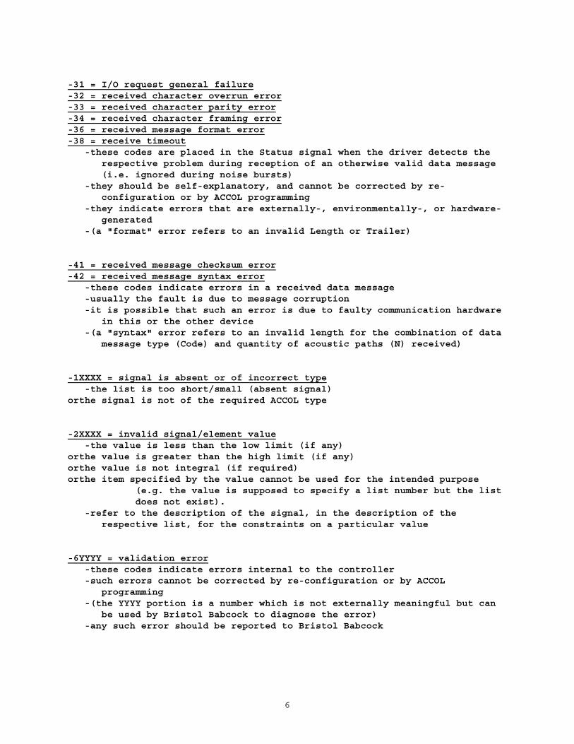
6
-31 = I/O request general failure-32 = received character overrun error-33 = received character parity error-34 = received character framing error-36 = received message format error-38 = receive timeout -these codes are placed in the Status signal when the driver detects the
respective problem during reception of an otherwise valid data message(i.e. ignored during noise bursts)
-they should be self-explanatory, and cannot be corrected by re-configuration or by ACCOL programming
-they indicate errors that are externally-, environmentally-, or hardware-generated
-(a "format" error refers to an invalid Length or Trailer)
-41 = received message checksum error-42 = received message syntax error -these codes indicate errors in a received data message -usually the fault is due to message corruption -it is possible that such an error is due to faulty communication hardware
in this or the other device -(a "syntax" error refers to an invalid length for the combination of data
message type (Code) and quantity of acoustic paths (N) received)
-1XXXX = signal is absent or of incorrect type -the list is too short/small (absent signal)orthe signal is not of the required ACCOL type
-2XXXX = invalid signal/element value -the value is less than the low limit (if any)orthe value is greater than the high limit (if any)orthe value is not integral (if required)orthe item specified by the value cannot be used for the intended purpose
(e.g. the value is supposed to specify a list number but the listdoes not exist).
-refer to the description of the signal, in the description of therespective list, for the constraints on a particular value
-6YYYY = validation error -these codes indicate errors internal to the controller -such errors cannot be corrected by re-configuration or by ACCOL
programming -(the YYYY portion is a number which is not externally meaningful but can
be used by Bristol Babcock to diagnose the error) -any such error should be reported to Bristol Babcock

7
CUSTOM PORT CONFIGURATION
The following are the parameter fields for a Custom port and their values whenconfigured for Q.Sonic Master mode:
MODE . . . . . .Set this field to 161 to indicate Custom Q.Sonic Master Mode.
BAUD . . . . . .Set this field to the desired communication rate.This can also be changed online via the PORTSTATUS module.
CHARACTER LENGTHThe number of data bits per character is fixed internally (8).
STOP BITS . . .The number of stop bits per character is fixed internally (1).
PARITY . . . . .Set this field to the desired character parity.This can also be changed online via the PORTSTATUS module.
P1 . . . . . . .Set this field to the Master Configuration List number{1..255}.
This can NOT be changed online via the PORTSTATUS module.
P2 . . . . . . .Set this field to the Test Diagnostics List number {1..255} or{0} for no extra diagnostics.
This can NOT be changed online via the PORTSTATUS module.
PORTSTATUS MODULE
The PORTSTATUS Module in an ACCOL program can be used to manipulate a Q.SonicCustom port in a limited manner: -Modes 0,4,5,6,7 are NOT supported -Mode 1 can be used to read the entire port configuration -Mode 2 can be used to write ONLY the BAUD_RATE and PARITY (if other
characteristics are specified, they are ignored) -Mode 3 can be used to reset the port characteristics to the original
configuration (actually changes only the BAUD_RATE and PARITY)

8
MASTER CONFIGURATION LIST
The Master Configuration List number is specified in the Custom portconfiguration parameter P1. The list supplies general operating parameters tothe driver for communication with a Q.Sonic.
Master Configuration List contents:
1 dAi Status see section on Status Codes 2 uAi Protocol Type {0=Standard,1=Extended} 3 uL DCD Required During Receive {ON=required,OFF=not-required} 4 dAi Reception Count {0..65535} wrap-around 5 dAi Data Message Type Code {35=Q_DATA,36=Q_XDATA,37=UDATA}
V-Status bits: 6 dL 00: reserved insignificant 7 dL 01: Current Output Load Error {ON=fault,OFF=ok} 8 dL 02: Current Output DAC Underflow {ON=fault,OFF=ok} 9 dL 03: Current Output DAC Overflow {ON=fault,OFF=ok} 10 dL 04: Frequency Generator Underflow {ON=fault,OFF=ok} 11 dL 05: Frequency Generator Overflow {ON=fault,OFF=ok} 12 dL 06: Reduced Accuracy {ON=reduced,OFF=normal} 13 dL 07: Security {ON=disabled,OFF=enabled} 14 dL 08: Communication Error {ON=fault,OFF=ok} 15 dL 09: Timeout Error {ON=fault,OFF=ok} 16 dL 10: reserved insignificant 17 dL 11: reserved insignificant 18 dL 12: reserved insignificant 19 dL 13: reserved insignificant 20 dL 14: reserved insignificant 21 dL 15: Remote Unit Error {ON=Remote,OFF=SPU}
C/R-Status bits: 22 dL 00: reserved insignificant 23 dL 01: Current Output Load Error {ON=fault,OFF=ok} 24 dL 02: Current Output DAC Underflow {ON=fault,OFF=ok} 25 dL 03: Current Output DAC Overflow {ON=fault,OFF=ok} 26 dL 04: Frequency Generator Underflow {ON=fault,OFF=ok} 27 dL 05: Frequency Generator Overflow {ON=fault,OFF=ok} 28 dL 06: Reduced Accuracy {ON=reduced,OFF=normal} 29 dL 07: Security {ON=disabled,OFF=enabled} 30 dL 08: Communication Error {ON=fault,OFF=ok} 31 dL 09: Timeout Error {ON=fault,OFF=ok} 32 dL 10: reserved insignificant 33 dL 11: reserved insignificant 34 dL 12: reserved insignificant 35 dL 13: reserved insignificant 36 dL 14: reserved insignificant 37 dL 15: Remote Unit Error {ON=Remote,OFF=SPU} :

9
: 38 dAi Quantity of Acoustic Paths (N) {1,2,3,5} 39 dAi Quantity of Samples Taken {0..65535} 40 dAi Path 1: Quantity of Valid Samples {0..65535} 41 dAi Path 2: Quantity of Valid Samples {0..65535} 42 dAi Path 3: Quantity of Valid Samples {0..65535} 43 dAi Path 4: Quantity of Valid Samples {0..65535} 44 dAi Path 5: Quantity of Valid Samples {0..65535} 45 dAi Path 1, Transducer A: AGC Level {0..65535} 46 dAi Path 1, Transducer B: AGC Level {0..65535} 47 dAi Path 2, Transducer A: AGC Level {0..65535} 48 dAi Path 2, Transducer B: AGC Level {0..65535} 49 dAi Path 3, Transducer A: AGC Level {0..65535} 50 dAi Path 3, Transducer B: AGC Level {0..65535} 51 dAi Path 4, Transducer A: AGC Level {0..65535} 52 dAi Path 4, Transducer B: AGC Level {0..65535} 53 dAi Path 5, Transducer A: AGC Level {0..65535} 54 dAi Path 5, Transducer B: AGC Level {0..65535} 55 dAi Path 1, Transducer A: AGC Limit {0..65535} 56 dAi Path 1, Transducer B: AGC Limit {0..65535} 57 dAi Path 2, Transducer A: AGC Limit {0..65535} 58 dAi Path 2, Transducer B: AGC Limit {0..65535} 59 dAi Path 3, Transducer A: AGC Limit {0..65535} 60 dAi Path 3, Transducer B: AGC Limit {0..65535} 61 dAi Path 4, Transducer A: AGC Limit {0..65535} 62 dAi Path 4, Transducer B: AGC Limit {0..65535} 63 dAi Path 5, Transducer A: AGC Limit {0..65535} 64 dAi Path 5, Transducer B: AGC Limit {0..65535} 65 dA (Corrected) Speed of Sound {±3.4e±38} m/s 66 dA (Corrected) Gas Velocity {±3.4e±38} m/s 67 dA Pressure {±3.4e±38} kPa 68 dA Temperature {±3.4e±38} K 69 dA Flow Rate - Line (Operating) {±3.4e±38} m3/h 70 dA Flow Rate - Base (Reference) {±3.4e±38} m3/h 71 dAi Stability {-32768..32767}
72 dA Path 1: Cpp (uncor. speed of sound) {±3.4e±38} m/s 73 dA Path 2: Cpp (uncor. speed of sound) {±3.4e±38} m/s 74 dA Path 3: Cpp (uncor. speed of sound) {±3.4e±38} m/s 75 dA Path 4: Cpp (uncor. speed of sound) {±3.4e±38} m/s 76 dA Path 5: Cpp (uncor. speed of sound) {±3.4e±38} m/s 77 dA Path 1: Vpp (uncor. gas velocity) {±3.4e±38} m/s 78 dA Path 2: Vpp (uncor. gas velocity) {±3.4e±38} m/s 79 dA Path 3: Vpp (uncor. gas velocity) {±3.4e±38} m/s 80 dA Path 4: Vpp (uncor. gas velocity) {±3.4e±38} m/s 81 dA Path 5: Vpp (uncor. gas velocity) {±3.4e±38} m/s
:

10
: 82 dA Meter Type {0..65535} 83 dA Sequence Number {0..4294967295} * 84 dA Forward [Error] Volume {±3.4e±38} m3
85 dA Reverse [Error] Volume {±3.4e±38} m3
86 dA Tspare (for future TwinSonic) {±3.4e±38} 87 dL 00: Path 1 Diagnostic Bit 00 reserved 88 dL 01: Path 1 Diagnostic Bit 01 reserved 89 dL 02: Path 1 Diagnostic Bit 02 reserved 90 dL 03: Path 1 Trans A AGC Level Status {ON=clipped,OFF=normal} 91 dL 04: Path 1 Diagnostic Bit 04 reserved 92 dL 05: Path 1 Diagnostic Bit 05 reserved 93 dL 06: Path 1 Diagnostic Bit 06 reserved 94 dL 07: Path 1 Trans B AGC Level Status {ON=clipped,OFF=normal} 95 dL 08: Path 1 Speed of Sound Status {ON=out-of-range,OFF= normal} 96 dL 09: Path 1 Gas Velocity Status {ON=out-of-range,OFF= normal} 97 dL 10: Path 1 Diagnostic Bit 10 reserved 98 dL 11: Path 1 Performance Status {ON=low,OFF=normal} 99 dL 12: Path 1 Diagnostic Bit 12 reserved100 dL 13: Path 1 Diagnostic Bit 13 reserved101 dL 14: Path 1 Diagnostic Bit 14 reserved102 dL 15: Path 1 Diagnostic Bit 15 reserved103 dL 00: Path 2 Diagnostic Bit 00 reserved104 dL 01: Path 2 Diagnostic Bit 01 reserved105 dL 02: Path 2 Diagnostic Bit 02 reserved106 dL 03: Path 2 Trans A AGC Level Status {ON=clipped,OFF=normal}107 dL 04: Path 2 Diagnostic Bit 04 reserved108 dL 05: Path 2 Diagnostic Bit 05 reserved109 dL 06: Path 2 Diagnostic Bit 06 reserved110 dL 07: Path 2 Trans B AGC Level Status {ON=clipped,OFF=normal}111 dL 08: Path 2 Speed of Sound Status {ON=out-of-range,OFF= normal}112 dL 09: Path 2 Gas Velocity Status {ON=out-of-range,OFF= normal}113 dL 10: Path 2 Diagnostic Bit 10 reserved114 dL 11: Path 2 Performance Status {ON=low,OFF=normal}115 dL 12: Path 2 Diagnostic Bit 12 reserved116 dL 13: Path 2 Diagnostic Bit 13 reserved117 dL 14: Path 2 Diagnostic Bit 14 reserved118 dL 15: Path 2 Diagnostic Bit 15 reserved119 dL 00: Path 3 Diagnostic Bit 00 reserved120 dL 01: Path 3 Diagnostic Bit 01 reserved121 dL 02: Path 3 Diagnostic Bit 02 reserved122 dL 03: Path 3 Trans A AGC Level Status {ON=clipped,OFF=normal}123 dL 04: Path 3 Diagnostic Bit 04 reserved124 dL 05: Path 3 Diagnostic Bit 05 reserved125 dL 06: Path 3 Diagnostic Bit 06 reserved126 dL 07: Path 3 Trans B AGC Level Status {ON=clipped,OFF=normal}127 dL 08: Path 3 Speed of Sound Status {ON=out-of-range,OFF= normal}128 dL 09: Path 3 Gas Velocity Status {ON=out-of-range,OFF= normal}129 dL 10: Path 3 Diagnostic Bit 10 reserved130 dL 11: Path 3 Performance Status {ON=low,OFF=normal} :
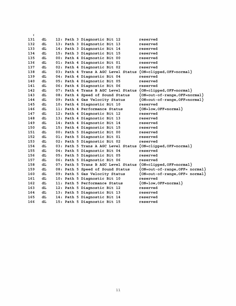
11
:131 dL 12: Path 3 Diagnostic Bit 12 reserved132 dL 13: Path 3 Diagnostic Bit 13 reserved133 dL 14: Path 3 Diagnostic Bit 14 reserved134 dL 15: Path 3 Diagnostic Bit 15 reserved135 dL 00: Path 4 Diagnostic Bit 00 reserved136 dL 01: Path 4 Diagnostic Bit 01 reserved137 dL 02: Path 4 Diagnostic Bit 02 reserved138 dL 03: Path 4 Trans A AGC Level Status {ON=clipped,OFF=normal}139 dL 04: Path 4 Diagnostic Bit 04 reserved140 dL 05: Path 4 Diagnostic Bit 05 reserved141 dL 06: Path 4 Diagnostic Bit 06 reserved142 dL 07: Path 4 Trans B AGC Level Status {ON=clipped,OFF=normal}143 dL 08: Path 4 Speed of Sound Status {ON=out-of-range,OFF=normal}144 dL 09: Path 4 Gas Velocity Status {ON=out-of-range,OFF=normal}145 dL 10: Path 4 Diagnostic Bit 10 reserved146 dL 11: Path 4 Performance Status {ON=low,OFF=normal}147 dL 12: Path 4 Diagnostic Bit 12 reserved148 dL 13: Path 4 Diagnostic Bit 13 reserved149 dL 14: Path 4 Diagnostic Bit 14 reserved150 dL 15: Path 4 Diagnostic Bit 15 reserved151 dL 00: Path 5 Diagnostic Bit 00 reserved152 dL 01: Path 5 Diagnostic Bit 01 reserved153 dL 02: Path 5 Diagnostic Bit 02 reserved154 dL 03: Path 5 Trans A AGC Level Status {ON=clipped,OFF=normal}155 dL 04: Path 5 Diagnostic Bit 04 reserved156 dL 05: Path 5 Diagnostic Bit 05 reserved157 dL 06: Path 5 Diagnostic Bit 06 reserved158 dL 07: Path 5 Trans B AGC Level Status {ON=clipped,OFF=normal}159 dL 08: Path 5 Speed of Sound Status {ON=out-of-range,OFF= normal}160 dL 09: Path 5 Gas Velocity Status {ON=out-of-range,OFF= normal}161 dL 10: Path 5 Diagnostic Bit 10 reserved162 dL 11: Path 5 Performance Status {ON=low,OFF=normal}163 dL 12: Path 5 Diagnostic Bit 12 reserved164 dL 13: Path 5 Diagnostic Bit 13 reserved165 dL 14: Path 5 Diagnostic Bit 14 reserved166 dL 15: Path 5 Diagnostic Bit 15 reserved
12
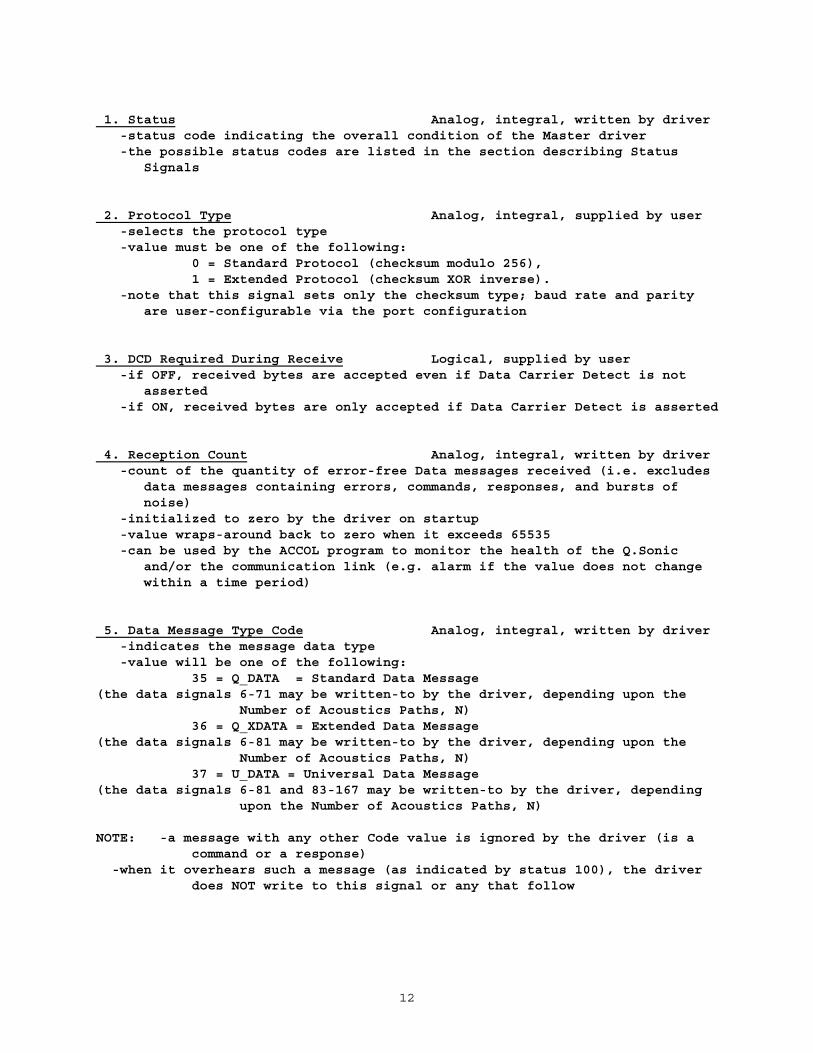
1. Status Analog, integral, written by driver -status code indicating the overall condition of the Master driver -the possible status codes are listed in the section describing Status
Signals
2. Protocol Type Analog, integral, supplied by user -selects the protocol type -value must be one of the following:
0 = Standard Protocol (checksum modulo 256),1 = Extended Protocol (checksum XOR inverse).
-note that this signal sets only the checksum type; baud rate and parityare user-configurable via the port configuration
3. DCD Required During Receive Logical, supplied by user -if OFF, received bytes are accepted even if Data Carrier Detect is not
asserted -if ON, received bytes are only accepted if Data Carrier Detect is asserted
4. Reception Count Analog, integral, written by driver -count of the quantity of error-free Data messages received (i.e. excludes
data messages containing errors, commands, responses, and bursts ofnoise)
-initialized to zero by the driver on startup -value wraps-around back to zero when it exceeds 65535 -can be used by the ACCOL program to monitor the health of the Q.Sonic
and/or the communication link (e.g. alarm if the value does not changewithin a time period)
5. Data Message Type Code Analog, integral, written by driver -indicates the message data type -value will be one of the following:
35 = Q_DATA = Standard Data Message(the data signals 6-71 may be written-to by the driver, depending upon the
Number of Acoustics Paths, N)36 = Q_XDATA = Extended Data Message
(the data signals 6-81 may be written-to by the driver, depending upon theNumber of Acoustics Paths, N)
37 = U_DATA = Universal Data Message(the data signals 6-81 and 83-167 may be written-to by the driver, depending
upon the Number of Acoustics Paths, N)
NOTE: -a message with any other Code value is ignored by the driver (is acommand or a response)
-when it overhears such a message (as indicated by status 100), the driverdoes NOT write to this signal or any that follow

13
6.-21. V-Status bits Logicals, written by driver22.-37. C/R-Status bits Logicals, written by driver -indicate individual statuses -’reserved’ bits contain meaningless values (i.e. are unused at present) -a single signal can be used for all ’reserved’ bits -layout of the two sets is identical -bits 00..14 (other than reserved bits) are ON to indicate the fault, OFF
to indicate no-fault -for bit 15, ON indicates that bits 00..14 are flagged from the Remote
unit, OFF indicates that bits 00..14 are from the SPU -no detailed explanations follow-- the names for the individual bits should
be self-explanatory and/or explained in Q.Sonic documentation
38. Quantity of Acoustic Paths (N) Analog, integral, written by driver -indicates quantity of significant data items in sets: Quantities of Valid
Samples, AGC Levels (A/B), AGC Limits (A/B), Cpp, Vpp, Diagnostic Bitsets
-value is only ever 1, 2, 3 or 5 (any other value in a received datamessage indicates a corrupted message)
-extra data items (e.g. for paths 4,5 when only 1,2,3 are reported by theQ.Sonic) must be present but will contain insignificant values
-N will only ever be 1 or 2 when a Universal Data Message (code 37 =U_DATA) is received
39. Quantity of Samples Taken Analog, integral, written by driver - indicates quantity of samples (elementary measurements) taken -range is {0..65535}
40.-44. Quantities of Valid Samples Analogs, integral, written by driver -indicates quantity of valid samples (elementary measurements) for each
individual path -extra data items (i.e. for paths 4,5 when only 1,2,3 are reported by the
Q.Sonic) must be present but will not be written-to by the driver -range is {0..65535}
45.-64. AGC Levels and Limits Analogs, integral, written by driver -indicates AGC levels and limits for each of transducers A and B for each
individual path -extra data items (i.e. for paths 4,5 when only 1,2,3 are reported by the
Q.Sonic) must be present but will not be written-to by the driver -range for each: {0..65535}
65. (Corrected) Speed of Sound Analog, written by driver -corrected, all paths’ weighted average, speed of sound -range: {±3.4e±38}, unit: metres per second

14
66. (Corrected) Gas Velocity Analog, written by driver -corrected, all paths’ weighted average, gas velocity -range: {±3.4e±38}, unit: metres per second
67. Pressure Analog, written by driver -pressure -range: {±3.4e±38}, unit: kilopascals
68. Temperature Analog, written by driver -absolute temperature -range: {±3.4e±38}, unit: kelvin
69. Flow Rate - Line (Operating) Analog, written by driver -volume flow rate at line (=operating) conditions -range: {±3.4e±38}, unit: cubic metres per hour
70. Flow Rate - Base (Reference) Analog, written by driver -volume flow rate at base (=reference) conditions -range: {±3.4e±38}, unit: cubic metres per hour
71. Stability Analog, integral, written by driver -additional status information -range: {-32768..32767}
72.-76. Cpp = (Uncorrected) Speed of Sound, Per Path Analogs, -all 5 must always be present, written by driverbut are only written-to when:Code = 36 = Q_XDATA = Extended Data Messageor Code = 37 = U_DATA = Universal Data Message(i.e. not written-to by driver when Code = 35 = Q_DATA = Standard Data
Message) -extra data items (e.g. for paths 4,5 when only 1,2,3 are reported by the
Q.Sonic) must be present but will not be written-to by the driver -range for each: {±3.4e±38 m/s}
77.-81. Vpp = (Uncorrected) Gas Velocity, Per Path Analogs, -all 5 must always be present, written by driverbut are only written-to when:Code = 36 = Q_XDATA = Extended Data Messageor Code = 37 = U_DATA = Universal Data Message(i.e. not written-to by driver when Code = 35 = Q_DATA = Standard Data
Message) -extra data items (e.g. for paths 4,5 when only 1,2,3 are reported by the
Q.Sonic) must be present but will not be written-to by the driver -range for each: {±3.4e±38 m/s}
15
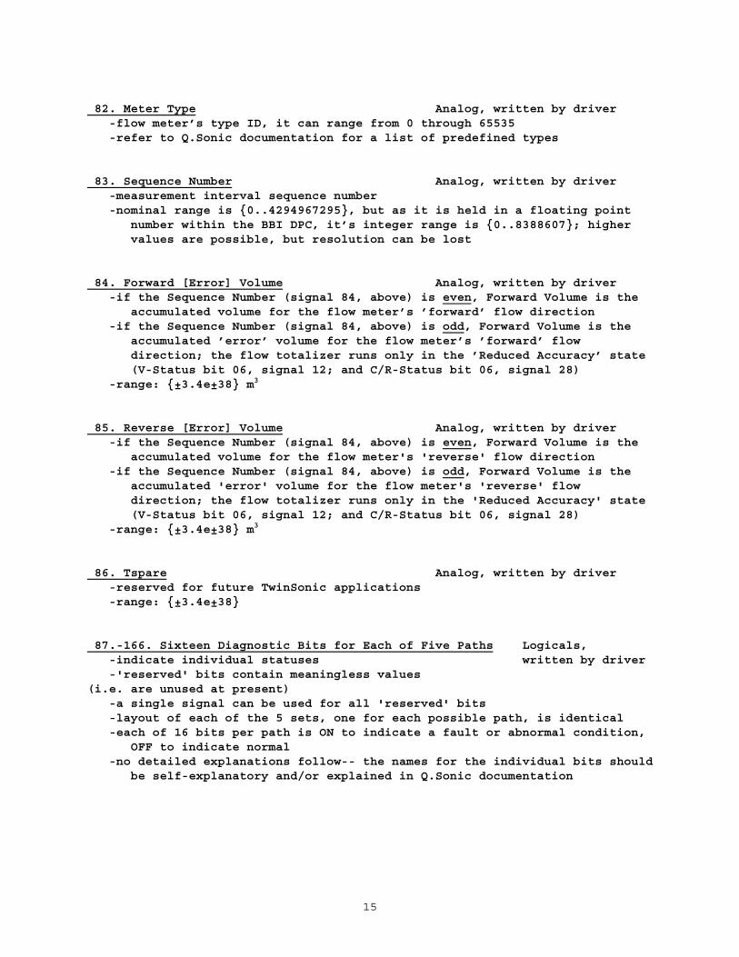
82. Meter Type Analog, written by driver -flow meter’s type ID, it can range from 0 through 65535 -refer to Q.Sonic documentation for a list of predefined types
83. Sequence Number Analog, written by driver -measurement interval sequence number -nominal range is {0..4294967295}, but as it is held in a floating point
number within the BBI DPC, it’s integer range is {0..8388607}; highervalues are possible, but resolution can be lost
84. Forward [Error] Volume Analog, written by driver -if the Sequence Number (signal 84, above) is even, Forward Volume is the
accumulated volume for the flow meter’s ’forward’ flow direction -if the Sequence Number (signal 84, above) is odd, Forward Volume is the
accumulated ’error’ volume for the flow meter’s ’forward’ flowdirection; the flow totalizer runs only in the ’Reduced Accuracy’ state(V-Status bit 06, signal 12; and C/R-Status bit 06, signal 28)
-range: {±3.4e±38} m3
85. Reverse [Error] Volume Analog, written by driver -if the Sequence Number (signal 84, above) is even, Forward Volume is the
accumulated volume for the flow meter's 'reverse' flow direction -if the Sequence Number (signal 84, above) is odd, Forward Volume is the
accumulated 'error' volume for the flow meter's 'reverse' flowdirection; the flow totalizer runs only in the 'Reduced Accuracy' state(V-Status bit 06, signal 12; and C/R-Status bit 06, signal 28)
-range: {±3.4e±38} m3
86. Tspare Analog, written by driver -reserved for future TwinSonic applications -range: {±3.4e±38}
87.-166. Sixteen Diagnostic Bits for Each of Five Paths Logicals, -indicate individual statuses written by driver -'reserved' bits contain meaningless values(i.e. are unused at present) -a single signal can be used for all 'reserved' bits -layout of each of the 5 sets, one for each possible path, is identical -each of 16 bits per path is ON to indicate a fault or abnormal condition,
OFF to indicate normal -no detailed explanations follow-- the names for the individual bits should
be self-explanatory and/or explained in Q.Sonic documentation

16
TEST DIAGNOSTICS LIST
The Test Diagnostics List number is specified in the Custom port configurationparameter P2. The list supplies diagnostic information for test purposes.
Test Diagnostics List contents:
1 dAi Status {0,-1XXXX} see Status Codes 2 dS Last Received Message size 64 -> {0..21} msg chars 3 dAi Buffer Length {0..255} 4 dAi Length in Message {0..253} 5 dS 1st Part of Received Message size 64 6 dS 2nd Part of Received Message size 64 7 dS 3rd Part of Received Message size 64 8 dS 4th Part of Received Message size 64 9 dS 5th Part of Received Message size 64 10 dS 6th Part of Received Message size 64 11 dS 7th Part of Received Message size 64 12 dS 8th Part of Received Message size 64 13 dS 9th Part of Received Message size 64 14 dS 10th Part of Received Message size 64 15 dS 11th Part of Received Message size 64 16 dS 12th Part of Received Message size 64 17 dS 13th Part of Received Message size 64 18 dS 14th Part of Received Message size 64 19 dS 15th Part of Received Message size 64 20 dS 16th Part of Received Message size 64 21 dS 17th Part of Received Message size 64 22 dS 18th Part of Received Message size 64 23 dS 19th Part of Received Message size 64 24 dS 20th Part of Received Message size 64 25 dS Checksum Result size 64 26 dS Syntax Check Result size 64 27 dS Syntax Error Result size 64

17
1. Status Analog, integral, written by driver -status code indicating the overall condition of the Test Diagnostics List -the possible status codes are confined to {0 and -1XXXX} as listed in the
section describing Status Signals -if any of the expected signals are absent or of the incorrect type, the
first such signal is indicated (all earlier signals are still updatedwith diagnostics); if all the signals are present and of the correcttype, this Status is set to 0 by the driver
2 Last Received Message String [64], written by driver -driver writes the most recently received message into the signal -message excludes preamble (xFF’s), header (x80,x81,x82,x83), trailer
(x84,x85,x86,x87) and postamble (xFF’s) -communication activity not framed by these excluded bytes is completely
ignored (i.e. treated as noise) -commands/responses that are overheard ARE displayed but are not acted upon
by the driver -each byte is shown in hexadecimal, separated by spaces -if the string is empty (current length is zero), it means that no message
was received (e.g. on startup)
3. Buffer Length Analog, integral, written by driver -indicates the quantity of bytes received by the driver after a complete,
valid Header but excluding the Trailer and optional Postamble -the value is reported even if the message is incomplete or corrupted (will
be zero if only the start of a Header was received) -note that it includes the Length and Checksum fields of the message (i.e.
in a "good" message, is 2 greater than the Length in Message)
4. Length in Message Analog, integral, written by driver -contains the value of the Length field in the message (i.e. in a "good"
message will be 2 less than the Buffer Length) -if the driver received the start of a message that was not long enough to
contain a Length, the value is zero

18
5.-24. Nth Part of Received Message String [64], written by driver -filled with received bytes from the message, between the Length and
Trailer -each byte is shown in hexadecimal, separated by spaces -format varies depending upon the Code and Qty of Paths -only the first 17 parts are used to display valid received message bytes;
the remaining three are used in displaying an invalid message’s bytes:if the Code is not 35, 36, or 37, the driver assumes that the receivedmessage is an overheard comand or response of unknown layout. Thereceived bytes are displayed 13 in each of the (at most) 20 Parts, inorder of reception (there is sufficient capacity to show an entiremaximum-length message).
Appendix C contains a map of the contents of these Nth Part signals for eachvalid COMMAND-CODE/QTY-OF-PATHS combination.
Appendix D contains tables of message bytes vs. data signals used and unusedfor each valid COMMAND-CODE/QTY-OF-PATHS combination.
25. Checksum Result String [64], written by driver -if the received message is not long enough to warrant a checksum
verification, this signal is blank -if the message is long enough, the string contains the explanation:"RCV_CS = xx , CAL_CS = yy (zzz)"where:xx is the received checksum (hex)yy is the calculated checksum (hex)zzz is the conclusion "ok" or "MISMATCH!", as appropriate

19
26. Syntax Check Result String [64], written by driver27. Syntax Error Result String [64], written by driver -these two signals operate as a pair, providing information about the
acceptability of the received message -if the receive failed at a low driver level (e.g. Configuration Status is
-3#), the Check Result string will be blank and the Error Result stringwill be one of the following:
"Driver: General Failure""Driver: Overrun Error""Driver: Parity Error""Driver: Framing Error""Driver: Format Error""Driver: Receive Timeout" -if the reception was unsuccessful at a higher level (e.g. invalid length,
invalid Qty of Paths, etc), the Check Result string will show as much ofthe Code, Qty of Paths, and Received Message Length as could bedeciphered (i.e. not all may be shown), in the form:
"Syntax Code=xx(XXX),QP=yyyy,Len=zz"wherexx = the Message Type Code in hex (usually x23/24/25 -> 35/36/37)XXX = Message Type text (usually Std/Ext/Uni -> 35/36/37)yyyy = the Quantity of Paths (N) in hexzz = Length in Message, in hexand the Error Result string with contain an explanation of why the message was
rejected, such as:"Error: Code is unknown, msg ignored""Error: QP should be YYY""Error: Len should be ZZ" -if the received message passes all syntax checks, the Check Result string
is:"Ok: Code=xx(XXX),QP=yyyy,Len=zz"and the Error Result string is blank.

A - i
APPENDIX A: REVISION HISTORY
PRELIMINARY Version QS 00.00.00 (September 4, 1997)
User manual only, for review (no associated firmware).
PRELIMINARY Version QS 00.00.01 (September 16, 1997)
User manual plus firmware for bench tests.
1.Changed title page, Table of Contents, and Revision History to reflect thisversion.
2.Protocol Type now determines only the checksum used; baud rate and paritynow set by port configuration (pp.2,7,10,Bi).
3.Added status code 100 = overheard a command/response - message ignored(pp.4,5,Bi).
4.Changed status code value -42 to -36 = received message format error(pp.4,6,Bi).
5.Deleted status codes -35, -39, -43, -44, -45 (pp.4,6,Bi).
6.Added status code -42 = received message syntax error (pp.4,6,Bi).
7.Added status codes 6YYYY = validation errors (pp.4,6,Bi).
8.Eliminated signal: Last Transmitted Message, renumbered all subsequentsignals (pp.8-12,Bii-Biii).
TARGET TEST Version QS 00.01.00 (October 16, 1997)
User manual plus firmware for target tests.
9.Changed title page, Table of Contents, and Revision History to reflect thisversion.
10.Changed user-configurability of port, added support for PORTSTATUS Module(pp.7,Bi).
11.Clarified description of driver actions when a command or response messageis overheard (p.11).
12.Clarified descriptions of occasions when driver writes to extra and sparedata items (pp.11,12).
13.Added description of Test Diagnostics List (pp.13-15,Biv).

A - ii
FIELD TEST Version QS 01.01.00 (June 25, 2001)
User manual plus firmware for field tests.
14.Changed title page, Table of Contents, and Revision History to reflect thisversion.
15.Added OPTIONAL signal to Master Configuration List: 82. DCD RequiredDuring Receive (pp.9,13,Biii).
Version QS 02.00.00 (September 26, 2002)
16.Changed title page, Table of Contents, and Revision History to reflect thisversion.
17.Removed the Last Received Message signal from the Master Configuration List(signal 3), inserted it into the Test Diagnostics List (signal 2)(pp.8,12,16).
18.Moved the DCD Required During Receive signal withinn the MasterConfiguration List, from signal 82 to signal 3 (pp.8,12,15).
THIS SIGNAL IS NOW MANDATORY.
17.Added support for Universal Data Message (code 37 = U_DATA) (pp.2,5,13).
18.Added support for CheckSonic, FlareSonic, P.Sonic-1 Data (quantity ofacoustic paths: N = 1) and CheckSonic, FlareSonic, P.Sonic-2, Q.Sonic-2Data (quantity of acoustic paths: N = 2) (pp.2,9,13).
19.Renamed the "reserved" V-Status and C/R-Status bits 06 and 07 in the MasterConfiguration List (signals 12,13,28,29) to "Reduced Accuracy" and"Security", respectively (pg.8).
20.Renamed the signals 65 and 66 of the Master Configuration List forconsistency: "Velocity of Sound" -> "(Corrected) Speed of Sound" and"Gas Velocity" -> "(Corrected) Gas Velocity" (pp.9,15).
21.Renamed the signals 72-81 of the Master Configuration List: "Spare 1" and"Spare 2" become (per path) "Cpp = (Uncorrected) Speed of Sound" and"Vpp = (Uncorrected) Gas Velocity" (pp.9,15).
22.Added signals 82 through 166 to the Master Configuration List for supportof Universal Data Message (code 37 = U_DATA) (pp.10,11,15,16).
23.Inserted new Nth Part of Received Message signals and a second Syntax ErrorResult signal to the Test Diagnostics List, in part to cover the longerUniversal Data Message (code 37 = U_DATA) (pp.16,17).
24.Added Appendix C : Received Message Diagnostics and Appendix D : ReceivedMessage vs. Data Signals.
B - i
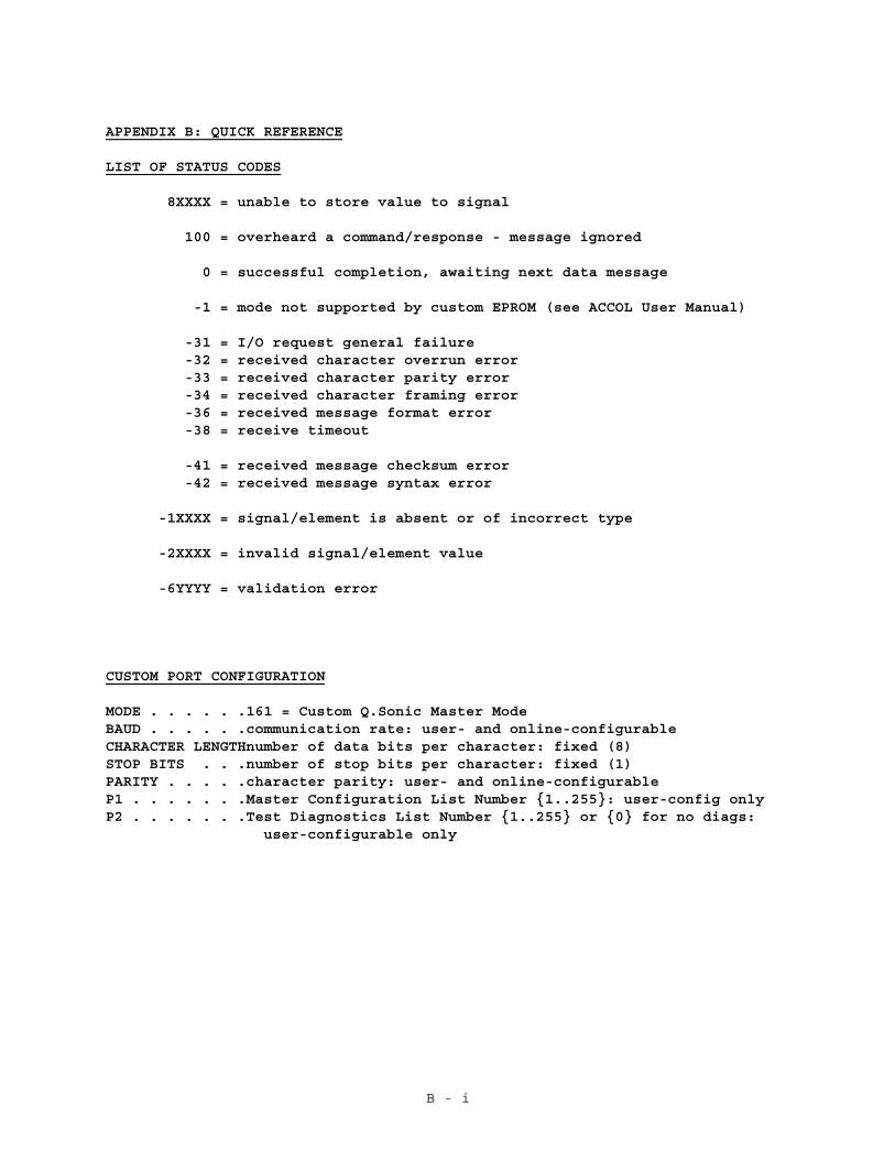
APPENDIX B: QUICK REFERENCE
LIST OF STATUS CODES
8XXXX = unable to store value to signal
100 = overheard a command/response - message ignored
0 = successful completion, awaiting next data message
-1 = mode not supported by custom EPROM (see ACCOL User Manual)
-31 = I/O request general failure -32 = received character overrun error -33 = received character parity error -34 = received character framing error -36 = received message format error -38 = receive timeout
-41 = received message checksum error -42 = received message syntax error
-1XXXX = signal/element is absent or of incorrect type
-2XXXX = invalid signal/element value
-6YYYY = validation error
CUSTOM PORT CONFIGURATION
MODE . . . . . .161 = Custom Q.Sonic Master ModeBAUD . . . . . .communication rate: user- and online-configurableCHARACTER LENGTHnumber of data bits per character: fixed (8)STOP BITS . . .number of stop bits per character: fixed (1)PARITY . . . . .character parity: user- and online-configurableP1 . . . . . . .Master Configuration List Number {1..255}: user-config onlyP2 . . . . . . .Test Diagnostics List Number {1..255} or {0} for no diags:
user-configurable only
B - ii
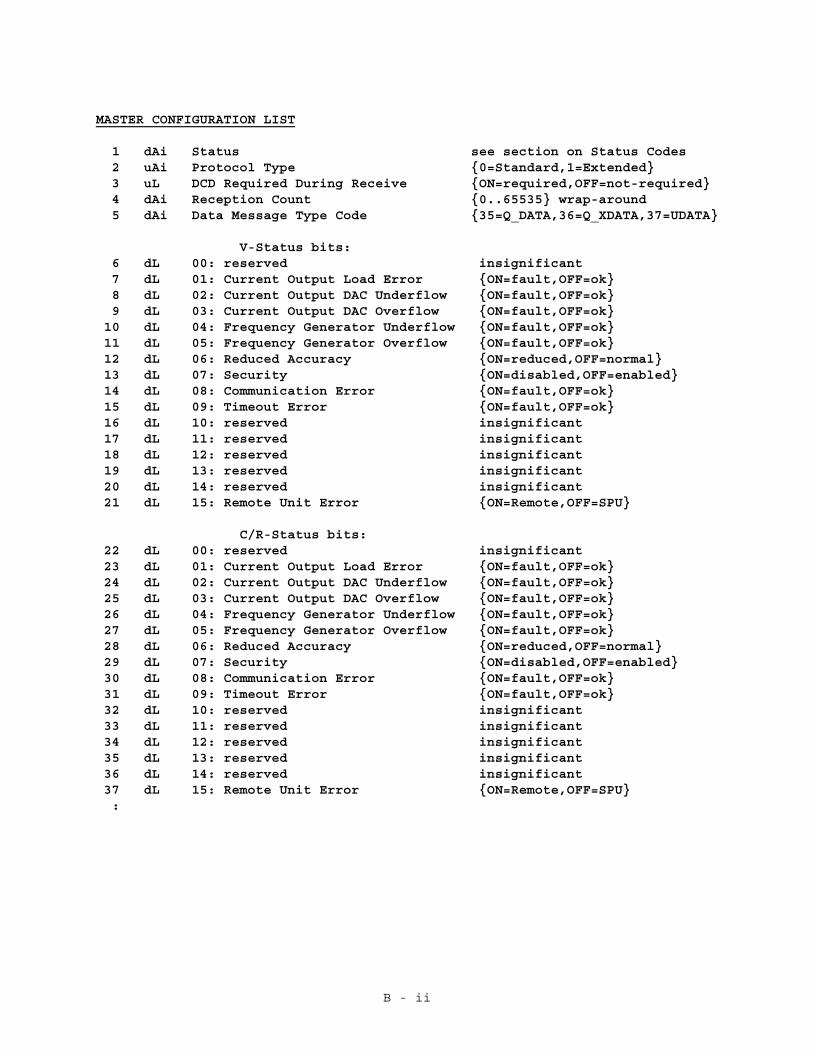
MASTER CONFIGURATION LIST
1 dAi Status see section on Status Codes 2 uAi Protocol Type {0=Standard,1=Extended} 3 uL DCD Required During Receive {ON=required,OFF=not-required} 4 dAi Reception Count {0..65535} wrap-around 5 dAi Data Message Type Code {35=Q_DATA,36=Q_XDATA,37=UDATA}
V-Status bits: 6 dL 00: reserved insignificant 7 dL 01: Current Output Load Error {ON=fault,OFF=ok} 8 dL 02: Current Output DAC Underflow {ON=fault,OFF=ok} 9 dL 03: Current Output DAC Overflow {ON=fault,OFF=ok} 10 dL 04: Frequency Generator Underflow {ON=fault,OFF=ok} 11 dL 05: Frequency Generator Overflow {ON=fault,OFF=ok} 12 dL 06: Reduced Accuracy {ON=reduced,OFF=normal} 13 dL 07: Security {ON=disabled,OFF=enabled} 14 dL 08: Communication Error {ON=fault,OFF=ok} 15 dL 09: Timeout Error {ON=fault,OFF=ok} 16 dL 10: reserved insignificant 17 dL 11: reserved insignificant 18 dL 12: reserved insignificant 19 dL 13: reserved insignificant 20 dL 14: reserved insignificant 21 dL 15: Remote Unit Error {ON=Remote,OFF=SPU}
C/R-Status bits: 22 dL 00: reserved insignificant 23 dL 01: Current Output Load Error {ON=fault,OFF=ok} 24 dL 02: Current Output DAC Underflow {ON=fault,OFF=ok} 25 dL 03: Current Output DAC Overflow {ON=fault,OFF=ok} 26 dL 04: Frequency Generator Underflow {ON=fault,OFF=ok} 27 dL 05: Frequency Generator Overflow {ON=fault,OFF=ok} 28 dL 06: Reduced Accuracy {ON=reduced,OFF=normal} 29 dL 07: Security {ON=disabled,OFF=enabled} 30 dL 08: Communication Error {ON=fault,OFF=ok} 31 dL 09: Timeout Error {ON=fault,OFF=ok} 32 dL 10: reserved insignificant 33 dL 11: reserved insignificant 34 dL 12: reserved insignificant 35 dL 13: reserved insignificant 36 dL 14: reserved insignificant 37 dL 15: Remote Unit Error {ON=Remote,OFF=SPU} :

B - iii
: 38 dAi Quantity of Acoustic Paths (N) {1,2,3,5} 39 dAi Quantity of Samples Taken {0..65535} 40 dAi Path 1: Quantity of Valid Samples {0..65535} 41 dAi Path 2: Quantity of Valid Samples {0..65535} 42 dAi Path 3: Quantity of Valid Samples {0..65535} 43 dAi Path 4: Quantity of Valid Samples {0..65535} 44 dAi Path 5: Quantity of Valid Samples {0..65535} 45 dAi Path 1, Transducer A: AGC Level {0..65535} 46 dAi Path 1, Transducer B: AGC Level {0..65535} 47 dAi Path 2, Transducer A: AGC Level {0..65535} 48 dAi Path 2, Transducer B: AGC Level {0..65535} 49 dAi Path 3, Transducer A: AGC Level {0..65535} 50 dAi Path 3, Transducer B: AGC Level {0..65535} 51 dAi Path 4, Transducer A: AGC Level {0..65535} 52 dAi Path 4, Transducer B: AGC Level {0..65535} 53 dAi Path 5, Transducer A: AGC Level {0..65535} 54 dAi Path 5, Transducer B: AGC Level {0..65535} 55 dAi Path 1, Transducer A: AGC Limit {0..65535} 56 dAi Path 1, Transducer B: AGC Limit {0..65535} 57 dAi Path 2, Transducer A: AGC Limit {0..65535} 58 dAi Path 2, Transducer B: AGC Limit {0..65535} 59 dAi Path 3, Transducer A: AGC Limit {0..65535} 60 dAi Path 3, Transducer B: AGC Limit {0..65535} 61 dAi Path 4, Transducer A: AGC Limit {0..65535} 62 dAi Path 4, Transducer B: AGC Limit {0..65535} 63 dAi Path 5, Transducer A: AGC Limit {0..65535} 64 dAi Path 5, Transducer B: AGC Limit {0..65535} 65 dA (Corrected) Speed of Sound {±3.4e±38} m/s 66 dA (Corrected) Gas Velocity {±3.4e±38} m/s 67 dA Pressure {±3.4e±38} kPa 68 dA Temperature {±3.4e±38} K 69 dA Flow Rate - Line (Operating) {±3.4e±38} m3/h 70 dA Flow Rate - Base (Reference) {±3.4e±38} m3/h 71 dAi Stability {-32768..32767}
72 dA Path 1: Cpp (uncor. speed of sound) {±3.4e±38} m/s 73 dA Path 2: Cpp (uncor. speed of sound) {±3.4e±38} m/s 74 dA Path 3: Cpp (uncor. speed of sound) {±3.4e±38} m/s 75 dA Path 4: Cpp (uncor. speed of sound) {±3.4e±38} m/s 76 dA Path 5: Cpp (uncor. speed of sound) {±3.4e±38} m/s 77 dA Path 1: Vpp (uncor. gas velocity) {±3.4e±38} m/s 78 dA Path 2: Vpp (uncor. gas velocity) {±3.4e±38} m/s 79 dA Path 3: Vpp (uncor. gas velocity) {±3.4e±38} m/s 80 dA Path 4: Vpp (uncor. gas velocity) {±3.4e±38} m/s 81 dA Path 5: Vpp (uncor. gas velocity) {±3.4e±38} m/s
:

B - iv
: 82 dA Meter Type {0..65535} 83 dA Sequence Number {0..4294967295} * 84 dA Forward [Error] Volume {±3.4e±38} m3
85 dA Reverse [Error] Volume {±3.4e±38} m3
86 dA Tspare (for future TwinSonic) {±3.4e±38} 87 dL 00: Path 1 Diagnostic Bit 00 reserved 88 dL 01: Path 1 Diagnostic Bit 01 reserved 89 dL 02: Path 1 Diagnostic Bit 02 reserved 90 dL 03: Path 1 Trans A AGC Level Status {ON=clipped,OFF=normal} 91 dL 04: Path 1 Diagnostic Bit 04 reserved 92 dL 05: Path 1 Diagnostic Bit 05 reserved 93 dL 06: Path 1 Diagnostic Bit 06 reserved 94 dL 07: Path 1 Trans B AGC Level Status {ON=clipped,OFF=normal} 95 dL 08: Path 1 Speed of Sound Status {ON=out-of-range,OFF= normal} 96 dL 09: Path 1 Gas Velocity Status {ON=out-of-range,OFF= normal} 97 dL 10: Path 1 Diagnostic Bit 10 reserved 98 dL 11: Path 1 Performance Status {ON=low,OFF=normal} 99 dL 12: Path 1 Diagnostic Bit 12 reserved100 dL 13: Path 1 Diagnostic Bit 13 reserved101 dL 14: Path 1 Diagnostic Bit 14 reserved102 dL 15: Path 1 Diagnostic Bit 15 reserved103 dL 00: Path 2 Diagnostic Bit 00 reserved104 dL 01: Path 2 Diagnostic Bit 01 reserved105 dL 02: Path 2 Diagnostic Bit 02 reserved106 dL 03: Path 2 Trans A AGC Level Status {ON=clipped,OFF=normal}107 dL 04: Path 2 Diagnostic Bit 04 reserved108 dL 05: Path 2 Diagnostic Bit 05 reserved109 dL 06: Path 2 Diagnostic Bit 06 reserved110 dL 07: Path 2 Trans B AGC Level Status {ON=clipped,OFF=normal}111 dL 08: Path 2 Speed of Sound Status {ON=out-of-range,OFF= normal}112 dL 09: Path 2 Gas Velocity Status {ON=out-of-range,OFF= normal}113 dL 10: Path 2 Diagnostic Bit 10 reserved114 dL 11: Path 2 Performance Status {ON=low,OFF=normal}115 dL 12: Path 2 Diagnostic Bit 12 reserved116 dL 13: Path 2 Diagnostic Bit 13 reserved117 dL 14: Path 2 Diagnostic Bit 14 reserved118 dL 15: Path 2 Diagnostic Bit 15 reserved119 dL 00: Path 3 Diagnostic Bit 00 reserved120 dL 01: Path 3 Diagnostic Bit 01 reserved121 dL 02: Path 3 Diagnostic Bit 02 reserved122 dL 03: Path 3 Trans A AGC Level Status {ON=clipped,OFF=normal}123 dL 04: Path 3 Diagnostic Bit 04 reserved124 dL 05: Path 3 Diagnostic Bit 05 reserved125 dL 06: Path 3 Diagnostic Bit 06 reserved126 dL 07: Path 3 Trans B AGC Level Status {ON=clipped,OFF=normal}127 dL 08: Path 3 Speed of Sound Status {ON=out-of-range,OFF= normal}128 dL 09: Path 3 Gas Velocity Status {ON=out-of-range,OFF= normal}129 dL 10: Path 3 Diagnostic Bit 10 reserved130 dL 11: Path 3 Performance Status {ON=low,OFF=normal} :

B - v
:131 dL 12: Path 3 Diagnostic Bit 12 reserved132 dL 13: Path 3 Diagnostic Bit 13 reserved133 dL 14: Path 3 Diagnostic Bit 14 reserved134 dL 15: Path 3 Diagnostic Bit 15 reserved135 dL 00: Path 4 Diagnostic Bit 00 reserved136 dL 01: Path 4 Diagnostic Bit 01 reserved137 dL 02: Path 4 Diagnostic Bit 02 reserved138 dL 03: Path 4 Trans A AGC Level Status {ON=clipped,OFF=normal}139 dL 04: Path 4 Diagnostic Bit 04 reserved140 dL 05: Path 4 Diagnostic Bit 05 reserved141 dL 06: Path 4 Diagnostic Bit 06 reserved142 dL 07: Path 4 Trans B AGC Level Status {ON=clipped,OFF=normal}143 dL 08: Path 4 Speed of Sound Status {ON=out-of-range,OFF=normal}144 dL 09: Path 4 Gas Velocity Status {ON=out-of-range,OFF=normal}145 dL 10: Path 4 Diagnostic Bit 10 reserved146 dL 11: Path 4 Performance Status {ON=low,OFF=normal}147 dL 12: Path 4 Diagnostic Bit 12 reserved148 dL 13: Path 4 Diagnostic Bit 13 reserved149 dL 14: Path 4 Diagnostic Bit 14 reserved150 dL 15: Path 4 Diagnostic Bit 15 reserved151 dL 00: Path 5 Diagnostic Bit 00 reserved152 dL 01: Path 5 Diagnostic Bit 01 reserved153 dL 02: Path 5 Diagnostic Bit 02 reserved154 dL 03: Path 5 Trans A AGC Level Status {ON=clipped,OFF=normal}155 dL 04: Path 5 Diagnostic Bit 04 reserved156 dL 05: Path 5 Diagnostic Bit 05 reserved157 dL 06: Path 5 Diagnostic Bit 06 reserved158 dL 07: Path 5 Trans B AGC Level Status {ON=clipped,OFF=normal}159 dL 08: Path 5 Speed of Sound Status {ON=out-of-range,OFF= normal}160 dL 09: Path 5 Gas Velocity Status {ON=out-of-range,OFF= normal}161 dL 10: Path 5 Diagnostic Bit 10 reserved162 dL 11: Path 5 Performance Status {ON=low,OFF=normal}163 dL 12: Path 5 Diagnostic Bit 12 reserved164 dL 13: Path 5 Diagnostic Bit 13 reserved165 dL 14: Path 5 Diagnostic Bit 14 reserved166 dL 15: Path 5 Diagnostic Bit 15 reserved

B - vi
TEST DIAGNOSTICS LIST
1 dAi Status {0,-1XXXX} see Status Codes 2 dS Last Received Message size 64 -> {0..21} msg chars 3 dAi Buffer Length {0..255} 4 dAi Length in Message {0..253} 5 dS 1st Part of Received Message size 64 6 dS 2nd Part of Received Message size 64 7 dS 3rd Part of Received Message size 64 8 dS 4th Part of Received Message size 64 9 dS 5th Part of Received Message size 64 10 dS 6th Part of Received Message size 64 11 dS 7th Part of Received Message size 64 12 dS 8th Part of Received Message size 64 13 dS 9th Part of Received Message size 64 14 dS 10th Part of Received Message size 64 15 dS 11th Part of Received Message size 64 16 dS 12th Part of Received Message size 64 17 dS 13th Part of Received Message size 64 18 dS 14th Part of Received Message size 64 19 dS 15th Part of Received Message size 64 20 dS 16th Part of Received Message size 64 21 dS 17th Part of Received Message size 64 22 dS 18th Part of Received Message size 64 23 dS 19th Part of Received Message size 64 24 dS 20th Part of Received Message size 64 25 dS Checksum Result size 64 26 dS Syntax Check Result size 64 27 dS Syntax Error Result size 64

C - i
APPENDIX C: RECEIVED MESSAGE DIAGNOSTICS
The following diagrams show the contents of the Test Diagnostic Nth Part ofReceived Message signals, one diagram per CODE:PATH combination.
CODE 37 0 1 2 3 45 PATHS 012345678901234567890123456789012345678901234567
1st Part Cd Vstat CRsta QPath QSamp ~~ ~~ ~~ ~~ ~~ ~~ ~~ ~~ ~~2nd Part ValS1 ValS2 ValS3 ValS4 ValS5 ~~ ~~ ~~ ~~ ~~ ~~ ~~ ~~ ~~ ~~3rd Part Lev1A Lev1B Lev2A Lev2B ~~ ~~ ~~ ~~ ~~ ~~ ~~ ~~4th Part Lev3A Lev3B Lev4A Lev4B ~~ ~~ ~~ ~~ ~~ ~~ ~~ ~~5th Part Lev5A Lev5B Lim1A Lim1B ~~ ~~ ~~ ~~ ~~ ~~ ~~ ~~6th Part Lim2A Lim2B Lim3A Lim3B ~~ ~~ ~~ ~~ ~~ ~~ ~~ ~~7th Part Lim4A Lim4B Lim5A Lim5B ~~ ~~ ~~ ~~ ~~ ~~ ~~ ~~8th Part Speed-Sound GasVelocity -Pressure-- ~~ ~~ ~~ ~~ ~~ ~~ ~~ ~~ ~~ ~~ ~~ ~~9th Part Temperature LineFloRate BaseFloRate ~~ ~~ ~~ ~~ ~~ ~~ ~~ ~~ ~~ ~~ ~~ ~~10th Part Stabi ~~ ~~11th Part CppForPath1 CppForPath2 CppForPath3 ~~ ~~ ~~ ~~ ~~ ~~ ~~ ~~ ~~ ~~ ~~ ~~12th Part CppForPath4 CppForPath5 ~~ ~~ ~~ ~~ ~~ ~~ ~~ ~~13th Part VppForPath1 VppForPath2 VppForPath3 ~~ ~~ ~~ ~~ ~~ ~~ ~~ ~~ ~~ ~~ ~~ ~~14th Part VppForPath4 VppForPath5 ~~ ~~ ~~ ~~ ~~ ~~ ~~ ~~15th Part MType SequenceNum ~~ ~~ ~~ ~~ ~~ ~~16th Part Forward-Vol Reverse-Vol TSonicSpare ~~ ~~ ~~ ~~ ~~ ~~ ~~ ~~ ~~ ~~ ~~ ~~17th Part Diag1 Diag2 Diag3 Diag4 Diag5 ~~ ~~ ~~ ~~ ~~ ~~ ~~ ~~ ~~ ~~ 012345678901234567890123456789012345678901234567 0 1 2 3 4

C - ii
CODE 37 0 1 2 3 43 PATHS 012345678901234567890123456789012345678901234567
1st Part Cd Vstat CRsta QPath QSamp ~~ ~~ ~~ ~~ ~~ ~~ ~~ ~~ ~~2nd Part ValS1 ValS2 ValS3 -- -- -- -- ~~ ~~ ~~ ~~ ~~ ~~ ~~ ~~ ~~ ~~3rd Part Lev1A Lev1B Lev2A Lev2B ~~ ~~ ~~ ~~ ~~ ~~ ~~ ~~4th Part Lev3A Lev3B -- -- -- -- ~~ ~~ ~~ ~~ ~~ ~~ ~~ ~~5th Part -- -- -- -- Lim1A Lim1B ~~ ~~ ~~ ~~ ~~ ~~ ~~ ~~6th Part Lim2A Lim2B Lim3A Lim3B ~~ ~~ ~~ ~~ ~~ ~~ ~~ ~~7th Part -- -- -- -- -- -- -- -- ~~ ~~ ~~ ~~ ~~ ~~ ~~ ~~8th Part Speed-Sound GasVelocity -Pressure-- ~~ ~~ ~~ ~~ ~~ ~~ ~~ ~~ ~~ ~~ ~~ ~~9th Part Temperature LineFloRate BaseFloRate ~~ ~~ ~~ ~~ ~~ ~~ ~~ ~~ ~~ ~~ ~~ ~~10th Part Stabi ~~ ~~11th Part CppForPath1 CppForPath2 CppForPath3 ~~ ~~ ~~ ~~ ~~ ~~ ~~ ~~ ~~ ~~ ~~ ~~12th Part -- -- -- -- -- -- -- -- ~~ ~~ ~~ ~~ ~~ ~~ ~~ ~~13th Part VppForPath1 VppForPath2 VppForPath3 ~~ ~~ ~~ ~~ ~~ ~~ ~~ ~~ ~~ ~~ ~~ ~~14th Part -- -- -- -- -- -- -- -- ~~ ~~ ~~ ~~ ~~ ~~ ~~ ~~15th Part MType SequenceNum ~~ ~~ ~~ ~~ ~~ ~~16th Part Forward-Vol Reverse-Vol TSonicSpare ~~ ~~ ~~ ~~ ~~ ~~ ~~ ~~ ~~ ~~ ~~ ~~17th Part Diag1 Diag2 Diag3 -- -- -- -- ~~ ~~ ~~ ~~ ~~ ~~ ~~ ~~ ~~ ~~ 012345678901234567890123456789012345678901234567 0 1 2 3 4

C - iii
CODE 37 0 1 2 3 42 PATHS 012345678901234567890123456789012345678901234567
1st Part Cd Vstat CRsta QPath QSamp ~~ ~~ ~~ ~~ ~~ ~~ ~~ ~~ ~~2nd Part ValS1 ValS2 ValS3 -- -- -- -- ~~ ~~ ~~ ~~ ~~ ~~ ~~ ~~ ~~ ~~3rd Part Lev1A Lev1B Lev2A Lev2B ~~ ~~ ~~ ~~ ~~ ~~ ~~ ~~4th Part -- -- -- -- -- -- -- -- ~~ ~~ ~~ ~~ ~~ ~~ ~~ ~~5th Part -- -- -- -- Lim1A Lim1B ~~ ~~ ~~ ~~ ~~ ~~ ~~ ~~6th Part Lim2A Lim2B -- -- -- -- ~~ ~~ ~~ ~~ ~~ ~~ ~~ ~~7th Part -- -- -- -- -- -- -- -- ~~ ~~ ~~ ~~ ~~ ~~ ~~ ~~8th Part Speed-Sound GasVelocity -Pressure-- ~~ ~~ ~~ ~~ ~~ ~~ ~~ ~~ ~~ ~~ ~~ ~~9th Part Temperature LineFloRate BaseFloRate ~~ ~~ ~~ ~~ ~~ ~~ ~~ ~~ ~~ ~~ ~~ ~~10th Part Stabi ~~ ~~11th Part CppForPath1 CppForPath2 -- -- -- -- ~~ ~~ ~~ ~~ ~~ ~~ ~~ ~~ ~~ ~~ ~~ ~~12th Part -- -- -- -- -- -- -- -- ~~ ~~ ~~ ~~ ~~ ~~ ~~ ~~13th Part VppForPath1 VppForPath2 -- -- -- -- ~~ ~~ ~~ ~~ ~~ ~~ ~~ ~~ ~~ ~~ ~~ ~~14th Part -- -- -- -- -- -- -- -- ~~ ~~ ~~ ~~ ~~ ~~ ~~ ~~15th Part MType SequenceNum ~~ ~~ ~~ ~~ ~~ ~~16th Part Forward-Vol Reverse-Vol TSonicSpare ~~ ~~ ~~ ~~ ~~ ~~ ~~ ~~ ~~ ~~ ~~ ~~17th Part Diag1 Diag2 -- -- -- -- -- -- ~~ ~~ ~~ ~~ ~~ ~~ ~~ ~~ ~~ ~~ 012345678901234567890123456789012345678901234567 0 1 2 3 4

C - iv
CODE 37 0 1 2 3 41 PATH 012345678901234567890123456789012345678901234567
1st Part Cd Vstat CRsta QPath QSamp ~~ ~~ ~~ ~~ ~~ ~~ ~~ ~~ ~~2nd Part ValS1 ValS2 ValS3 -- -- -- -- ~~ ~~ ~~ ~~ ~~ ~~ ~~ ~~ ~~ ~~3rd Part Lev1A Lev1B -- -- -- -- ~~ ~~ ~~ ~~ ~~ ~~ ~~ ~~4th Part -- -- -- -- -- -- -- -- ~~ ~~ ~~ ~~ ~~ ~~ ~~ ~~5th Part -- -- -- -- Lim1A Lim1B ~~ ~~ ~~ ~~ ~~ ~~ ~~ ~~6th Part -- -- -- -- -- -- -- -- ~~ ~~ ~~ ~~ ~~ ~~ ~~ ~~7th Part -- -- -- -- -- -- -- -- ~~ ~~ ~~ ~~ ~~ ~~ ~~ ~~8th Part Speed-Sound GasVelocity -Pressure-- ~~ ~~ ~~ ~~ ~~ ~~ ~~ ~~ ~~ ~~ ~~ ~~9th Part Temperature LineFloRate BaseFloRate ~~ ~~ ~~ ~~ ~~ ~~ ~~ ~~ ~~ ~~ ~~ ~~10th Part Stabi ~~ ~~11th Part CppForPath1 -- -- -- -- -- -- -- -- ~~ ~~ ~~ ~~ ~~ ~~ ~~ ~~ ~~ ~~ ~~ ~~12th Part -- -- -- -- -- -- -- -- ~~ ~~ ~~ ~~ ~~ ~~ ~~ ~~13th Part VppForPath1 -- -- -- -- -- -- -- -- ~~ ~~ ~~ ~~ ~~ ~~ ~~ ~~ ~~ ~~ ~~ ~~14th Part -- -- -- -- -- -- -- -- ~~ ~~ ~~ ~~ ~~ ~~ ~~ ~~15th Part MType SequenceNum ~~ ~~ ~~ ~~ ~~ ~~16th Part Forward-Vol Reverse-Vol TSonicSpare ~~ ~~ ~~ ~~ ~~ ~~ ~~ ~~ ~~ ~~ ~~ ~~17th Part Diag1 -- -- -- -- -- -- -- -- ~~ ~~ ~~ ~~ ~~ ~~ ~~ ~~ ~~ ~~ 012345678901234567890123456789012345678901234567 0 1 2 3 4

C - v
CODE 36 0 1 2 3 45 PATHS 012345678901234567890123456789012345678901234567
1st Part Cd Vstat CRsta QPath QSamp ~~ ~~ ~~ ~~ ~~ ~~ ~~ ~~ ~~2nd Part ValS1 ValS2 ValS3 ValS4 ValS5 ~~ ~~ ~~ ~~ ~~ ~~ ~~ ~~ ~~ ~~3rd Part Lev1A Lev1B Lev2A Lev2B ~~ ~~ ~~ ~~ ~~ ~~ ~~ ~~4th Part Lev3A Lev3B Lev4A Lev4B ~~ ~~ ~~ ~~ ~~ ~~ ~~ ~~5th Part Lev5A Lev5B Lim1A Lim1B ~~ ~~ ~~ ~~ ~~ ~~ ~~ ~~6th Part Lim2A Lim2B Lim3A Lim3B ~~ ~~ ~~ ~~ ~~ ~~ ~~ ~~7th Part Lim4A Lim4B Lim5A Lim5B ~~ ~~ ~~ ~~ ~~ ~~ ~~ ~~8th Part Speed-Sound GasVelocity -Pressure-- ~~ ~~ ~~ ~~ ~~ ~~ ~~ ~~ ~~ ~~ ~~ ~~9th Part Temperature LineFloRate BaseFloRate ~~ ~~ ~~ ~~ ~~ ~~ ~~ ~~ ~~ ~~ ~~ ~~10th Part Stabi ~~ ~~11th Part CppForPath1 CppForPath2 CppForPath3 ~~ ~~ ~~ ~~ ~~ ~~ ~~ ~~ ~~ ~~ ~~ ~~12th Part CppForPath4 CppForPath5 ~~ ~~ ~~ ~~ ~~ ~~ ~~ ~~13th Part VppForPath1 VppForPath2 VppForPath3 ~~ ~~ ~~ ~~ ~~ ~~ ~~ ~~ ~~ ~~ ~~ ~~14th Part VppForPath4 VppForPath5 ~~ ~~ ~~ ~~ ~~ ~~ ~~ ~~15th Part -- -- -- -- -- -- ~~ ~~ ~~ ~~ ~~ ~~16th Part -- -- -- -- -- -- -- -- -- -- -- -- ~~ ~~ ~~ ~~ ~~ ~~ ~~ ~~ ~~ ~~ ~~ ~~17th Part -- -- -- -- -- -- -- -- -- -- ~~ ~~ ~~ ~~ ~~ ~~ ~~ ~~ ~~ ~~ 012345678901234567890123456789012345678901234567 0 1 2 3 4

C - vi
CODE 36 0 1 2 3 43 PATHS 012345678901234567890123456789012345678901234567
1st Part Cd Vstat CRsta QPath QSamp ~~ ~~ ~~ ~~ ~~ ~~ ~~ ~~ ~~2nd Part ValS1 ValS2 ValS3 -- -- -- -- ~~ ~~ ~~ ~~ ~~ ~~ ~~ ~~ ~~ ~~3rd Part Lev1A Lev1B Lev2A Lev2B ~~ ~~ ~~ ~~ ~~ ~~ ~~ ~~4th Part Lev3A Lev3B -- -- -- -- ~~ ~~ ~~ ~~ ~~ ~~ ~~ ~~5th Part -- -- -- -- Lim1A Lim1B ~~ ~~ ~~ ~~ ~~ ~~ ~~ ~~6th Part Lim2A Lim2B Lim3A Lim3B ~~ ~~ ~~ ~~ ~~ ~~ ~~ ~~7th Part -- -- -- -- -- -- -- -- ~~ ~~ ~~ ~~ ~~ ~~ ~~ ~~8th Part Speed-Sound GasVelocity -Pressure-- ~~ ~~ ~~ ~~ ~~ ~~ ~~ ~~ ~~ ~~ ~~ ~~9th Part Temperature LineFloRate BaseFloRate ~~ ~~ ~~ ~~ ~~ ~~ ~~ ~~ ~~ ~~ ~~ ~~10th Part Stabi ~~ ~~11th Part CppForPath1 CppForPath2 CppForPath3 ~~ ~~ ~~ ~~ ~~ ~~ ~~ ~~ ~~ ~~ ~~ ~~12th Part -- -- -- -- -- -- -- -- ~~ ~~ ~~ ~~ ~~ ~~ ~~ ~~13th Part VppForPath1 VppForPath2 VppForPath3 ~~ ~~ ~~ ~~ ~~ ~~ ~~ ~~ ~~ ~~ ~~ ~~14th Part -- -- -- -- -- -- -- -- ~~ ~~ ~~ ~~ ~~ ~~ ~~ ~~15th Part -- -- -- -- -- -- ~~ ~~ ~~ ~~ ~~ ~~16th Part -- -- -- -- -- -- -- -- -- -- -- -- ~~ ~~ ~~ ~~ ~~ ~~ ~~ ~~ ~~ ~~ ~~ ~~17th Part -- -- -- -- -- -- -- -- -- -- ~~ ~~ ~~ ~~ ~~ ~~ ~~ ~~ ~~ ~~ 012345678901234567890123456789012345678901234567 0 1 2 3 4
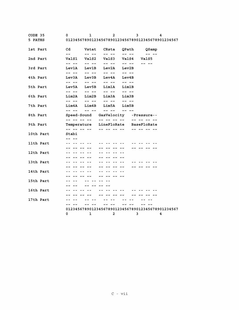
C - vii
CODE 35 0 1 2 3 45 PATHS 012345678901234567890123456789012345678901234567
1st Part Cd Vstat CRsta QPath QSamp ~~ ~~ ~~ ~~ ~~ ~~ ~~ ~~ ~~2nd Part ValS1 ValS2 ValS3 ValS4 ValS5 ~~ ~~ ~~ ~~ ~~ ~~ ~~ ~~ ~~ ~~3rd Part Lev1A Lev1B Lev2A Lev2B ~~ ~~ ~~ ~~ ~~ ~~ ~~ ~~4th Part Lev3A Lev3B Lev4A Lev4B ~~ ~~ ~~ ~~ ~~ ~~ ~~ ~~5th Part Lev5A Lev5B Lim1A Lim1B ~~ ~~ ~~ ~~ ~~ ~~ ~~ ~~6th Part Lim2A Lim2B Lim3A Lim3B ~~ ~~ ~~ ~~ ~~ ~~ ~~ ~~7th Part Lim4A Lim4B Lim5A Lim5B ~~ ~~ ~~ ~~ ~~ ~~ ~~ ~~8th Part Speed-Sound GasVelocity -Pressure-- ~~ ~~ ~~ ~~ ~~ ~~ ~~ ~~ ~~ ~~ ~~ ~~9th Part Temperature LineFloRate BaseFloRate ~~ ~~ ~~ ~~ ~~ ~~ ~~ ~~ ~~ ~~ ~~ ~~10th Part Stabi ~~ ~~11th Part -- -- -- -- -- -- -- -- -- -- -- -- ~~ ~~ ~~ ~~ ~~ ~~ ~~ ~~ ~~ ~~ ~~ ~~12th Part -- -- -- -- -- -- -- -- ~~ ~~ ~~ ~~ ~~ ~~ ~~ ~~13th Part -- -- -- -- -- -- -- -- -- -- -- -- ~~ ~~ ~~ ~~ ~~ ~~ ~~ ~~ ~~ ~~ ~~ ~~14th Part -- -- -- -- -- -- -- -- ~~ ~~ ~~ ~~ ~~ ~~ ~~ ~~15th Part -- -- -- -- -- -- ~~ ~~ ~~ ~~ ~~ ~~16th Part -- -- -- -- -- -- -- -- -- -- -- -- ~~ ~~ ~~ ~~ ~~ ~~ ~~ ~~ ~~ ~~ ~~ ~~17th Part -- -- -- -- -- -- -- -- -- -- ~~ ~~ ~~ ~~ ~~ ~~ ~~ ~~ ~~ ~~ 012345678901234567890123456789012345678901234567 0 1 2 3 4

C - viii
CODE 35 0 1 2 3 43 PATHS 012345678901234567890123456789012345678901234567
1st Part Cd Vstat CRsta QPath QSamp ~~ ~~ ~~ ~~ ~~ ~~ ~~ ~~ ~~2nd Part ValS1 ValS2 ValS3 -- -- -- -- ~~ ~~ ~~ ~~ ~~ ~~ ~~ ~~ ~~ ~~3rd Part Lev1A Lev1B Lev2A Lev2B ~~ ~~ ~~ ~~ ~~ ~~ ~~ ~~4th Part Lev3A Lev3B -- -- -- -- ~~ ~~ ~~ ~~ ~~ ~~ ~~ ~~5th Part -- -- -- -- Lim1A Lim1B ~~ ~~ ~~ ~~ ~~ ~~ ~~ ~~6th Part Lim2A Lim2B Lim3A Lim3B ~~ ~~ ~~ ~~ ~~ ~~ ~~ ~~7th Part -- -- -- -- -- -- -- -- ~~ ~~ ~~ ~~ ~~ ~~ ~~ ~~8th Part Speed-Sound GasVelocity -Pressure-- ~~ ~~ ~~ ~~ ~~ ~~ ~~ ~~ ~~ ~~ ~~ ~~9th Part Temperature LineFloRate BaseFloRate ~~ ~~ ~~ ~~ ~~ ~~ ~~ ~~ ~~ ~~ ~~ ~~10th Part Stabi ~~ ~~11th Part -- -- -- -- -- -- -- -- -- -- -- -- ~~ ~~ ~~ ~~ ~~ ~~ ~~ ~~ ~~ ~~ ~~ ~~12th Part -- -- -- -- -- -- -- -- ~~ ~~ ~~ ~~ ~~ ~~ ~~ ~~13th Part -- -- -- -- -- -- -- -- -- -- -- -- ~~ ~~ ~~ ~~ ~~ ~~ ~~ ~~ ~~ ~~ ~~ ~~14th Part -- -- -- -- -- -- -- -- ~~ ~~ ~~ ~~ ~~ ~~ ~~ ~~15th Part -- -- -- -- -- -- ~~ ~~ ~~ ~~ ~~ ~~16th Part -- -- -- -- -- -- -- -- -- -- -- -- ~~ ~~ ~~ ~~ ~~ ~~ ~~ ~~ ~~ ~~ ~~ ~~17th Part -- -- -- -- -- -- -- -- -- -- ~~ ~~ ~~ ~~ ~~ ~~ ~~ ~~ ~~ ~~ 012345678901234567890123456789012345678901234567 0 1 2 3 4

C - ix
CODE 35 0 1 2 3 41 PATH 012345678901234567890123456789012345678901234567
1st Part Cd Vstat CRsta QPath QSamp ~~ ~~ ~~ ~~ ~~ ~~ ~~ ~~ ~~2nd Part ValS1 ValS2 ValS3 -- -- -- -- ~~ ~~ ~~ ~~ ~~ ~~ ~~ ~~ ~~ ~~3rd Part Lev1A Lev1B -- -- -- -- ~~ ~~ ~~ ~~ ~~ ~~ ~~ ~~4th Part -- -- -- -- -- -- -- -- ~~ ~~ ~~ ~~ ~~ ~~ ~~ ~~5th Part -- -- -- -- Lim1A Lim1B ~~ ~~ ~~ ~~ ~~ ~~ ~~ ~~6th Part -- -- -- -- -- -- -- -- ~~ ~~ ~~ ~~ ~~ ~~ ~~ ~~7th Part -- -- -- -- -- -- -- -- ~~ ~~ ~~ ~~ ~~ ~~ ~~ ~~8th Part Speed-Sound GasVelocity -Pressure-- ~~ ~~ ~~ ~~ ~~ ~~ ~~ ~~ ~~ ~~ ~~ ~~9th Part Temperature LineFloRate BaseFloRate ~~ ~~ ~~ ~~ ~~ ~~ ~~ ~~ ~~ ~~ ~~ ~~10th Part Stabi ~~ ~~11th Part -- -- -- -- -- -- -- -- -- -- -- -- ~~ ~~ ~~ ~~ ~~ ~~ ~~ ~~ ~~ ~~ ~~ ~~12th Part -- -- -- -- -- -- -- -- ~~ ~~ ~~ ~~ ~~ ~~ ~~ ~~13th Part -- -- -- -- -- -- -- -- -- -- -- -- ~~ ~~ ~~ ~~ ~~ ~~ ~~ ~~ ~~ ~~ ~~ ~~14th Part -- -- -- -- -- -- -- -- ~~ ~~ ~~ ~~ ~~ ~~ ~~ ~~15th Part -- -- -- -- -- -- ~~ ~~ ~~ ~~ ~~ ~~16th Part -- -- -- -- -- -- -- -- -- -- -- -- ~~ ~~ ~~ ~~ ~~ ~~ ~~ ~~ ~~ ~~ ~~ ~~17th Part -- -- -- -- -- -- -- -- -- -- ~~ ~~ ~~ ~~ ~~ ~~ ~~ ~~ ~~ ~~ 012345678901234567890123456789012345678901234567 0 1 2 3 4

D - i
APPENDIX D: RECEIVED MESSAGE VS. DATA SIGNALS
The following tables show the Received Message Fields, with DATA TYPE andSIZE, vs. Test Diagnostics List Nth PART of Received Message Signals’ Contents(with COLumn number therein) for valid combinations of CODES:PATHS, onediagram per QTY of PATHS.
For each field, the table lists its Start OFFset within the received message"Information" field, and the corresponding [USED] and <UNUSED> Data Signalnumbers.
N = quantity of acoustic paths
chr = character (unsigned 8-bit integer)uns = unsigned (16-bit integer)int = signed (16-bit integer)lng = long (signed 32-bit integer)flt = float (IEEE-754 32-bit floating point)
In ACCOL, all numeric values are float.
RECEIVED DATA DIAG_MSG 35,37 : 1MESSAGE --------- -------- --------------------FIELD TYPE SIZE PART.COL OFF USED UNUSED--------------- --- --- -------- --- ------- -------Code chr 1 1.1 0 [5] \ \Vstatus uns 2 1.2 1 [6-21] | |CRstatus uns 2 1.3 3 [22-37] | |NumPaths int 2 1.4 5 [38] | |SampleRate uns 2 1.5 7 [39] | |ValidSamples[N] uns 2N 2.1-2.5 9 [40] <41-44> | |AgcLevel[N][2] uns 4N 3.1-5.2 11 [45,46] <47-54> | |AgcLimit[N][2] uns 4N 5.3-7.4 15 [55,56] <57-64> | |SpeedOfSound flt 4 8.1 19 [65] | |GasVelocity flt 4 8.2 23 [66] | |Pressure flt 4 8.3 27 [67] | |Temperature flt 4 9.1 31 [68] | |Qline flt 4 9.2 35 [69] | |Qbase flt 4 9.3 39 [70] | |Stability________int__2___10.1________43_[71]_______________|___/ Code 35Cpp[N] flt 4N 11.1-12.2 45 [72] <73-76> |Vpp[N] flt 4N 13.1-14.2 49 [77] <78-81> |MeterType uns 2 15.1 53 [82] |SequenceNum lng 4 15.2 55 [83] |ForwardVolume flt 4 16.1 59 [84] |ReverseVolume flt 4 16.2 63 [85] |Tspare flt 4 16.3 67 [86] |DiagBits[N] uns 2N 17.1-17.5 71 [87-102] <103-166> / Code 37--------------- ---TOTAL: 73

D - ii
RECEIVED DATA DIAG_MSG 37 : 2MESSAGE --------- -------- --------------------FIELD TYPE SIZE PART.COL OFF USED UNUSED--------------- --- --- -------- --- ------- -------Code chr 1 1.1 0 [5]Vstatus uns 2 1.2 1 [6-21]CRstatus uns 2 1.3 3 [22-37]NumPaths int 2 1.4 5 [38]SampleRate uns 2 1.5 7 [39]ValidSamples[N] uns 2N 2.1-2.5 9 [40,41] <42-44>AgcLevel[N][2] uns 4N 3.1-5.2 13 [45-48] <49-54>AgcLimit[N][2] uns 4N 5.3-7.4 21 [55-58] <59-64>SpeedOfSound flt 4 8.1 29 [65]GasVelocity flt 4 8.2 33 [66]Pressure flt 4 8.3 37 [67]Temperature flt 4 9.1 41 [68]Qline flt 4 9.2 45 [69]Qbase flt 4 9.3 49 [70]Stability int 2 10.1 53 [71]Cpp[N] flt 4N 11.1-12.2 55 [72,73] <74-76>Vpp[N] flt 4N 13.1-14.2 63 [77,78] <79-81>MeterType uns 2 15.1 71 [82]SequenceNum lng 4 15.2 73 [83]ForwardVolume flt 4 16.1 77 [84]ReverseVolume flt 4 16.2 81 [85]Tspare flt 4 16.3 85 [86]DiagBits[N] uns 2N 17.1-17.5 89 [87-118] <119-166>--------------- ---TOTAL: 93

D - iii
RECEIVED DATA DIAG_MSG 35,36,37 : 3MESSAGE --------- -------- --------------------FIELD TYPE SIZE PART.COL OFF USED UNUSED--------------- --- --- -------- --- ------- -------Code chr 1 1.1 0 [5] \ \ \Vstatus uns 2 1.2 1 [6-21] | | |CRstatus uns 2 1.3 3 [22-37] | | |NumPaths int 2 1.4 5 [38] | | |SampleRate uns 2 1.5 7 [39] | | |ValidSamples[N] uns 2N 2.1-2.5 9 [40-42] <43,44> | | |AgcLevel[N][2] uns 4N 3.1-5.2 15 [45-50] <51-54> | | |AgcLimit[N][2] uns 4N 5.3-7.4 27 [55-60] <61-64> | | |SpeedOfSound flt 4 8.1 39 [65] | | |GasVelocity flt 4 8.2 43 [66] | | |Pressure flt 4 8.3 47 [67] | | |Temperature flt 4 9.1 51 [68] | | |Qline flt 4 9.2 55 [69] | | |Qbase flt 4 9.3 59 [70] | | |Stability________int__2___10.1________63_[71]_______________|_|_/ Code 35Cpp[N] flt 4N 11.1-12.2 65 [72-74] <75,76> | |Vpp[N]___________flt__4N__13.1-14.2___77_[77-89]__<80,81>___|_/ Code 36MeterType uns 2 15.1 89 [82] |SequenceNum lng 4 15.2 91 [83] |ForwardVolume flt 4 16.1 95 [84] |ReverseVolume flt 4 16.2 99 [85] |Tspare flt 4 16.3 103 [86] |DiagBits[N] uns 2N 17.1-17.5 107 [87-134] <135-166> / Code 37--------------- ---TOTAL: 113

D - iv
RECEIVED DATA DIAG_MSG 35,36,37 : 5MESSAGE --------- -------- ----------FIELD TYPE SIZE PART.COL OFF USED--------------- --- --- -------- --- ------Code chr 1 1.1 0 [5] \ \ \Vstatus uns 2 1.2 1 [6-21] | | |CRstatus uns 2 1.3 3 [22-37] | | |NumPaths int 2 1.4 5 [38] | | |SampleRate uns 2 1.5 7 [39] | | |ValidSamples[N] uns 2N 2.1-2.5 9 [40-44] | | |AgcLevel[N][2] uns 4N 3.1-5.2 19 [45-54] | | |AgcLimit[N][2] uns 4N 5.3-7.4 39 [55-64] | | |SpeedOfSound flt 4 8.1 59 [65] | | |GasVelocity flt 4 8.2 63 [66] | | |Pressure flt 4 8.3 67 [67] | | |Temperature flt 4 9.1 71 [68] | | |Qline flt 4 9.2 75 [69] | | |Qbase flt 4 9.3 79 [70] | | |Stability________int__2___10.1_________83 [71]_______|_|_/ Code 35Cpp[N] flt 4N 11.1-12.2 85 [72-76] | |Vpp[N]___________flt__4N__13.1-14.2___105_[77-81]____|_/ Code 36MeterType uns 2 15.1 125 [82] |SequenceNum lng 4 15.2 127 [83] |ForwardVolume flt 4 16.1 131 [84] |ReverseVolume flt 4 16.2 135 [85] |Tspare flt 4 16.3 139 [86] |DiagBits[N] uns 2N 17.1-17.5 143 [87-166] / Code 37--------------- ---TOTAL: 153

D - v
The following tables show the Test Diagnostics List Nth PART of ReceivedMessage Signals’ Contents (including QTY of columns) for valid combinations ofCODES:PATHS.For Nth PART signal, the table lists the BYTES within the received message"Information" field displayed, and the corresponding [USED] and <UNUSED> DataSignal numbers.
DIAG_MSG 35,37 : 1 37 : 2 <- CODES:PATHS-------- ------------------------ ------------------------PART QTY BYTES USED UNUSED BYTES USED UNUSED---- --- ----- -------- --------- ----- -------- --------- 1st (5) 0-8 [5-39] 0-8 [5-39] \ \ 2nd (5) 9-10 [40] <41-44> 9-12 [40,41] <42-44> | | 3rd (4) 11-14 [45,46] <47,48> 13-20 [45-48] | | 4th (4) <49-52> <49-52> | | 5th (4) 15-18 [55,56] <53,54> 21-24 [55,56] <53,54> | | 6th (4) <57-60> 25-28 [57,58] <59,60> | | 7th (4) <61-64> <61-64> | | 8th (3) 19-30 [65-67] 29-40 [65-67] | | 9th (3) 31-42 [68-70] 41-52 [68-70] | |10th_(1)__43,44_[71]________________53,54_[71]________________|_/ Code 3511th (3) 45-48 [72] <73,74> 55-62 [72,73] <74> |12th (3) <75,76> <75,76> |13th (3) 49-52 [77] <78,79> 63-70 [77,78] <79> |14th (3) <80,81> <80,81> |15th (2) 53-58 [82,83] 71-76 [82,83] |16th (3) 59-70 [84-86] 77-88 [84-86] |17th (5) 71-72 [87-102] <103-166> 89-92 [87-118] <119-166> / Code 37
DIAG_MSG 35,36,37 : 3 35,36,37 : 5 <- CODES:PATHS-------- -------------------------- ----------------PART QTY BYTES USED UNUSED BYTES USED---- --- ------- -------- --------- ------- -------- 1st (5) 0-8 [5-39] 0-8 [5-39] \ \ \ 2nd (5) 9-14 [40-42] <43,44> 9-18 [40-44] | | | 3rd (4) 15-22 [45-48] 19-26 [45-48] | | | 4th (4) 23-26 [49,50] <51,52> 27-34 [49-52] | | | 5th (4) 27-30 [55,56] <53,54> 35-42 [53-56] | | | 6th (4) 31-38 [57-60] 43-50 [57-60] | | | 7th (4) <61-64> 51-58 [61-64] | | | 8th (3) 39-50 [65-67] 59-70 [65-67] | | | 9th (3) 51-62 [68-70] 71-82 [68-70] | | |10th_(1)___63,64___[71]________________83-84 [71]________|_|_/ Code 3511th (3) 65-76 [72-74] 85-96 [72-74] | |12th (3) <75,76> 97-104 [75,76] | |13th (3) 77-88 [77-79] 105-116 [77-79] | |14th (3)___________________<80,81>____117-124_[80,81]_____|_/ Code 3615th (2) 89-94 [82,83] 125-130 [82,83] |16th (3) 95-106 [84-86] 131-142 [84-86] |17th (5) 107-112 [87-166]<135-166> 143-152 [87-166] / Code 37

Return to Application Notes Menu
Return to the List of Manuals