Embed Size (px)
Citation preview

CONGRATULATIONS! The FMI “Q” PUMP LINE is one of the finest metering pump lines in the world. It features the unique valveless, variable,rotating and reciprocating pumping design of all FMI pump products and more. More consistent accuracy, more volume per stroke, moremotor drive options and more diverse flow control options including a dial indicator, 4-20 milliamp stroke rate controller and dispenser.
1. CLEAN FLUIDS. Abrasives in the pumped fluidmay damage cylinder and piston surfaces andshould, therefore, be avoided. Carbon cylinderliners and stainless steel pistons are particularlysusceptible to abrasion by particulate matter in thepumped stream. Ceramic piston/cylinder compo-nents are more tolerant of suspended solids ex-cept solids that tend to flock and impede themovement of the piston in the cylinder.
2. COMPATIBLE FLUIDS. Pump only fluids com-patible with materials of construction of the pumphead you have selected.
3. WET OPERATION. The pumped fluid providessurface cooling and lubrication to the piston andcylinder of your FMI PUMP. Therefore, avoid dryoperation (except pumps specifically designated“gas pump”).
4. FLOW VOLUME AND DIRECTION. Angulardeflection of the cylinder with respect to the zeropoint on the calibration scale of your FMI “Q”PUMP controls flow magnitude and direction e.g.,with the cylinder pointer at 10 on the left scale, fluidwill be passed from the right port to the left port at100% of the maximum rated volume; with thepointer at 10 on the right scale, fluid will pass fromthe left port to the right port at maximum rate. Setat 5 on the scale, flow rate will be 50% of maximum;at 4, it will be 40%; at 3, 30%, etc., etc. The flowcontrol setting may be changed (including flowreversal) at any time while the pump is operating or
IN-Q431-05
INSTALLATION & OPERATING TIPSidle. Slightly loosen the two thumb screws and turnthe STROKE LENGTH ADJUSTMENT KNOB. Re-tighten thumb screws once the desired setting isreached.
5. PISTON SEALS. The R408 seals that keep yourPUMP piston dry are not “just ordinary plasticdiscs.” They are precisely cut and hot formed fromsheets of a chemically inert fluorocarbon, specifi-cally formulated for resistance to wear, abrasion,heat and chemical attack.
Each R408 seal possesses an exceptional me-chanical memory which allows it to maintain arelatively constant wiping pressure on the piston,compensating for seal wear as it occurs. Properlymaintained in clean condition, the original seals ona FMI PUMP may be expected to last the life of thepump. If they are removed for any reason, theyshould be carefully cleansed of all foreign particlesprior to re-assembly. Seal seats must also be free ofparticles. (please see para 18)
6. DIAL INDICATOR. (optional) The Dial IndicatorKit is for fine adjustment and continuous monitoringof your “Q” pump flow rate settings.
To adjust Dial Indicator equipped pumps:
1.Loosen thumb screws, turn STROKE LENGTHADJUSTMENT KNOB, moving cylinder assemblyto neutral (zero-flow position).
2. Adjust indicator pointers until they read zero onboth dials.
3.You are now ready for fine setting by turningSTROKE LENGTH ADJUSTMENT KNOB until youachieve desired flow rate on dial. To prevent systembacklash always turn STROKE LENGTH ADJUST-MENT KNOB two turns or one full revolution of largedial beyond desired setting, then adjust back.
7. 4-20 mA CONTROL for automatic response toremotely generated 4-20 milliamp signals is stan-dard on V200 controllers. The input can be eithergrounded or ungrounded. The current source con-nects to terminal posts mounted on front coverassembly of the STROKE RATE CONTROLLER. Besure to observe correct polarity. For complete hook-up and operating information see page 10.
8. PRESSURE. Do not operate pump against headpressures in excess of design specification. Drivearm on piston may bend or break under overloadand other irreparable damage may be suffered.Check your fluid circuit before applying powerto the pump!
9. ELECTRICAL PROTECTION. All FMI PUMPSare positive displacement instruments and shouldbe protected by lowest possible “slo blow” fuse orcircuit breaker electrical arrangements. “QV” unitscome equipped with .75 amp fuses.
10. NOISE AT HIGH PUMP RATES. A metallichammering noise during operation of your pump(particularly high speed units such as QB, QD,QDX, and QV) when pumping liquids indicates
“Q” PUMP INSTRUCTIONSCERAMPUMP®
Turn off the electrical power before checking pump for anyproblems.
Connect motor, speed controllers, or any other electrical devicesbased on Fluid Metering Inc. specifications. Any unauthorizedwork performed on the product by the purchaser or by thirdparties can impair product functionality and thereby relieves FluidMetering, Inc. of all warranty claims or liability for any misuse thatwill cause damage to product and /or injury to the individual.
Power cables and leads should not be bent, pulled or inserted byexcessive force. Otherwise there is a threat of electrical shock orfire.
Replace any in-line fuses only with fuse rating as specified byFluid Metering, Inc.
When pump/drive is under operation, never point dischargetubing into face or touch any rotating components of pump.
In a power down thermal overload cut-in condition, unplug orturn off power to pump. Always allow a cool down periodbefore restarting: otherwise, injury or damage may occur.
For 30 seconds after power is removed from pump/drive: do nottouch any output terminals. Electrical shock may occur becauseof residual voltage.
Caution! Fire, electrical shock, injury and damage mayoccur if not used in accordance with Fluid Metering,Inc. specifications and operation instructions.
Do not put wet fingers into power outlet of unit. Do not operate with wet hands Do not operate drive assemblies that require a hard mount (to be
bolted down) unless they are mounted per Fluid Metering, Inc.specifications, if not injury may occur and/or damage to unit.
Do not touch any rotating pump or motor components: injury mayoccur.
Do not run pump dry, unless designed for that service. Running dry is harmful to the pump, and will cause excessive heating due to internal friction. Check pump rotation and inlet/outlet pump port orientation before
connecting power to pump. If not injury may occur. When pulling out cords from outlets do not pull cord, grasp plug to
prevent plug damage or electrical shock. Fluid Metering, Inc. Drive Motors become HOT and can cause a
burn. DO NOT TOUCH!
SAFETY INSTRUCTIONSBefore using any Fluid Metering, Inc. product read the following safety instructions as well as specificproduct specifications and operating instructions.Warning! Fire, electrical shock or explosion may occur if used near combustibles, explosive atmosphere,corrosive air, wet environment or submerged in fluid.
!!
!

cavitation) or, 3) degassing of thefluid.
a) To correct suction fitting leaks in stainless steelpump heads, remove fitting and wrap two layers ofTeflon tape (standard Lab plumbing variety, 1 to 2mil thick x 1/2" wide) tightly into the threads of thefitting. Replace fitting in cylinder port, drawingthreads tightly on the Teflon tape. (see para 16).
b) To eliminate vaporization and degassing noise,reduce suction load. This may be accomplishedby: 1) Using the 3/8" dia. TUBE ADAPTER R412-2supplied with each pump on the suction line of thepump head to increase inside diameter of thesuction line (use 1/2" dia. TUBE ADAPTER R412-6K on -3 PHM’s.); 2) reduction of suction lift height;3) pressurization of suction supply container; 4)locating pump below supply source to permit grav-ity flow aid; 5) reduce viscosity of fluid by heatingor thinning; 6) reduce flow rate by adjusting pumpto lower setting on flow scale; 7) install FMI PD-HFPULSE SUPPRESSORS in suction and dischargelines.
Improvements in noise abatement and pump lifecan be gained by putting pulse suppression hard-ware in the plumbing circuits adjacent to the pumpsuction and discharge ports - particularly with highspeed pumps that are plumbed with rigid tubing.Theory holds that if part of a generated pulse isresiliently stored, the part not stored is smaller andthus easier to get into motion; the stored part of thepulse dissipating behind the part that is in motionsustains motion, causing an undulating flow to betransmitted rather than a series of pulses. Result:less noise, less energy used and less agitation ofthe pumped fluid. So for pulse noise and vibrationproblems, put a little resilience in your circuit.There are a number of rather easy ways to do it:
c) The simplest method is to use resilient tubingbetween the pump and the fluid circuit. Experimenta bit with standard elastomers - viton, hypalon,gum rubber, soft vinyl or other. Use onlyunreinforced tubing (reinforcement takes away theresilience). Always shield this type of arrange-ment so that a possible tube rupture will not endan-ger people or equipment.
d) Another popular pulse suppression arrange-ment involves a gas bubble trap as described in thefinal sentences of para. 12. A bubble in such avertical trap will suppress pulse shock and noisetemporarily. However, since gas and a liquid incontact under agitated conditions seldom stabi-lize, the trapped gas may absorb into the passingliquid and disappear leaving no pulse suppressionor the fluid may contribute to the gas quantity,overload the trap and cause random pumpingerrors as occasional bubbles enter the flow stream.This can be overcome by fitting a soft slug ofclosed-cell-plastic foam or a soft pillow of thin-wallplastic tubing (ends sealed) into the vertical deadend extension of the fluid line. The gas trapped inthe foam or pillow will provide the required resil-ience but will not be absorbed by the flow stream.
e)Since each fluid and circuit exhibits differingcharacteristics, a bit of experimentation may benecessary. The results are usually worth the effort.
11. FOR BEST LOW FLOW PUMPING RESULTS:Use a pump having a maximum flow rating as near
to the desired flow rate as possible and keepsuction and discharge pressures essentially con-stant (see para 13). FMI pumps using R479 LowFlow Kits or designated LF are specifically de-signed for low flow/low dead volume, 1/4-28 flatbottom fittings.
12. LOW FLOW BUBBLE PROBLEMS. A com-mon cause of trouble in metering pump applica-tions requiring low flow rates - a few milliliters perminute or less - is the seemingly inevitable gasbubble trapped in the pumping head of the meter-ing pump. It expands on the suction stroke andcontracts on the discharge stroke, allowing little, ifany, liquid to pass through the pump. Such bubbles,though often attributed to leaks in pump seals, canusually be traced to gases released by the pumpedfluid in response to pumping agitation or pressure/temperature changes. When so identified, this po-tential source of metering pump error can be effec-tively controlled in most fluid circuits.
The familiar bubbles that form on the inside walls ofa tumbler of tap water after it stands for a period oftime at room temperature demonstrate the typicalliquid degassing that results from pressure reduc-tion (water line pressure to atmospheric) and/ortemperature elevation (from ground ambient to airambient). In this case, the bubbles contain air,hydrogen, carbon dioxide or other gaseous mate-rials carried in the water; only small quantities ofvaporized water are present. Some liquids respondto agitation and/or pressure/temperature changesby chemically separating into liquid and gas frac-tions; others simply vaporize, physically changingfrom liquid to gaseous form. Examples of liquidsreleasing gas or changing from liquid to gaseousform in response to agitation and temperature/pressure changes are numerous in the moderntechnical environment and many techniques havebeen devised to compensate for or correct theirpresence.
The most common practices for bubble controlemploy:
a) pressure on the suction side of the pump circuitto encourage gas retention in the liquid or,
b) employ natural buoyancy of the bubbles to carrythem away from or through the pump head.
To apply pressure on the suction side of the pump,locate the pump physically below the supply ves-sel. Each two feet of elevation difference repre-sents pressure of approximately one pound persquare inch (psi). Bubbles that do occur will returnto the supply vessel by buoyant lift. This is called apositive suction or flooded suction arrangement. Ifit is necessary to draw liquid up from the supplyvessel to the pump head, negative suction pres-sure must be contemplated - again, approximately1 psi per two feet of lift. Most liquids will releasesome gas when held at negative pressure andsince the volume of gas released is generallyproportionate to the volume of liquid subjected tothe negative pressure, suction line diameter shouldbe kept small for small flows (except heavy, vis-cous or tacky liquids which require large flow areafor mobility). A vertical dead-end extension of thesuction line can be provided above the pumpsuction port to trap line-generated bubbles beforethey enter the pump. This extension should beliquid filled at the start of a pumping period. Standthe pump vertically by loosening the screws andrepositioning the Multi-Position Tilt Stand Q650 sothat pump is in standing position, or hang the pumpvertically by its base key slots. The discharge portshould now be above the suction port allowingbubbles that enter the pump head to pass directlythrough with buoyant assist. Discharge lines shouldbe inclined upward from pump head and bubbletraps should be purged as often as necessary to
assure liquid flow continuity.
13. SYSTEM ACCURACY FACTORS. Severalinterrelated factors are involved in the exceptionaloperating accuracy possible in systems using FMIPUMPS. Of primary concern are the following:
a) FMI PUMP DISPLACEMENT precision is based ona simplified positive stroke mechanism which hasno secondary linkages to produce stroke to strokemechanical errors and has no gravity actuated orspring loaded valves to introduce random valveseating errors. The single mechanical linkage com-ponent between the PUMP piston and its driveelements is a precision spherical bearing whichtransforms circular drive motion into elliptical thrustmotion (reciprocation). The total mechanical clear-ance of this linkage is less than 0.1% of themaximum pump stroke length or, approximately0.0003". Thus it may be said that PUMP displace-ment precision (stroke to stroke) is in the orderof the mechanical linkage clearance; that is to say,stroke to stroke displacement is reproducible toless than 0.5% within the rated capacity of a givenpump model.
b) FMI PUMP VALVING is performed by a flat in thepiston which is mechanically aligned with onecylinder port during the suction portion of eachstroke and with the other cylinder port during thedischarge portion of each stroke. The flat alignmentis controlled by the single drive bearing discussedin the preceding sentences. The valve action istherefore mechanically precise, and free of ran-dom closure variations.
c) FLUID SLIP, a term commonly used to describethe migration of fluid around the internal movingparts of gear, lobe and vane pumps, is the volumet-ric difference between physical component dis-placement and fluid through-put of a pump system.In the FMI PUMP, slip loss refers to the fluid whichpasses through the clearance space (approx..0002") between the piston and the cylinder wall.Since this clearance represents a restrictive pas-sage of essentially constant dimension, it will bereadily seen that the slip rate is determined byviscosity, pressure and time: e.g. assuming con-stant fluid viscosity and pressure, slip will be asmaller factor in a high repetition rate pump (shorttime per stroke) than in a low repetition rate pump.As viscosity increases and pressure decreases,time (or repetition rate) becomes less a significantcontributor to slip loss.
d) STROKE REPETITION RATE is directly related todrive motor speed which in turn is influenced bywork load and electrical supply voltage, i.e., motorspeed decreases when work load increases andwhen electrical supply voltage (115 Volts AC)decreases. This motor speed variation may amountto as much as 15% for work load variationsbetween zero discharge pressure and maximumrated discharge pressure. A 10% voltage drop mayresult in as much as 20% motor speed reductionwhen the pump is operating against a significanthead pressure.
e) THE FLOW STABILITY (precision) of an FMIPUMP is therefore principally related to consis-tency in fluid slip rate and stroke repetition rate andthese functions in turn are related to externalsystem load factors such as viscosity, differentialpressure and electric line voltage; i.e., when loadfactors remain essentially constant, slip rate andrepetition rate remain essentially constant; whenviscosity increases, fluid slip rate and stroke rep-etition rate both decrease; when differential pres-sure increases fluid slip rate increses and strokerepetition rate decreases.
In short, FMI PUMP PRECISION is influenced byfluctuations of fluid differential pressures, fluid
5 Aerial Way, Suite 500, Syosset, NY 11791(516)922-6050 l FAX (516)624-8261 l www.fmipump.com
presence of gas bubbles in the pumping chamberwhich are reducing pumping capacity and may bedamaging cylinder walls. Such bubbles may betraced to 1) a poor seal at the suction fitting, 2) fluidvaporization (
R408figure 3
R409
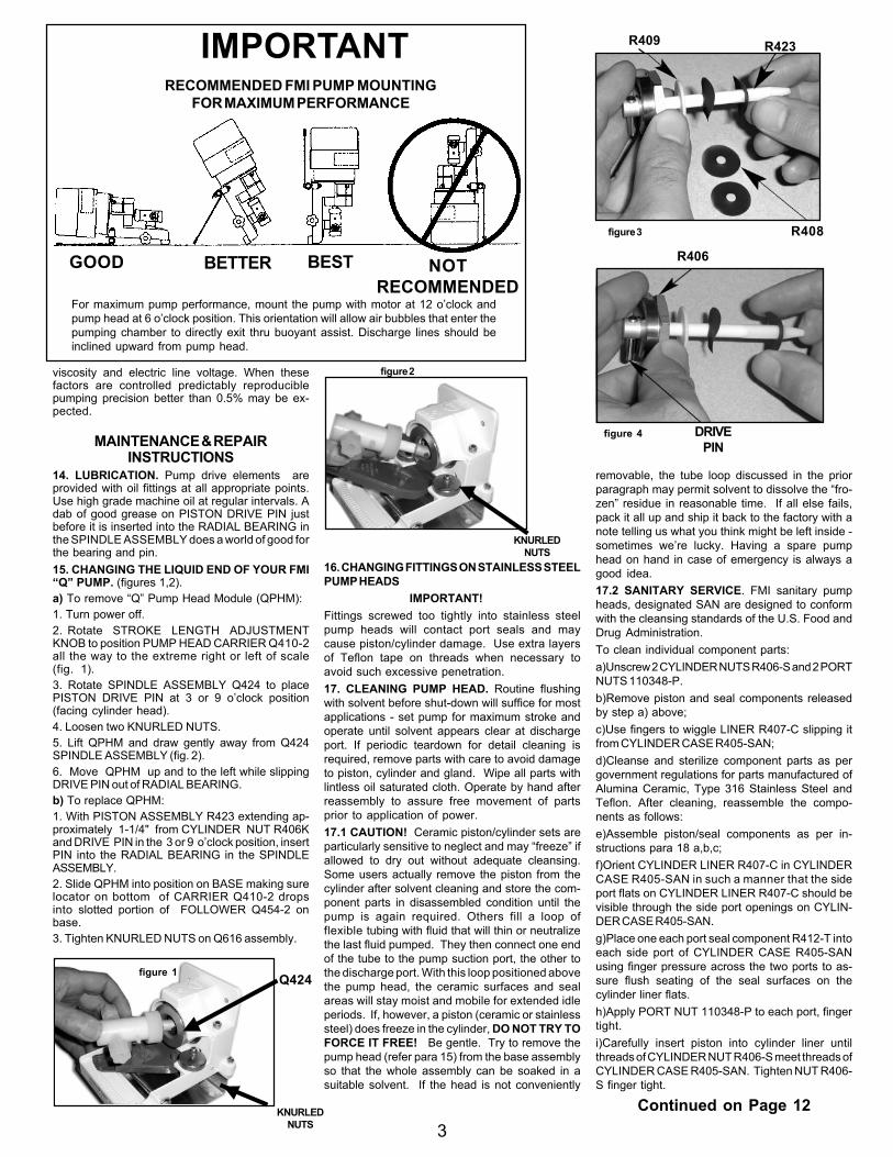
figure 4
IMPORTANT
For maximum pump performance, mount the pump with motor at 12 o’clock andpump head at 6 o’clock position. This orientation will allow air bubbles that enter thepumping chamber to directly exit thru buoyant assist. Discharge lines should beinclined upward from pump head.
GOOD BETTER BEST NOTRECOMMENDED
RECOMMENDED FMI PUMP MOUNTINGFOR MAXIMUM PERFORMANCE
R406
3
DRIVEPIN
Q424
KNURLEDNUTS
viscosity and electric line voltage. When thesefactors are controlled predictably reproduciblepumping precision better than 0.5% may be ex-pected.
MAINTENANCE & REPAIRINSTRUCTIONS
14. LUBRICATION. Pump drive elements areprovided with oil fittings at all appropriate points.Use high grade machine oil at regular intervals. Adab of good grease on PISTON DRIVE PIN justbefore it is inserted into the RADIAL BEARING inthe SPINDLE ASSEMBLY does a world of good forthe bearing and pin.15. CHANGING THE LIQUID END OF YOUR FMI“Q” PUMP. (figures 1,2).a) To remove “Q” Pump Head Module (QPHM):1. Turn power off.2. Rotate STROKE LENGTH ADJUSTMENTKNOB to position PUMP HEAD CARRIER Q410-2all the way to the extreme right or left of scale(fig. 1).3. Rotate SPINDLE ASSEMBLY Q424 to placePISTON DRIVE PIN at 3 or 9 o’clock position(facing cylinder head).4. Loosen two KNURLED NUTS.5. Lift QPHM and draw gently away from Q424SPINDLE ASSEMBLY (fig. 2).6. Move QPHM up and to the left while slippingDRIVE PIN out of RADIAL BEARING.b) To replace QPHM:1. With PISTON ASSEMBLY R423 extending ap-proximately 1-1/4" from CYLINDER NUT R406Kand DRIVE PIN in the 3 or 9 o’clock position, insertPIN into the RADIAL BEARING in the SPINDLEASSEMBLY.2. Slide QPHM into position on BASE making surelocator on bottom of CARRIER Q410-2 dropsinto slotted portion of FOLLOWER Q454-2 onbase.3. Tighten KNURLED NUTS on Q616 assembly.
16. CHANGING FITTINGS ON STAINLESS STEELPUMP HEADS
IMPORTANT!Fittings screwed too tightly into stainless steelpump heads will contact port seals and maycause piston/cylinder damage. Use extra layersof Teflon tape on threads when necessary toavoid such excessive penetration.17. CLEANING PUMP HEAD. Routine flushingwith solvent before shut-down will suffice for mostapplications - set pump for maximum stroke andoperate until solvent appears clear at dischargeport. If periodic teardown for detail cleaning isrequired, remove parts with care to avoid damageto piston, cylinder and gland. Wipe all parts withlintless oil saturated cloth. Operate by hand afterreassembly to assure free movement of partsprior to application of power.17.1 CAUTION! Ceramic piston/cylinder sets areparticularly sensitive to neglect and may “freeze” ifallowed to dry out without adequate cleansing.Some users actually remove the piston from thecylinder after solvent cleaning and store the com-ponent parts in disassembled condition until thepump is again required. Others fill a loop offlexible tubing with fluid that will thin or neutralizethe last fluid pumped. They then connect one endof the tube to the pump suction port, the other tothe discharge port. With this loop positioned abovethe pump head, the ceramic surfaces and sealareas will stay moist and mobile for extended idleperiods. If, however, a piston (ceramic or stainlesssteel) does freeze in the cylinder, DO NOT TRY TOFORCE IT FREE! Be gentle. Try to remove thepump head (refer para 15) from the base assemblyso that the whole assembly can be soaked in asuitable solvent. If the head is not conveniently
removable, the tube loop discussed in the priorparagraph may permit solvent to dissolve the “fro-zen” residue in reasonable time. If all else fails,pack it all up and ship it back to the factory with anote telling us what you think might be left inside -sometimes we’re lucky. Having a spare pumphead on hand in case of emergency is always agood idea.17.2 SANITARY SERVICE. FMI sanitary pumpheads, designated SAN are designed to conformwith the cleansing standards of the U.S. Food andDrug Administration.To clean individual component parts:a)Unscrew 2 CYLINDER NUTS R406-S and 2 PORTNUTS 110348-P.b)Remove piston and seal components releasedby step a) above;c)Use fingers to wiggle LINER R407-C slipping itfrom CYLINDER CASE R405-SAN;d)Cleanse and sterilize component parts as pergovernment regulations for parts manufactured ofAlumina Ceramic, Type 316 Stainless Steel andTeflon. After cleaning, reassemble the compo-nents as follows:e)Assemble piston/seal components as per in-structions para 18 a,b,c;f)Orient CYLINDER LINER R407-C in CYLINDERCASE R405-SAN in such a manner that the sideport flats on CYLINDER LINER R407-C should bevisible through the side port openings on CYLIN-DER CASE R405-SAN.g)Place one each port seal component R412-T intoeach side port of CYLINDER CASE R405-SANusing finger pressure across the two ports to as-sure flush seating of the seal surfaces on thecylinder liner flats.h)Apply PORT NUT 110348-P to each port, fingertight.i)Carefully insert piston into cylinder liner untilthreads of CYLINDER NUT R406-S meet threads ofCYLINDER CASE R405-SAN. Tighten NUT R406-S finger tight.
Continued on Page 12
R423
figure 2
figure 1
KNURLEDNUTS

4
5 Aerial Way, Suite 500, Syosset, NY 11791(516)922-6050 l FAX (516)624-8261 l www.fmipump.com

5For Additional Information Call - Toll Free 800-223-3388 or email us at: [email protected]
IMPO
RTA
NT!
WH
EN O
RD
ERIN
G R
EPLA
CEM
ENT
PAR
TS P
LEA
SE M
ENTI
ON
MO
DEL
AN
D S
ERIA
L N
UM
BER
S O
F TH
E PU
MP
ON
WH
ICH
THEY
WIL
L B
E U
SED
.
REP
LAC
EMEN
T C
YLIN
DER
CA
SE (R
405-
K) O
NLY
SO
LD W
ITH
CYL
IND
ER L
INER
CER
AM
IC P
ISTO
NS
& C
YLIN
DER
LIN
ERS
SOLD
AS
SETS
ON
LY
PLEA
SE N
OTE
: FM
I PR
OVI
DES
A 4
8 H
OU
R T
UR
N A
RO
UN
DR
EPA
IR S
ERVI
CE
(SEE
PA
GE
7 FO
R D
ETA
ILS)


7
PART NO. DESCRIPTION
Q410-2 CARRIERQ410-3 CARRIER STAINLESS STEELQ665 SPACER
R405-K CYL CASE, FLUOROCARBON, DBL CAPR405-1K CYL CASE, FLUOROCARBON, STANDARDR405-S CYL CASE, STAINLESS STEELR405-1S CYL CASE, SS, TEMP GLANDR405-SAN CYL CASE, SANITARY STAINLESS STEELR405-SG CYL CASE, SS ISOLATION GLANDR406-K GLAND NUT, FLUOROCARBONR406-0K GLAND NUT, FLUOROCARBON 1/8” PISTONR406-1K GLAND NUT, FLUOROCARBON 1/4” PISTONR406-2K GLAND NUT, FLUOROCARBON 3/8” PISTONR406-3K GLAND NUT FLUOROCARBONR406-S CYLINDER NUT R405-S, R405-SANR407-0 CYLINDER LINERR407-1 CYLINDER LINERR407-2 CYLINDER LINERR407-1C* CYLINDER LINERR407-2C* CYLINDER LINERR407-3C* CYLINDER LINERR408-1A LIP SEAL, RULON AR 1/4”R408-2A LIP SEAL, RULON AR 3/8”R408-0J LIP SEAL, RULON J 1/8”R408-1J LIP SEAL, RULON J 1/4”R408-2J LIP SEAL, RULON J 3/8”R408-1T LIP SEAL, TEFLON 1/4”R408-2T LIP SEAL, TEFLON 3/8”R408-3A LIP SEAL, RULON AR 1/2”R408-3T LIP SEAL, TEFLON 1/2”R409-0 GLAND WASHER, TEFLON 1/8”R409-1 GLAND WASHER, TEFLON 1/4”R409-2 GLAND WASHER, TEFLON 3/8”R409-3 GLAND WASHER TEFLON 1/2”
PART NO. DESCRIPTION
R412-1 ADAPTER, S.S. 1/4 NPT TO 1/4” I.D. TUBER412-2 ADAPTER, S.S. 1/4 NPT TO 3/8” I.D. TUBER412-0K ADAPTER, FLUOROCARBON 1/8” I.D. TUBER412-1K ADAPTER, FLUOROCARBON 1/4” I.D. TUBER412-2K ADAPTER, FLUOROCARBON 3/8” I.D. TUBER412-5K ADAPTER, FLUOROCARBON 1/4-28 THDR412-6K ADAPTER, FLUOROCARBON 1/2” I.D. TUBER412-07 ADAPTER, S.S. 1/4” I.D. TUBE, SANR412-08 ADAPTER, S.S. 3/8” I.D. TUBE, SANR412-1T ADAPTER, TEFLON 1/4” I.D. TUBE, SANR412-2T ADAPTER, TEFLON 3/8” I.D. TUBE, SANR413 CYLINDER HEAD SEALR413-1 CYLINDER HEAD SEAL, R405-1KR419 CYLINDER PORT SEAL, R405-SR423-1C* PISTONR423-2C* PISTONR423-3C* PISTONR423-0S PISTONR423-1S PISTONR423-2S PISTONR479 LOW FLOW KIT (FITS R405-S)R489 SPACER, SANITARY CYLINDER GROUPR490-1 PORT SLEEVE, SANITARY CYLINDER GROUPR520-1T ADAPTER, TEFLON 1/4” O.D. STRAIGHT, SANR520-2T ADAPTER, TEFLON 3/8” O.D. STRAIGHT, SAN
H476-K SML TUBE ADAPTER SET, 1/8” O.D. (OPTL)
110017-10 SCREW, SKT HD CAP 1/4-20 X 5/8”110311 NUT, SQUARE 1/4-20110348-P SAN PORT NUT, PLASTIC110348-S SAN PORT NUT, STAINLESS STEEL110384-K FERRULE NUT 1/4, KYNAR110384-T FERRULE NUT 1/4”, TFE110847-01 BARBED FITTING 10-32 UNC-2B 1/8” ID TUBING200182-01 CYL CASE, SS HIGH TEMP GLAND500074 LIP SEAL INSTALLATION TOOL,1/8”500071 LIP SEAL INSTALLATION TOOL,1/4”500080 LIP SEAL INSTALLATION TOOL,3/8”500081 LIP SEAL INSTALLATION TOOL,1/2”
Q PUMP HEAD MODULE - PARTS PRICE LIST
* CERAMIC PISTONS & CYLINDER LINERS SOLD AS SETS ONLY
For Additional Information Call - Toll Free 800-223-3388 or email us at: [email protected]
PUMP HEAD REPAIR SERVICEShould your FMI PUMP or PUMP SUBASSEMBLY need repairs, you should first contact the CustomerService Department for a SERVICE SAFETY ASSURANCE FORM and a RETURN AUTHORIZATIONNUMBER, you may then ship it to us post-paid. You will be charged a flat $38.00 service fee for each PumpHead Module returned plus the cost of parts used and the postage required to return it to you. The PumpHead Module service fee includes inspection, clean and test to agreed specifications and the replacementof Lip Seals and Gland Washer.If after examining a returned pump or subassembly, the FMI Service Department estimates the total costto be in excess of $60.00, you will be requested to approve the charges before repair work is started.
PARTS ORDERSMINIMUM ORDER $25.00 DOMESTIC or FOREIGN (Invoice price exclusive of shipping)
SHIPPINGParts and repair orders will be shipped via United Parcel Service or U.S. Postal Service unless other meansare specified.
ALL PRICES ARE QUOTED IN U.S. DOLLARS, FOB SYOSSET, NY - Subject to change without notice.
call for
Pricing!
call for
Pricing!

8
FMI MODEL Q PUMPSPARTS IDENTIFICATION SHEET Q431-05

9
FMI MODEL Q PUMPSPARTS IDENTIFICATION SHEET Q431-05
FOR ADDITIONAL INFORMATIONCALL TOLL FREE 800-223-3388 or516-922-6050 l FAX 516-624-8261
email: [email protected]
PLEASE NOTE FMI PROVIDES A 48HOUR TURN AROUND REPAIR SER-VICE (see page 11 for details)
IMPORTANT!
WHEN ORDERING REPLACEMENTPARTS, PLEASE MENTION MODEL &SERIAL NUMBERS OF PUMP ONWHICH THEY WILL BE USED.

10
nections are correct. Upon removal of V200 cover,use a non-metallic screwdriver to avoid shorting ofthe control circuit. After adjustment and beforereplacing the cover, be sure no foreign materialsare on the circuit board.
A) Minimum Speed Adjustment- The MIN.SPD adjustment sets the speed that the motor willattain when the Digital Potentiometer is set to 0%of flow which is the factory preset. To adjustminimum speed, set the Digital Potentiometer to0% flow (00.0) and advance the MIN. SPD adjust-ment until the desired speed is achieved. Therange is 0% to approximately 50% of the controlrated output voltage (90 VDC). This adjustmentshould be made before setting the MAX. SPDadjustment. There is some interaction betweensettings.
B) Maximum Speed Adjustment - This setsthe speed that the motor will attain when the DigitalPotentiometer is set to 99.9% flow (99.9). Maxi-mum speed is set at the factory to 1800 spm. Thesetting of the MAX. SPD adjustment has no effectwhen operating in the SIGNAL mode. To set adifferent maximum speed, turn the Digital Potenti-ometer to 99.9% of flow and adjust the MAX. SPDadjustment. The maximum speed may be set aslow as 50% of the control rated output voltage (90VDC).
V200-02
INSTALLATION & OPERATING TIPS
MODELS QV, Q2V, QVG50, AND RHV
1. CONTROL FUNCTION: The FMI stroke ratecontroller, V200 used with Models QV, Q2V, QVG50,and RHV pumps has four switches to control itsfunctions: a) A two position power on-off switch. b)A two position direction switch. c) A Digital Poten-tiometer for control of percent of flow. A setting of99.9 yields approximately 100% of maximum flow.d) A two position control method switch. In the upor manual position it allows for direct control ofpercent of flow by setting the Digital Potentiometer.In the down or 4-20 mA position, control is switchedto the 4-20 mA terminal strip inputs and the DigitalPotentiometer is disabled. Stroke rate is thencontrolled via a customer supplied DC currentsource with an input impedance of approximately500 Ohms.
2. FUSING: The motor and its control are protectedagainst overloads by a current limit circuit andadditional protection is provided by a .75 amp fuseon input line (hot side). Replacement fuses must be.75 amp Slo Blow.
3. TRIM POT ADJUSTMENTS: The V200 trim potsare factory set and should not be adjusted. 0 =minimum and 1800 = maximum strokes per minute.If other than standard settings are desired pleasenote Trim Pot Adjustment Methods.
4. TRIM POT ADJUSTMENT METHODS: Beforeadjusting control unit, carefully check that all con-
V200 STROKE RATECONTROLLER
0
400
800
1200
1600
2000
2400
0.0 10.0 20.0 30.0 40.0 50.0 60.0 70.0 80.0 90.0 99.9
FORWARD REVERSE
PERCENT OF FLOW
V200 MOTOR CONTROLLER - MANUAL CONTROL
0
400
800
1200
1600
2000
2400
4 4.5 5 6 7 8 9 10 11 12 13 14 15 16 17 18 19 19.5 20
FORWARD REVERSE
AMPERAGE (mA)
V200 MOTOR CONTROLLER - MILLIAMP CONTROL
INPUT SIGNAL RESPONSE CURVESMANUAL CONTROL RESPONSE CURVES
INSTRUCTIONS
C) Input Signal Scaling- Two adjustmentsmay be made to calibrate the V200 to follow itssignal source. First, apply the 20 mA signal into thecontrol and adjust the SIG ADJ. trimpot to bring themotor to 1800 spm. Then apply a 4 mA signal to thecontrol and adjust the LINEARITY trim pot to bringthe motor to the speed desired at that low signal. InSIGNAL mode, verify that the input signal is at 4 mA.In MANUAL mode, verify that the Digital Potentiom-eter is set to 0% of flow (00.0). Slowly increase thesignal input, or slowly increase the percent of flowsetting. The motor must start slowly and increase itsspeed in approximate proportion to the increasingspeed setting. If the motor rotates opposite to theintended direction, shut down the control and re-verse the connections made to terminals A1 and A2,located on the edge of the circuit board nearest thedigital potentiometer. Restore power to the control.
D) IR Comp Adjustment- This controls thedegree to which the V200 compensates for changesin motor load to maintain essentially constant motorspeed over the load range. It is factory set with therated horsepower motor.
5. POWER REQUIREMENTS: The V200 stroke ratecontroller requires a 115 VAC, 50/60 Hz power source inorder to function. For usage at 230 VAC @ 50 Hz FMIrecommends the use of a step-down transformer ratedat 150 VA minimum.
5 Aerial Way, Suite 500, Syosset, NY 11791(516)922-6050 l FAX (516)624-8261 l www.fmipump.com

11For Additional Information Call - Toll Free 800-223-3388 or email us at: [email protected]
PART NO. DESCRIPTION
Q421-1 BASE ASS’Y QPQ421-3 BASE ASS’Y QB, QD,QV, QBGQ421-4 BASE ASS’Y QSYQ421-5 BASE ASS’Y QSYXQ421-6 BASE ASS’Y QG, QVG50Q421-7 BASE ASS’Y QDXQ424 SPINDLE ASSEMBLY QP, QDXQ447 BUSHING, FLOW CONTROLQ454-3 FOLLOWERQ464 STROKE LENGTH ADJUSTMENT KNOBQ485 DIAL INDICATOR KITQ616 RETAINER ASSEMBLYQ647 BASE MOUNTING KITQ662 TILT STAND KIT
R424-1 SPINDLE ASSEMBLY QD, QG, QB, QV, QVGR424-6 SPINDLE ASSEMBLY QSY, QSYXR475 FOOT QSYX
P56C FACE MOTOR ADAPTER KITV109 MOTOR ASSEMBLY QVV109G MOTOR ASSEMBLY QVG50
110049 WASHER #8 INT. LOCK110258 FOOT, RUBBER110262 MOTOR, QD PUMP 115V, 60Hz110262-2 MOTOR, QD PUMP 230V , 50/60 Hz110286-6A MOTOR, QG 6 RPM 115V, 60Hz110286-20A MOTOR, QG 20 RPM 115V, 60 Hz110286-50A MOTOR, QG 50 RPM 115V, 60 Hz110286-150A MOTOR, QG 150 RPM 115V, 60 Hz110286-400A MOTOR, QG 400 RPM 115V, 60 Hz110290-8 SCREW, SKT HD 8-32 X 1/2”
PART NO. DESCRIPTION
110290-10 SCREW, SKT HD #8-32 X 5/8”110290-22 SCREW, #8-32 X 1 3/8”110297-6 DRIVE SCREW , 8-32 X 3/8”110306-1 MOTOR, QSY 115V, 60Hz110306-2 MOTOR, QSY 230V, 50/60Hz110314 WASHER, #10 INT. LOCK110336-2 MOTOR 230 VAC 50/60Hz QSYX110337-2 RESISTOR (110336-2 230V, 50/60Hz)110338-2 CAPACITOR (110336-2 230V, 50/60Hz)110355-1 MOTOR, 12 VDC QB110373 DRIVE COUPLING110376-16 BOLT, HEX HD 3/8 -16 X 1”110417-4 STANDOFF, HEX 8-32 X 1/4Ó FEM.110454 CAP NUT 8-32110471 LOCK NUT 1/4-20110491 WASHER, FLAT 1/4” STD110505 WASHER, SHOULDER, NYLON110506-8 SCREW, SKT HD CAP 10-32 X 1/2”110509 ADAPTER, PC56C110522 MOTOR, X-PROOF QDX 115/230 VAC 60 HZ110542-6 SCREW, HEX HD NYLON 8-32 X 3/8”110544 SPEED KNOB110579 WASHER, FLAT 3/8”110580 WASHER, LOCK INT. 3/8”110608 SPRING AND BRUSH SET, QVG50110609 BRUSH CAP , QVG50110671-4 SCREW, SET 8-32 X 1/4”110837-01 SPRING BRUSH SET 12 VDC - GRAY MOTOR110838-01 SPRING BRUSH SET 90 VDC - GRAY MOTOR110839-01 BRUSH CAP 12, 90 VDC - GRAY MOTOR110877 SPACER
PUMP DRIVE REPAIR SERVICEShould your FMI PUMP DRIVE or SUBASSEMBLY need repairs, you should first contact the CustomerService Department for a RETURN AUTHORIZATION NUMBER; you may then ship it to us post-paid.You will be charged a flat $38.00 service fee for each Pump Drive Module or subassembly returned plus thecost of parts used and the postage required to return it to you.If after examining a returned pump or subassembly, the FMI Service Department estimates the total cost tobe in excess of $60.00, you will be requested to approve the charges before repair work is started.
PARTS ORDERSMINIMUM ORDER $25.00 DOMESTIC or FOREIGN (Invoice price exclusive of shipping)
SHIPPINGParts and repair orders will be shipped via United Parcel Service or U.S. Postal Service unless other meansare specified.
Q PUMP DRIVE MODULE - PARTS PRICE LIST
ALL PRICES ARE QUOTED IN U.S. DOLLARS, FOB SYOSSET, NY - Subject to change without notice.
call for
Pricing!

IMPORTANT
WHEN ORDERING REPLACEMENT PARTS PLEASE MENTION MODEL AND SERIAL NUMBERSOF THE PUMP ON WHICH THEY WILL BE USED.
Record your Model and Serial Numbers below. This will be useful when ordering replacement parts.PUMP HEAD MODULES (PHM) PUMP DRIVE MODULE (PDM)
PHM MODEL NUMBER PHM SERIAL NUMBER PDM MODEL NUMBER PDM SERIAL NUMBER_____________________ QB__________________ _____________________ QA_______________________________________ _____________________ _____________________ _________________________________________ _____________________ _____________________ _________________________________________ _____________________ _____________________ ____________________
PLEASE NOTE:
Pistons and cylinders should be dimensionally mated at the factory. For most satisfactory performance, they shouldbe ordered as mated sets.
IN-Q431-05 INSTRUCTIONS
12
j) Place head seal components R413 and R489 intothe head end of CYLINDER CASE R405-SAN,apply CYLINDER NUT R406-S.k) Wrench tighten each PORT NUT 110348-P 1/6turn.l) Wrench tighten each CYLINDER NUT R406-S1/2 turn, piston end first.18. PISTON SEAL REPLACEMENT (please seepara 5.) When R408 SEALS are replaced, thefollowing procedure should be followed: (pleasesee figs. 3,4)a) Place GLAND NUT R406 and GLAND WASHERR409 on PISTON ASSEMBLY R423.b) Place the lip seal installation tool over the endof the piston. Slide the tool until piston is seatedin tool. (See lip seal insertion tool table bellow).c) First “Form” lip of lip seal by gently a placing a
lip seal R408 on tool, lip side last. Carefully rotatethe seal on the tool while sliding the seal over thetool’s neck to avoid damage to the lip. Then removeseal and reverse lip direction (FIG.3)d) Gently place one “formed” LIP SEAL R408 onpiston, lip side first, carefully rotating the sealon the tool until it is past the tool and on the pistone) Gently place one LIP SEAL R408 on piston, lipside last. Carefully rotate the seal on the tool toavoid damage to the lip while passing over the toolto the piston (fig. 4).f) Remove installation tool from the piston.g) Insert piston into cylinder approximately oneinch.h) Apply GLAND NUT R406 to cylinder threads,seat gland nut, then tighten to 1/3 turn maximum.
lip seals (part R408) in pump head it is recom-mended that the seals be set (formed in place) byfluid pressures generated by pump action. Toaccomplish this:a) Operate the pump spindle clockwise for 10 or20 strokes at maximum setting, handling water(left to right mode facing pump head) withsuction line blocked or pinched off. This willcreate a vacuum in the pump head, permittingatmospheric pressure to shape the outer sealmember tightly around the piston.b) Reverse the pumping direction (pump head anglereversal) and intermittently block the line leadingfrom the left hand port. This will generate pressurein the seal area of the pump head, causing the innerseals to form intimately around the piston.
19. PISTON SEAL SETTING. After installing new
Lip Seal Insertion Tools, Q431-05
Piston Size Code
Piston Diameter (inches)
Tool Part Number
Q0 1 / 8 500074 Q1 1 / 4 500071 Q2 3 / 8 500080 Q3 1 / 2 500081