Embed Size (px)
Citation preview
Calhoun: The NPS Institutional Archive
Faculty and Researcher Publications Faculty and Researcher Publications Collection
2003-01
Performance characterization of a valveless pulse
detonation engine
Brophy, C.M.
AIAA
AIAA 2003-1344, 41st Aerospace Sciences Meeting and Exhibit, 6-9 January 2003, Reno
Nevada, pp. 1-11
http://hdl.handle.net/10945/47722
AIAA 2003-1344
Performance Characterization of a Valveless Pulse Detonation Engine
C.M. Brophy’, LT S. Wernert, and J.O. Sinibaldil Department of Aeronautics and Astronautics
Naval Postgraduate School Monterey, CA
Abstract
A valveless pulse detonation engine geometry has been partially evaluated on a direct-connect test stand at simulated inlet flight conditions to the combustor. The geometry utilizes a fuel/oxygen- enriched air initiator to initiate detonations in the main combustor and has been operated on ethylene, propane, and JP-IO. The initiator has been operated at frequencies up to 100 Hz. The main combustor of the engine has only been evaluated up to 30 Hz operation due to a current design constraint which will be modified to allow higher frequencies in subsequent tests. The use of an initiator required the evaluation of the diffraction limits between the initiator exit and the main combustor. The successful use of an initiator to detonate a fueVair mixture in a larger main combustor has been demonstrated. Furthermore, experimental data corroborated that tailoring the initiator to produce an overdriven detonation condition at its exit plane, enhanced the detonation transition into the larger combustor. Using imaging optical diagnostics, Mach reflections were observed at the combustor’s wall just a few centimeters downstream of the initiator’s plane. These appear to be the primary re-initiation mechanism for the re-establishment of fuel-air detonations for this geometry. Results show that a diameter ratio between the combustor and the initiator of at least 1.5:l will allow successful operation for ethylene and propane. Single-shot diffraction tests evaluated combustor to initiator diameter ratios up to 1.58.
The specific impulse was computed from experimental measurements using both ethylene and propane fuels at various equivalent ratios from 1 .O to 1.5. The results showed Isp values rangins from 850 to almost 1200 seconds, but these relative low values were anticipated due to the
oversize initiator used in this study. Such a large initiator was required in order to characterize the aforementioned diameter ratios. Future tests will incorporate an optimally sized initiator, and extrapolation of the current data indicates possible Isp values as high as 1800 seconds with a stoichiometric propane - air mixture. This would indicate similar performance values to more conventionally valved PDE systems.
Introduction
The interest in pulsed detonation engines (PDEs) has increased dramatically in recent years due to their high theoretical performance and wide range of potential applications’. Practical operation of these systems requires the use of fuels that have already gained acceptance/approval by the military and/or aviation industry, such as kerosene based Jet-A, JP-5, or JP-10. The use of such fuels has inherent difficulties since such fuel- air mixtures are often difficult to detonate2, 3,
especially in a repetitive and reliable manner. Therefore various research teams are currently investigating the use of an initiator, which consists of a small tube or auxiliary combustor filled with mixtures highly sensitive to detonation as the means to initiate a detonation in a larger main combustor containing a less sensitive fuel-air mixture. Thus the importance of detonation diffraction or transmission from the small tube into a larger main combustor tube often arises.
Various initiator concepts exist and can vary from coaxial designs to transverse or splitter plate concepts just to name a few. Most concepts operate on fuel-oxygen mixtures while others utilize a blend of oxygen-enriched air as the oxidizer. Although the use of oxygen provides
_ _ _ _ _ _ _ _ _ _ ~
*Research Assistant Professor, AIAA Member. +Student, AIAA Student Member. This material is a work of the U.S. Government and is not subject to copyright protection in the United States.
1 American Institute of Aeronautics and Astronautics
41st Aerospace Sciences Meeting and Exhibit6-9 January 2003, Reno, Nevada
AIAA 2003-1344
This material is declared a work of the U.S. Government and is not subject to copyright protection in the United States.
Dow
nloa
ded
by N
AV
AL
PO
STG
RA
DU
AT
E S
CH
OO
L o
n M
arch
28,
201
4 | h
ttp://
arc.
aiaa
.org
| D
OI:
10.
2514
/6.2
003-
1344
AIAA 2003-1344
excellent reliability, repeatability, and a vary rapid ignition event, the minimization of the oxygen required is of paramount performance since it is treated as "fuel" for specific impulse (Isp) and specific fuel consumption (SFC) calculations and directly reduces the overall system performance. Thus, efficient coupling between an initiator and the larger combustor is of high importance.
The pulse detonation engine geometry under development at the Naval Postgraduate School utilizes a continuous air flow design, which does not require valves for the air supply to the combustion chamber. The geometry utilizes the initiator approach described earlier and is depicted in Figure 1 . The initiator combustor operates on an oxygen-enriched fuel-air mixture to rapidly and reliably generate a detonation wave which can then be used to initiate the less sensitive fuel-air mixture located in the main combustor. The absence of a large valve on the air flow has permitted a convenient flow path to rapidly fill, detonate, and purge the combustion chamber at rates up to 100 Hz, but has also introduced difficulties into the initiation process due to lowered confinement conditions when compared to conventional PDE concepts which involve some type of valve on the air supply. A critical region of interest is at the initiator exit plane where the exiting detonation wave diffracts into the main combustor. The concern for this area of the system is the motivation for characterizing the effects of the diffraction condition between an initiator of diameter, D,, and the main combustor of diameter, D, at the diffraction plane. The effects of diameter ratio (D/D,), mixture variation (overdrive), and varying degrees of confinement are being evaluated so that a more optimized condition can exist.
A large body of historical work has investigated the classical case of detonation transmission from a confined tube to an unconfined volume4 for homogeneous mixtures. The well documented critical diameter value of 13 times the cell size (h) of the mixture for transmission of a detonation wave to an unconfined volume has been verified many times to hold true for most mixtures. The 13h value has been shown to be specifically valid for mixtures cmtaining morc i r rqu ln r tell <p,ncinF. typicdly fueVair mixtures with higher activation energies. Mixtures containing highly regular detonation cell
structure, such as argon diluted fuel/oxygen mixtures have been shown to often require a larger critical diameter than the 13h rule, thus revealing the increased importance of wavefront structure during the diffraction processes in producing gas- dynamic hot spots for spontaneous reignition to occur. The increased irregularity in the cellular structure for fuel-air mixtures often aids in the adjustment to sudden expansion conditions and can be interpreted as possessing more levels of instability and therefore more modes by which spontaneous reinitiation may occur near a critical diameter value5.
Teodorcyzk6 and Oran'** have looked at the reinitiation mechanisms of Mach reflections at a rigid wall from the propagation of a quasi- detonation in a obstacle-laden channel and an imparting spherical blast wave on a rigid wall, respectively. Both studies stressed the importance of the rapid reignition sites immediately behind the generated Mach stems at the wall. Murray' also demonstrated the importance of shock-shock and shock-wall collisions for different exit conditions at the diffraction plane, including tube bundles, annular orifices, and cylindrical diffraction. The reinitiation mechanism associated with the Mach reflections observed in those studies is extremely important for initiator concept utilized in the current engine. It also becomes increasingly important as the combustor diameter approaches the cell size of the mixture and few transverse waves exist to assist with adjusting to the expansion condition occurring at the diffraction plane. The reinitiation process for such conditions appears to be a very local process and the influence of the wave front structure" and reflection cannot be ignored during analysis.
Desbordes" and Lannoy" have investigated the effects of overdriving a detonation wave during diffraction from a smaller combustion tube to a larger volume. In both studies it was determined that a definitive benefit exists when a detonation wave is allowed to propagate into a less reactive mixture immediately before diffraction occurs, thus creating an overdriven condition in the less reactive mixture. Recently, Murray et aI.l3 investigated the direct benefit of utilizing a fuel- oxygen driver section, an initiator, and prqwgsting the generatted detonation wave into a fuel-air mixture in order to generate the overdriven condition. Overall values of the effectiveness of
2 American Institute of Aeronautics and Astronautics
Dow
nloa
ded
by N
AV
AL
PO
STG
RA
DU
AT
E S
CH
OO
L o
n M
arch
28,
201
4 | h
ttp://
arc.
aiaa
.org
| D
OI:
10.
2514
/6.2
003-
1344
AIAA 2003-1344
driver-receptor mixtures and diameter ratios approached 30 for some conditions indicating that a dramatic reduction in the required critical diameter for the receptor mixture. Thus, a combination of Mach reflections and overdriven conditions are the mechanisms which appear to dominate initiator transmissions on the scale of most PDEs and will likely be responsible for the successful application in such systems.
The operational cycle of the valveless PDE is shown below in Figure 2. The cycle begins with air flowing through the engine and purging the previous combustion products (A). Fuel is injected into the incoming air and flows into the main combustor (B). Near the end of the fuel injection event (C), a highly detonable mixture is rapidly injected into the initiator (D). The mixture in the initiator is ignited and a detonation wave forms (E). The detonation wave exits the initiator and initiates the fuellair mixture residing in the main combustor (G). After the detonation exits the main combustor, a series of rarefaction waves reduce the pressure inside of the combustor and the combustion products are purged (H). The process is then repeated.
Immediately after the detonation wave from the initiator diffracts into the main combustor, a combustion-driven shock wave, which transitions into a decaying blast wave, begins to propagate upstream into the incoming air stream. This propagation can be eliminated if the total pressure of the incoming air is sufficiently high and results in a choke point somewhere in the isolator, thereby producing a supersonic flow regime immediately downstream of this point. The current test program only evaluated subsonic flow conditions and limited the isolator flow Mach number to 0.9. Future testing will explore the supersonic isolator mode.
ExDerimental Setup
The multi-cycle PDE consisted of four fuel-air inlet arms discharging into a common inlet manifold. Vitiated air, up to 550 K, was distributed into the four arms were fuel was then injected using either high-speed solenoid valves or liquid fuel injectors from Sturman Industries. The fuellair mixture was then allowed to co-flow around the initiator, through a 5 degree transition ramp, and then into the main combustor which
was 1 meter in length and had a diameter of 0.1016 meters. The initiator could be moved to different axial positions along the 5 degree transition ramp to determine where the expansion area becomes too large for a detonation wave to transition to the main combustor.
The initiator was a 320.6 mm long stainless steel chamber with a exiting internal diameter of 44.45 mm and used an ethylene/air/oxygen- enriched mixture to rapidly and reliably form a detonation. The overall lengthlvolume was larger than necessary due to the requirement that the initiator exit plane needed to be positioned at various axial locations. The initiator geometry has been previously developed and has demonstrated operation on ethylene, propane, and JPlO.I4 The volume of the initiator was 0.000475 m3 and the volume of main combustor was 0.008533 m3, resulting in a total engine volume of 0.00858 m3.
Diagnostics High frequency Kistler 603B 1 pressure
transducers and type-K thermocouples were placed along the PDE to monitor detonatiodshock wave speeds and engine inlet conditions. Transmission measurements were made at two locations with a 3.39 pm He-Ne laser and an infrared diode to determine the proper timing of the fuel delivery and the resulting fuel mass fraction. The transmission ratio received from the diode was used in conjunction with the Beer- Lambert law, Equation 1, to determine the partial pressure and eventually the mass fraction of the fuel in the mixture at that time of transmission.
Where T is the transmission ratio obtained from the attenuation measurements, x is the transmission path across where the attenuation occurred and a is the abso tion coefficient provided in various references' * I 9 for various fuels. Given this information, the partial pressure p can be calculated and subsequently used to determine temporal fueVair ratios in the main combustor as well as the spatial distribution of fuel along the combustor. Ideally the end of the fuel injection charge would be located precisely at the initiator diffraction plane at the moment the initiator detonation wave diffracts into the main combustor.
T
3 American Institute of Aeronautics and Astronautics
Dow
nloa
ded
by N
AV
AL
PO
STG
RA
DU
AT
E S
CH
OO
L o
n M
arch
28,
201
4 | h
ttp://
arc.
aiaa
.org
| D
OI:
10.
2514
/6.2
003-
1344
AIAA 2003-1344
Detonation wave diffraction conditions at the initiatodmain combustor interface were also characterized on a single-shot detonation facility using high-speed Schlieren and CH* chemi- luminescence imaging which utilized a lOnm FWHM interference filter centered at 43Onm.I’
Thrust measurements were made for the multi-cycle tests by utilizing a spring/damper deflection system and a linear displacement indicator. An average displacement value during the tests was then correlated to an average thrust.
Single-Shot Tests The initial testing for the valveless geometry
began approximately one year ago on a single-shot detonation facility which allowed optical access to the diffraction plane. The 2” x 2” optical port allowed high speed shadowgraph measurements to be made in conjunction with single-image CH* chemiluminescence images. The geometry was representative of the valveless configuration and allowed multiple diffraction ratios to be characterized. The experimental setup for those tests and sample CH* images are shown below in Figure 3.
All tests were performed at a nominal pressure and temperature of lOOkPa and 283 K, respectively. The primary re-initiation mechanism after diffraction was observed to be due to the strong Mach reflections resulting from the residual shock of the decaying blast wave reflecting from the outer wall. The increased heating and d5;sociatcd chcmical activity behind the Mach stem provides the rapid energy release required for re- initiation. It is believed that if the exiting detonation wave from the initiator can be tailored to produce an overdriven detonation, the transmission across the diffraction will be substantially enhanced. A schematic of what is believed to occur is shown in Figure 4 and appears to agree with computational results from Oran and Kailsanath7*I7. Caption (c) in Figure 3 shows the CH* emission commonly found to correspond with the near wall Mach stem reflection and the resulting increase in local reaction rate. This behavior was normally observed at distances less than 1.0 D, from the diffraction plane. Figure 5 summarizes the successful and unsuccessful test conditions for which detonation transmission
occurred for the ethylene-air mixtures for tPic single-shot cases. The results indicate that for an initiator operating equivalence ratio of 1 .O, a diffraction ratio of 1.8 should result in a successful detonation transition to the main combustor.
Multi-Cycle Tests The first series of tests on the multi-cycle
engine were performed to verify fuel delivery and equivalence ratios. The 3.39 micron transmission measurement was used at both the initiator diffraction plane and at the combustor exit to determine fuel arrival and fuel mass fraction. The tests verified successful operation of the liquid and gaseous fuel injectors. Transmission results for 80 Hz operation on liquid propane are shown in Figure 6. The square TTL trace represents the injection command for the initiator and the equivalence ratio trace is that for the propane/air mixture as it entered the main combustor. The variation in equivalence ratio could be minimized by tailored injection of each fuel injector, but tended to become more non-uniform temporally as the operational frequencies increased. Gaseous injection of ethylene and propane tended to be much more consistent resulting in more uniform fuel mass fraction along the combustor.
Two important gas dynamic processes occurring within this engine are the dynamic fill response and the forward/aft propagation of disturbances. Characteristics for the baseline case of D/Di=1.25 is presented in Figures 7 and 8. Figure 7 shows the local Mach number versus area for a mass flow of about 0.30 kg/s. Since the first portion of this test program IYX to cvaluntr thc subsonic isolator operation of this engine, any additional mass flow would force the isolator to choke locally and produce a supersonic flow region immediately downstream of that point. The condition depicted in Figure 7 is for an air mass flow rate of 0.30 kg/s and shows the isolator Mach number approaching 0.95 and then decreasing as the cross-sectional area downstream of the isolator increases. Figure 8 shows the behavior of both the forward propagating and rearward propagating disturbances for a M I S ~ ~ ~ ~ O ~ = O . ~ condition of propane/air at an equivalence ratio of 1.2 and x=O being defined as the initiator exit. The right- running red trace depicts the propagation of the propane/air detonation towards the tube exit at the detonation velocity, VCJ. Immediately behind the
4 American Institute of Aeronautics and Astronautics
Dow
nloa
ded
by N
AV
AL
PO
STG
RA
DU
AT
E S
CH
OO
L o
n M
arch
28,
201
4 | h
ttp://
arc.
aiaa
.org
| D
OI:
10.
2514
/6.2
003-
1344
AIAA 2003- 1344
detonation front are a series of rarefaction waves which gradually reduce the post-detonation pressure to a lower value. Once the detonation wave exits the tube, a series of rarefaction waves bqin to propagate upstream in order to reduce the pressure in the combustor. Only the leading rarefaction wave is depicted in the figure and is shown to propagate at the local speed of sound of the products. This and subsequent expansion waves will eventually catch up to the forward running shock wave, depicted as a left-running blue trace, initially propagating upstream at about VsH=450 m/s in the laboratory reference frame. The propagation of the forward running shock wave eventually ends and the combustor is purged with the incoming air. The process repeats for each detonation cycle. It can be seen that the isolator length for a valveless design operating in a subsonic mode and an isolator Mach number of 0.90 would need to be approximately 0.5 meters long for a 1 meter long main combustor. If the combustor is shorter than this length, the forward propagating disturbance could result in an inlet problem. During this testing, disturbances were prevented from propagating further than 78 cm upstream due to a mass metering venturi.
The engine has been evaluated over a diffraction range of 1.25 to 1.58 and operated on both ethylene and propane fuels from stoichiometric to an equivalence ratio of 1.5. It is expected that the upper limit to be tested will be a diameter ratio of 2.25. It can be seen that ethylene/air mixtures at an equivalence ratio of 1.2 have successful diffracted for all diameter ratios te<ted to date. Propanc has only rexcntly been evaluated, and will continue to be investigated over the up coming months.
Performance Measurements Performance calculations were made for full-
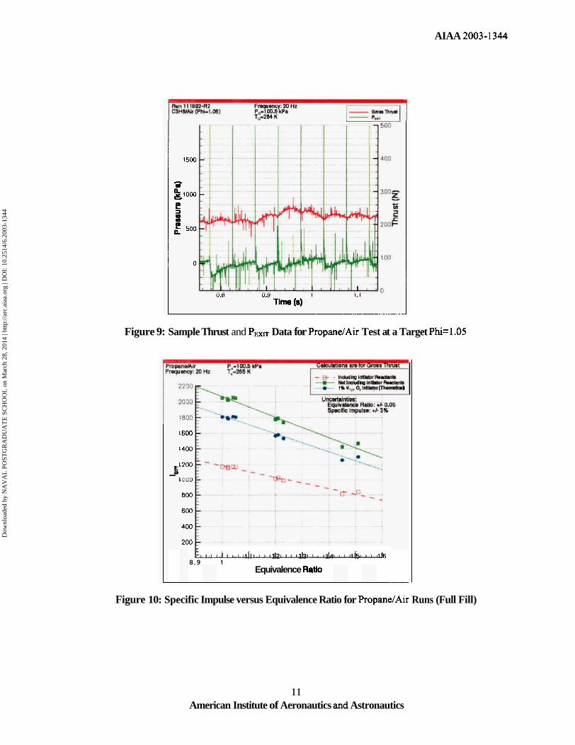
fil l tests which exhibited nearly 100% successful detonations. Although certain runs did involve occasional "misses" or deflagration events, an adequate portion of the run profile was executed to achieve successful quasi-steady state conditions. A sample pressure and thrust dataset for a propanelair run at a target equivalence ratio of 1.05 is shown in Figure 9. The last pressure transducer hefore the comhrqtor exit is shown along with the displacement transducer which recorded the displacement of the engine cradle
which was then correlated to a thrust force. Individual detonation impulses can be seen to "scallop" the force measurements which appear to increase to a quasi-steady state value. The measured thrust on the stand is gross thrust, and therefore includes the thrust contribution due to the purge and fill processes associated with this design.
The specific impulse calculations were made using the gross thrust measurements and net thrust corrections were made by subtracting out the thrust contribution between cycles. The corrections were approximate due to the subjective separation between fill, purge, and blowdown durations. The gross thrust values typically were reduced by 3-4% for the 20 Hz operation at a mass flow rate of 0.32 kg/s. As the operational frequency is increased, the contribution is further reduced. The fuel-based specific impulse was calculated two ways, represented by Equations 2 and 3. First, by only accounting for the fuel in the main combustor and secondly by also accounting for the fuel and extra oxygen used in the initiator.
The results for selected propane/air cases are shown in Figure 10. It can be seen that the spccifir impulse values appear artificially hipher, as expected, when the initiator reactants are ignored. The second calculation, which includes all of the fuel and auxiliary oxygen used in the engine, is obviously the more accurate representation of the total system performance with the relatively large initiator contribution. The theoretical line presented on Figure 10 represents the extrapolated performance if the total auxiliary oxygen requirement for the initiator was reduced to 1% of the total engine volume. Since this would substantially reduce the amount of fuel required for the initiator as well, the increase in specific impulse is dramatic.
If the gross thrust is thrust value obtained, a conventional valved PDE
5
corrected and a net comparison to a system may be
American Institute of Aeronautics and Astronautics
Dow
nloa
ded
by N
AV
AL
PO
STG
RA
DU
AT
E S
CH
OO
L o
n M
arch
28,
201
4 | h
ttp://
arc.
aiaa
.org
| D
OI:
10.
2514
/6.2
003-
1344
AIAA 2003- 1344
attempted. Assuming the aggregate detonation duty cycle is 5% for 20 Hz operation, a 9.69 N value must be subtracted from the gross thrust value to determine the net thrust value. The average net thrust for an equivalence ratio of 1.0 was therefore calculated to be 222.49 N and divided by the 20 Hz frequency for that run resulting in an impulse of 1 1.12 N per detonation event.
This value can be compared to a test case evaluated at Caltech for a stoichiometric propane- air mixture detonated with a propane-oxygen initiator “plug” which was 6% by volume2’. The initial conditions for that test were 100 kPa and 297 K. The impulse per unit volume, I”, was determined to be 1201 kg/m2-s. From this value, the Caltech data would indicate an impulse of 10.31 N, or 7.37% below our calculated net impulse. This is surprising since the Caltech initiator volume was slightly larger than used during these tests. The increased impulse could be caused by additional fuel delivery upstream of the initiator discharge plane due to a solenoid valve staying open longer than expected. In order to eliminate this uncertainty in the future, current, voltage, and pressure monitors will need to be installed on each high speed solenoid valve to determine the actual fuel injection duration for each cycle as well as the location of the heyair mixture interface.
Another contributing factor to the increased net impulse observed is due to the increased amount of working fluid compressed “upstream” involved per detonation event. No attempt was made to account for this effect at this time, but this correction would obviously show the two results in better agreement.
Conclusions and Future Work
The generation of strong Mach stem reflections downstream of the diffraction plane of the initiator combustor were found to be a reliable reinitiation mechanism for the transmission of a detonation wave into a larger combustor over the range of diffraction ratios evaluated to date. So far, diffraction ratios up to 1.58 have been successful with ethylene/air mixtures and pmpnnehir mixtirrer: have heen succcssfid diffracting up to a 1.43 ratio. The reliable generation of Mach stems along the wall
downstream of the diffraction plane for coaxial initiators/combustors should be a valuable mechanism to take advantage during engine design since they do not depend directly on cell size, but on the strength of the exiting shockwave and the physical diffraction condition. The sensitivity of the mixture to reignition can be correlated to the detonation cell size of the reactants used.
The ability to isolate the incoming air flow from the detonation products has been shown to rely heavily on the isolator Mach number and combustion chamber length. Although only subsonic isolator Mach numbers were evaluated during this portion of the test program, sonic or supersonic values corresponding to total pressure of 100 psi or higher will likely provide total inlet isolation from the post detonation pressure and will be evaluated in the next phase of this research.
Specific impulse calculations for the valveless geometry operating on propane/air ranged from 850 to almost 1200 seconds over an equivalence ratio range of 1.5 to 1.0 respectively, but these relative low values were anticipated due to the oversized initiator used in this study. Such a large initiator was required in order to characterize the aforementioned diameter ratios. Future tests will incorporate an optimally sized initiator, and extrapolation of the current data predicts possible Isp values as high as 1800 seconds with a stoichiometric propane - air mixture. This would indicate similar performance values to more conventional valved PDE systems. The minimization ( 4 % by volume) or elimination of auxiliary oxygen for this system will be critical for it to remain competitive with existing propulsion systems. Although it is believed this hurdle can be overcome, it will be difficult. Additionally, the introduction of an exhaust nozzle to the system will introduce further challenges, but may provide an additional performance increase due the thermal-to-kinetic conversion of energy through the nozzle while providing some degree of back pressurization for altitude considerations.
6 American Institute of Aeronautics and Astronautics
Dow
nloa
ded
by N
AV
AL
PO
STG
RA
DU
AT
E S
CH
OO
L o
n M
arch
28,
201
4 | h
ttp://
arc.
aiaa
.org
| D
OI:
10.
2514
/6.2
003-
1344
AIAA 2003- 1344
Nomenclature Oran, E.S., and Boris, J.P., “Ignition in a Complex Mach Structure,” Procrress ifi Astronautics and Aeronautics, Vol. 153,
D Combustor Diameter AIAA, New York, NY, 1993, pp. 241-252. Di Initiator Exit Diameter *Oran, E.S., Jones, D.A., and Sichel, M., g Gravity, 9.81 m/s2 “Numerical Simulations of Detonation mf Mass of Fuel in Main Combustor Transmission,” Proceedings of the Royal mf MIT Mass of Fuel in Initiator
Murray, S.B., Zhang, F., and Gerrard, K.B., “The mo2 - Mass of Extra Oxygen in Initiator P Partial Pressure of Fuel Influence of Driver Power and Receptor T Transimission Ratio Confinement on Pre-Detonators for Pulse TG~OSS Gross Thrust Detonation Engines,” 18” International TmT NetThrust Colloquium on the Dynamics of Explosions X PathLength and Reactive Systems, August 10- 12, 200 1 , VcJ Chapman Jouget Detonation Velocity Seattle, Washington. h Detonation cell size “Edwards, D.H., Thomas, G.O. Thomas, and
Nettleton, M.A., “The Diffraction of a Planar Detonation Wave at an Abrupt Area Change,” Journal of Fluid Mechanics, Vol. 95, pp. 79-
7
Society A , Vol. 436, 1992, pp. 267-297. - 9
References
‘Kailasanath, K., “Recent Developments in the Reseach on Pulse Detonation Engines,” AIAA Paper No. 2002-0470.
2Lee, J.H.S., and Guirao. C.M.. “Fuel-Air Explosions,” Proceediiics d 1 1 1 ~ . Iritcriintionnl Conference 011 I:uaJ-Air L,xulosiorls, November 4-6, 1981, University of Waterloo Press, Waterloo, Ontario, 1982, p. 1005.
3Beeson, H.D. McClenagan, R.D., Pitz, W.J., Westbrook, C.K., and Lee, J.H.S., “Detonabilty of Hydrocarbon Fuels in Air,” Progress in Astronautics and Aeronautics, Vol. 133, AIAA, New York, NY, 1990, pp. 19-36.
Knystautas, R., Lee, J.H., and Guirao, C.M., “The Critical Tube Diameter for Detonation Failure in Hydrocarbon-Air Mixtures,” Combustion and Flame, Vol. 48, pg. 63, 1982.
’Moen, I.O., Donato, M., Knystautas, R., and Lee, J.H., “The Influence of Confinement on the Propagation of Detonations Near the Detonability Limit,” 1 Sth Symposium (International) on Combustion, The Combustion Institute, Pittsburgh, PA, 198 1 1 ,
Teodorcczyk, A., Lee, J.H., and Knystautas, R., “Photographic Study of the Structure and Propagration Mechanisms of Quasidetonations in Rough Tubes,” Promess in Astronautics and Aeronautics, Vol. 133, AIAA, New York, NY,
4
pp. 1615-1622, 1980. 6
1990, pp. 223-240.
_ _ 96, 1979.
“Desbordes, D., “Transmission of Overdriven Plane Detonations: Critical Diameter as a Function of Cell Regularity and Size,” 1’Jugress io Asrrwiaulics arid Al-ronadc‘s, Vol. 114, AIAA, New York, NY, 1990, pp. 170- 185, 1988.
Desbordes, D., and Lannoy, A., “Effects of a Negative Step of Fuel Concentration on Critical Diameter of Diffraction of a Detonation,” Progress in Astronautics and Aeronautics, Vol. 133, AIAA, New York, NY,
Murray, S.B., Thibault, P.A., Zhang, F., Bjerketvedt, D., Sulmistras, A., Thomas, G.O., Jenssen, A., and Moen, I.O., “The Role of Energy Distribution on the Transmission of Detonation,” International Colloquium on Control of Detonation Processes, Moscow, Russia, July 4-7,2000.
Brophy, C.M., Sinibaldi, J.O., and Netzer, D.W., “Detonation Studies of JP-10 Sprays and Initiator Development for Pulse Detonation Engines,” 14th ONR Propulsion Meeting, Chicago, IL, Aug. 2001.
Sinibaldi, J.O., Brophy, C.M., Li, C., and Kailasanath, K., “Investigation of Detonation Wave Diffraction During the Ignition of Pulse Detonation Engines,” Yd Joint Meeting of the US, Sections of the Combustion Institute, Oakland, CAY Mar. 25 - 28,2001.
12
1990, pp. 170-1 86. 13
14
15
7 American Institute of Aeronautics and Astronautics
Dow
nloa
ded
by N
AV
AL
PO
STG
RA
DU
AT
E S
CH
OO
L o
n M
arch
28,
201
4 | h
ttp://
arc.
aiaa
.org
| D
OI:
10.
2514
/6.2
003-
1344
AIAA 2003-1344
Murray, S.B. and Lee, J.H., “On the Transformation of Planar Detonation to Cylindrical Detonation,” Combustion and Flame, Vol. 52, pp. 269, 1983.
Kailasanath, K. and Patnaik, G., “Multilevel computational studies of pulse detonation engines,” ISABE 200 1 - 1 172 Proceedings, Bangalore, India.
Japes, D., Beam, B., “Hydrocarbon Gas Absorbtion by a HeNe Laser Beam at a 3.39- m Wavelength,” Applied Optics, Volume 8,
16
17
18
NO. 8, 1969, 1741-1742.
Wthtsd Ah
”Olson, D., Mallard, W., Gardiner, W., “High Temperature Absorbtion of the 3.39 mm He- Ne Laser Line by Small Hydrocarbons,” Applied Spectroscopy, Volume 32, No. 5, 1978,489-493.
2%intenberger, E., Austin, J.M., Cooper, M. Jackson, S., and Shepherd, J.E., “Impulse of a Pulse Detonation Engine: Single Cycle Model” GALCIT Report FM-00-8, May 2002.
L r
Figure 1: Valveless PDE Configuration
L m F
. . . & =-; - - - - e- Figure 2: Operational Cycle of a Valveless PDE
C
8 American Institute of Aeronautics and Astronautics
Dow
nloa
ded
by N
AV
AL
PO
STG
RA
DU
AT
E S
CH
OO
L o
n M
arch
28,
201
4 | h
ttp://
arc.
aiaa
.org
| D
OI:
10.
2514
/6.2
003-
1344
AIAA 2003-1344
(c) (dl Figure 3: Experimental Setup for Single-Shot CH* Images (left) Sample Images at (a)
t=15 ps (b) t=22 p ,(c) t=29 ps, (d) t=36 ps for a Diameter Ratio of 1.33.
Figure 4: Representation of the Observed Detonation DifitactiodReinitiation Process
Figure 5: Raults for the Two-Dimensional Single-Shot Diffraction Tests
9 American Institute of Aeronautics and Astronautics
Dow
nloa
ded
by N
AV
AL
PO
STG
RA
DU
AT
E S
CH
OO
L o
n M
arch
28,
201
4 | h
ttp://
arc.
aiaa
.org
| D
OI:
10.
2514
/6.2
003-
1344

AIAA 2 0 3 - 1344
Figure 6:
e P
I D 3 t 4 4 I .va tu3 A&) riming and Equivalence Ratio vs. Time for Propane/Air Injection
Figure 7: Local Mach Number and Cross-sectional Area vs. Length along PDE
-llcrp-m
Figure 8: x-t Diagram of Forward and Rearward Propagation of Disturbances
10 American Institute of Aeronautics and Astronautics
Dow
nloa
ded
by N
AV
AL
PO
STG
RA
DU
AT
E S
CH
OO
L o
n M
arch
28,
201
4 | h
ttp://
arc.
aiaa
.org
| D
OI:
10.
2514
/6.2
003-
1344
AIAA 2003-1344
Figure 9: Sample Thrust and Pwrn Data for PropandAir Test at a Target Phizl.05
+ 1.1 1.2 1.3 1.4 1.5 1.6 8.9 1
Equivalence Ratlo
Figure 10: Specific Impulse versus Equivalence Ratio for Propane/Air Runs (Full Fill)
1 1 American Institute of Aeronautics and Astronautics
Dow
nloa
ded
by N
AV
AL
PO
STG
RA
DU
AT
E S
CH
OO
L o
n M
arch
28,
201
4 | h
ttp://
arc.
aiaa
.org
| D
OI:
10.
2514
/6.2
003-
1344


![Copyright · Jamil, Mohammad, Qatar University, Qatar ... Iman Shahosseini, ... et al. developed a valveless micropump [3], in which](https://img.pdfslide.us/doc/110x75/5b697af67f8b9adc178e71f3/-jamil-mohammad-qatar-university-qatar-iman-shahosseini-et-al-developed.jpg)