Embed Size (px)
Citation preview
Pumped System Sistem Pompa
-Chapter 14 -
• Sewer usually drain in the same direction that nature does : by gravity
• Gravity system requires little maintenance
• Gravity system has high capital cost (for deep, large and expensive sewers) if they result in low operating cost.
• When gravity is not enough, it is appropriate to pump

General Arrangement
• In sewer system : based mostly on gravity flow prefer to keep the pumped lengths to a minimum : to lift the flow as required and then system can revert to gravity flow

• The liquid being pumped – contains solids pumps must be designed with the
risk of clogging, – Risks septicity, corrosion and production of explosive
gas.
• Pumps deliver a fluctuate flow (fairly constant rate) – A number of pumps may work in combination – Flow rate of pumping system must exceed the rate of
flow arriving from the gravity system – Pumping system tend to work on a stop-start basis
Hydraulic Design
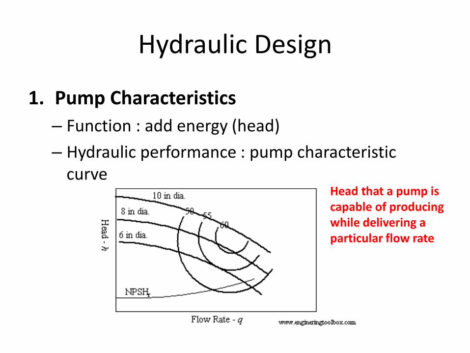
1. Pump Characteristics
– Function : add energy (head)
– Hydraulic performance : pump characteristic curve
Head that a pump is capable of producing while delivering a particular flow rate
2. System characteristics
Water must be given head in order to:
• Be lifted physically (static lift)
• Overcome the energy losses due to pipe friction and local losses at bends, valves etc.
• Provide velocity head if the water is discharged to the atmosphere at significant velocity
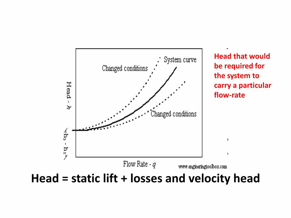
Head = static lift + losses and velocity head
Head that would be required for the system to carry a particular flow-rate
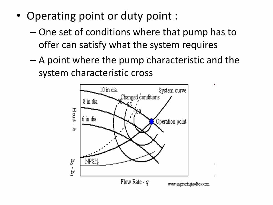
• Operating point or duty point :
– One set of conditions where that pump has to offer can satisfy what the system requires
– A point where the pump characteristic and the system characteristic cross
3. Power
The power required at the operating point can be derived from the operating flow-rate and head in conjunction with the pump’s efficiency
P = ρ g Q H
Pump gives power to the water and it requires power usually from electrical power
Power supplied = 1/η(ρ g Q H)
• Design considerations: – Water level in the sump is not constant pump
drains the sump; the level goes down the static head increase
– Velocity head is sometimes insignificant in relation to the losses and is ignored
– Instead of discharging to atmosphere at the manhole, the raising main outlet might be “drowned” (submerged in a tank into the liquid is being pumped static lift must be measured up to the liquid surface in the tank; this surface doesn’t have velocity (velocity head will not be included)
4. Pumps configurations
– Parallel
– Series
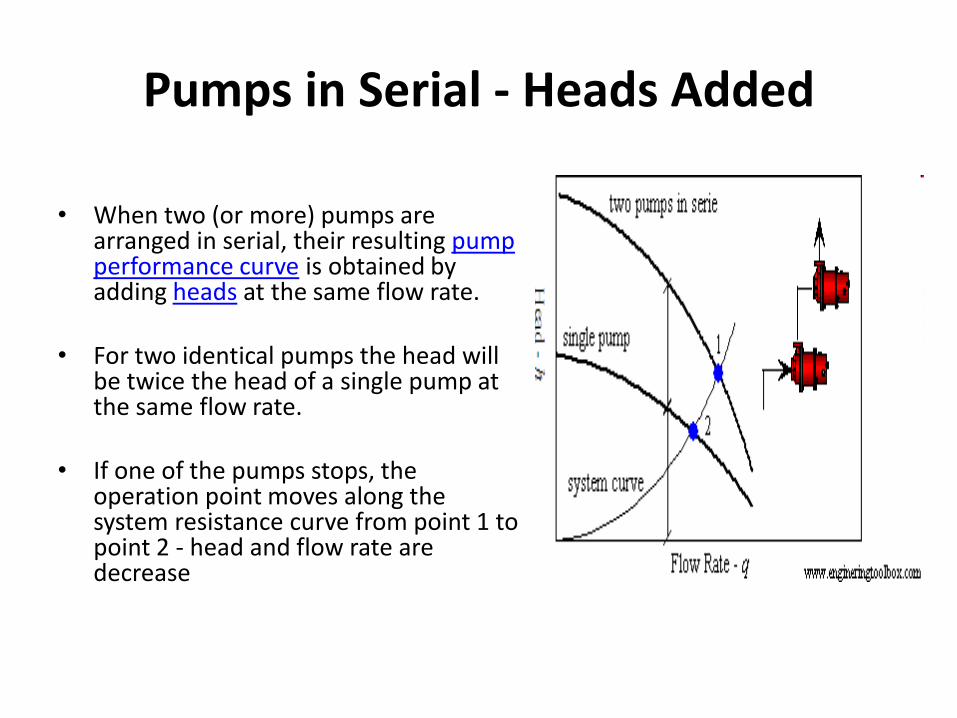
Pumps in Serial - Heads Added
• When two (or more) pumps are
arranged in serial, their resulting pump performance curve is obtained by adding heads at the same flow rate.
• For two identical pumps the head will
be twice the head of a single pump at the same flow rate.
• If one of the pumps stops, the operation point moves along the system resistance curve from point 1 to point 2 - head and flow rate are decrease
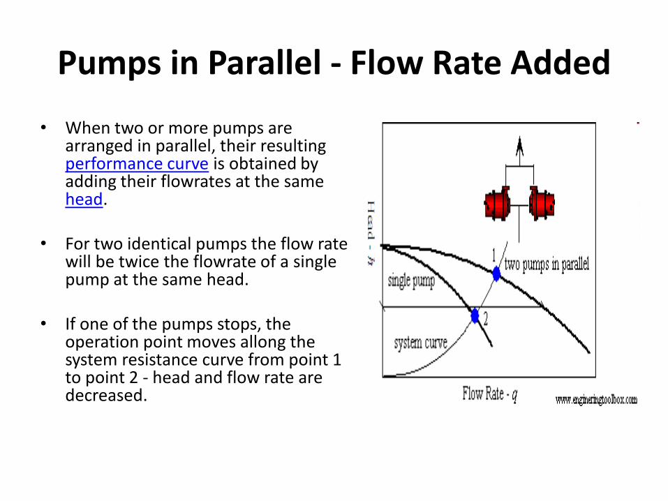
Pumps in Parallel - Flow Rate Added
• When two or more pumps are arranged in parallel, their resulting performance curve is obtained by adding their flowrates at the same head.
• For two identical pumps the flow rate
will be twice the flowrate of a single pump at the same head.
• If one of the pumps stops, the operation point moves allong the system resistance curve from point 1 to point 2 - head and flow rate are decreased.
5. Suction and Delivery Pipes • Suction pipe : pipe on the upstream, or on inlet side of
a pump – When suction pipe is short, it is not considered separately; – It is also common for pump to be below the water level in
sump ensure the pump remained “primed” (full of liquid)
– It is important to keep the pump is at a higher level than sump level ensure the pressure on the suction side of pump stay well above the vapor pressure of the liquid Avoid CAVITATION
• Delivery pipe :pipe on the downstream, or outlet side
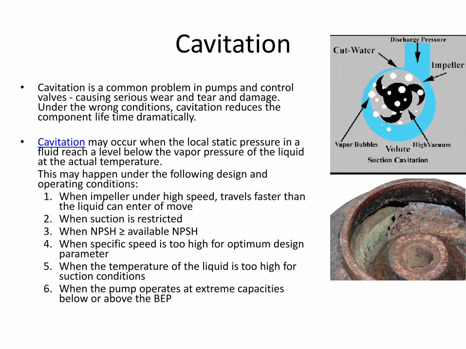
Cavitation
• Cavitation is a common problem in pumps and control valves - causing serious wear and tear and damage. Under the wrong conditions, cavitation reduces the component life time dramatically.
• Cavitation may occur when the local static pressure in a fluid reach a level below the vapor pressure of the liquid at the actual temperature.
This may happen under the following design and operating conditions:
1. When impeller under high speed, travels faster than the liquid can enter of move
2. When suction is restricted 3. When NPSH ≥ available NPSH 4. When specific speed is too high for optimum design
parameter 5. When the temperature of the liquid is too high for
suction conditions 6. When the pump operates at extreme capacities
below or above the BEP
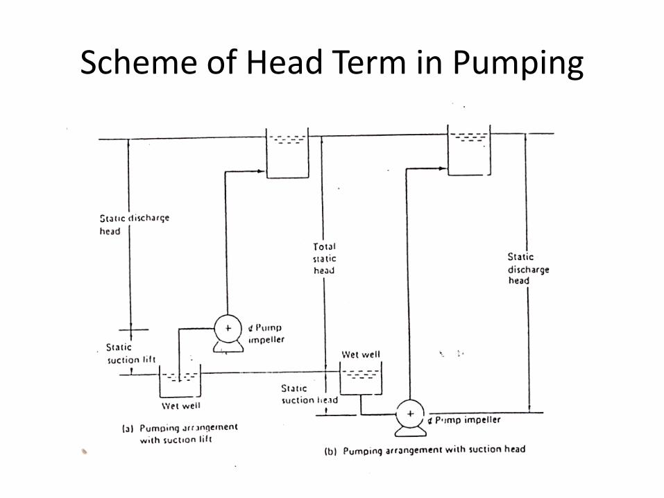
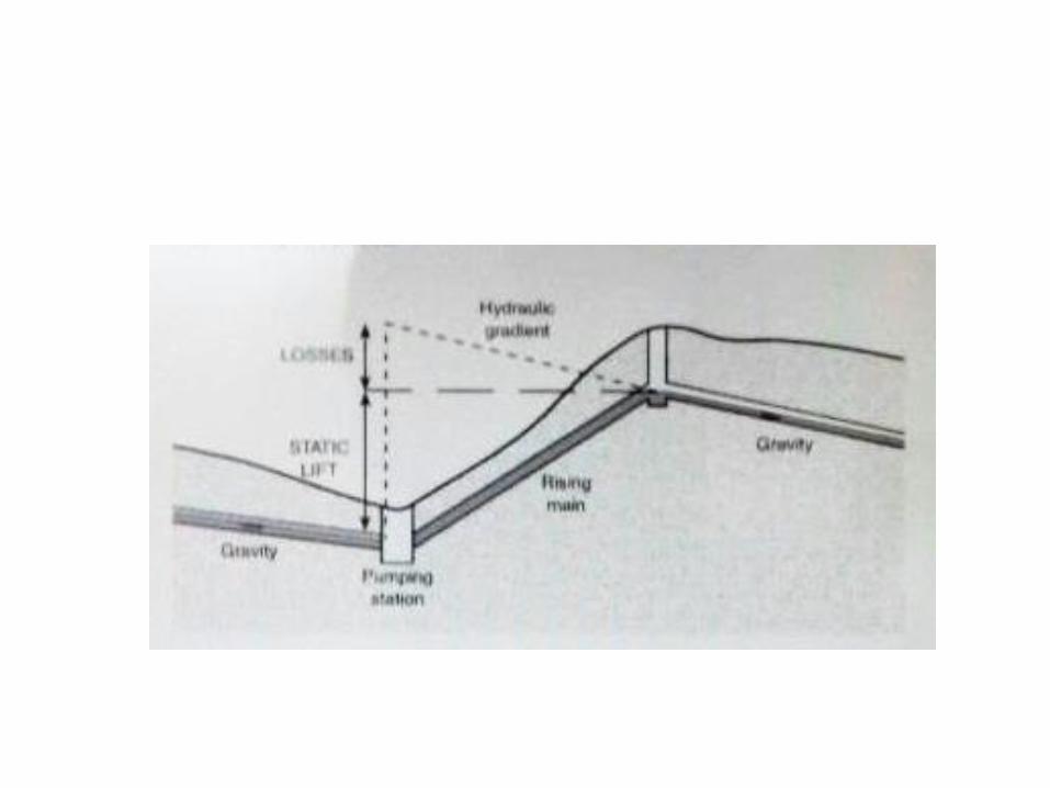
Scheme of Head Term in Pumping
Rising Mains
1. Differences from gravity sewer Hydraulic gradient • Hydraulic gradient is not equal to the pipe slope
since – in the part-full pipe flow, the hydraulic gradient
coincides with the water surface – In uniform flow, is parallel to the invert of the pipe
• Hydraulic gradient is downward in the direction of flow
• The pipe can be laid at a constant depth and follow the profile of the ground
Flow is not continuous Conditions:
– No flow water stands in the rising mains (solid deposition) ; requires scouring velocity
– A number of alternative flows depending on how many pumps are operating
• Scouring velocity 0.75 m/s (min 0.5 m/s if flow 1.2 m/s for
several hours a day) • Minimum suitable diameter : 100mm • Maximum retained time 12 hours (avoid septicity) • When the range of flow is high : dual rising mains
maintain velocity to prevent deposition • Extremely high or low pressures resulting from surge wave
as the consequences of starting and stopping the flow
Power Input
• Power is required to create flow in the system
• Power is needed as long as the system operates economic design.
• Diameter pipe : Smaller cheaper; higher velocity; higher losses HIGHER POWER
• Economic decision considers : design life, time-related comparisons of capital and operating cost
The pipes are under pressure
• No open access to rising mains
• Always full
• Diameter tends to be smaller
• Depth of excavation less than a gravity pipe (usually not full and must slope downward)
2. Design features • Common material : ductile iron, steel and some plastics • Flexible joints (allow for differential settlement and other
of underground stress) – Valve and other hydraulic features are needed: – Isolating valve, a “sluice” or gate valve : near the start of the
rising main : pumping station pipework can be worked on without emptying the main
– Non return (or reflux) valve : prevent back flow when pumping stop
– Air release valve : summits (local high point) in the rising main
• Washout facilities (for emptying the main) at low point of the mains
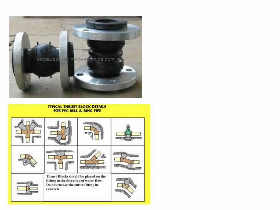
• Trust block : withstand the forces created when water is forced to change direction
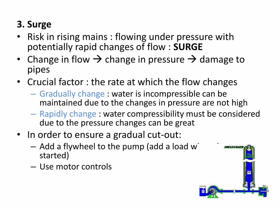
3. Surge • Risk in rising mains : flowing under pressure with
potentially rapid changes of flow : SURGE • Change in flow change in pressure damage to
pipes • Crucial factor : the rate at which the flow changes
– Gradually change : water is incompressible can be maintained due to the changes in pressure are not high
– Rapidly change : water compressibility must be considered due to the pressure changes can be great
• In order to ensure a gradual cut-out: – Add a flywheel to the pump (add a load when the pump
started) – Use motor controls
Types of pump
Centrifugal pump • Impeller has special design to avoid clogging
lower efficiencies (50-60% for wastewater pump) • Flowrate 7-700 L/s • Head: 3-45 m • Low speed around 900 rpm • Require priming (filling with water before
pumping) • Must installed below the lowest level of
wastewater to be pump
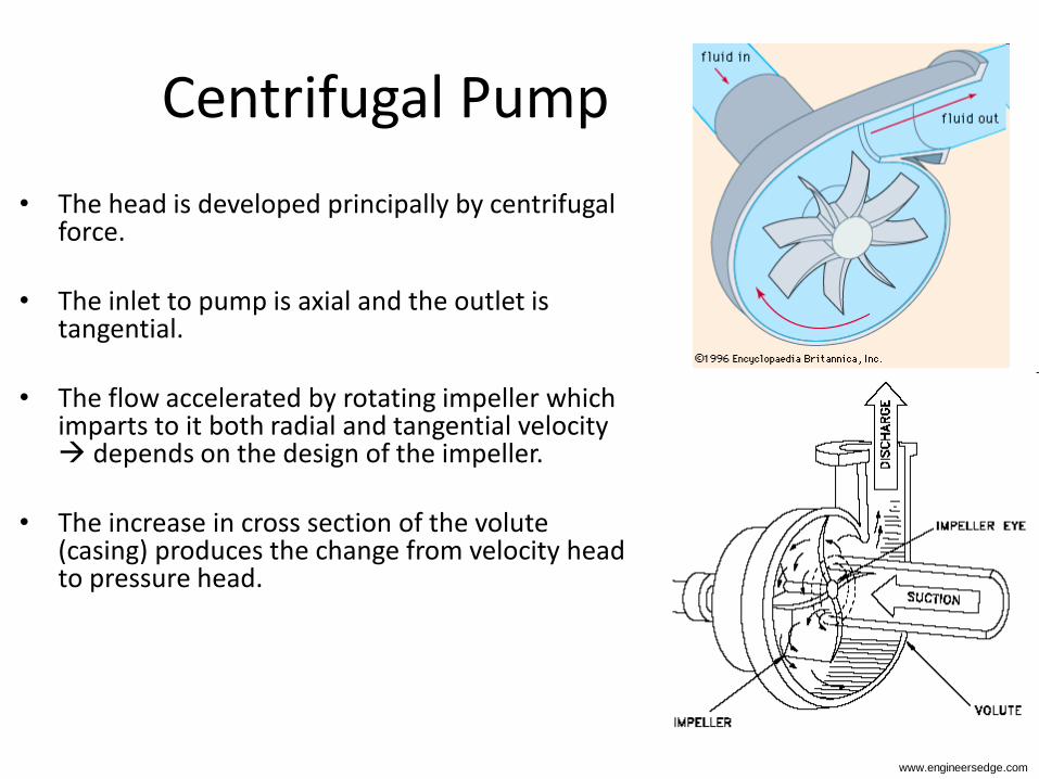
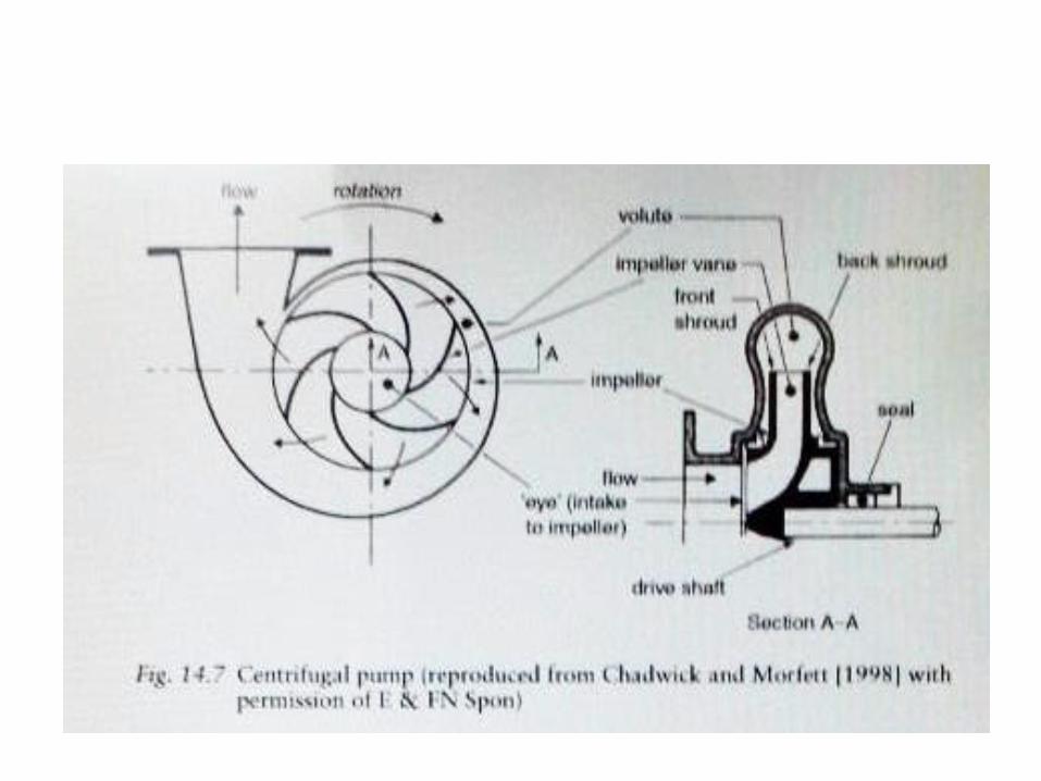
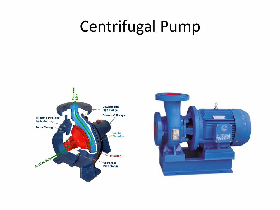
Centrifugal Pump
• The head is developed principally by centrifugal force.
• The inlet to pump is axial and the outlet is tangential.
• The flow accelerated by rotating impeller which imparts to it both radial and tangential velocity depends on the design of the impeller.
• The increase in cross section of the volute (casing) produces the change from velocity head to pressure head.
www.engineersedge.com
Centrifugal Pump
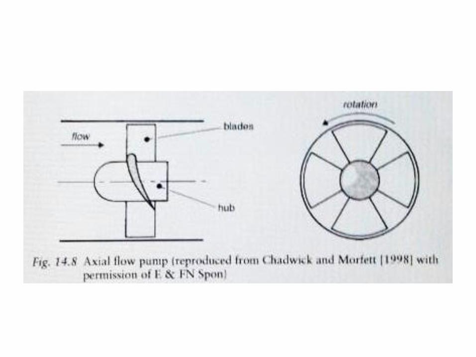
Axial-flow pump
• High flow rate
• Low head
• High efficiency 75-90%
• Suffer a rapid decrease in head with increase discharge
• Appropriate for stormwater
Mixed flow pumps
• The direction in which the water is force by impeller is at an intermediate angle, so flow is partly radial and partly axial
• Recommended for medium head 6-18m
• Appropriate for storm water
Pumping Stations Type
• Wet-well station:
Employ either suspended or submersible pump.
• Dry-well station:
Employ either dry-well of self-primming centrifugal pump. The dry-well centrifugal pump operate within the dry-well adjacent to the wet-well
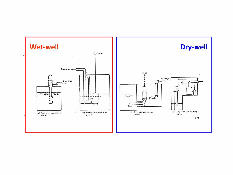
Dry-well Wet-well
Number of pumps
The appropriate number of pumps is a function of : • the need for standby pumps to be available to
cover for faults • the flow capacity of the pumps, alone and in
parallel, determined from the calculations covered in Section 14.3
• the variation in inflow.
Simplest pumping station consists of a duty/standby arrangement.
Control
• All pumping stations require some control system. • The basic requirement is sensing of upper and lower
sump level, and the consequent starting and stopping of the pumps.
• More pumps more complex starting and stopping procedures, the complexity of the control system increases.
• Methods of sensing water level are by : – ultrasonic detector, – float- switches and – electrodes.
• Safe frequency of operation of the electric motor starter is limited; 6 and 12 starts/hour.

Sump Volume
To determine the required sump volume (V) between ‘stop’ and ‘start’ levels,
t1 : the time taken to fill the sump while the pump is idle is given by:
t1 = V/QI
t2 : the time taken to pump out the sump :
t2 = V (Qo - QI)
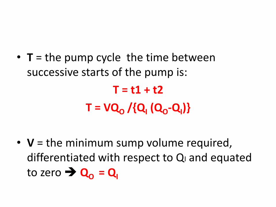
• T = the pump cycle the time between successive starts of the pump is:
T = t1 + t2
T = VQO /{QI (QO-QI)}
• V = the minimum sump volume required, differentiated with respect to QI and equated to zero QO = QI
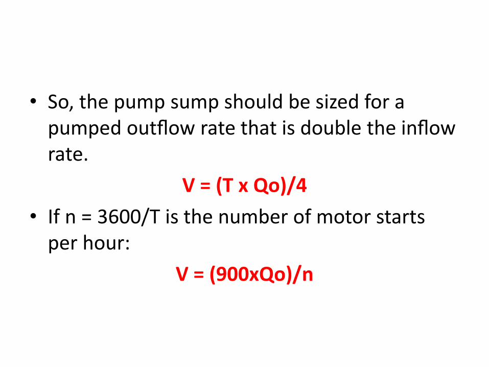
• So, the pump sump should be sized for a pumped outflow rate that is double the inflow rate.
V = (T x Qo)/4
• If n = 3600/T is the number of motor starts per hour:
V = (900xQo)/n
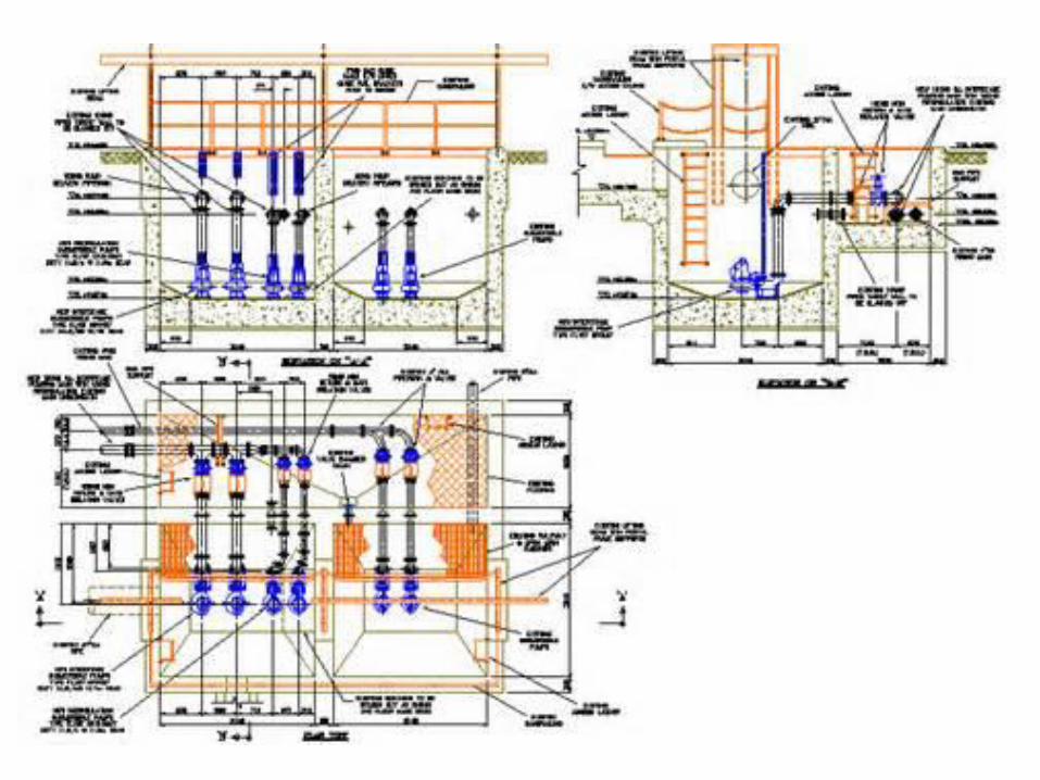
Flow Arragement
Within a pumping station : • Pipework is usually ductile iron with flanged joints. • Flexible joints should be placed outside walls to allow for differential
settlement. • For each pump there should be a sluice valve on the suction and delivery
sides for isolating the pump. • The base of the sump is usually given quite steep slopes to limit
deposition of solids. • In large pumping stations require preliminary treatment remove large
solids (screens) • All pumping stations should have an emergency overflow in case of
complete failure of the pumps, with storage for wastewater inflow during emergency repairs.
• In combined systems, necessary to provide an overflow for storm flows. This would be based on the same principles as other CSOs, described in Chapter 12.
Maintenance
• Priorities in taking maintenance requirements into account in design are to ensure that:
• Possibility to isolate and remove the main elements of pipework and equipment.
• Access to allow the pumps to be lifted out vertically; this is especially true for submersible pumps which it must be possible to lift out with ease
• Problems caused by solids can be overcome (suitable pumps, pipe sizes, access to clear blockages)
• Emergencies caused by breakdown, power failure, etc. can be coped with.
• The possibility of power failure needs to be taken into account. Provision of a standby generator, or a diesel-powered pump in larger stations, is a common precaution.
• An important element in maintenance is monitoring performance. Small to medium-sized pumping stations are usually controlled from the wastewater treatment plant that they serve, by telemetry.
• The types of information likely to be communicated are: – failure in the electricity supply
– pump failure
– unusually high levels in the wet well
– flooding of the dry well
– operation of the overflow.

Net Positive Suction Head - NPSH
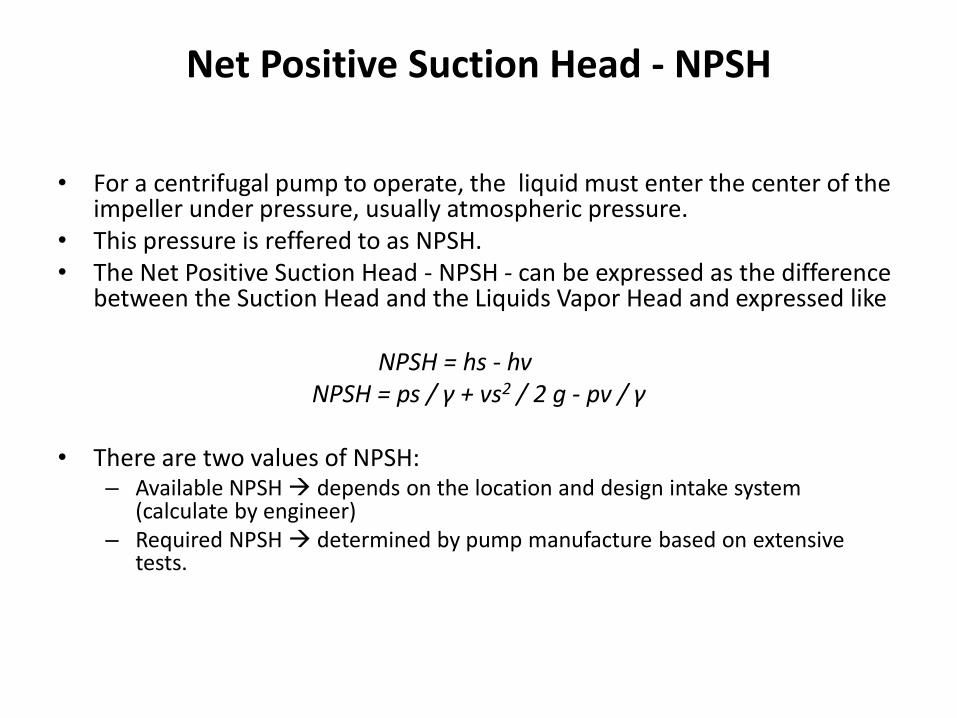
• For a centrifugal pump to operate, the liquid must enter the center of the impeller under pressure, usually atmospheric pressure.
• This pressure is reffered to as NPSH. • The Net Positive Suction Head - NPSH - can be expressed as the difference
between the Suction Head and the Liquids Vapor Head and expressed like
NPSH = hs - hv NPSH = ps / γ + vs2 / 2 g - pv / γ
• There are two values of NPSH:
– Available NPSH depends on the location and design intake system (calculate by engineer)
– Required NPSH determined by pump manufacture based on extensive tests.
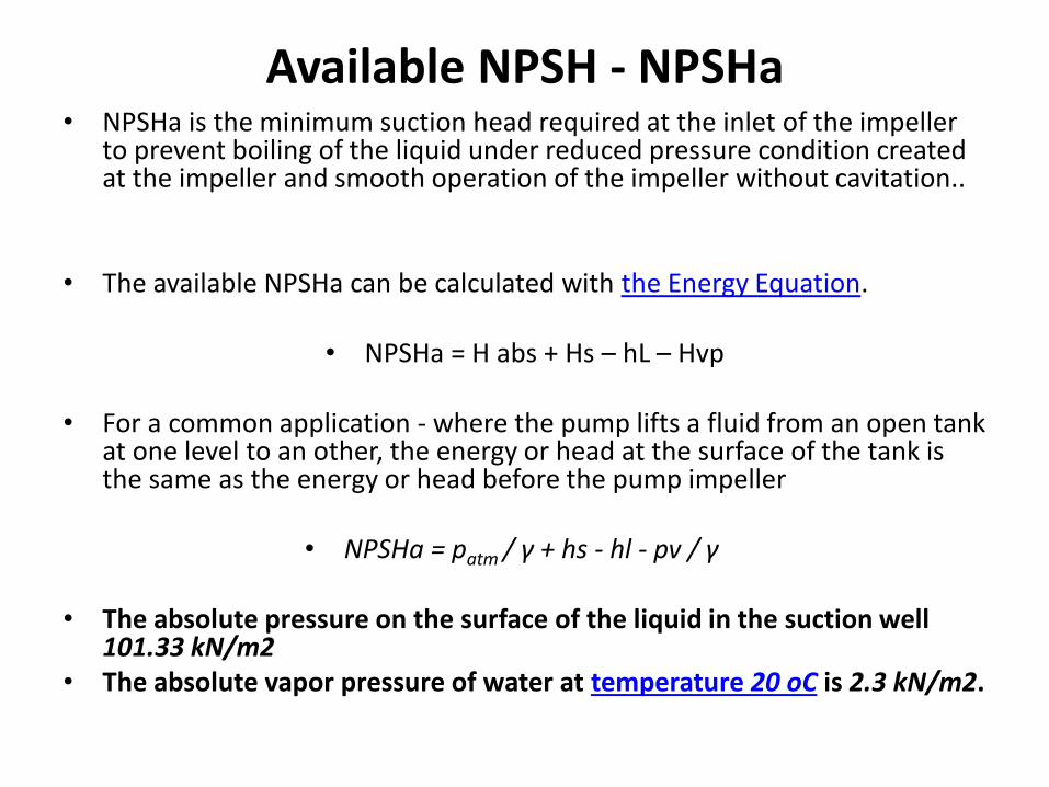
Available NPSH - NPSHa • NPSHa is the minimum suction head required at the inlet of the impeller
to prevent boiling of the liquid under reduced pressure condition created at the impeller and smooth operation of the impeller without cavitation..
• The available NPSHa can be calculated with the Energy Equation.
• NPSHa = H abs + Hs – hL – Hvp
• For a common application - where the pump lifts a fluid from an open tank at one level to an other, the energy or head at the surface of the tank is the same as the energy or head before the pump impeller
• NPSHa = patm / γ + hs - hl - pv / γ
• The absolute pressure on the surface of the liquid in the suction well 101.33 kN/m2
• The absolute vapor pressure of water at temperature 20 oC is 2.3 kN/m2.
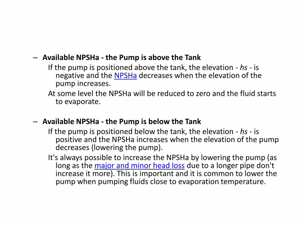
– Available NPSHa - the Pump is above the Tank If the pump is positioned above the tank, the elevation - hs - is
negative and the NPSHa decreases when the elevation of the pump increases.
At some level the NPSHa will be reduced to zero and the fluid starts to evaporate.
– Available NPSHa - the Pump is below the Tank
If the pump is positioned below the tank, the elevation - hs - is positive and the NPSHa increases when the elevation of the pump decreases (lowering the pump).
It's always possible to increase the NPSHa by lowering the pump (as long as the major and minor head loss due to a longer pipe don't increase it more). This is important and it is common to lower the pump when pumping fluids close to evaporation temperature.
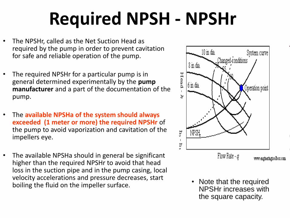
Required NPSH - NPSHr • The NPSHr, called as the Net Suction Head as
required by the pump in order to prevent cavitation for safe and reliable operation of the pump.
• The required NPSHr for a particular pump is in general determined experimentally by the pump manufacturer and a part of the documentation of the pump.
• The available NPSHa of the system should always exceeded (1 meter or more) the required NPSHr of the pump to avoid vaporization and cavitation of the impellers eye.
• The available NPSHa should in general be significant higher than the required NPSHr to avoid that head loss in the suction pipe and in the pump casing, local velocity accelerations and pressure decreases, start boiling the fluid on the impeller surface. • Note that the required
NPSHr increases with the square capacity.

Cavitation
• Cavitation is a common problem in pumps and control valves - causing serious wear and tear and damage. Under the wrong conditions, cavitation reduces the component life time dramatically.
• Cavitation may occur when the local static pressure in a fluid reach a level below the vapor pressure of the liquid at the actual temperature.
This may happen under the following design and operating conditions:
1. When impeller under high speed, travels faster than the liquid can enter of move
2. When suction is restricted 3. When NPSH ≥ available NPSH 4. When specific speed is too high for optimum design
parameter 5. When the temperature of the liquid is too high for
suction conditions 6. When the pump operates at extreme capacities
below or above the BEP
• Cavitation causes reduction in flow and under serious conditions the pump may lose its prime, cause pitting on the impeller surface, rattling or pinging noise and eventual breakdown of pumping equipment.
• Cavitation can in general be avoided by • increasing the distance between the actual local static
pressure in the fluid - and the vapor pressure of the fluid at the actual temperature This can be done by: – reengineering components initiating high speed velocities and low
static pressures – increasing the total or local static pressure in the system – reducing the temperature of the fluid