Embed Size (px)
Citation preview

8-2SectionPulse I/O Board
196
8-1-9 Internal CircuitsPulse Inputs
Phases A and B
Input voltageswitch. See Note.
Internal circuit of phase A or B
Internal circuit of ZInput voltageswitch. See Note.
Phase Z
Note ON: Line driver inputOFF: 24-V DC input
4.4 kΩ
3.0 kΩ
External Outputs
Internal circuit of Output
Sourcing/Sinking switching signal
0.75 A
0.75 A
Note In the above figure, A is active when sourcing outputs are set, and B is activewhen sinking outputs are set.
8-2 Pulse I/O Board
8-2-1 ModelName Model Specifications
Pulse I/O Board CQM1H-PLB21 Two pulse input points and twopulse output points
8-2-2 FunctionThe Pulse I/O Board is an Inner Board that supports two pulse inputs and twopulse outputs.
Pulse inputs 1 and 2 can be used as high-speed counters to count pulses input ateither 50 kHz (signal phase) or 25 kHz (differential phase). Interrupt processingcan be performed based on the present values (PV) of the counters.
Input ModeThe following three Input Modes are available:
• Differential Phase Mode (4x)
Pulse Inputs 1 and 2

8-2SectionPulse I/O Board
197
• Pulse/Direction Mode
• Up/Down Mode
InterruptsThe Board can be set to execute an interrupt subroutine when the value of thehigh-speed counter matches a specified target value, or an interrupt subroutinewhen the PV falls within a specified comparison range.
Two 10 Hz to 50 kHz pulses can be output from port 1 and port 2. Both fixed andvariable duty factors can be used.
• The fixed duty factor can raise or lower the frequency of the output from 10 Hzto 50 kHz smoothly.
• The variable duty factor enables pulse output to be performed using a duty fac-tor ranging from 1% to 99%.
Note While pulse inputs and pulse outputs can be performed simultaneously, it is notpossible to use all high-speed counter and pulse output functionality at the sametime. The Port Mode Setting (High-speed Counter Mode/Simple PositioningMode) in the PC Setup (DM 6611) will determine which has full functionality en-abled.
Two pulse inputs (high-speed counter) and two pulse outputs can be used simul-taneously via ports 1 and 2. To determine which has functional priority, the ap-propriate Port Mode setting must be entered in the PC Setup (DM 6611).
Mode Content High-speed counterfunctions
Pulse output functions DM 6611setting
ReadingPV withPRV(62)
High-speed
counterinterrupts
withCTBL(63)
Notrapezoidal
acceleration/deceleration(SPED(64))
Identicalacceleration/deceleration
rates(PLS2(––))
Separateacceleration/deceleration
rates(ACC(––))
g
High-speedCounterMode
High-speed countergiven priority.
All high-speed counterfunctions are enabled.
Trapezoidal acceleration/deceleration for pulseoutputs is limited.
Yes Yes Yes Mode 0disabled(Modes 1 to 3enabled) Seenote 1.
0000Hex
SimplePosition-ingMode
Pulse output givenpriority.
All pulse output functionsare enabled.
Interrupts for thehigh-speed counter aredisabled.
Yes No Yes Yes Yes 0001Hex
Note 1. Mode 0: Acceleration + Independent Mode; Mode 1: Acceleration + Contin-uous Mode; Mode 2: Deceleration + Independent Mode; Mode 3: Decelera-tion + Continuous Mode.
2. The port modes for both ports 1 and 2 is always set to the same mode, i.e.,either High-speed Counter Mode and Simple Positioning Mode. The modecannot be set separately for each port.
Pulse Outputs 1 and 2
Ports 1 and 2

8-2SectionPulse I/O Board
198
8-2-3 System Configuration
Pulse I/O Board
Pulse input 2
Incremental encoder
Motordriver
Pulseoutput 2
Motor Motor
Motordriver
Pulse input 1
Incremental encoder
Pulseoutput 1
8-2-4 Applicable Inner Board SlotThe Pulse I/O Board can only be mounted in slot 2 (right slot) of the CQM1H-CPU51/61 CPU Unit.
Slot 1: No Slot 2: OK
Pulse I/O Board
8-2-5 Names and FunctionsThe CQM1H-PLB21 Pulse I/O Board has a CN1 connector for pulse input 1 andpulse output 1, and a CN2 connector for pulse input 2 and pulse output 2.
CQM1H-PLB21 Pulse I/O Board
CN1: Pulse input/output 1
CN2: Pulse input/output 2
Compatible connector
Socket: XM2D-1501 (OMRON)
Hood: XM2S-1511 (OMRON)
Two Sockets and two Hoods areprovided as standard with thePulse I/O Board.
8-2SectionPulse I/O Board
199
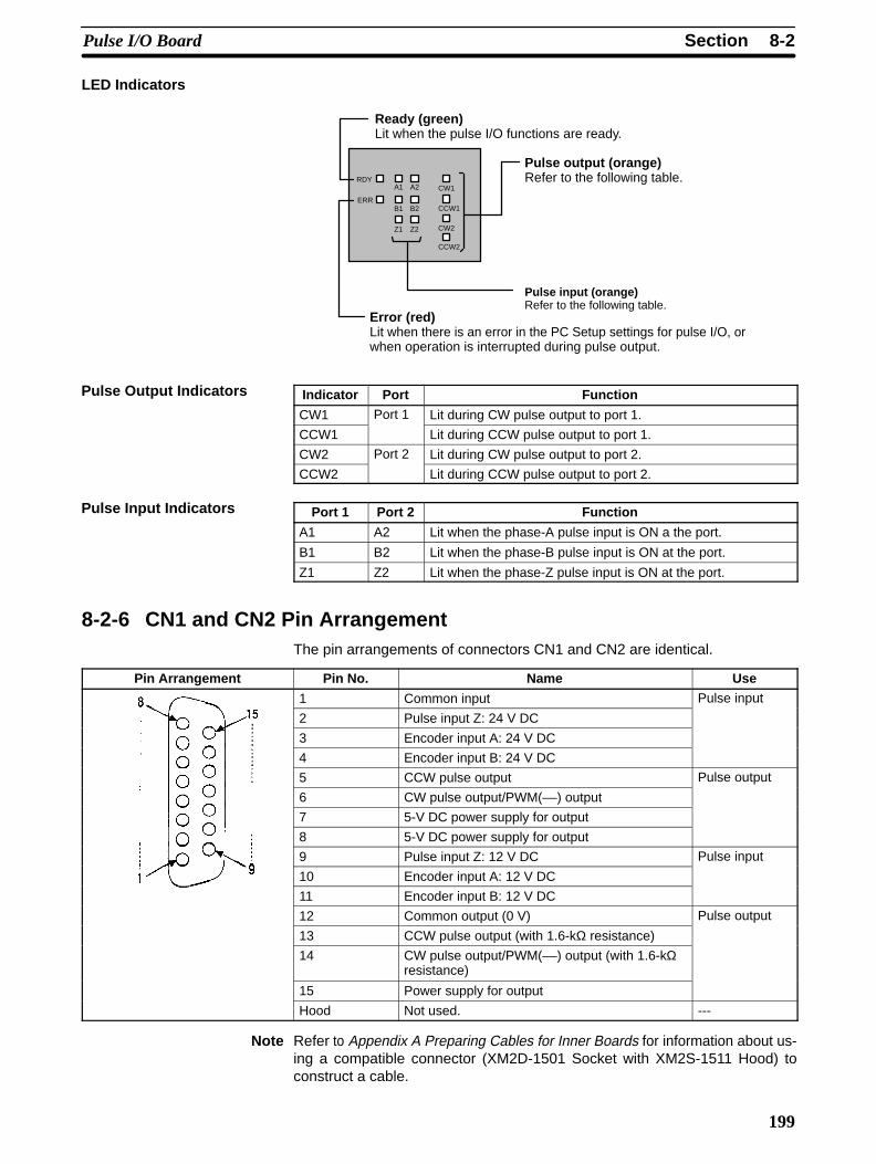
LED Indicators
Ready (green)Lit when the pulse I/O functions are ready.
Error (red)Lit when there is an error in the PC Setup settings for pulse I/O, orwhen operation is interrupted during pulse output.
Pulse output (orange)Refer to the following table.
Pulse input (orange)Refer to the following table.
CW1
CCW1
CW2
CCW2
RDY
ERR
Z1 Z2
B1 B2
A1 A2
Indicator Port Function
CW1 Port 1 Lit during CW pulse output to port 1.
CCW1 Lit during CCW pulse output to port 1.
CW2 Port 2 Lit during CW pulse output to port 2.
CCW2 Lit during CCW pulse output to port 2.
Port 1 Port 2 Function
A1 A2 Lit when the phase-A pulse input is ON a the port.
B1 B2 Lit when the phase-B pulse input is ON at the port.
Z1 Z2 Lit when the phase-Z pulse input is ON at the port.
8-2-6 CN1 and CN2 Pin ArrangementThe pin arrangements of connectors CN1 and CN2 are identical.
Pin Arrangement Pin No. Name Use
1 Common input Pulse input
2 Pulse input Z: 24 V DC
3 Encoder input A: 24 V DC
4 Encoder input B: 24 V DC
5 CCW pulse output Pulse output
6 CW pulse output/PWM(––) output
7 5-V DC power supply for output
8 5-V DC power supply for output
9 Pulse input Z: 12 V DC Pulse input
10 Encoder input A: 12 V DC
11 Encoder input B: 12 V DC
12 Common output (0 V) Pulse output
13 CCW pulse output (with 1.6-kΩ resistance)
14 CW pulse output/PWM(––) output (with 1.6-kΩresistance)
15 Power supply for output
Hood Not used. ---
Note Refer to Appendix A Preparing Cables for Inner Boards for information about us-ing a compatible connector (XM2D-1501 Socket with XM2S-1511 Hood) toconstruct a cable.
Pulse Output Indicators
Pulse Input Indicators
8-2SectionPulse I/O Board
200
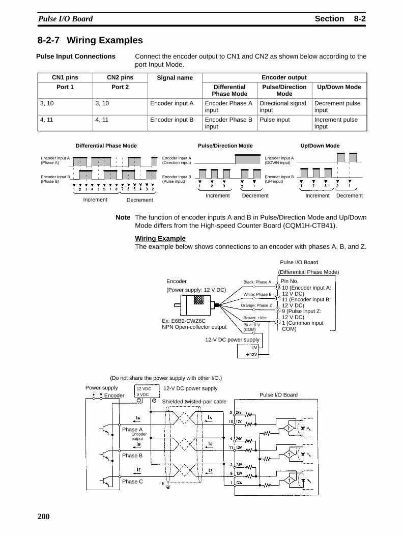
8-2-7 Wiring Examples
Connect the encoder output to CN1 and CN2 as shown below according to theport Input Mode.
CN1 pins CN2 pins Signal name Encoder output
Port 1 Port 2
g
DifferentialPhase Mode
Pulse/DirectionMode
Up/Down Mode
3, 10 3, 10 Encoder input A Encoder Phase Ainput
Directional signalinput
Decrement pulseinput
4, 11 4, 11 Encoder input B Encoder Phase Binput
Pulse input Increment pulseinput
Encoder input A(Phase A)
Encoder Input B(Phase B)
Differential Phase Mode Up/Down Mode
Encoder input A(DOWN input)
Encoder input B(UP input)
Pulse/Direction Mode
Encoder input A(Direction input)
Encoder input B(Pulse input)
DecrementIncrementDecrementIncrementDecrementIncrement
Note The function of encoder inputs A and B in Pulse/Direction Mode and Up/DownMode differs from the High-speed Counter Board (CQM1H-CTB41).
Wiring ExampleThe example below shows connections to an encoder with phases A, B, and Z.
Pulse I/O Board
10 (Encoder input A:12 V DC)
Pin No.
(Differential Phase Mode)
Encoder
(Power supply: 12 V DC)
Ex: E6B2-CWZ6CNPN Open-collector output
Black: Phase A
12-V DC power supply
Orange: Phase Z
White: Phase B
Blue: 0 V(COM)
Brown: +Vcc1 (Common inputCOM)
11 (Encoder input B:12 V DC)9 (Pulse input Z:12 V DC)
Power supplyEncoder Pulse I/O Board
Shielded twisted-pair cable
(Do not share the power supply with other I/O.)
12-V DC power supply
Phase AEncoderoutput
12 VDC
0 VDC
Phase B
Phase C
Pulse Input Connections
!
8-2SectionPulse I/O Board
201
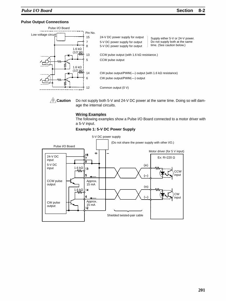
Pulse Output Connections
Pulse I/O Board
Low voltage circuitPin No.15 24-V DC power supply for output Supply either 5-V or 24-V power.
Do not supply both at the sametime. (See caution below.)
13 CCW pulse output (with 1.6 kΩ resistance.)
7 5-V DC power supply for output8 5-V DC power supply for output
5 CCW pulse output
14 CW pulse output/PWM(––) output (with 1.6 kΩ resistance)
6 CW pulse output/PWM(––) output
12 Common output (0 V)
1.6 kΩ(1/2 W)
1.6 kΩ(1/2 W)
Caution Do not supply both 5-V and 24-V DC power at the same time. Doing so will dam-age the internal circuits.
Wiring ExamplesThe following examples show a Pulse I/O Board connected to a motor driver witha 5-V input.
Example 1: 5-V DC Power Supply
Pulse I/O Board
24-V DCinput
5-V DCinput
Approx.15 mA
Approx.15 mA
5-V DC power supply
Motor driver (for 5 V input)
Ex: R=220 Ω
CCWinput
(Do not share the power supply with other I/O.)
Shielded twisted-pair cable
CWinput
1.6 kΩ
1.6 kΩ
CCW pulseoutput
CW pulseoutput

!
8-2SectionPulse I/O Board
202
Example 2: 24-V DC Power Supply
Pulse I/O Board
24-V DCinput
Approx.12 mA
Approx.12 mA
24-V DC power supply
Motor driver (for 5 V input)
Ex: R=220 Ω
(Do not share the power supply with other I/O.)
Note Here, a 5-V input motor driver is being used with a 24-Vpower supply. The internal resistance at the Pulse I/OBoard (1.6 kΩ) is thus used. Care must be taken to avoidproblems caused by the drive current at the motor driver.
1.6 kΩ
1.6 kΩ
5-V DC input
CCW pulseoutput
CW pulseoutput
Caution The 5-V DC or 24-V DC power supply for the outputs must be connectedcorrectly.
• Connect a 7 to 30 mA load to the pulse output. Use a bypass resistor if the loadis smaller than 7 mA.
• The pulse output circuits on pins 13 and 14 have a built-in resistance of 1.6 kΩ(1/2 W). Connect the pulse outputs as shown below according to the powersupply and the motor driver specifications.
Open Collector Output
Output transistor
Output from Open Collector 1.6 k Ω Series Resistance
Output7 to 30 mA
Output
7 to 30 mA
Pulse Output ConnectionPrecautions

8-2SectionPulse I/O Board
203
The internal 1.6-kΩ (1/2 W) resistance can be used as bypass resistance inthe following way.
Example: 7 mA output transistor current = 4 mA load current + 3 mA bypass current
Pulse I/O Board
Approx. 3 mA
Approx.3 mA
5-V DC power supply
Motor driver (for 5 V input)
Load current =Approx. 4 mA
CCWinput
CWinput
Shielded twisted-pair cable
Approx. 4 mA
Approx. 4 mA
1.6 kΩ
1.6 kΩ
24-V DC input
5-V DC input
CCW pulseoutput
CW pulseoutput
Approx.7 mA
Approx.7 mA
• The transistors of the internal circuits of the pulse output section are OFF whenpulse output is stopped.
Output transistor
During pulse output
8-2SectionPulse I/O Board
204
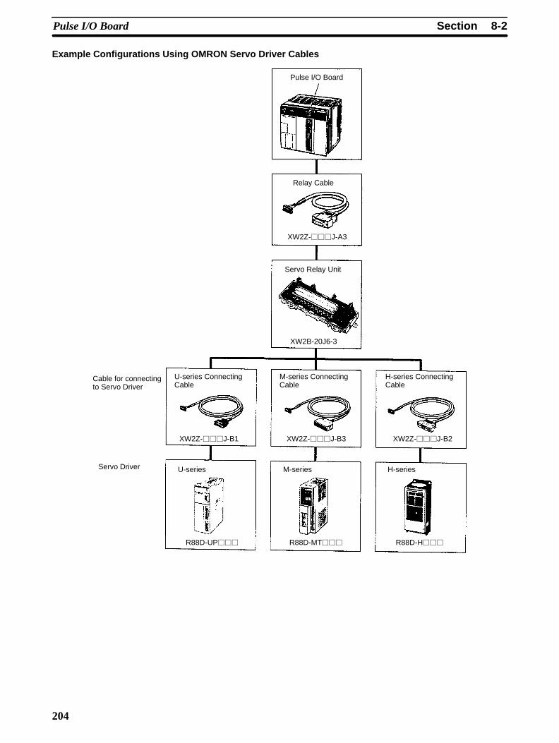
Example Configurations Using OMRON Servo Driver Cables
Pulse I/O Board
Relay Cable
Servo Relay Unit
U-series ConnectingCable
M-series ConnectingCable
H-series ConnectingCable
U-series M-series H-series
Cable for connectingto Servo Driver
Servo Driver
XW2Z-J-A3
XW2B-20J6-3
XW2Z-J-B1 XW2Z-J-B3 XW2Z-J-B2
R88D-UP R88D-MT R88D-H

8-2SectionPulse I/O Board
205
8-2-8 SpecificationsItem Specifications
Name Pulse I/O Board
Model number CQM1H-PLB21
Compatible CPU Units CQM1H-CPU51/61
Unit classification CQM1H-series Inner Board
Mounting locations and number ofBoards
One in Inner Board slot 2 (right slot)
Pulse inputs 2 inputs (Refer to High-speed Counter Pulse Inputs below for details.)
Pulse outputs 2 outputs (Refer to Pulse Outputs below for details.)
Setting section None
Indicators Front: 12 LEDs 1 each of Ready (RDY) and Error (ERR)
2 each of phase A (A), phase B (A), phase Z (Z),CW pulse (CW), and CCW pulse (CCW).
Front connection section Connectors CN1 and CN2 (Compatible connector: Sockets & Hoods providedas standard accessories.)
Current consumption (Supplied fromPower Supply Unit)
5 V DC 160 mA max.
Dimensions 25 × 110 × 107 mm (W × H × D)
Weight 90 g max.
Standard accessories Sockets: XM2D-1501 (OMRON) x 2Hoods: XM2S-1511 (OMRON) x 2
High-speed Counter SpecificationsCounter Specifications
Item Specifications
Number of counters 2 counters (ports)
Input Modes (Set for each port inthe PC Setup.)
Differential phase input Pulse/Direction input Up/Down pulse input
Input pinN
Port 1 Port 2 ---No. 3/10 3/10 A-phase input Direction input Decrement pulse input
4/11 4/11 B-phase input Pulse input Increment pulse input
2/9 2/9 Z-phase input Reset input Reset input
Input method Phase difference multipleof 4 (Fixed)
Single-phase pulse +direction
Single-phase pulse x 2
Count frequency 25 KHz 50 KHz 50 KHz
Count value Linear Mode: –8388608 to 8388607Ring Mode: 0 to 64999 (Maximum value can be set between 1 and 65000 withCTBL(63).)
Storage location of counter PV Port 1: IR 233 (leftmost digits) and IR 232 (rightmost digits)Port 2: IR 235 (leftmost digits) and IR 234 (rightmost digits)
Data format: 8-digit BCDLinear Mode: F8388608 to 8388607 (Leftmost digit is F Hex for negative numbers.)Ring Mode: 00000000 to 00064999
Controlh d
Target value Up to 48 target values and interrupt subroutine numbers registered.method Range comparison Up to 8 upper limits, lower limits, and interrupt subroutine numbers registered.
Counter reset method Phase-Z Signal + Software ResetA counter is reset on the first phase-Z signal input after its Reset Bit (see below) isturned ON.
Software ResetA counter is reset when its Reset Bit (see below) is turned ON.
Reset BitsPort 1: SR 25201Port 2: SR 25202

8-2SectionPulse I/O Board
206
Pulse Input Specifications
Item Specifications
Number of pulseinputs
2 inputs (Ports 1 and 2 = Pulses 1 to 2)
Signal names Encoder inputs A, encoder input B, pulse input Z
Input voltage Switched by means of connector pins (Can be specified separately for phases A, B, and Z.g
12 V DC±10% 24 V DC±10%
Input current Phase A, B Phase Z Phase A, B Phase Z
5 mA typical 12 mA typical 5 mA typical 12 mA typical
ON voltage 10.2 V DC min. 20.4 V DC min.
OFF voltage 3.0 V DC min. 4.0 V DC min.
Min. response pulseEncoder inputs A and BWaveform of encoder inputs A and BInput rise/fall time: 3 µsec. max.50 kHz, pulse with duty factor of 50%
10 µs min. 10 µs min.
3 µs max. 3 µs max.Relationship between phases A and B whenphase differential input is used.
Phase A T1, T2, T3, T4: 4.5 µs min.At least 4.5 µs must be allowed betweenPhase A and Phase B changes.
Pulse input ZPulse width must be 0.1 ms min.
0.1 ms min.
20 µs min.
Phase B
ON
50%
OFF
ON
50%
OFF
20 µs min.
ON
50%
OFF
ON
OFF
T1T2
T3T4
Pulse Output Specifications
Pulse output functions are determined by the output method, as indicated below.
Item Specifications
Fixed duty factor Variabled fWithout
trapezoidalacceleration/deceleration
Sameacceleration/deceleration
rates
Separateacceleration/deceleration
rates
duty factor
Instruction PULS(65)/SPED(64)
PLS2(––) PULS(65)/ACC(––)
PWM(––)
Outputfrequency
10 Hz to 50 kHz
10 Hz to 20 kHz forstepping motor
0 Hz to50 KHz
100 Hz to50 KHz
91.6 Hz,1.5 KHz,5.9 KHz
Outputfrequencypitch
1 or 10 Hz 10 Hz ---
Duty factor 50% fixed 1 to 99%
No. of outputpulses
1 to 16777215 ---
Acceleration/Decelerationrate
--- 10 Hz to 2 kHz (every 4.08 ms)
---
Pulse Output Functions

8-3SectionAbsolute Encoder Interface Board
207
Item Specifications
No. of pulse outputs 2 outputs (Ports 1 and 2 = Pulse outputs 1 and 2)
Signal names CW and CCW pulse output
Max. output frequency 50 kHz (20 kHz with stepping motor connected.)
External power supply 5 V DC±5% 30 mA min.24 V DC +10%/–15% 30 mA min.
Max. switching capacity NPN open collector, 30 mA/5 to 24 V DC±10%
Min. switching capacity NPN open collector, 7 mA/5 to 24 V DC±10%
Leakage current 0.1 mA max.
Residual voltage 0.4 V max.
Pulse outputspecifications
Min. pulse width
Pulsef
Switching current/Load power supply voltagefrequency 7 to 30 mA/5 V DC ±10% 7 to 30 mA/24 V DC +10%/–15%
tON tOFF tON tOFF
10 kpps max. 49.5 µs min. 48.5 µs min. 49.6 µs min. 46.0 µs min.
30 kpps max. 19.5 µs min. 18.5 µs min. 19.6 µs min. 16.0 µs min.
50 kpps max. 9.5 µs min. 8.5 µs min. 9.6 µs min. 6.0 µs min.
8-3 Absolute Encoder Interface Board
8-3-1 Model
Name Model Specifications
Absolute EncoderInterface Board
CQM1H-ABB21 2 inputs for absolute encoders
8-3-2 FunctionsThe Absolute Encoder Interface Board is an Inner Board that counts two graybinary code inputs from an absolute (ABS) rotary encoder.
The Absolute Encoder Interface Board reads binary gray codes (inverted binarycodes) input from an absolute encoder through ports 1 and 2 at a maximumcounting rate of 4 kHz, and performs processing according to the input values.
Operating ModesBCD Mode and 360° Mode.
ResolutionsOne of the following can be set: 8 bits (0 to 255), 10 bits (0 to 1023), or 12 bits (0to 4095). The resolution should be set to match that of the encoder connected.
InterruptsAn interrupt subroutine can be executed when the PV (present value) of the ab-solute high-speed counter matches a specified target value or lies within a speci-fied comparison range.
Note The use of an absolute encoder means that the position data can be retainedeven during power interrupts, removing the need to perform an origin returnwhen power is returned. In addition, the origin compensation function allows theuser to specify any position as the origin.
Output Specifications
Absolute High-speedCounter with InterruptFunction

2-2SectionPulse I/O Board
81
Operation will be as illustrated below when the program is executed.
Time
Pulse frequency (Hz)
2-2 Pulse I/O Board
2-2-1 ModelName Model Specifications
Pulse I/O Board CQM1H-PLB21 Two pulse input points and twopulse output points
2-2-2 FunctionThe Pulse I/O Board is an Inner Board that supports two pulse inputs and twopulse outputs.
Pulse inputs 1 and 2 can be used as high-speed counters to count pulses input ateither 50 kHz (signal phase) or 25 kHz (differential phase). Interrupt processingcan be performed based on the present values (PV) of the counters.
Input ModeThe following three Input Modes are available:
• Differential Phase Mode (4x)
• Pulse/Direction Mode
• Up/Down Mode
InterruptsThe Board can be set to execute an interrupt subroutine when the value of thehigh-speed counter matches a specified target value, or an interrupt subroutinewhen the PV falls within a specified comparison range.
Two 10 Hz to 50 kHz pulses can be output from port 1 and port 2. Both fixed andvariable duty factors can be used.
• The fixed duty factor can raise or lower the frequency of the output from 10 Hzto 50 kHz smoothly.
• The variable duty factor enables pulse output to be performed using a duty fac-tor ranging from 1% to 99%.
Note While pulse inputs and pulse outputs can be performed simultaneously, it is notpossible to use all high-speed counter and pulse output functionality at the sametime. The Port Mode Setting (High-speed Counter Mode/Simple PositioningMode) in the PC Setup (DM 6611) will determines which has full functionality en-abled.
Two pulse inputs (high-speed counter) and two pulse outputs can be used simul-taneously via ports 1 and 2. To determine which has functional priority, the ap-propriate Port Mode setting must be entered in the PC Setup (DM 6611).
Pulse Inputs 1 and 2
Pulse Outputs 1 and 2
Ports 1 and 2

2-2SectionPulse I/O Board
82
Mode Content High-speed counterfunctions
Pulse output functions DM 6611setting
ReadingPV withPRV(62)
High-speed
counterinterrupts
withCTBL(63)
Notrapezoidal
acceleration/deceleration(SPED(64))
Identicalacceleration/deceleration
rates(PLS2(––))
Separateacceleration/deceleration
rates(ACC(––))
g
High-speedCounterMode
High-speed countergiven priority.
All high-speed counterfunctions are enabled.
Trapezoidal acceleration/deceleration for pulseoutputs is limited.
Yes Yes Yes Mode 0disabled(Modes 1 to 3enabled) Seenote 1.
0000Hex
SimplePosition-ingMode
Pulse output givenpriority.
All pulse output functionsare enabled.
Interrupts for thehigh-speed counter aredisabled.
Yes No Yes Yes Yes 0001Hex
Note 1. Mode 0: Acceleration + Independent Mode; Mode 1: Acceleration + Contin-uous Mode; Mode 2: Deceleration + Independent Mode; Mode 3: Decelera-tion + Continuous Mode.
2. The port modes for both ports 1 and 2 is always set to the same mode, i.e.,either High-speed Counter Mode and Simple Positioning Mode. The modecannot be set separately for each port.
2-2-3 System Configuration
Pulse I/O Board
Pulse input 2
Incremental encoder
Motordriver
Pulseoutput 2
Motor Motor
Motordriver
Pulse input 1
Incremental encoder
Pulseoutput 1
2-2SectionPulse I/O Board
83
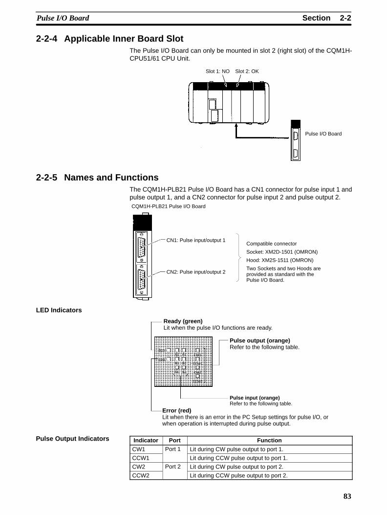
2-2-4 Applicable Inner Board SlotThe Pulse I/O Board can only be mounted in slot 2 (right slot) of the CQM1H-CPU51/61 CPU Unit.
Slot 1: NO Slot 2: OK
Pulse I/O Board
2-2-5 Names and FunctionsThe CQM1H-PLB21 Pulse I/O Board has a CN1 connector for pulse input 1 andpulse output 1, and a CN2 connector for pulse input 2 and pulse output 2.CQM1H-PLB21 Pulse I/O Board
CN1: Pulse input/output 1
CN2: Pulse input/output 2
Compatible connector
Socket: XM2D-1501 (OMRON)
Hood: XM2S-1511 (OMRON)
Two Sockets and two Hoods areprovided as standard with thePulse I/O Board.
LED Indicators
Ready (green)Lit when the pulse I/O functions are ready.
Error (red)Lit when there is an error in the PC Setup settings for pulse I/O, orwhen operation is interrupted during pulse output.
Pulse output (orange)Refer to the following table.
Pulse input (orange)Refer to the following table.
RDY
ERR
A1 A2
B1 B2
S1 S2
CW1
CCW1
CW2
CCW2
Indicator Port Function
CW1 Port 1 Lit during CW pulse output to port 1.
CCW1 Lit during CCW pulse output to port 1.
CW2 Port 2 Lit during CW pulse output to port 2.
CCW2 Lit during CCW pulse output to port 2.
Pulse Output Indicators

2-2SectionPulse I/O Board
84
Port 1 Port 2 Function
A1 A2 Lit when the phase-A pulse input is ON at the port.
B1 B2 Lit when the phase-B pulse input is ON at the port.
Z1 Z2 Lit when the phase-Z pulse input is ON at the port.
2-2-6 Specifications
High-speed Counter Specifications
Instructions
Instruction Control Meaning(@)CTBL(63) Range comparison table registration +
comparison startRegisters range comparison table and startscomparison.
Target value table registration + comparisonstart
Registers target value table and startscomparison.
Range comparison table registration Registers range comparison table.
Target value table registration Registers target value table.
(@)INI(61) Comparison start Starts comparison using registeredcomparison table.
Comparison stop Stops comparison.
PV change Changes PV of high-speed counter.
(@)PRV(62) PV read Reads PV of high-speed counter.( ) ( )
Status read Reads status of high-speed counter.
Range comparison result read Reads range comparison result.
(@)INT(89) Masking all interrupts asking all interrupts, such as input interrupts,interval timer interrupts, and high-speedcounter interrupts.
Clearing interrupt masks Clears masks from interrupts.
Bits for Slot 2 of Inner Board when Using Pulse I/O Board
Word Bits Name Function
IR 232 00 to 15 Port 1 PV word (rightmost fourdigits)
The PV of the high-speed counter for each port ofthe Pulse I/O Board is stored as an 8-digit BCD
l ft h lIR 233 00 to 15 PV word (leftmost fourdigits)
gvalue after each cycle.
IR 234 00 to 15 Port 2 PV word (rightmost fourdigits)
IR 235 00 to 15 PV word (leftmost fourdigits)
SR Area Bits
Word Bit Name FunctionSR 252 01 High-speed Counter 1
Reset Bit (port 1)Phase Z and software reset
0: Counter not reset on phase Z 1: Counter reset on phase Z
02 High-speed Counter 2Reset Bit (port 2)
Software reset only0: Counter not reset0→1: Counter reset
Pulse Input Indicators
Relevant Flags andControl Bits for PulseInputs
2-2SectionPulse I/O Board
85
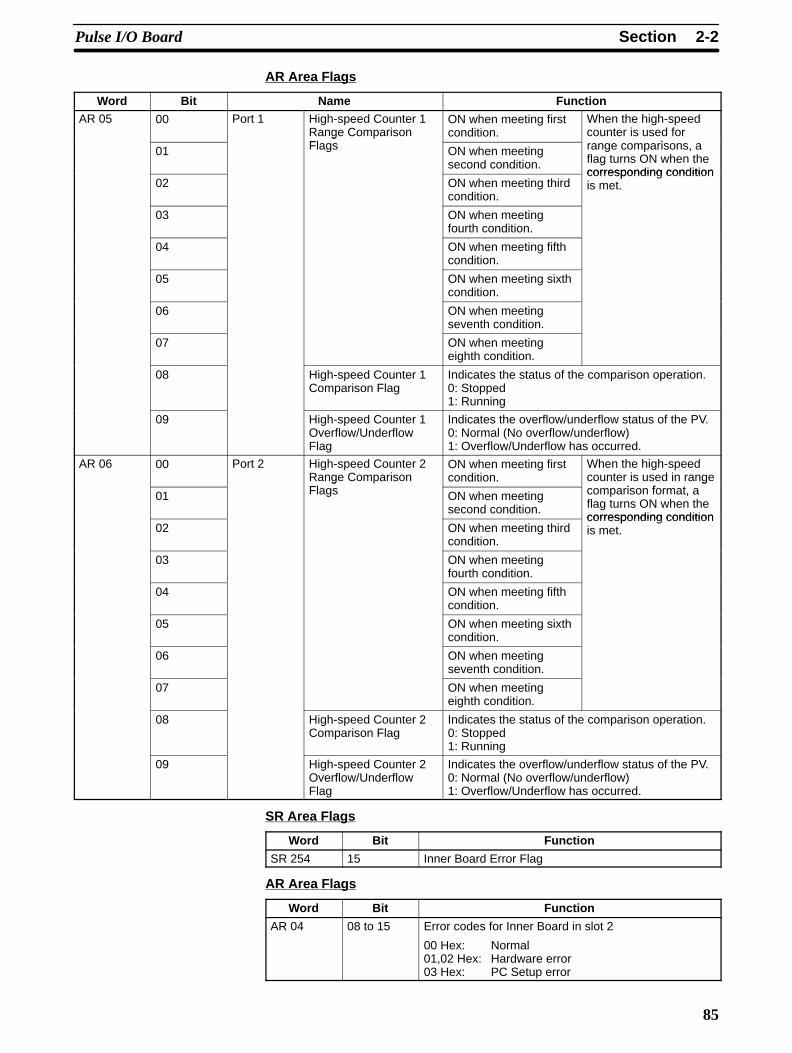
AR Area Flags
Word Bit Name FunctionAR 05 00 Port 1 High-speed Counter 1
Range ComparisonFl
ON when meeting firstcondition.
When the high-speedcounter is used for
i01
gFlags ON when meeting
second condition.
range comparisons, aflag turns ON when thecorresponding condition
02 ON when meeting thirdcondition.
corresponding conditionis met.
03 ON when meetingfourth condition.
04 ON when meeting fifthcondition.
05 ON when meeting sixthcondition.
06 ON when meetingseventh condition.
07 ON when meetingeighth condition.
08 High-speed Counter 1Comparison Flag
Indicates the status of the comparison operation.0: Stopped1: Running
09 High-speed Counter 1Overflow/UnderflowFlag
Indicates the overflow/underflow status of the PV.0: Normal (No overflow/underflow)1: Overflow/Underflow has occurred.
AR 06 00 Port 2 High-speed Counter 2Range ComparisonFl
ON when meeting firstcondition.
When the high-speedcounter is used in range
i f t01
gFlags ON when meeting
second condition.
gcomparison format, aflag turns ON when thecorresponding condition
02 ON when meeting thirdcondition.
corresponding conditionis met.
03 ON when meetingfourth condition.
04 ON when meeting fifthcondition.
05 ON when meeting sixthcondition.
06 ON when meetingseventh condition.
07 ON when meetingeighth condition.
08 High-speed Counter 2Comparison Flag
Indicates the status of the comparison operation.0: Stopped1: Running
09 High-speed Counter 2Overflow/UnderflowFlag
Indicates the overflow/underflow status of the PV.0: Normal (No overflow/underflow)1: Overflow/Underflow has occurred.
SR Area Flags
Word Bit Function
SR 254 15 Inner Board Error Flag
AR Area Flags
Word Bit Function
AR 04 08 to 15 Error codes for Inner Board in slot 2
00 Hex: Normal01,02 Hex: Hardware error03 Hex: PC Setup error
2-2SectionPulse I/O Board
86
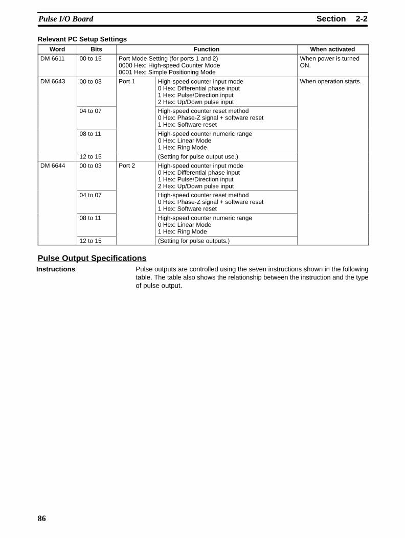
Relevant PC Setup SettingsWord Bits Function When activated
DM 6611 00 to 15 Port Mode Setting (for ports 1 and 2)0000 Hex: High-speed Counter Mode0001 Hex: Simple Positioning Mode
When power is turnedON.
DM 6643 00 to 03 Port 1 High-speed counter input mode0 Hex: Differential phase input1 Hex: Pulse/Direction input2 Hex: Up/Down pulse input
When operation starts.
04 to 07 High-speed counter reset method0 Hex: Phase-Z signal + software reset1 Hex: Software reset
08 to 11 High-speed counter numeric range 0 Hex: Linear Mode1 Hex: Ring Mode
12 to 15 (Setting for pulse output use.)
DM 6644 00 to 03 Port 2 High-speed counter input mode0 Hex: Differential phase input1 Hex: Pulse/Direction input2 Hex: Up/Down pulse input
04 to 07 High-speed counter reset method0 Hex: Phase-Z signal + software reset1 Hex: Software reset
08 to 11 High-speed counter numeric range 0 Hex: Linear Mode1 Hex: Ring Mode
12 to 15 (Setting for pulse outputs.)
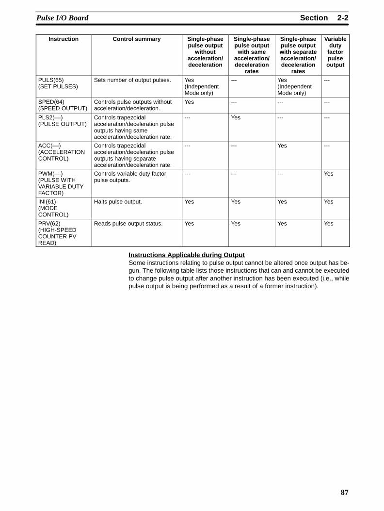
Pulse Output SpecificationsPulse outputs are controlled using the seven instructions shown in the followingtable. The table also shows the relationship between the instruction and the typeof pulse output.
Instructions
2-2SectionPulse I/O Board
87
Instruction Control summary Single-phasepulse output
withoutacceleration/deceleration
Single-phasepulse output
with sameacceleration/deceleration
rates
Single-phasepulse outputwith separateacceleration/deceleration
rates
Variableduty
factorpulseoutput
PULS(65) (SET PULSES)
Sets number of output pulses. Yes(IndependentMode only)
--- Yes(IndependentMode only)
---
SPED(64) (SPEED OUTPUT)
Controls pulse outputs withoutacceleration/deceleration.
Yes --- --- ---
PLS2(––) (PULSE OUTPUT)
Controls trapezoidalacceleration/deceleration pulseoutputs having sameacceleration/deceleration rate.
--- Yes --- ---
ACC(––)(ACCELERATIONCONTROL)
Controls trapezoidalacceleration/deceleration pulseoutputs having separateacceleration/deceleration rate.
--- --- Yes ---
PWM(––) (PULSE WITHVARIABLE DUTYFACTOR)
Controls variable duty factorpulse outputs.
--- --- --- Yes
INI(61) (MODECONTROL)
Halts pulse output. Yes Yes Yes Yes
PRV(62) (HIGH-SPEEDCOUNTER PVREAD)
Reads pulse output status. Yes Yes Yes Yes
Instructions Applicable during OutputSome instructions relating to pulse output cannot be altered once output has be-gun. The following table lists those instructions that can and cannot be executedto change pulse output after another instruction has been executed (i.e., whilepulse output is being performed as a result of a former instruction).

2-2SectionPulse I/O Board
88
Instructionth t t t d
Instruction used to change pulse outputs uc othat startedpulse output
SPED(Inde-pen-dent)
SPED(Contin-uous)
PULS (0 or 1:Pulse
setting)
PULS (2 or 3:pulseaccel-
eration/decel-erationsetting)
PULS(4 or 5:
Nopulse
setting)
PLS2 ACCMode 0(Accel-eration+ Inde-
pen-dent)
ACCMode 1(Accel-eration+ Con-tinu-ous)
ACCMode 2(Decel-eration+ Inde-
pen-dent)
ACCMode 3(Decel-eration+ Con-tinu-ous)
PWM
SPED(64)(IndependentMode
Enabled --- --- --- --- --- Enabled --- Enabled --- ---
SPED(64)(ContinuousMode)
Enabled Enabled Enabled Enabled --- --- --- Enabled --- Enabled ---
PULS(65) 0,1(Pulsesetting)
Enabled Enabled Enabled Enabled Enabled Enabled --- Enabled Enabled Enabled ---
PULS(65) 2,3(Pulseacceleration/decelerationsetting)
Enabled Enabled Enabled Enabled Enabled Enabled Enabled Enabled Enabled Enabled ---
PULS(65) 3,4(No pulsesetting)
--- Enabled Enabled Enabled Enabled Enabled --- Enabled --- Enabled ---
PLS2(––) --- --- --- --- --- --- --- --- Enabledwhenstopped
--- ---
ACC(––)Mode 0 (Ac -celeration +Independent)
--- --- --- --- --- --- --- --- Enabled --- ---
ACC(––)Mode 1(Acceleration+Continuous)
--- Enabledforconstantspeed
Enabled(seenote)
Enabled(seenote)
--- --- --- Enabledforconstantspeed
--- Enabled ---
ACC(––)Mode 2(Deceleration+Independent)
Enabledforconstantspeed
--- --- --- --- --- --- --- Enabled --- ---
ACC(––)Mode 0(Deceleration+Continuous)
--- Enabledforconstantspeed
Enabled(seenote)
Enabled(seenote)
Enabled(seenote)
--- --- Enabledforconstantspeed
--- Enabled ---
PWM(––) --- --- --- --- --- --- --- --- --- --- Enabled
Note The number of pulses can be changed, but the direction cannot be changed.
Bits for Slot 2 of Inner Board when Using Pulse I/O Board
Word Bits Name Function
IR 236 00 to 15 Port 1 PV word (rightmost four digits) The PV of the pulse output associated with each portf h P l I/O B d i d 8 di i BCDIR 237 00 to 15 PV word (leftmost four digits) of the Pulse I/O Board is stored as an 8-digit BCD
after each cycleIR 238 00 to 15 Port 2 PV word (rightmost four digits)
after each cycle.When pulse output is not used, these bits can be
IR 239 00 to 15 PV word (leftmost four digits)When ulse out ut is not used, these bits can beused as internal auxiliary bits.
Relevant Flags andControl Bits (for PulseOutput)
2-2SectionPulse I/O Board
89
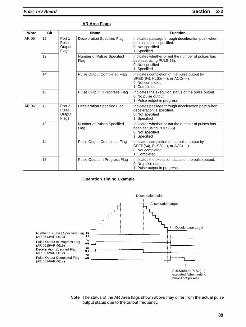
AR Area Flags
Word Bit Name Function
AR 05 12 Port 1PulseOutputFlags
Deceleration Specified Flag Indicates passage through deceleration point whendeceleration is specified.0: Not specified1: Specified
13
ags
Number of Pulses SpecifiedFlag
Indicates whether or not the number of pulses hasbeen set using PULS(65).0: Not specified1: Specified
14 Pulse Output Completed Flag Indicates completion of the pulse output bySPED(64), PLS2(––), or ACC(––).0: Not completed1: Completed
15 Pulse Output In Progress Flag Indicates the execution status of the pulse output.0: No pulse output1: Pulse output in progress
AR 06 12 Port 2PulseOutputFlags
Deceleration Specified Flag Indicates passage through deceleration point whendeceleration is specified.0: Not specified1: Specified
13
ags
Number of Pulses SpecifiedFlag
Indicates whether or not the number of pulses hasbeen set using PULS(65).0: Not specified1: Specified
14 Pulse Output Completed Flag Indicates completion of the pulse output bySPED(64), PLS2(––), or ACC(––).0: Not completed1: Completed
15 Pulse Output In Progress Flag Indicates the execution status of the pulse output.0: No pulse output1: Pulse output in progress
Operation Timing Example
Deceleration point
Acceleration target
Deceleration target
PULS(65) or PLS2(––)executed (when settingnumber of pulses).
Number of Pulses Specified Flag(AR 0513/AR 0613)
Pulse Output In Progress Flag(AR 0515/AR 0615)Deceleration Specified Flag(AR 0512/AR 0612)Pulse Output Completed Flag(AR 0514/AR 0614)
Note The status of the AR Area flags shown above may differ from the actual pulseoutput status due to the output frequency.
2-2SectionPulse I/O Board
90
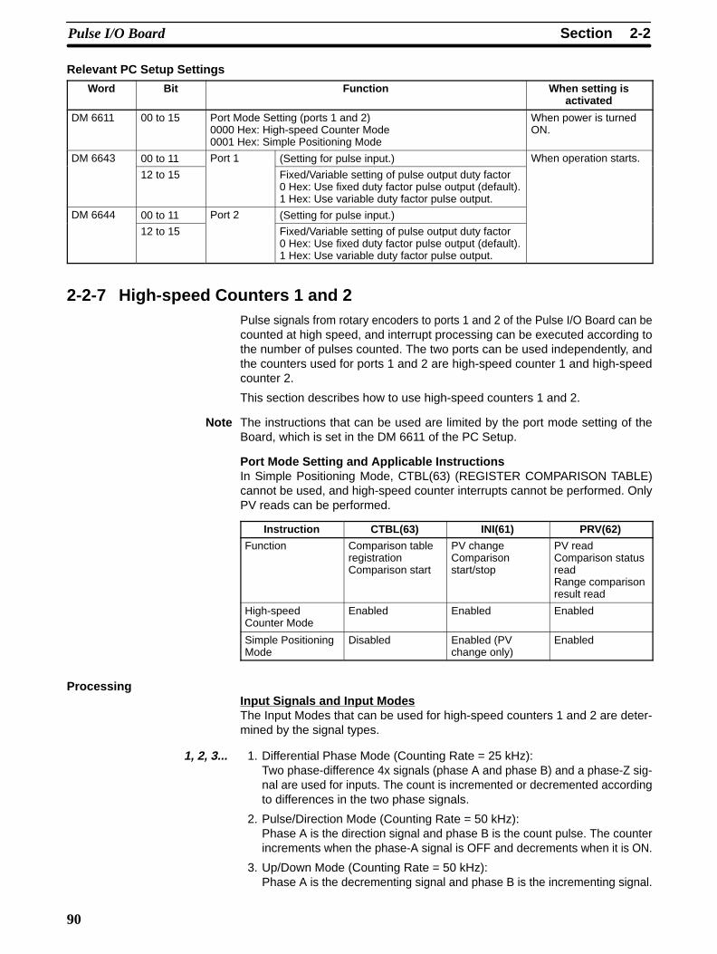
Relevant PC Setup Settings
Word Bit Function When setting isactivated
DM 6611 00 to 15 Port Mode Setting (ports 1 and 2)0000 Hex: High-speed Counter Mode0001 Hex: Simple Positioning Mode
When power is turnedON.
DM 6643 00 to 11 Port 1 (Setting for pulse input.) When operation starts.
12 to 15 Fixed/Variable setting of pulse output duty factor0 Hex: Use fixed duty factor pulse output (default).1 Hex: Use variable duty factor pulse output.
DM 6644 00 to 11 Port 2 (Setting for pulse input.)
12 to 15 Fixed/Variable setting of pulse output duty factor0 Hex: Use fixed duty factor pulse output (default).1 Hex: Use variable duty factor pulse output.
2-2-7 High-speed Counters 1 and 2Pulse signals from rotary encoders to ports 1 and 2 of the Pulse I/O Board can becounted at high speed, and interrupt processing can be executed according tothe number of pulses counted. The two ports can be used independently, andthe counters used for ports 1 and 2 are high-speed counter 1 and high-speedcounter 2.
This section describes how to use high-speed counters 1 and 2.
Note The instructions that can be used are limited by the port mode setting of theBoard, which is set in the DM 6611 of the PC Setup.
Port Mode Setting and Applicable InstructionsIn Simple Positioning Mode, CTBL(63) (REGISTER COMPARISON TABLE)cannot be used, and high-speed counter interrupts cannot be performed. OnlyPV reads can be performed.
Instruction CTBL(63) INI(61) PRV(62)
Function Comparison tableregistrationComparison start
PV changeComparisonstart/stop
PV readComparison statusreadRange comparisonresult read
High-speedCounter Mode
Enabled Enabled Enabled
Simple PositioningMode
Disabled Enabled (PVchange only)
Enabled
ProcessingInput Signals and Input ModesThe Input Modes that can be used for high-speed counters 1 and 2 are deter-mined by the signal types.
1, 2, 3... 1. Differential Phase Mode (Counting Rate = 25 kHz):Two phase-difference 4x signals (phase A and phase B) and a phase-Z sig-nal are used for inputs. The count is incremented or decremented accordingto differences in the two phase signals.
2. Pulse/Direction Mode (Counting Rate = 50 kHz):Phase A is the direction signal and phase B is the count pulse. The counterincrements when the phase-A signal is OFF and decrements when it is ON.
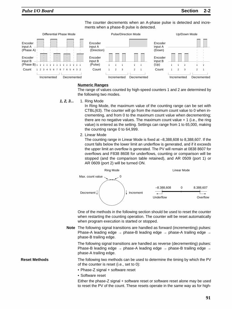
3. Up/Down Mode (Counting Rate = 50 kHz):Phase A is the decrementing signal and phase B is the incrementing signal.
2-2SectionPulse I/O Board
91
The counter decrements when an A-phase pulse is detected and incre-ments when a phase-B pulse is detected.
1 2 3 4 5 6 7 8 7 6 5 4 3 2
Encoderinput A(Phase A)
Encoderinput B(Phase B)
Differential Phase Mode
Count
Incremented Decremented
1 2
Encoderinput A (Direction)
Encoderinput B (Pulse)
Pulse/Direction Mode
Count
Incremented Decremented
Encoderinput A(Down)
Encoderinput B(Up)
Up/Down Mode
Count3 2 1 1 2
Incremented Decremented
3 2 1
Numeric RangesThe range of values counted by high-speed counters 1 and 2 are determined bythe following two modes.
1, 2, 3... 1. Ring ModeIn Ring Mode, the maximum value of the counting range can be set withCTBL(63). The counter will go from the maximum count value to 0 when in-crementing, and from 0 to the maximum count value when decrementing;there are no negative values. The maximum count value + 1 (i.e., the ringvalue) is entered as the setting. Settings can range from 1 to 65,000, makingthe counting range 0 to 64,999.
2. Linear ModeThe counting range in Linear Mode is fixed at –8,388,608 to 8,388,607. If thecount falls below the lower limit an underflow is generated, and if it exceedsthe upper limit an overflow is generated. The PV will remain at 0838 8607 foroverflows and F838 8608 for underflows, counting or comparison will bestopped (and the comparison table retained), and AR 0509 (port 1) orAR 0609 (port 2) will be turned ON.
Ring Mode
0Max. count value
Decrement Increment
Linear Mode
0–8.388,608 8.388,607
Underflow Overflow
One of the methods in the following section should be used to reset the counterwhen restarting the counting operation. The counter will be reset automaticallywhen program execution is started or stopped.
Note The following signal transitions are handled as forward (incrementing) pulses:Phase-A leading edge → phase-B leading edge → phase-A trailing edge →phase-B trailing edge.
The following signal transitions are handled as reverse (decrementing) pulses:Phase-B leading edge → phase-A leading edge → phase-B trailing edge →phase-A trailing edge.
The following two methods can be used to determine the timing by which the PVof the counter is reset (i.e., set to 0):• Phase-Z signal + software reset• Software resetEither the phase-Z signal + software reset or software reset alone may be usedto reset the PV of the count. These resets operate in the same way as for high-
Reset Methods
2-2SectionPulse I/O Board
92
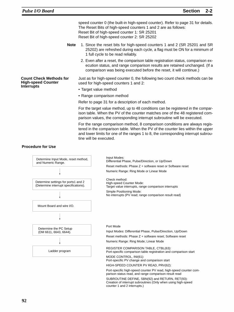
speed counter 0 (the built-in high-speed counter). Refer to page 31 for details.The Reset Bits of high-speed counters 1 and 2 are as follows:Reset Bit of high-speed counter 1: SR 25201Reset Bit of high-speed counter 2: SR 25202
Note 1. Since the reset bits for high-speed counters 1 and 2 (SR 25201 and SR25202) are refreshed during each cycle, a flag must be ON for a minimum of1 full cycle to be read reliably.
2. Even after a reset, the comparison table registration status, comparison ex-ecution status, and range comparison results are retained unchanged. (If acomparison was being executed before the reset, it will continue.)
Just as for high-speed counter 0, the following two count check methods can beused for high-speed counters 1 and 2:
• Target value method
• Range comparison method
Refer to page 31 for a description of each method.
For the target value method, up to 48 conditions can be registered in the compar-ison table. When the PV of the counter matches one of the 48 registered com-parison values, the corresponding interrupt subroutine will be executed.
For the range comparison method, 8 comparison conditions are always regis-tered in the comparison table. When the PV of the counter lies within the upperand lower limits for one of the ranges 1 to 8, the corresponding interrupt subrou-tine will be executed.
Procedure for Use
Determine Input Mode, reset method,and Numeric Range.
Mount Board and wire I/O.
Input Modes: Differential Phase, Pulse/Direction, or Up/Down
Reset methods: Phase Z + software reset or Software reset
Numeric Range: Ring Mode or Linear Mode
Determine settings for ports1 and 2(Determine interrupt specifications).
Determine the PC Setup(DM 6611, 6643, 6644).
Ladder program
Port Mode
Input Modes: Differential Phase, Pulse/Direction, Up/Down
Reset methods: Phase Z + software reset; Software reset
Numeric Range: Ring Mode; Linear Mode
REGISTER COMPARISON TABLE, CTBL(63): Port-specific comparison table registration and comparison start
MODE CONTROL, INI(61): Port-specific PV change and comparison start
HIGH-SPEED COUNTER PV READ, PRV(62):
Port-specific high-speed counter PV read, high-speed counter com-parison status read, and range comparison result read
SUBROUTINE DEFINE, SBN(92) and RETURN, RET(93): Creation of interrupt subroutines (Only when using high-speedcounter 1 and 2 interrupts.)
Check method: High-speed Counter Mode:Target value interrupts, range comparison interrupts
Simple Positioning Mode: No interrupts (PV read; range comparison result read)
Count Check Methods forHigh-speed CounterInterrupts
2-2SectionPulse I/O Board
93
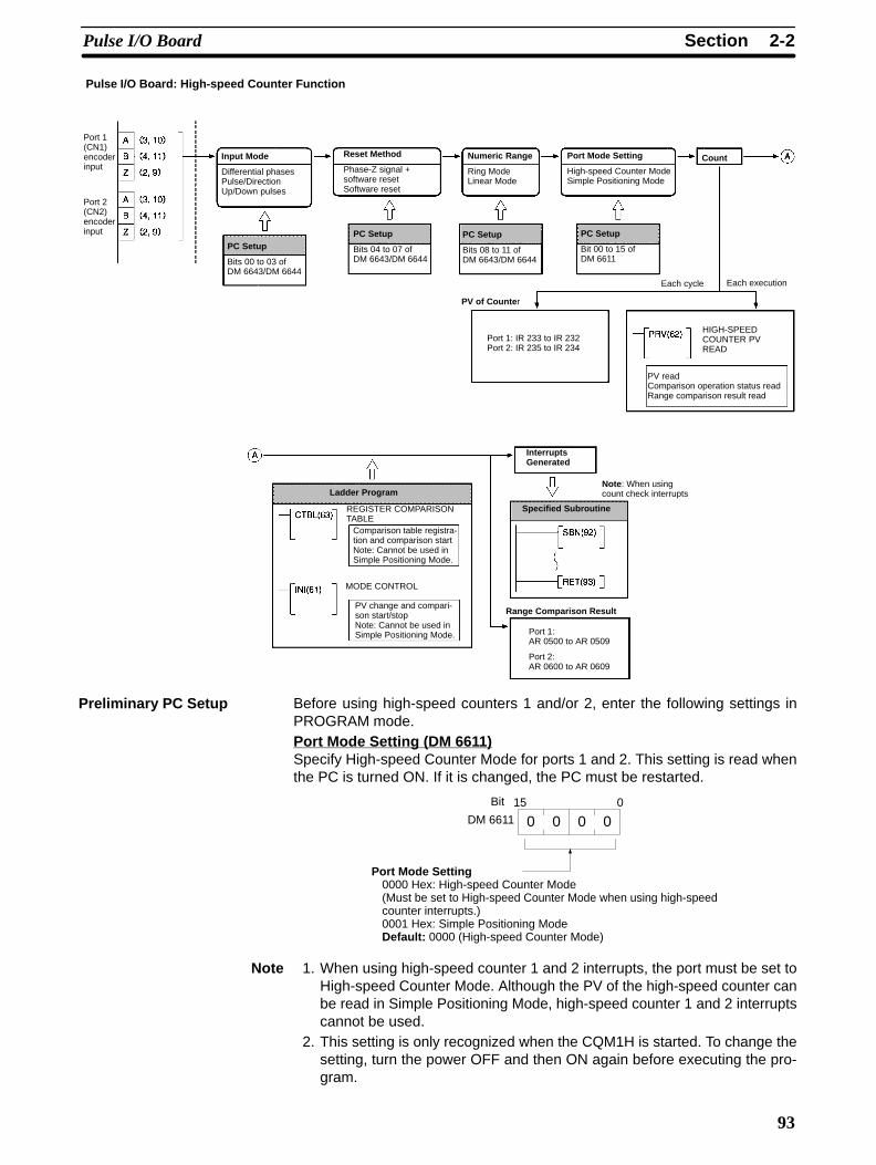
Pulse I/O Board: High-speed Counter Function
Input Mode
Differential phases Pulse/Direction Up/Down pulses
Port Mode Setting
High-speed Counter ModeSimple Positioning Mode
Numeric Range
Ring ModeLinear Mode
Port 1(CN1)encoderinput
Port 2(CN2)encoderinput
Reset Method
Phase-Z signal +software resetSoftware reset
InterruptsGenerated
Port 1: AR 0500 to AR 0509
Port 2: AR 0600 to AR 0609
Range Comparison Result
Each cycle
PV of Counte r
Port 1: IR 233 to IR 232Port 2: IR 235 to IR 234
Each execution
HIGH-SPEEDCOUNTER PVREAD
PV readComparison operation status readRange comparison result read
Note : When usingcount check interrupts
REGISTER COMPARISONTABLE
Comparison table registra-tion and comparison start Note: Cannot be used inSimple Positioning Mode.
MODE CONTROL
PV change and compari-son start/stopNote: Cannot be used inSimple Positioning Mode.
Count
PC Setup
Bits 00 to 03 ofDM 6643/DM 6644
PC Setup
Bits 04 to 07 ofDM 6643/DM 6644
PC Setup
Bits 08 to 11 ofDM 6643/DM 6644
PC Setup
Bit 00 to 15 ofDM 6611
Specified Subroutine
Ladder Program
Before using high-speed counters 1 and/or 2, enter the following settings inPROGRAM mode.Port Mode Setting (DM 6611)Specify High-speed Counter Mode for ports 1 and 2. This setting is read whenthe PC is turned ON. If it is changed, the PC must be restarted.
15 0
DM 6611 0 0 0 0Bit
Port Mode Setting0000 Hex: High-speed Counter Mode(Must be set to High-speed Counter Mode when using high-speedcounter interrupts.)0001 Hex: Simple Positioning ModeDefault: 0000 (High-speed Counter Mode)
Note 1. When using high-speed counter 1 and 2 interrupts, the port must be set toHigh-speed Counter Mode. Although the PV of the high-speed counter canbe read in Simple Positioning Mode, high-speed counter 1 and 2 interruptscannot be used.
2. This setting is only recognized when the CQM1H is started. To change thesetting, turn the power OFF and then ON again before executing the pro-gram.
Preliminary PC Setup
2-2SectionPulse I/O Board
94
3. If DM 6611 is used to set ports 1 and 2 to Simple Positioning Mode, it is pos-sible to use the BCMP(68) instruction to check the contents of the PV wordsof high-speed counters 1 and 2 (IR 232 to IR 235) and use this information inplace of high-speed counter 1 and 2 interrupts. However, the PV obtainedusing this method may vary slightly from the actual PV.
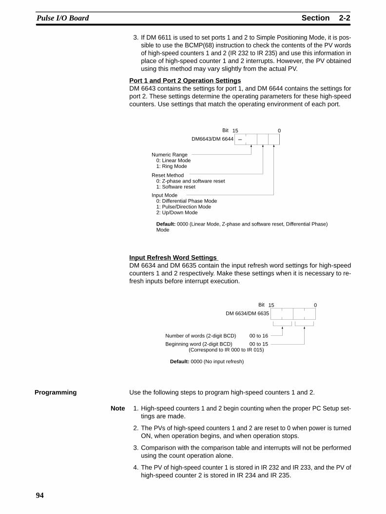
Port 1 and Port 2 Operation SettingsDM 6643 contains the settings for port 1, and DM 6644 contains the settings forport 2. These settings determine the operating parameters for these high-speedcounters. Use settings that match the operating environment of each port.
Numeric Range0: Linear Mode1: Ring Mode
15 0
DM6643/DM 6644
Bit
–
Reset Method0: Z-phase and software reset1: Software reset
Input Mode0: Differential Phase Mode1: Pulse/Direction Mode2: Up/Down Mode
Default: 0000 (Linear Mode, Z-phase and software reset, Differential Phase)Mode
Input Refresh Word Settings DM 6634 and DM 6635 contain the input refresh word settings for high-speedcounters 1 and 2 respectively. Make these settings when it is necessary to re-fresh inputs before interrupt execution.
15 0
DM 6634/DM 6635
Bit
Number of words (2-digit BCD) 00 to 16
Beginning word (2-digit BCD) 00 to 15(Correspond to IR 000 to IR 015)
Default: 0000 (No input refresh)
Use the following steps to program high-speed counters 1 and 2.
Note 1. High-speed counters 1 and 2 begin counting when the proper PC Setup set-tings are made.
2. The PVs of high-speed counters 1 and 2 are reset to 0 when power is turnedON, when operation begins, and when operation stops.
3. Comparison with the comparison table and interrupts will not be performedusing the count operation alone.
4. The PV of high-speed counter 1 is stored in IR 232 and IR 233, and the PV ofhigh-speed counter 2 is stored in IR 234 and IR 235.
Programming

2-2SectionPulse I/O Board
95
Starting and Stopping Comparison
1, 2, 3... 1. Use CTBL(63) to save the comparison table in the CQM1H and begin com-parisons.
(@)CTBL(63)
P
C
TB
P: Port001: Port 1002: Port 2
C: Mode000: Target value table registered and comparison begun001: Range table registered and comparison begun002: Target table registered only003: Range table registered only
TB: Beginning word of comparison table
If C is set to 000, then comparisons will be made using the target value meth-od; if 001, they will be made using the range comparison method. In bothcases the comparisons will begin after the comparison table is registered.While comparisons are being performed, high-speed counter 1 and 2 inter-rupts will be executed according to the comparison table. Refer to the ex-planation of CTBL(63) in Section 5 Instruction Set for details on the contentsof the comparison tables that are saved.
Note Although setting the value of C to 002 registers a target value com-parison table, and setting C to 003 registers a range comparisontable, comparison does not start automatically. In these cases,INI(61) must be used to start the comparison operation.
2. To stop comparisons, execute INI(61) as shown below. Specify port 1 or 2 inP (P=001 or 002).
(@)INI(61)
P
001
000
P: Port001: Port 1002: Port 2
Note 1. To restart comparisons, set the first operand to the port number, and the sec-ond operand to “000” (execute comparison), and execute the INI(61)instruction.
2. A table that has been registered will be retained in the CQM1H during opera-tion (i.e., during program execution) until a new table is registered.
Reading the PV of High-speed Counters 1 and 2The following two methods can be used to read the PVs of high-speed counters1 and 2:
• Reading the PV from memory
• Using PRV(62)
Reading the PV from MemoryThe PVs of high-speed counters 1 and 4 are stored in the corresponding dataarea words in the following way.
Leftmost four digits Rightmost four digits Linear Mode Ring Mode
IR 233 IR 232 F8388608 to 08388607(–8,388,608 to 8,388,607)(The leftmost digit becomes F when the number isnegative.)
00000000 to 00064999Port 1:
IR 235 IR 234Port 2:
Note These words are refreshed only once every cycle, so they may differ from theactual PV.
2-2SectionPulse I/O Board
96
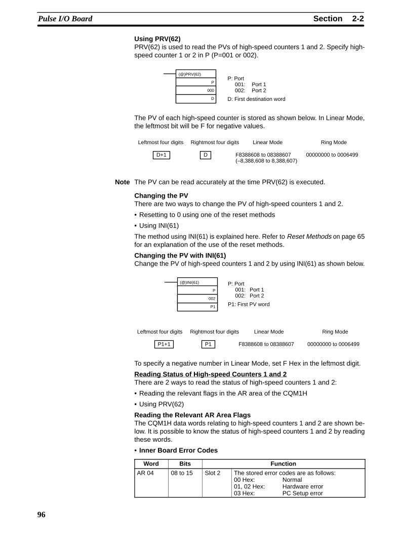
Using PRV(62)PRV(62) is used to read the PVs of high-speed counters 1 and 2. Specify high-speed counter 1 or 2 in P (P=001 or 002).
(@)PRV(62)
P
000
D
P: Port001: Port 1002: Port 2
D: First destination word
The PV of each high-speed counter is stored as shown below. In Linear Mode,the leftmost bit will be F for negative values.
Leftmost four digits Rightmost four digits Linear Mode Ring Mode
D+1 D F8388608 to 08388607(–8,388,608 to 8,388,607)
00000000 to 0006499
Note The PV can be read accurately at the time PRV(62) is executed.
Changing the PVThere are two ways to change the PV of high-speed counters 1 and 2.
• Resetting to 0 using one of the reset methods
• Using INI(61)
The method using INI(61) is explained here. Refer to Reset Methods on page 65for an explanation of the use of the reset methods.
Changing the PV with INI(61)Change the PV of high-speed counters 1 and 2 by using INI(61) as shown below.
(@)INI(61)
P
002
P1
P: Port001: Port 1002: Port 2
P1: First PV word
Leftmost four digits Rightmost four digits Linear Mode Ring Mode
P1+1 P1 F8388608 to 08388607 00000000 to 0006499
To specify a negative number in Linear Mode, set F Hex in the leftmost digit.
Reading Status of High-speed Counters 1 and 2There are 2 ways to read the status of high-speed counters 1 and 2:
• Reading the relevant flags in the AR area of the CQM1H
• Using PRV(62)
Reading the Relevant AR Area FlagsThe CQM1H data words relating to high-speed counters 1 and 2 are shown be-low. It is possible to know the status of high-speed counters 1 and 2 by readingthese words.
• Inner Board Error Codes
Word Bits Function
AR 04 08 to 15 Slot 2 The stored error codes are as follows:00 Hex: Normal01, 02 Hex: Hardware error03 Hex: PC Setup error

2-2SectionPulse I/O Board
97
• Operating Status
Word Bit Name Function
Counter 1 Counter 2AR 05 AR 06 00 High-speed Counter
Range ComparisonFl
ON when meeting firstcondition.
When the high-speedcounter is used in range
i f t bit01
gFlags ON when meeting
second condition.
gcomparison format, a bitturns ON when thecorresponding condition
02 ON when meeting thirdcondition.
corresponding conditionis met.
03 ON when meeting fourthcondition.
04 ON when meeting fifthcondition.
05 ON when meeting sixthcondition.
06 ON when meetingseventh condition.
07 ON when meeting eighthcondition.
08 High-speed CounterComparison Flag
Indicates the status of the comparison operation.0: Stopped1: Running
09 High-speed CounterOverflow/Underflow Flag
Indicates the overflow/underflow status of the PV.0: Normal (No overflow/underflow)1: Overflow/Underflow has occurred
Using PRV(62)The status of high-speed counters 1 and 2 can also be determined by executingPRV(62). Specify high-speed counter 1 or 2 (P=001 or 002) and the destinationword D. The status information will be written to bits 00 and 01 of D. Bits 02 to 15will be set to 0.
(@)PRV(62)
P
000
D
P: Port001: Port 1002: Port 2
D: Destination word
The status of the specified high-speed counter is stored in bits 00 and 01 of P1,as shown in the following table.
Bit Function
00 Comparison Operation Flag (0: Stopped; 1: Running)
01 High-speed Counter 1 and 2 PV Overflow/Underflow Flag (0: Normal; 1:Underflow or overflow occurred)
Bits 04 to 07 indicate the pulse output status; all other bits are 0.
This example shows a program that outputs standard pulses from port 1 whilecounting those pulses with high-speed counter 1. The high-speed counter oper-ates in Up/Down Mode, with the pulse output’s CW pulses incrementing thecounter (B-phase input) and the CCW pulses decrementing the counter (A-phase input). Before executing the program, set the PC Setup as follows andrestart the PC to enable the DM 6611 settings.
DM 6611: 0000 (High-speed Counter Mode).
DM 6643: 0002 (Port 1: Fixed duty factor pulse output, Linear Mode, Z-phasesignal with software reset, and Up/Down Mode).
Other PC Setup settings use the default settings. (Inputs are not refreshed be-fore interrupt processing.)
Example

2-2SectionPulse I/O Board
98
In addition, the following data is stored for the comparison table:
DM 0000: 0003 — Number of target values: 3
DM 0001: 2500 — Target value 1: 2,500DM 0002: 0000
DM 0003: 0100 — Comparison 1 interrupt processing routine No.: 100
DM 0004: 7500 — Target value 2: 7,500DM 0005: 0000
DM 0006: 0101 — Comparison 2 interrupt processing routine No.: 101
DM 0007: 0000 — Target value 3: 10,000DM 0008: 0001
DM 0009: 0102 — Comparison 3 interrupt processing routine No.: 102
00000
SBN(92) 100
RET(93)
@ACC(––)
001
003
DM 0012
SPED(64)
001
001
#0000
25313 (Always ON)
SBN(92) 102
RET(93)
25313 (Always ON)
@CTBL(63)
001
000
DM 0000
@PULS(65)
001
004
000
Specifies port 1, saves the comparisontable in target value format, and beginscomparing.
Sets CW pulses for port 1. (Number ofpulses not set.)
Pulse output from port 1 is stopped by set-ting the frequency to 0.
@SPED(64)
001
001
#0001
Begins continuous pulse output from port1 at frequency unit of 10 Hz.
@ACC(––)
001
001
DM 0010
ACC(––) mode 1 accelerates the fre-quency to 25 kHz at about 500 Hz/4 ms.
DM 0010: 0050 500 Hz acc./4 ms.DM 0011: 2500 Target value 25 kHz.
25313 (Always ON)
10000
RET(93)
SBN(92) 101
Turns ON IR 10000.
ACC(––) mode 3 decelerates the fre-quency to 500 Hz at about 500 Hz/4 ms.
DM 0012: 0050 500 Hz acc./4 ms.DM 0013: 0050 Target value: 500 Hz.
2-2SectionPulse I/O Board
99
2-2-8 FunctionsThe pulse output functions of the Pulse I/O Board are given in the following table.
Classification Characteristics Instructions used
Ports 1 and 2 pulseoutput (Fixed dutyfactor)
10 Hz to 50 (20) kHz frequency.Fixed duty factor.Bidirectional output (CW and CCW).Frequency can be changed smoothly.
Set number of pulses: PULS(65)Start pulse output: SPED(64)Change frequency: SPED(64)Stop pulse output: SPED(64)/INI(61)Acceleration/Deceleration at same rate: PLS2(––)Acceleration/Deceleration at separate rates: ACC(––)
Ports 1 and 2 pulseoutput (Variableduty factor)
91.6 Hz, 1.5 kHz, or 5.9 kHz frequency.Duty factor variable between 1% to 99%.Unidirectional output only.
Start pulse output: PWM(––)Stop pulse output: INI(61)
Note When a stepping motor is connected to the pulse output of port 1 or 2, use a max-imum frequency not exceeding 20 kHz.
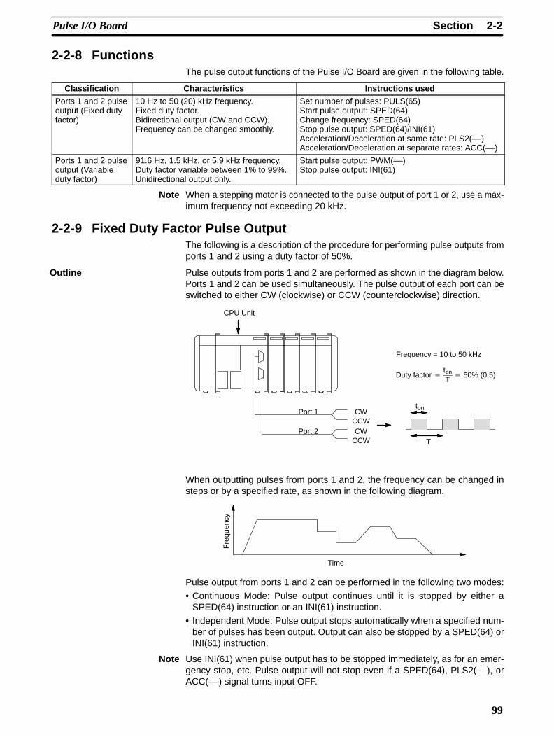
2-2-9 Fixed Duty Factor Pulse OutputThe following is a description of the procedure for performing pulse outputs fromports 1 and 2 using a duty factor of 50%.
Pulse outputs from ports 1 and 2 are performed as shown in the diagram below.Ports 1 and 2 can be used simultaneously. The pulse output of each port can beswitched to either CW (clockwise) or CCW (counterclockwise) direction.
T
ton
Duty factor ton
T 50% (0.5)
CPU Unit
CWCCW
Port 1
CWCCW
Port 2
Frequency = 10 to 50 kHz
When outputting pulses from ports 1 and 2, the frequency can be changed insteps or by a specified rate, as shown in the following diagram.
Fre
quen
cy
Time
Pulse output from ports 1 and 2 can be performed in the following two modes:
• Continuous Mode: Pulse output continues until it is stopped by either aSPED(64) instruction or an INI(61) instruction.
• Independent Mode: Pulse output stops automatically when a specified num-ber of pulses has been output. Output can also be stopped by a SPED(64) orINI(61) instruction.
Note Use INI(61) when pulse output has to be stopped immediately, as for an emer-gency stop, etc. Pulse output will not stop even if a SPED(64), PLS2(––), orACC(––) signal turns input OFF.
Outline
2-2SectionPulse I/O Board
100
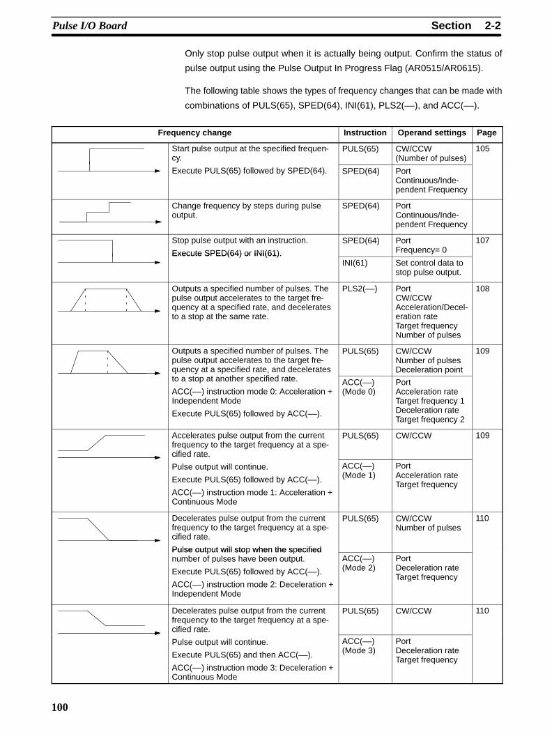
Only stop pulse output when it is actually being output. Confirm the status of
pulse output using the Pulse Output In Progress Flag (AR0515/AR0615).
The following table shows the types of frequency changes that can be made with
combinations of PULS(65), SPED(64), INI(61), PLS2(––), and ACC(––).
Frequency change Instruction Operand settings Page
Start pulse output at the specified frequen-cy.
PULS(65) CW/CCW(Number of pulses)
105y
Execute PULS(65) followed by SPED(64). SPED(64) PortContinuous/Inde-pendent Frequency
Change frequency by steps during pulseoutput.
SPED(64) PortContinuous/Inde-pendent Frequency
Stop pulse output with an instruction.
Execute SPED(64) or INI(61).
SPED(64) PortFrequency= 0
107
Execute SPED(64) or INI(61).INI(61) Set control data to
stop pulse output.
Outputs a specified number of pulses. Thepulse output accelerates to the target fre-quency at a specified rate, and deceleratesto a stop at the same rate.
PLS2(––) PortCW/CCWAcceleration/Decel-eration rateTarget frequencyNumber of pulses
108
Outputs a specified number of pulses. Thepulse output accelerates to the target fre-quency at a specified rate, and deceleratest t t th ifi d t
PULS(65) CW/CCWNumber of pulsesDeceleration point
109
q y ,to a stop at another specified rate.
ACC(––) instruction mode 0: Acceleration +Independent Mode
Execute PULS(65) followed by ACC(––).
ACC(––)(Mode 0)
PortAcceleration rateTarget frequency 1Deceleration rateTarget frequency 2
Accelerates pulse output from the currentfrequency to the target frequency at a spe-cified rate.
PULS(65) CW/CCW 109
cified rate.
Pulse output will continue.
Execute PULS(65) followed by ACC(––).
ACC(––) instruction mode 1: Acceleration +Continuous Mode
ACC(––)(Mode 1)
PortAcceleration rateTarget frequency
Decelerates pulse output from the currentfrequency to the target frequency at a spe-cified rate.
Pulse output will stop when the specified
PULS(65) CW/CCWNumber of pulses
110
Pulse out ut will sto when the s ecifiednumber of pulses have been output.
Execute PULS(65) followed by ACC(––).
ACC(––) instruction mode 2: Deceleration +Independent Mode
ACC(––)(Mode 2)
PortDeceleration rateTarget frequency
Decelerates pulse output from the currentfrequency to the target frequency at a spe-cified rate.
PULS(65) CW/CCW 110
cified rate.
Pulse output will continue.
Execute PULS(65) and then ACC(––).
ACC(––) instruction mode 3: Deceleration +Continuous Mode
ACC(––)(Mode 3)
PortDeceleration rateTarget frequency
2-2SectionPulse I/O Board
101
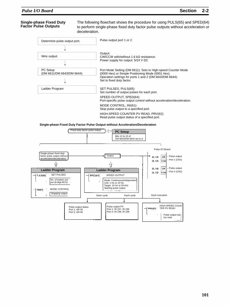
The following flowchart shows the procedure for using PULS(65) and SPED(64)to perform single-phase fixed duty factor pulse outputs without acceleration ordeceleration.
Determine pulse output port.
Wire output.
PC Setup(DM 6611/DM 6643/DM 6644)
Ladder Program
Pulse output port 1 or 2.
Output:CW/CCW with/without 1.6 kΩ resistance.Power supply for output: 5/24 V DC
Port Mode Setting (DM 6611): Sets to High-speed Counter Mode(0000 Hex) or Simple Positioning Mode (0001 Hex).Operation settings for ports 1 and 2 (DM 6643/DM 6644):Set to fixed duty factor.
SET PULSES, PULS(65):Set number of output pulses for each port.
SPEED OUTPUT, SPED(64):Port-specific pulse output control without acceleration/deceleration.
MODE CONTROL, INI(61):Stop pulse output to a specified port.
HIGH-SPEED COUNTER PV READ, PRV(62):Read pulse output status of a specified port.
Fixed duty factor pulse output
Single-phase fixed dutyfactor pulse output withoutacceleration/deceleration
SPEED OUTPUT
No. of pulses out-put (8-digit BCD)
MODE CONTROL
Mode: Continuous/IndependentUnit: 1 Hz or 10 HzTarget: 10 Hz to 50 kHzStarting pulse output
Each cycle Each execution
Pulse output statusPort 1: AR 05Port 2: AR 06
Pulse output PVPort 1: IR 237, IR 236Port 2: IR 239, IR 238
HIGH-SPEED COUN-TER PV READ
Pulse output sta-tus read
Pulse I/O Board
– Pulse output
– Port 1 (CN1)
– Pulse output
– Port 2 (CN2)
Stopping output
Output
Each cycle
Single-phase Fixed Duty Factor Pulse Output without Acceleration/Deceleration
PC SetupBits 12 to 15 ofDM 6643/DM 6644 set to 0.
Ladder ProgramSET PULSES
Ladder Program
Single-phase Fixed DutyFactor Pulse Outputs
2-2SectionPulse I/O Board
102
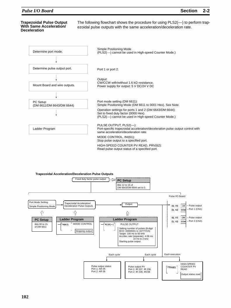
The following flowchart shows the procedure for using PLS2(––) to perform trap-ezoidal pulse outputs with the same acceleration/deceleration rate.
Determine port mode.
Determine pulse output port.
Mount Board and wire outputs.
PC Setup(DM 6611/DM 6643/DM 6644)
Ladder Program
Simple Positioning Mode (PLS2(––) cannot be used in High-speed Counter Mode.)
Port 1 or port 2.
Output:CW/CCW with/without 1.6 kΩ resistance.Power supply for output: 5 V DC/24 V DC
Port mode setting (DM 6611):Simple Positioning Mode (DM 6611 to 0001 Hex). See Note.
Operation settings for ports 1 and 2 (DM 6643/DM 6644):Set to fixed duty factor (0000 Hex).(PLS2(––) cannot be used in High-speed Counter Mode.)
PULSE OUTPUT, PLS2(––):Port-specific trapezoidal acceleration/deceleration pulse output control withsame acceleration/deceleration rate.
MODE CONTROL, INI(61):Stop pulse output to a specified port.
HIGH-SPEED COUNTER PV READ, PRV(62):Read pulse output status of a specified port.
Fixed duty factor pulse output
Trapezoidal Acceleration/Deceleration Pulse Outputs
PULSE OUTPUTMODE CONTROL
Setting number of pulses (8-digitBCD: 00000001 to 16777215)Target: 100 Hz to 50 kHzAcc/dec rate (separate): 4.08 ms
10 Hx to 2 kHzStarting pulse output
Each cycle Each execution
Pulse output statusPort 1: AR 05Port 2: AR 06
Pulse output PVPort 1: IR 237, IR 236Port 2: IR 239, IR238
HIGH-SPEEDCOUNTER PVREAD
Output status read
Pulse I/O Board
– Pulse output
– Port 1 (CN1)
– Pulse output
– Port 2 (CN2)
Port Mode Setting
Simple Positioning Mode
Stopping output
Output
Each cycle
Trapezoidal Acceleration/Deceleration Pulse Outputs
PC SetupBits 12 to 15 ofDM 6643/DM 6644 set to 0.
Ladder ProgramLadder ProgramPC SetupBits 00 to 15of DM 6611
Trapezoidal Pulse OutputWith Same Acceleration/Deceleration
2-2SectionPulse I/O Board
103
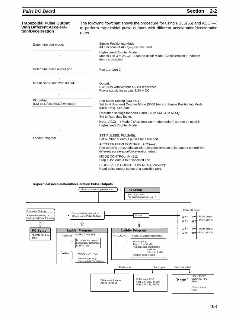
The following flowchart shows the procedure for using PULS(65) and ACC(––)to perform trapezoidal pulse outputs with different acceleration/decelerationrates.
Determine port mode.
Determine pulse output port.
Mount Board and wire output.
PC Setup(DM 6611/DM 6643/DM 6644)
Ladder Program
Simple Positioning Mode:All functions of ACC(––) can be used.
High-speed Counter Mode:Modes 1 to 3 of ACC(––) can be used; Mode 0 (Acceleration + Indepen-dent) is disabled.
Port 1 or port 2.
Output:CW/CCW with/without 1.6 kΩ resistance. Power supply for output: 5/24 V DC
Port Mode Setting (DM 6611):Set to High-speed Counter Mode (0000 Hex) or Simple Positioning Mode(0001 Hex). See note.
Operation settings for ports 1 and 2 (DM 6643/DM 6644):Set to fixed duty factor.
Note: ACC(––) Mode 0 (Acceleration + Independent) cannot be used inHigh-speed Counter Mode.
SET PULSES, PULS(65):Set number of output pulses for each port.
ACCELERATION CONTROL, ACC(––):Port-specific trapezoidal acceleration/deceleration pulse output control withdifferent acceleration/deceleration rates.
MODE CONTROL, INI(61):Stop pulse output to a specified port.
HIGH-SPEED COUNTER PV READ, PRV(62):Read pulse output status of a specified port.
Fixed duty factor pulse output
Trapezoidal Acceleration/Deceleration Pulse Outputs
ACCELERATION CONTROL
No. of pulses output8-digit BCD (00000001to 16777215)
MODE CONTROL
Mode settingTarget: 0 to 50 kHzAcc/dece rate (separate):
4.08 ms 10 Hz to 2 kHz
Starting pulse output
Each cycle Each execution
Pulse output statusAR 05 to AR 06
Pulse output PVPort 1: IR 237, IR 236Port 2: IR 239, IR238
HIGH-SPEEDCOUNTER PVREAD
Output statusread
Pulse I/O Board
– Pulse output
– Port 1 (CN1)
– Pulse output
– Port 2 (CN2)
Port Mode Setting
Simple Positioning orHigh-speed Counter Mode
Pulse output stopPulse output PV change
Output
Each cycle
Trapezoidal Acceleration/Deceleration Pulse Outputs
PC SetupBits 12 to 15 ofDM 6643/DM 6644 set to 0.
Ladder ProgramOUTPUT PULSES
Ladder ProgramPC SetupSet DM 6611 to0001.
Trapezoidal Pulse OutputWith Different Accelera-tion/Deceleration
2-2SectionPulse I/O Board
104
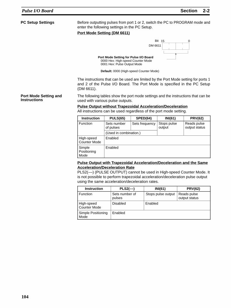
Before outputting pulses from port 1 or 2, switch the PC to PROGRAM mode andenter the following settings in the PC Setup.
Port Mode Setting (DM 6611)
15 0
DM 6611
Bit
Port Mode Setting for Pulse I/O Board0000 Hex: High-speed Counter Mode0001 Hex: Pulse Output Mode
Default: 0000 (High-speed Counter Mode)
The instructions that can be used are limited by the Port Mode setting for ports 1and 2 of the Pulse I/O Board. The Port Mode is specified in the PC Setup(DM 6611).
The following tables show the port mode settings and the instructions that can beused with various pulse outputs.
Pulse Output without Trapezoidal Acceleration/DecelerationAll instructions can be used regardless of the port mode setting.
Instruction PULS(65) SPED(64) INI(61) PRV(62)Function Sets number
of pulsesSets frequency Stops pulse
outputReads pulseoutput status
(Used in combination.)
High-speedCounter Mode
Enabled
SimplePositioningMode
Enabled
Pulse Output with Trapezoidal Acceleration/Deceleration and the SameAcceleration/Deceleration RatePLS2(––) (PULSE OUTPUT) cannot be used in High-speed Counter Mode. Itis not possible to perform trapezoidal acceleration/deceleration pulse outputusing the same acceleration/deceleration rates.
Instruction PLS2(––) INI(61) PRV(62)
Function Sets number ofpulses
Stops pulse output Reads pulseoutput status
High-speedCounter Mode
Disabled Enabled
Simple PositioningMode
Enabled
PC Setup Settings
Port Mode Setting andInstructions

2-2SectionPulse I/O Board
105
Pulse Output with Trapezoidal Acceleration/Deceleration and SeparateAcceleration/Deceleration RatesThe only limitation that exists is that ACC(––) (ACCELERATION CONTROL) inMode 0 (Acceleration + Independent) cannot be used in High-speed CounterMode.
Instruction PULS(65) ACC(––) INI(61) PRV(62)
Function Sets numberof pulses
Acceleration/Decelerationrates(separatesettings)
Sets frequency
Starts pulseoutput
Stops pulseoutput
Reads pulseoutput status
(Used in combination.)
High-speedCounter Mode
Enabled Mode 0 (Acc.+Independent):Disabled
Mode 3:Enabled
Enabled
SimplePositioningMode
Enabled
The setting in DM 6611 is read only when the CQM1H is started. If this setting ischanged, the PC must be turned OFF and ON again to enable the new value.
Operation Settings for Ports 1 and 2 (DM 6643 and DM 6644)
The diagram below shows how port 1 (DM 6643) and port 2 (DM 6644) are set toperform fixed duty factor pulse output, which is the default pulse output format.The settings for ports 1 and 2 can differ.
15 0
DM 6643 0Bit
Port 1 Pulse Type0: Fixed duty factor pulse outputSet to fixed duty factor when per-forming standard pulse output.1: Variable duty factor pulse output
Default: 0 (Fixed duty factor pulse output)
15 0
DM 6644 0Bit
Port 2 Pulse T ype0: Fixed duty factor pulse outputSet to fixed duty factor when per-forming standard pulse output.1: Variable duty factor pulse output
Default: 0 (Fixed duty factor pulse output)
Variable duty factor pulses cannot be output from a port if it has been set to per-form standard pulse output.
The following examples show programs that controls pulse output from ports 1and 2. Before running the programs, check that the settings in the PC Setup areas follows:DM 6611: 0001 (Simple Positioning Mode)DM 6643: 0000 (Fixed duty factor pulse output from port 1)DM 6644: 0000 (Fixed duty factor pulse output from port 2)
Starting Pulse Output at Specified Frequency
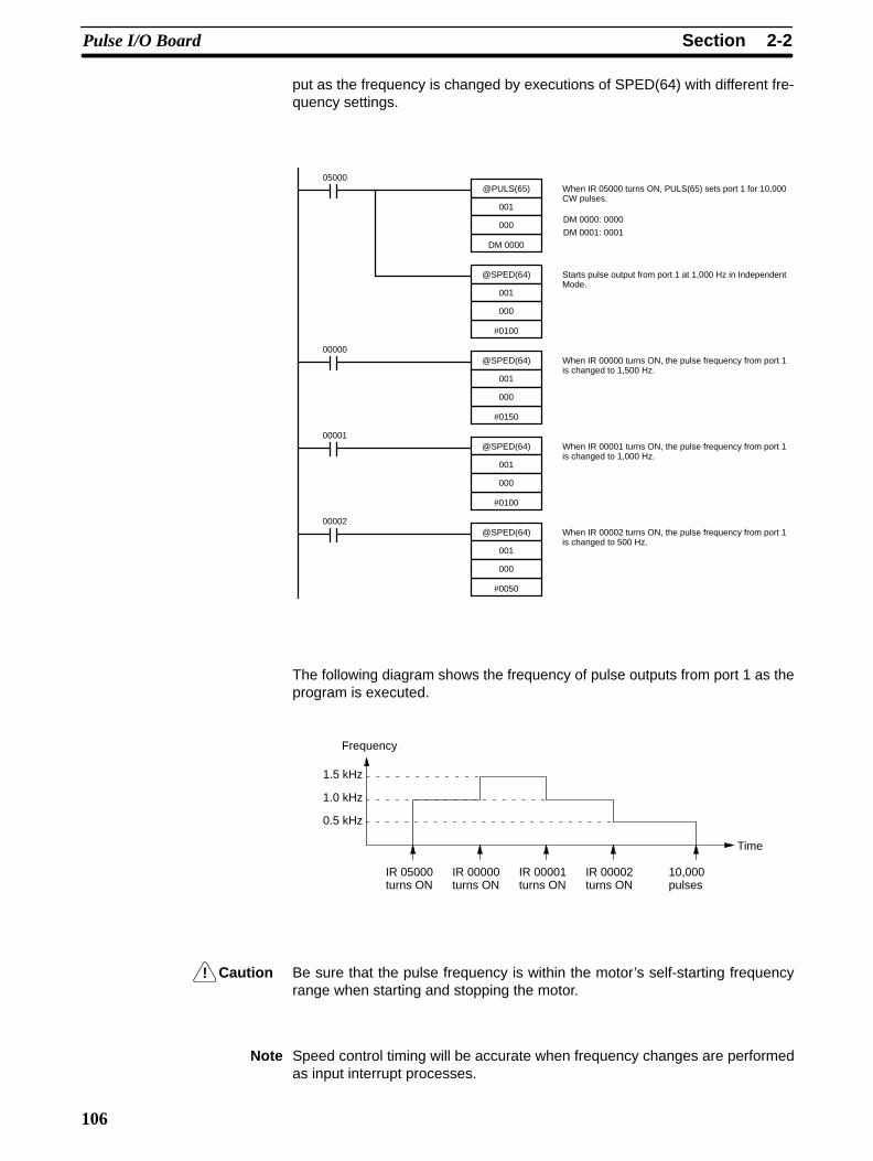
The following example shows PULS(65) and SPED(64) used to control a pulseoutput from port 1. The number of pulses specified in PULS(65) (10,000) are out-
Examples
Example 1: StartingPulse Output withPULS(65) and SPED(64)
!
2-2SectionPulse I/O Board
106
put as the frequency is changed by executions of SPED(64) with different fre-quency settings.
@PULS(65)
000
001
05000
DM 0000
@SPED(64)
000
001
#0100
00000@SPED(64)
000
001
#0150
00001@SPED(64)
000
001
#0100
00002@SPED(64)
000
001
#0050
When IR 05000 turns ON, PULS(65) sets port 1 for 10,000CW pulses.
Starts pulse output from port 1 at 1,000 Hz in IndependentMode.
When IR 00000 turns ON, the pulse frequency from port 1is changed to 1,500 Hz.
When IR 00001 turns ON, the pulse frequency from port 1is changed to 1,000 Hz.
When IR 00002 turns ON, the pulse frequency from port 1is changed to 500 Hz.
DM 0000: 0000
DM 0001: 0001
The following diagram shows the frequency of pulse outputs from port 1 as theprogram is executed.
Frequency
Time
1.5 kHz
1.0 kHz
0.5 kHz
IR 05000turns ON
IR 00000turns ON
IR 00001turns ON
IR 00002turns ON
10,000pulses
Caution Be sure that the pulse frequency is within the motor’s self-starting frequencyrange when starting and stopping the motor.
Note Speed control timing will be accurate when frequency changes are performedas input interrupt processes.
!
2-2SectionPulse I/O Board
107
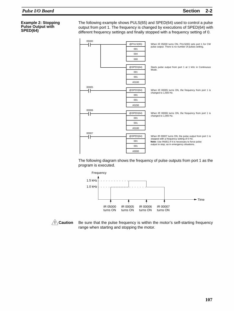
The following example shows PULS(65) and SPED(64) used to control a pulseoutput from port 1. The frequency is changed by executions of SPED(64) withdifferent frequency settings and finally stopped with a frequency setting of 0.
@PULS(65)
004
001
05000
000
@SPED(64)
001
001
#0100
00005@SPED(64)
001
001
#0150
00006@SPED(64)
001
001
#0100
00007@SPED(64)
001
001
#0000
When IR 05000 turns ON, PULS(65) sets port 1 for CWpulse output. There is no number of pulses setting.
Starts pulse output from port 1 at 1 kHz in ContinuousMode.
When IR 00005 turns ON, the frequency from port 1 ischanged to 1,500 Hz.
When IR 00006 turns ON, the frequency from port 1 ischanged to 1,000 Hz.
When IR 00007 turns ON, the pulse output from port 1 isstopped with a frequency setting of 0 Hz.Note: Use INI(61) if it is necessary to force pulseoutput to stop, as in emergency situations.
The following diagram shows the frequency of pulse outputs from port 1 as theprogram is executed.
Frequency
Time
1.5 kHz
1.0 kHz
IR 05000turns ON
IR 00005turns ON
IR 00006turns ON
IR 00007turns ON
Caution Be sure that the pulse frequency is within the motor’s self-starting frequencyrange when starting and stopping the motor.
Example 2: StoppingPulse Output withSPED(64)
2-2SectionPulse I/O Board
108
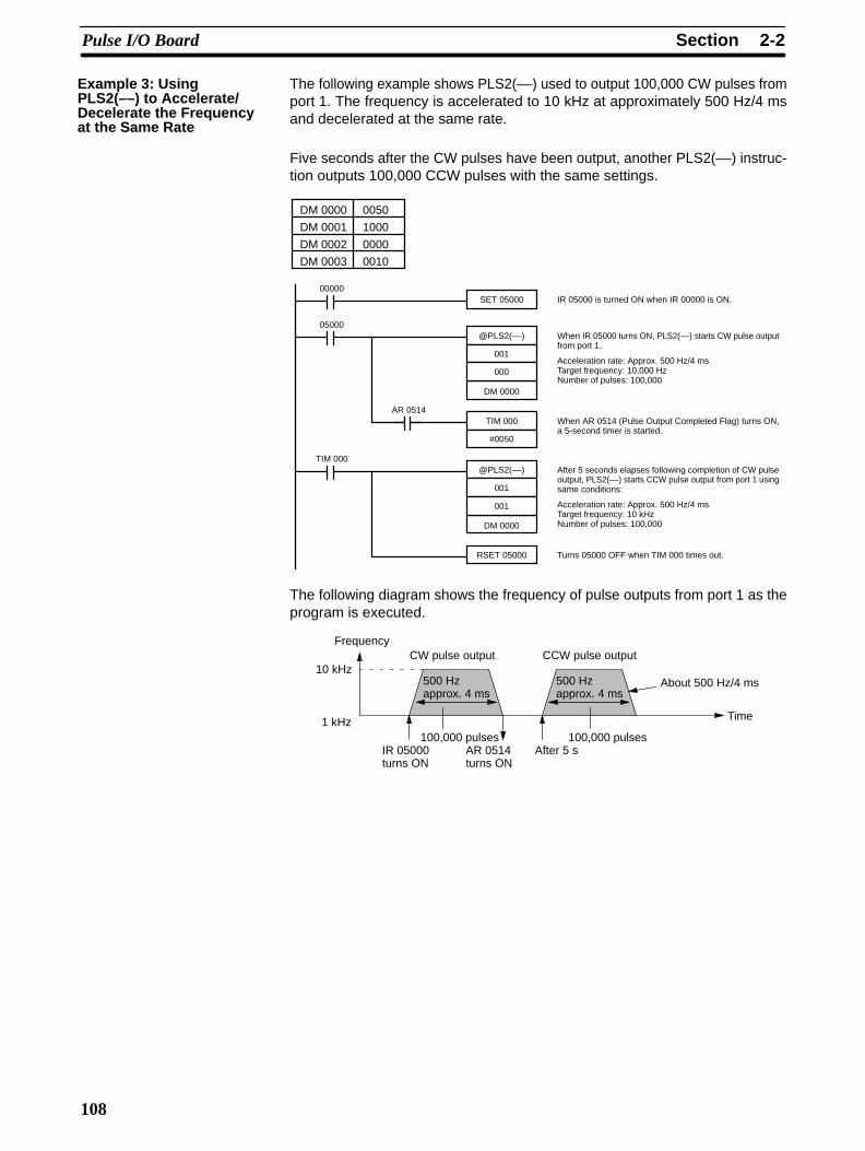
The following example shows PLS2(––) used to output 100,000 CW pulses fromport 1. The frequency is accelerated to 10 kHz at approximately 500 Hz/4 msand decelerated at the same rate.
Five seconds after the CW pulses have been output, another PLS2(––) instruc-tion outputs 100,000 CCW pulses with the same settings.
@PLS2(––)
000
001
05000
DM 0000
TIM 000
#0050
When IR 05000 turns ON, PLS2(––) starts CW pulse outputfrom port 1.
Acceleration rate: Approx. 500 Hz/4 msTarget frequency: 10,000 HzNumber of pulses: 100,000
When AR 0514 (Pulse Output Completed Flag) turns ON,a 5-second timer is started.
SET 0500000000
IR 05000 is turned ON when IR 00000 is ON.
AR 0514
@PLS2(––)
001
001
TIM 000
DM 0000
After 5 seconds elapses following completion of CW pulseoutput, PLS2(––) starts CCW pulse output from port 1 usingsame conditions:
Acceleration rate: Approx. 500 Hz/4 msTarget frequency: 10 kHzNumber of pulses: 100,000
RSET 05000 Turns 05000 OFF when TIM 000 times out.
DM 0000 0050
DM 0001 1000
DM 0002 0000
DM 0003 0010
The following diagram shows the frequency of pulse outputs from port 1 as theprogram is executed.
Frequency
Time
10 kHz
IR 05000turns ON
AR 0514turns ON
CW pulse output CCW pulse output
After 5 s
About 500 Hz/4 ms500 Hzapprox. 4 ms
500 Hzapprox. 4 ms
100,000 pulses 100,000 pulses1 kHz
Example 3: UsingPLS2(––) to Accelerate/Decelerate the Frequencyat the Same Rate

2-2SectionPulse I/O Board
109
The following example shows Mode 0 of ACC(––) used to output 10,000 CWpulses from port 1. The frequency is accelerated to 10 kHz at approximately1 kHz/4 ms and decelerated to 1 kHz at approximately 250 Hz/4 ms. Decelera-tion begins after 9,100 pulses have been output.
@PULS(65)
002
001
00000
DM 0000
@ACC(––)
000
001
DM 0004
When IR 00000 turns ON, PULS(65) sets port 1 for CWpulse output. The total number of pulses is set to 10,000and the deceleration point is set to 9,100 pulses.
Starts CW pulse output from port 1.
Acceleration rate: Approx. 1000 Hz/4 msTarget frequency after acceleration: 10,000 HzDeceleration rate: Approx. 250 Hz/4 msTarget frequency after deceleration: 1 kHzFollowing deceleration, pulse output starts at target fre-quency of approx. 500 Hz/4 ms.
DM 0000 0000
DM 0001 0001
DM 0002 9100
DM 0003 0000
DM 0004 0100
DM 0005 1000
DM 0006 0025
DM 0007 0050
The following diagram shows the frequency of pulse outputs from port 1 as theprogram is executed.
Frequency
Time
10 kHz
IR 00000turns ON
1 kHz
9,100pulses
10,000pulses
About 1 kHz/4 msAbout 250 Hz/4 ms
The following example shows Mode 1 of ACC(––) used to increase the frequen-cy of a pulse output from port 1. The frequency is accelerated from 1 kHz to20 kHz at approximately 500 Hz/4 ms.
@PULS(65)
005
002
00000
000
@SPED(64)
001
002
#0100
When IR 00000 turns ON, PULS(65) sets port 2 for CCWpulse output. The number of pulses is not set.
Starts 1,000 Hz (1 kHz) pulse output from port 2 in Continu-ous Mode.
DM 0000 0050
DM 0001 2000
@ACC(––)
001
002
DM 0000
When IR 00001 turns ON, ACC(––) begins accelerating theport 2 pulse output at about 500 Hz/4 ms until it reaches thetarget frequency of 20,000 Hz.
00001
Example 4: UsingACC(––) to Accelerate/Decelerate the Frequencyat Different Rates
Example 5: UsingACC(––) to Acceleratethe Frequency at aSpecified Rate
2-2SectionPulse I/O Board
110
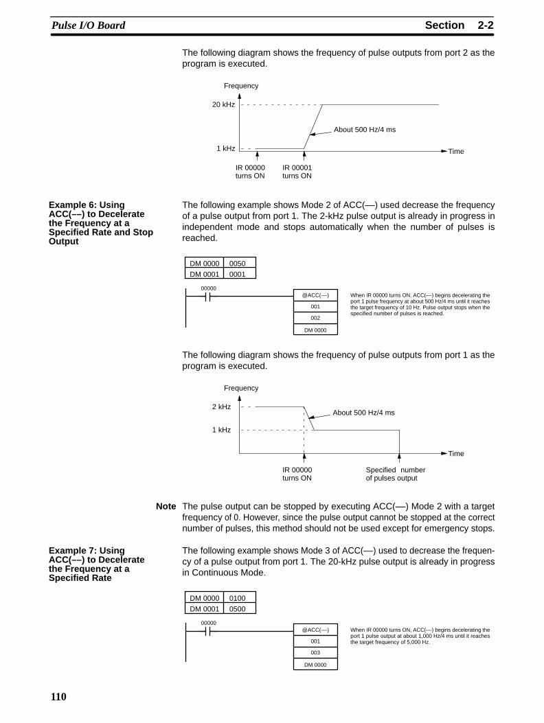
The following diagram shows the frequency of pulse outputs from port 2 as theprogram is executed.
Frequency
Time
20 kHz
IR 00001turns ON
1 kHz
About 500 Hz/4 ms
IR 00000turns ON
The following example shows Mode 2 of ACC(––) used decrease the frequencyof a pulse output from port 1. The 2-kHz pulse output is already in progress inindependent mode and stops automatically when the number of pulses isreached.
DM 0000 0050
DM 0001 0001
@ACC(––)
002
001
DM 0000
When IR 00000 turns ON, ACC(––) begins decelerating theport 1 pulse frequency at about 500 Hz/4 ms until it reachesthe target frequency of 10 Hz. Pulse output stops when thespecified number of pulses is reached.
00000
The following diagram shows the frequency of pulse outputs from port 1 as theprogram is executed.
Frequency
Time
2 kHz
Specified numberof pulses output
1 kHz
About 500 Hz/4 ms
IR 00000turns ON
Note The pulse output can be stopped by executing ACC(––) Mode 2 with a targetfrequency of 0. However, since the pulse output cannot be stopped at the correctnumber of pulses, this method should not be used except for emergency stops.
The following example shows Mode 3 of ACC(––) used to decrease the frequen-cy of a pulse output from port 1. The 20-kHz pulse output is already in progressin Continuous Mode.
DM 0000 0100
DM 0001 0500
@ACC(––)
003
001
DM 0000
When IR 00000 turns ON, ACC(––) begins decelerating theport 1 pulse output at about 1,000 Hz/4 ms until it reachesthe target frequency of 5,000 Hz.
00000
Example 6: UsingACC(––) to Deceleratethe Frequency at aSpecified Rate and StopOutput
Example 7: UsingACC(––) to Deceleratethe Frequency at aSpecified Rate
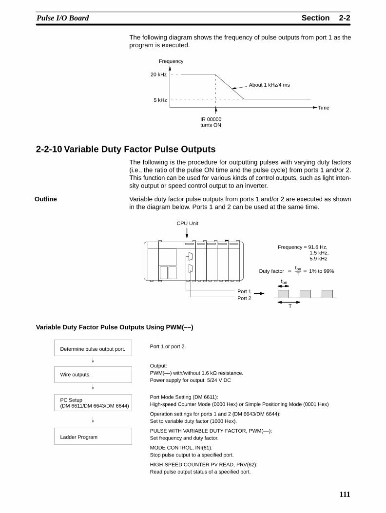
2-2SectionPulse I/O Board
111
The following diagram shows the frequency of pulse outputs from port 1 as theprogram is executed.
Frequency
Time
20 kHz
5 kHz
About 1 kHz/4 ms
IR 00000turns ON
2-2-10 Variable Duty Factor Pulse OutputsThe following is the procedure for outputting pulses with varying duty factors(i.e., the ratio of the pulse ON time and the pulse cycle) from ports 1 and/or 2.This function can be used for various kinds of control outputs, such as light inten-sity output or speed control output to an inverter.
Variable duty factor pulse outputs from ports 1 and/or 2 are executed as shownin the diagram below. Ports 1 and 2 can be used at the same time.
T
ton
Duty factor
ton
T 1% to 99%
CPU Unit
Port 1Port 2
Frequency = 91.6 Hz,1.5 kHz,5.9 kHz
Variable Duty Factor Pulse Outputs Using PWM(––)
Determine pulse output port.
Wire outputs.
PC Setup(DM 6611/DM 6643/DM 6644)
Ladder Program
Port 1 or port 2.
Output:PWM(––) with/without 1.6 kΩ resistance.Power supply for output: 5/24 V DC
Port Mode Setting (DM 6611):High-speed Counter Mode (0000 Hex) or Simple Positioning Mode (0001 Hex)
Operation settings for ports 1 and 2 (DM 6643/DM 6644):Set to variable duty factor (1000 Hex).
PULSE WITH VARIABLE DUTY FACTOR, PWM(––):Set frequency and duty factor.
MODE CONTROL, INI(61):Stop pulse output to a specified port.
HIGH-SPEED COUNTER PV READ, PRV(62):Read pulse output status of a specified port.
Outline
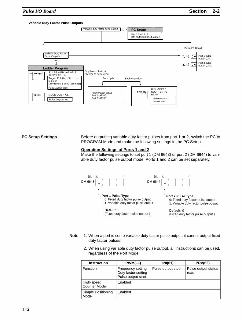
2-2SectionPulse I/O Board
112
Variable duty factor pulse output
Variable Duty FactorPulse Outputs
Duty factor: Ratio ofON time to pulse cycle.
MODE CONTROL
Each cycle Each execution
Pulse output statusPort 1: AR 05Port 2: AR 06
HIGH-SPEEDCOUNTER PVREAD
Pulse I/O Board
Port 1 pulseoutput (CN1)
Port 2 pulseoutput (CN2)
PULSE WITH VARIABLEDUTY FACTORTarget: 91.6 Hz, 1.5 kHz, or5.9 kHzDuty factor: 1 to 99 (see note)
Pulse output start
Pulse output stop Pulse outputstatus read
Variable Duty Factor Pulse Outputs
PC SetupBits 12 to 15 ofDM 6643/DM 6644 set to 1.
Ladder Program
Before outputting variable duty factor pulses from port 1 or 2, switch the PC toPROGRAM Mode and make the following settings in the PC Setup.
Operation Settings of Ports 1 and 2Make the following settings to set port 1 (DM 6643) or port 2 (DM 6644) to vari-able duty factor pulse output mode. Ports 1 and 2 can be set separately.
15 0
DM 6643 1Bit 15 0
DM 6644 1Bit
Port 1 Pulse Type0: Fixed duty factor pulse output1: Variable duty factor pulse output
Default: 0 (Fixed duty factor pulse output )
Port 2 Pulse T ype0: Fixed duty factor pulse output1: Variable duty factor pulse output
Default: 0 (Fixed duty factor pulse output )
Note 1. When a port is set to variable duty factor pulse output, it cannot output fixedduty factor pulses.
2. When using variable duty factor pulse output, all instructions can be used,regardless of the Port Mode.
Instruction PWM(––) INI(61) PRV(62)
Function Frequency settingDuty factor settingPulse output start
Pulse output stop Pulse output statusread
High-speedCounter Mode
Enabled
Simple PositioningMode
Enabled
PC Setup Settings
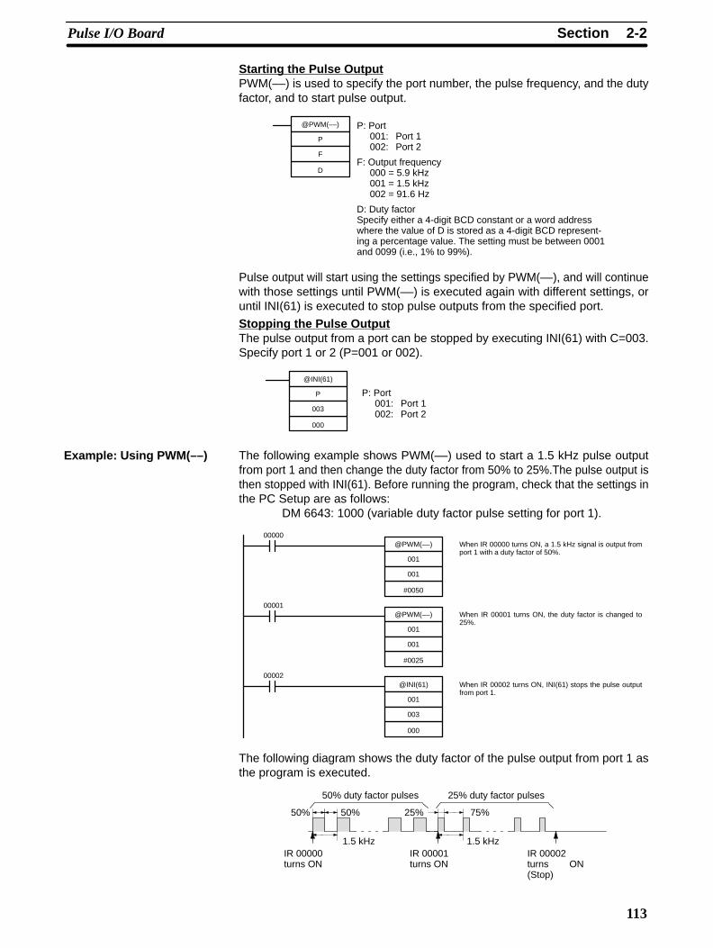
2-2SectionPulse I/O Board
113
Starting the Pulse OutputPWM(––) is used to specify the port number, the pulse frequency, and the dutyfactor, and to start pulse output.
@PWM(––)
F
P
D
P: Port001: Port 1002: Port 2
F: Output frequency000 = 5.9 kHz001 = 1.5 kHz002 = 91.6 Hz
D: Duty factorSpecify either a 4-digit BCD constant or a word addresswhere the value of D is stored as a 4-digit BCD represent-ing a percentage value. The setting must be between 0001and 0099 (i.e., 1% to 99%).
Pulse output will start using the settings specified by PWM(––), and will continuewith those settings until PWM(––) is executed again with different settings, oruntil INI(61) is executed to stop pulse outputs from the specified port.
Stopping the Pulse OutputThe pulse output from a port can be stopped by executing INI(61) with C=003.Specify port 1 or 2 (P=001 or 002).
@INI(61)
003
P
000
P: Port001: Port 1002: Port 2
The following example shows PWM(––) used to start a 1.5 kHz pulse outputfrom port 1 and then change the duty factor from 50% to 25%.The pulse output isthen stopped with INI(61). Before running the program, check that the settings inthe PC Setup are as follows:
DM 6643: 1000 (variable duty factor pulse setting for port 1).
00000@PWM(––)
001
001
#0050
00001@PWM(––)
001
001
#0025
00002@INI(61)
003
001
000
When IR 00000 turns ON, a 1.5 kHz signal is output fromport 1 with a duty factor of 50%.
When IR 00001 turns ON, the duty factor is changed to25%.
When IR 00002 turns ON, INI(61) stops the pulse outputfrom port 1.
The following diagram shows the duty factor of the pulse output from port 1 asthe program is executed.
50% duty factor pulses 25% duty factor pulses
IR 00001turns ON
IR 00000turns ON
IR 00002turns ON(Stop)
50% 50% 25% 75%
1.5 kHz 1.5 kHz
Example: Using PWM(––)
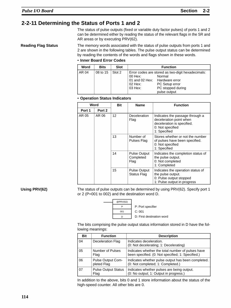
2-2SectionPulse I/O Board
114
2-2-11 Determining the Status of Ports 1 and 2The status of pulse outputs (fixed or variable duty factor pulses) of ports 1 and 2can be determined either by reading the status of the relevant flags in the SR andAR areas or by executing PRV(62).
The memory words associated with the status of pulse outputs from ports 1 and2 are shown in the following tables. The pulse output status can be determinedby reading the contents of the words and flags shown in these words.• Inner Board Error Codes
Word Bits Slot Function
AR 04 08 to 15 Slot 2 Error codes are stored as two-digit hexadecimals:00 Hex: Normal01 and 02 Hex: Hardware error02 Hex: PC Setup error03 Hex: PC stopped during
pulse output
• Operation Status Indicators
Word Bit Name Function
Port 1 Port 2AR 05 AR 06 12 Deceleration
FlagIndicates the passage through adeceleration point whendeceleration is specified.0: Not specified1: Specified
13 Number ofPulses Flag
Stores whether or not the numberof pulses have been specified.0: Not specified1: Specified
14 Pulse OutputCompletedFlag
Indicates the completion status ofthe pulse output.0: Not completed1: Completed
15 Pulse OutputStatus Flag
Indicates the operation status ofthe pulse output.0: Pulse output stopped1: Pulse output in progress
The status of pulse outputs can be determined by using PRV(62). Specify port 1or 2 (P=001 to 002) and the destination word D.
@PRV(62)
001
P
D
P: Port specifier
C: 001
D: First destination word
The bits comprising the pulse output status information stored in D have the fol-lowing meanings:
Bit Function Description
04 Deceleration Flag Indicates deceleration.(0: Not decelerating; 1: Decelerating)
05 Number of PulsesFlag
Indicates whether the total number of pulses havebeen specified. (0: Not specified; 1: Specified.)
06 Pulse Output Com-pleted Flag
Indicates whether pulse output has been completed.(0: Not completed; 1: Completed.)
07 Pulse Output StatusFlag
Indicates whether pulses are being output.(0: No output; 1: Output in progress.)
In addition to the above, bits 0 and 1 store information about the status of thehigh-speed counter. All other bits are 0.
Reading Flag Status
Using PRV(62)
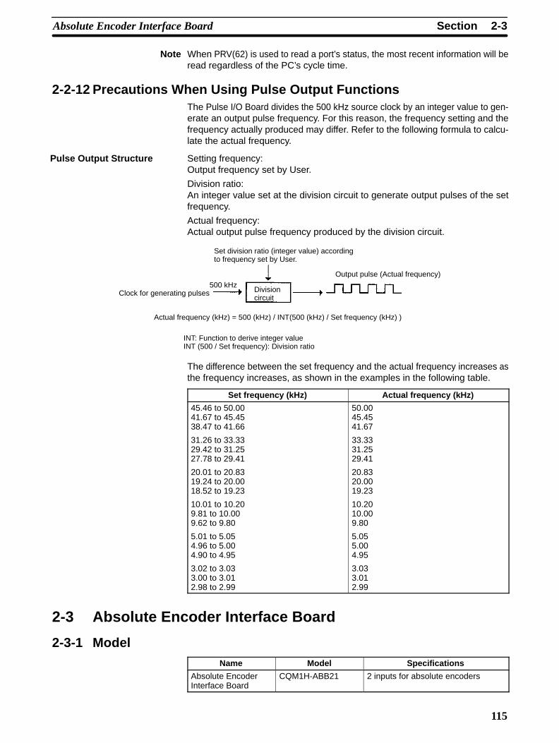
2-3SectionAbsolute Encoder Interface Board
115
Note When PRV(62) is used to read a port’s status, the most recent information will beread regardless of the PC’s cycle time.
2-2-12 Precautions When Using Pulse Output FunctionsThe Pulse I/O Board divides the 500 kHz source clock by an integer value to gen-erate an output pulse frequency. For this reason, the frequency setting and thefrequency actually produced may differ. Refer to the following formula to calcu-late the actual frequency.
Setting frequency:Output frequency set by User.
Division ratio:An integer value set at the division circuit to generate output pulses of the setfrequency.
Actual frequency:Actual output pulse frequency produced by the division circuit.
Set division ratio (integer value) accordingto frequency set by User.
Clock for generating pulses500 kHz
Divisioncircuit
Output pulse (Actual frequency)
Actual frequency (kHz) = 500 (kHz) / INT(500 (kHz) / Set frequency (kHz) )
INT: Function to derive integer valueINT (500 / Set frequency): Division ratio
The difference between the set frequency and the actual frequency increases asthe frequency increases, as shown in the examples in the following table.
Set frequency (kHz) Actual frequency (kHz)
45.46 to 50.0041.67 to 45.4538.47 to 41.66
31.26 to 33.3329.42 to 31.2527.78 to 29.41
20.01 to 20.8319.24 to 20.0018.52 to 19.23
10.01 to 10.209.81 to 10.009.62 to 9.80
5.01 to 5.054.96 to 5.004.90 to 4.95
3.02 to 3.033.00 to 3.012.98 to 2.99
50.0045.4541.67
33.3331.2529.41
20.8320.0019.23
10.2010.009.80
5.055.004.95
3.033.012.99
2-3 Absolute Encoder Interface Board
2-3-1 ModelName Model Specifications
Absolute EncoderInterface Board
CQM1H-ABB21 2 inputs for absolute encoders
Pulse Output Structure