Embed Size (px)
Citation preview
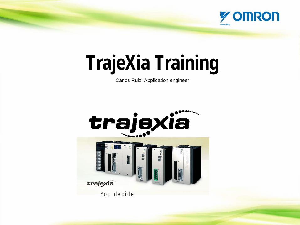
TrajeXia TrainingCarlos Ruiz, Application engineer
CONTENTS
TrajeXia OverviewHardware and general specification TrajeXia ToolsTrajexia ArchitectureProgramming TrajeXiaHow I do… with TrajeXia?CommunicationTrajeXia success histories
CONTENTS: TrajeXia Overview
-What is Trajexia?-Key concept. Freedom-TrajeXia system Architecture-Some typical application.-Available documentation-TrajeXia Minisite
TrajeXia Overview: What is TrajeXia
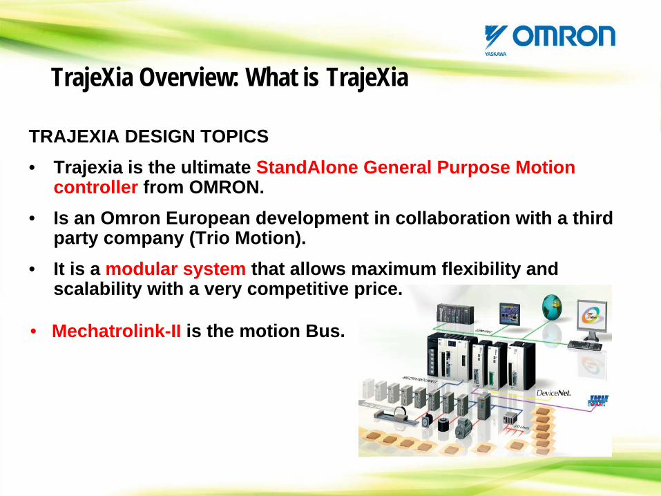
TRAJEXIA DESIGN TOPICS• Trajexia is the ultimate StandAlone General Purpose Motion
controller from OMRON.• Is an Omron European development in collaboration with a third
party company (Trio Motion).• It is a modular system that allows maximum flexibility and
scalability with a very competitive price.
• Mechatrolink-II is the motion Bus.
TrajeXia Overview: What is TrajeXia
TRAJEXIA DESIGN TOPICS
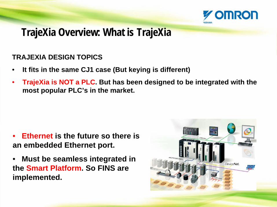
• It fits in the same CJ1 case (But keying is different)
• TrajeXia is NOT a PLC. But has been designed to be integrated with the most popular PLC’s in the market.
• Ethernet is the future so there is an embedded Ethernet port.
• Must be seamless integrated in the Smart Platform. So FINS are implemented.
TrajeXia Overview: What is TrajeXia
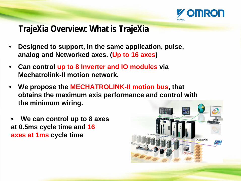
• Designed to support, in the same application, pulse, analog and Networked axes. (Up to 16 axes)
• Can control up to 8 Inverter and IO modules via Mechatrolink-II motion network.
• We propose the MECHATROLINK-II motion bus, that obtains the maximum axis performance and control with the minimum wiring.
• We can control up to 8 axes at 0.5ms cycle time and 16 axes at 1ms cycle time
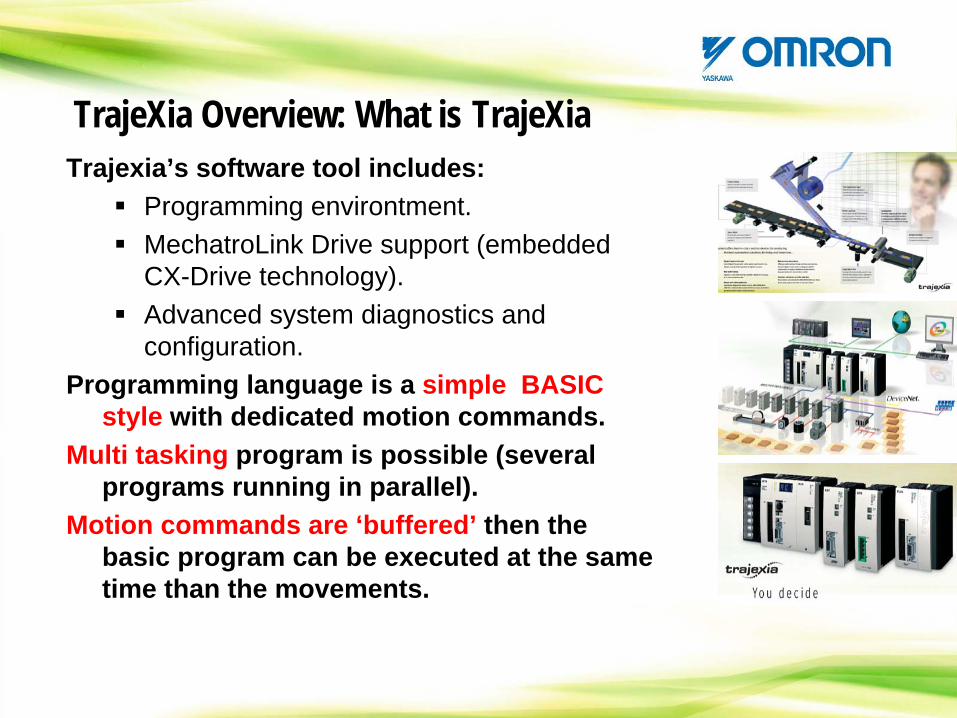
Trajexia’s software tool includes:Programming environtment.MechatroLink Drive support (embedded CX-Drive technology).Advanced system diagnostics and configuration.
Programming language is a simple BASIC style with dedicated motion commands.
Multi tasking program is possible (several programs running in parallel).
Motion commands are ‘buffered’ then the basic program can be executed at the same time than the movements.
TrajeXia Overview: What is TrajeXia
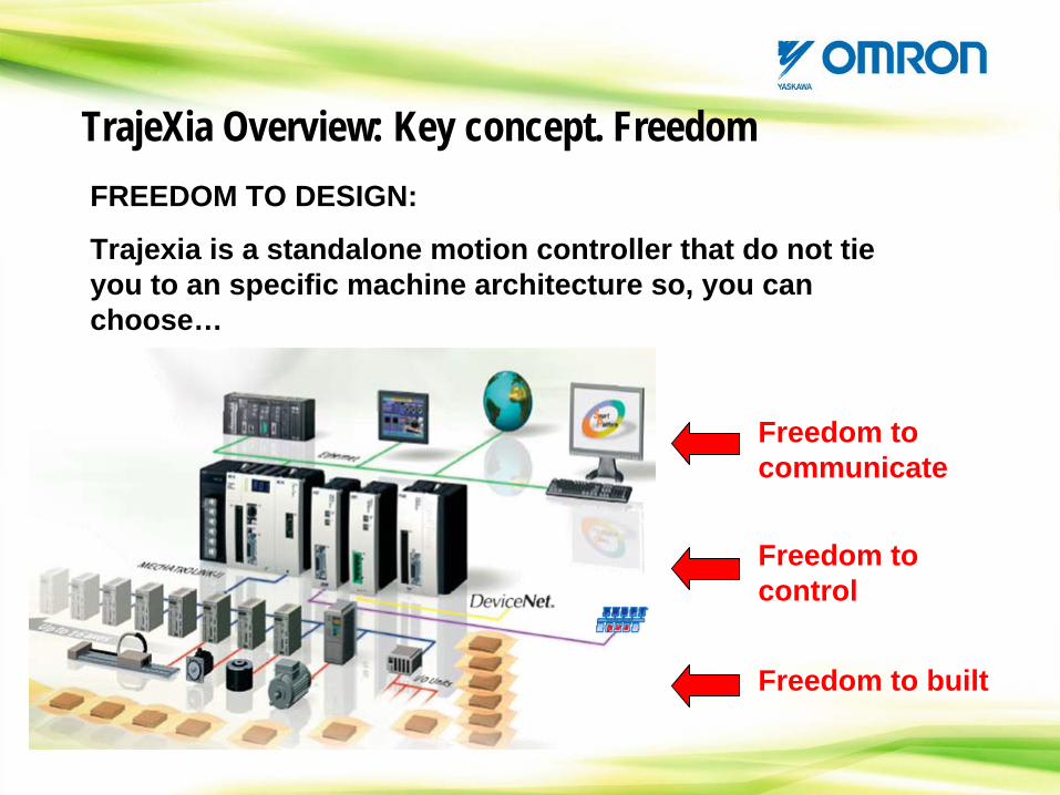
TrajeXia Overview: Key concept. FreedomFREEDOM TO DESIGN:
Trajexia is a standalone motion controller that do not tie you to an specific machine architecture so, you can choose…
Freedom to communicate
Freedom to control
Freedom to built
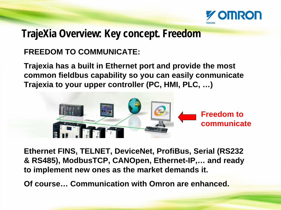
TrajeXia Overview: Key concept. FreedomFREEDOM TO COMMUNICATE:
Trajexia has a built in Ethernet port and provide the most common fieldbus capability so you can easily conmunicate Trajexia to your upper controller (PC, HMI, PLC, …)
Freedom to communicate
Ethernet FINS, TELNET, DeviceNet, ProfiBus, Serial (RS232 & RS485), ModbusTCP, CANOpen, Ethernet-IP,… and ready to implement new ones as the market demands it.
Of course… Communication with Omron are enhanced.
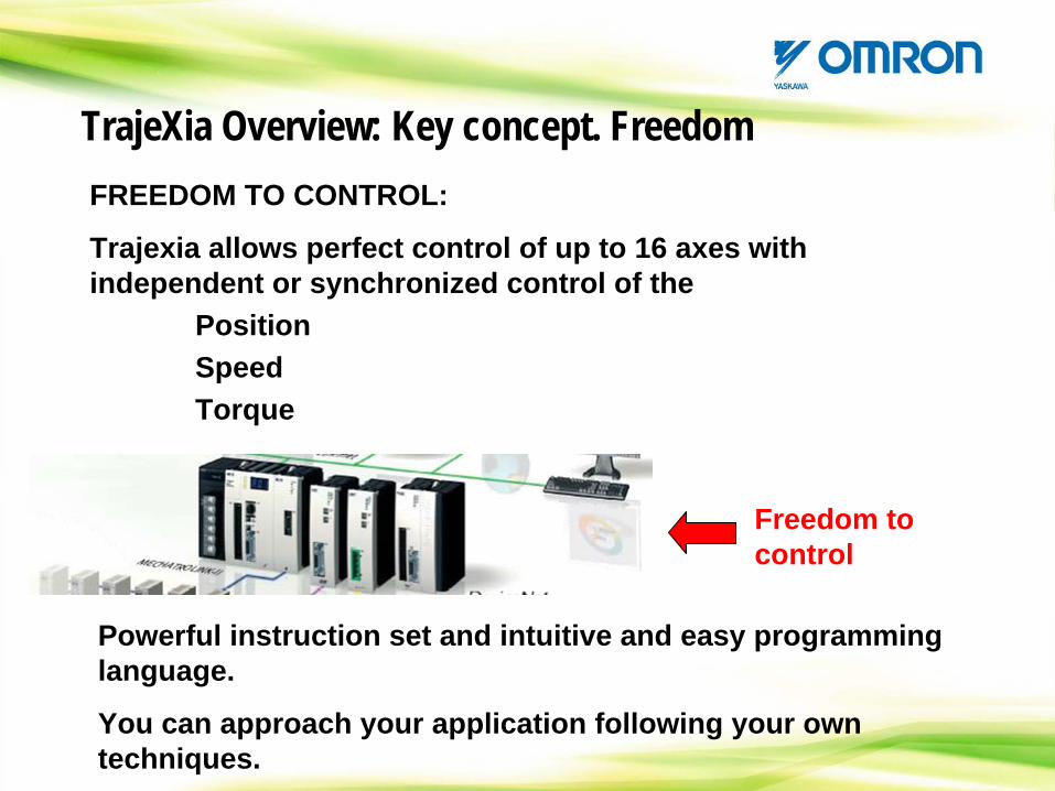
TrajeXia Overview: Key concept. FreedomFREEDOM TO CONTROL:
Trajexia allows perfect control of up to 16 axes with independent or synchronized control of the
PositionSpeedTorque
Freedom to control
Powerful instruction set and intuitive and easy programming language.
You can approach your application following your own techniques.
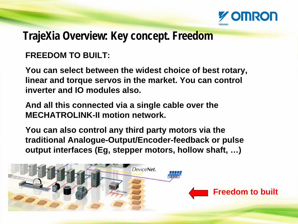
TrajeXia Overview: Key concept. FreedomFREEDOM TO BUILT:
You can select between the widest choice of best rotary, linear and torque servos in the market. You can control inverter and IO modules also.
And all this connected via a single cable over the MECHATROLINK-II motion network.
You can also control any third party motors via the traditional Analogue-Output/Encoder-feedback or pulse output interfaces (Eg, stepper motors, hollow shaft, …)
Freedom to built
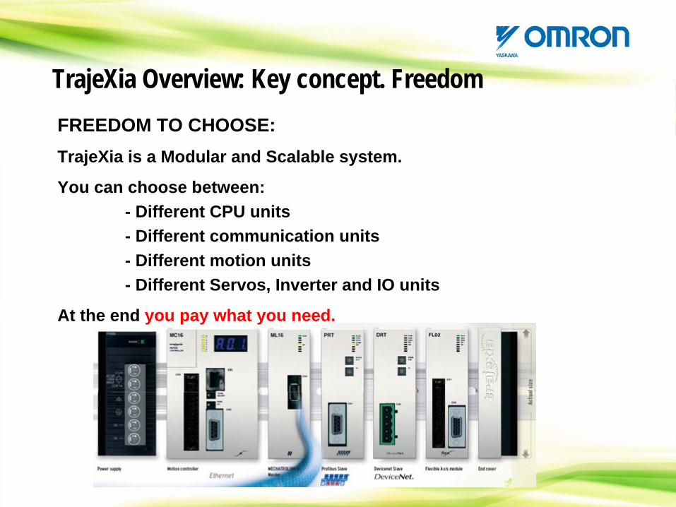
TrajeXia Overview: Key concept. FreedomFREEDOM TO CHOOSE:TrajeXia is a Modular and Scalable system.
You can choose between:- Different CPU units- Different communication units- Different motion units- Different Servos, Inverter and IO units
At the end you pay what you need.
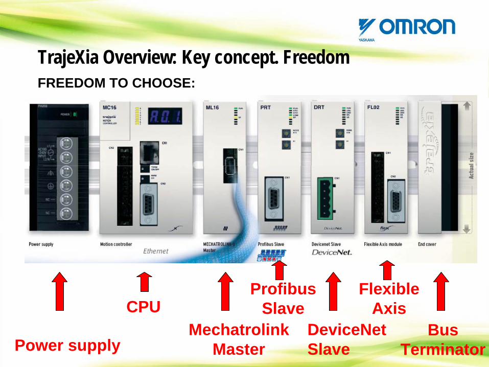
TrajeXia Overview: Key concept. FreedomFREEDOM TO CHOOSE:
Power supply
CPUMechatrolink
Master
Flexible Axis
DeviceNet Slave
Profibus Slave
Bus Terminator

TrajeXia Overview: Key concept. FreedomFREEDOM TO PERFORM:
The most complex Motion application can be solved with TrajeXia. At the moment we have not faced one application that could not be solved…
But we keep the simplicity. The learning curve is extremelly fast. You can become expert in a few days.
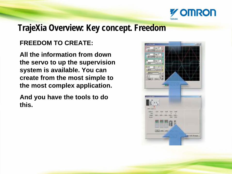
TrajeXia Overview: Key concept. FreedomFREEDOM TO CREATE:
All the information from down the servo to up the supervision system is available. You can create from the most simple to the most complex application.
And you have the tools to do this.
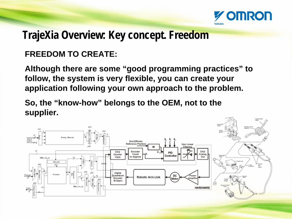
TrajeXia Overview: Key concept. FreedomFREEDOM TO CREATE:
Although there are some “good programming practices” to follow, the system is very flexible, you can create your application following your own approach to the problem.
So, the “know-how” belongs to the OEM, not to the supplier.
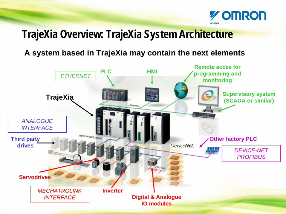
TrajeXia Overview: TrajeXia System ArchitectureA system based in TrajeXia may contain the next elements
Supervisory system (SCADA or similar)
Remote acces for programming and
monitoringHMIPLC
TrajeXia
Servodrives
InverterDigital & Analogue
IO modules
Other factory PLC
MECHATROLINK INTERFACE
Third party drives
ANALOGUE INTERFACE
ETHERNET
DEVICE-NET PROFIBUS
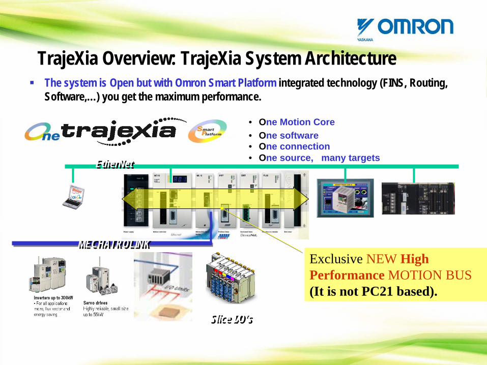
The system is Open but with Omron Smart Platform integrated technology (FINS, Routing, Software,…) you get the maximum performance.
MECHATROLINKMECHATROLINK
• One Motion Core
• One connection• One software
• One source, many targets EtherNetEtherNet
Slice I/O’sSlice I/O’s
Exclusive NEW High Performance MOTION BUS (It is not PC21 based).
TrajeXia Overview: TrajeXia System Architecture
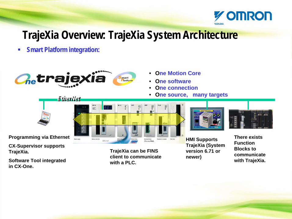
Smart Platform integration:
• One Motion Core
• One connection• One software
• One source, many targets EtherNetEtherNet
TrajeXia Overview: TrajeXia System Architecture
Programming via Ethernet
CX-Supervisor supports TrajeXia.
Software Tool integrated in CX-One.
HMI Supports TrajeXia (System version 6.71 or newer)
There exists Function Blocks to communicate with TrajeXia.
TrajeXia can be FINS client to communicate with a PLC.
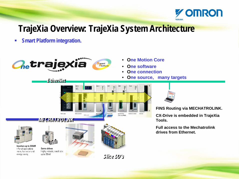
Smart Platform integration.
MECHATROLINKMECHATROLINK
• One Motion Core
• One connection• One software
• One source, many targets EtherNetEtherNet
Slice I/O’sSlice I/O’s
TrajeXia Overview: TrajeXia System Architecture
FINS Routing via MECHATROLINK.
CX-Drive is embedded in TrajeXia Tools.
Full access to the Mechatrolink drives from Ethernet.
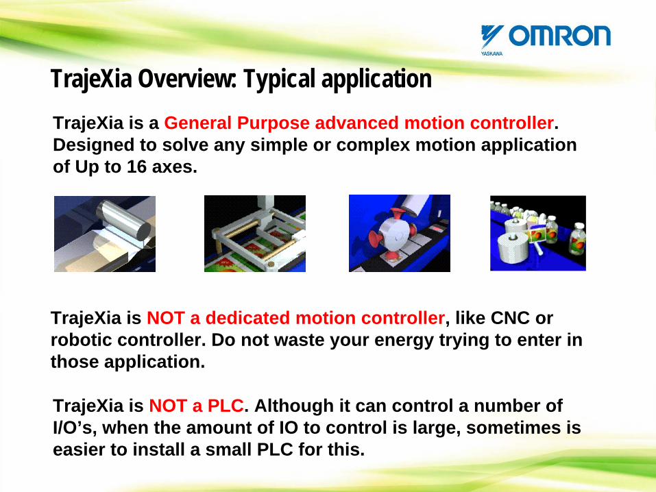
TrajeXia Overview: Typical applicationTrajeXia is a General Purpose advanced motion controller. Designed to solve any simple or complex motion application of Up to 16 axes.
TrajeXia is NOT a dedicated motion controller, like CNC or robotic controller. Do not waste your energy trying to enter in those application.
TrajeXia is NOT a PLC. Although it can control a number of I/O’s, when the amount of IO to control is large, sometimes is easier to install a small PLC for this.

TrajeXia Overview: Typical applicationThe natural Omron market in Europe, for historical reasons, has been packaging.
HORIZONTAL FLOW WRAPPER:

TrajeXia Overview: Typical application
HORIZONTAL FF&S SACHET MACHINE:
TrajeXia Overview: Typical application
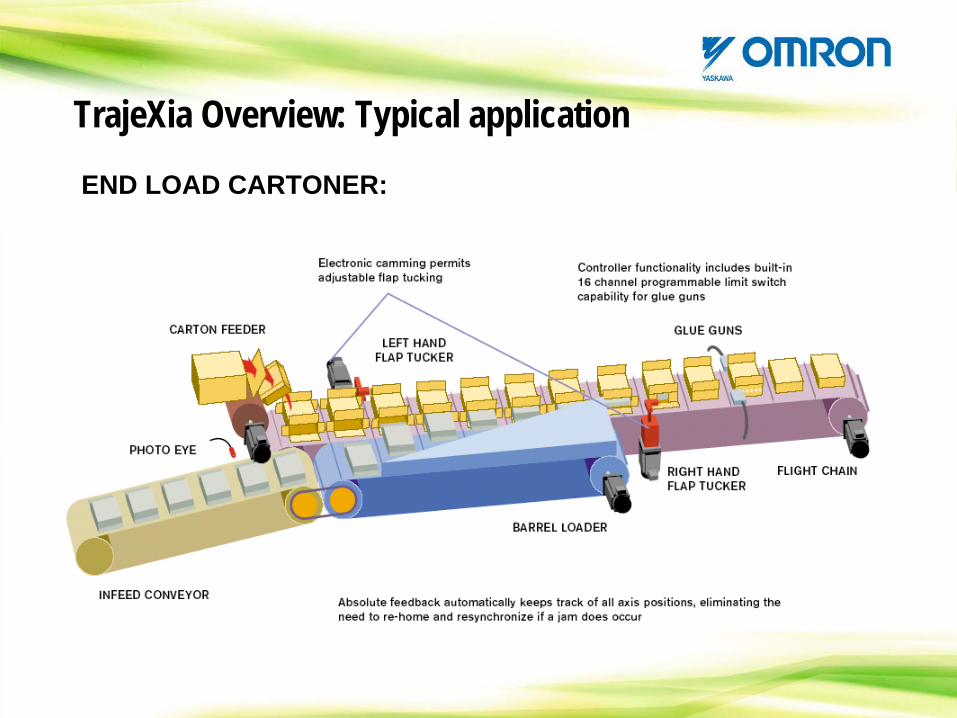
END LOAD CARTONER:
TrajeXia Overview: Available documentation
To support you in the sales and commisioning of the product we have next documentation available:
TrajeXia Combi: Commercial information based in ‘TrajeXia you decide’.
Contains the Datasheet also
TrajeXia Datasheet: Product specification and ordering information
in a quick and easy way.
TrajeXia Overview: Available documentation
Manuals are splitted in 3. Landscape format to fit in a PC screen.
Quick reference guide: Just the information to connect and move a Trajexia system in 10 minutes
Hardware reference: All the necessary hardware information plus
the Trajexia internal architecture.
Programming reference: All what you need to program an application: Command and program reference. Communication protocols. Examples …

TrajeXia Overview: TrajeXia Minisite
www.trajexia.com
It is the second Omron Minisite, after the one from the NS’s
CONTENTS
TrajeXia OverviewHardware and general specificationTrajeXia ToolsTrajexia ArchitectureProgramming TrajeXiaHow I do… with TrajeXia?CommunicationTrajeXia success histories
CONTENTS: Hardware and general specification
-Power supply-CPU Modules-Axes Modules-Communication modules-Mechatrolink bus overview-Mechatrolink nodes-Unit connection rules-System Autoconfiguration
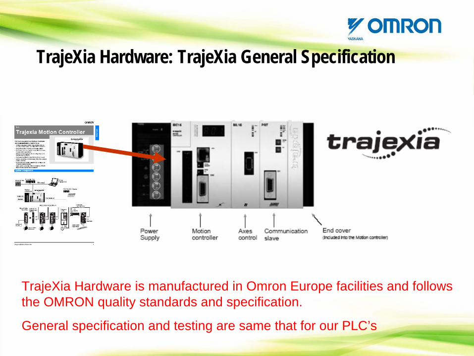
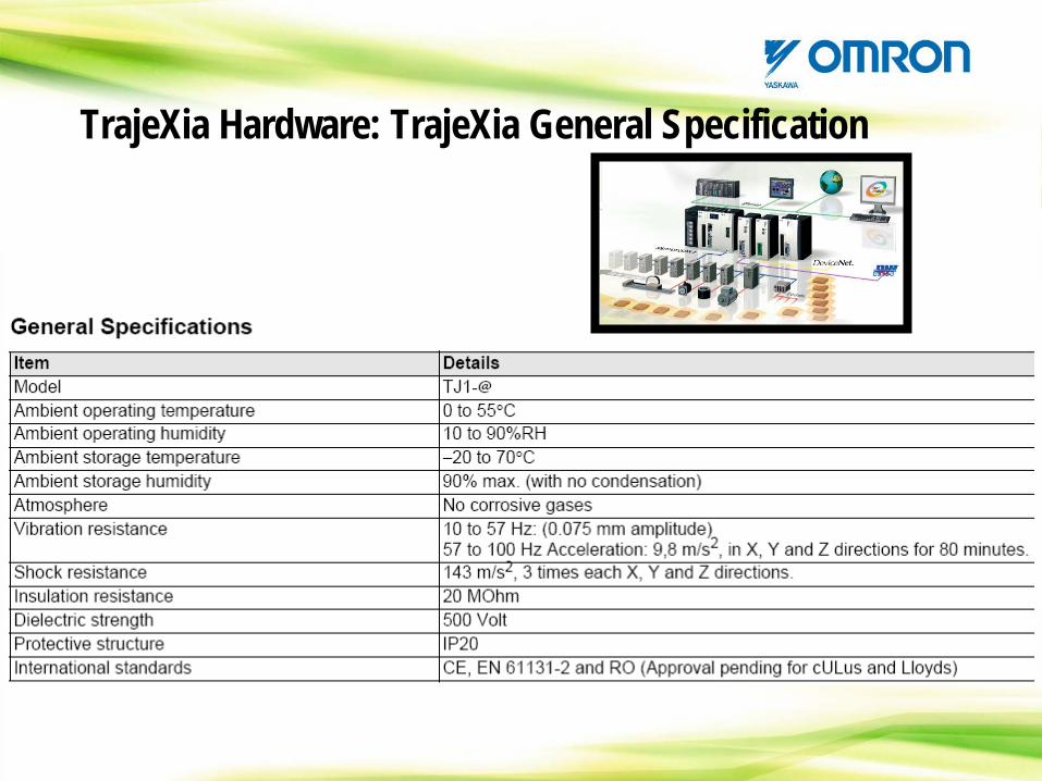
TrajeXia Hardware: TrajeXia General Specification
TrajeXia Hardware is manufactured in Omron Europe facilities and follows the OMRON quality standards and specification.
General specification and testing are same that for our PLC’s
TrajeXia Hardware: TrajeXia General Specification
TrajeXia Hardware: Power supply
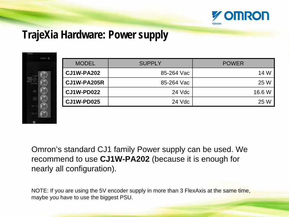
Omron’s standard CJ1 family Power supply can be used. We recommend to use CJ1W-PA202 (because it is enough for nearly all configuration).
MODEL SUPPLY POWER
CJ1W-PA202 85-264 Vac 14 W
CJ1W-PA205R 85-264 Vac 25 W
CJ1W-PD022 24 Vdc 16.6 W
CJ1W-PD025 24 Vdc 25 W
NOTE: If you are using the 5V encoder supply in more than 3 FlexAxis at the same time, maybe you have to use the biggest PSU.
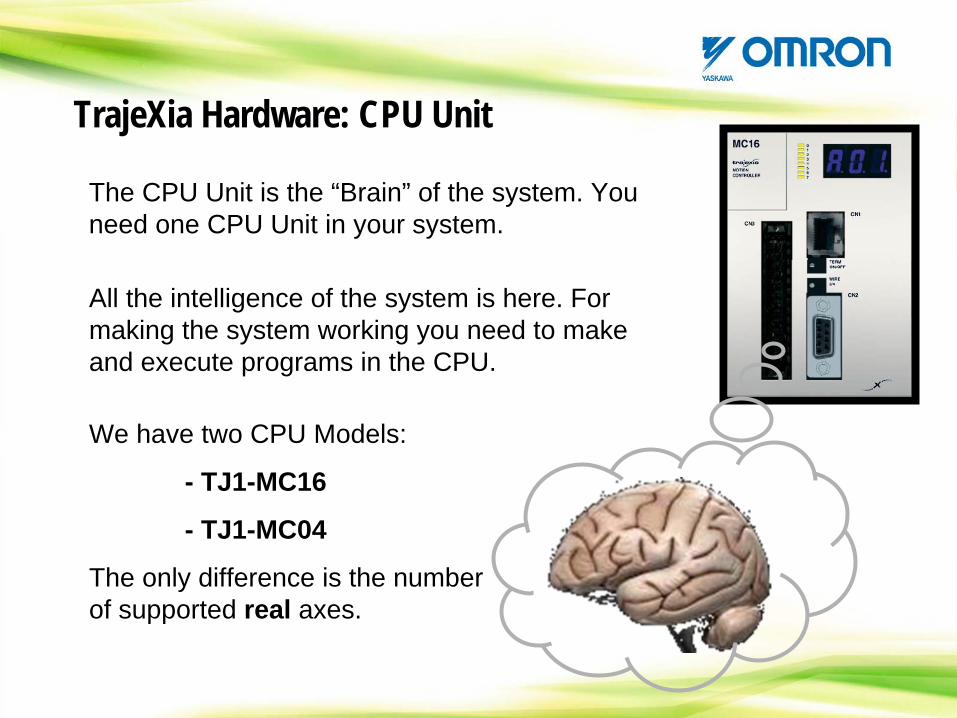
TrajeXia Hardware: CPU Unit
The CPU Unit is the “Brain” of the system. You need one CPU Unit in your system.
All the intelligence of the system is here. For making the system working you need to make and execute programs in the CPU.
We have two CPU Models:
- TJ1-MC16
- TJ1-MC04
The only difference is the number of supported real axes.
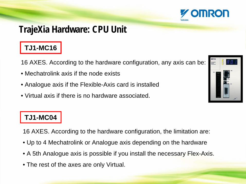
TrajeXia Hardware: CPU Unit
TJ1-MC16
TJ1-MC04
16 AXES. According to the hardware configuration, any axis can be:
• Mechatrolink axis if the node exists
• Analogue axis if the Flexible-Axis card is installed
• Virtual axis if there is no hardware associated.
16 AXES. According to the hardware configuration, the limitation are:
• Up to 4 Mechatrolink or Analogue axis depending on the hardware
• A 5th Analogue axis is possible if you install the necessary Flex-Axis.
• The rest of the axes are only Virtual.
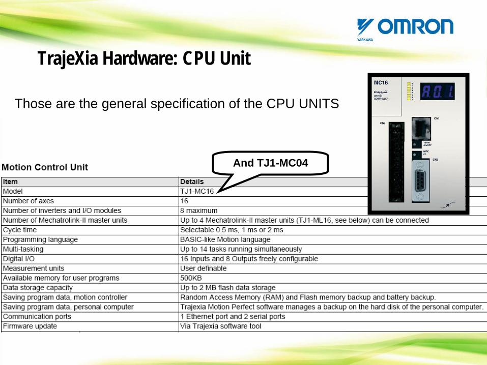
TrajeXia Hardware: CPU Unit
And TJ1-MC04
Those are the general specification of the CPU UNITS
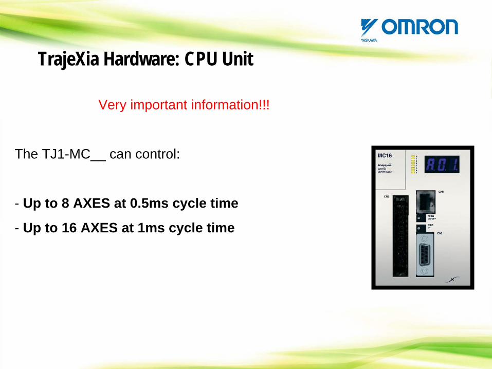
TrajeXia Hardware: CPU Unit
Very important information!!!
The TJ1-MC__ can control:
- Up to 8 AXES at 0.5ms cycle time
- Up to 16 AXES at 1ms cycle time
TrajeXia Hardware: CPU Unit
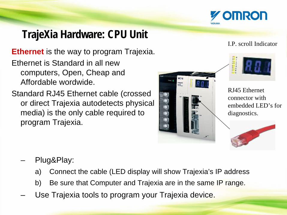
Ethernet is the way to program Trajexia.Ethernet is Standard in all new
computers, Open, Cheap and Affordable wordwide.
Standard RJ45 Ethernet cable (crossed or direct Trajexia autodetects physical media) is the only cable required to program Trajexia.
I.P. scroll Indicator
RJ45 Ethernet connector with embedded LED’s for diagnostics.
– Plug&Play: a) Connect the cable (LED display will show Trajexia’s IP addressb) Be sure that Computer and Trajexia are in the same IP range.
– Use Trajexia tools to program your Trajexia device.
TrajeXia Hardware: CPU Unit
TrajeXia Hardware: CPU Unit
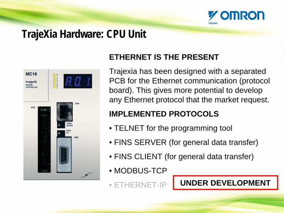
ETHERNET IS THE PRESENT
Trajexia has been designed with a separated PCB for the Ethernet communication (protocol board). This gives more potential to develop any Ethernet protocol that the market request.
IMPLEMENTED PROTOCOLS
• TELNET for the programming tool
• FINS SERVER (for general data transfer)
• FINS CLIENT (for general data transfer)
• MODBUS-TCP
• ETHERNET-IP UNDER DEVELOPMENT
TrajeXia Hardware: CPU Unit
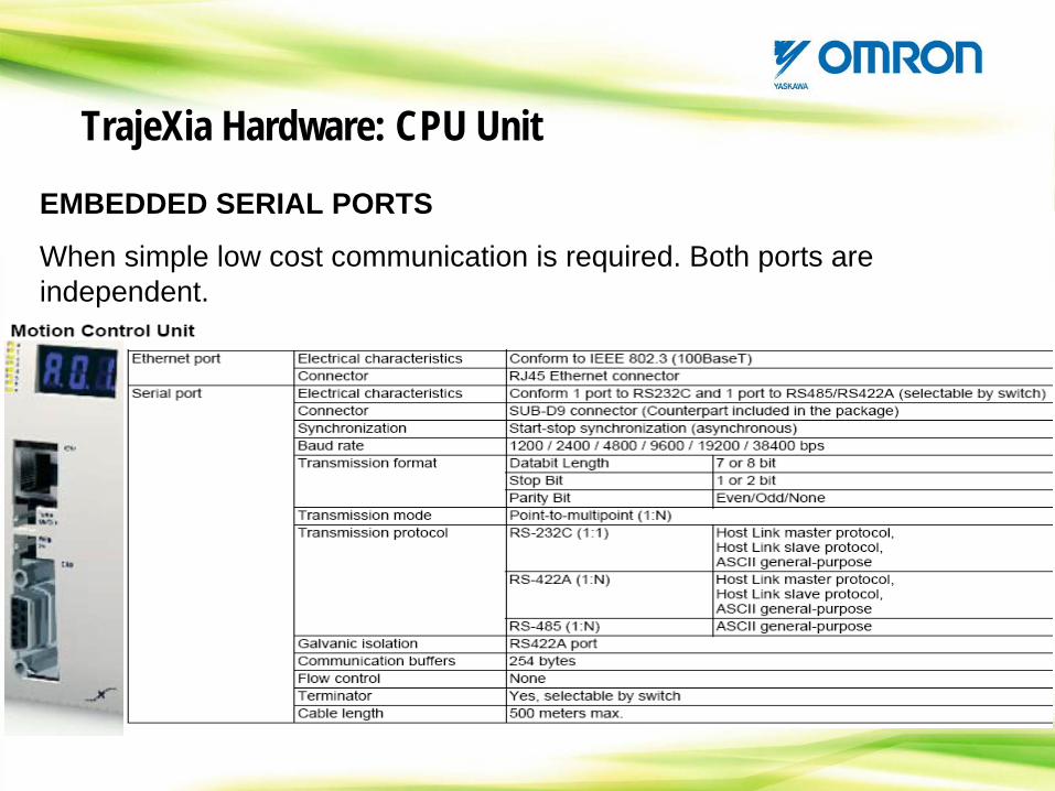
EMBEDDED SERIAL PORTS
When simple low cost communication is required. Both ports are independent.
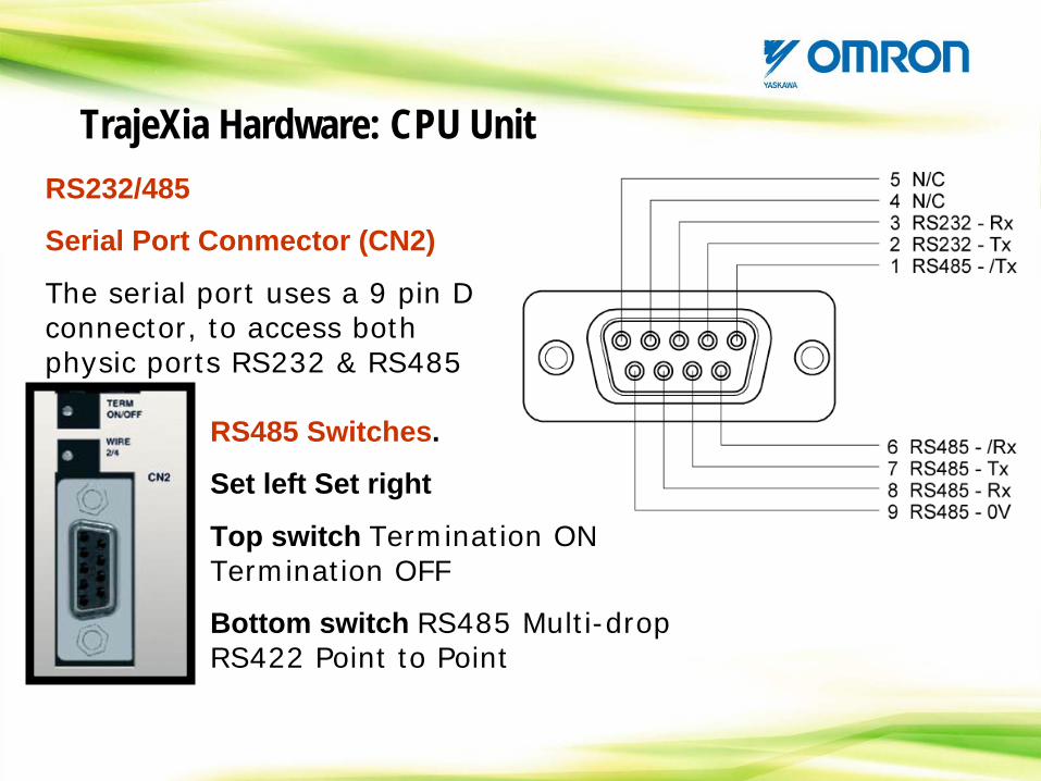
RS232/485
Serial Port Conmector (CN2)
The serial port uses a 9 pin D connector, to access both physic ports RS232 & RS485
RS485 Switches.
Set left Set right
Top switch Termination ON Termination OFF
Bottom switch RS485 Multi-drop RS422 Point to Point
TrajeXia Hardware: CPU Unit
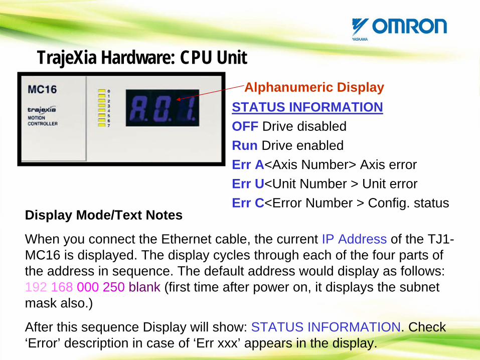
Alphanumeric Display
Display Mode/Text Notes
When you connect the Ethernet cable, the current IP Address of the TJ1- MC16 is displayed. The display cycles through each of the four parts of the address in sequence. The default address would display as follows: 192 168 000 250 blank (first time after power on, it displays the subnet mask also.)
After this sequence Display will show: STATUS INFORMATION. Check ‘Error’ description in case of ‘Err xxx’ appears in the display.
STATUS INFORMATIONOFF Drive disabledRun Drive enabledErr A<Axis Number> Axis errorErr U<Unit Number > Unit errorErr C<Error Number > Config. status
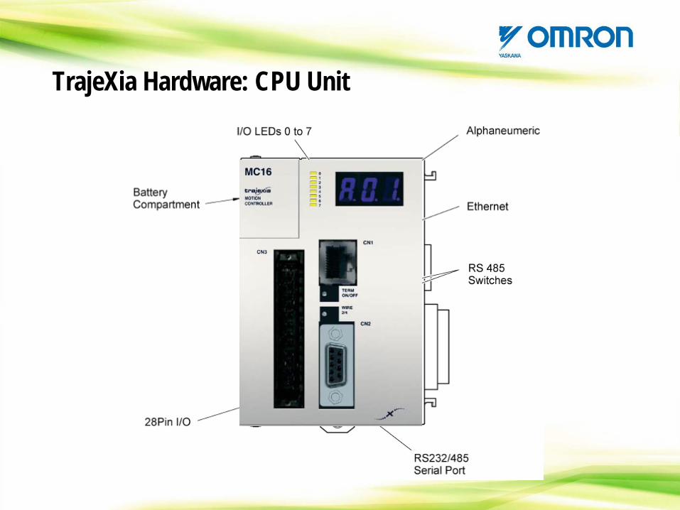
TrajeXia Hardware: CPU Unit
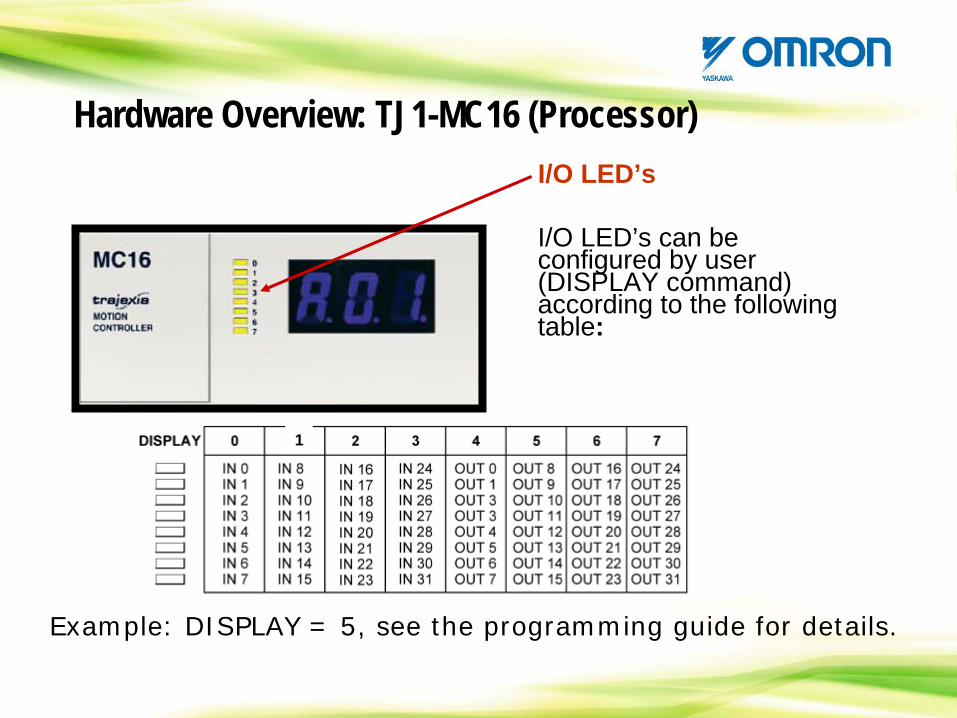
Hardware Overview: TJ1-MC16 (Processor)I/O LED’s
I/O LED’s can be configured by user (DISPLAY command) according to the following table:
Example: DISPLAY = 5, see the programming guide for details.
1

Backup battery
CJ1W-BAT01
Same model than in the PLC’s
The backup battery keeps- Programs- Global variables
Programs and Global variables can be stored in EEPROM memory also for permanent storage (Recommended for finished applications).
TrajeXia Hardware: CPU Unit
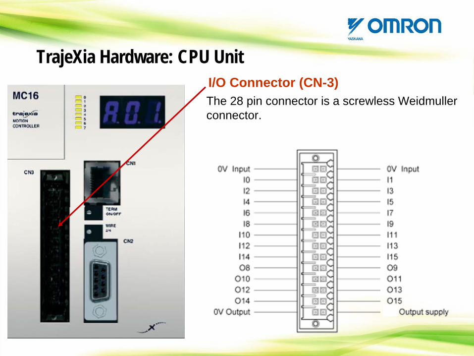
I/O Connector (CN-3)The 28 pin connector is a screwless Weidmuller connector.
TrajeXia Hardware: CPU Unit
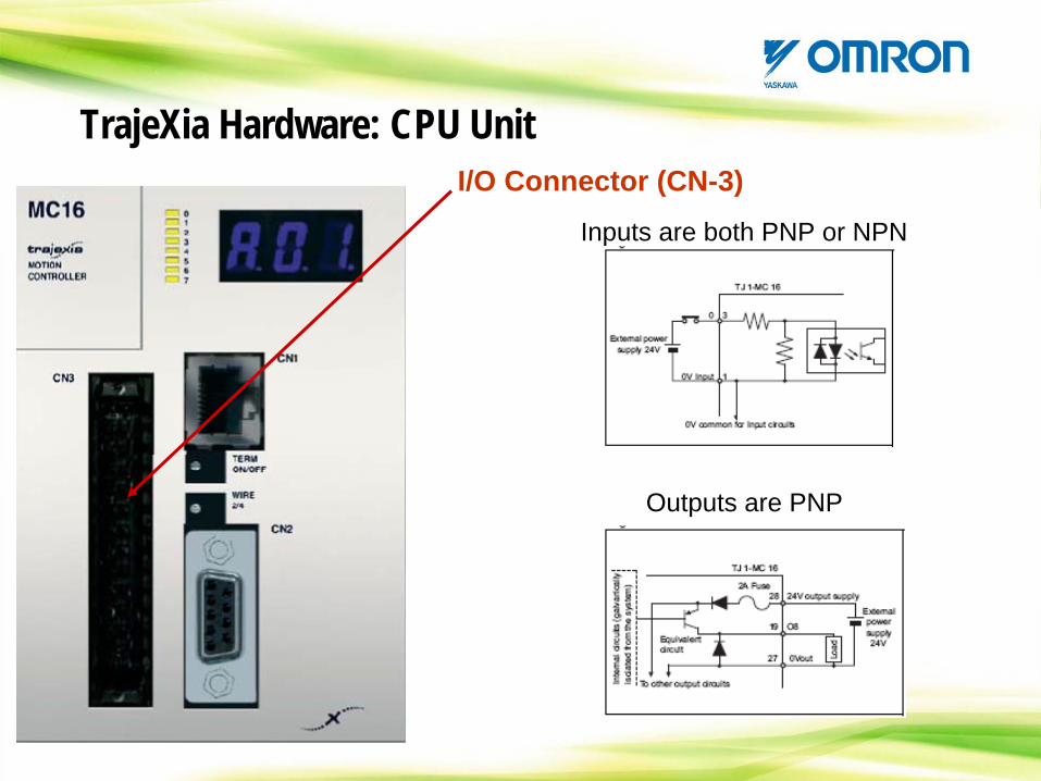
I/O Connector (CN-3)Inputs are both PNP or NPN
TrajeXia Hardware: CPU Unit
Outputs are PNP
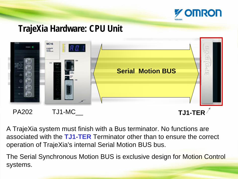
PA202 TJ1-MC__ TJ1-TER
Serial Motion BUS
A TrajeXia system must finish with a Bus terminator. No functions are associated with the TJ1-TER Terminator other than to ensure the correct operation of TrajeXia's internal Serial Motion BUS bus.
The Serial Synchronous Motion BUS is exclusive design for Motion Control systems.
TrajeXia Hardware: CPU Unit
FROM THE BOX:
When you order a TJ1-MC__ In the box it is included the next hardware:
- TJ1-MC__ Unit
- DB-9 male connector
- IO connector
- TJ1-TER
- White clip (to substitute the Yellow one in the PSU)
- 2 x Metal DIN rail clip.
TrajeXia Hardware: CPU Unit
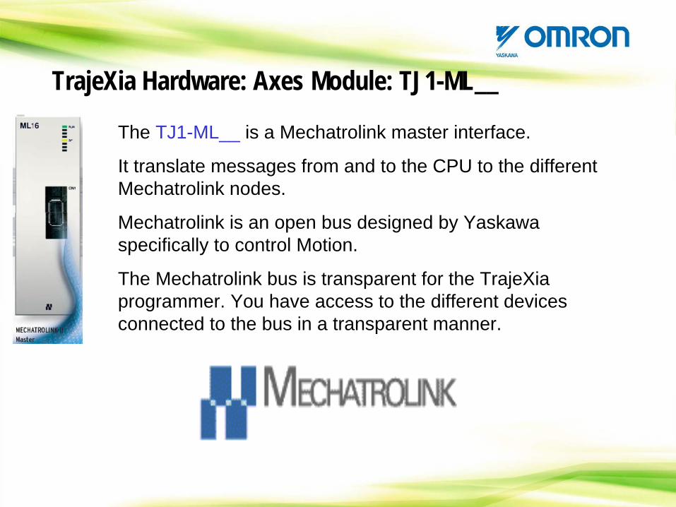
The TJ1-ML__ is a Mechatrolink master interface.
It translate messages from and to the CPU to the different Mechatrolink nodes.
Mechatrolink is an open bus designed by Yaskawa specifically to control Motion.
The Mechatrolink bus is transparent for the TrajeXia programmer. You have access to the different devices connected to the bus in a transparent manner.
TrajeXia Hardware: Axes Module: TJ1-ML__
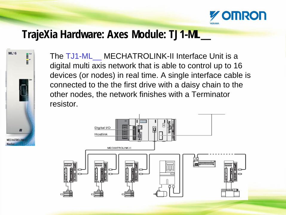
The TJ1-ML__ MECHATROLINK-II Interface Unit is a digital multi axis network that is able to control up to 16 devices (or nodes) in real time. A single interface cable is connected to the the first drive with a daisy chain to the other nodes, the network finishes with a Terminator resistor.
TrajeXia Hardware: Axes Module: TJ1-ML__
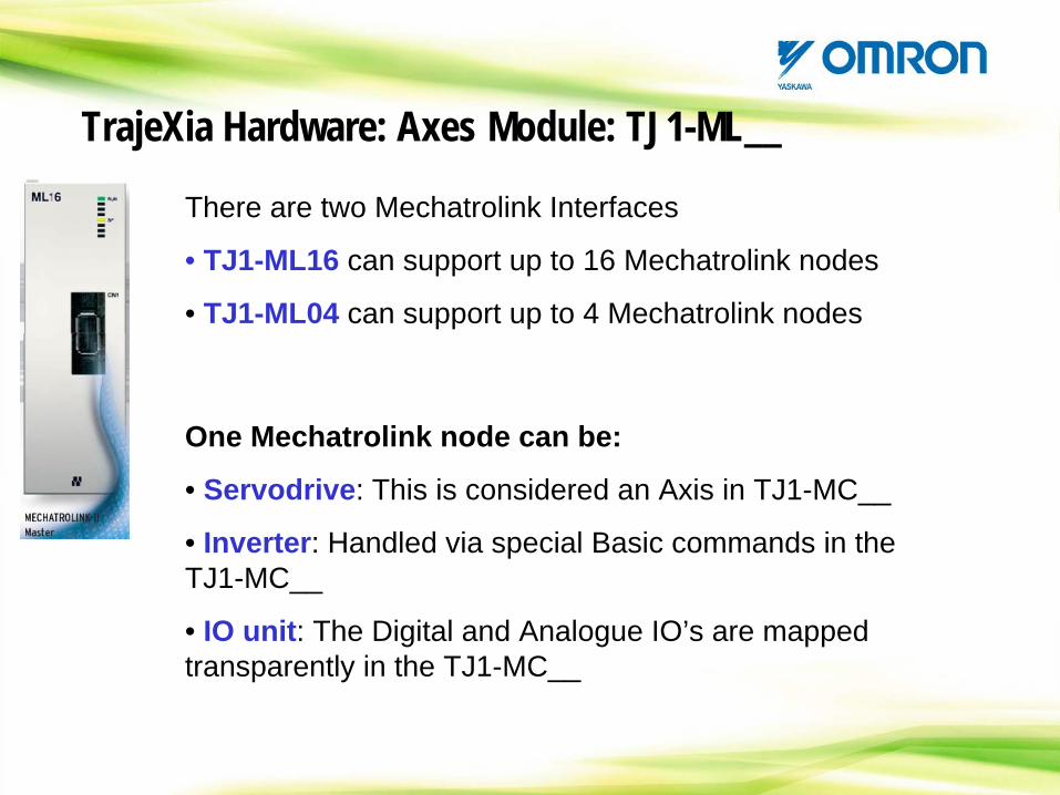
There are two Mechatrolink Interfaces
• TJ1-ML16 can support up to 16 Mechatrolink nodes
• TJ1-ML04 can support up to 4 Mechatrolink nodes
TrajeXia Hardware: Axes Module: TJ1-ML__
One Mechatrolink node can be:
• Servodrive: This is considered an Axis in TJ1-MC__
• Inverter: Handled via special Basic commands in the TJ1-MC__
• IO unit: The Digital and Analogue IO’s are mapped transparently in the TJ1-MC__
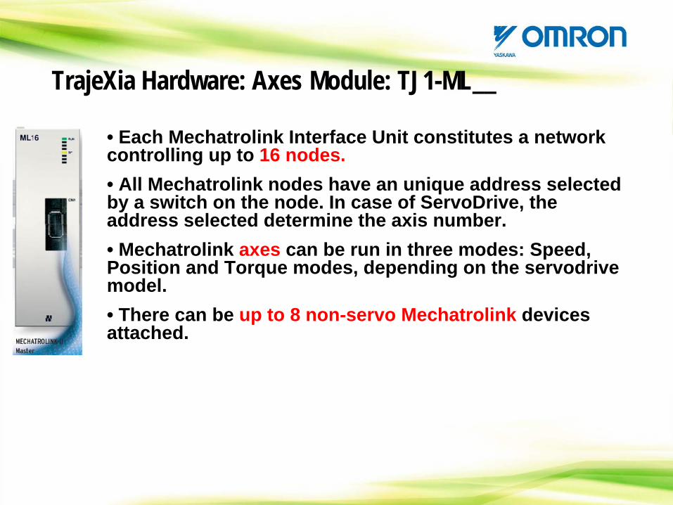
• Each Mechatrolink Interface Unit constitutes a network controlling up to 16 nodes.• All Mechatrolink nodes have an unique address selected by a switch on the node. In case of ServoDrive, the address selected determine the axis number.• Mechatrolink axes can be run in three modes: Speed, Position and Torque modes, depending on the servodrive model.• There can be up to 8 non-servo Mechatrolink devices attached.
TrajeXia Hardware: Axes Module: TJ1-ML__
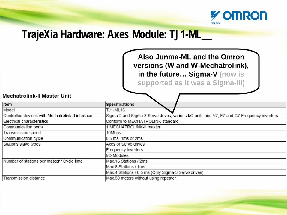
Also Junma-ML and the Omron versions (W and W-Mechatrolink),
in the future… Sigma-V (now is supported as it was a Sigma-III)
TrajeXia Hardware: Axes Module: TJ1-ML__
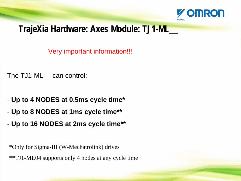
Very important information!!!
The TJ1-ML__ can control:
- Up to 4 NODES at 0.5ms cycle time*
- Up to 8 NODES at 1ms cycle time**
- Up to 16 NODES at 2ms cycle time**
TrajeXia Hardware: Axes Module: TJ1-ML__
*Only for Sigma-III (W-Mechatrolink) drives
**TJ1-ML04 supports only 4 nodes at any cycle time
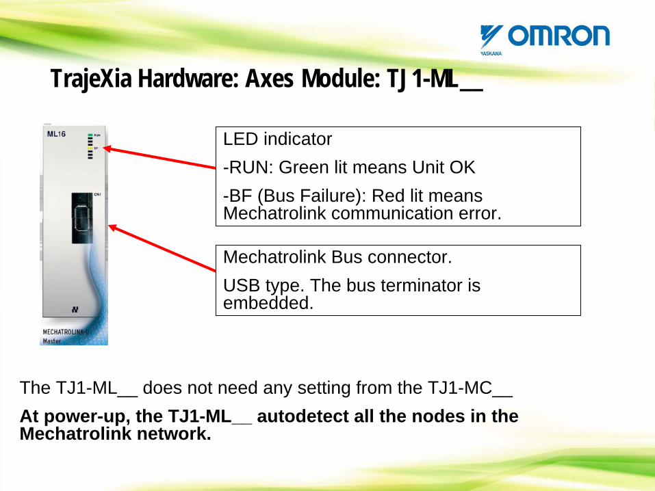
LED indicator-RUN: Green lit means Unit OK-BF (Bus Failure): Red lit means Mechatrolink communication error.
TrajeXia Hardware: Axes Module: TJ1-ML__
Mechatrolink Bus connector.USB type. The bus terminator is embedded.
The TJ1-ML__ does not need any setting from the TJ1-MC__At power-up, the TJ1-ML__ autodetect all the nodes in the Mechatrolink network.
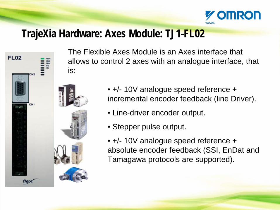
TrajeXia Hardware: Axes Module: TJ1-FL02The Flexible Axes Module is an Axes interface that allows to control 2 axes with an analogue interface, that is:
• +/- 10V analogue speed reference + incremental encoder feedback (line Driver).
• Line-driver encoder output.
• Stepper pulse output.
• +/- 10V analogue speed reference + absolute encoder feedback (SSI, EnDat and Tamagawa protocols are supported).
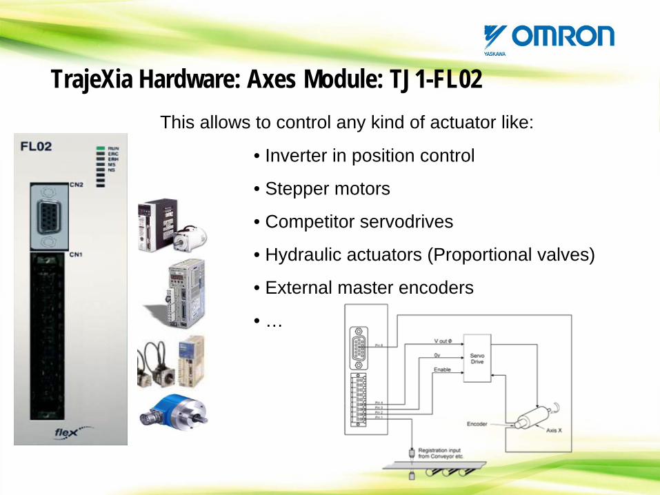
TrajeXia Hardware: Axes Module: TJ1-FL02This allows to control any kind of actuator like:
• Inverter in position control
• Stepper motors
• Competitor servodrives
• Hydraulic actuators (Proportional valves)
• External master encoders
• …
TrajeXia Hardware: Axes Module: TJ1-FL02
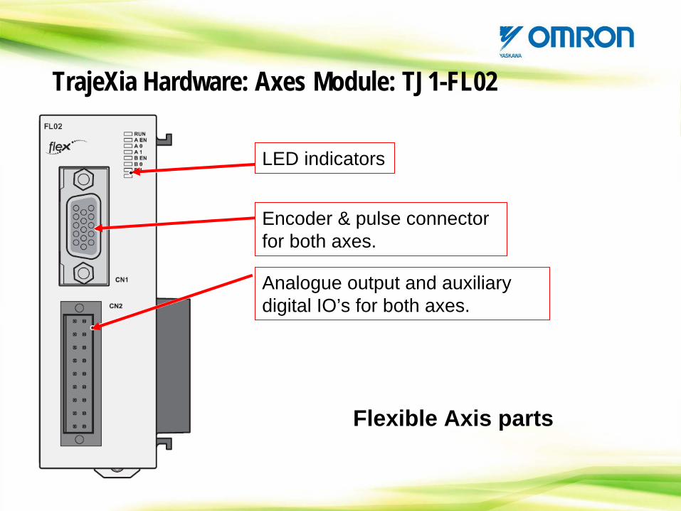
Flexible Axis parts
LED indicators
Encoder & pulse connector for both axes.
Analogue output and auxiliary digital IO’s for both axes.
TrajeXia Hardware: Axes Module: TJ1-FL02
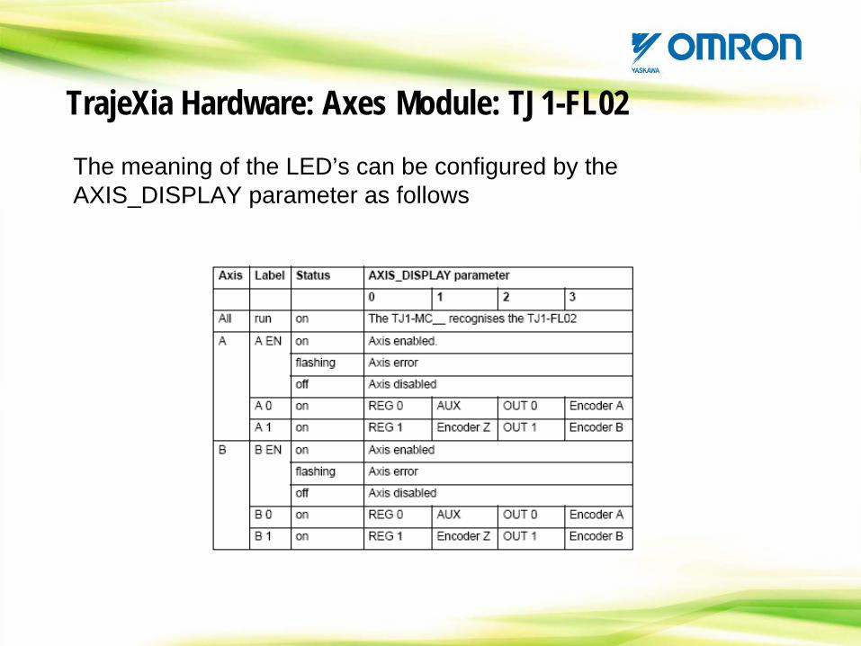
The meaning of the LED’s can be configured by the AXIS_DISPLAY parameter as follows
TrajeXia Hardware: Axes Module: TJ1-FL02
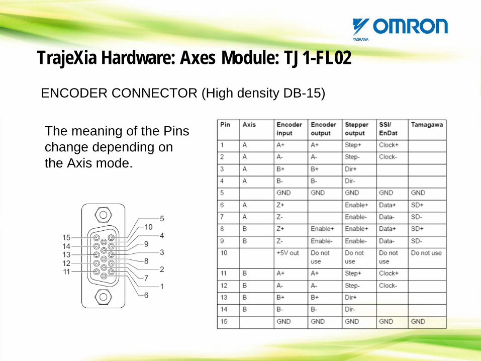
ENCODER CONNECTOR (High density DB-15)
The meaning of the Pins change depending on the Axis mode.
TrajeXia Hardware: Axes Module: TJ1-FL02
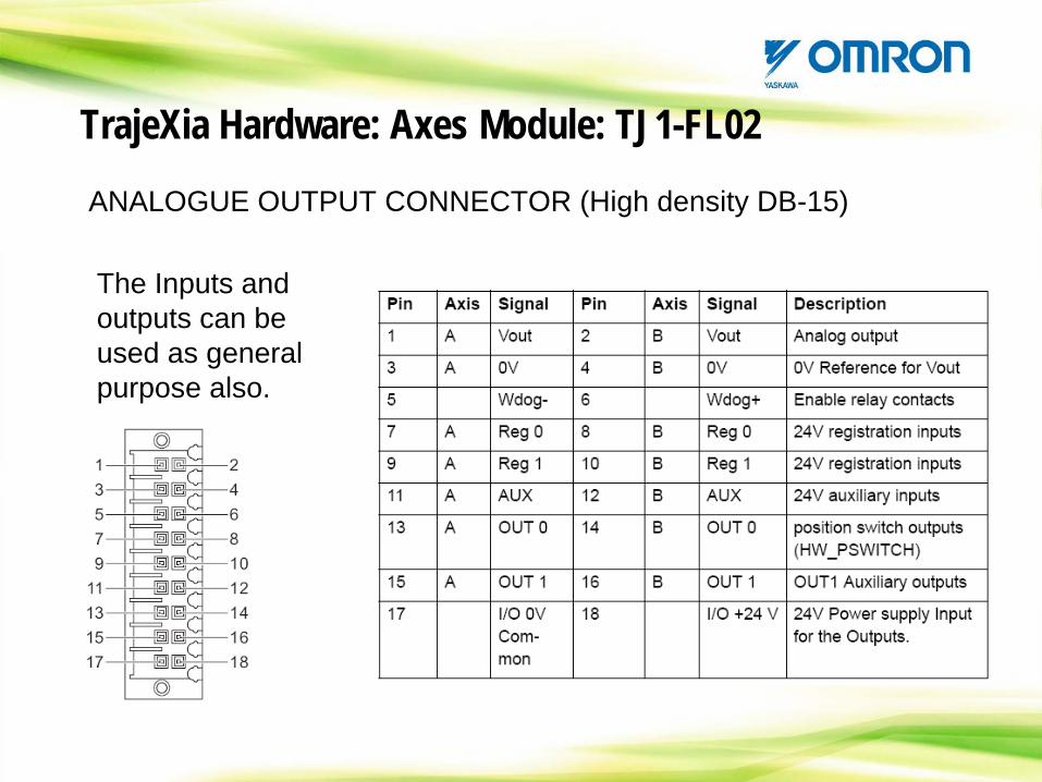
ANALOGUE OUTPUT CONNECTOR (High density DB-15)
The Inputs and outputs can be used as general purpose also.
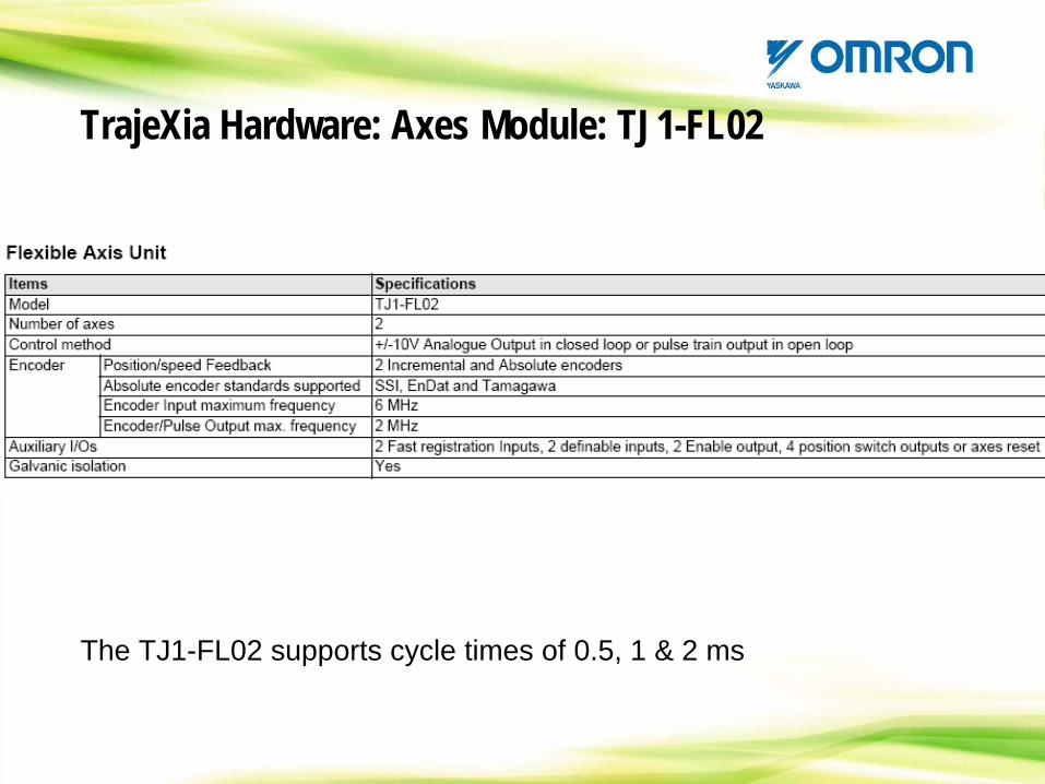
The TJ1-FL02 supports cycle times of 0.5, 1 & 2 ms
TrajeXia Hardware: Axes Module: TJ1-FL02
TrajeXia Hardware: Mechatrolink bus
MECHATROLINK-II is an open communication bus specially designed for motion control.
Although the bus is transparent to the user (you do not have to take care about how it is working) it is good to know a few data.
One bus for motion must be:
- Short message.
- Very quick.
- Deterministic.
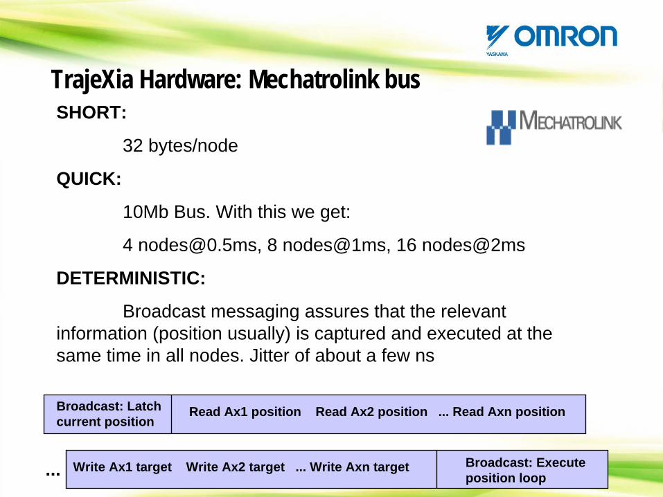
TrajeXia Hardware: Mechatrolink busSHORT:
32 bytes/node
QUICK:
10Mb Bus. With this we get:
4 [email protected], 8 nodes@1ms, 16 nodes@2ms
DETERMINISTIC:
Broadcast messaging assures that the relevant information (position usually) is captured and executed at the same time in all nodes. Jitter of about a few ns
Broadcast: Latch current position
Read Ax1 position Read Ax2 position ... Read Axn position
... Write Ax1 target Write Ax2 target ... Write Axn target Broadcast: Execute position loop
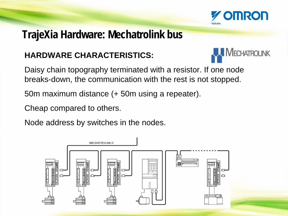
TrajeXia Hardware: Mechatrolink busHARDWARE CHARACTERISTICS:
Daisy chain topography terminated with a resistor. If one node breaks-down, the communication with the rest is not stopped.
50m maximum distance (+ 50m using a repeater).
Cheap compared to others.
Node address by switches in the nodes.
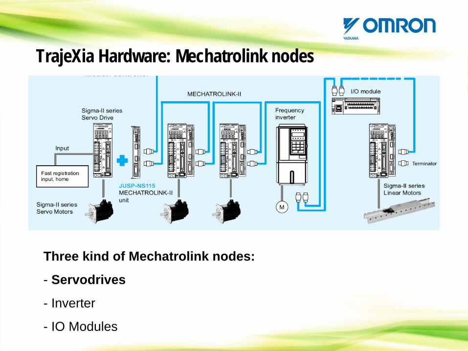
TrajeXia Hardware: Mechatrolink nodes
Three kind of Mechatrolink nodes:
- Servodrives
- Inverter
- IO Modules
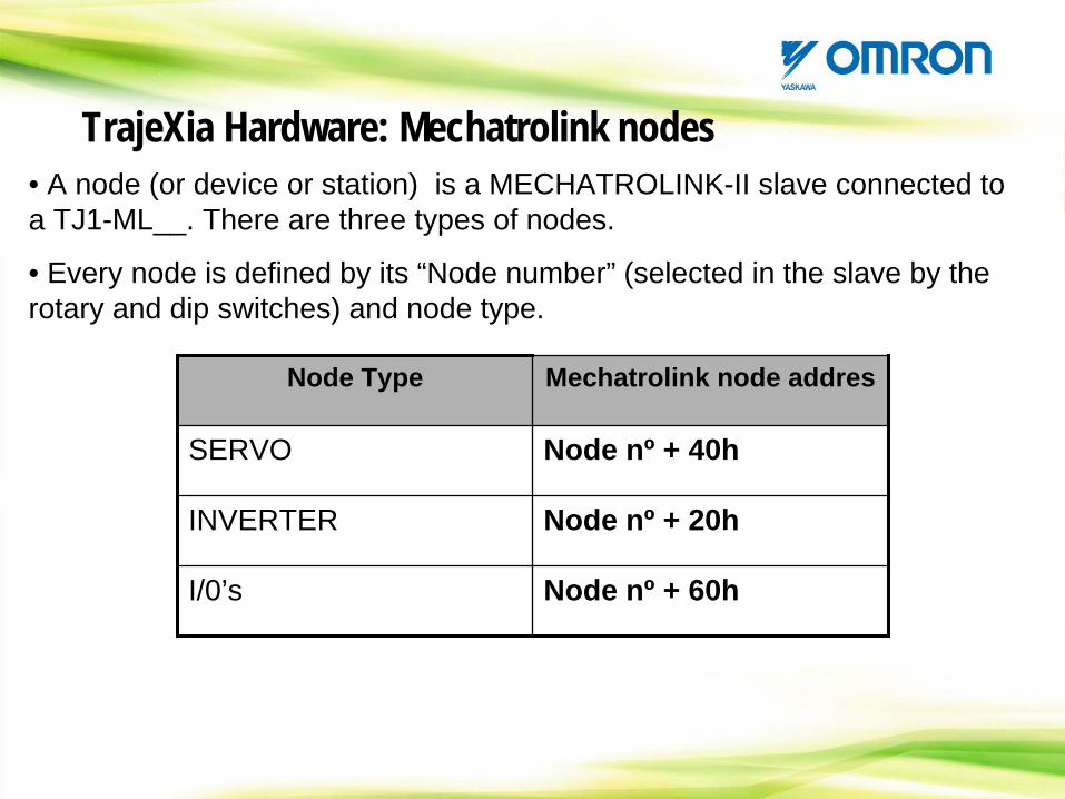
• A node (or device or station) is a MECHATROLINK-II slave connected to a TJ1-ML__. There are three types of nodes.
• Every node is defined by its “Node number” (selected in the slave by the rotary and dip switches) and node type.
Node Type Mechatrolink node addres
SERVO Node nº + 40h
INVERTER Node nº + 20h
I/0’s Node nº + 60h
TrajeXia Hardware: Mechatrolink nodes
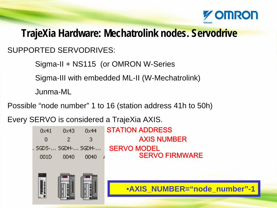
SUPPORTED SERVODRIVES:
Sigma-II + NS115 (or OMRON W-Series
Sigma-III with embedded ML-II (W-Mechatrolink)
Junma-ML
Possible “node number” 1 to 16 (station address 41h to 50h)
Every SERVO is considered a TrajeXia AXIS. STATION
ADDRESSAXIS NUMBER
SERVO MODELSERVO FIRMWARE
•AXIS_NUMBER=“node_number”-1
TrajeXia Hardware: Mechatrolink nodes. Servodrive
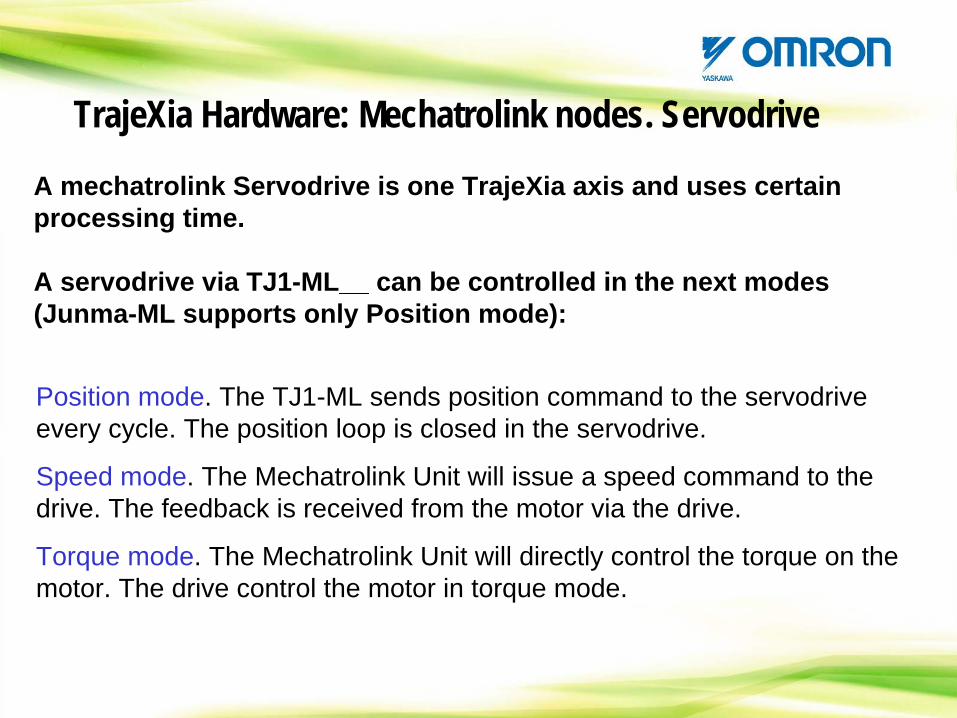
Position mode. The TJ1-ML sends position command to the servodrive every cycle. The position loop is closed in the servodrive.
Speed mode. The Mechatrolink Unit will issue a speed command to the drive. The feedback is received from the motor via the drive.
Torque mode. The Mechatrolink Unit will directly control the torque on the motor. The drive control the motor in torque mode.
A mechatrolink Servodrive is one TrajeXia axis and uses certain processing time.
A servodrive via TJ1-ML__ can be controlled in the next modes (Junma-ML supports only Position mode):
TrajeXia Hardware: Mechatrolink nodes. Servodrive
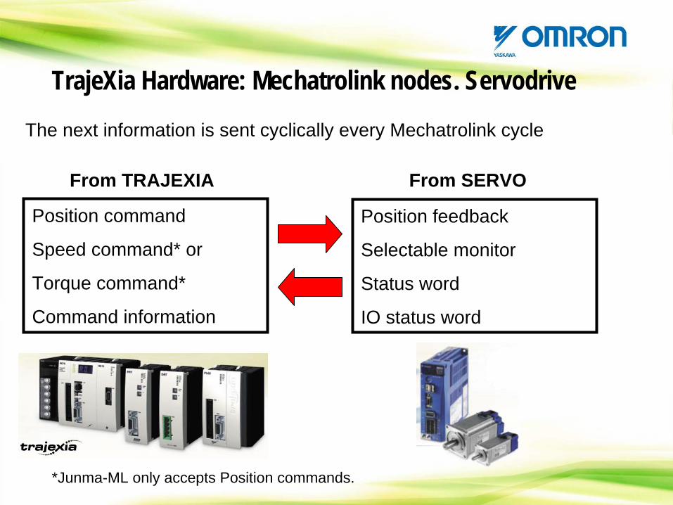
The next information is sent cyclically every Mechatrolink cycle
TrajeXia Hardware: Mechatrolink nodes. Servodrive
Position command
Speed command* or
Torque command*
Command information
Position feedback
Selectable monitor
Status word
IO status word
From TRAJEXIA From SERVO
*Junma-ML only accepts Position commands.
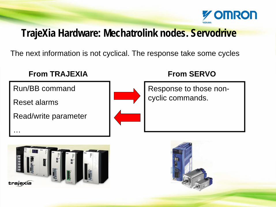
The next information is not cyclical. The response take some cycles
TrajeXia Hardware: Mechatrolink nodes. Servodrive
Run/BB command
Reset alarms
Read/write parameter
…
Response to those non- cyclic commands.
From TRAJEXIA From SERVO
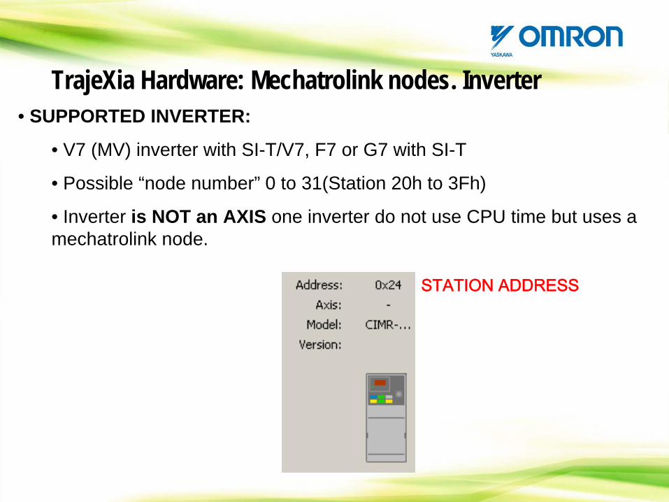
• SUPPORTED INVERTER:
• V7 (MV) inverter with SI-T/V7, F7 or G7 with SI-T
• Possible “node number” 0 to 31(Station 20h to 3Fh)
• Inverter is NOT an AXIS one inverter do not use CPU time but uses a mechatrolink node.
TrajeXia Hardware: Mechatrolink nodes. Inverter
STATION
ADDRESS
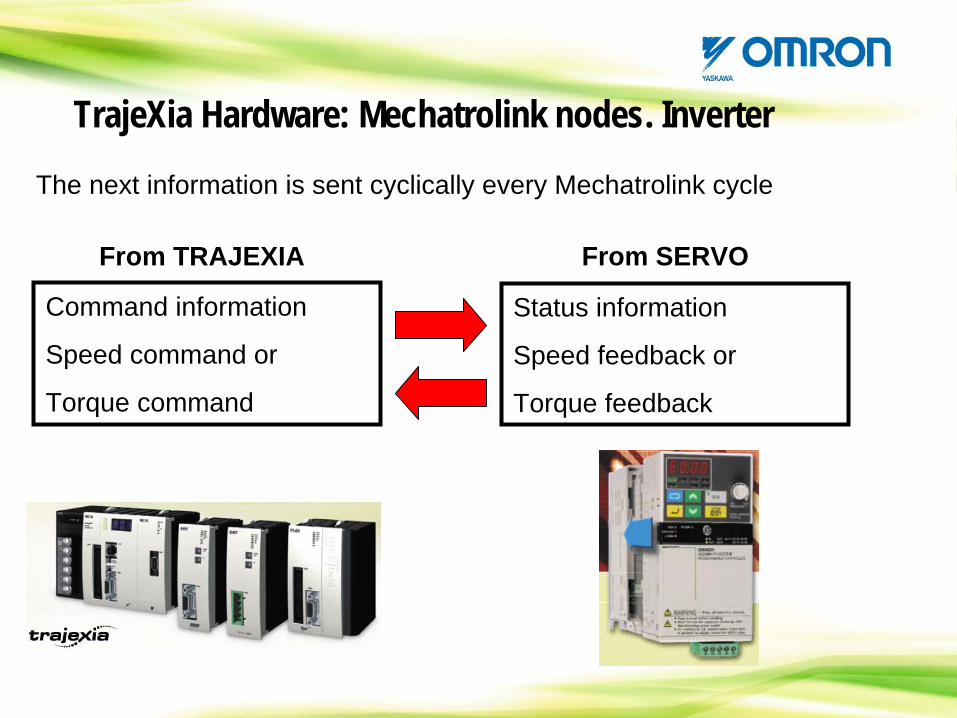
The next information is sent cyclically every Mechatrolink cycle
TrajeXia Hardware: Mechatrolink nodes. Inverter
Command information
Speed command or
Torque command
Status information
Speed feedback or
Torque feedback
From TRAJEXIA From SERVO
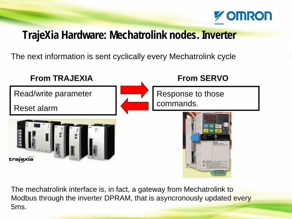
The next information is sent cyclically every Mechatrolink cycle
TrajeXia Hardware: Mechatrolink nodes. Inverter
Read/write parameter
Reset alarm
Response to those commands.
From TRAJEXIA From SERVO
The mechatrolink interface is, in fact, a gateway from Mechatrolink to Modbus through the inverter DPRAM, that is asyncronously updated every 5ms.
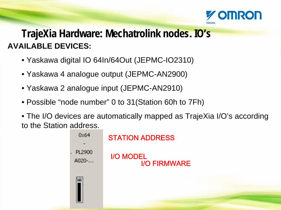
AVAILABLE DEVICES:
• Yaskawa digital IO 64In/64Out (JEPMC-IO2310)
• Yaskawa 4 analogue output (JEPMC-AN2900)
• Yaskawa 2 analogue input (JEPMC-AN2910)
• Possible “node number” 0 to 31(Station 60h to 7Fh)
• The I/O devices are automatically mapped as TrajeXia I/O’s according to the Station address.
STATION ADDRESS
I/O MODELI/O FIRMWARE
TrajeXia Hardware: Mechatrolink nodes. IO’s
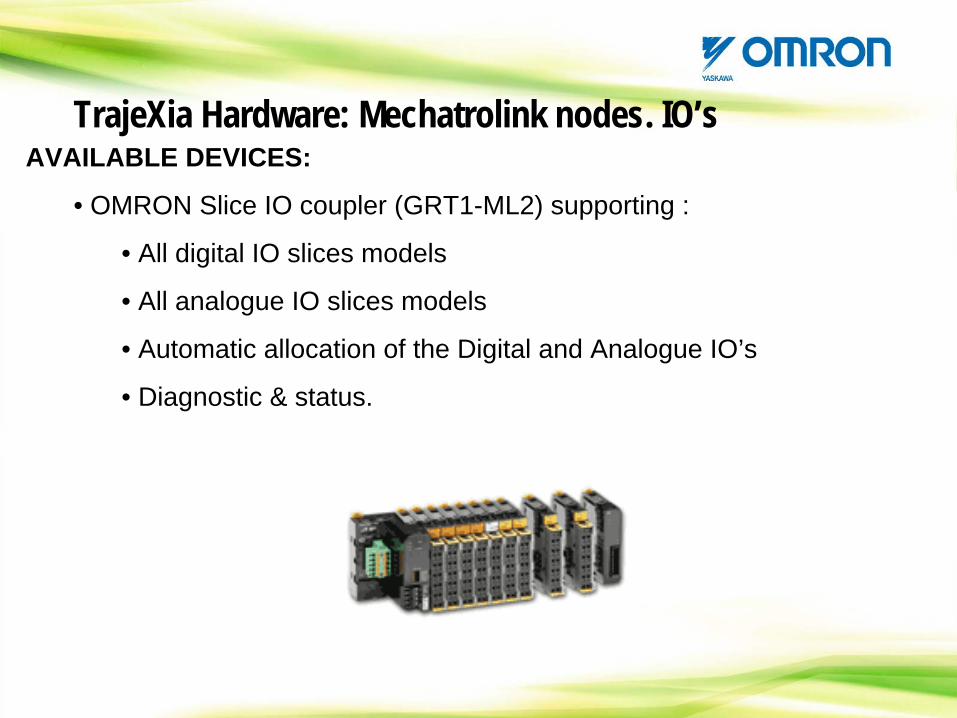
AVAILABLE DEVICES:
• OMRON Slice IO coupler (GRT1-ML2) supporting :
• All digital IO slices models
• All analogue IO slices models
• Automatic allocation of the Digital and Analogue IO’s
• Diagnostic & status.
TrajeXia Hardware: Mechatrolink nodes. IO’s
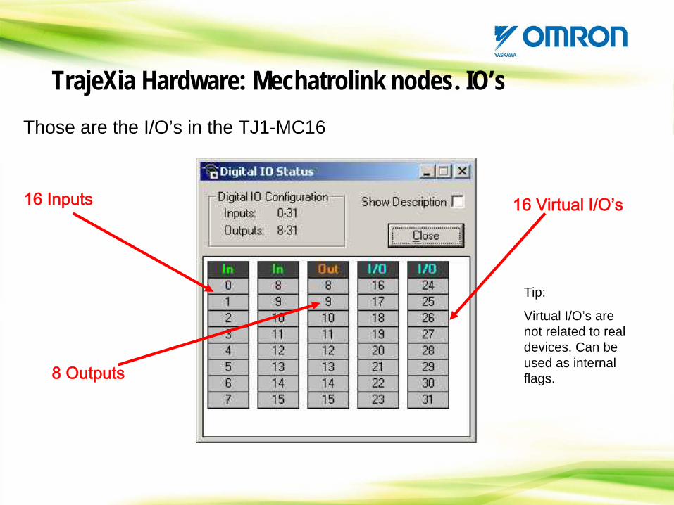
Those are the I/O’s in the TJ1-MC16
16 Inputs
8 Outputs
16 Virtual I/O’s
Tip:
Virtual I/O’s are not related to real devices. Can be used as internal flags.
TrajeXia Hardware: Mechatrolink nodes. IO’s
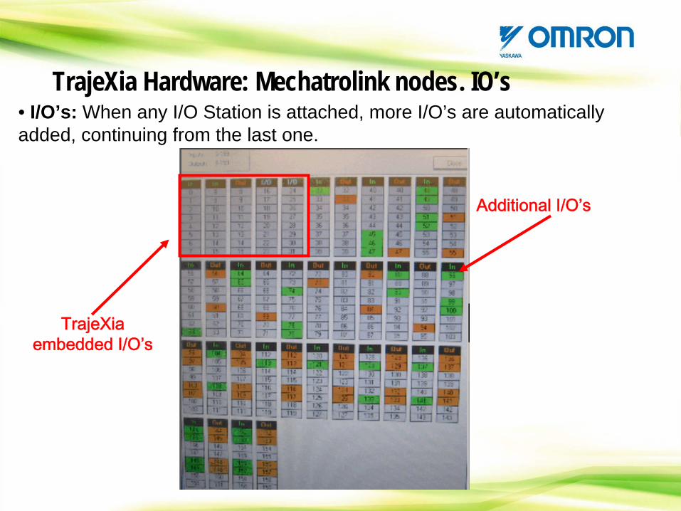
• I/O’s: When any I/O Station is attached, more I/O’s are automatically added, continuing from the last one.
Additional
I/O’s
TrajeXia Hardware: Mechatrolink nodes. IO’s
TrajeXia embedded
I/O’s
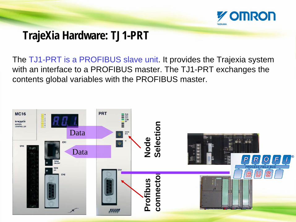
The TJ1-PRT is a PROFIBUS slave unit. It provides the Trajexia system with an interface to a PROFIBUS master. The TJ1-PRT exchanges the contents global variables with the PROFIBUS master.
Nod
e Se
lect
ion
Prof
ibus
conn
ecto
r
Data
Data
TrajeXia Hardware: TJ1-PRT
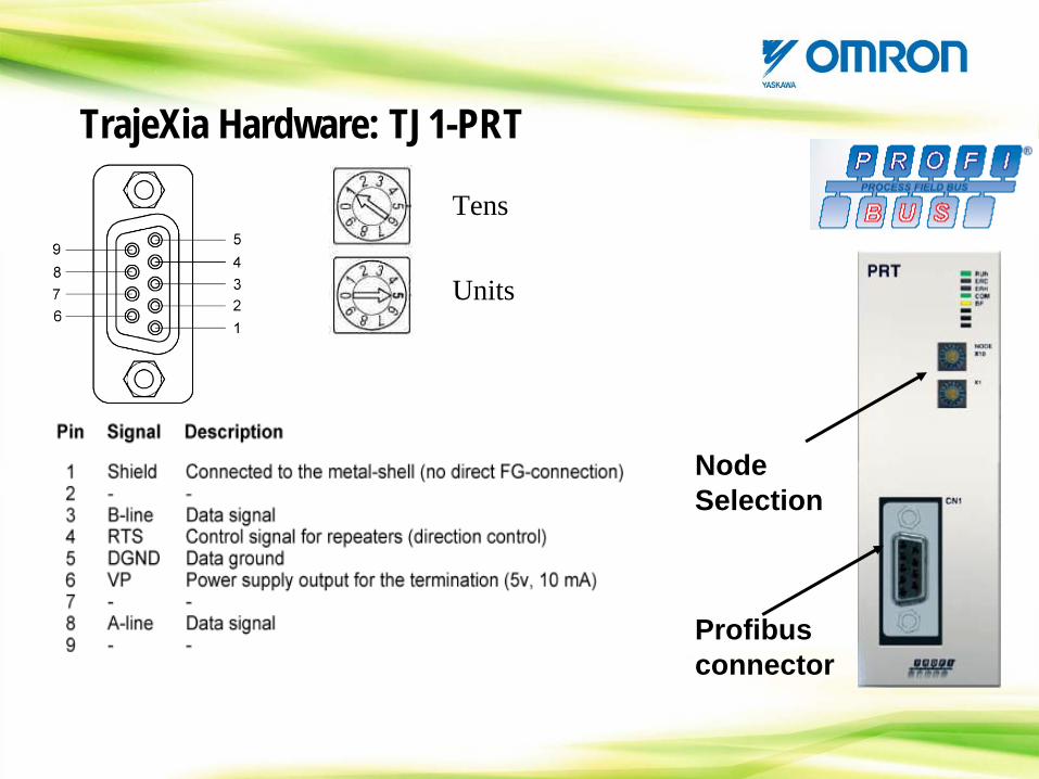
Node Selection
Profibus connector
Units
Tens
TrajeXia Hardware: TJ1-PRT
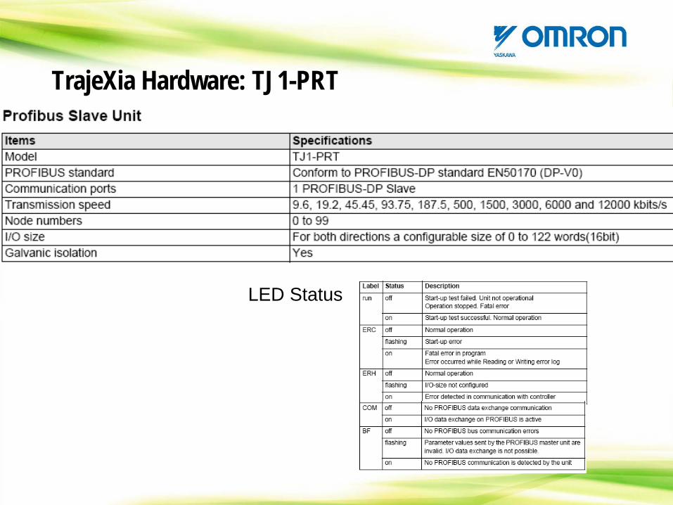
LED Status
TrajeXia Hardware: TJ1-PRT
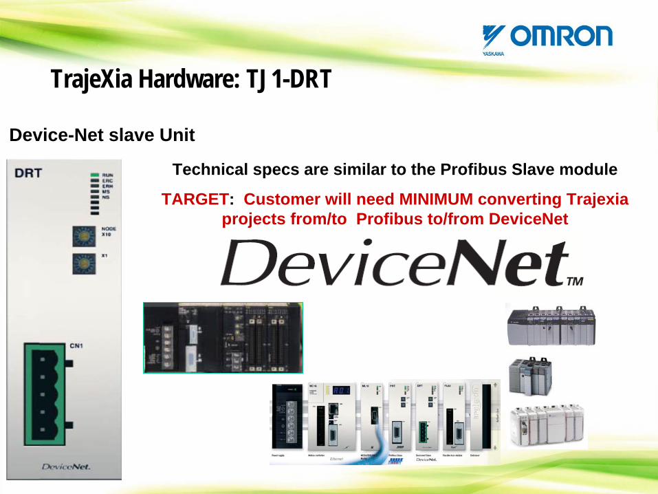
Technical specs are similar to the Profibus Slave module
TARGET: Customer will need MINIMUM converting Trajexia projects from/to Profibus to/from DeviceNet
TrajeXia Hardware: TJ1-DRT
Device-Net slave Unit
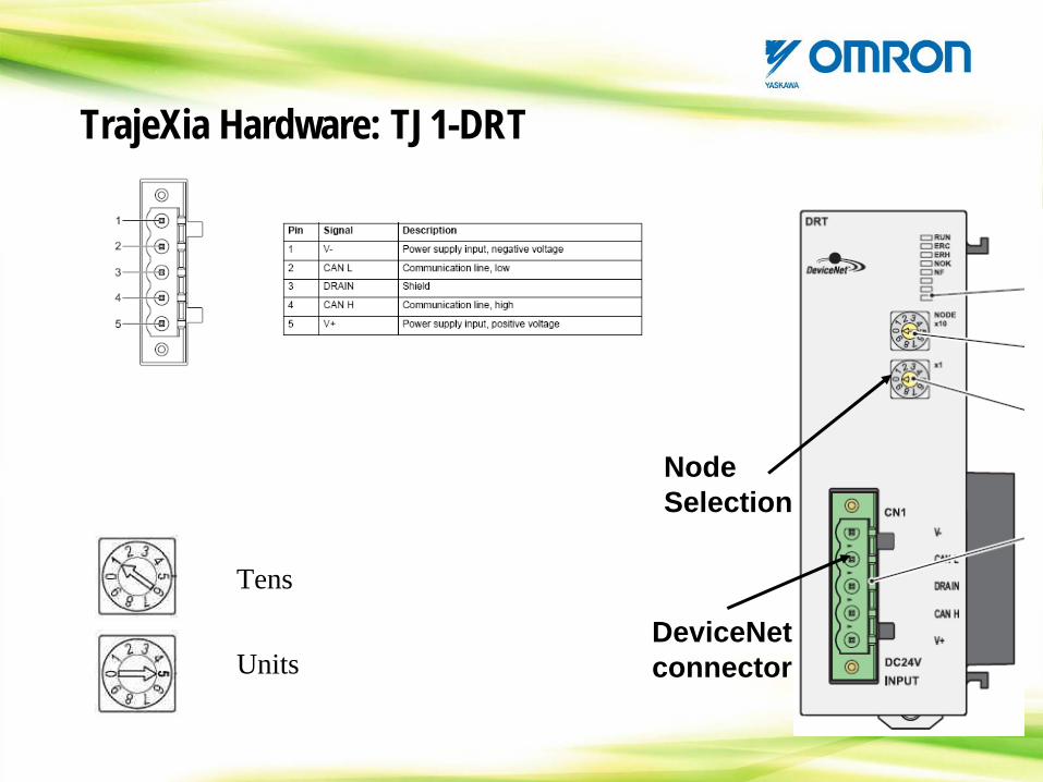
Node Selection
DeviceNet connectorUnits
Tens
TrajeXia Hardware: TJ1-DRT
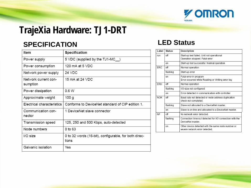
LED StatusTrajeXia Hardware: TJ1-DRT
SPECIFICATION
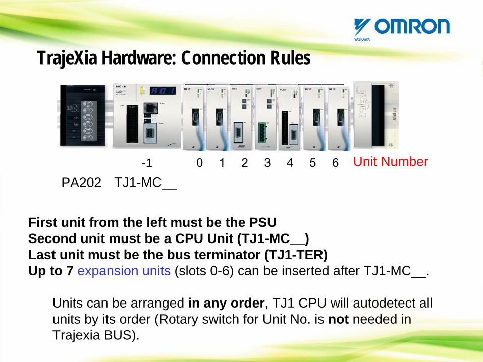
0 1 2 3 4 5 6PA202 TJ1-MC__
First unit from the left must be the PSUSecond unit must be a CPU Unit (TJ1-MC__)Last unit must be the bus terminator (TJ1-TER)Up to 7 expansion units (slots 0-6) can be inserted after TJ1-MC__.
Units can be arranged in any order, TJ1 CPU will autodetect all units by its order (Rotary switch for Unit No. is not needed in Trajexia BUS).
-1
TrajeXia Hardware: Connection Rules
Unit Number
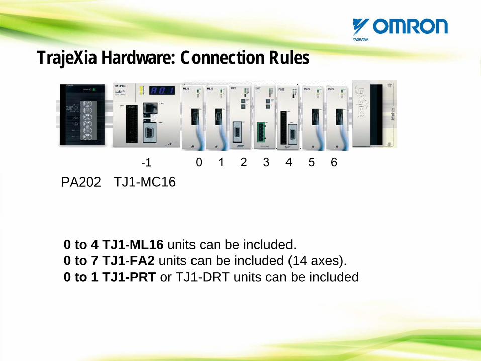
0 1 2 3 4 5 6PA202 TJ1-MC16
-1
TrajeXia Hardware: Connection Rules
0 to 4 TJ1-ML16 units can be included.0 to 7 TJ1-FA2 units can be included (14 axes).0 to 1 TJ1-PRT or TJ1-DRT units can be included
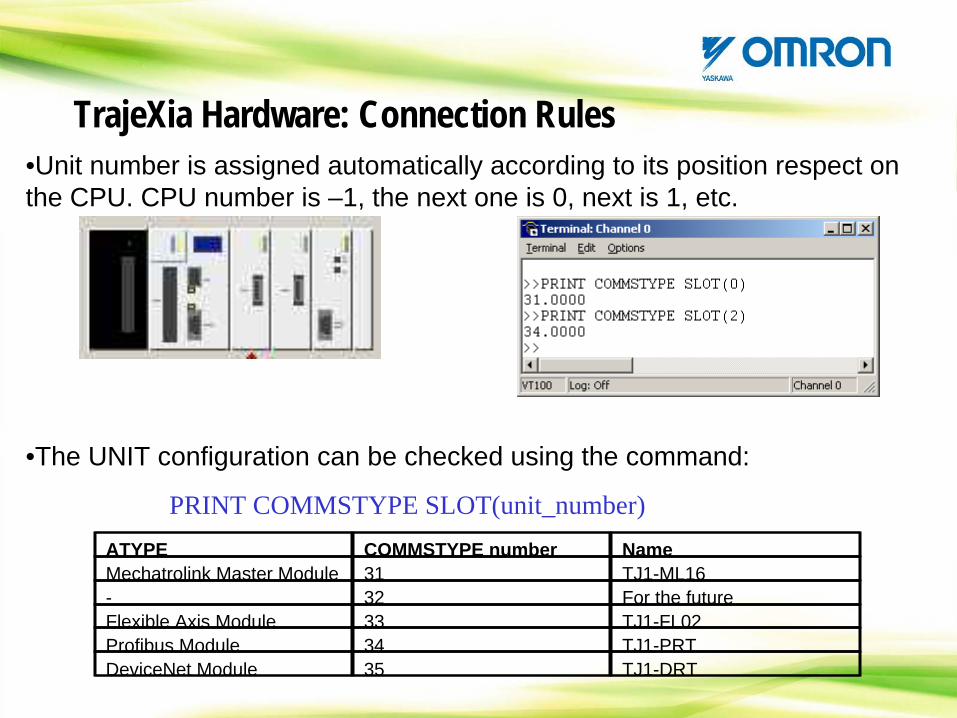
•Unit number is assigned automatically according to its position respect on the CPU. CPU number is –1, the next one is 0, next is 1, etc.
•The UNIT configuration can be checked using the command:
PRINT COMMSTYPE SLOT(unit_number)
TrajeXia Hardware: Connection Rules
ATYPE COMMSTYPE number NameMechatrolink Master Module 31 TJ1-ML16- 32 For the futureFlexible Axis Module 33 TJ1-FL02Profibus Module 34 TJ1-PRTDeviceNet Module 35 TJ1-DRT
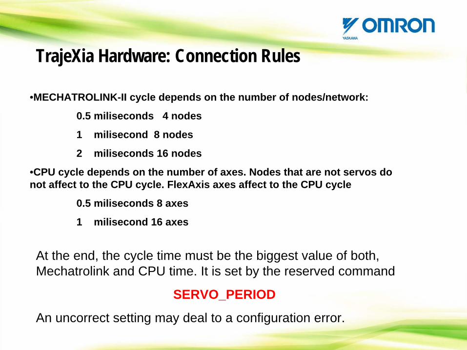
•MECHATROLINK-II cycle depends on the number of nodes/network:
0.5 miliseconds 4 nodes
1 milisecond 8 nodes
2 miliseconds 16 nodes
•CPU cycle depends on the number of axes. Nodes that are not servos do not affect to the CPU cycle. FlexAxis axes affect to the CPU cycle
0.5 miliseconds 8 axes
1 milisecond 16 axes
TrajeXia Hardware: Connection Rules
At the end, the cycle time must be the biggest value of both, Mechatrolink and CPU time. It is set by the reserved command
SERVO_PERIOD
An uncorrect setting may deal to a configuration error.
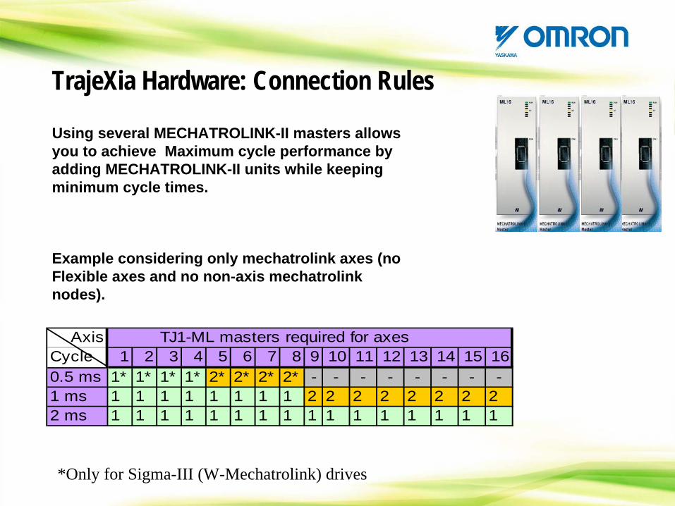
Axis TJ1-ML masters required for axesCycle 1 2 3 4 5 6 7 8 9 10 11 12 13 14 15 160.5 ms 1* 1* 1* 1* 2* 2* 2* 2* - - - - - - - -1 ms 1 1 1 1 1 1 1 1 2 2 2 2 2 2 2 22 ms 1 1 1 1 1 1 1 1 1 1 1 1 1 1 1 1
Using several MECHATROLINK-II masters allows you to achieve Maximum cycle performance by adding MECHATROLINK-II units while keeping minimum cycle times.
*Only for Sigma-III (W-Mechatrolink) drives
TrajeXia Hardware: Connection Rules
Example considering only mechatrolink axes (no Flexible axes and no non-axis mechatrolink nodes).
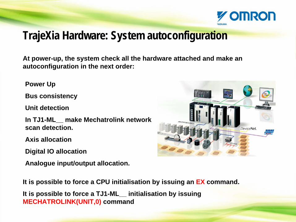
At power-up, the system check all the hardware attached and make an autoconfiguration in the next order:
TrajeXia Hardware: System autoconfiguration
Power Up
Bus consistency
Unit detection
In TJ1-ML__ make Mechatrolink network scan detection.
Axis allocation
Digital IO allocation
Analogue input/output allocation.
It is possible to force a CPU initialisation by issuing an EX command.
It is possible to force a TJ1-ML__ initialisation by issuing MECHATROLINK(UNIT,0) command
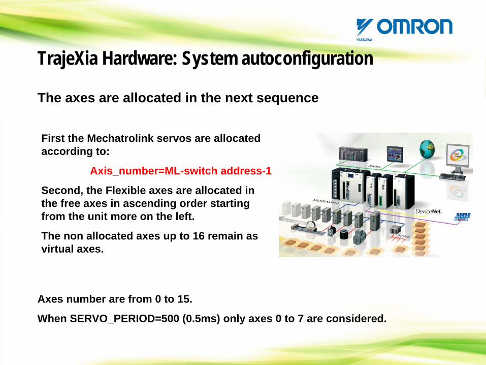
The axes are allocated in the next sequence
TrajeXia Hardware: System autoconfiguration
First the Mechatrolink servos are allocated according to:
Axis_number=ML-switch address-1
Second, the Flexible axes are allocated in the free axes in ascending order starting from the unit more on the left.
The non allocated axes up to 16 remain as virtual axes.
Axes number are from 0 to 15.
When SERVO_PERIOD=500 (0.5ms) only axes 0 to 7 are considered.
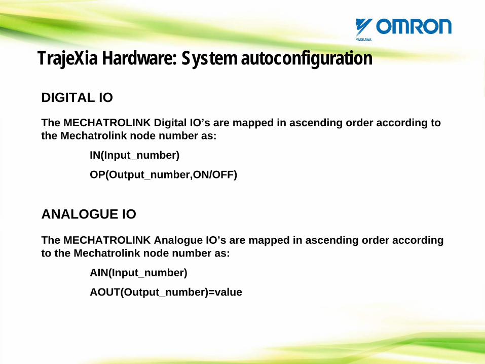
DIGITAL IO
TrajeXia Hardware: System autoconfiguration
The MECHATROLINK Digital IO’s are mapped in ascending order according to the Mechatrolink node number as:
IN(Input_number)
OP(Output_number,ON/OFF)
ANALOGUE IO
The MECHATROLINK Analogue IO’s are mapped in ascending order according to the Mechatrolink node number as:
AIN(Input_number)
AOUT(Output_number)=value
CONTENTS
TrajeXia OverviewHardware and general specification TrajeXia ToolsTrajexia ArchitectureProgramming TrajeXiaHow I do… with TrajeXia?CommunicationTrajeXia success histories
CONTENTS: TrajeXia Tools
-Installing the software-Connecting to TrajeXia-Software tool overview
Trajexia ToolsTrajexia Software Tools include all necessary tools to develop & work with Trajexia in same Installation Software. Stand Alone system is fully supported.
•Motion Perfect 2 (Trajexia Edition).
•Encryptor (Trajexia Edition)
•CX-Server
•CX-Drive (full)
Trajexia ToolsTrajeXia Tools is part of the CX-One software platform.
TrajeXia Tools share the same license with the CX-Drive.
If you have CX-Drive already installed in your computer you do not need a new license.
Trajexia Tools: Installing the softwareHANDS ON
LET’S INSTALL “TrajeXia TOOLS”
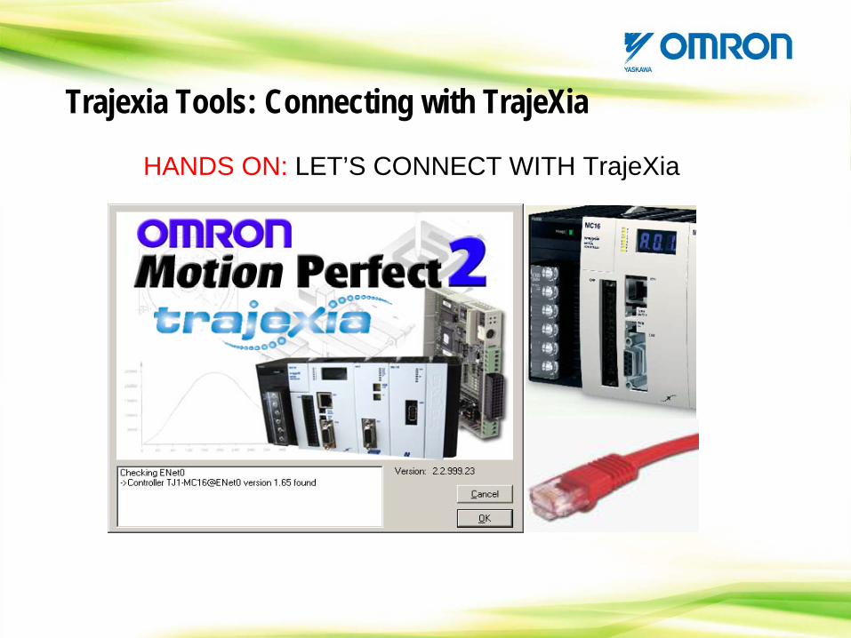
Trajexia Tools: Connecting with TrajeXia
HANDS ON: LET’S CONNECT WITH TrajeXia
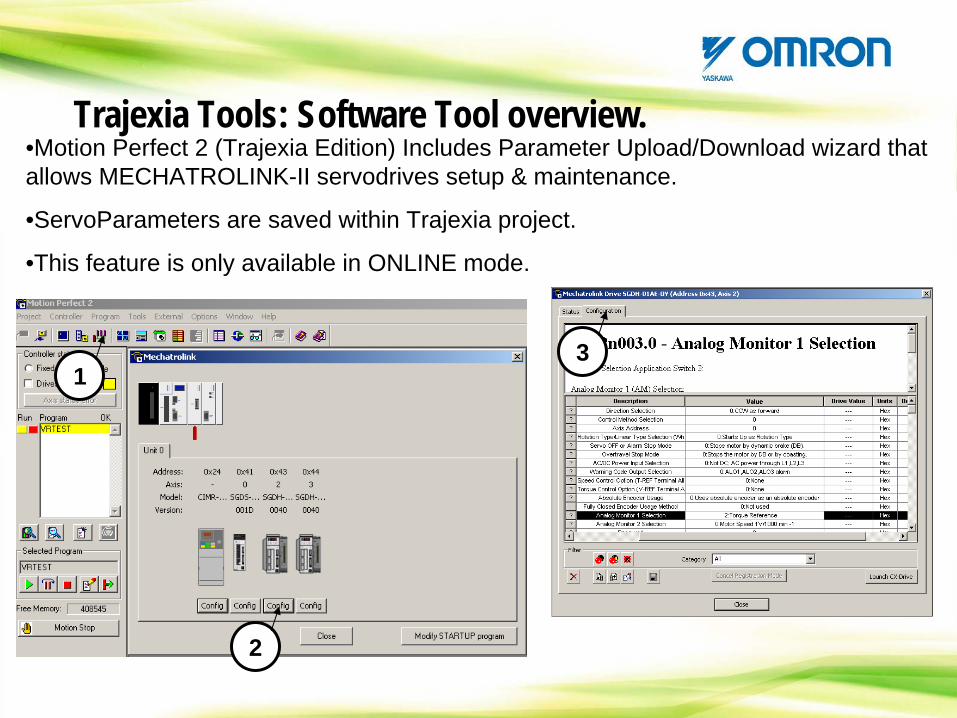
Trajexia Tools: Software Tool overview.•Motion Perfect 2 (Trajexia Edition) Includes Parameter Upload/Download wizard that allows MECHATROLINK-II servodrives setup & maintenance.
•ServoParameters are saved within Trajexia project.
•This feature is only available in ONLINE mode.
1
2
3
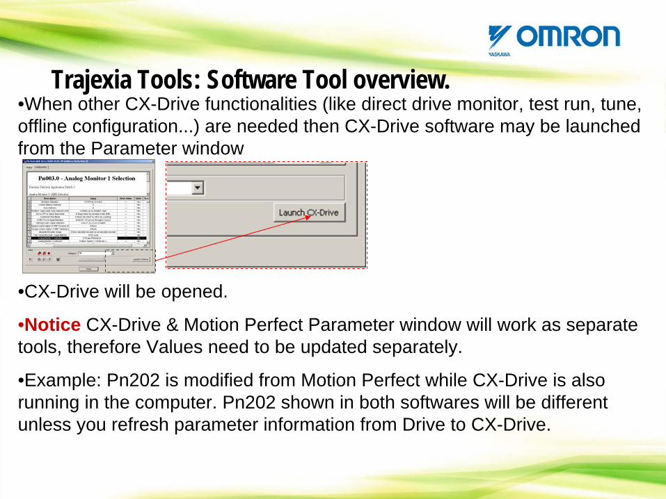
•When other CX-Drive functionalities (like direct drive monitor, test run, tune, offline configuration...) are needed then CX-Drive software may be launched from the Parameter window
•CX-Drive will be opened.
•Notice CX-Drive & Motion Perfect Parameter window will work as separate tools, therefore Values need to be updated separately.
•Example: Pn202 is modified from Motion Perfect while CX-Drive is also running in the computer. Pn202 shown in both softwares will be different unless you refresh parameter information from Drive to CX-Drive.
Trajexia Tools: Software Tool overview.
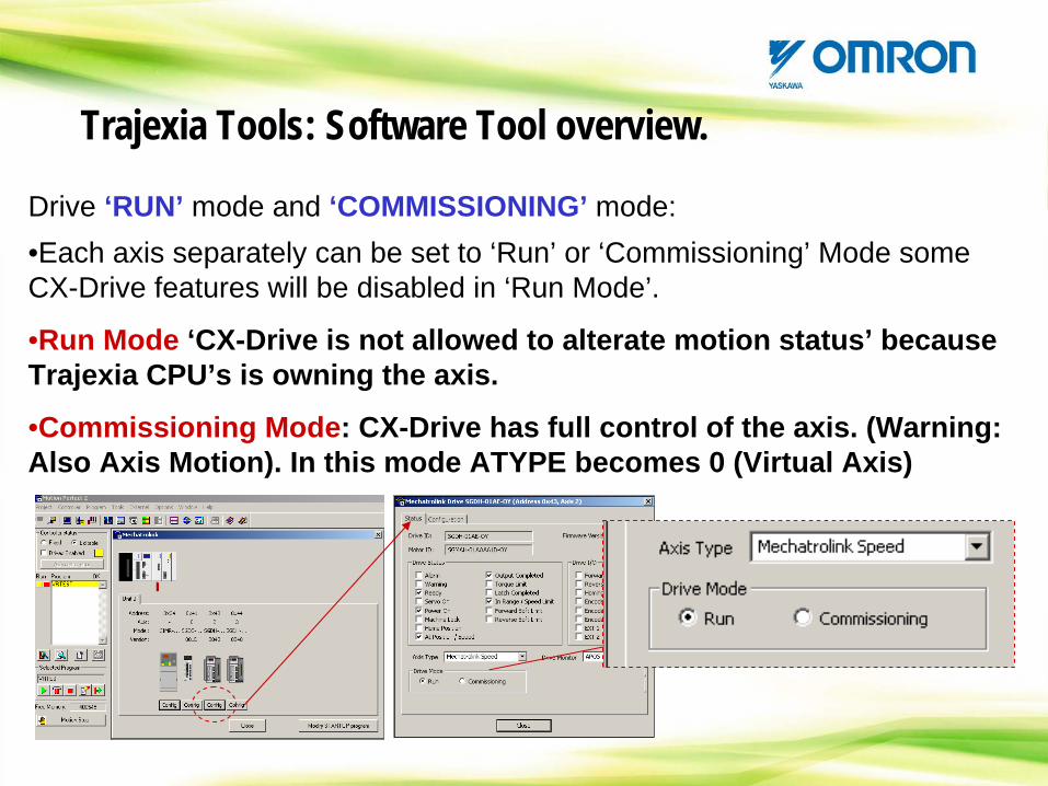
Drive ‘RUN’ mode and ‘COMMISSIONING’ mode:•Each axis separately can be set to ‘Run’ or ‘Commissioning’ Mode some CX-Drive features will be disabled in ‘Run Mode’.
•Run Mode ‘CX-Drive is not allowed to alterate motion status’ because Trajexia CPU’s is owning the axis.
•Commissioning Mode: CX-Drive has full control of the axis. (Warning: Also Axis Motion). In this mode ATYPE becomes 0 (Virtual Axis)
Trajexia Tools: Software Tool overview.
HANDS ON
CHECK YOUR TrajeXia configuration
Trajexia Tools: Software Tool overview.
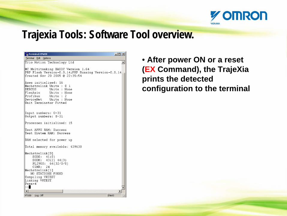
• After power ON or a reset (EX Command), the TrajeXia prints the detected configuration to the terminal
Trajexia Tools: Software Tool overview.
CONTENTS
TrajeXia OverviewHardware and general specification TrajeXia ToolsTrajexia ArchitectureProgramming TrajeXiaHow I do… with TrajeXia?CommunicationTrajeXia success historiesApplication discussion
CONTENTS: Trajexia Architecture
-TrajeXia processing architecture-Program execution. Tasks and multitasking-Axes in TrajeXia-Motion buffers & Task buffer
Program BufferProgram Buffer
BASIC PROGRAMSTask 1
Task 2
Task 3
…
Task 14
Comms
BASIC PROGRAMSTask 1
Task 2
Task 3
…
Task 14
Comms
TJ1-MC__
MC I/O
AXIS TYPEAXIS TYPE
ML_POSITION
TJ1-ML__TJ1-ML__ML command
Servo drive.
MOTOR
ENC
ML_SPEED
ML_TORQUE
AXIS CONTROL LOOPAXIS CONTROL LOOP
Position Loop
Position Loop
Motion command
Position Loop
Position Loop
Speed LoopSpeed Loop
Torque Loop
Torque Loop
Buffer & profile
gererator
Buffer & profile
gererator
Trajexia Architecture: Processing architecture
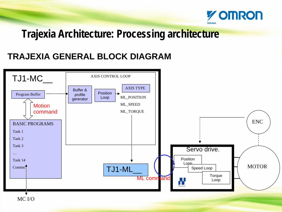
TRAJEXIA GENERAL BLOCK DIAGRAM
Trajexia Architecture: Processing architecture
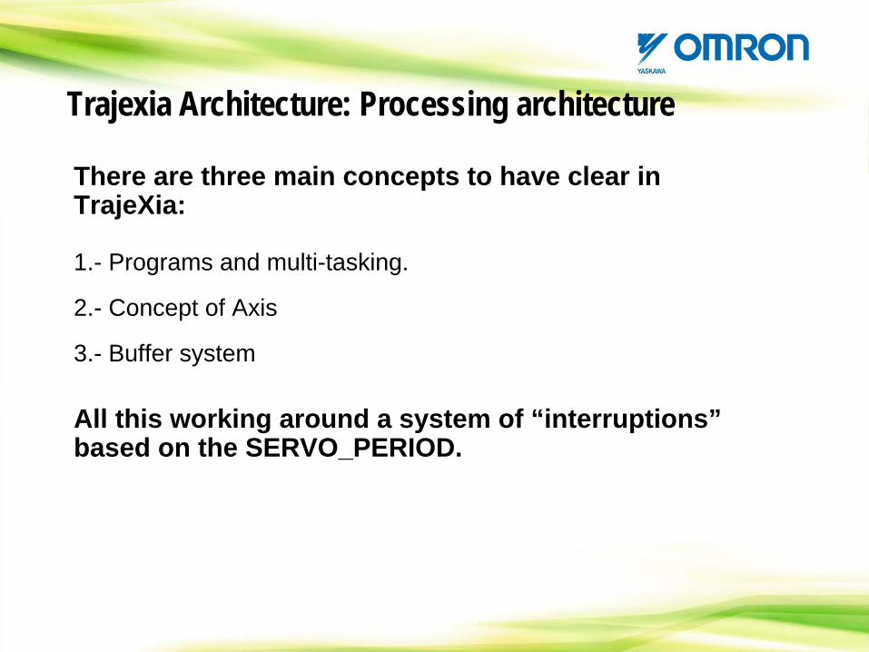
There are three main concepts to have clear in TrajeXia:
1.- Programs and multi-tasking.
2.- Concept of Axis
3.- Buffer system
All this working around a system of “interruptions” based on the SERVO_PERIOD.
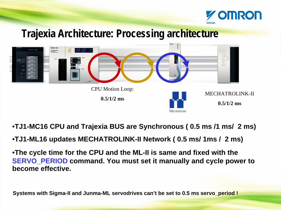
CPU Motion Loop:
0.5/1/2 ms
•TJ1-MC16 CPU and Trajexia BUS are Synchronous ( 0.5 ms /1 ms/ 2 ms)
•TJ1-ML16 updates MECHATROLINK-II Network ( 0.5 ms/ 1ms / 2 ms)
•The cycle time for the CPU and the ML-II is same and fixed with the SERVO_PERIOD command. You must set it manually and cycle power to become effective.
MECHATROLINK-II
0.5/1/2 ms
Systems with Sigma-II and Junma-ML servodrives can’t be set to 0.5 ms servo_period !
Trajexia Architecture: Processing architecture
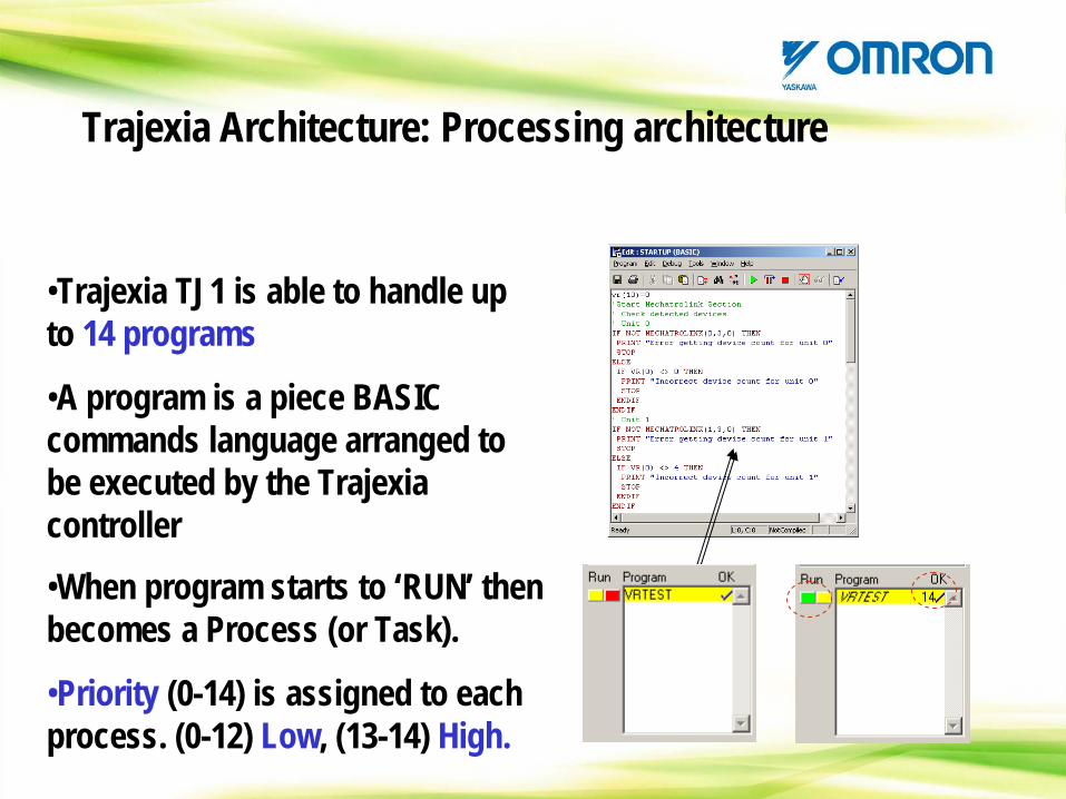
•Trajexia TJ1 is able to handle up to 14 programs
•A program is a piece BASIC commands language arranged to be executed by the Trajexia controller•When program starts to ‘RUN’ then becomes a Process (or Task).
•Priority (0-14) is assigned to each process. (0-12) Low, (13-14) High.
Trajexia Architecture: Processing architecture
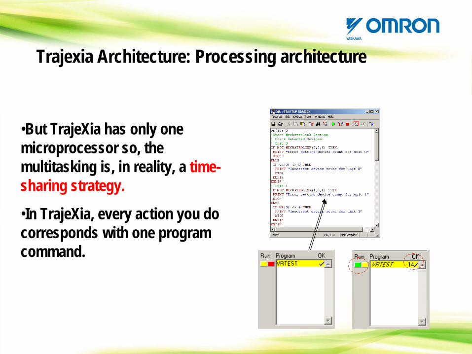
•But TrajeXia has only one microprocessor so, the multitasking is, in reality, a time- sharing strategy.
•In TrajeXia, every action you do corresponds with one program command.
Trajexia Architecture: Processing architecture
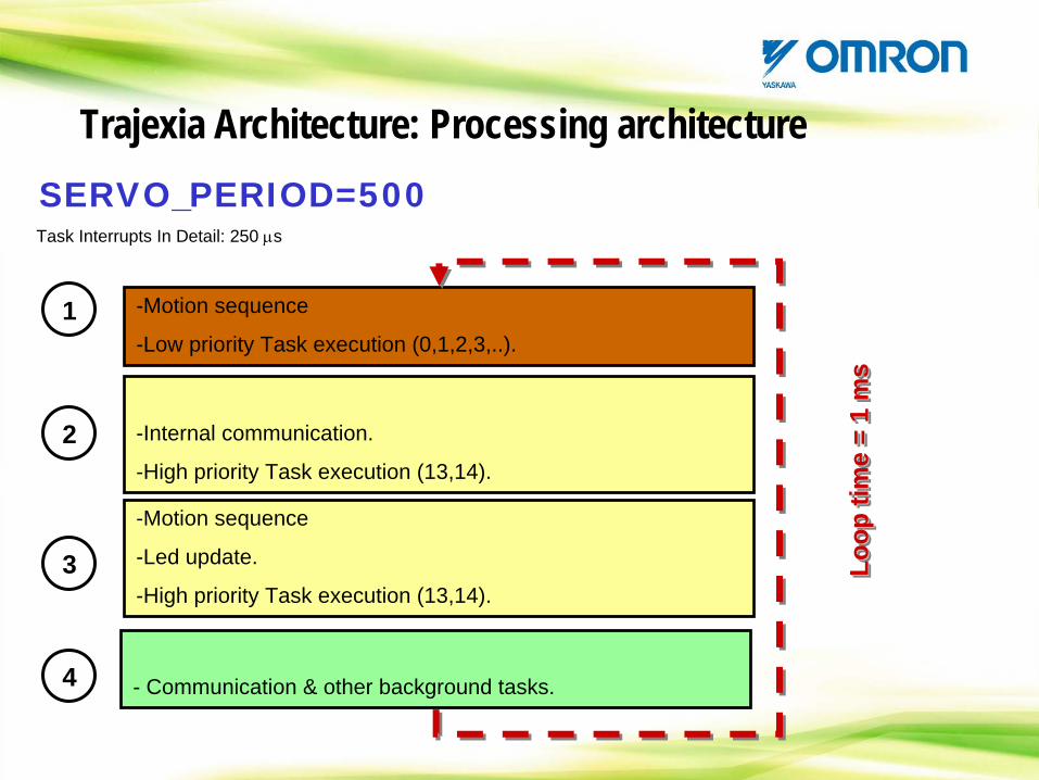
-Motion sequence
-Low priority Task execution (0,1,2,3,..).
-Internal communication.
-High priority Task execution (13,14).
-Motion sequence
-Led update.
-High priority Task execution (13,14).
- Communication & other background tasks.
1
2
3 Loop
tim
e =
1 m
sLo
op ti
me
= 1
ms
Loop
tim
e =
1 m
s
Task Interrupts In Detail: 250 μs
4
Trajexia Architecture: Processing architectureSERVO_PERIOD=500

-Motion sequence
-Low priority Task execution (0,1,2,3,..).
-Internal communication.
-High priority Task execution (13,14).
-Led update.
-High priority Task execution (13,14).
- Communication & other background tasks.
1
2
3
Loop
tim
e =
1 m
sLo
op ti
me
= 1
ms
Loop
tim
e =
1 m
s
Task Interrupts In Detail: 250 μs
4
Trajexia Architecture: Processing architectureSERVO_PERIOD=1000
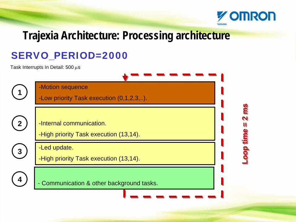
-Motion sequence
-Low priority Task execution (0,1,2,3,..).
-Internal communication.
-High priority Task execution (13,14).
-Led update.
-High priority Task execution (13,14).
- Communication & other background tasks.
1
2
3
Loop
tim
e =
2 m
sLo
op ti
me
= 2
ms
Loop
tim
e =
2 m
s
Task Interrupts In Detail: 500 μs
4
Trajexia Architecture: Processing architectureSERVO_PERIOD=2000
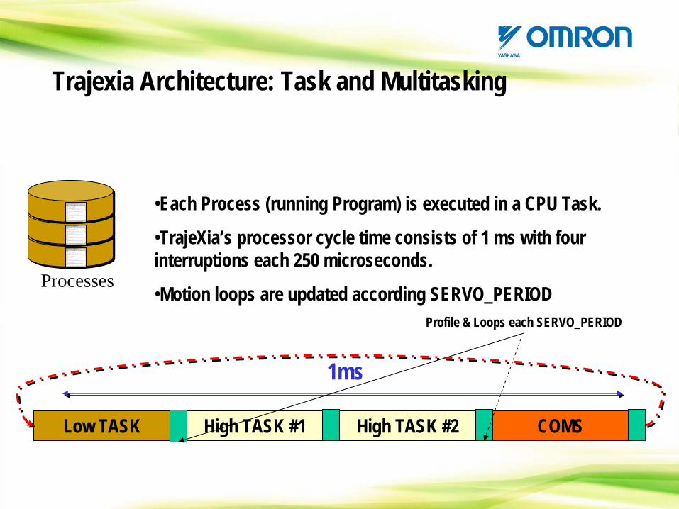
•Each Process (running Program) is executed in a CPU Task.
•TrajeXia’s processor cycle time consists of 1 ms with four interruptions each 250 microseconds.
•Motion loops are updated according SERVO_PERIOD
High TASK #1 High TASK #2Low TASK COMS
1ms
Profile & Loops each SERVO_PERIOD
Processes
Trajexia Architecture: Task and Multitasking
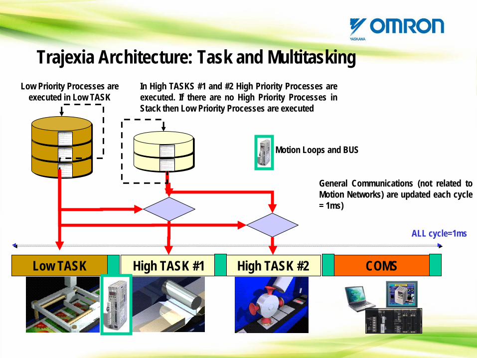
High TASK #1 High TASK #2Low TASK COMS
ALL cycle=1ms
Low Priority Processes are executed in Low TASK
Motion Loops and BUS
In High TASKS #1 and #2 High Priority Processes are executed. If there are no High Priority Processes in Stack then Low Priority Processes are executed
General Communications (not related to Motion Networks) are updated each cycle = 1ms)
Trajexia Architecture: Task and Multitasking
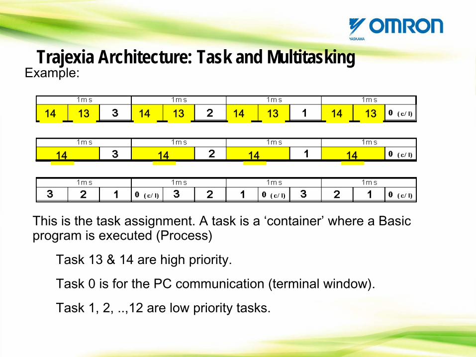
This is the task assignment. A task is a ‘container’
where a Basic program is executed (Process)
Task 13 & 14 are high priority.
Task 0 is for the PC communication (terminal window).
Task 1, 2, ..,12 are low priority tasks.
13 13 13 1314 14 14 14
14 14 14 14
Example:Trajexia Architecture: Task and Multitasking
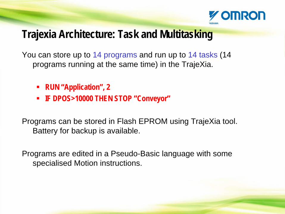
You can store up to 14 programs and run up to 14 tasks (14 programs running at the same time) in the TrajeXia.
RUN “Application”, 2IF DPOS>10000 THEN STOP ”Conveyor”
Programs can be stored in Flash EPROM using TrajeXia tool. Battery for backup is available.
Programs are edited in a Pseudo-Basic language with some specialised Motion instructions.
Trajexia Architecture: Task and Multitasking
HANDS ON
Let’s test the Tasks priority
Trajexia Architecture: Task and Multitasking
Program BufferProgram Buffer
BASIC PROGRAMSTask 1
Task 2
Task 3
…
Task 14
Comms
BASIC PROGRAMSTask 1
Task 2
Task 3
…
Task 14
Comms
TJ1-ML16
MC I/O
AXIS TYPEAXIS TYPE
ML_POSITION
TJ1-ML16TJ1-ML16ML command
Servo drive.
MOTOR
ENC
ML_SPEED
ML_TORQUE
AXIS CONTROL LOOPAXIS CONTROL LOOP
Position Loop
Position Loop
Motion command
Position Loop
Position Loop
Speed LoopSpeed Loop
Torque Loop
Torque Loop
Buffer & profile
gererator
Buffer & profile
gererator
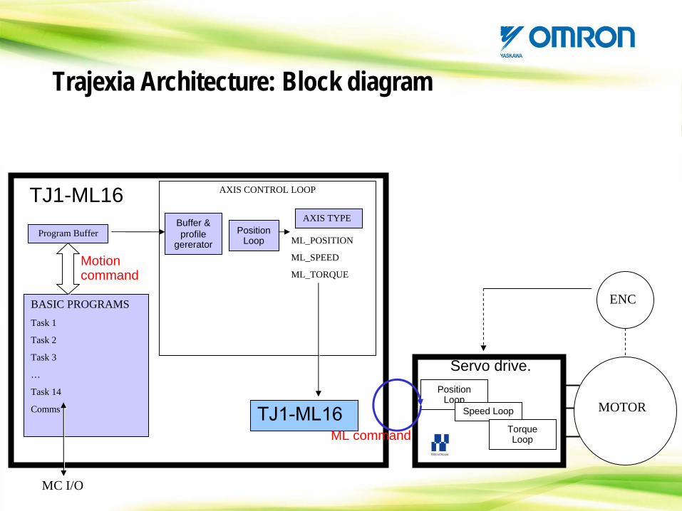
Trajexia Architecture: Block diagram
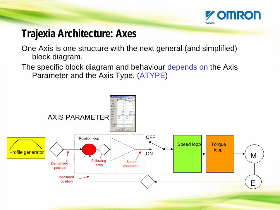
One Axis is one structure with the next general (and simplified) block diagram.
The specific block diagram and behaviour depends on the Axis Parameter and the Axis Type. (ATYPE)
Profile generator
+
-
Position loop
Demandedposition
Measuredposition
Followingerror
Speedcommand
Speed loop
ON
OFFTorque
loopM
E
AXIS PARAMETER
Trajexia Architecture: Axes
Profile generator
DEMANDPOSITION
BASIC PROGRAM
.......
.......MOVE(1000)..............
CYCLE DPOS 0 01 252 1003 225… …97 987598 997599 10000
100 10000
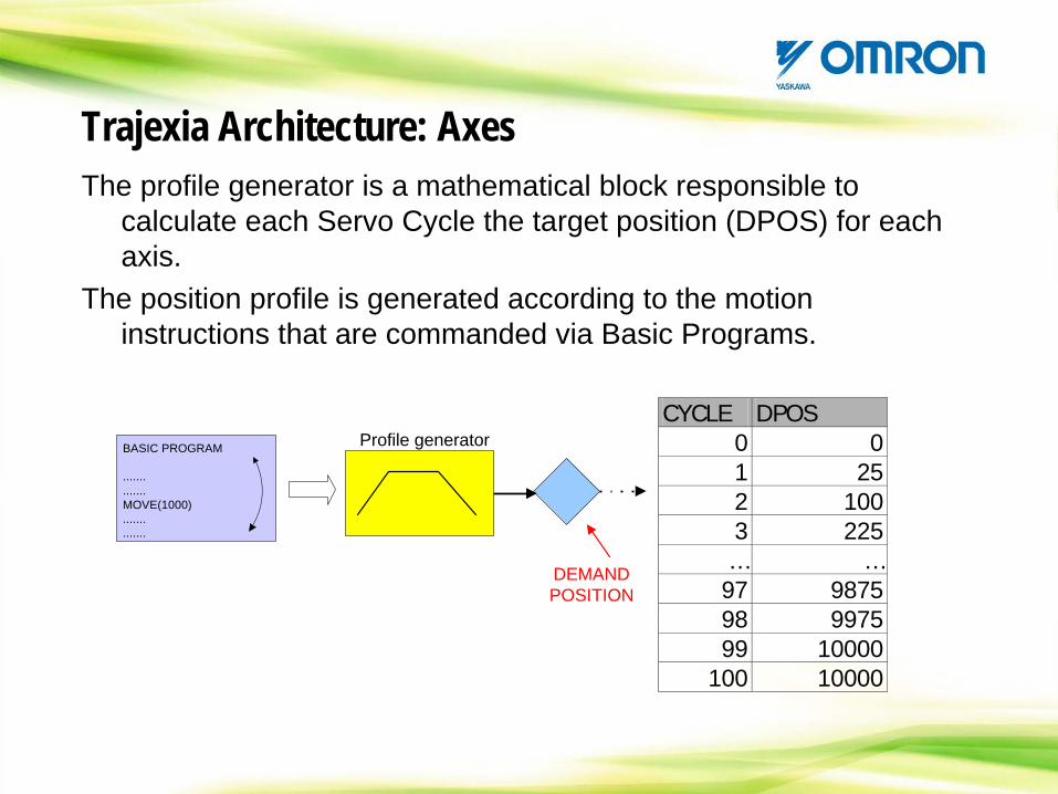
The profile generator is a mathematical block responsible to calculate each Servo Cycle the target position (DPOS) for each axis.
The position profile is generated according to the motion instructions that are commanded via Basic Programs.
Trajexia Architecture: Axes
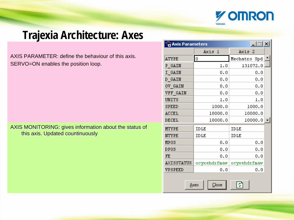
AXIS PARAMETER: define the behaviour of this axis.SERVO=ON enables the position loop.
AXIS MONITORING: gives information about the status of this axis. Updated countinuously
AXIS MONITORING: gives information about the status of this axis. Updated countinuously
Trajexia Architecture: Axes
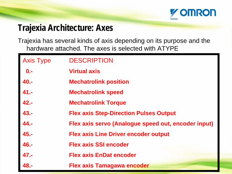
Trajexia has several kinds of axis depending on its purpose and the hardware attached. The axes is selected with ATYPE
Axis Type DESCRIPTION0.- Virtual axis
40.- Mechatrolink position
41.- Mechatrolink speed
42.- Mechatrolink Torque
43.- Flex axis Step-Direction Pulses Output
44.- Flex axis servo (Analogue speed out, encoder input)
45.- Flex axis Line Driver encoder output
46.- Flex axis SSI encoder
47.- Flex axis EnDat encoder
48.- Flex axis Tamagawa encoder
Trajexia Architecture: Axes
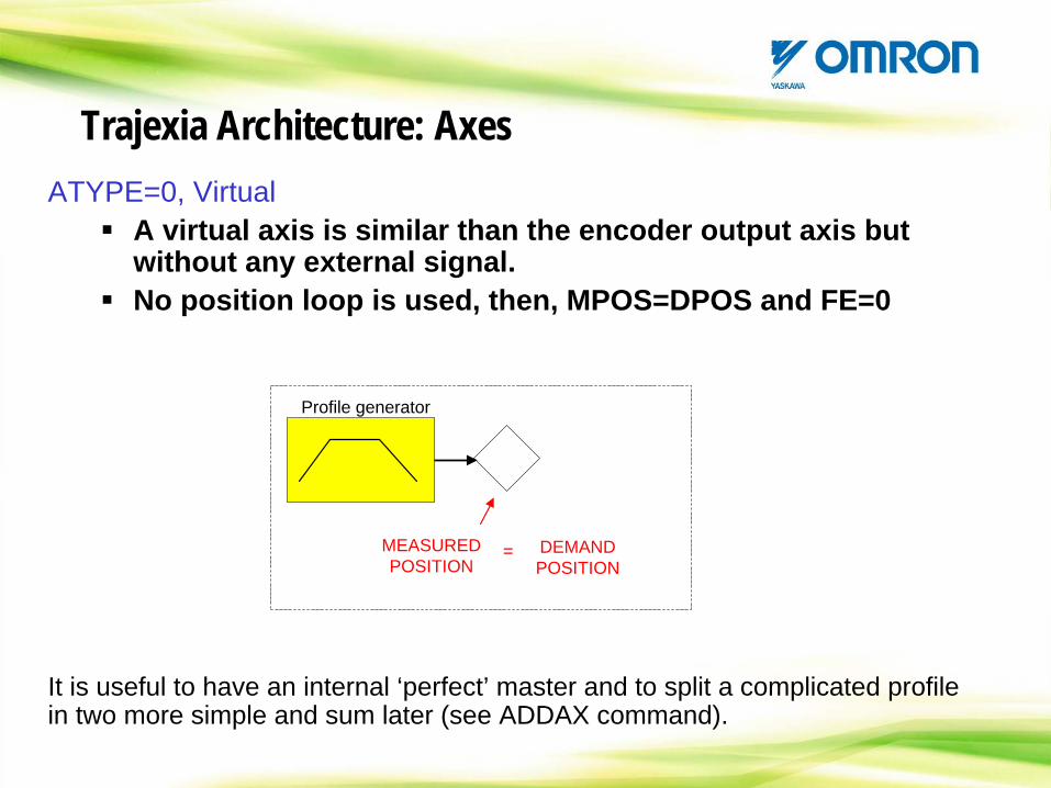
ATYPE=0, VirtualA virtual axis is similar than the encoder output axis but without any external signal. No position loop is used, then, MPOS=DPOS and FE=0
Profile generator
MEASUREDPOSITION
DEMANDPOSITION
=
Trajexia Architecture: Axes
It is useful to have an internal ‘perfect’ master and to split a complicated profile in two more simple and sum later (see ADDAX command).
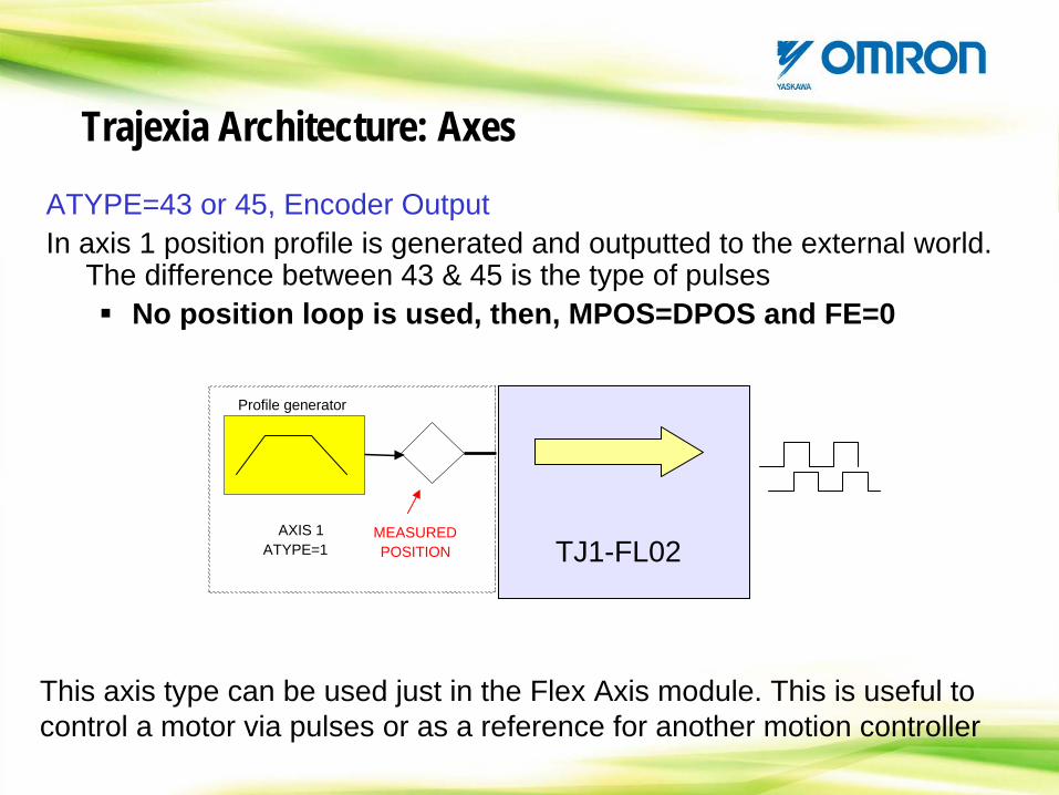
ATYPE=43 or 45, Encoder Output In axis 1 position profile is generated and outputted to the external world.
The difference between 43 & 45 is the type of pulsesNo position loop is used, then, MPOS=DPOS and FE=0
Profile generator
AXIS 1ATYPE=1
MEASUREDPOSITION TJ1-FL02
This axis type can be used just in the Flex Axis module. This is useful to control a motor via pulses or as a reference for another motion controller
Trajexia Architecture: Axes
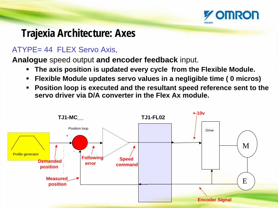
ATYPE= 44 FLEX Servo Axis,Analogue speed output and encoder feedback input.
The axis position is updated every cycle from the Flexible Module.Flexible Module updates servo values in a negligible time ( 0 micros)Position loop is executed and the resultant speed reference sent to the servo driver via D/A converter in the Flex Ax module.
+
-Profile generator
Position loop
Demandedposition
Measuredposition
Followingerror
Speedcommand
Drive
M
E
+-10v
Encoder Signal
TJ1-FL02TJ1-MC__
Trajexia Architecture: Axes
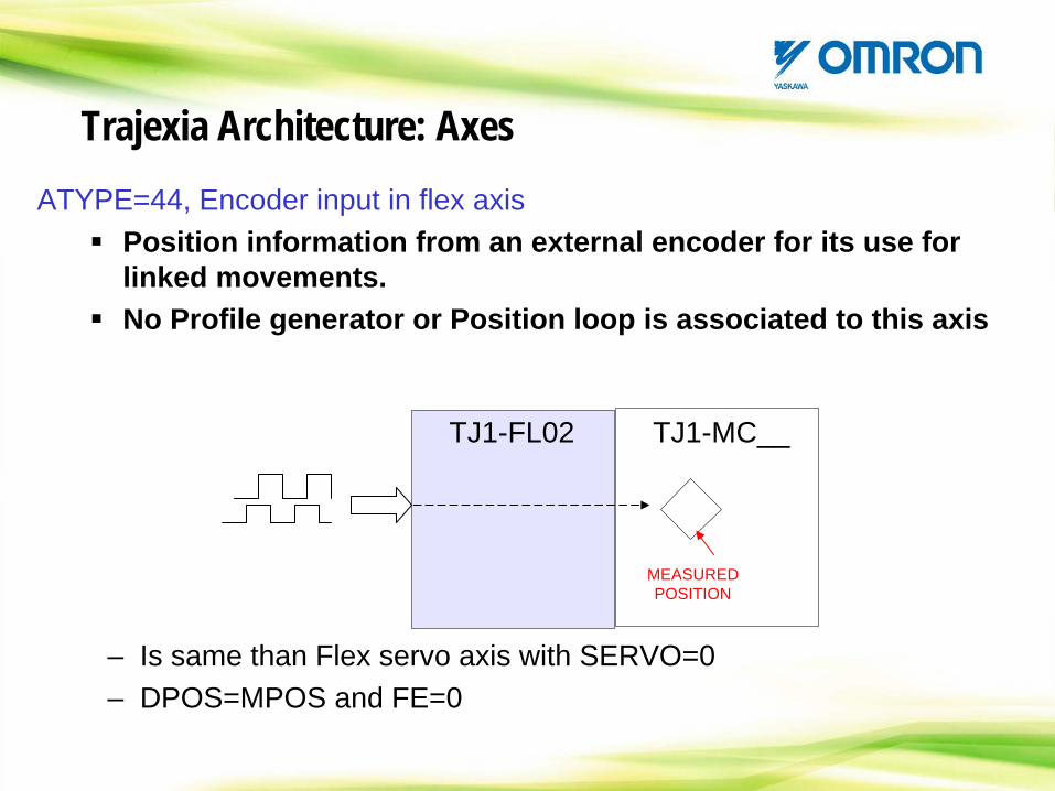
ATYPE=44, Encoder input in flex axisPosition information from an external encoder for its use for linked movements.No Profile generator or Position loop is associated to this axis
– Is same than Flex servo axis with SERVO=0– DPOS=MPOS and FE=0
MEASUREDPOSITION
TJ1-FL02 TJ1-MC__
Trajexia Architecture: Axes
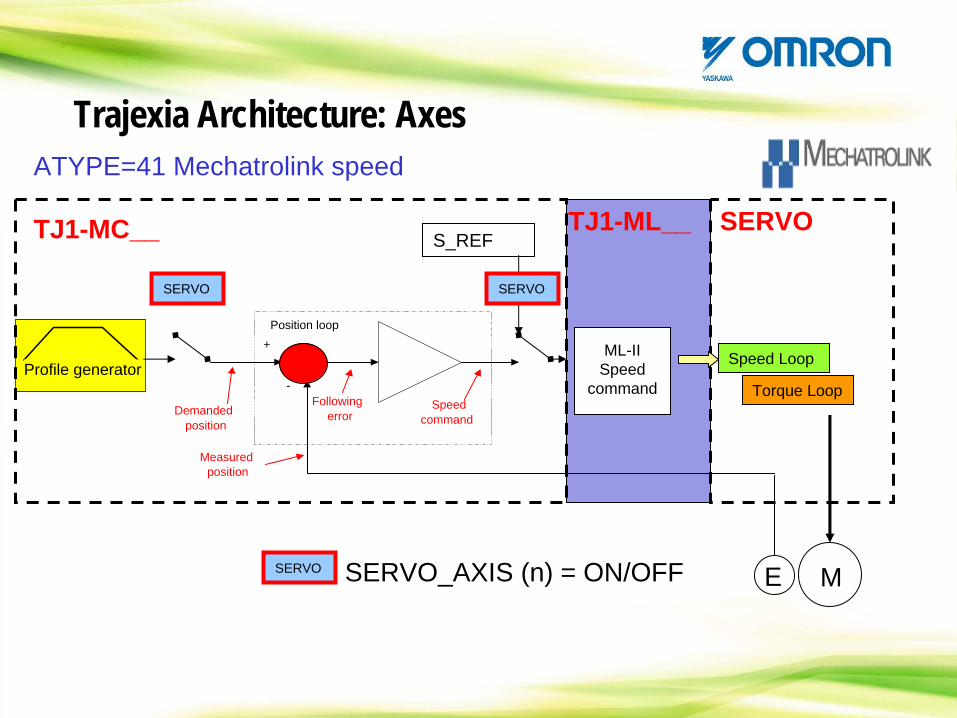
ATYPE=41 Mechatrolink speed
Profile generator+
-
Position loop
Demandedposition
Measuredposition
Followingerror
Speedcommand
S_REF
ML-II Speed
command
Speed Loop
Torque Loop
ME
TJ1-MC__ TJ1-ML__ SERVO
SERVO_AXIS (n) = ON/OFF
SERVOSERVO
SERVO
Trajexia Architecture: Axes
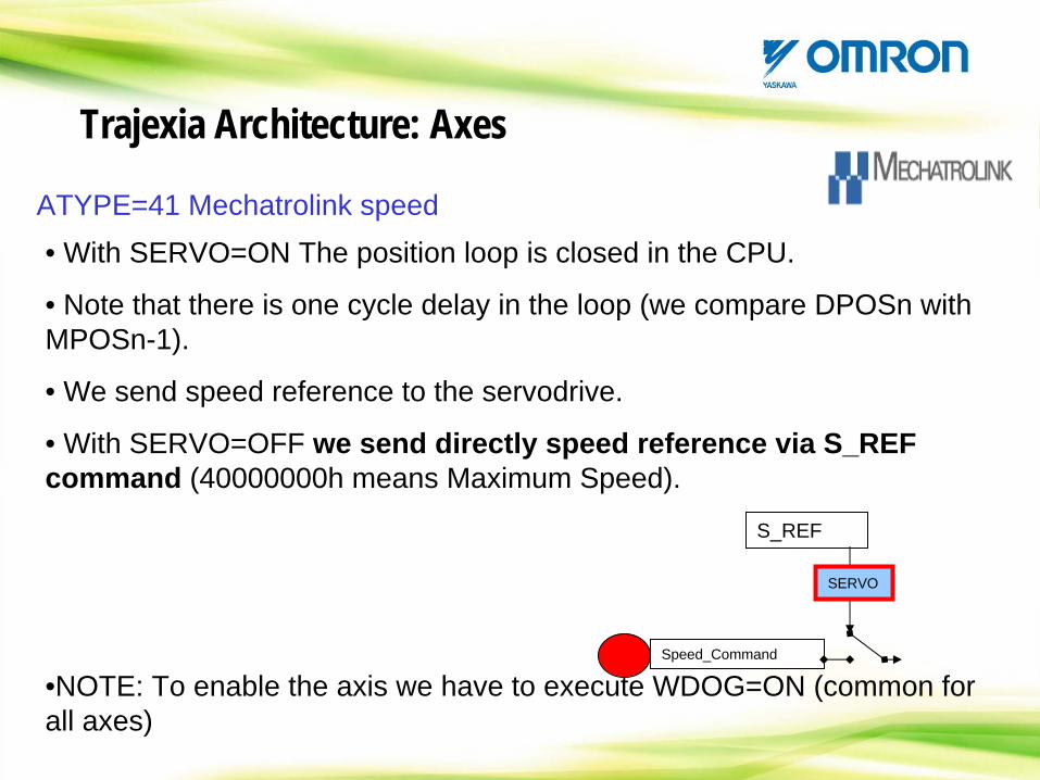
ATYPE=41 Mechatrolink speed• With SERVO=ON The position loop is closed in the CPU.
• Note that there is one cycle delay in the loop (we compare DPOSn with MPOSn-1).
• We send speed reference to the servodrive.
• With SERVO=OFF we send directly speed reference via S_REF command (40000000h means Maximum Speed).
•NOTE: To enable the axis we have to execute WDOG=ON (common for all axes)
S_REF
SERVO
Speed_Command
Trajexia Architecture: Axes
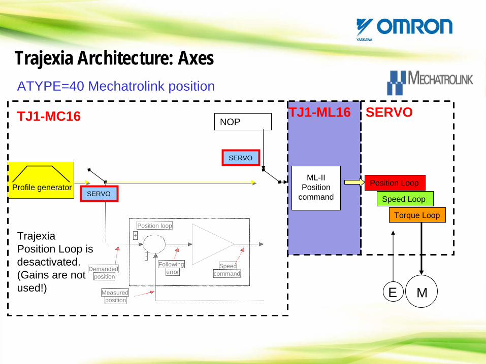
ATYPE=40 Mechatrolink position
Profile generator
+
-
Position loop
Demandedposition
Measuredposition
Followingerror
Speedcommand
NOP
ML-II Position
command Speed Loop
Torque Loop
ME
TJ1-MC16 TJ1-ML16 SERVO
Position LoopSERVO
SERVO
Trajexia Position Loop is desactivated. (Gains are not used!)
Trajexia Architecture: Axes
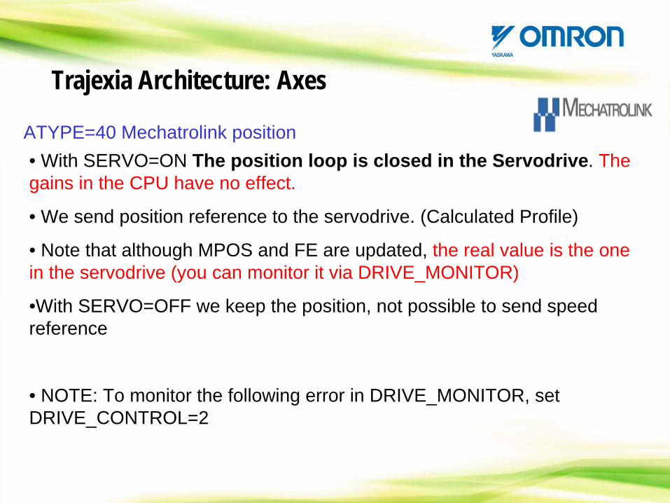
ATYPE=40 Mechatrolink position• With SERVO=ON The position loop is closed in the Servodrive. The gains in the CPU have no effect.
• We send position reference to the servodrive. (Calculated Profile)
• Note that although MPOS and FE are updated, the real value is the one in the servodrive (you can monitor it via DRIVE_MONITOR)
•With SERVO=OFF we keep the position, not possible to send speed reference
• NOTE: To monitor the following error in DRIVE_MONITOR, set DRIVE_CONTROL=2
Trajexia Architecture: Axes
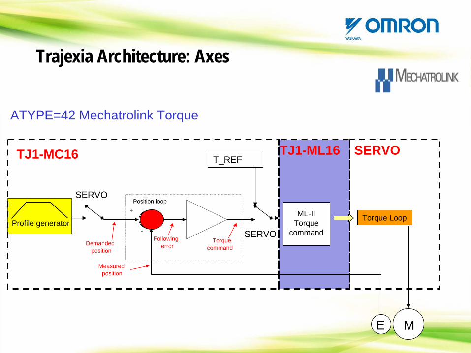
ATYPE=42 Mechatrolink Torque
Profile generator+
-
Position loop
Demandedposition
Measuredposition
Followingerror
Torquecommand
T_REF
ML-II Torque
command
Torque Loop
ME
TJ1-MC16 TJ1-ML16 SERVO
SERVO
SERVO
Trajexia Architecture: Axes
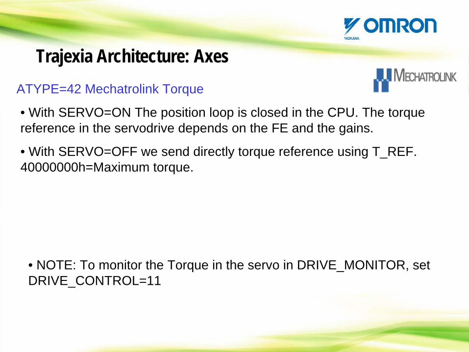
ATYPE=42 Mechatrolink Torque
• With SERVO=ON The position loop is closed in the CPU. The torque reference in the servodrive depends on the FE and the gains.
• With SERVO=OFF we send directly torque reference using T_REF. 40000000h=Maximum torque.
• NOTE: To monitor the Torque in the servo in DRIVE_MONITOR, set DRIVE_CONTROL=11
Trajexia Architecture: Axes
Summary of Mechatrolink modes
Trajexia Architecture: Axes
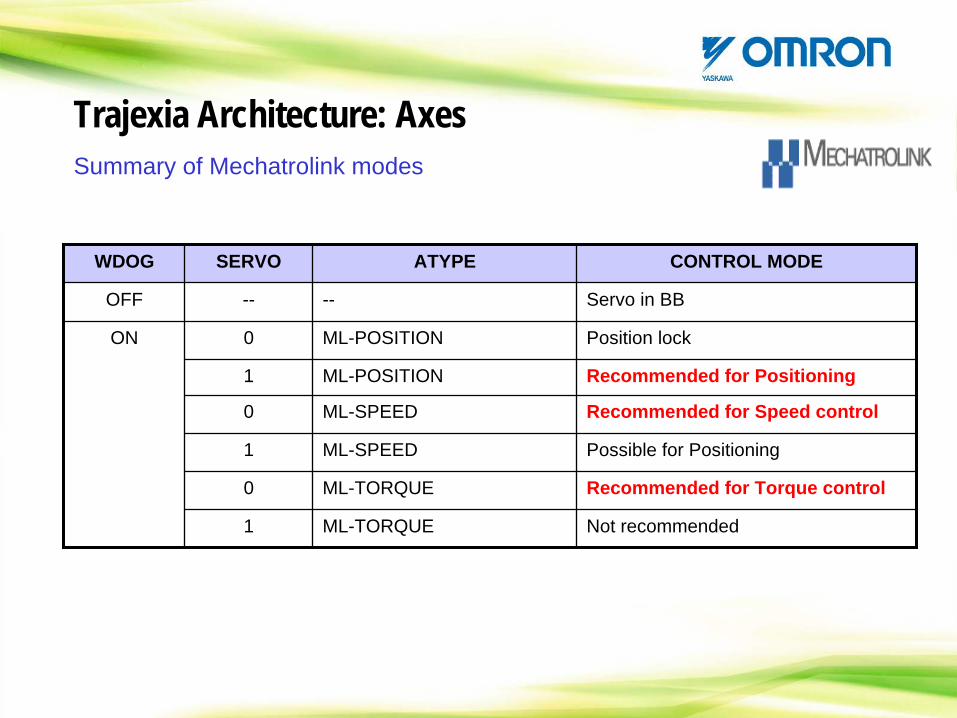
WDOG SERVO ATYPE CONTROL MODE
OFF -- -- Servo in BB
ON 0 ML-POSITION Position lock
1 ML-POSITION Recommended for Positioning
0 ML-SPEED Recommended for Speed control
1 ML-SPEED Possible for Positioning
0 ML-TORQUE Recommended for Torque control
1 ML-TORQUE Not recommended
HANDS ON
Let’s check the different ATYPE’s
Trajexia Architecture: Axes
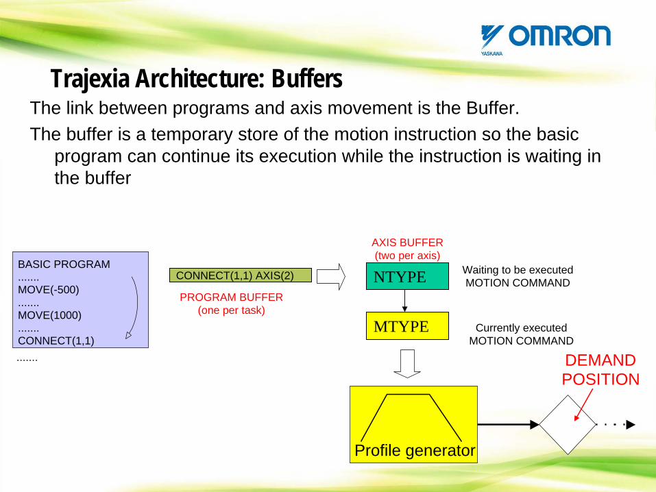
The link between programs and axis movement is the Buffer.The buffer is a temporary store of the motion instruction so the basic
program can continue its execution while the instruction is waiting in the buffer
DEMANDPOSITION
.......
BASIC PROGRAM.......MOVE(-500).......MOVE(1000).......CONNECT(1,1)
CONNECT(1,1) AXIS(2)
PROGRAM BUFFER (one per task)
NTYPE
MTYPE
Waiting to be executed MOTION COMMAND
Currently executed MOTION COMMAND
AXIS BUFFER (two per axis)
Profile generator
Trajexia Architecture: Buffers
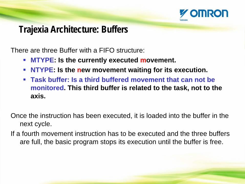
There are three Buffer with a FIFO structure:MTYPE: Is the currently executed movement.NTYPE: Is the new movement waiting for its execution.Task buffer: Is a third buffered movement that can not be monitored. This third buffer is related to the task, not to the axis.
Once the instruction has been executed, it is loaded into the buffer in the next cycle.
If a fourth movement instruction has to be executed and the three buffers are full, the basic program stops its execution until the buffer is free.
Trajexia Architecture: Buffers
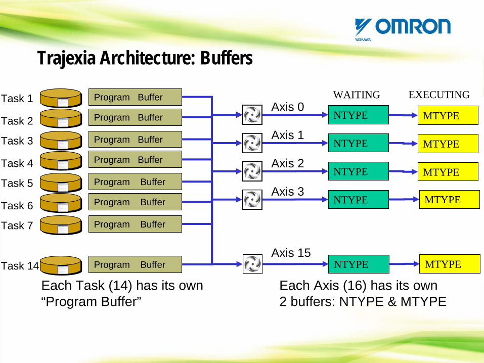
Task 1 Program Buffer Axis 0
NTYPE MTYPE
WAITING EXECUTING
Each Task (14) has its own “Program Buffer”
Program Buffer Task 2
Task 3 Program Buffer
Program Buffer Task 4
Task 5 Program Buffer
Program Buffer Task 6
Task 7 Program Buffer
Task 14 Program Buffer
Axis 1NTYPE MTYPE
Axis 2NTYPE MTYPE
Axis 3NTYPE MTYPE
NTYPE MTYPEAxis 15
Each Axis (16) has its own 2 buffers: NTYPE & MTYPE
Trajexia Architecture: Buffers
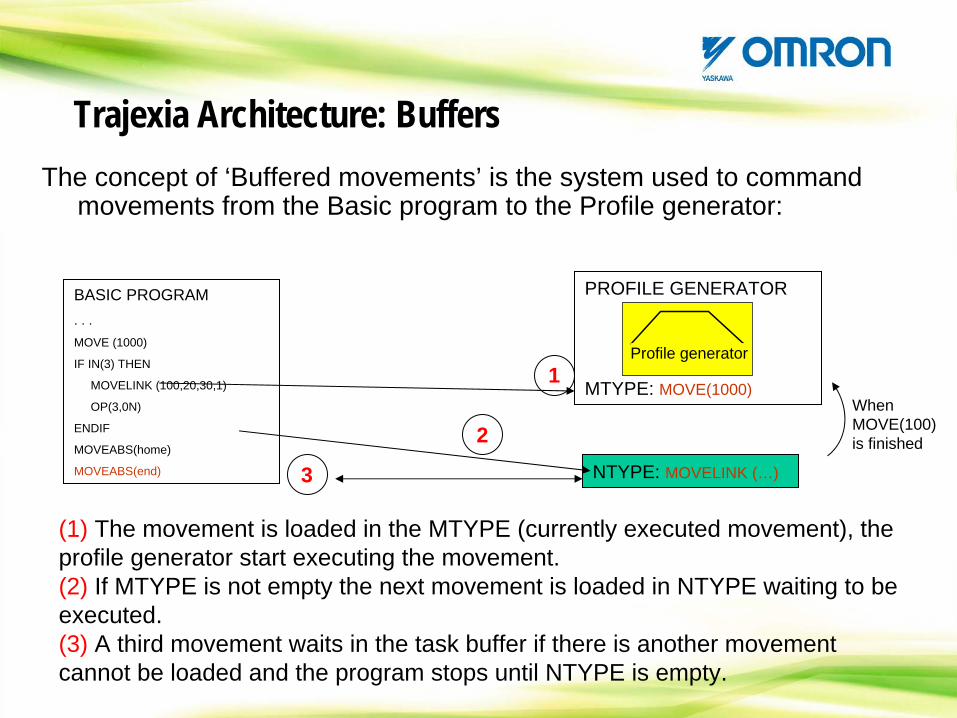
The concept of ‘Buffered movements’ is the system used to command movements from the Basic program to the Profile generator:
When MOVE(100) is finished
BASIC PROGRAM. . .MOVE (1000)
IF IN(3) THEN
MOVELINK (100,20,30,1)
OP(3,0N)
ENDIF
MOVEABS(home)
MOVEABS(end)
PROFILE GENERATOR
MTYPE: MOVE(1000)
NTYPE: MOVELINK (…)3
2
1Profile generator
(1) The movement is loaded in the MTYPE (currently executed movement), the profile generator start executing the movement.(2) If MTYPE is not empty the next movement is loaded in NTYPE waiting to be executed.(3) A third movement waits in the task buffer if there is another movement cannot be loaded and the program stops until NTYPE is empty.
Trajexia Architecture: Buffers
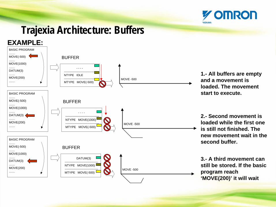
BASIC PROGRAM.......MOVE(-500).......MOVE(1000).......DATUM(3).......MOVE(200).......
- - - ----------------------------------NTYPE IDLE---------------------------------MTYPE MOVE(-500)
BUFFER
MOVE -500
BASIC PROGRAM.......MOVE(-500).......MOVE(1000).......DATUM(3).......MOVE(200).......
- - - ----------------------------------NTYPE MOVE(1000)---------------------------------MTYPE MOVE(-500)
BUFFER
MOVE -500
BASIC PROGRAM.......MOVE(-500).......MOVE(1000).......DATUM(3).......MOVE(200).......
DATUM(3)---------------------------------NTYPE MOVE(1000)---------------------------------MTYPE MOVE(-500)
BUFFER
MOVE -500
2.- Second movement is loaded while the first one is still not finished. The new movement wait in the second buffer.
3.- A third movement can still be stored. If the basic program reach ‘MOVE(200)’ it will wait
1.- All buffers are empty and a movement is loaded. The movement start to execute.
EXAMPLE:EXAMPLE:EXAMPLE:Trajexia Architecture: Buffers
5.- As the sended movements are finished, the buffer is becoming empty.
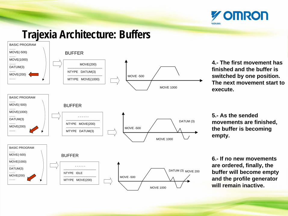
BASIC PROGRAM.......MOVE(-500).......MOVE(1000).......DATUM(3).......MOVE(200).......
- - - - - ----------------------------------NTYPE MOVE(200)---------------------------------MTYPE DATUM(3)
BUFFER
MOVE -500
MOVE 1000
DATUM (3)
BASIC PROGRAM.......MOVE(-500).......MOVE(1000).......DATUM(3).......MOVE(200).......
- - - - - ----------------------------------NTYPE IDLE---------------------------------MTYPE MOVE(200)
BUFFER
MOVE -500
MOVE 1000
DATUM (3) MOVE 200
6.- If no new movements are ordered, finally, the buffer will become empty and the profile generator will remain inactive.
4.- The first movement has finished and the buffer is switched by one position. The next movement start to execute.
BASIC PROGRAM.......MOVE(-500).......MOVE(1000).......DATUM(3).......MOVE(200).......
MOVE(200)---------------------------------NTYPE DATUM(3)---------------------------------MTYPE MOVE(1000)
BUFFER
MOVE -500
MOVE 1000
Trajexia Architecture: Buffers
HANDS ON
Let’s check the buffer behaviour
Trajexia Architecture: Buffers
CONTENTS
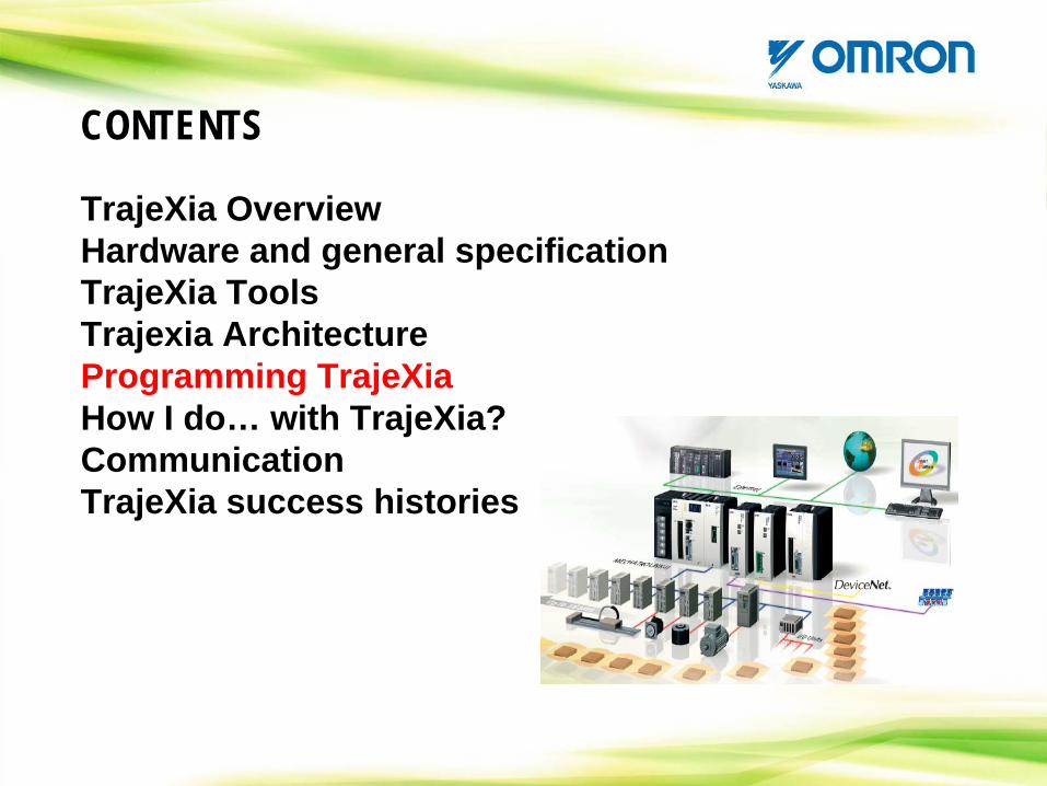
TrajeXia OverviewHardware and general specification TrajeXia ToolsTrajexia ArchitectureProgramming TrajeXiaHow I do… with TrajeXia?CommunicationTrajeXia success histories
CONTENTS: Programming TrajeXia
-Program/project handling-Loops and sequence commands-Motion commands-Variables-Good programming practices
Programming TrajeXia: Project Handling
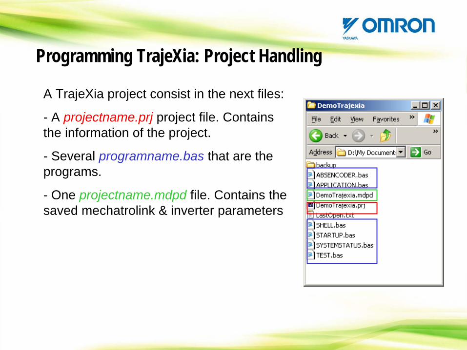
A TrajeXia project consist in the next files:
- A projectname.prj project file. Contains the information of the project.
- Several programname.bas that are the programs.
- One projectname.mdpd file. Contains the saved mechatrolink & inverter parameters
Programming TrajeXia: Project Handling
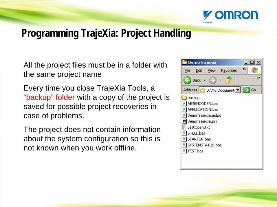
All the project files must be in a folder with the same project name
Every time you close TrajeXia Tools, a “backup” folder with a copy of the project is saved for possible project recoveries in case of problems.
The project does not contain information about the system configuration so this is not known when you work offline.
Programming TrajeXia: Project Handling
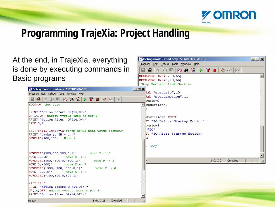
At the end, in TrajeXia, everything is done by executing commands in Basic programs
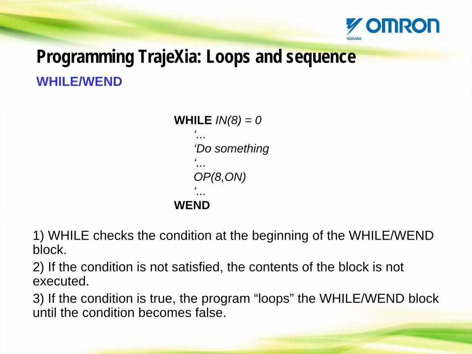
WHILE/WEND
WHILE IN(8) = 0‘...‘Do something‘...OP(8,ON)‘...
WEND
Programming TrajeXia: Loops and sequence
1) WHILE checks the condition at the beginning of the WHILE/WEND block.2) If the condition is not satisfied, the contents of the block is not executed.3) If the condition is true, the program “loops” the WHILE/WEND block until the condition becomes false.
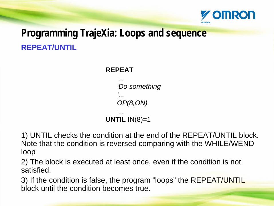
REPEAT/UNTIL
REPEAT‘...‘Do something‘...OP(8,ON)‘...
UNTIL IN(8)=1
Programming TrajeXia: Loops and sequence
1) UNTIL checks the condition at the end of the REPEAT/UNTIL block. Note that the condition is reversed comparing with the WHILE/WEND loop2) The block is executed at least once, even if the condition is not satisfied.3) If the condition is false, the program “loops” the REPEAT/UNTIL block until the condition becomes true.
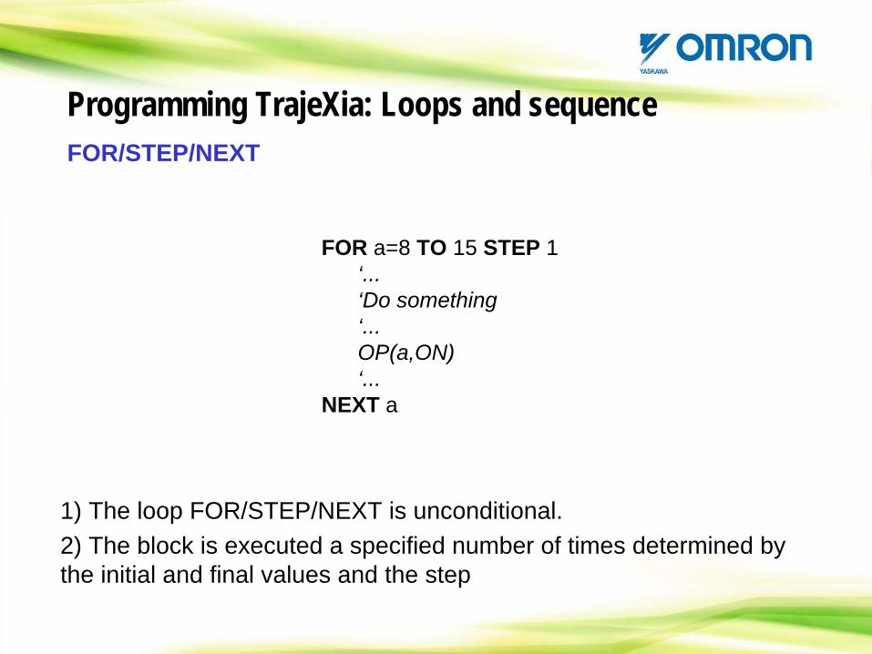
FOR a=8 TO 15 STEP 1‘...‘Do something‘...OP(a,ON)‘...
NEXT a
FOR/STEP/NEXT
1) The loop FOR/STEP/NEXT is unconditional.2) The block is executed a specified number of times determined by the initial and final values and the step
Programming TrajeXia: Loops and sequence
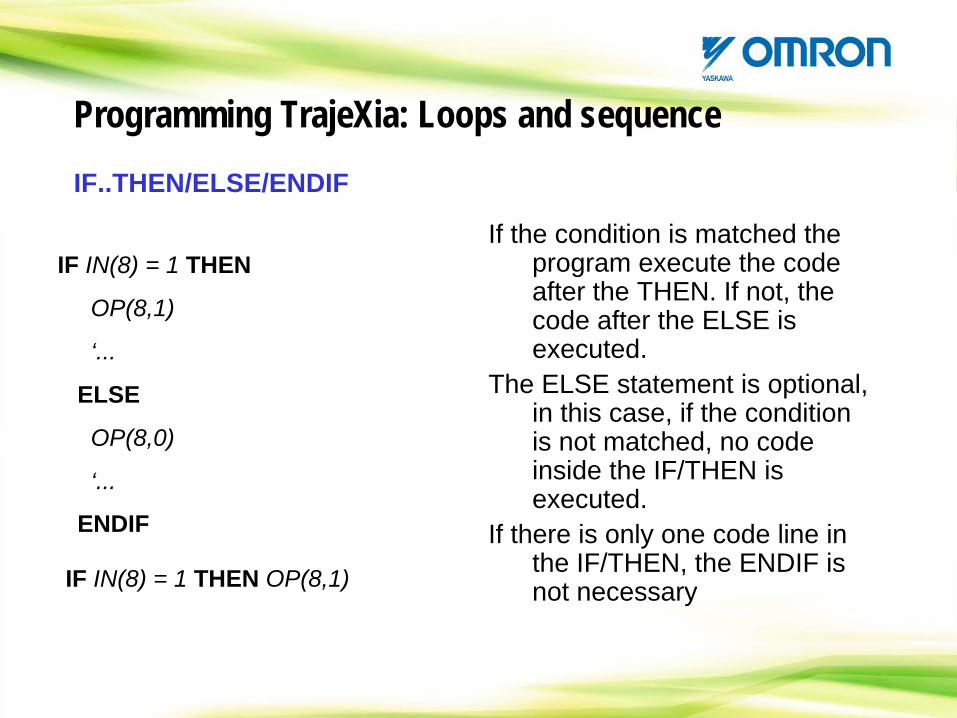
IF..THEN/ELSE/ENDIF
If the condition is matched the program execute the code after the THEN. If not, the code after the ELSE is executed.
The ELSE statement is optional, in this case, if the condition is not matched, no code inside the IF/THEN is executed.
If there is only one code line in the IF/THEN, the ENDIF is not necessaryIF IN(8) = 1 THEN OP(8,1)
IF IN(8) = 1 THEN
OP(8,1)
‘...
ELSE
OP(8,0)
‘...
ENDIF
Programming TrajeXia: Loops and sequence
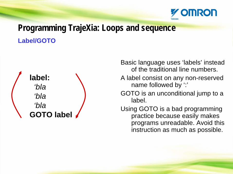
Label/GOTO
Basic language uses ‘labels’ instead of the traditional line numbers.
A label consist on any non-reserved name followed by ‘:’
GOTO is an unconditional jump to a label.
Using GOTO is a bad programming practice because easily makes programs unreadable. Avoid this instruction as much as possible.
label:‘bla‘bla‘bla
GOTO label
Programming TrajeXia: Loops and sequence
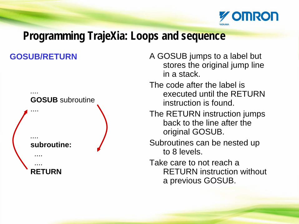
GOSUB/RETURN A GOSUB jumps to a label but stores the original jump line in a stack.
The code after the label is executed until the RETURN instruction is found.
The RETURN instruction jumps back to the line after the original GOSUB.
Subroutines can be nested up to 8 levels.
Take care to not reach a RETURN instruction without a previous GOSUB.
....GOSUB subroutine....
....subroutine:........
RETURN
Programming TrajeXia: Loops and sequence
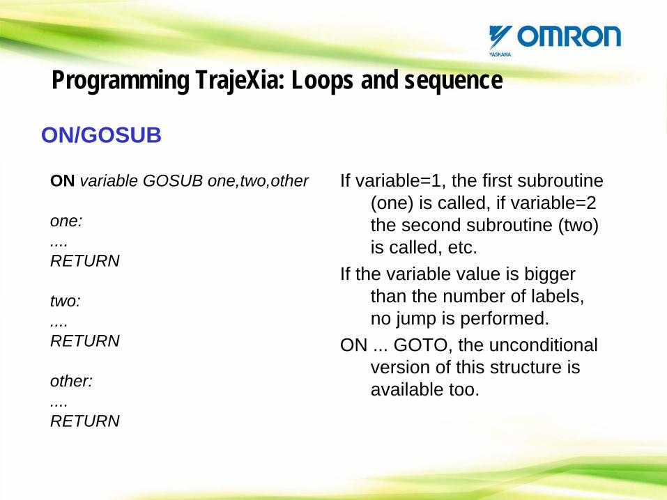
ON/GOSUB
If variable=1, the first subroutine (one) is called, if variable=2 the second subroutine (two) is called, etc.
If the variable value is bigger than the number of labels, no jump is performed.
ON ... GOTO, the unconditional version of this structure is available too.
ON variable GOSUB one,two,other
one:....RETURN
two:....RETURN
other:....RETURN
Programming TrajeXia: Loops and sequence
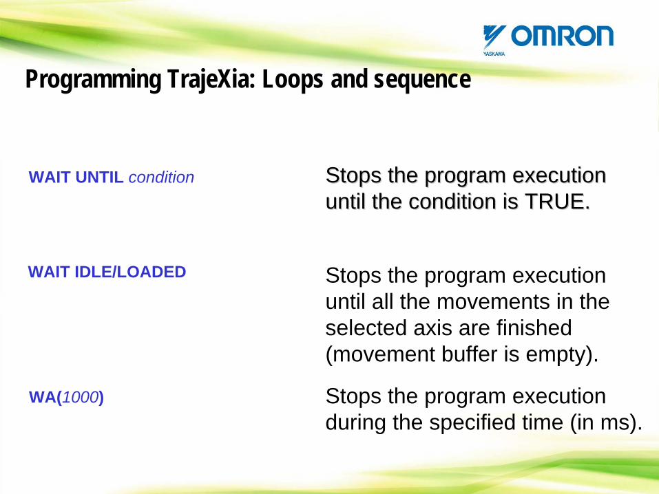
WAIT UNTIL condition
WA(1000)
WAIT IDLE/LOADED
Stops the program execution until the condition is TRUE. Stops the program execution Stops the program execution until the condition isuntil the condition is TRUE.TRUE.
Stops the program execution until all the movements in the selected axis are finished (movement buffer is empty).
Stops the program execution until all the movements in the selected axis are finished (movement buffer is empty).
Stops the program execution during the specified time (in ms). Stops the program execution during the specified time (in ms).
Programming TrajeXia: Loops and sequence
To control the position and performance of the different axis we have two different kind of commands:
Axis parameters:Used to select, adjust and monitor the different axis
Motion commands:Used, together with the profile generator, to create a motion profile in one or more axes.We can divide the motion instruction in two types:
Interpollated movements.Linked movements.
Programming TrajeXia: Motion commands
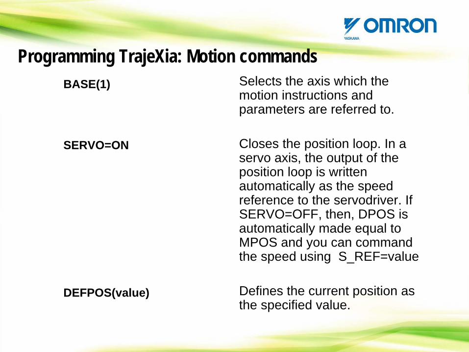
BASE(1)
SERVO=ON
DEFPOS(value)
Selects the axis which the motion instructions and parameters are referred to.
Closes the position loop. In a servo axis, the output of the position loop is written automatically as the speed reference to the servodriver. If SERVO=OFF, then, DPOS is automatically made equal to MPOS and you can command the speed using S_REF=value
Defines the current position as the specified value.
Programming TrajeXia: Motion commands
Set the Axis dynamics and behaviour.
Monitor the Axis status, position and others.
P_GAIN, UNITS,Etc...
MTYPE, MPOS,Etc...
Programming TrajeXia: Motion commands
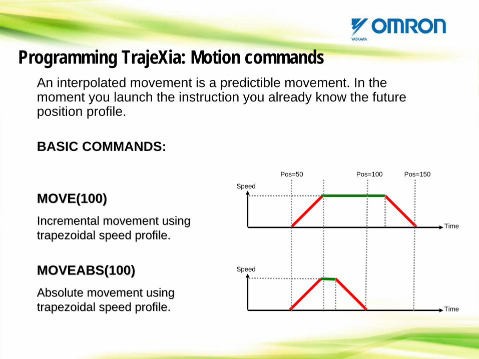
An interpolated movement is a predictible movement. In the moment you launch the instruction you already know the future position profile.
BASIC COMMANDS:
MOVE(100)Incremental movement using trapezoidal speed profile.
MOVE(100)MOVE(100)Incremental movement usingIncremental movement using trapezoidal trapezoidal speed profilespeed profile..
MOVEABS(100)Absolute movement using trapezoidal speed profile.
MOVEABS(100)MOVEABS(100)Absolute movement usingAbsolute movement using trapezoidal trapezoidal speed profilespeed profile..
Speed
Time
Speed
Time
Pos=50 Pos=100 Pos=150
Programming TrajeXia: Motion commands
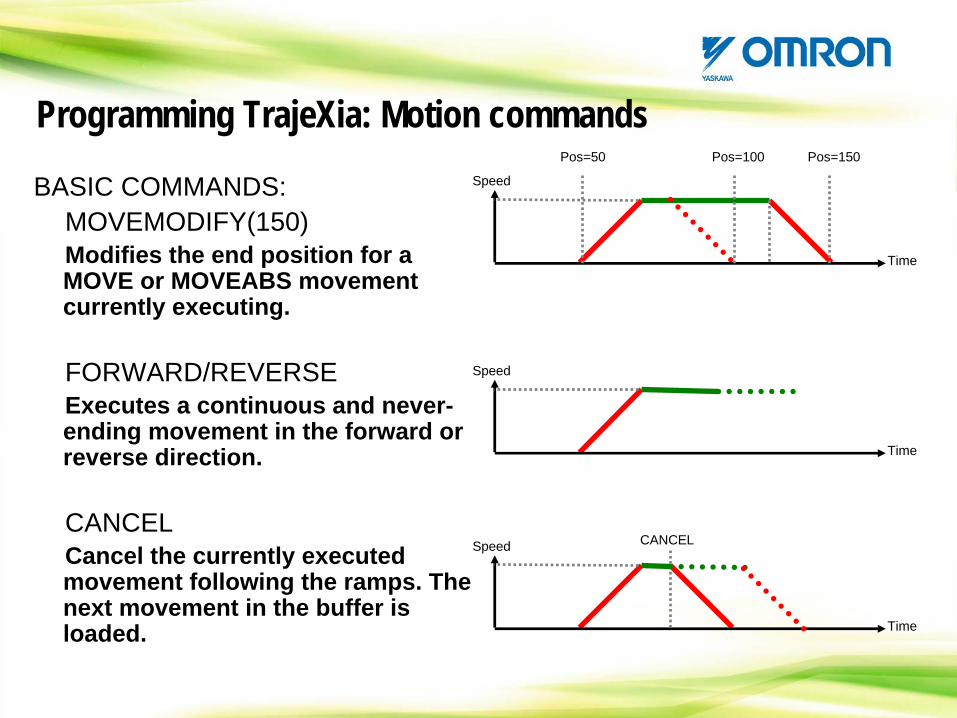
BASIC COMMANDS:MOVEMODIFY(150)Modifies the end position for a MOVE or MOVEABS movement currently executing.
FORWARD/REVERSEExecutes a continuous and never- ending movement in the forward or reverse direction.
CANCELCancel the currently executed movement following the ramps. The next movement in the buffer is loaded.
Speed
Time
Speed
Time
Pos=50 Pos=100 Pos=150
Speed
Time
CANCEL
Programming TrajeXia: Motion commands
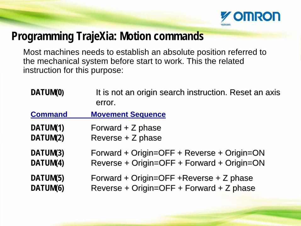
DATUM(0)DATUM(0DATUM(0)) It is not an origin search instruction. Reset an axis error. It is not an origin search instructionIt is not an origin search instruction. . Reset an axisReset an axis error.error.
Command Movement Sequence
DATUM(1) Forward + Z phaseDATUM(2) Reverse + Z phase
DATUM(3) Forward + Origin=OFF + Reverse + Origin=ONDATUM(4) Reverse + Origin=OFF + Forward + Origin=ON
DATUM(5) Forward + Origin=OFF +Reverse + Z phaseDATUM(6) Reverse + Origin=OFF + Forward + Z phase
Command Movement Sequence
DATUM(1) ForwardForward + Z + Z phasephaseDATUM(2) Reverse + Z Reverse + Z phasephase
DATUM(3) ForwardForward + + OriginOrigin=OFF + Reverse + =OFF + Reverse + OriginOrigin=ON=ONDATUM(4) Reverse + Reverse + OriginOrigin=OFF + =OFF + ForwardForward + + OriginOrigin=ON=ON
DATUM(5) ForwardForward + + OriginOrigin=OFF +Reverse + Z =OFF +Reverse + Z phasephaseDATUM(6) Reverse + Reverse + OriginOrigin=OFF + =OFF + ForwardForward + Z + Z phasephase
Most machines needs to establish an absolute position referred to the mechanical system before start to work. This the related instruction for this purpose:
Programming TrajeXia: Motion commands
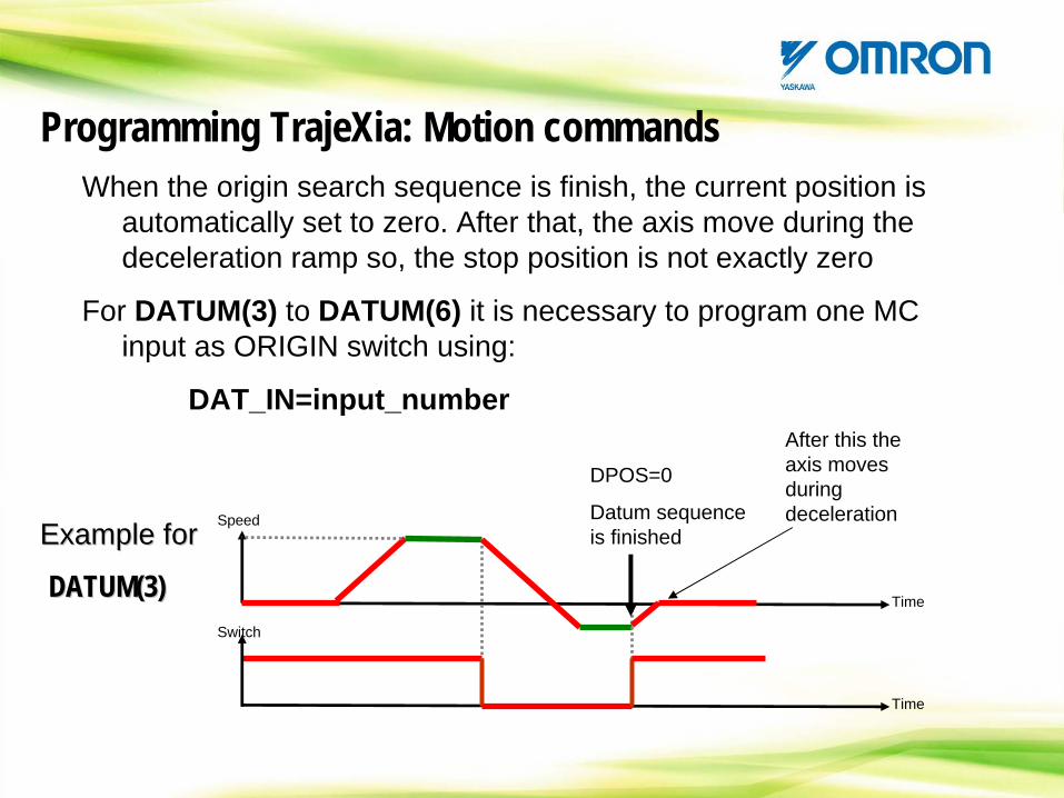
When the origin search sequence is finish, the current position is automatically set to zero. After that, the axis move during the deceleration ramp so, the stop position is not exactly zero
For DATUM(3) to DATUM(6) it is necessary to program one MC input as ORIGIN switch using:
DAT_IN=input_number
Example for
DATUM(3)
Example forExample for
DATUM(3)DATUM(3)
DPOS=0
Datum sequence is finished
Speed
Time
Switch
Time
After this the axis moves during deceleration
Programming TrajeXia: Motion commands
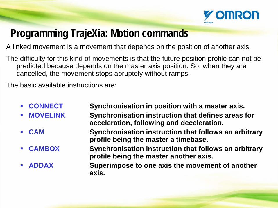
A linked movement is a movement that depends on the position of another axis.
The difficulty for this kind of movements is that the future position profile can not be predicted because depends on the master axis position. So, when they are cancelled, the movement stops abruptely without ramps.
The basic available instructions are:
CONNECT Synchronisation in position with a master axis.MOVELINK Synchronisation instruction that defines areas for
acceleration, following and deceleration.CAM Synchronisation instruction that follows an arbitrary
profile being the master a timebase.CAMBOX Synchronisation instruction that follows an arbitrary
profile being the master another axis.ADDAX Superimpose to one axis the movement of another
axis.
Programming TrajeXia: Motion commands
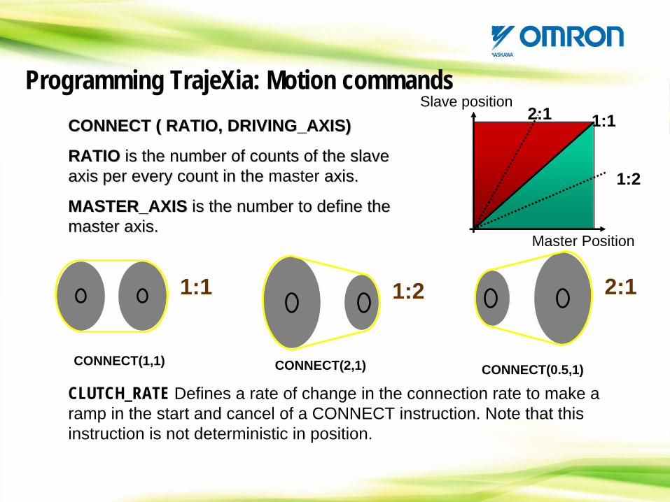
CONNECT ( RATIO, DRIVING_AXIS)
RATIO is the number of counts of the slave axis per every count in the master axis.
MASTER_AXIS is the number to define the master axis.
CONNECT ( RATIO, DRIVING_AXIS)CONNECT ( RATIO, DRIVING_AXIS)
RATIORATIO is the number of counts of the slave is the number of counts of the slave axis per every countaxis per every count in in thethe master axisaxis..
MASTER_AXISMASTER_AXIS is the number tois the number to define define thethe master master axisaxis..
1:1
1:2
2:1
Master Position
Slave position
1:1
CONNECT(1,1)
1:2
CONNECT(2,1)
2:1
CONNECT(0.5,1)
CLUTCH_RATE Defines a rate of change in the connection rate to make a ramp in the start and cancel of a CONNECT instruction. Note that this instruction is not deterministic in position.
CLUTCH_RATE Defines a rate of change in the connection rate to make a ramp in the start and cancel of a CONNECT instruction. Note that this instruction is not deterministic in position.
Programming TrajeXia: Motion commands
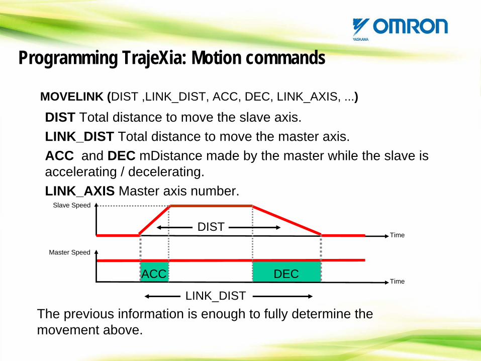
MOVELINK (DIST ,LINK_DIST, ACC, DEC, LINK_AXIS, ...)MOVELINK (DIST ,LINK_DIST, ACC, DEC, LINK_AXIS, ...)
DIST Total distance to move the slave axis.LINK_DIST Total distance to move the master axis.ACC and DEC mDistance made by the master while the slave is accelerating / decelerating. LINK_AXIS Master axis number.
DIST Total distance to move the slave axis.LINK_DIST Total distance to move the master axis.ACC and DEC mDistance made by the master while the slave is accelerating / decelerating.LINK_AXIS Master axis number.
Slave Speed
Time
Master Speed
Time
DIST
LINK_DIST
ACC DEC
The previous information is enough to fully determine the movement above. The previous information is enough to fully determine the movement above.
Programming TrajeXia: Motion commands
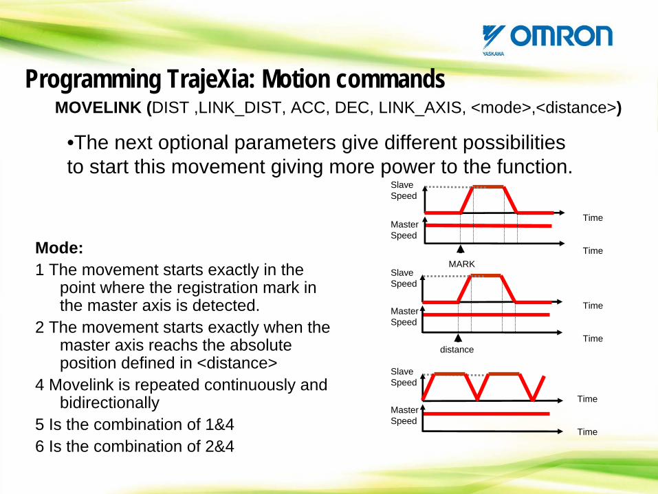
MOVELINK (DIST ,LINK_DIST, ACC, DEC, LINK_AXIS, <mode>,<distance>)MOVELINK (DIST ,LINK_DIST, ACC, DEC, LINK_AXIS, <mode>,<distance>)
•The next optional parameters give different possibilities to start this movement giving more power to the function. •The next optional parameters give different possibilities to start this movement giving more power to the function.
Slave Speed
TimeMaster Speed
TimeMARK
Slave Speed
TimeMaster Speed
Timedistance
Slave Speed
TimeMaster Speed
Time
Mode:1 The movement starts exactly in the
point where the registration mark in the master axis is detected.
2 The movement starts exactly when the master axis reachs the absolute position defined in <distance>
4 Movelink is repeated continuously and bidirectionally
5 Is the combination of 1&46 Is the combination of 2&4
Programming TrajeXia: Motion commands
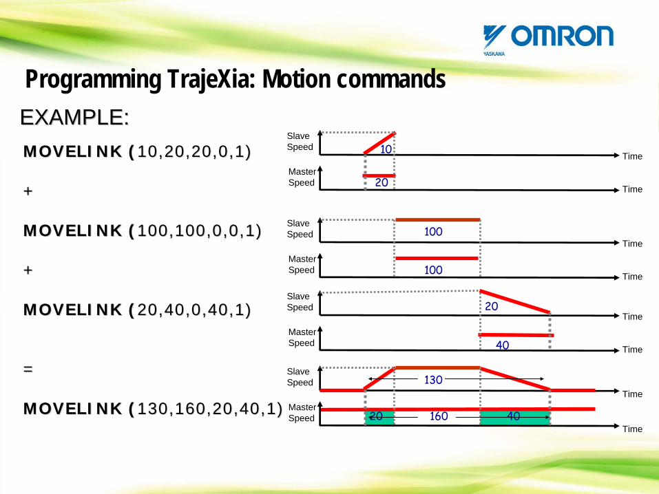
MOVELINK (10,20,20,0,1)
+
MOVELINK (100,100,0,0,1)
+
MOVELINK (20,40,0,40,1)
=
MOVELINK (130,160,20,40,1)
MOVELINK (MOVELINK (10,20,20,0,1)10,20,20,0,1)
++
MOVELINK (MOVELINK (100,100,0,0,1)100,100,0,0,1)
++
MOVELINK (MOVELINK (20,40,0,40,1)20,40,0,40,1)
==
MOVELINK (MOVELINK (130,160,20,40,1)130,160,20,40,1)
Slave Speed
Time
Time
EXAMPLE:EXAMPLE:EXAMPLE:Slave Speed
Master Speed
10
20
Slave Speed
Master Speed
Time
Time100
100
Master Speed
Time
Time20
40
Slave Speed
TimeMaster Speed
Time
130
20 40160
Programming TrajeXia: Motion commands
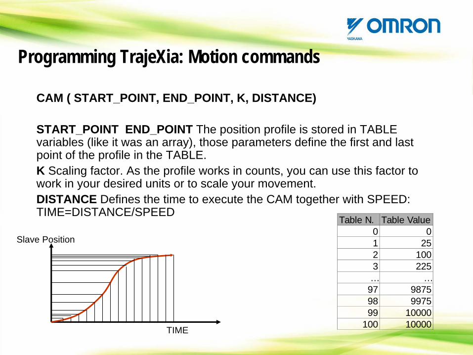
CAM ( START_POINT, END_POINT, K, DISTANCE)
START_POINT END_POINT The position profile is stored in TABLE variables (like it was an array), those parameters define the first and last point of the profile in the TABLE.K Scaling factor. As the profile works in counts, you can use this factor to work in your desired units or to scale your movement.DISTANCE Defines the time to execute the CAM together with SPEED: TIME=DISTANCE/SPEED
Slave Position
TIME
Table N. Table Value0 01 252 1003 225… …97 987598 997599 10000
100 10000
Programming TrajeXia: Motion commands
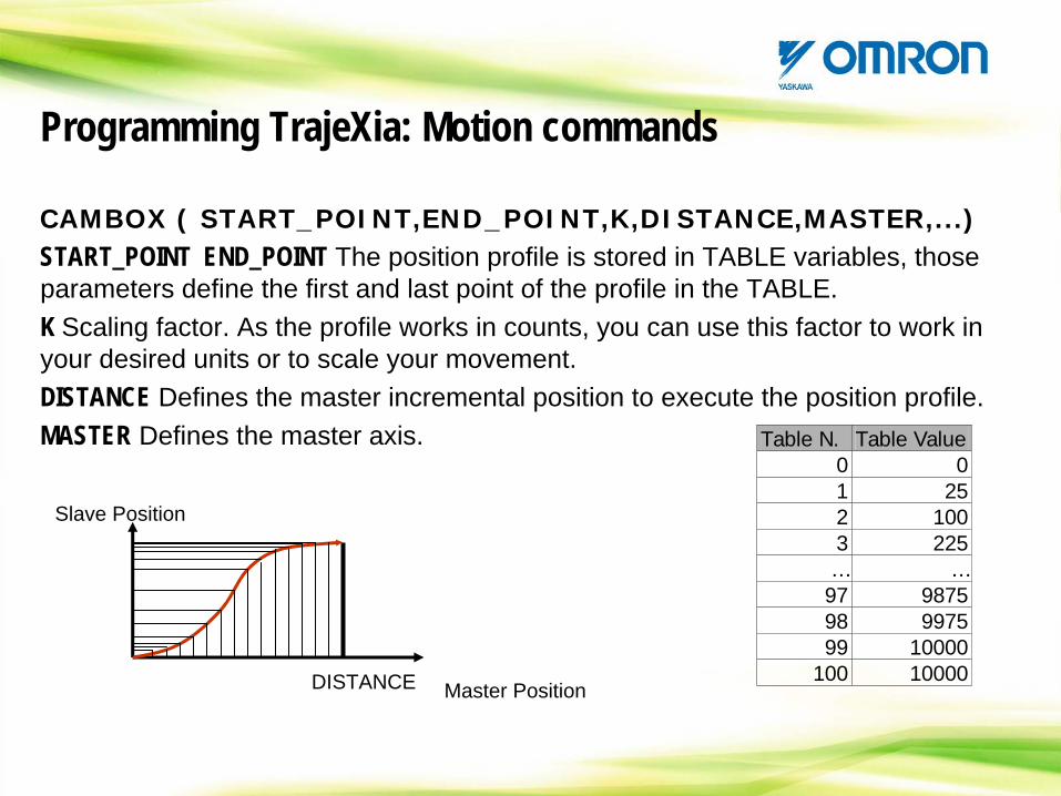
CAMBOX ( START_POINT,END_POINT,K,DISTANCE,MASTER,...)START_POINT END_POINT The position profile is stored in TABLE variables, those parameters define the first and last point of the profile in the TABLE.K Scaling factor. As the profile works in counts, you can use this factor to work in your desired units or to scale your movement.DISTANCE Defines the master incremental position to execute the position profile.MASTER Defines the master axis. Table N. Table Value
0 01 252 1003 225… …97 987598 997599 10000
100 10000
Slave Position
DISTANCE Master Position
Programming TrajeXia: Motion commands
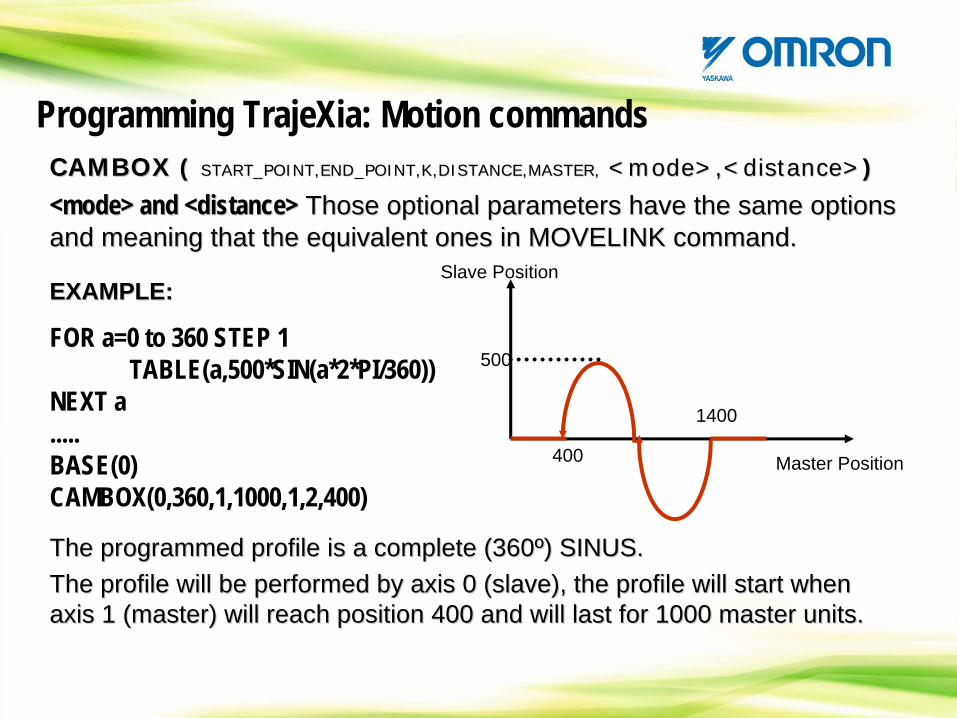
CAMBOX ( START_POINT,END_POINT,K,DISTANCE,MASTER, <mode>,<distance>)CAMBOXCAMBOX ( ( START_POINT,END_POINT,K,DISTANCE,MASTER,START_POINT,END_POINT,K,DISTANCE,MASTER, <<modemode>,<>,<distancedistance>>))
<mode> and <distance> Those optional parameters have the same options and meaning that the equivalent ones in MOVELINK command. <<modemode> > andand <<distancedistance>> Those optional parameters have the same options Those optional parameters have the same options and meaning that the equivalent onesand meaning that the equivalent ones in MOVELINK in MOVELINK commandcommand..
EXAMPLE:EXAMPLE:
FOR a=0 to 360 STEP 1TABLE(a,500*SIN(a*2*PI/360))
NEXT a.....BASE(0)CAMBOX(0,360,1,1000,1,2,400)
The programmed profile is a complete (360º) SINUS.The profile will be performed by axis 0 (slave), the profile will start when axis 1 (master) will reach position 400 and will last for 1000 master units.
The programmed profile isThe programmed profile is a complete (360a complete (360ºº) SINUS.) SINUS.The profile willThe profile will be be performedperformed by by axisaxis 0 (0 (slaveslave), ), the profile will start when the profile will start when axisaxis 1 (master) 1 (master) will reach positionwill reach position 400 400 and will last forand will last for 1000 master 1000 master unitsunits. .
Slave Position
Master Position
500
400
1400
Programming TrajeXia: Motion commands
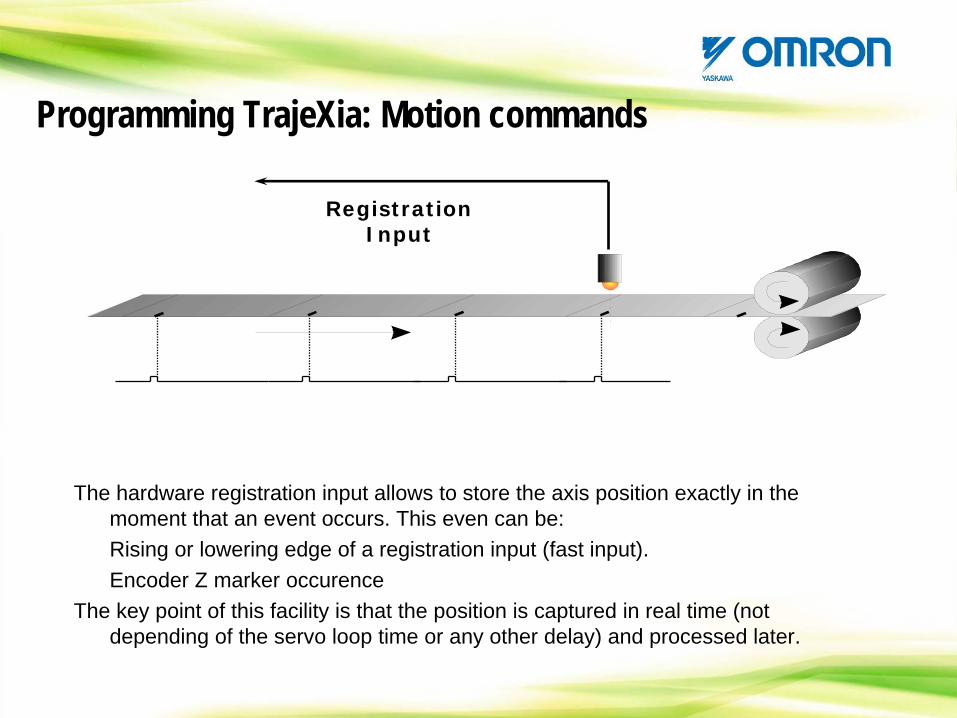
The hardware registration input allows to store the axis position exactly in the moment that an event occurs. This even can be:Rising or lowering edge of a registration input (fast input).Encoder Z marker occurence
The key point of this facility is that the position is captured in real time (not depending of the servo loop time or any other delay) and processed later.
Registration Input
Programming TrajeXia: Motion commands
This instruction is the ‘trigger’ for the registration input. Defines which is the event that will be used to latch the position and prepares the latch for the capture.
In a mechatrolink axis the registration is taken from a fast input in the servodrive. In a Flex-Axes axis, we have two registration inputs per axis.
More details in the next section of this presentation.
REGIST(x)REGIST(x) Hardware registration modeHardware registration mode
Programming TrajeXia: Motion commands
GLOBAL VARIABLES
- VR Memory area is 1024 elements size (static memory)
-TABLE Memory area is up to 64000 elements size (dynamic memory, one TABLE variable exists only from the moment it is used).
Eg. >>TABLE(2450,27) ‘Allocate in memory TABLE(0) to TABLE(2450)
Programming TrajeXia: Variables
VARIABLE DATA FORMAT
There are two data formats in TrajeXia
- Position data (MPOS, DPOS, …) is 32 bit signed integer
- The rest of the data is 32 bit floating point format (24 bit mantissa & 8 bit exponent)
Precaution should be taken with the resolution of the mathematical operation and the conversion to 32 bit integer!!!
Programming TrajeXia: Variables
VR Memory
- Used as global variables in programs.
- Used as Input/output registers in Profibus and DeviceNet communication.
- Used as communication registers with FINS communication.
- Used for data transfer in some mechatrolink axes command (like reading parameter.
- The value is kept at power-off by the battery. It can be saved in EEPROM on request.
Programming TrajeXia: Variables
Table Memory
- Used as global variables in programs.
- Used as communication registers with FINS communication.
- Used as profile data in CAM and CAMBOX .
- Used as data storage in the data trace (oscilloscope)
- The value is kept at power-off by the battery. It can be saved in EEPROM on request.
Programming TrajeXia: Variables
ASSIGNING NAMES TO VR VARIABLESIt is possible to assign names to VR variables and to use those names in all the programs. This makes the project much more readable.
GLOBAL “name”, VR_number
Eg.: you execute next command in one program (it is recommended to do it in the STARTUP program just after power up)
GLOBAL “product_length”,24
From now on you can use the name product_length instead of VR(24) in any other program in your project (not valid for the terminal window).
The use of VR(24) is still valid.
Programming TrajeXia: Variables
ASSIGNING NAMES TO CONSTANT VALUESIt is possible to assign names to constant values and to use those names in all the programs. This makes the project much more readable.
CONSTANT “name”, Value
Eg.: you execute next command in one program (it is recommended to do it in the STARTUP program just after power up)
CONSTANT “end_position”,2000
From now on you can use the name end_position instead of 2000 in any other program in your project (not valid for the terminal window).
Programming TrajeXia: Variables
Note: when you assign CONSTANT and GLOBAL in a program, no other program can be running.
Local Variables
• A local variable is only existing in a particular program.• It is not necessary to declare a global variable in TrajeXia, just using it for the first time allocates this variable.• The variables can have any name but only the first 16 characters are significant.• The variable do not have a definite value so, it is wise to initialize it to a known value
Myvariable=0
Programming TrajeXia: Variables
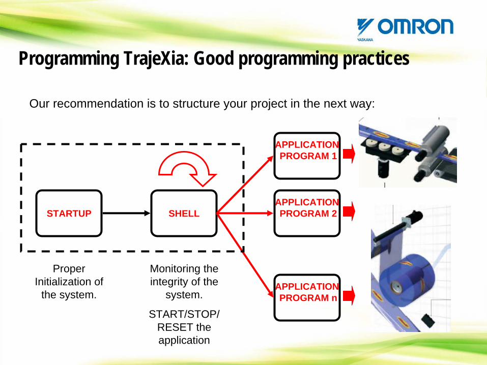
Our recommendation is to structure your project in the next way:
Programming TrajeXia: Good programming practices
STARTUP SHELL
APPLICATIONPROGRAM 1
APPLICATIONPROGRAM 2
APPLICATIONPROGRAM n
Proper Initialization of
the system.
Monitoring the integrity of the
system.
START/STOP/ RESET the application
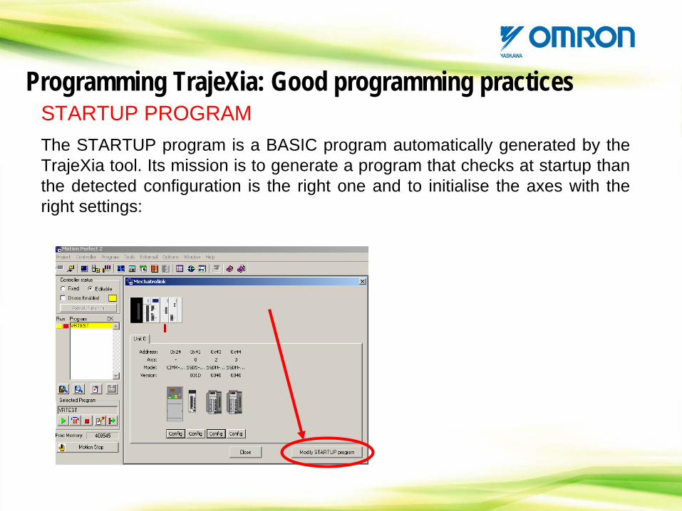
STARTUP PROGRAM The STARTUP program is a BASIC program automatically generated by the TrajeXia tool. Its mission is to generate a program that checks at startup than the detected configuration is the right one and to initialise the axes with the right settings:
Programming TrajeXia: Good programming practices
STARTUP PROGRAM In addition, we recommend that you set here the necessary intitialization of your particular system like:- Axes parameter- Servodrive parameters- GLOBAL/CONSTANT definition- Variable initialization
Programming TrajeXia: Good programming practices
At the end of the STARTUP program you have to start the SHELL program.You have to set the STARTUP as the only program that runs at power-on.
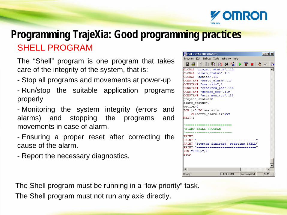
SHELL PROGRAM The “Shell” program is one program that takes care of the integrity of the system, that is:- Stop all programs and movements at power-up- Run/stop the suitable application programs properly- Monitoring the system integrity (errors and alarms) and stopping the programs and movements in case of alarm.- Ensuring a proper reset after correcting the cause of the alarm.- Report the necessary diagnostics.
Programming TrajeXia: Good programming practices
The Shell program must be running in a “low priority” task.The Shell program must not run any axis directly.
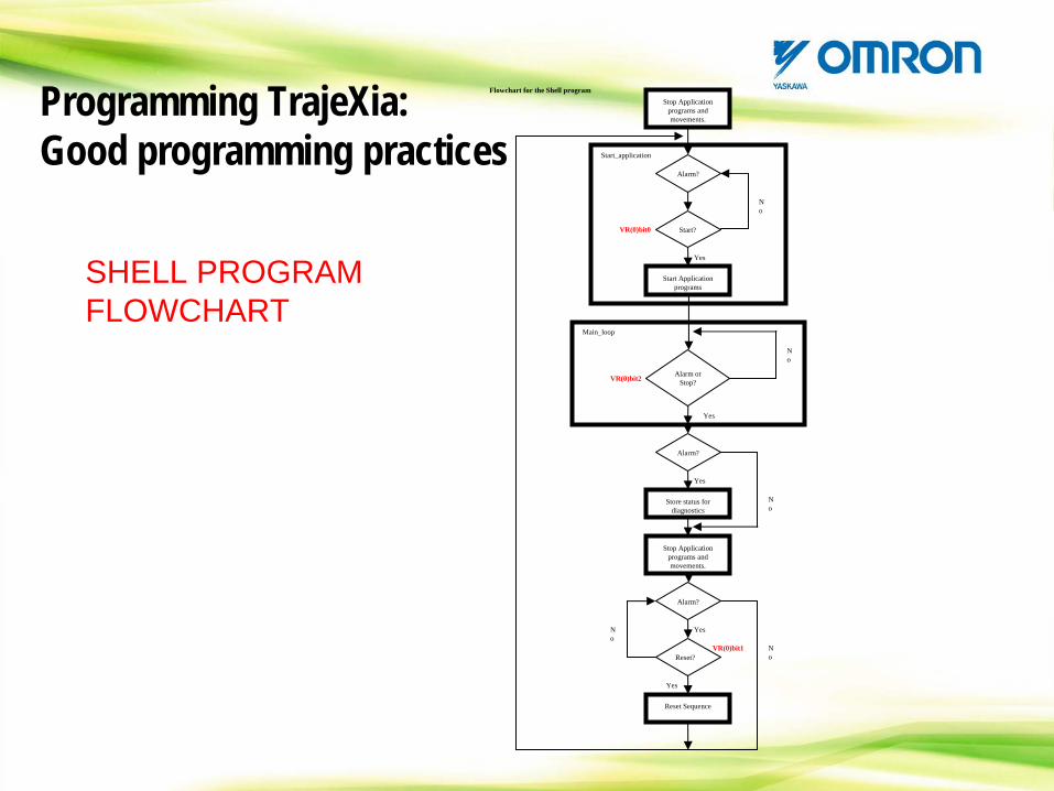
SHELL PROGRAM FLOWCHART
Programming TrajeXia: Good programming practices
Stop Application programs and movements.
Yes
N o
Start Application programs
Alarm?
Start?
N o
Yes
Start_application
Alarm or Stop?
N o
Yes
Main_loop
Alarm?
Store status for diagnostics
Stop Application programs and movements.
Yes
N o
Alarm?
Reset Sequence
Reset?
Flowchart for the Shell program
VR(0)bit0
VR(0)bit1
VR(0)bit2
N o
Yes
CONTENTS
TrajeXia OverviewHardware and general specification TrajeXia ToolsTrajexia ArchitectureProgramming TrajeXiaHow I do… with TrajeXia?CommunicationTrajeXia success historiesApplication discussion
CONTENTS: How I do… with TrajeXia?
-Axis configuration, initialization and tuning-Axes handling-Fault handling-Unit setting according to your application-Homing-Registration-Inverter handling-Using inverter in position control
How I do… with TrajeXia?: Ethernet configuration
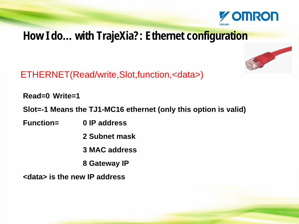
ETHERNET(Read/write,Slot,function,<data>)
Read=0 Write=1
Slot=-1 Means the TJ1-MC16 ethernet (only this option is valid)
Function= 0 IP address
2 Subnet mask
3 MAC address
8 Gateway IP
<data> is the new IP address
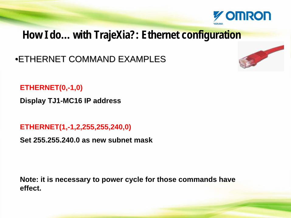
••ETHERNET COMMAND EXAMPLESETHERNET COMMAND EXAMPLES
ETHERNET(0,-1,0)
Display TJ1-MC16 IP address
ETHERNET(1,-1,2,255,255,240,0)
Set 255.255.240.0 as new subnet mask
Note: it is necessary to power cycle for those commands have effect.
How I do… with TrajeXia?: Ethernet configuration
•MECHATROLINK(…) COMMAND
The MECHATROLINK command has been designed to handle with the Mechatrolink master unit and its slaves.
Most of the Mechatrolink commands are handled internally by the system so you do not have to take care.
MECHATROLINK(<Unit>,<function>,[<data>,…])
How I do… with TrajeXia?: Axis configuration.
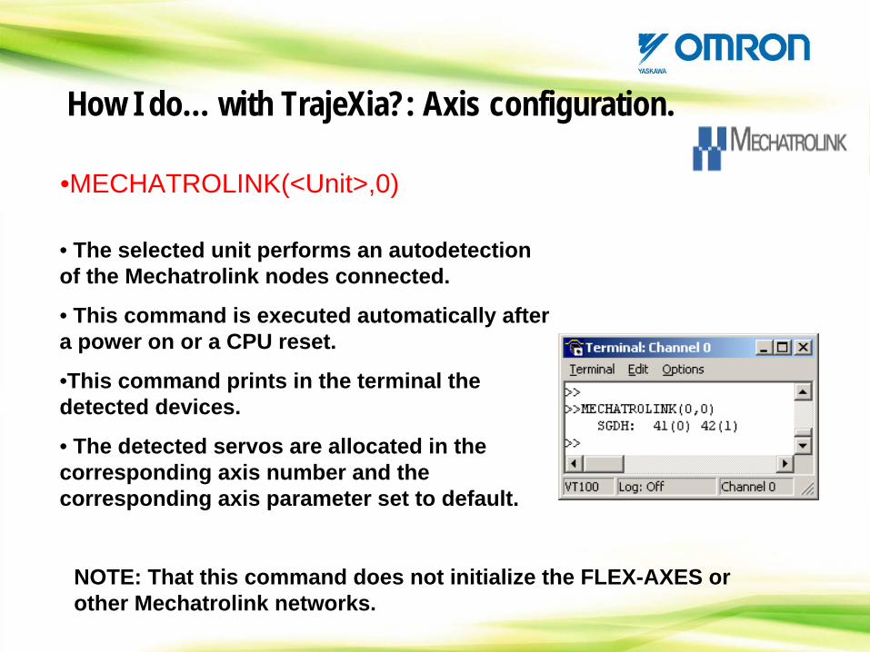
•MECHATROLINK(<Unit>,0)
• The selected unit performs an autodetection of the Mechatrolink nodes connected.
• This command is executed automatically after a power on or a CPU reset.
•This command prints in the terminal the detected devices.
• The detected servos are allocated in the corresponding axis number and the corresponding axis parameter set to default.
How I do… with TrajeXia?: Axis configuration.
NOTE: That this command does not initialize the FLEX-AXES or other Mechatrolink networks.
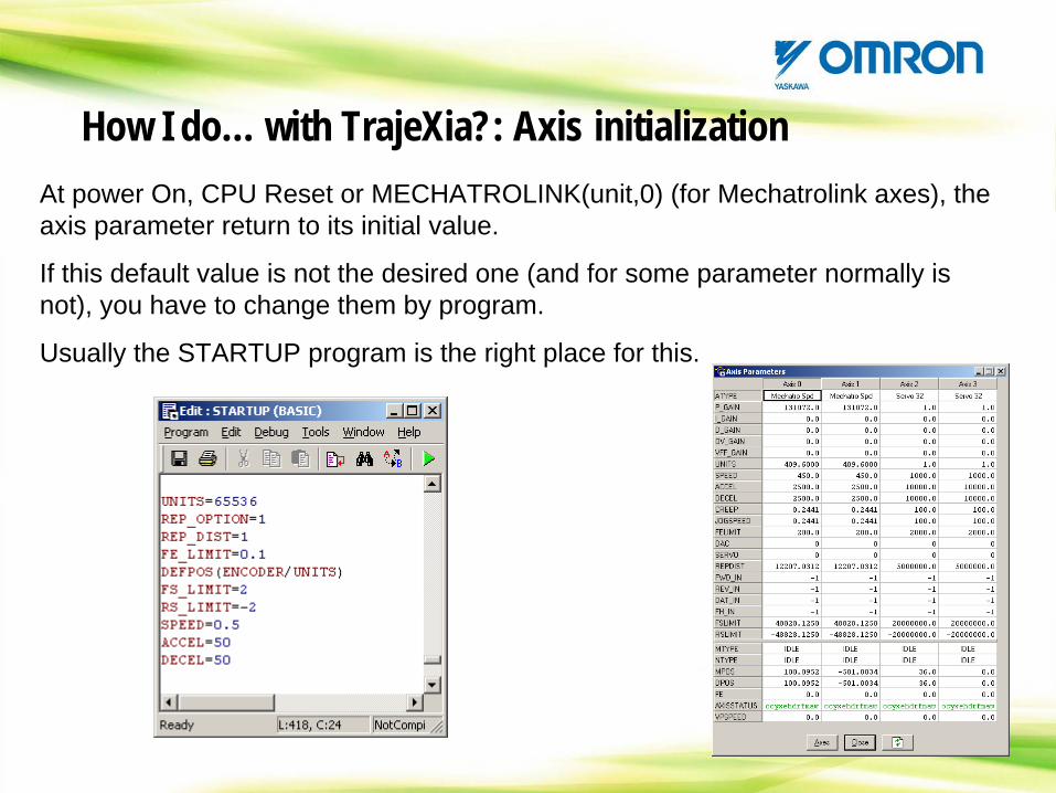
How I do… with TrajeXia?: Axis initializationAt power On, CPU Reset or MECHATROLINK(unit,0) (for Mechatrolink axes), the axis parameter return to its initial value.
If this default value is not the desired one (and for some parameter normally is not), you have to change them by program.
Usually the STARTUP program is the right place for this.
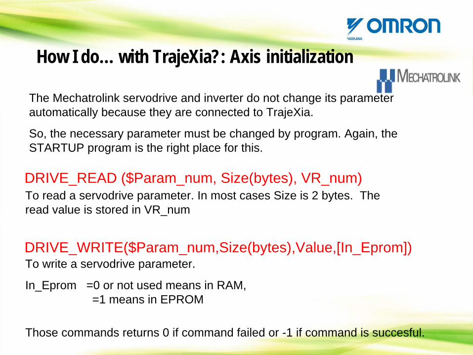
To read a servodrive parameter. In most cases Size is 2 bytes. The read value is stored in VR_num
DRIVE_READ ($Param_num, Size(bytes), VR_num)
DRIVE_WRITE($Param_num,Size(bytes),Value,[In_Eprom])To write a servodrive parameter.
In_Eprom =0 or not used means in RAM, =1 means in EPROM
How I do… with TrajeXia?: Axis initialization
The Mechatrolink servodrive and inverter do not change its parameter automatically because they are connected to TrajeXia.
So, the necessary parameter must be changed by program. Again, the STARTUP program is the right place for this.
Those commands returns 0 if command failed or -1 if command is succesful.
How I do… with TrajeXia?: Axis initialization
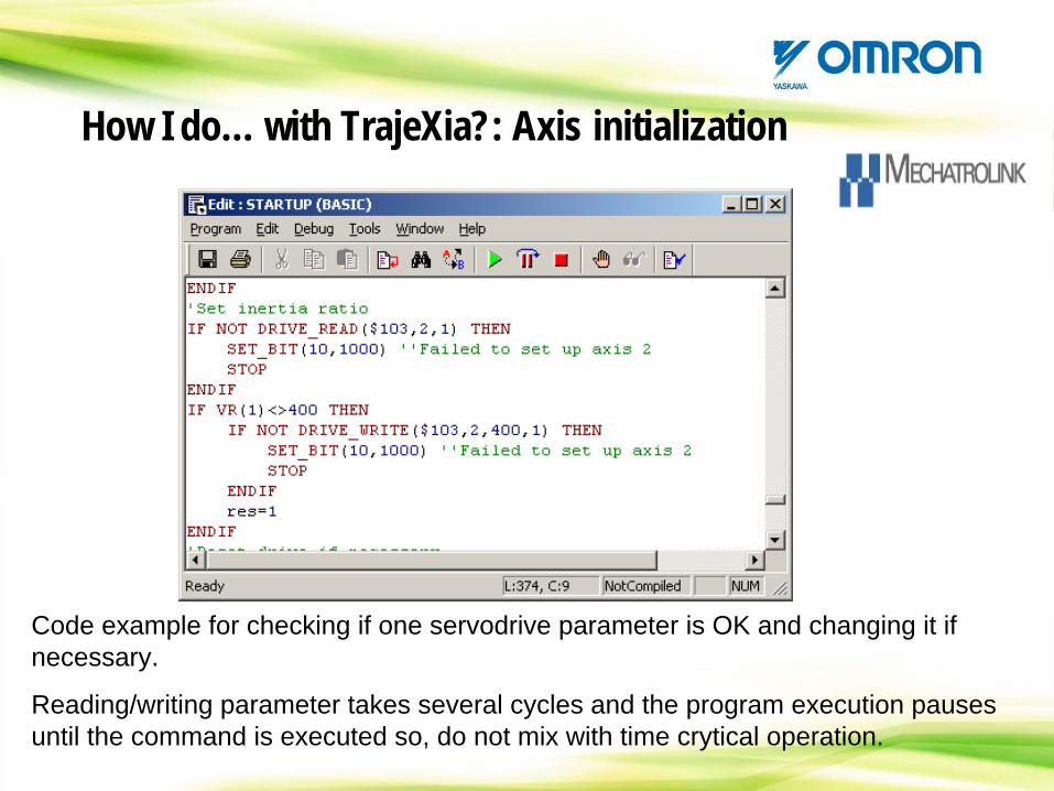
Code example for checking if one servodrive parameter is OK and changing it if necessary.
Reading/writing parameter takes several cycles and the program execution pauses until the command is executed so, do not mix with time crytical operation.
How I do… with TrajeXia?: Axis tuning
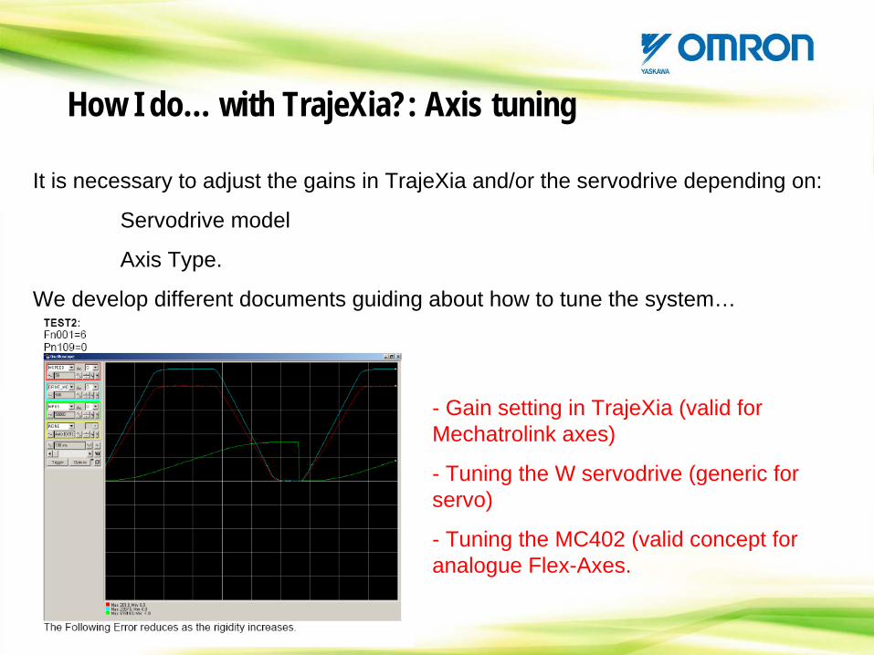
It is necessary to adjust the gains in TrajeXia and/or the servodrive depending on:
Servodrive model
Axis Type.
We develop different documents guiding about how to tune the system…
- Gain setting in TrajeXia (valid for Mechatrolink axes)
- Tuning the W servodrive (generic for servo)
- Tuning the MC402 (valid concept for analogue Flex-Axes.
When making positioning when the servodrive is ATYPE=41 (speed mode), the position gains are set in the TrajeXia CPU. The values in those parameter are very high due to the big value of the DAC (40 000 000H means Max. Speed)
Note that the default value is ok for 13 bit encoders but too high for 17bit encoder or more or for linear motor.
Nevertheless, for position control you expect better dynamics with ATYPE=40. WE STRONGLY RECOMMEND THIS MODE FOR POSITION CONTROL
•P_GAIN•VFF_GAIN
How I do… with TrajeXia?: Tuning
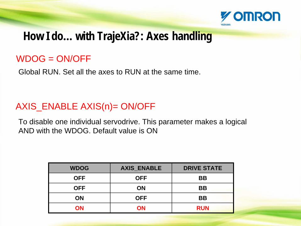
To disable one individual servodrive. This parameter makes a logical AND with the WDOG. Default value is ON
AXIS_ENABLE AXIS(n)= ON/OFF
How I do… with TrajeXia?: Axes handling
WDOG AXIS_ENABLE DRIVE STATEOFF OFF BBOFF ON BBON OFF BBON ON RUN
WDOG = ON/OFFGlobal RUN. Set all the axes to RUN at the same time.
How I do… with TrajeXia?: Axes handling
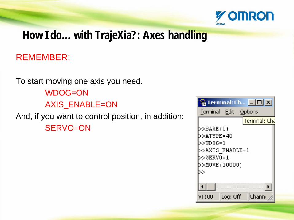
REMEMBER:
To start moving one axis you need.WDOG=ONAXIS_ENABLE=ON
And, if you want to control position, in addition:SERVO=ON
When one axis has one alarm (FE, for example), WDOG=OFF, SERVO=OFF and the movements are cancelled in all axes.
DISABLE_GROUP allows to have this behaviour for group of axes. In one axis of one group has one alarm, the axes of this group are disabled but the other continues normally)
DISABLE_GROUP(-1) breaks all grouping
This is very useful for big machines with different functional parts.
DISABLE_GROUP(ax1, ax2, .. , axn)
How I do… with TrajeXia?: Axes handling
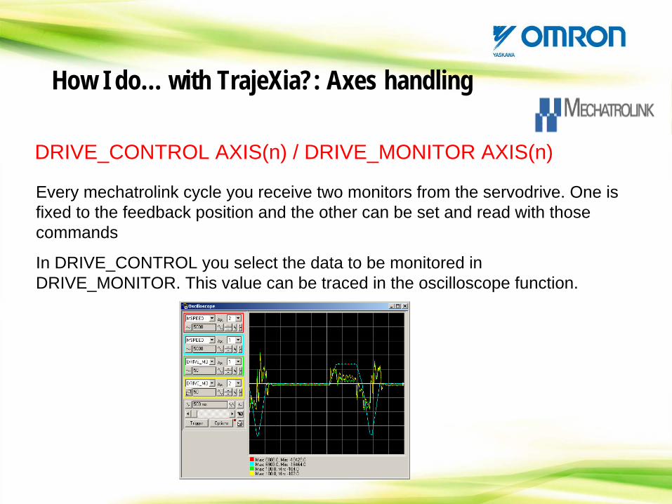
Every mechatrolink cycle you receive two monitors from the servodrive. One is fixed to the feedback position and the other can be set and read with those commands
In DRIVE_CONTROL you select the data to be monitored in DRIVE_MONITOR. This value can be traced in the oscilloscope function.
DRIVE_CONTROL AXIS(n) / DRIVE_MONITOR AXIS(n)
How I do… with TrajeXia?: Axes handling
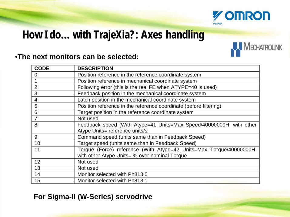
•The next monitors can be selected:CODE DESCRIPTION 0 Position reference in the reference coordinate system 1 Position reference in mechanical coordinate system 2 Following error (this is the real FE when ATYPE=40 is used) 3 Feedback position in the mechanical coordinate system 4 Latch position in the mechanical coordinate system 5 Position reference in the reference coordinate (before filtering) 6 Target position in the reference coordinate system 7 Not used 8 Feedback speed (With Atype=41 Units=Max Speed/40000000H, with other
Atype Units= reference units/s 9 Command speed (units same than in Feedback Speed) 10 Target speed (units same than in Feedback Speed) 11 Torque (Force) reference (With Atype=42 Units=Max Torque/40000000H,
with other Atype Units= % over nominal Torque 12 Not used 13 Not used 14 Monitor selected with Pn813.0 15 Monitor selected with Pn813.1
How I do… with TrajeXia?: Axes handling
For Sigma-II (W-Series) servodrive
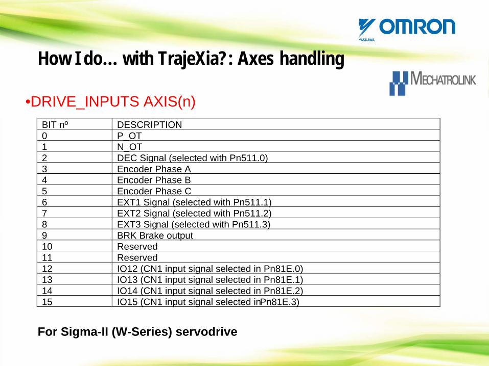
BIT nº DESCRIPTION0 P_OT1 N_OT2 DEC Signal (selected with Pn511.0)3 Encoder Phase A4 Encoder Phase B5 Encoder Phase C6 EXT1 Signal (selected with Pn511.1)7 EXT2 Signal (selected with Pn511.2)8 EXT3 Signal (selected with Pn511.3)9 BRK Brake output10 Reserved11 Reserved12 IO12 (CN1 input signal selected in Pn81E.0)13 IO13 (CN1 input signal selected in Pn81E.1)14 IO14 (CN1 input signal selected in Pn81E.2)15 IO15 (CN1 input signal selected inPn81E.3)
•DRIVE_INPUTS AXIS(n)
How I do… with TrajeXia?: Axes handling
For Sigma-II (W-Series) servodrive
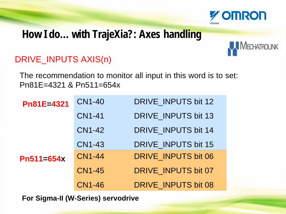
DRIVE_INPUTS AXIS(n)
The recommendation to monitor all input in this word is to set: Pn81E=4321 & Pn511=654x
Pn511=654x
Pn81E=4321 CN1-40 DRIVE_INPUTS bit 12
CN1-41 DRIVE_INPUTS bit 13
CN1-42 DRIVE_INPUTS bit 14
CN1-43 DRIVE_INPUTS bit 15CN1-44 DRIVE_INPUTS bit 06
CN1-45 DRIVE_INPUTS bit 07
CN1-46 DRIVE_INPUTS bit 08
How I do… with TrajeXia?: Axes handling
For Sigma-II (W-Series) servodrive
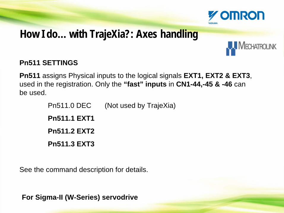
Pn511 SETTINGS
Pn511 assigns Physical inputs to the logical signals EXT1, EXT2 & EXT3, used in the registration. Only the “fast” inputs in CN1-44,-45 & -46 can be used.
Pn511.0 DEC (Not used by TrajeXia)
Pn511.1 EXT1
Pn511.2 EXT2
Pn511.3 EXT3
See the command description for details.
How I do… with TrajeXia?: Axes handling
For Sigma-II (W-Series) servodrive
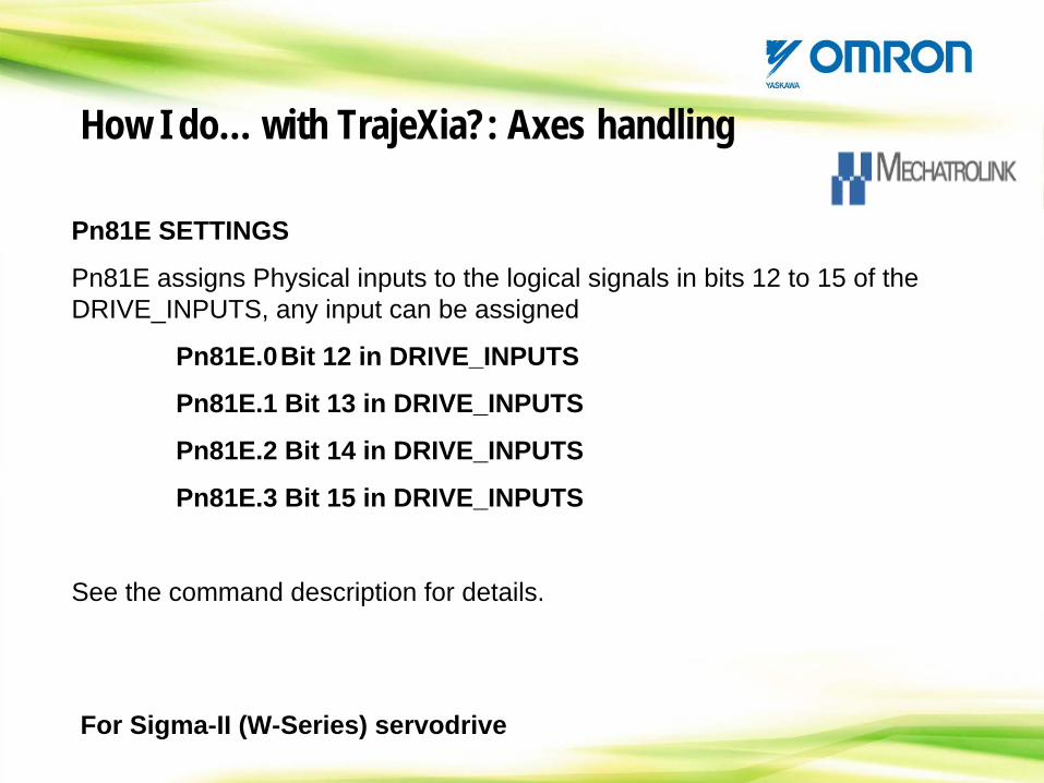
Pn81E SETTINGS
Pn81E assigns Physical inputs to the logical signals in bits 12 to 15 of the DRIVE_INPUTS, any input can be assigned
Pn81E.0Bit 12 in DRIVE_INPUTS
Pn81E.1 Bit 13 in DRIVE_INPUTS
Pn81E.2 Bit 14 in DRIVE_INPUTS
Pn81E.3 Bit 15 in DRIVE_INPUTS
See the command description for details.
For Sigma-II (W-Series) servodrive
How I do… with TrajeXia?: Axes handling
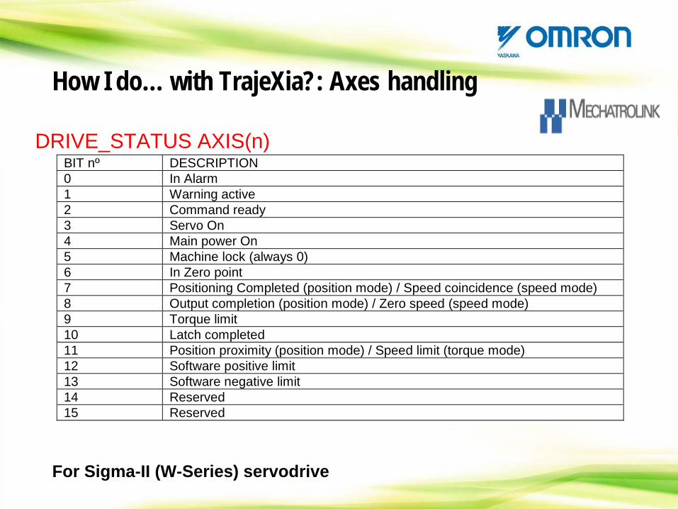
DRIVE_STATUS AXIS(n)BIT nº DESCRIPTION 0 In Alarm 1 Warning active 2 Command ready 3 Servo On 4 Main power On 5 Machine lock (always 0) 6 In Zero point 7 Positioning Completed (position mode) / Speed coincidence (speed mode) 8 Output completion (position mode) / Zero speed (speed mode) 9 Torque limit 10 Latch completed 11 Position proximity (position mode) / Speed limit (torque mode) 12 Software positive limit 13 Software negative limit 14 Reserved 15 Reserved
How I do… with TrajeXia?: Axes handling
For Sigma-II (W-Series) servodrive
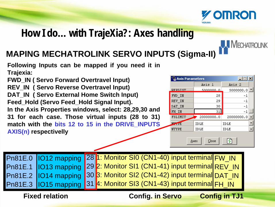
MAPING MECHATROLINK SERVO INPUTS (Sigma-II)Following Inputs can be mapped if you need it in Trajexia:FWD_IN ( Servo Forward Overtravel Input)REV_IN ( Servo Reverse Overtravel Input)DAT_IN ( Servo External Home Switch Input)Feed_Hold (Servo Feed_Hold Signal Input).In the Axis Properties windows, select: 28,29,30 and 31 for each case. Those virtual inputs (28 to 31) match with the bits 12 to 15 in the DRIVE_INPUTS AXIS(n) respectivelly
1: Monitor SI0 (CN1-40) input terminal2: Monitor SI1 (CN1-41) input terminal3: Monitor SI2 (CN1-42) input terminal4: Monitor SI3 (CN1-43) input terminal
FW_INREV_INDAT_INFH_IN
Pn81E.0 IO12 mappingPn81E.1 IO13 mappingPn81E.2 IO14 mappingPn81E.3 IO15 mapping
Fixed relation
28293031
Config. in Servo Config in TJ1
How I do… with TrajeXia?: Axes handling
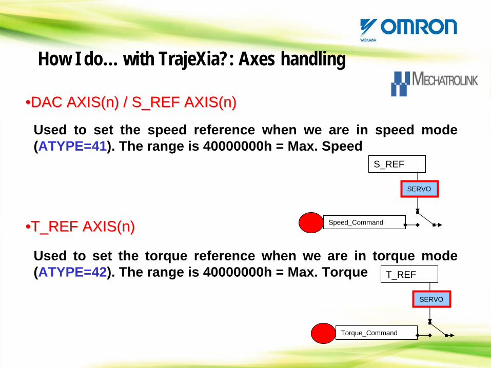
••DAC AXIS(n) / S_REF AXIS(n)DAC AXIS(n) / S_REF AXIS(n)
Used to set the speed reference when we are in speed mode (ATYPE=41). The range is 40000000h = Max. Speed
••T_REF AXIS(n)T_REF AXIS(n)
Used to set the torque reference when we are in torque mode (ATYPE=42). The range is 40000000h = Max. Torque
S_REF
SERVO
Speed_Command
T_REF
SERVO
Torque_Command
How I do… with TrajeXia?: Axes handling
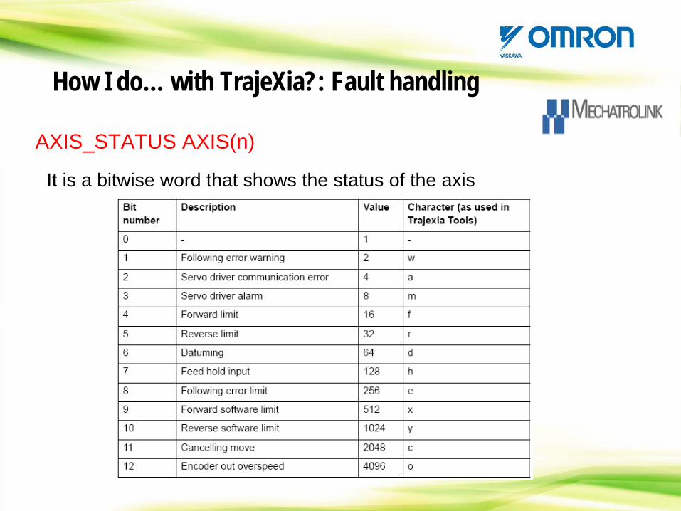
AXIS_STATUS AXIS(n)
It is a bitwise word that shows the status of the axis
How I do… with TrajeXia?: Fault handling
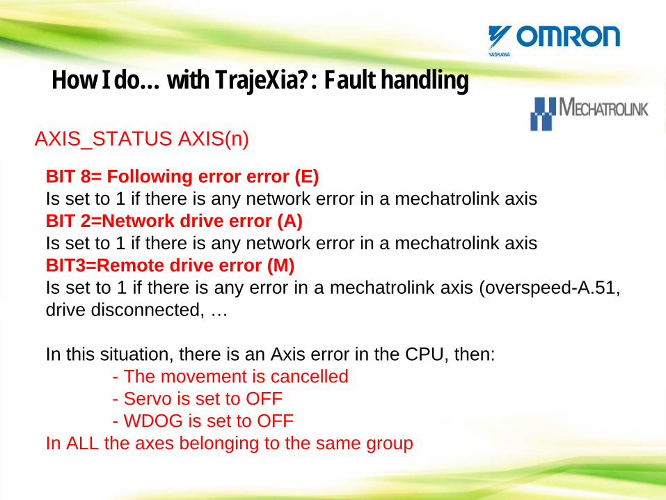
AXIS_STATUS AXIS(n)
BIT 8= Following error error (E)Is set to 1 if there is any network error in a mechatrolink axisBIT 2=Network drive error (A)Is set to 1 if there is any network error in a mechatrolink axisBIT3=Remote drive error (M)Is set to 1 if there is any error in a mechatrolink axis (overspeed-A.51, drive disconnected, …
In this situation, there is an Axis error in the CPU, then:- The movement is cancelled- Servo is set to OFF- WDOG is set to OFF
In ALL the axes belonging to the same group
How I do… with TrajeXia?: Fault handling
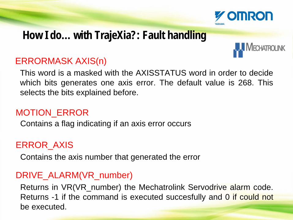
ERRORMASK AXIS(n)This word is a masked with the AXISSTATUS word in order to decide which bits generates one axis error. The default value is 268. This selects the bits explained before.
How I do… with TrajeXia?: Fault handling
MOTION_ERROR
ERROR_AXIS
Contains a flag indicating if an axis error occurs
Contains the axis number that generated the error
DRIVE_ALARM(VR_number)Returns in VR(VR_number) the Mechatrolink Servodrive alarm code. Returns -1 if the command is executed succesfully and 0 if could not be executed.
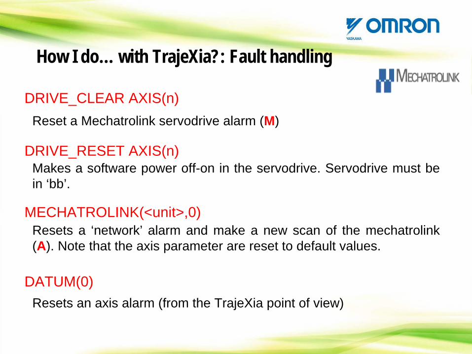
DRIVE_CLEAR AXIS(n)Reset a Mechatrolink servodrive alarm (M)
DRIVE_RESET AXIS(n)
MECHATROLINK(<unit>,0)
DATUM(0)
Makes a software power off-on in the servodrive. Servodrive must be in ‘bb’.
Resets a ‘network’ alarm and make a new scan of the mechatrolink (A). Note that the axis parameter are reset to default values.
Resets an axis alarm (from the TrajeXia point of view)
How I do… with TrajeXia?: Fault handling
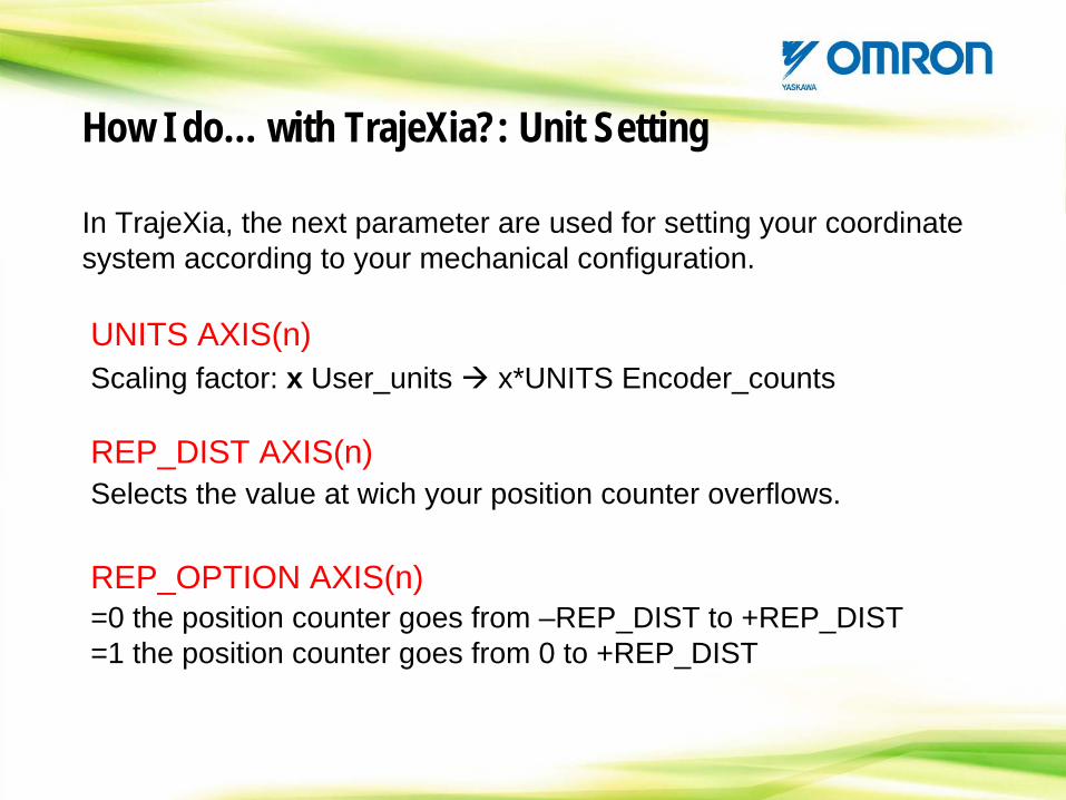
How I do… with TrajeXia?: Unit Setting
In TrajeXia, the next parameter are used for setting your coordinate system according to your mechanical configuration.
UNITS AXIS(n)
REP_DIST AXIS(n)
REP_OPTION AXIS(n)
Scaling factor: x User_units x*UNITS Encoder_counts
Selects the value at wich your position counter overflows.
=0 the position counter goes from –REP_DIST to +REP_DIST=1 the position counter goes from 0 to +REP_DIST
With a mechatrolink axis, the Servodrive gear ratio is affecting to the units as follows:
1Unit command = 1 UNITS * Pn202 / Pn203 for the Sigma-II (WT)1Unit command = 1 UNITS * Pn20E / Pn210 for the Junma and Sigma-
III (WN)
So now it is possible to work with Gear ratio with infinite decimals like 1 : 27/3
Note that factory parameter of Pn202=4!!!
Note that the encoder resolution seen from Trajexia changes according to Pn202 and Pn203 so, it is not recommended to set values where: Pn202>>Pn203
How I do… with TrajeXia?: Unit setting
With a Flexible axis, use ENCODER_RATIO(Num,Den) instead of Pn202 and Pn203
1Unit command = 1 UNITS * Num / Den
And you obtain similar results than for the Mechatrolink axes.
How I do… with TrajeXia?: Unit setting
•When an absolute encoder is used in an axis with a limited running distance, simply set Pn205 (Multiturn limit setting) and REP_DIST to a value higher than the running distance of the motor.
•When the axis is running always in the same direction (like feeders), we have to set the parameter in such a way that the overflow occurs exactly in the same position in the servodrive and in the TrajeXia.
How I do… with TrajeXia?: Unit setting
HANDS ON
SETUP demo Units
How I do… with TrajeXia?: Unit setting
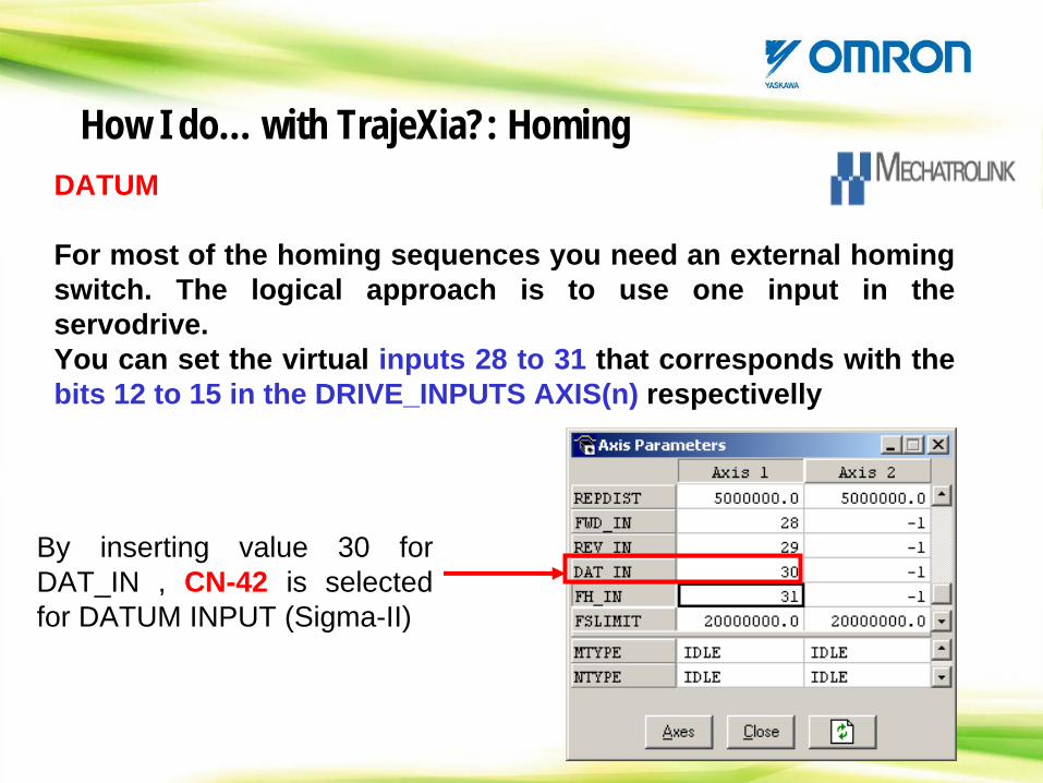
DATUM
For most of the homing sequences you need an external homing switch. The logical approach is to use one input in the servodrive.You can set the virtual inputs 28 to 31 that corresponds with the bits 12 to 15 in the DRIVE_INPUTS AXIS(n) respectivelly
By inserting value 30 for DAT_IN , CN-42 is selected for DATUM INPUT (Sigma-II)
How I do… with TrajeXia?: Homing
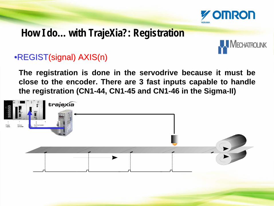
••REGISTREGIST(signal) AXIS(n)(signal) AXIS(n)
The registration is done in the servodrive because it must be close to the encoder. There are 3 fast inputs capable to handle the registration (CN1-44, CN1-45 and CN1-46 in the Sigma-II)
How I do… with TrajeXia?: Registration
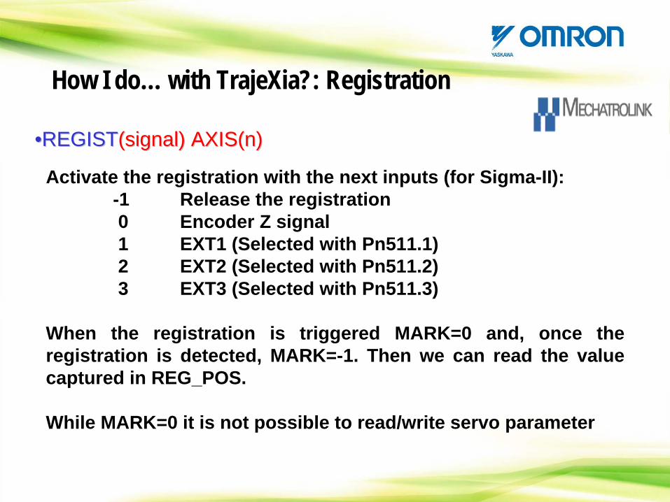
••REGISTREGIST(signal) AXIS(n)(signal) AXIS(n)
Activate the registration with the next inputs (for Sigma-II):-1 Release the registration0 Encoder Z signal1 EXT1 (Selected with Pn511.1)2 EXT2 (Selected with Pn511.2)3 EXT3 (Selected with Pn511.3)
When the registration is triggered MARK=0 and, once the registration is detected, MARK=-1. Then we can read the value captured in REG_POS.
While MARK=0 it is not possible to read/write servo parameter
How I do… with TrajeXia?: Registration
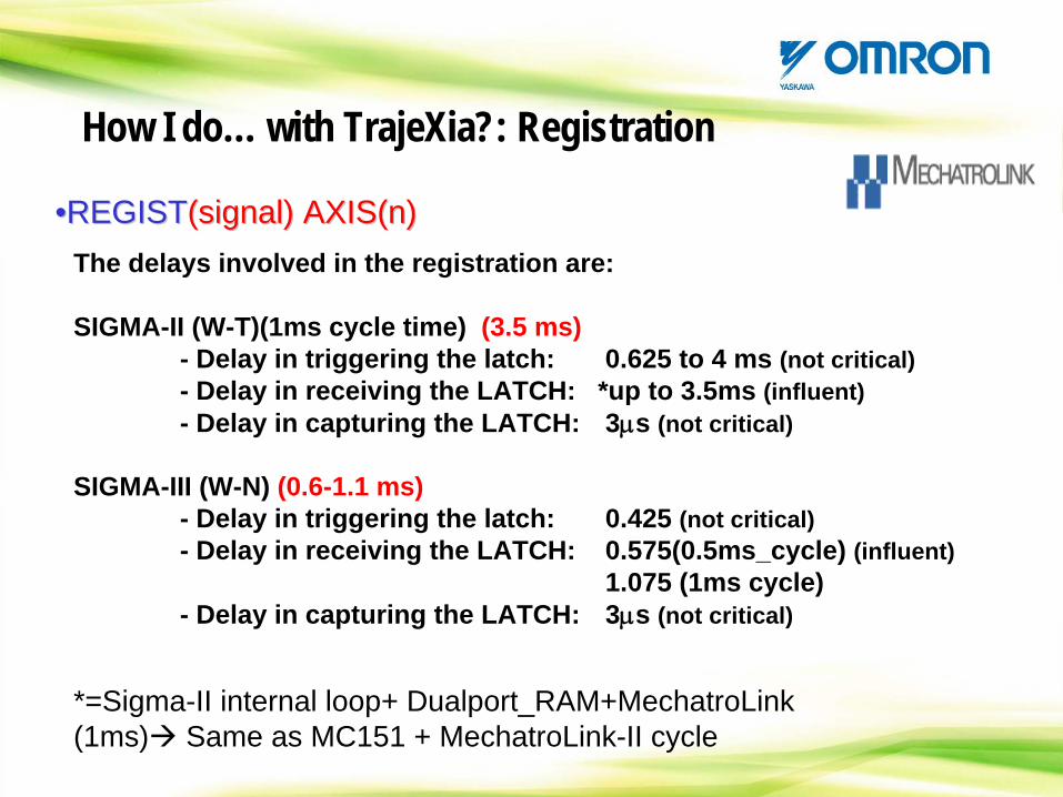
••REGISTREGIST(signal) AXIS(n)(signal) AXIS(n)The delays involved in the registration are:
SIGMA-II (W-T)(1ms cycle time) (3.5 ms)- Delay in triggering the latch: 0.625 to 4 ms (not critical)- Delay in receiving the LATCH: *up to 3.5ms (influent)- Delay in capturing the LATCH: 3μs (not critical)
SIGMA-III (W-N) (0.6-1.1 ms)- Delay in triggering the latch: 0.425 (not critical)- Delay in receiving the LATCH: 0.575(0.5ms_cycle) (influent)
1.075 (1ms cycle)- Delay in capturing the LATCH: 3μs (not critical)
*=Sigma-II internal loop+ Dualport_RAM+MechatroLink (1ms) Same as MC151 + MechatroLink-II cycle
How I do… with TrajeXia?: Registration
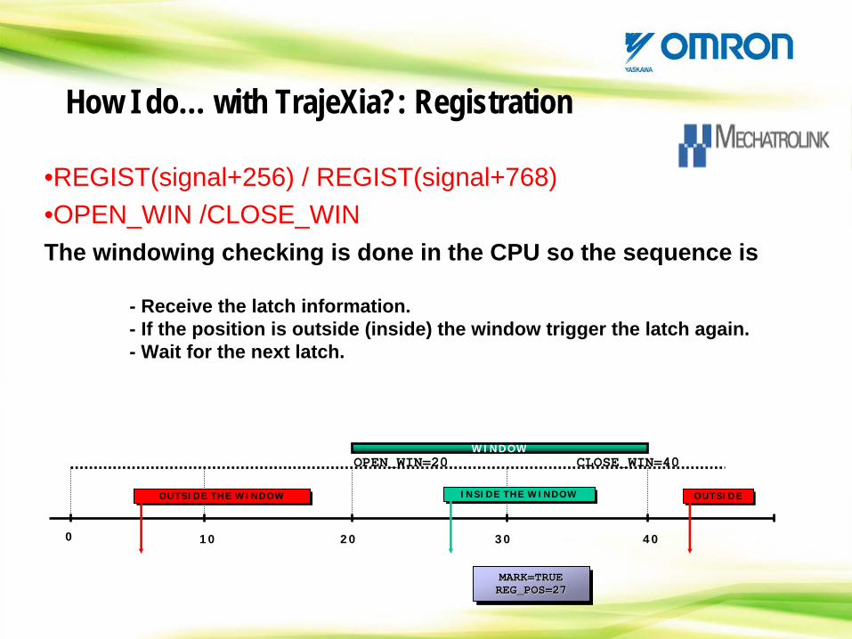
•REGIST(signal+256) / REGIST(signal+768)•OPEN_WIN /CLOSE_WINThe windowing checking is done in the CPU so the sequence is
- Receive the latch information.- If the position is outside (inside) the window trigger the latch again.- Wait for the next latch.
0 20
OUTSIDE THE WINDOWOUTSIDE THE WINDOW
OPEN_WIN=20WINDOW
4010 30
CLOSE_WIN=40
INSIDE THE WINDOWINSIDE THE WINDOW OUTSIDEOUTSIDE
MARK=TRUEREG_POS=27MARK=TRUEMARK=TRUE
REG_POS=27REG_POS=27
How I do… with TrajeXia?: Registration
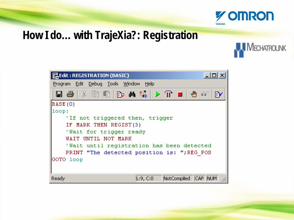
How I do… with TrajeXia?: Registration
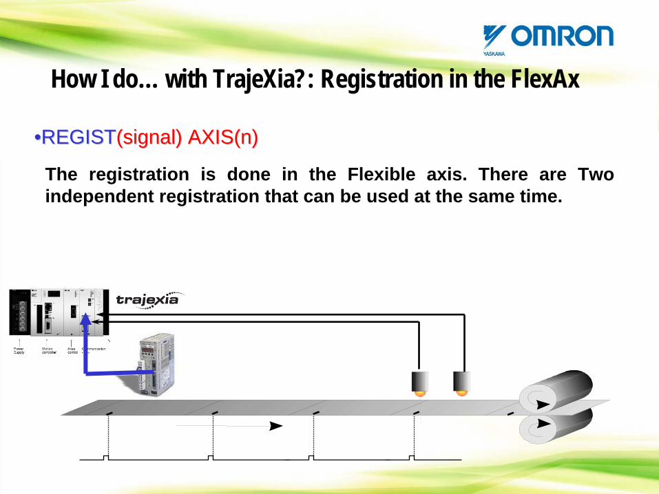
••REGISTREGIST(signal) AXIS(n)(signal) AXIS(n)
The registration is done in the Flexible axis. There are Two independent registration that can be used at the same time.
How I do… with TrajeXia?: Registration in the FlexAx
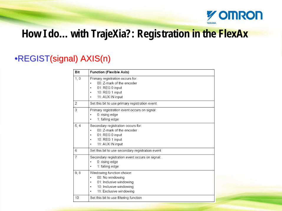
••REGISTREGIST(signal) AXIS(n)(signal) AXIS(n)
How I do… with TrajeXia?: Registration in the FlexAx
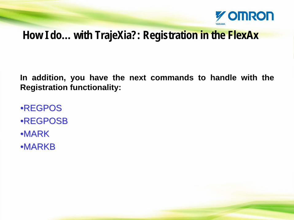
••REGPOSREGPOS••REGPOSBREGPOSB••MARKMARK••MARKBMARKB
How I do… with TrajeXia?: Registration in the FlexAx
In addition, you have the next commands to handle with the Registration functionality:
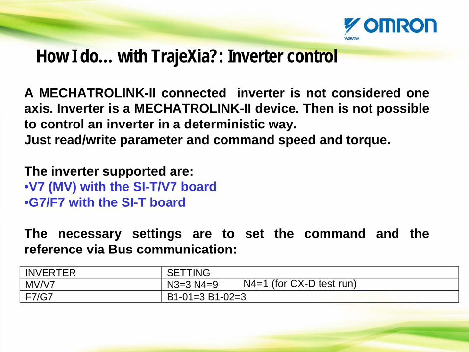
A MECHATROLINK-II connected inverter is not considered one axis. Inverter is a MECHATROLINK-II device. Then is not possible to control an inverter in a deterministic way. Just read/write parameter and command speed and torque.
The inverter supported are:•V7 (MV) with the SI-T/V7 board•G7/F7 with the SI-T board
The necessary settings are to set the command and the reference via Bus communication:INVERTER SETTING MV/V7 N3=3 N4=9 F7/G7 B1-01=3 B1-02=3
N4=1 (for CX-D test run)
How I do… with TrajeXia?: Inverter control
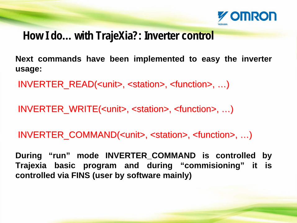
Next commands have been implemented to easy the inverter usage:
INVERTER_READ(<unit>, <station>, <function>, INVERTER_READ(<unit>, <station>, <function>, ……) )
INVERTER_WRITE(<unit>, <station>, <function>, INVERTER_WRITE(<unit>, <station>, <function>, ……) )
INVERTER_COMMAND(<unit>, <station>, <function>, INVERTER_COMMAND(<unit>, <station>, <function>, ……) )
During “run” mode INVERTER_COMMAND is controlled by Trajexia basic program and during “commisioning” it is controlled via FINS (user by software mainly)
How I do… with TrajeXia?: Inverter control
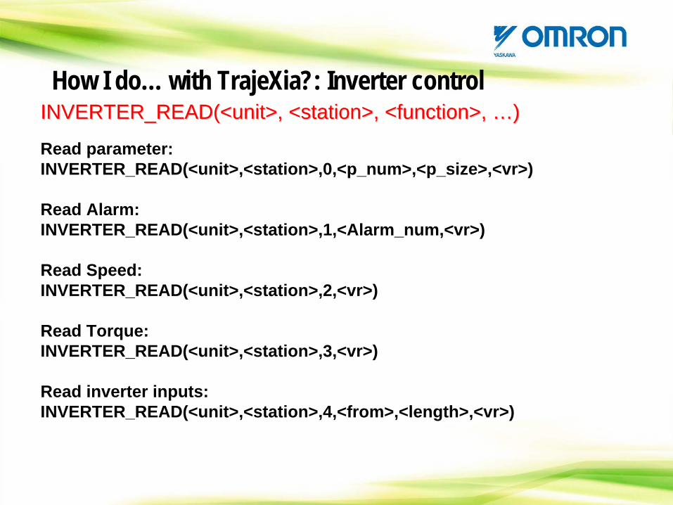
INVERTER_READ(<unit>, <station>, <function>, INVERTER_READ(<unit>, <station>, <function>, ……) )
Read parameter:INVERTER_READ(<unit>,<station>,0,<p_num>,<p_size>,<vr>)
Read Alarm:INVERTER_READ(<unit>,<station>,1,<Alarm_num,<vr>)
Read Speed:INVERTER_READ(<unit>,<station>,2,<vr>)
Read Torque:INVERTER_READ(<unit>,<station>,3,<vr>)
Read inverter inputs:INVERTER_READ(<unit>,<station>,4,<from>,<length>,<vr>)
How I do… with TrajeXia?: Inverter control
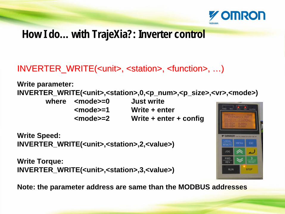
INVERTER_WRITE(<unit>, <station>, <function>, INVERTER_WRITE(<unit>, <station>, <function>, ……) )
Write parameter:INVERTER_WRITE(<unit>,<station>,0,<p_num>,<p_size>,<vr>,<mode>)
where <mode>=0 Just write<mode>=1 Write + enter<mode>=2 Write + enter + config
Write Speed:INVERTER_WRITE(<unit>,<station>,2,<value>)
Write Torque:INVERTER_WRITE(<unit>,<station>,3,<value>)
Note: the parameter address are same than the MODBUS addresses
How I do… with TrajeXia?: Inverter control
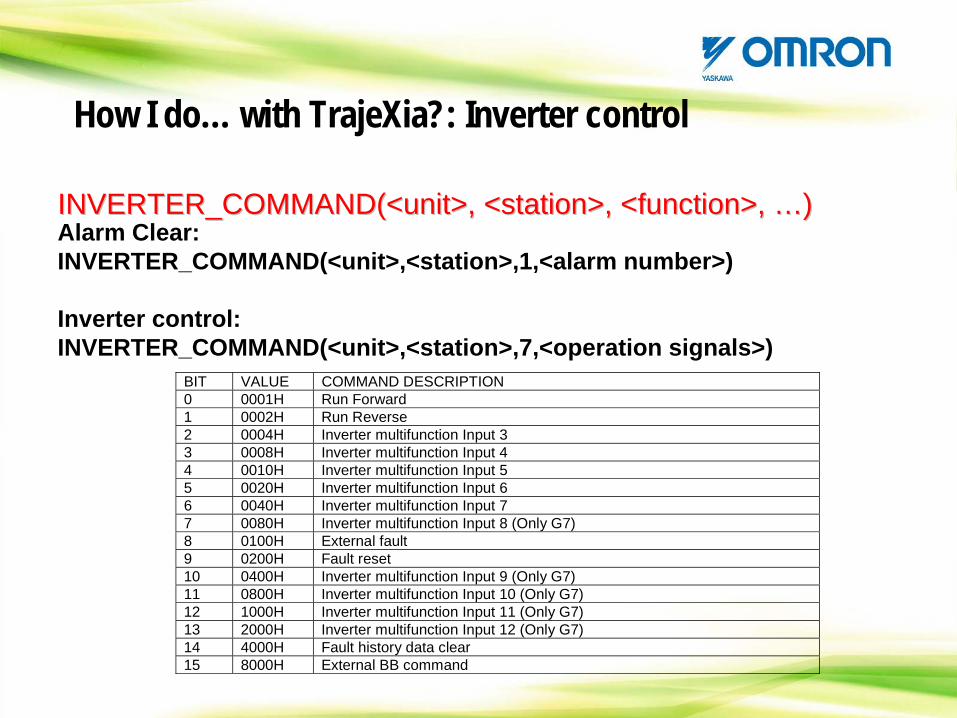
INVERTER_COMMAND(<unit>, <station>, <function>, INVERTER_COMMAND(<unit>, <station>, <function>, ……) ) Alarm Clear:INVERTER_COMMAND(<unit>,<station>,1,<alarm number>)
Inverter control:INVERTER_COMMAND(<unit>,<station>,7,<operation signals>)
BIT VALUE COMMAND DESCRIPTION 0 0001H Run Forward 1 0002H Run Reverse 2 0004H Inverter multifunction Input 3 3 0008H Inverter multifunction Input 4 4 0010H Inverter multifunction Input 5 5 0020H Inverter multifunction Input 6 6 0040H Inverter multifunction Input 7 7 0080H Inverter multifunction Input 8 (Only G7) 8 0100H External fault 9 0200H Fault reset 10 0400H Inverter multifunction Input 9 (Only G7) 11 0800H Inverter multifunction Input 10 (Only G7) 12 1000H Inverter multifunction Input 11 (Only G7) 13 2000H Inverter multifunction Input 12 (Only G7) 14 4000H Fault history data clear 15 8000H External BB command
How I do… with TrajeXia?: Inverter control
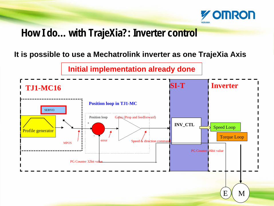
How I do… with TrajeXia?: Inverter control
It is possible to use a Mechatrolink inverter as one TrajeXia Axis
Initial implementation already done
Profile generator
+
-
Position loop
MPOS
PG Counter 16bit value
error Speed & direction command
Gains (Prop and feedforward)
INV_CTL Speed Loop
Torque Loop
ME
TJ1-MC16 SI-T Inverter
SERVO
Position loop in TJ1-MC
PG Counter 32bit value
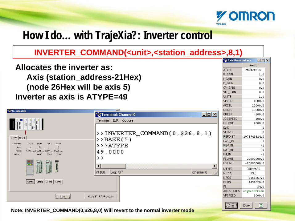
How I do… with TrajeXia?: Inverter control
Allocates the inverter as:Axis (station_address-21Hex)(node 26Hex will be axis 5)
Inverter as axis is ATYPE=49
INVERTER_COMMAND(<unit>,<station_address>,8,1)
Note: INVERTER_COMMAND(0,$26,8,0) Will revert to the normal inverter mode
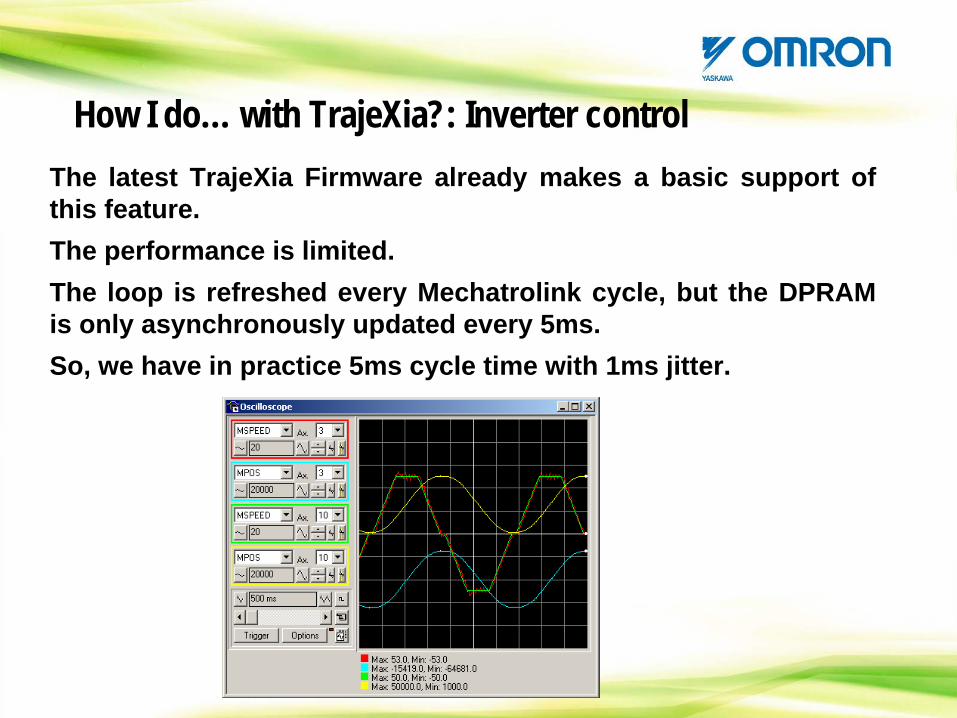
How I do… with TrajeXia?: Inverter controlThe latest TrajeXia Firmware already makes a basic support of this feature.The performance is limited.The loop is refreshed every Mechatrolink cycle, but the DPRAM is only asynchronously updated every 5ms.So, we have in practice 5ms cycle time with 1ms jitter.
CONTENTS
TrajeXia OverviewHardware and general specification TrajeXia ToolsTrajexia ArchitectureProgramming TrajeXiaHow I do… with TrajeXia?CommunicationTrajeXia success histories
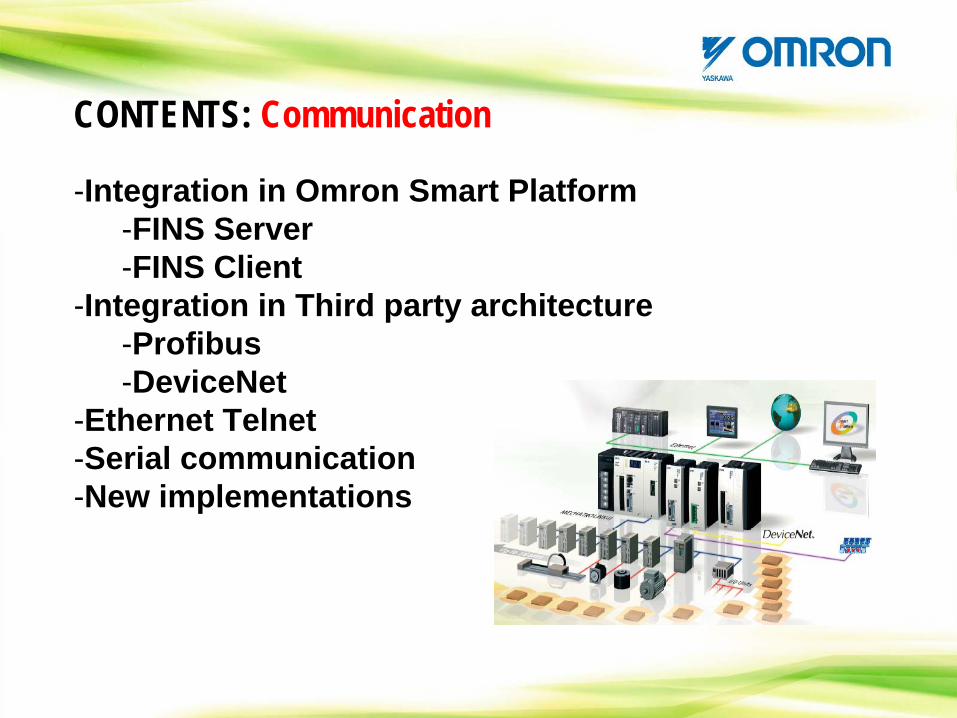
CONTENTS: Communication
-Integration in Omron Smart Platform-FINS Server-FINS Client
-Integration in Third party architecture-Profibus-DeviceNet
-Ethernet Telnet-Serial communication-New implementations
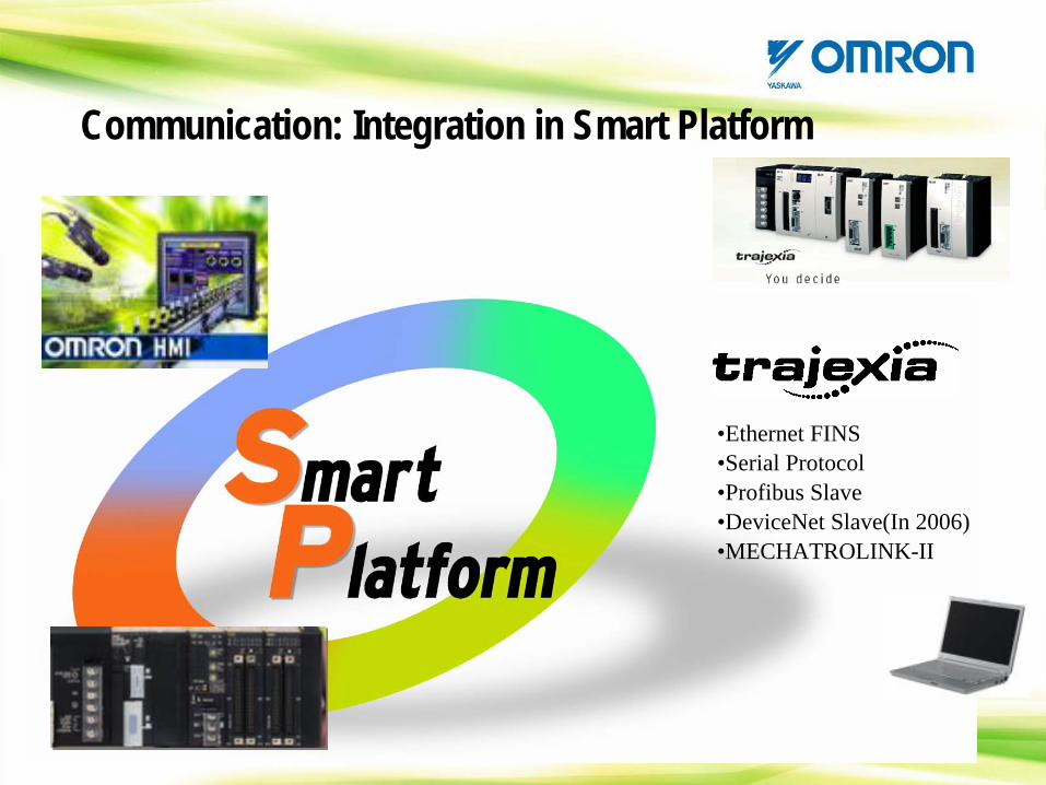
•Ethernet FINS•Serial Protocol•Profibus Slave•DeviceNet Slave(In 2006)•MECHATROLINK-II
Communication: Integration in Smart Platform
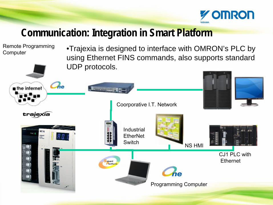
•Trajexia is designed to interface with OMRON’s PLC by using Ethernet FINS commands, also supports standard UDP protocols.
Industrial EtherNet
Switch
Programming Computer
CJ1 PLC withEthernet
Coorporative
I.T. Network
Remote Programming Computer
NS HMI
Communication: Integration in Smart Platform
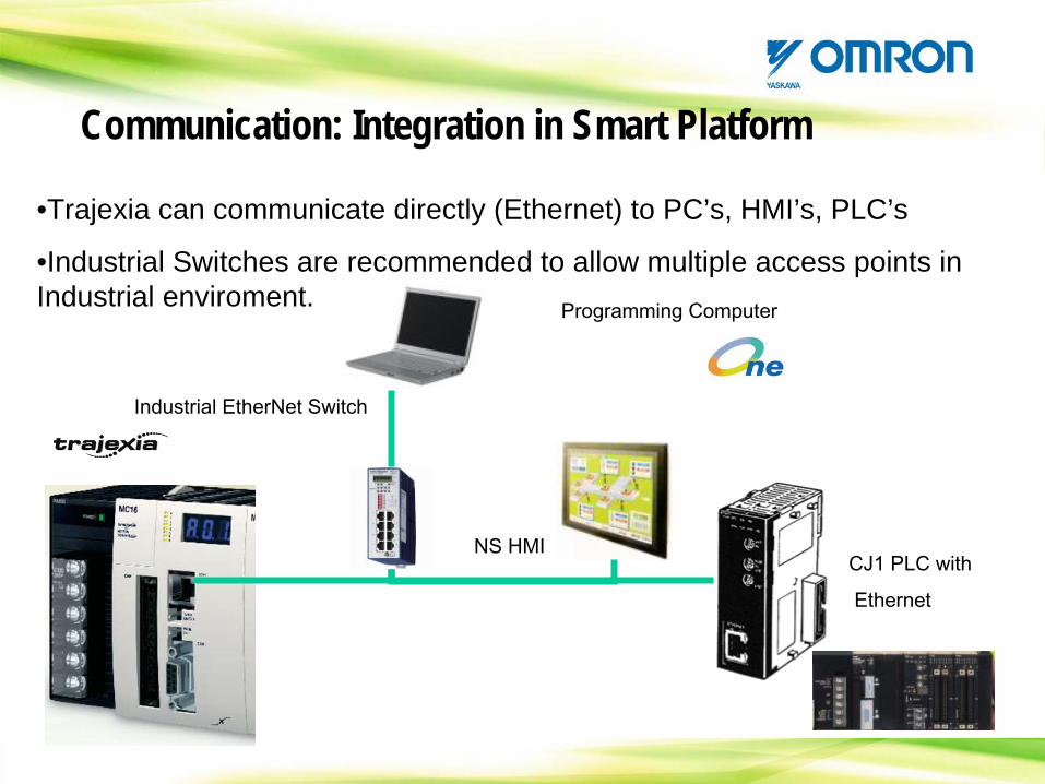
•Trajexia can communicate directly (Ethernet) to PC’s, HMI’s, PLC’s
•Industrial Switches are recommended to allow multiple access points in Industrial enviroment.
Industrial EtherNet
Switch
Programming Computer
CJ1 PLC with
Ethernet
NS HMI
Communication: Integration in Smart Platform
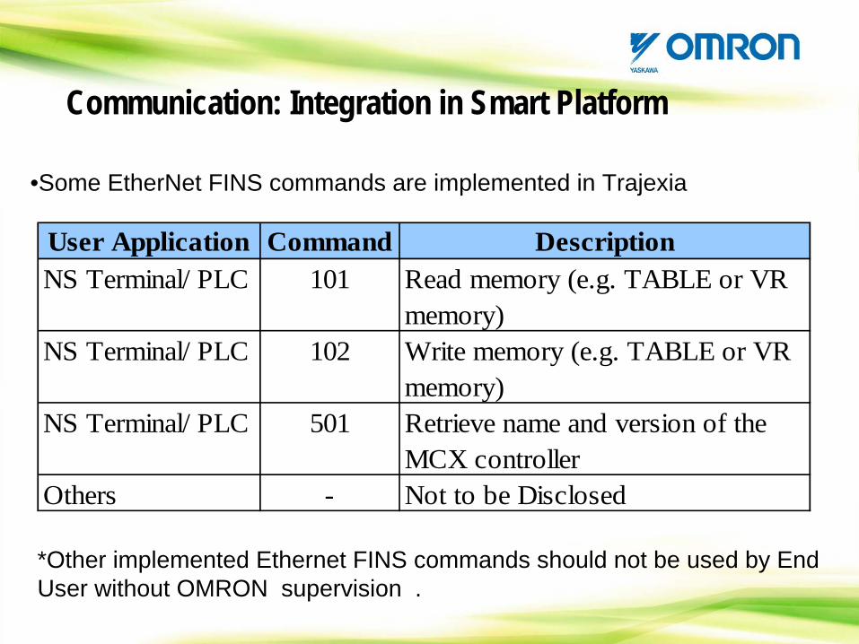
•Some EtherNet FINS commands are implemented in Trajexia
User Application Command DescriptionNS Terminal/ PLC 101 Read memory (e.g. TABLE or VR
memory)NS Terminal/ PLC 102 Write memory (e.g. TABLE or VR
memory)NS Terminal/ PLC 501 Retrieve name and version of the
MCX controllerOthers - Not to be Disclosed
*Other implemented Ethernet FINS commands should not be used by End User without OMRON supervision .
Communication: Integration in Smart Platform
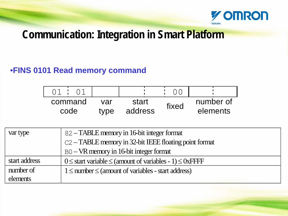
•FINS 0101 Read memory command
01 01 00 command
code var type
start address fixed number of
elements
var type 82 – TABLE memory in 16-bit integer format C2 – TABLE memory in 32-bit IEEE floating point format B0 – VR memory in 16-bit integer format
start address 0 ≤ start variable ≤ (amount of variables - 1) ≤ 0xFFFF number of elements
1 ≤ number ≤ (amount of variables - start address)
Communication: Integration in Smart Platform
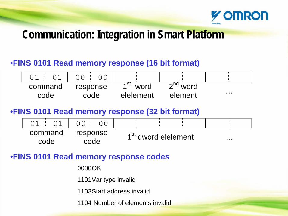
•FINS 0101 Read memory response (16 bit format)
01 01 00 00 command
code response
code 1st word elelement
2nd word element …
•FINS 0101 Read memory response (32 bit format)01 01 00 00 command
code response
code 1st dword elelement …
•FINS 0101 Read memory response codes0000OK
1101Var type invalid
1103Start address invalid
1104 Number of elements invalid
Communication: Integration in Smart Platform
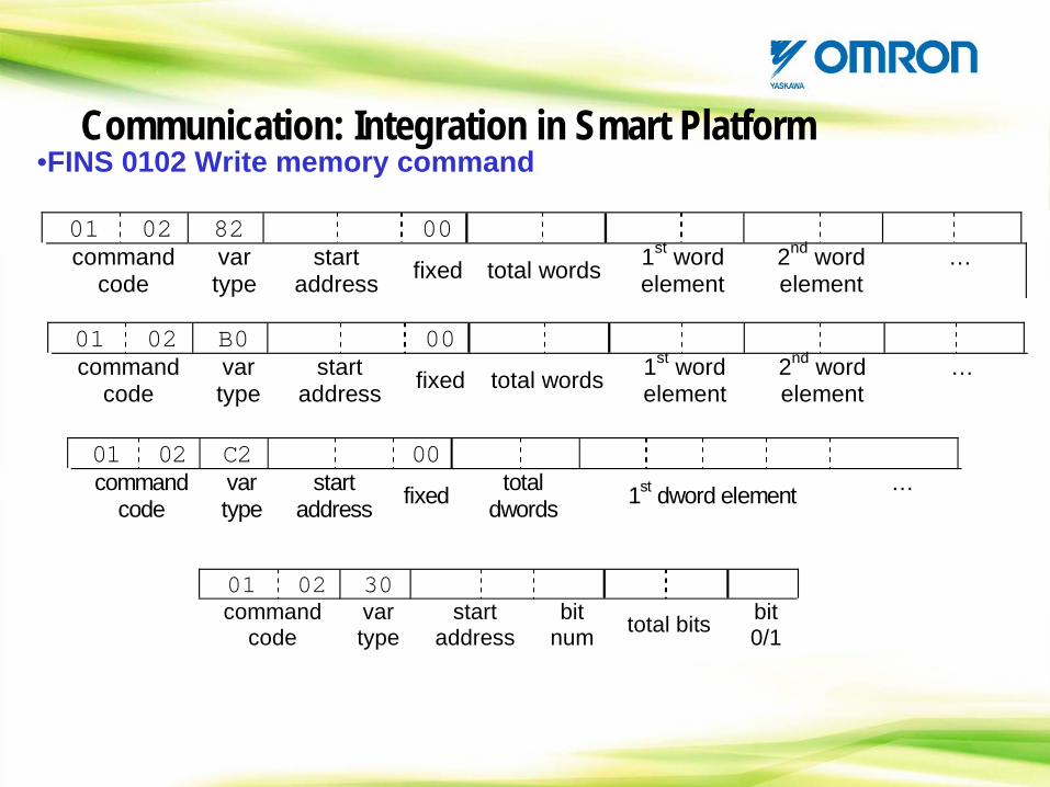
•FINS 0102 Write memory command
01 02 82 00 command
code var type
start address fixed total words 1st word
element 2nd word element
…
01 02 B0 00 command
code var type
start address fixed total words 1st word
element 2nd word element
…
01 02 C2 00 command
code var type
start address fixed total
dwords 1st dword element …
01 02 30 command
code var type
start address
bit num total bits bit
0/1
Communication: Integration in Smart Platform
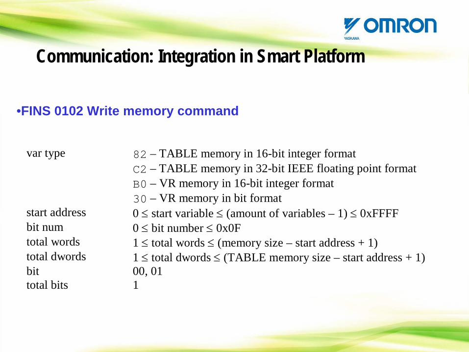
•FINS 0102 Write memory command
var type 82 – TABLE memory in 16-bit integer format C2 – TABLE memory in 32-bit IEEE floating point format B0 – VR memory in 16-bit integer format 30 – VR memory in bit format
start address 0 ≤ start variable ≤ (amount of variables – 1) ≤ 0xFFFF bit num 0 ≤ bit number ≤ 0x0F total words 1 ≤ total words ≤ (memory size – start address + 1) total dwords 1 ≤ total dwords ≤ (TABLE memory size – start address + 1) bit 00, 01 total bits 1
Communication: Integration in Smart Platform
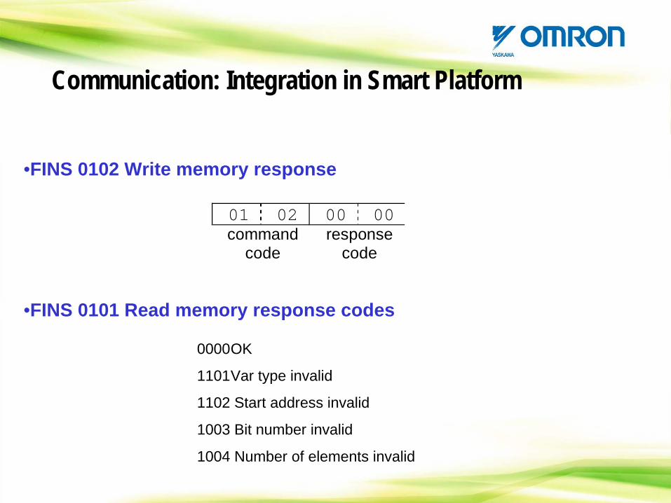
•FINS 0102 Write memory response
01 02 00 00 command
code response
code
•FINS 0101 Read memory response codes
0000OK
1101Var type invalid
1102 Start address invalid
1003 Bit number invalid
1004 Number of elements invalid
Communication: Integration in Smart Platform
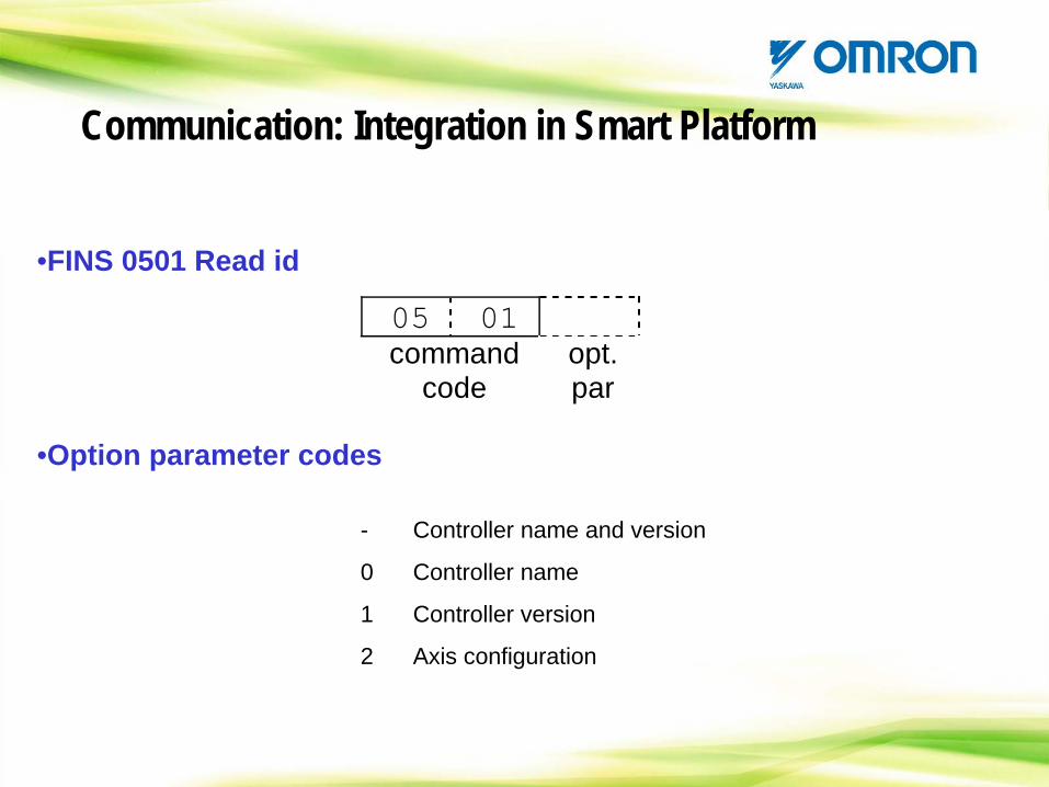
•FINS 0501 Read id
05 01 command
code opt. par
•Option parameter codes
- Controller name and version
0 Controller name
1 Controller version
2 Axis configuration
Communication: Integration in Smart Platform
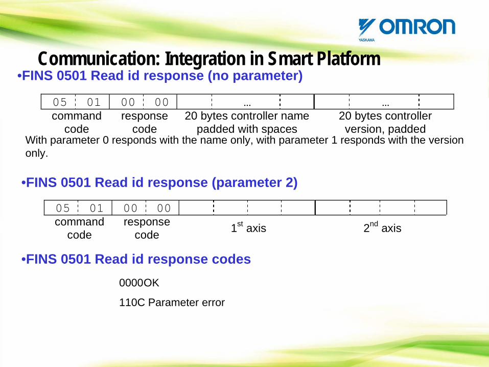
•FINS 0501 Read id response (no parameter)
05 01 00 00 … … command
code response
code 20 bytes controller name
padded with spaces 20 bytes controller version, padded
•FINS 0501 Read id response (parameter 2)
05 01 00 00 command
code response
code 1st axis 2nd axis
With parameter 0 responds with the name only, with parameter 1 responds with the version only.
•FINS 0501 Read id response codes0000OK
110C Parameter error
Communication: Integration in Smart Platform
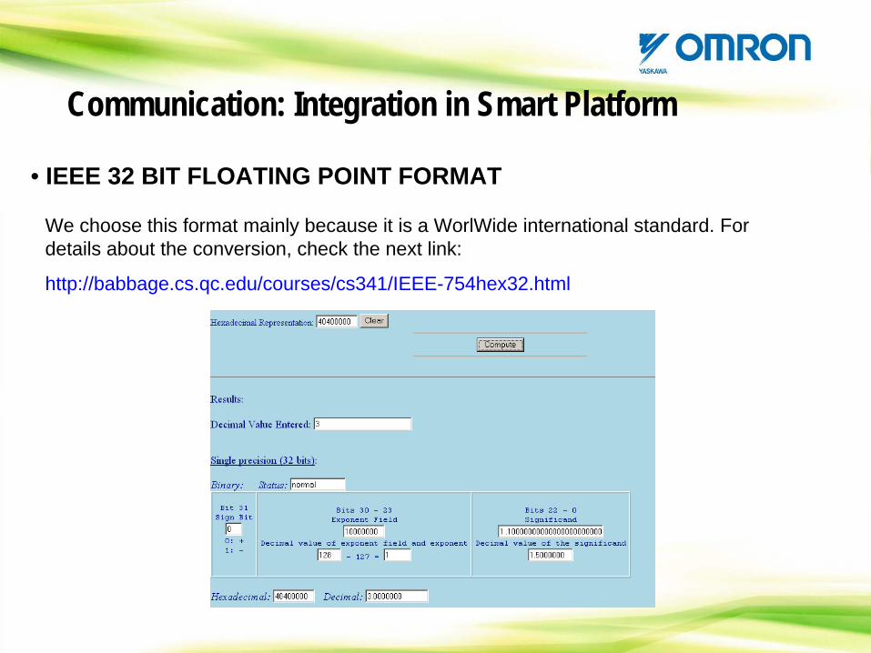
• IEEE 32 BIT FLOATING POINT FORMAT
We choose this format mainly because it is a WorlWide international standard. For details about the conversion, check the next link:
http://babbage.cs.qc.edu/courses/cs341/IEEE-754hex32.html
Communication: Integration in Smart Platform
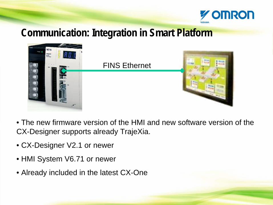
FINS Ethernet
• The new firmware version of the HMI and new software version of the CX-Designer supports already TrajeXia.
• CX-Designer V2.1 or newer
• HMI System V6.71 or newer
• Already included in the latest CX-One
Communication: Integration in Smart Platform
HANDS ON: Let’s Try the FINS via HMI
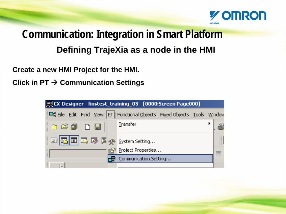
Create a new HMI Project for the HMI.
Click in PT Communication Settings
Defining TrajeXia as a node in the HMICommunication: Integration in Smart Platform
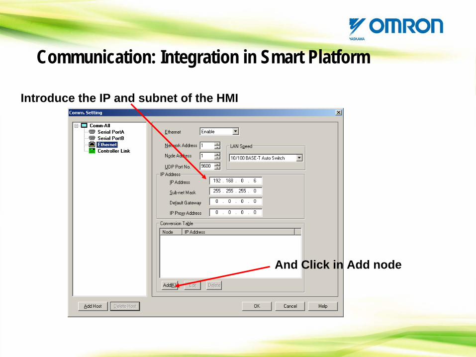
Introduce the IP and subnet of the HMI
And Click in Add node
Communication: Integration in Smart Platform
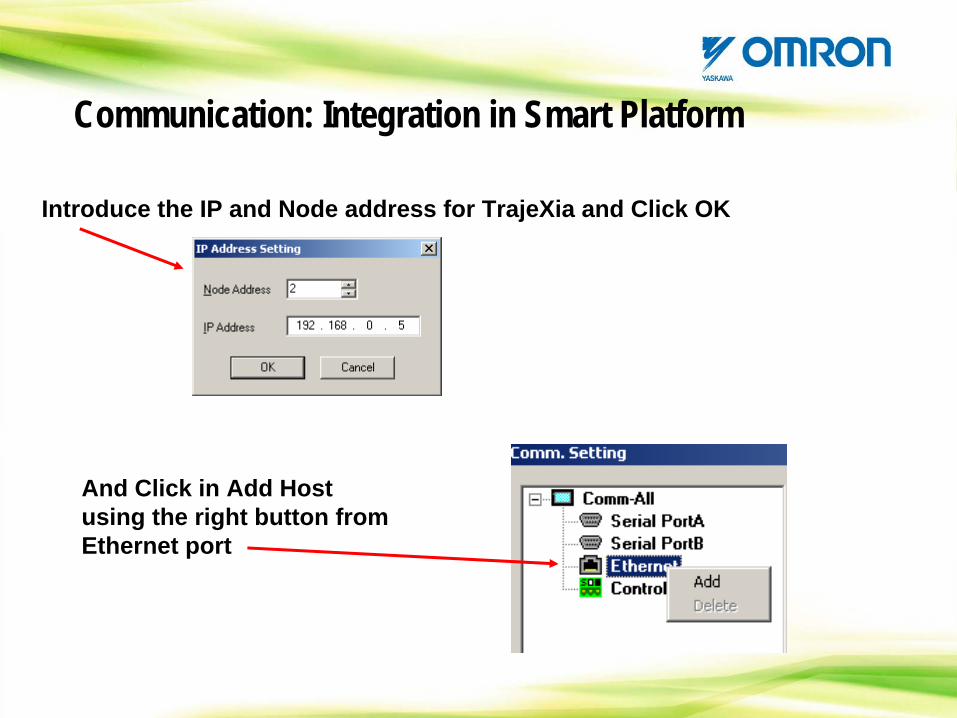
Introduce the IP and Node address for TrajeXia and Click OK
And Click in Add Host using the right button from Ethernet port
Communication: Integration in Smart Platform
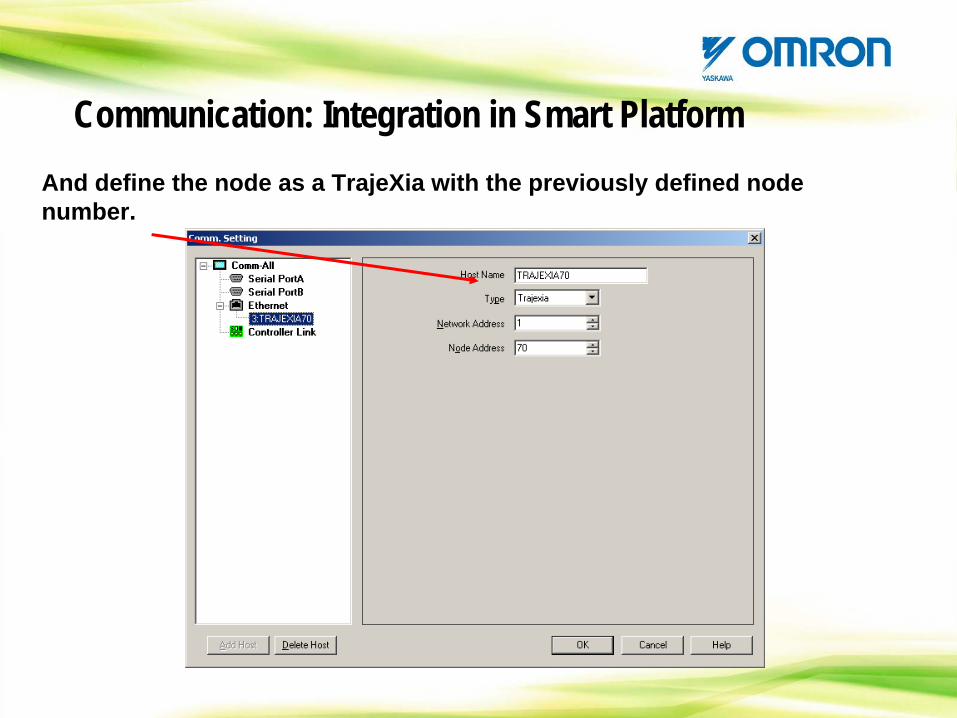
And define the node as a TrajeXia with the previously defined node number.
Communication: Integration in Smart Platform
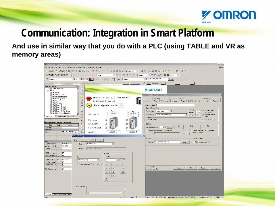
And use in similar way that you do with a PLC (using TABLE and VR as memory areas)
Communication: Integration in Smart Platform

Ethernet FINS & with PLC’s
Communication: Integration in Smart Platform
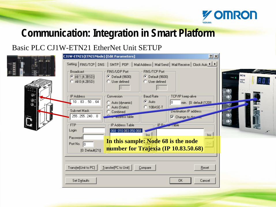
Basic PLC CJ1W-ETN21 EtherNet Unit SETUP
In this sample: Node 68 is the node number for Trajexia (IP 10.83.50.68)
Communication: Integration in Smart Platform
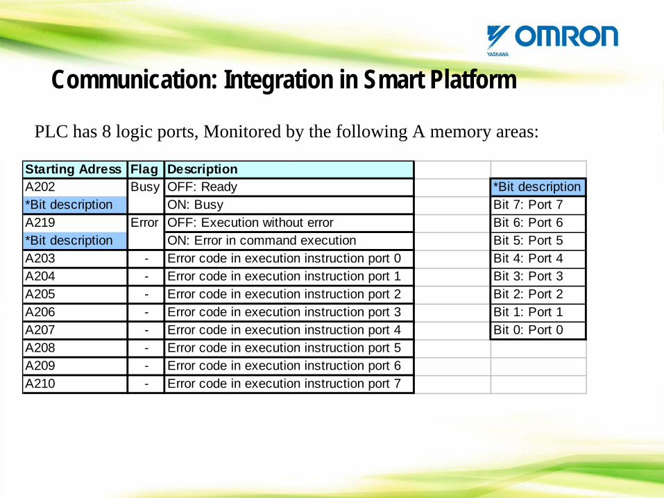
PLC has 8 logic ports, Monitored by the following A memory areas:
Starting Adress Flag DescriptionA202 Busy OFF: Ready *Bit description*Bit description ON: Busy Bit 7: Port 7A219 Error OFF: Execution without error Bit 6: Port 6*Bit description ON: Error in command execution Bit 5: Port 5A203 - Error code in execution instruction port 0 Bit 4: Port 4A204 - Error code in execution instruction port 1 Bit 3: Port 3A205 - Error code in execution instruction port 2 Bit 2: Port 2A206 - Error code in execution instruction port 3 Bit 1: Port 1A207 - Error code in execution instruction port 4 Bit 0: Port 0A208 - Error code in execution instruction port 5A209 - Error code in execution instruction port 6A210 - Error code in execution instruction port 7
Communication: Integration in Smart Platform
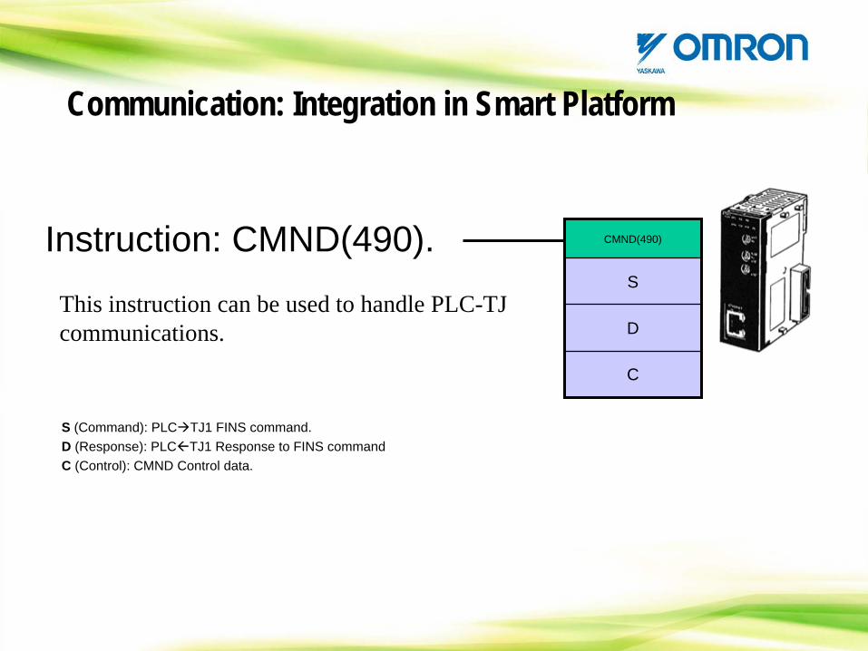
Instruction: CMND(490). CMND(490)
S
D
C
S (Command): PLC TJ1 FINS command.D (Response): PLC TJ1 Response to FINS commandC (Control): CMND Control data.
This instruction can be used to handle PLC-TJ communications.
Communication: Integration in Smart Platform
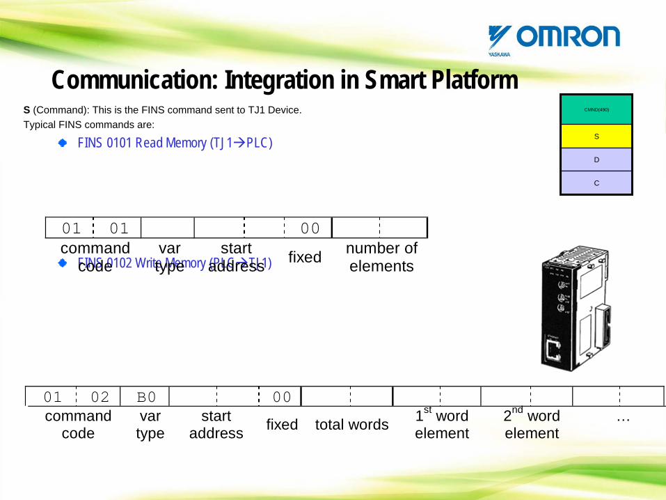
CMND(490)
S
D
C
S (Command): This is the FINS command sent to TJ1 Device.Typical FINS commands are:
FINS 0101 Read Memory (TJ1 PLC)
FINS 0102 Write Memory (PLC TJ1)
01 01 00 command
code var type
start address fixed number of
elements
01 02 B0 00 command
code var type
start address fixed total words 1st word
element 2nd word element
…
Communication: Integration in Smart Platform
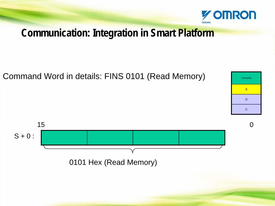
Command Word in details: FINS 0101 (Read Memory)
S + 0 :
15 0
0101 Hex (Read Memory)
CMND(490)
S
D
C
Communication: Integration in Smart Platform
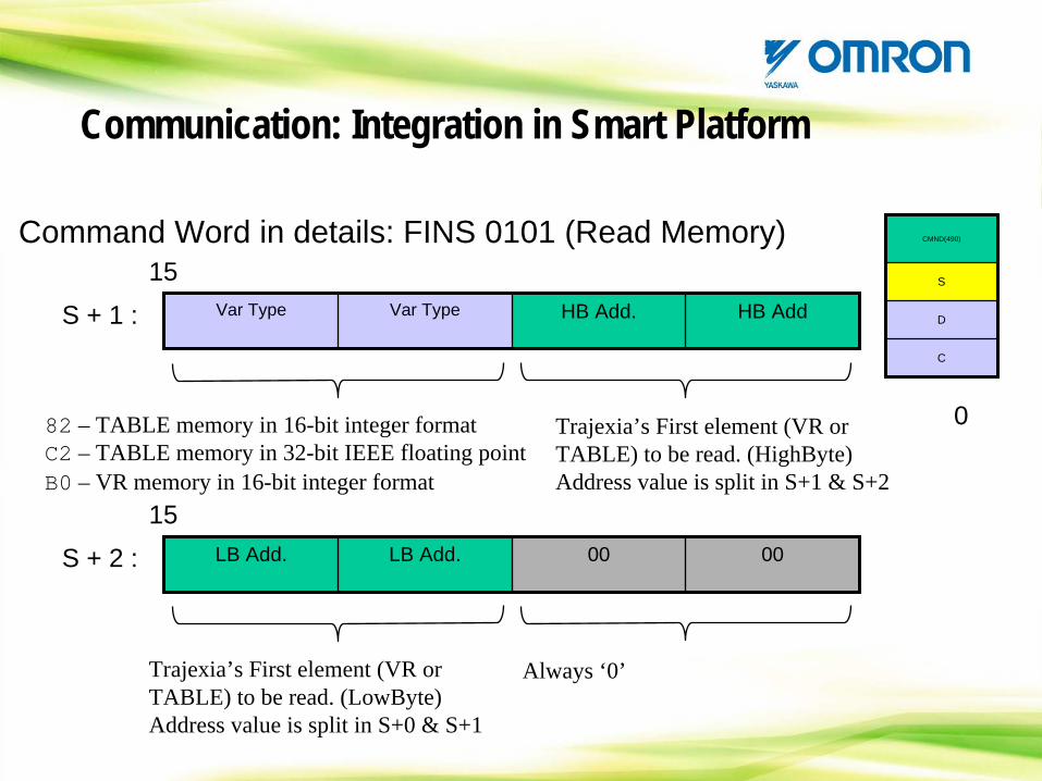
Var Type Var Type HB Add. HB AddS + 1 :
15
0
LB Add. LB Add. 00 00S + 2 :
15
82 – TABLE memory in 16-bit integer formatC2 – TABLE memory in 32-bit IEEE floating point B0 – VR memory in 16-bit integer format
Trajexia’s First element (VR or TABLE) to be read. (HighByte)Address value is split in S+1 & S+2
Trajexia’s First element (VR or TABLE) to be read. (LowByte)Address value is split in S+0 & S+1
Always ‘0’
CMND(490)
S
D
C
Command Word in details: FINS 0101 (Read Memory)
Communication: Integration in Smart Platform
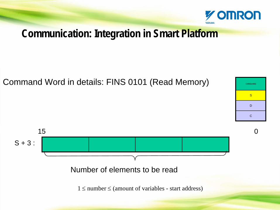
S + 3 :
15 0
Number of elements to be read
1 ≤
number ≤
(amount of variables - start address)
CMND(490)
S
D
C
Command Word in details: FINS 0101 (Read Memory)
Communication: Integration in Smart Platform
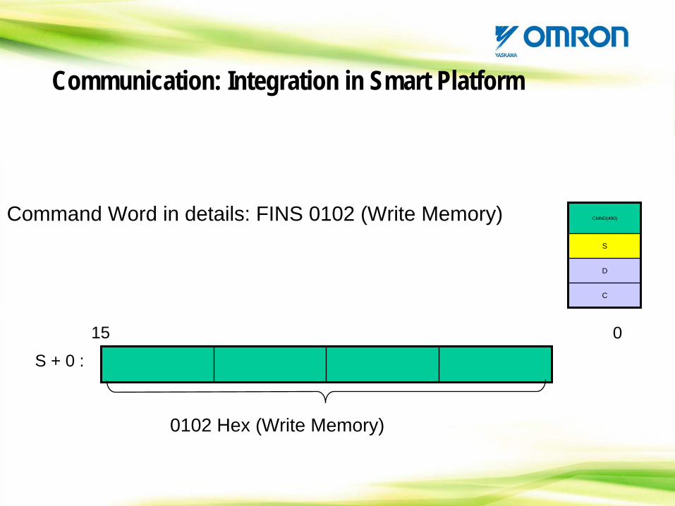
S + 0 :
15 0
0102 Hex (Write Memory)
CMND(490)
S
D
C
Command Word in details: FINS 0102 (Write Memory)
Communication: Integration in Smart Platform
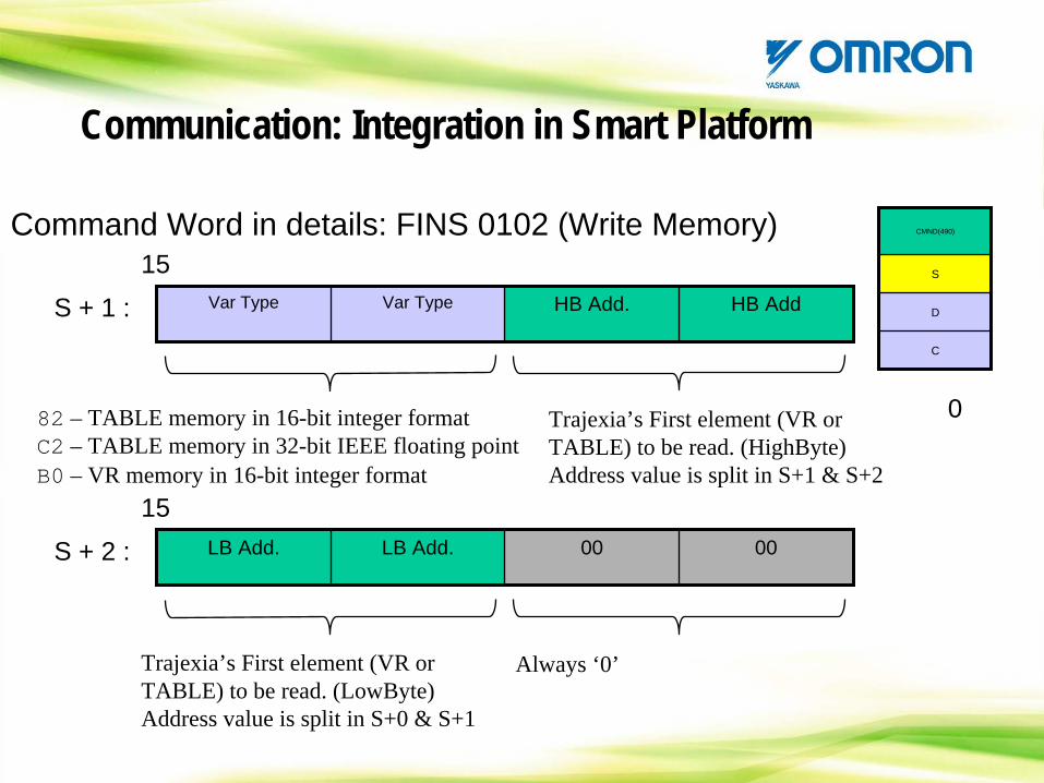
Var Type Var Type HB Add. HB AddS + 1 :
15
0
LB Add. LB Add. 00 00S + 2 :
15
82 – TABLE memory in 16-bit integer formatC2 – TABLE memory in 32-bit IEEE floating point B0 – VR memory in 16-bit integer format
Trajexia’s First element (VR or TABLE) to be read. (HighByte)Address value is split in S+1 & S+2
Trajexia’s First element (VR or TABLE) to be read. (LowByte)Address value is split in S+0 & S+1
Always ‘0’
CMND(490)
S
D
C
Command Word in details: FINS 0102 (Write Memory)
Communication: Integration in Smart Platform
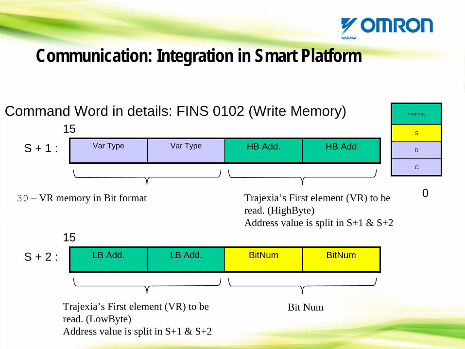
Var Type Var Type HB Add. HB AddS + 1 :
15
0
LB Add. LB Add. BitNum BitNumS + 2 :
15
30 – VR memory in Bit format Trajexia’s First element (VR) to be read. (HighByte)Address value is split in S+1 & S+2
Trajexia’s First element (VR) to be read. (LowByte)Address value is split in S+1 & S+2
Bit Num
CMND(490)
S
D
C
Command Word in details: FINS 0102 (Write Memory)
Communication: Integration in Smart Platform
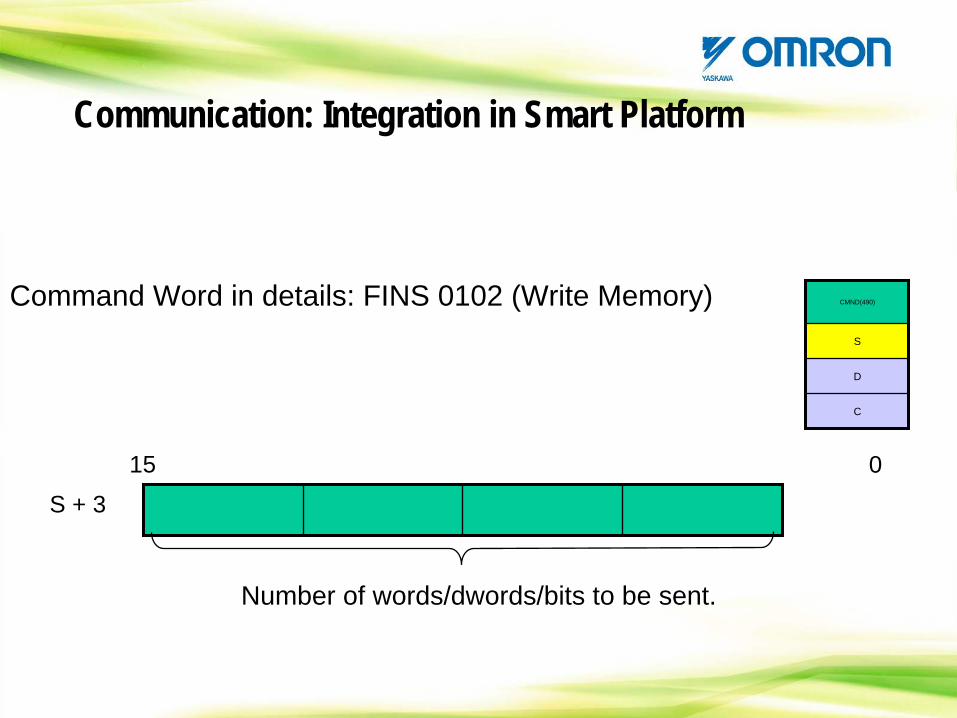
S + 3
15 0
Number of words/dwords/bits to be sent.
CMND(490)
S
D
C
Command Word in details: FINS 0102 (Write Memory)
Communication: Integration in Smart Platform
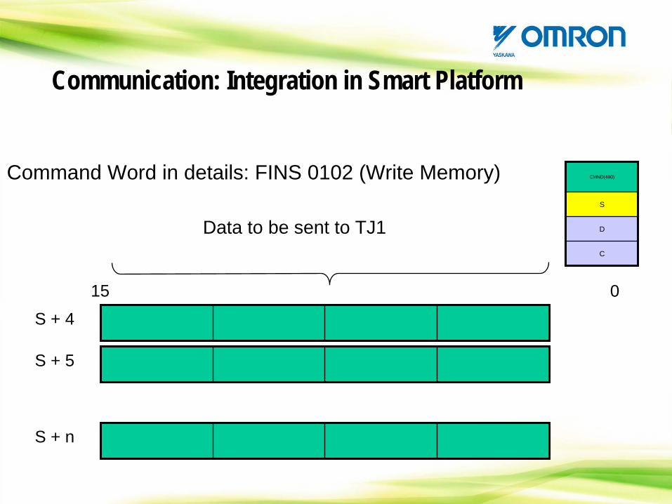
S + 4
15 0
Data to be sent to TJ1
CMND(490)
S
D
C
Command Word in details: FINS 0102 (Write Memory)
S + 5
S + n
Communication: Integration in Smart Platform
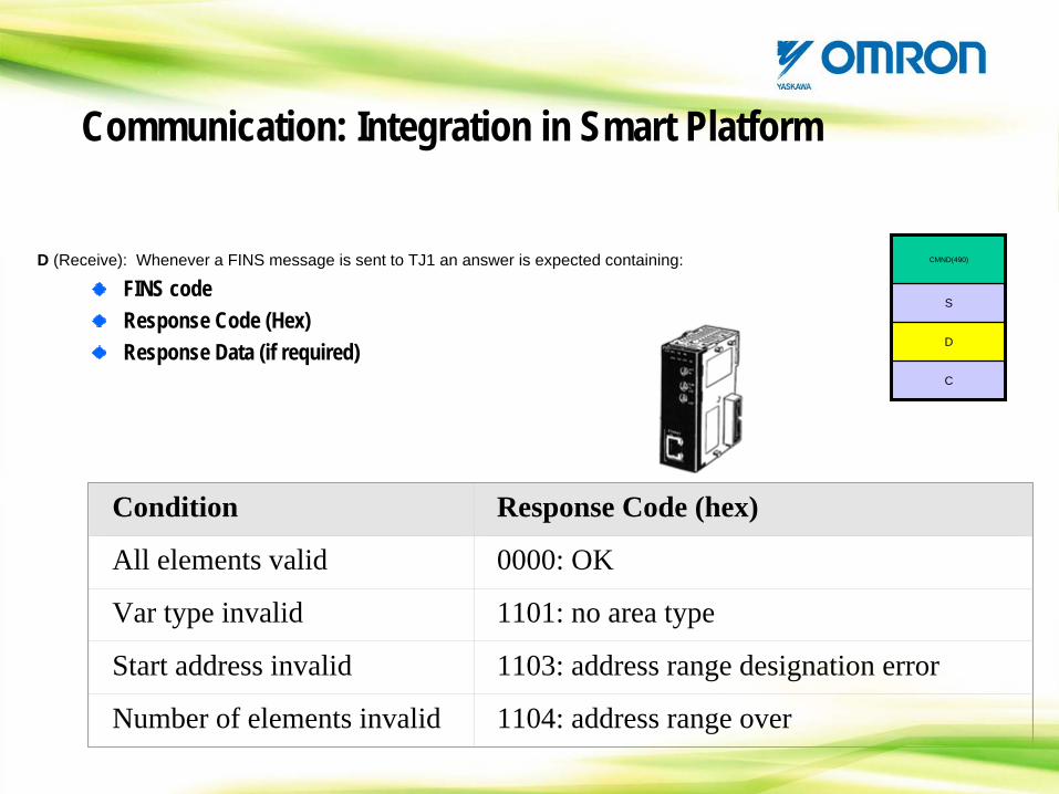
CMND(490)
S
D
C
D (Receive): Whenever a FINS message is sent to TJ1 an answer is expected containing:
FINS codeResponse Code (Hex)Response Data (if required)
Condition Response Code (hex)
All elements valid 0000: OK
Var type invalid 1101: no area type
Start address invalid 1103: address range designation error
Number of elements invalid 1104: address range over
Communication: Integration in Smart Platform
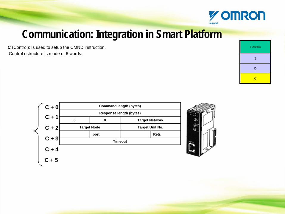
C (Control): Is used to setup the CMND instruction. Control estructure is made of 6 words:
Command length (bytes)
Response length (bytes)
0 0 Target Network
Target Node Target Unit No.
port Retr.
Timeout
C + 0
C + 1
C + 2
C + 3
C + 4
C + 5
CMND(490)
S
D
C
Communication: Integration in Smart Platform
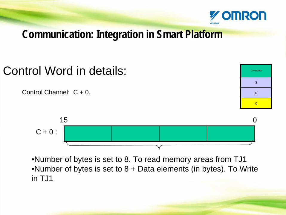
Control Word in details:Control Channel: C + 0.
C + 0 :
15 0
•Number of bytes is set to 8. To read memory areas from TJ1•Number of bytes is set to 8 + Data elements (in bytes). To Write in TJ1
CMND(490)
S
D
C
Communication: Integration in Smart Platform

Control Word in details:
C + 1 :
15 0
Response size (Bytes).Allowed range:0001 to 07C6 (hex.): 1 to 1990 bytes.
Control Channel: C + 1.
CMND(490)
S
D
C
Communication: Integration in Smart Platform
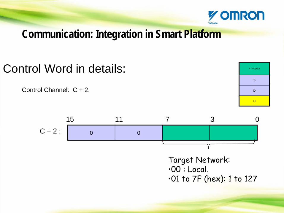
Control Word in details:Control Channel: C + 2.
0 0C + 2 :
15 0
Target Network:•00 : Local.•01
to
7F (hex): 1
to
127
11 7 3
CMND(490)
S
D
C
Communication: Integration in Smart Platform
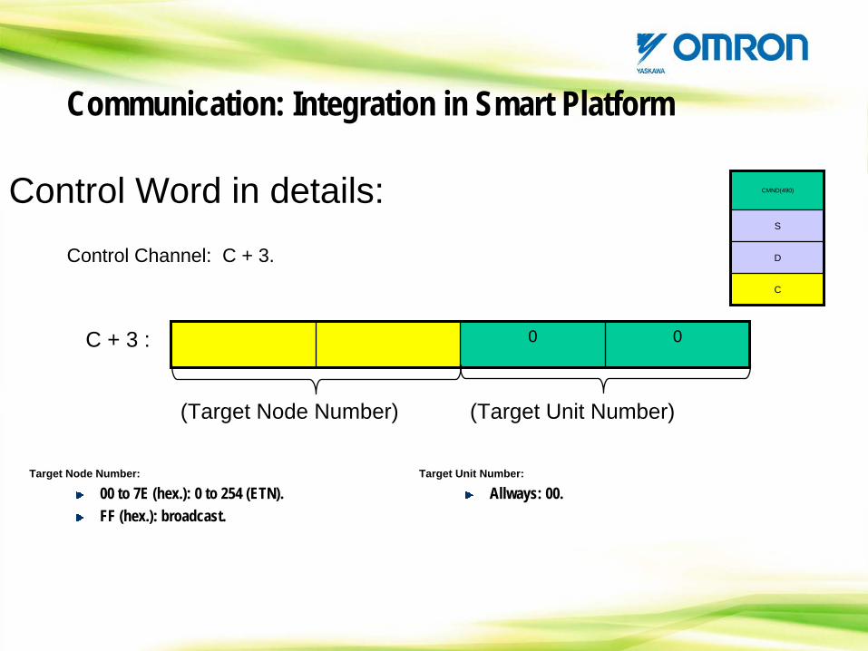
Control Word in details:Control Channel: C + 3.
0 0C + 3 :
(Target Unit Number)(Target Node Number)
Target Node Number:
00 to 7E (hex.): 0 to 254 (ETN).FF (hex.): broadcast.
Target Unit Number:
Allways: 00.
CMND(490)
S
D
C
Communication: Integration in Smart Platform
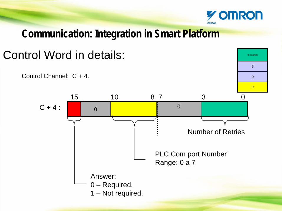
Control Word in details:Control Channel: C + 4.
0 0C + 4 :15 010 7 3
Number of Retries
Answer:0 – Required.1 – Not required.
8
PLC Com port NumberRange: 0 a 7
CMND(490)
S
D
C
Communication: Integration in Smart Platform
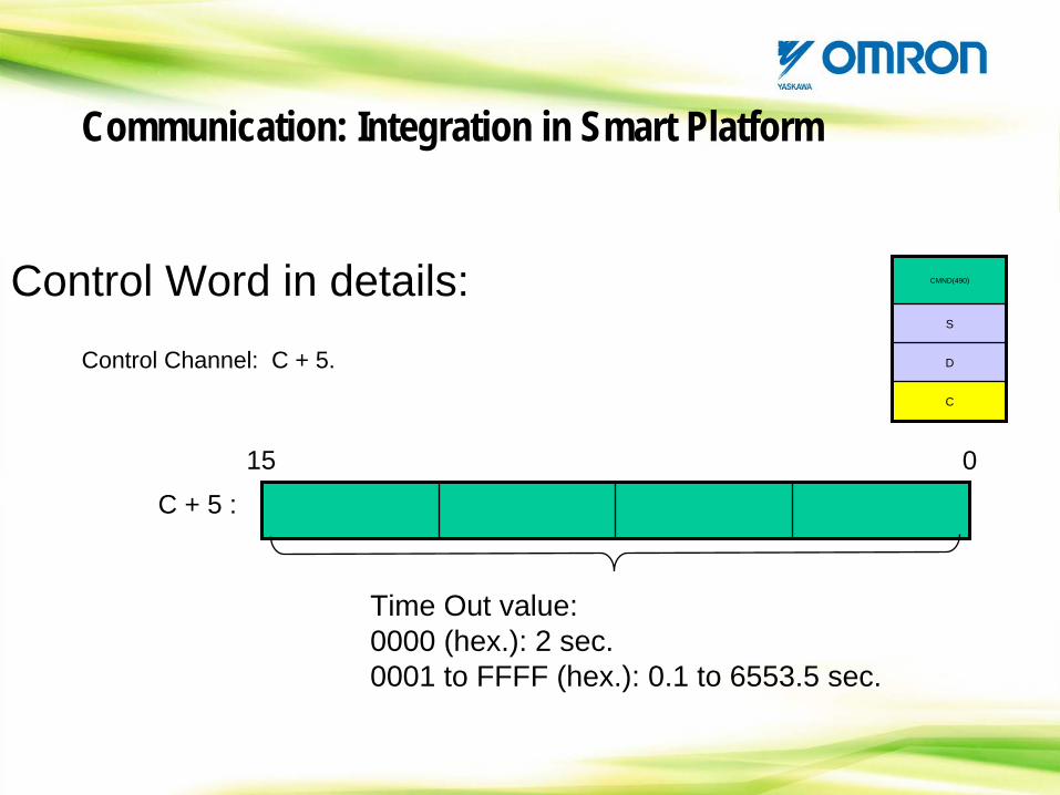
Control Word in details:Control Channel: C + 5.
C + 5 :
15 0
Time Out value:0000 (hex.): 2 sec.0001 to FFFF (hex.): 0.1 to 6553.5 sec.
CMND(490)
S
D
C
Communication: Integration in Smart Platform
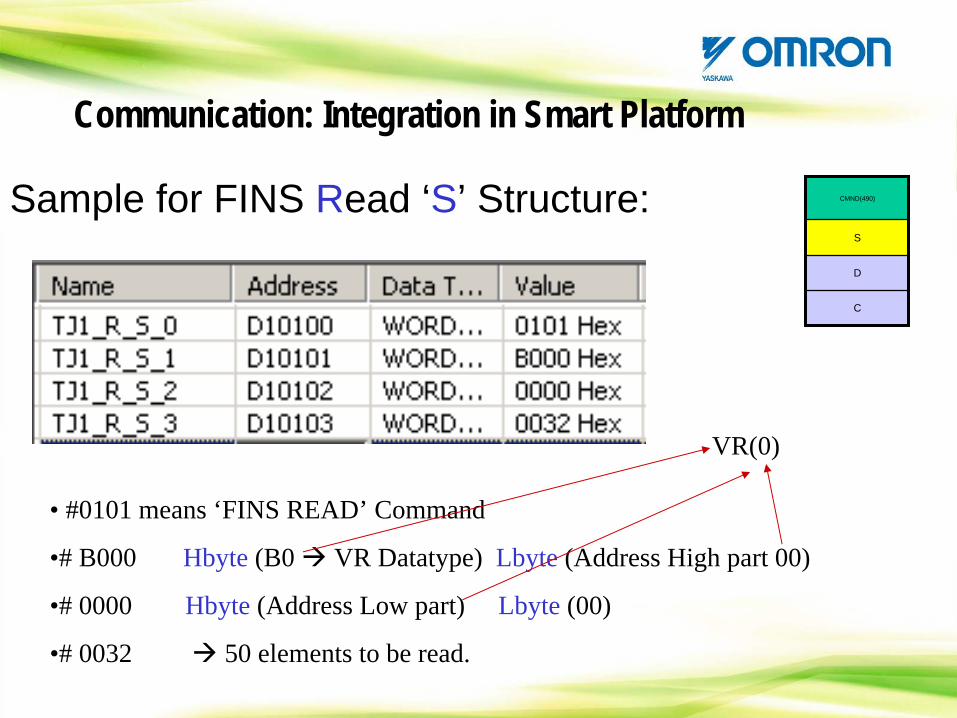
Sample for FINS Read ‘S’ Structure: CMND(490)
S
D
C
• #0101 means ‘FINS READ’ Command
•# B000 Hbyte (B0 VR Datatype) Lbyte (Address High part 00)
•# 0000 Hbyte (Address Low part) Lbyte (00)
•# 0032 50 elements to be read.
VR(0)
Communication: Integration in Smart Platform
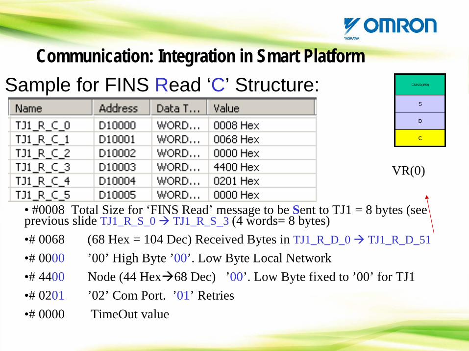
Sample for FINS Read ‘C’ Structure: CMND(490)
S
D
C
• #0008 Total Size for ‘FINS Read’ message to be Sent to TJ1 = 8 bytes (see previous slide TJ1_R_S_0 TJ1_R_S_3 (4 words= 8 bytes)•# 0068 (68 Hex = 104 Dec) Received Bytes in TJ1_R_D_0 TJ1_R_D_51•# 0000 ’00’ High Byte ’00’. Low Byte Local Network •# 4400 Node (44 Hex 68 Dec) ’00’. Low Byte fixed to ’00’ for TJ1•# 0201 ’02’ Com Port. ’01’ Retries•# 0000 TimeOut value
VR(0)
Communication: Integration in Smart Platform
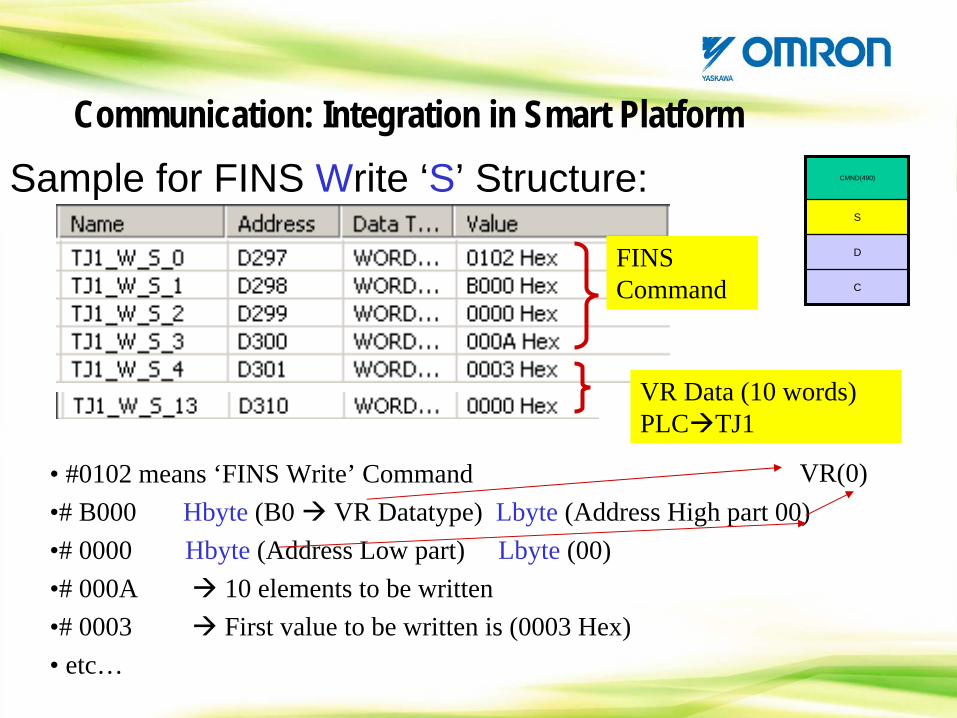
Sample for FINS Write ‘S’ Structure: CMND(490)
S
D
C
• #0102 means ‘FINS Write’ Command•# B000 Hbyte (B0 VR Datatype) Lbyte (Address High part 00)•# 0000 Hbyte (Address Low part) Lbyte (00) •# 000A 10 elements to be written •# 0003 First value to be written is (0003 Hex)• etc…
VR(0)
FINS Command
VR Data (10 words) PLC TJ1
Communication: Integration in Smart Platform
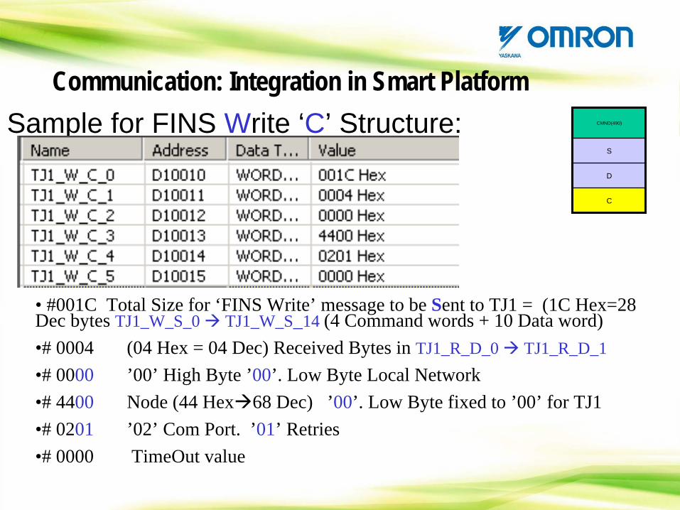
Sample for FINS Write ‘C’ Structure: CMND(490)
S
D
C
• #001C Total Size for ‘FINS Write’ message to be Sent to TJ1 = (1C Hex=28 Dec bytes TJ1_W_S_0 TJ1_W_S_14 (4 Command words + 10 Data word)•# 0004 (04 Hex = 04 Dec) Received Bytes in TJ1_R_D_0 TJ1_R_D_1•# 0000 ’00’ High Byte ’00’. Low Byte Local Network •# 4400 Node (44 Hex 68 Dec) ’00’. Low Byte fixed to ’00’ for TJ1•# 0201 ’02’ Com Port. ’01’ Retries•# 0000 TimeOut value
Communication: Integration in Smart Platform
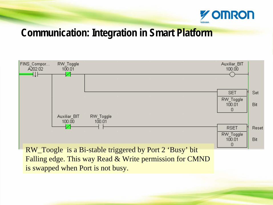
RW_Toogle is a Bi-stable triggered by Port 2 ‘Busy’ bit Falling edge. This way Read & Write permission for CMND is swapped when Port is not busy.
Communication: Integration in Smart Platform
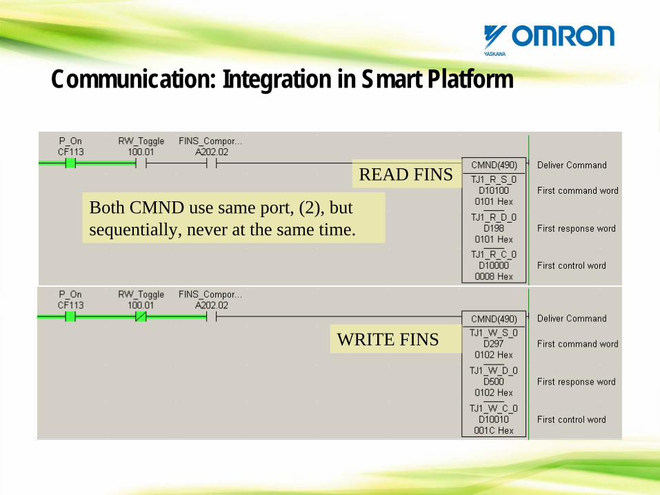
Both CMND use same port, (2), but sequentially, never at the same time.
READ FINS
WRITE FINS
Communication: Integration in Smart Platform
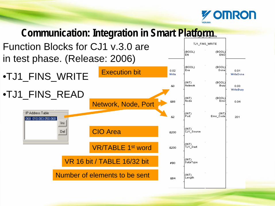
Function Blocks for CJ1 v.3.0 are in test phase. (Release: 2006)
•TJ1_FINS_WRITE
•TJ1_FINS_READ
CIO Area
VR/TABLE 1st word
VR 16 bit / TABLE 16/32 bit
Number of elements to be sent
Execution bit
Network, Node, Port
Communication: Integration in Smart Platform
HANDS ON
Let’s Try FINS via PLC
Communication: Integration in Smart Platform
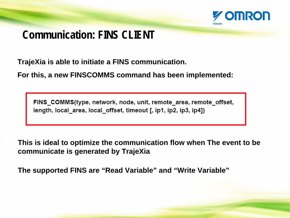
Communication: FINS CLIENT
TrajeXia is able to initiate a FINS communication.
For this, a new FINSCOMMS command has been implemented:
This is ideal to optimize the communication flow when The event to be communicate is generated by TrajeXia
The supported FINS are “Read Variable” and “Write Variable”
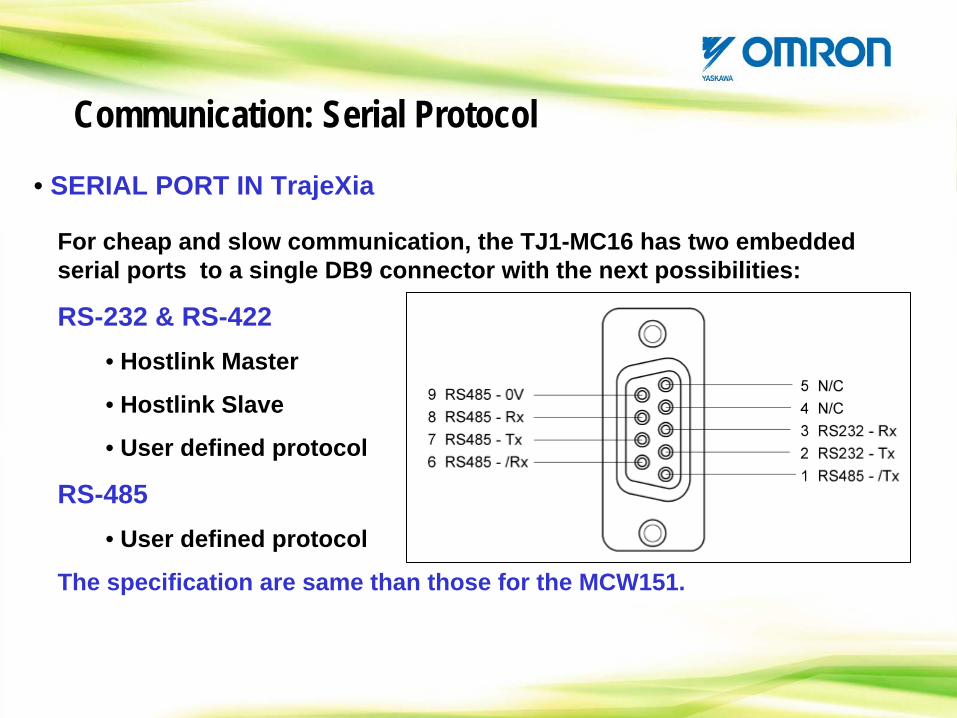
• SERIAL PORT IN TrajeXia
For cheap and slow communication, the TJ1-MC16 has two embedded serial ports to a single DB9 connector with the next possibilities:
RS-232 & RS-422• Hostlink Master
• Hostlink Slave
• User defined protocol
RS-485• User defined protocol
The specification are same than those for the MCW151.
Communication: Serial Protocol
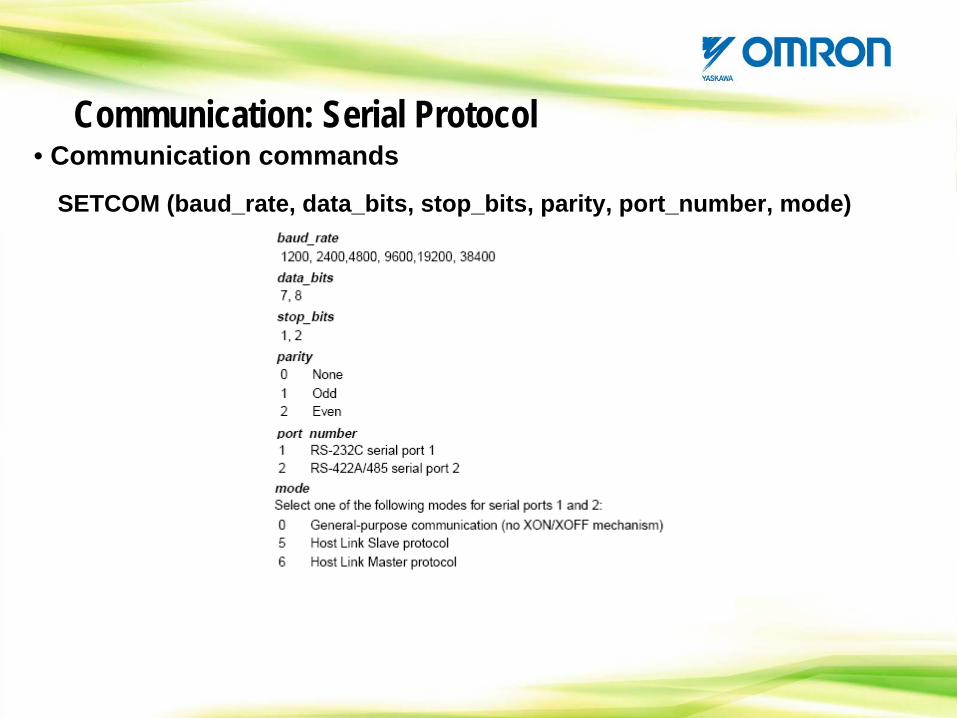
• Communication commands
SETCOM (baud_rate, data_bits, stop_bits, parity, port_number, mode)
Communication: Serial Protocol
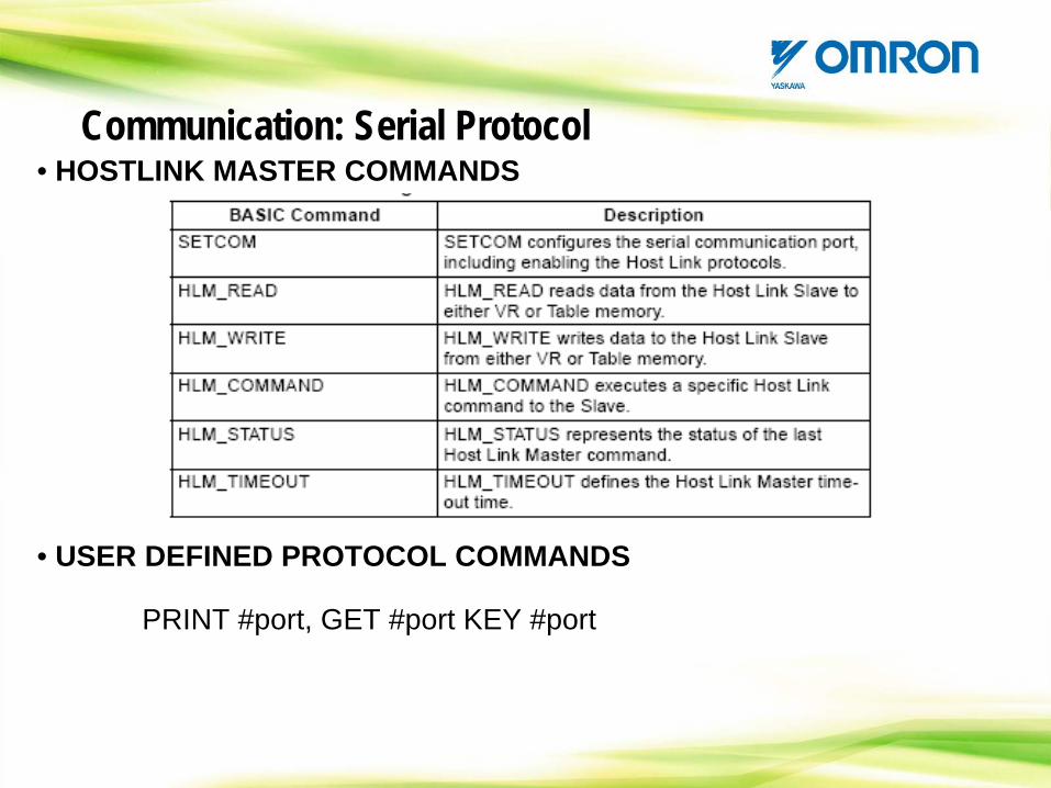
• HOSTLINK MASTER COMMANDS
• USER DEFINED PROTOCOL COMMANDS
PRINT #port, GET #port KEY #port
Communication: Serial Protocol
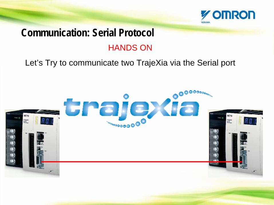
HANDS ON
Let’s Try to communicate two TrajeXia via the Serial port
Communication: Serial Protocol
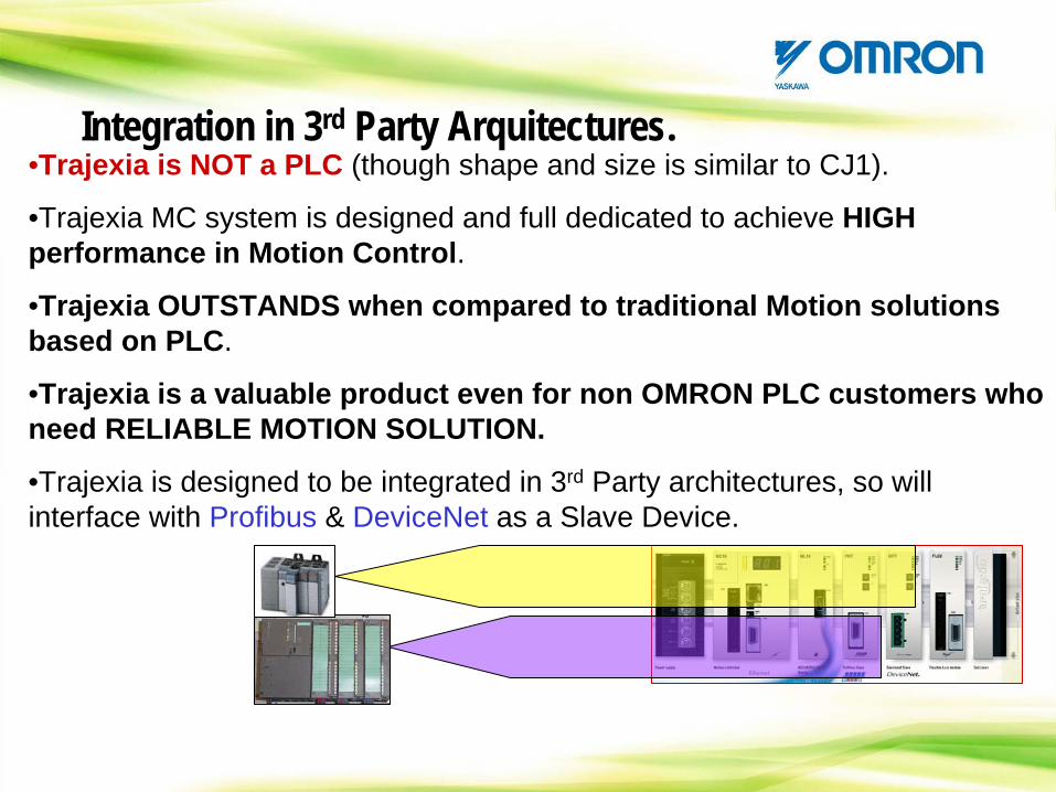
Integration in 3rd Party Arquitectures.•Trajexia is NOT a PLC (though shape and size is similar to CJ1).
•Trajexia MC system is designed and full dedicated to achieve HIGH performance in Motion Control.
•Trajexia OUTSTANDS when compared to traditional Motion solutions based on PLC.
•Trajexia is a valuable product even for non OMRON PLC customers who need RELIABLE MOTION SOLUTION.
•Trajexia is designed to be integrated in 3rd Party architectures, so will interface with Profibus & DeviceNet as a Slave Device.
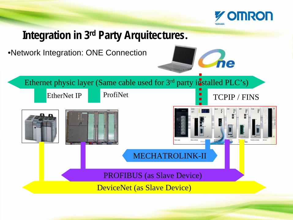
Integration in 3rd Party Arquitectures.•Network Integration: ONE Connection
Ethernet physic layer (Same cable used for 3rd party installed PLC’s)EtherNet IP ProfiNet TCPIP / FINS
DeviceNet (as Slave Device)PROFIBUS (as Slave Device)
MECHATROLINK-II
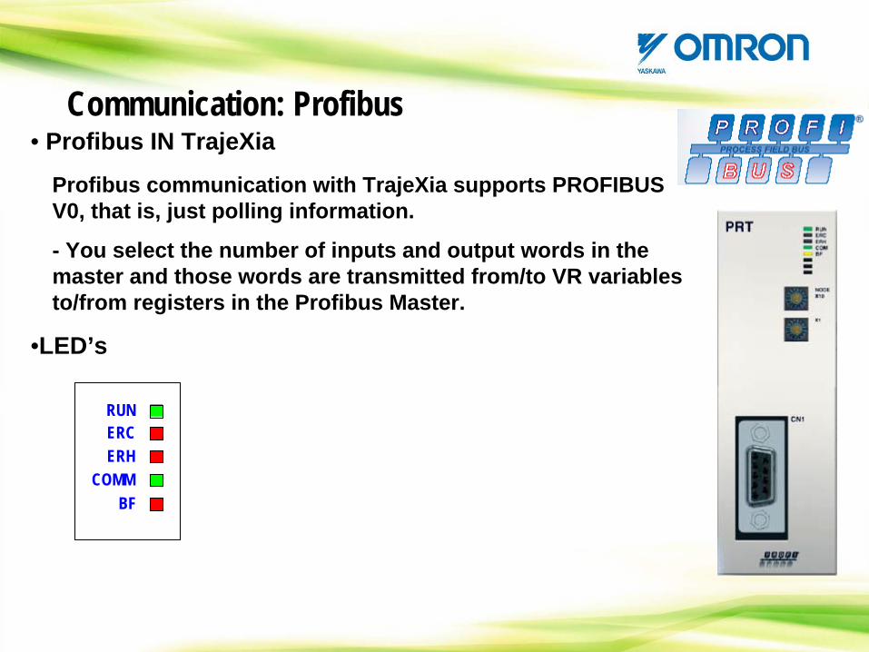
• Profibus IN TrajeXia
Profibus communication with TrajeXia supports PROFIBUS V0, that is, just polling information.
- You select the number of inputs and output words in the master and those words are transmitted from/to VR variables to/from registers in the Profibus Master.
ERCERH
COMMBF
RUN
•LED’s
Communication: Profibus
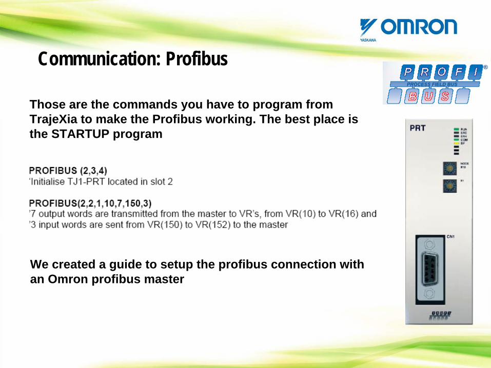
Those are the commands you have to program from TrajeXia to make the Profibus working. The best place is the STARTUP program
Communication: Profibus
We created a guide to setup the profibus connection with an Omron profibus master
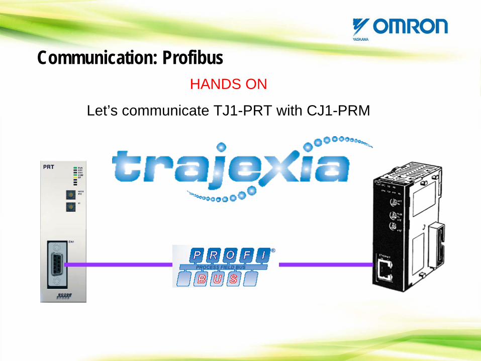
HANDS ON
Let’s communicate TJ1-PRT with CJ1-PRM
Communication: Profibus
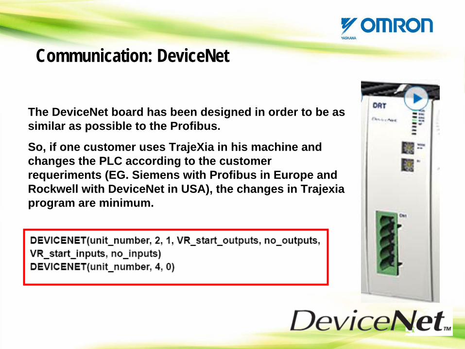
The DeviceNet board has been designed in order to be as similar as possible to the Profibus.
So, if one customer uses TrajeXia in his machine and changes the PLC according to the customer requeriments (EG. Siemens with Profibus in Europe and Rockwell with DeviceNet in USA), the changes in Trajexia program are minimum.
Communication: DeviceNet
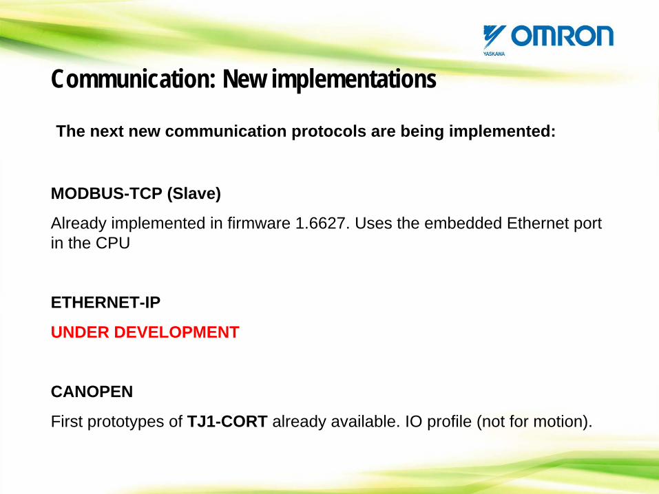
The next new communication protocols are being implemented:
Communication: New implementations
MODBUS-TCP (Slave)
Already implemented in firmware 1.6627. Uses the embedded Ethernet port in the CPU
ETHERNET-IP
UNDER DEVELOPMENT
CANOPEN
First prototypes of TJ1-CORT already available. IO profile (not for motion).
CONTENTS
TrajeXia OverviewHardware and general specification TrajeXia ToolsTrajexia ArchitectureProgramming TrajeXiaHow I do… with TrajeXia?CommunicationTrajeXia success histories
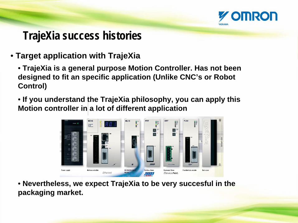
• Target application with TrajeXia• TrajeXia is a general purpose Motion Controller. Has not been designed to fit an specific application (Unlike CNC’s or Robot Control)
• If you understand the TrajeXia philosophy, you can apply this Motion controller in a lot of different application
• Nevertheless, we expect TrajeXia to be very succesful in the packaging market.
TrajeXia success histories
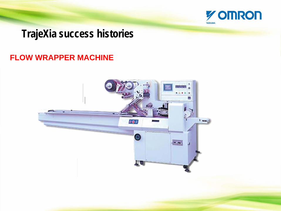
FLOW WRAPPER MACHINE
TrajeXia success histories

• Some Ideas about using TrajeXia in Packaging industry:
• HORIZONTAL CARTONER MACHINE
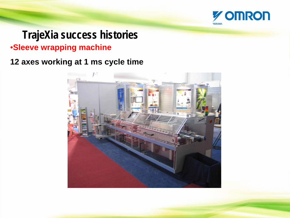
•Sleeve wrapping machine
12 axes working at 1 ms cycle time
TrajeXia success histories
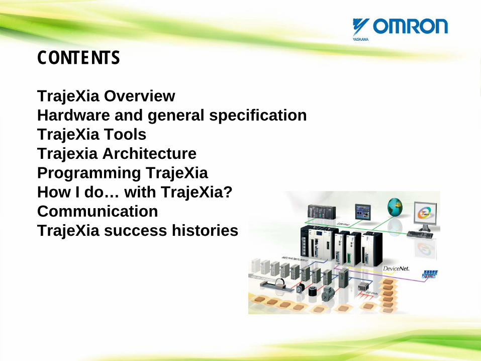
CONTENTS
TrajeXia OverviewHardware and general specification TrajeXia ToolsTrajexia ArchitectureProgramming TrajeXiaHow I do… with TrajeXia?CommunicationTrajeXia success histories

CONTENTS
TrajeXia OverviewHardware and general specification TrajeXia ToolsTrajexia ArchitectureProgramming TrajeXiaHow I do… with TrajeXia?CommunicationTrajeXia success histories